iPhone 11 Lower Speaker Replacement
This document provides instructions for substituting the main audio output transducer located on the lower portion of the iPhone 11 chassis; a separate instructional resource is required for earpiece speaker replacement.The component in question, designated as the 'loudspeaker', is susceptible to failure and may necessitate replacement to rectify audio anomalies.Common symptoms indicating the need for speaker replacement include complete audio absence, diminished sound levels, and the presence of audio distortion.Addressing these audio problems through speaker substitution can restore proper functionality to the device's sound reproduction capabilities.Adherence to these steps is essential for a successful repair and should be performed with the appropriate tools and precautions.
Step 1 | Remove the pentalobe screws
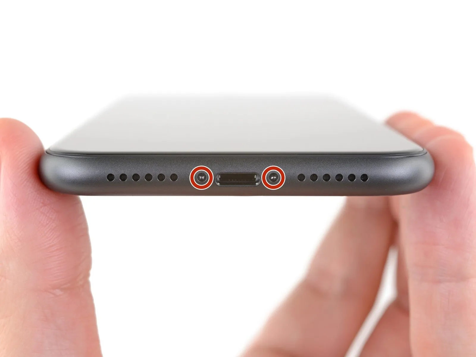
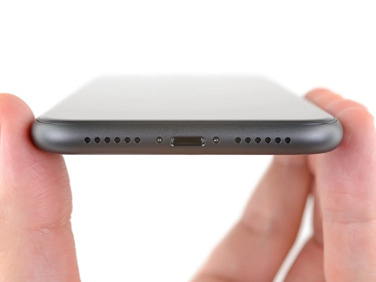
- To ensure safety prior to commencing the repair, allow the iPhone's battery to deplete to a state of charge below 25%.Because of the potential for hazardous events, a fully charged lithium-ion battery presents a fire and/or explosion risk if it sustains accidental physical damage.To prevent electrical shock and facilitate the repair process, completely de-energize the iPhone by powering it down.
- The two screws securing the bottom edge, each measuring 6.7 mm in length and utilizing a pentalobe P2 head, must be removed to proceed.
- The integrity of the iPhone's water resistance is dependent on the display seal; therefore, opening the display will irreversibly damage it.
- To maintain the iPhone's water resistance, either obtain replacement seals beforehand and install them during reassembly, or exercise extreme caution to prevent liquid ingress if the original seals are reused.
Step 2 | Mark your opening picks


- Excessive insertion of a prying tool poses a risk of device damage; implement the following procedure to identify a safe insertion depth and avoid harm.
- Using a precise measuring tool, determine a distance of3 mmfrom the tool's distal end, then clearly indicate this point on the prying tool with a permanent marking instrument.
- For enhanced precision, consider applying distinct markings to the tool's other corners, each representing a different measurement.
- As an alternative method, affix a coin to the prying tool's shaft, positioning it3 mmfrom the tip to serve as a depth indicator.
Step 3 | Tape over any cracks


- To minimize additional damage and potential injury while fixing a fractured iPhone display, secure the glass fragments with adhesive tape.
- Apply successive layers of transparent packing tape across the iPhone's screen surface, ensuring complete coverage of the display's front.
- Protect your vision by utilizing safety eyewear, as loose glass fragments may dislodge during the repair procedure.
- Should the suction cup fail to adhere adequately during subsequent steps, create a handle by folding a durable tape (like duct tape) and employ it to gently separate the screen.
- As a last resort, secure the suction cup to the display surface using a small amount of superglue to improve its grip.
Step 4 | Anti-Clamp instructions


- The subsequent three actions illustrate the Anti-Clamp, a specialized tool developed to simplify the initial separation process; if this tool is not available, proceed to the instructions three steps later for an alternative approach.
- Detailed guidance on utilizing the Anti-Clamp is accessible through a separate, dedicated instructional document.
- Grasp the blue handle and move it in a rearward direction to disengage the locking mechanism of the Anti-Clamp's supporting arms.
- Carefully position the arms across either the left or right side of your iPhone's casing.
- Place the suction cups in close proximity to the lower edge of the iPhone, ensuring one is located at the upper portion and the other at the lower portion.
- Apply pressure by compressing the suction cups together to establish a secure adhesive bond with the intended surface.
- Should the iPhone's exterior exhibit excessive slipperiness, hindering the Anti-Clamp's ability to maintain adhesion, applying adhesive tape can improve surface friction.
Step 5


- To secure the arms, advance the blue handle.Rotate the handle a full 360-degree circle, or continue until the suction cups begin to expand.Maintain proper alignment between all suction cups.
- Should the suction cups become misaligned, slightly release their hold and reposition the arms.The blue handle serves to engage the arm locking mechanism.A complete rotation of the handle ensures a secure grip.
- Consistent suction cup alignment is crucial for proper operation.
Step 6


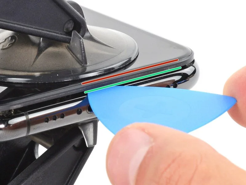
- Employing a heated iOpener, carefully guide it between the Anti-Clamp’s securing arms.Alternative heating methods, such as a hair dryer, heat gun, or hot plate, are permissible; however, exercise caution to prevent damage to the display assembly or internal battery due to excessive temperatures.Position the iOpener along the lower edge of the iPhone’s chassis, ensuring it rests flatly.
Allow a sixty-second interval to permit the adhesive bond to weaken and create a discernible separation. - Introduce an opening tool into the newly formed space situated beneath the display and the surrounding plastic frame, avoiding direct contact with the screen’s surface.Should the Anti-Clamp fail to generate a satisfactory gap, increase the applied heat and rotate the handle by ninety degrees.Incremental handle rotations, limited to ninety-degree increments, are recommended, with a one-minute pause between each adjustment.
- Rely on the Anti-Clamp’s mechanism and time to facilitate the separation process, rather than applying excessive force.
- Proceed past the subsequent three procedural steps.
- The iOpener’s thermal application should be precise to avoid component degradation.A sixty-second waiting period is crucial for optimal adhesive release.The opening tool must be inserted carefully to prevent screen damage.
- Handle rotations should be gradual to prevent stress on the device's housing.
- Adhesive softening requires patience; allow sufficient time for the process to complete.
Step 7 | Heat the lower edge of the phone
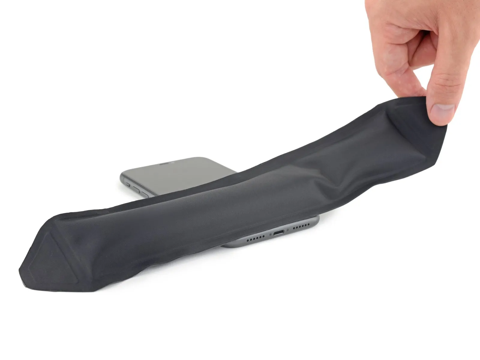
Applying warmth to the iPhone's bottom edge facilitates separation of the display from its frame by reducing the adhesive's hold.
A hairdryer is a suitable tool for this process.Alternatively, a heat gun can be employed.The iOpener provides another option for generating heat.Direct the heat source towards the lower edge of the iPhone's casing.Maintain the heat application for approximately one minute.This duration allows the adhesive to become pliable, easing the opening procedure.Care must be taken to avoid excessive heat, which could damage internal components.
Step 8
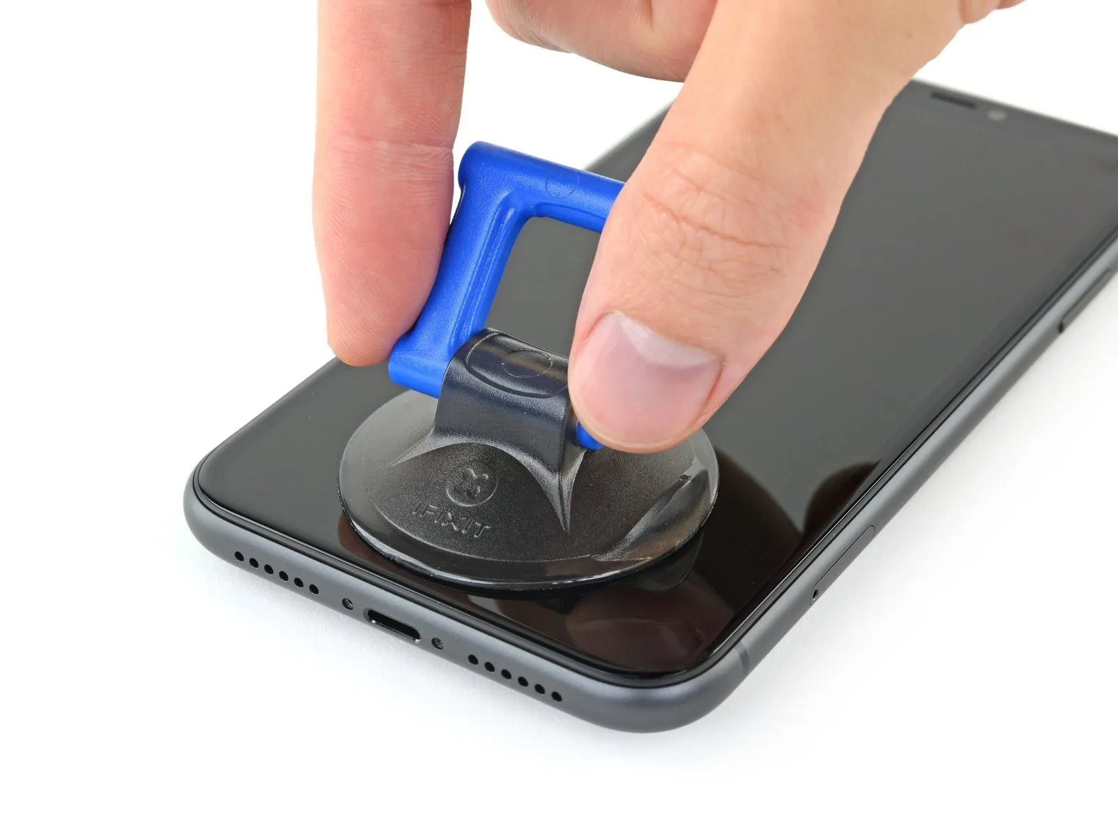
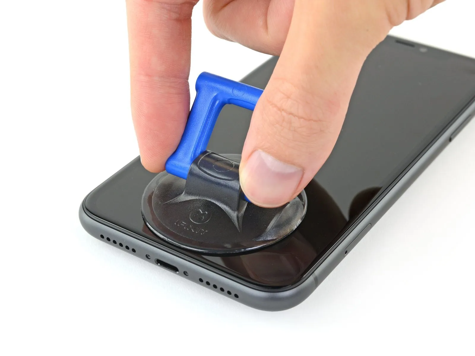
To utilize a solitary suction handle, position it against the lower perimeter of the device's frame, ensuring the curved glass surface remains untouched.
Step 9 | Lift the display slightly
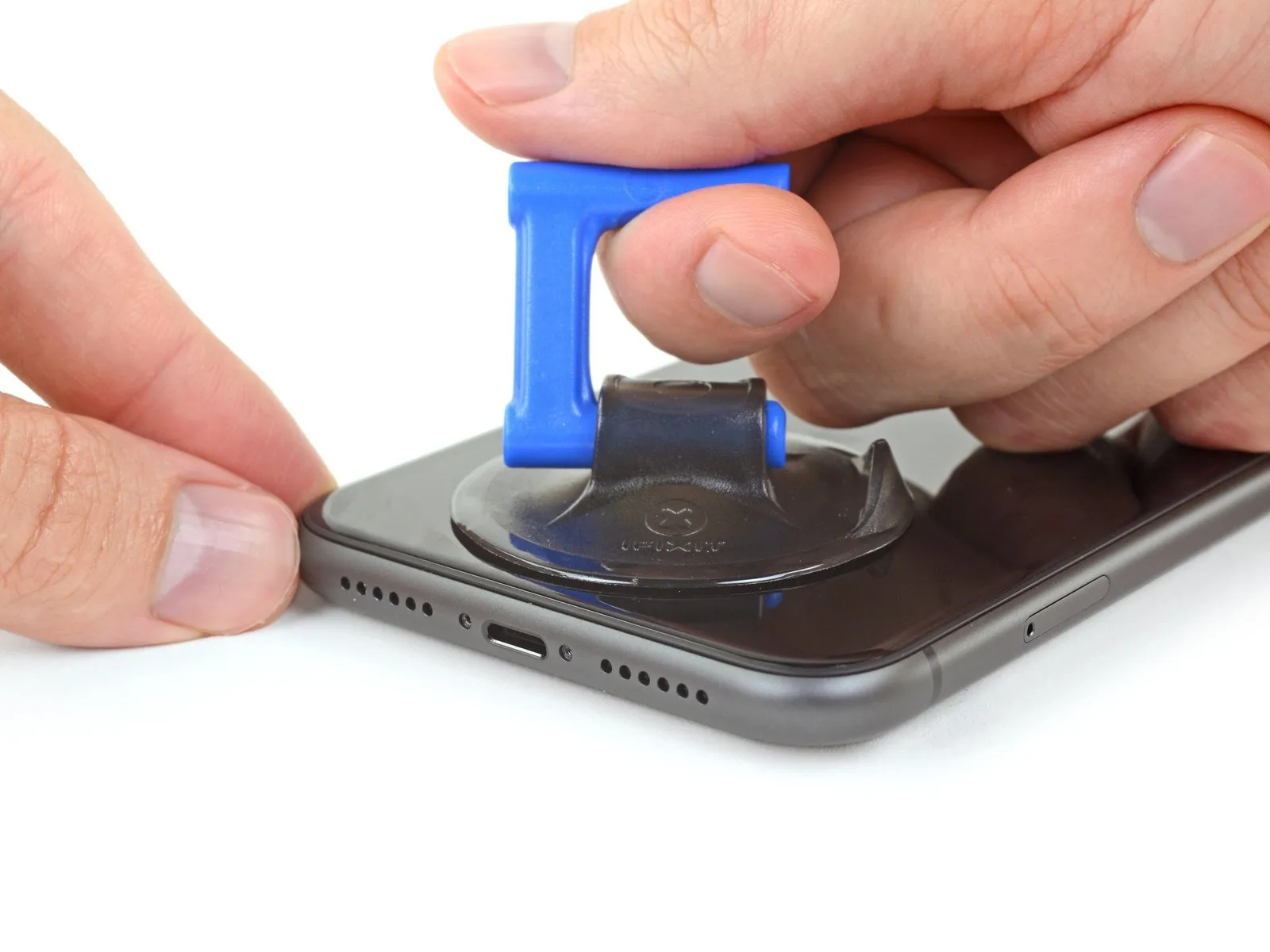
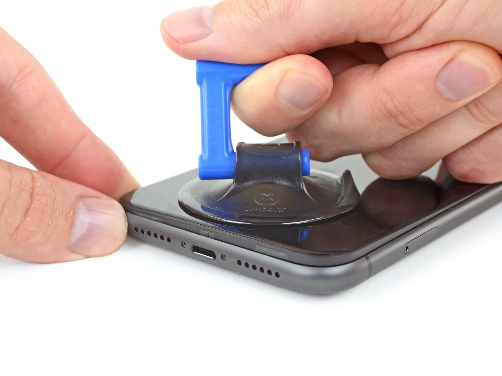
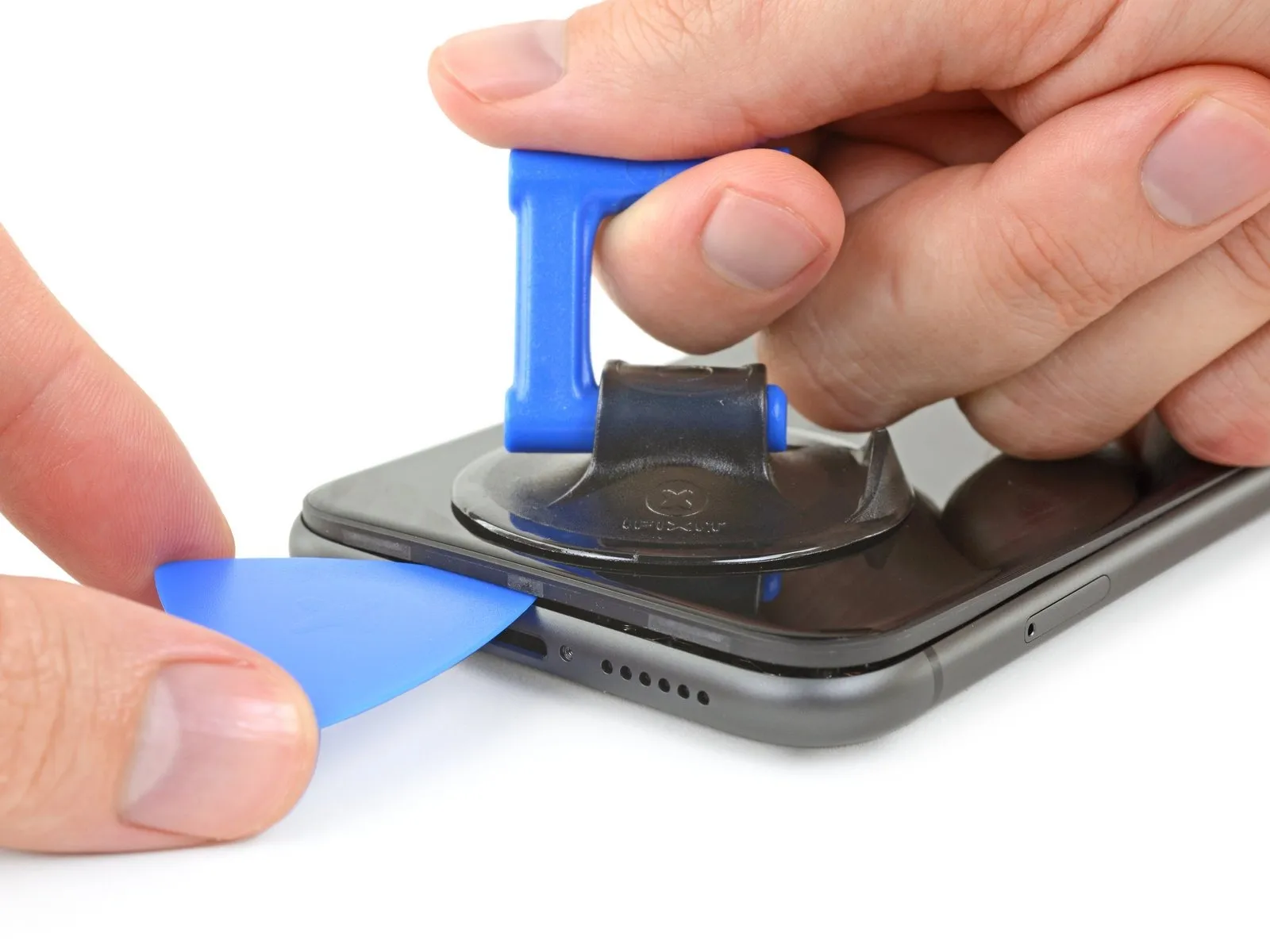
- Apply steady, forceful upward pressure to the suction cup to generate a minimal separation between the device's front panel and its rear enclosure.
- Carefully slide an opening tool into the space formed beneath the display screen and surrounding plastic trim, ensuring it does not contact the screen's surface directly.
- Due to the robust nature of the waterproof sealant securing the display, a considerable amount of force may be required to initially create this separation; if difficulty arises, applying additional heat and gently oscillating the screen will help to soften the adhesive, facilitating tool insertion.
Step 10 | Separate the screen adhesive
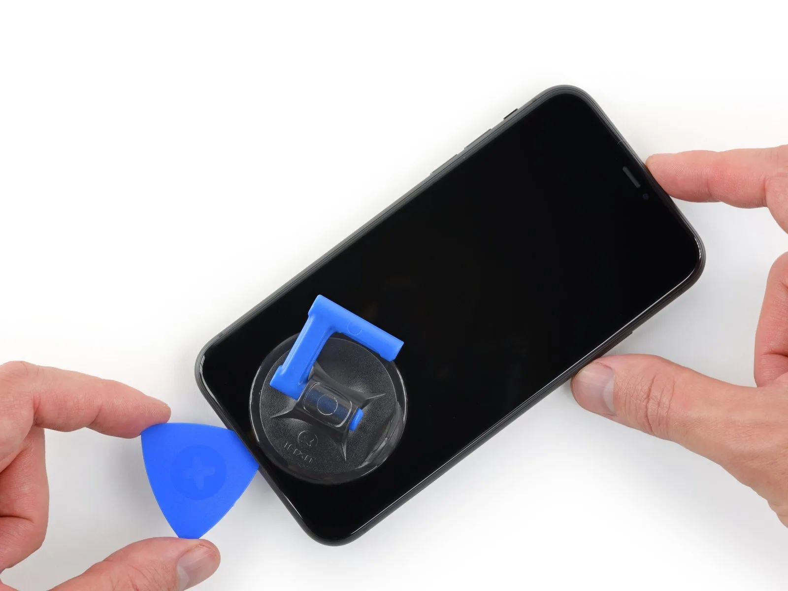
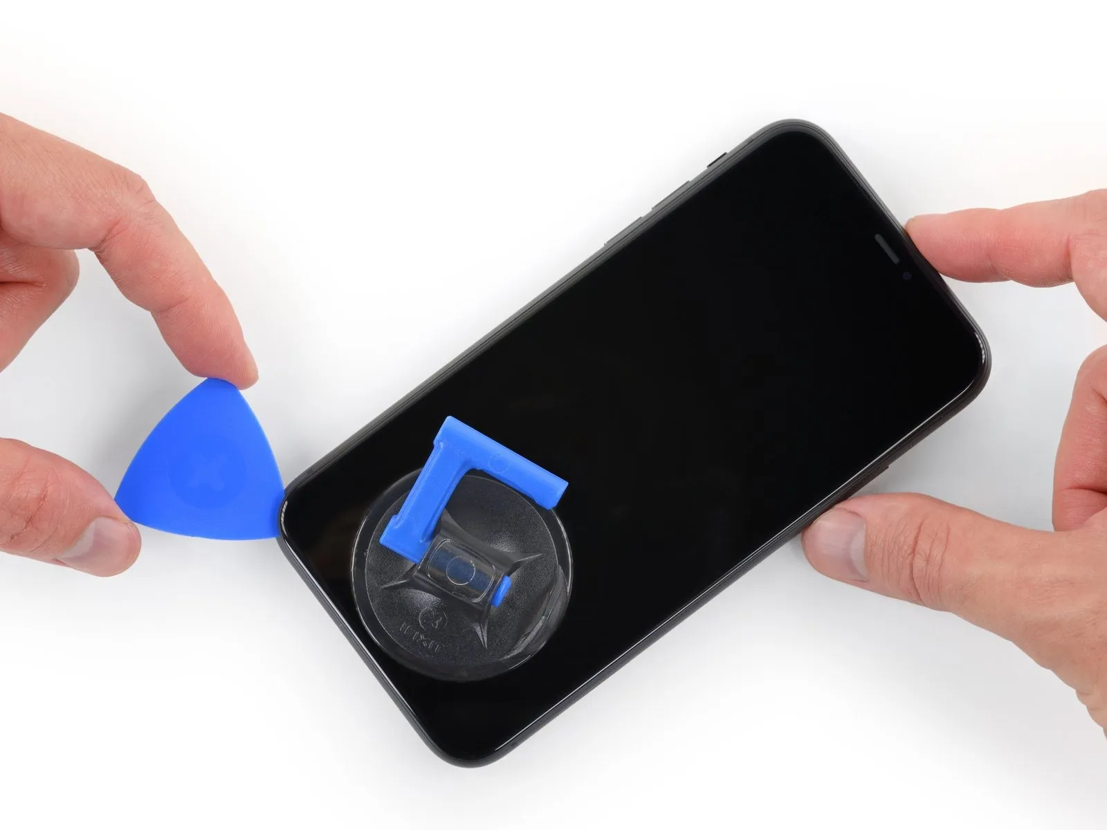
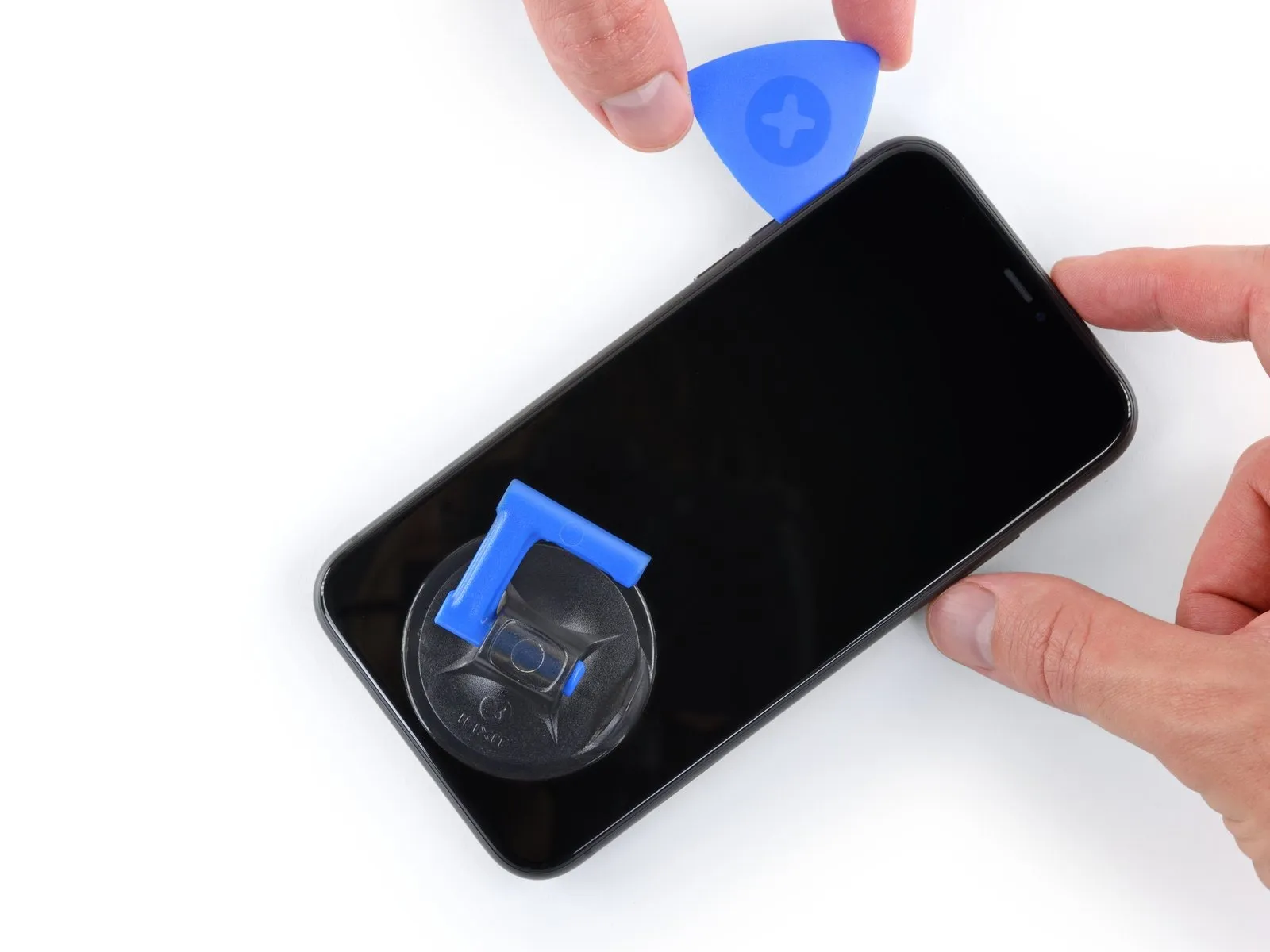
- Employ an opening pick to maneuver along the lower-left perimeter of the iPhone, progressing upward along the left side to sever the adhesive securing the display assembly.
- Ensure the pick's insertion depth remains below 3 mmto prevent potential harm to delicate internal components.
Step 11 | Screen information
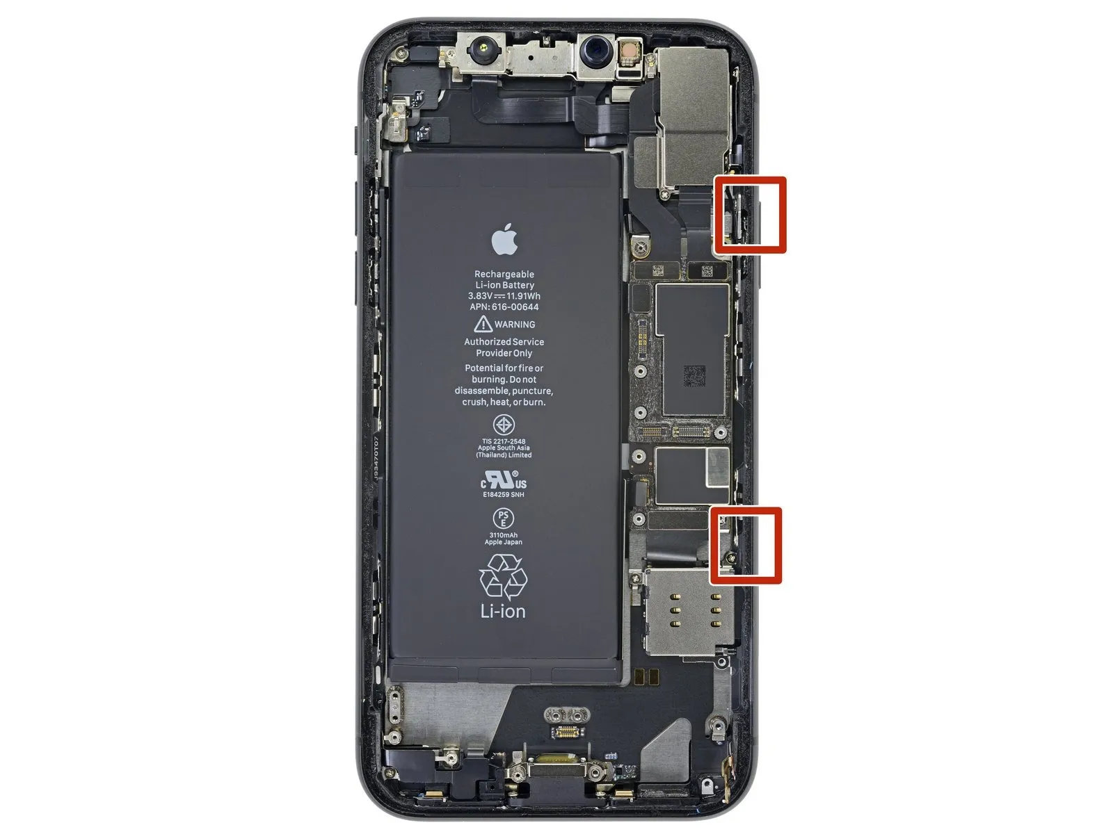
Fragile wiring is situated along the iPhone's right side; avoid inserting any tools in this area to prevent cable damage.
Step 12
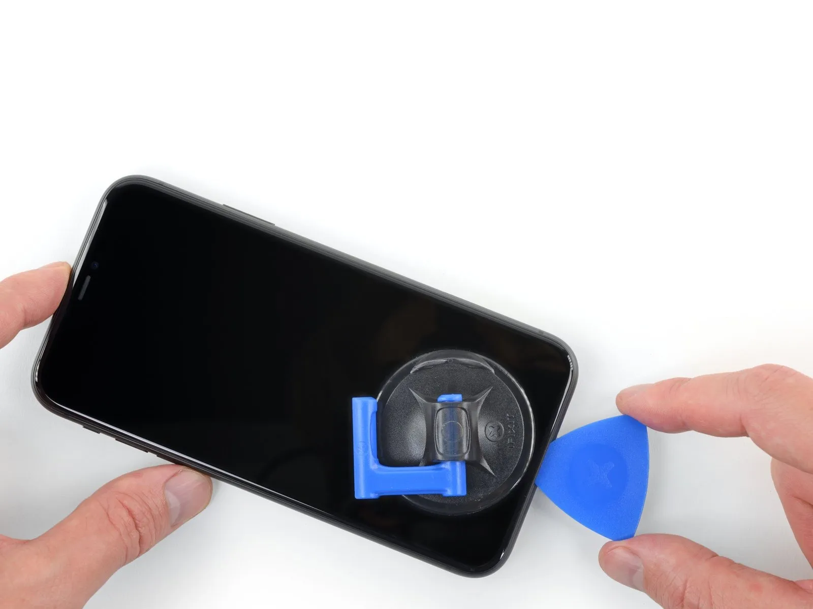
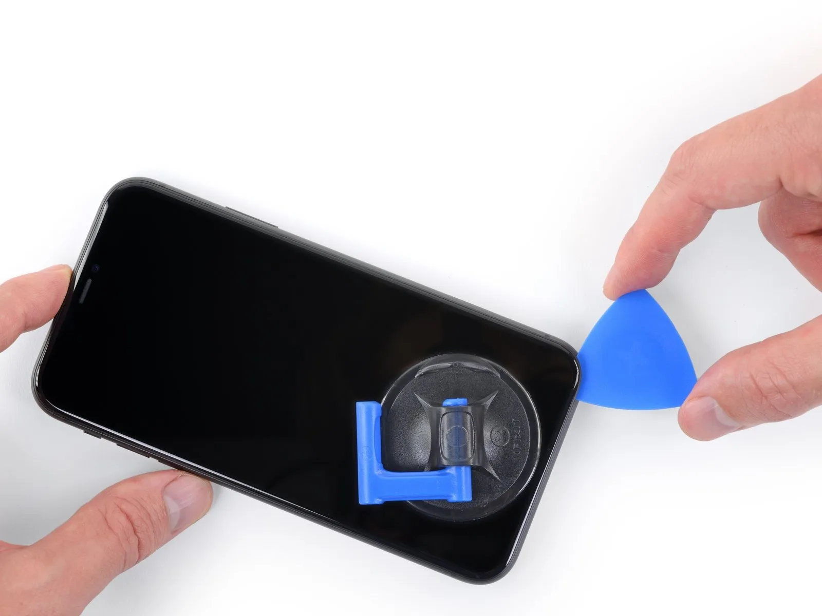
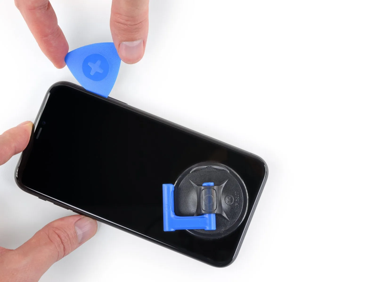
- To proceed with separating the adhesive, re-position your opening pick along the lower edge of the iPhone's display, then advance it upwards along the right side.
- Ensure the pick's insertion depth remains limited to a maximum of 3 millimeters to prevent potential damage to the delicate display cable connections.Exceeding this 3-millimeter depth poses a risk of injury to the display's internal wiring.Maintaining a shallow insertion depth, no greater than 3 mm, is crucial for safeguarding the display cables during separation.
Step 13
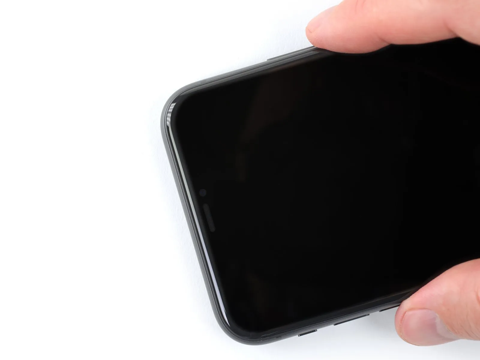
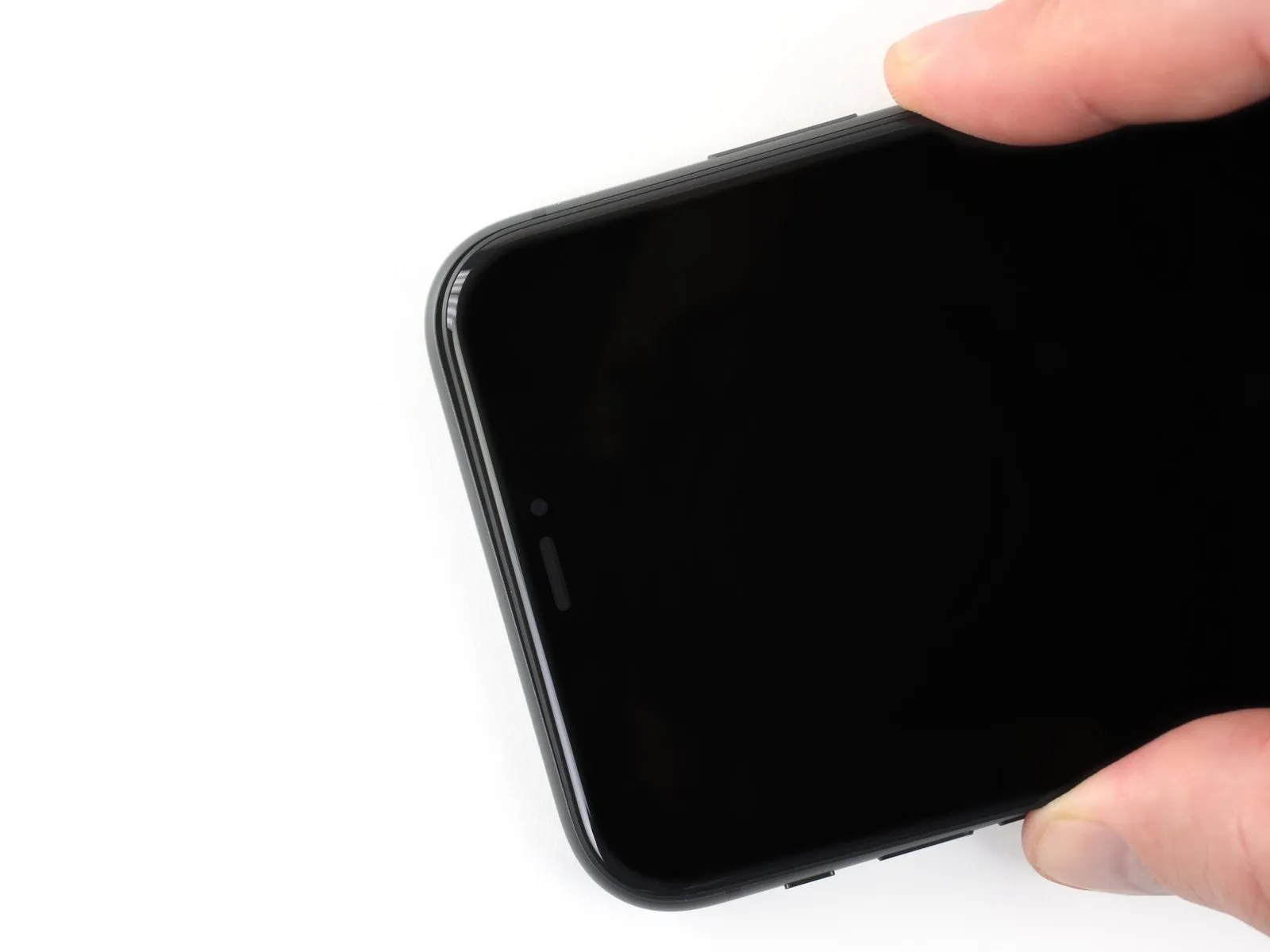
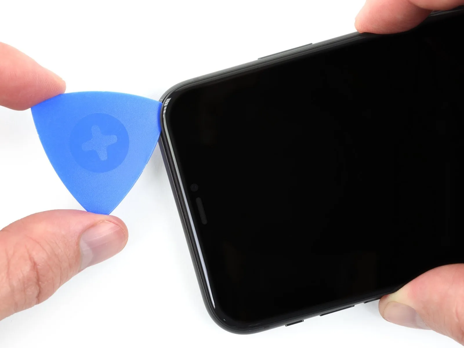
- Adhesive and retaining clips together fasten the display's upper boundary.
To disengage the display, apply a slight downward force to its right side, moving towards the Lightning connector. - Position a specialized opening tool within the upper-rightmost corner of the device's casing.
Step 14
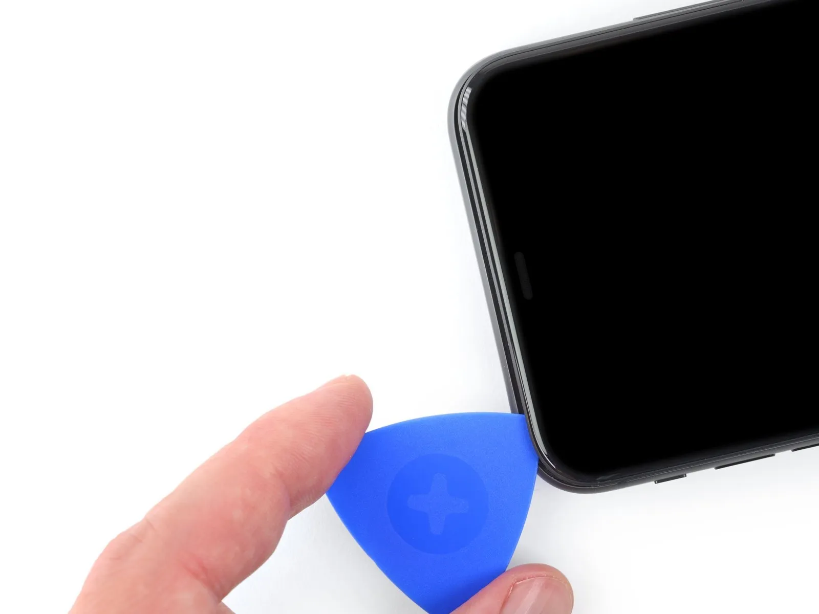
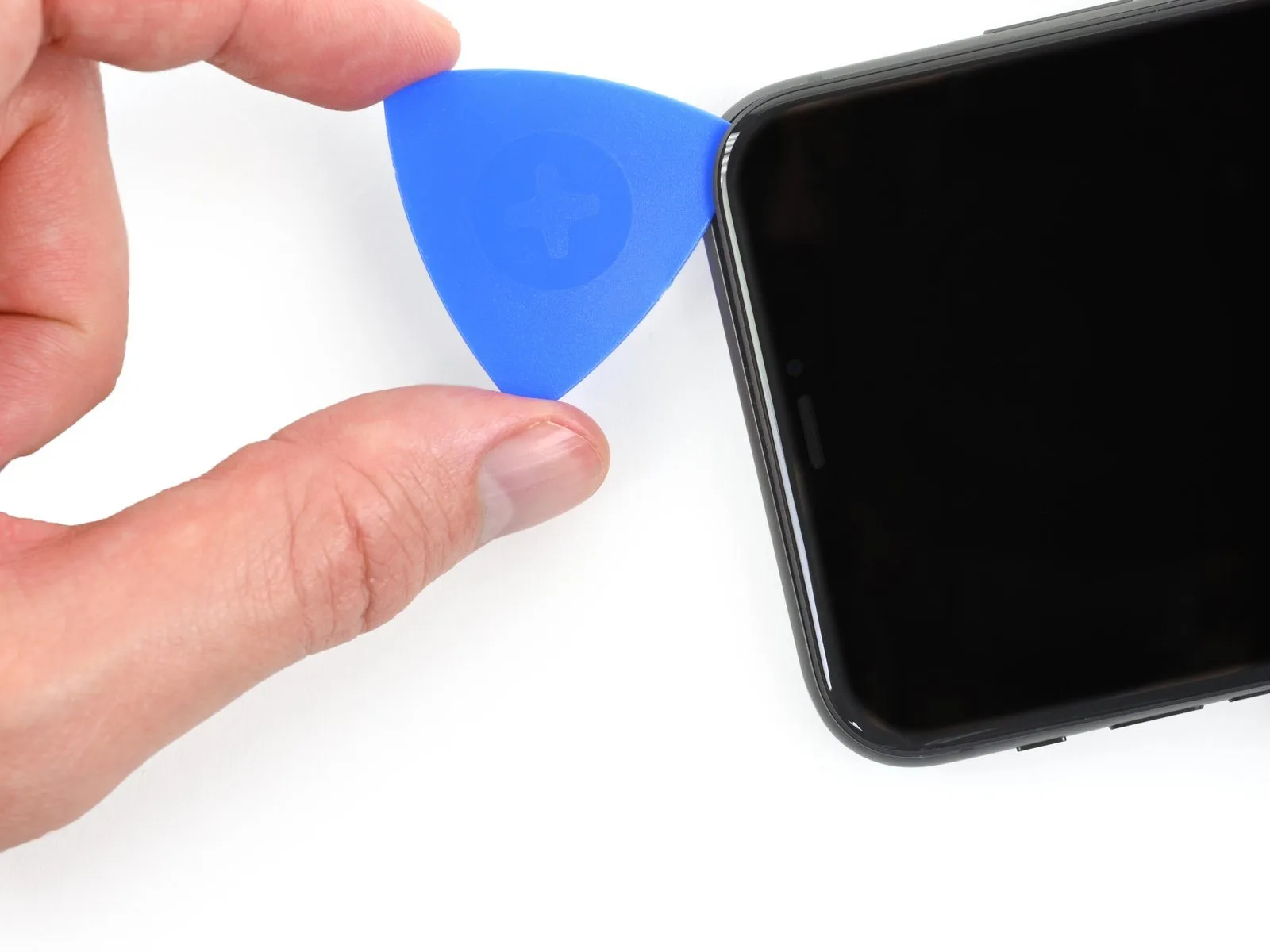
- Maintain downward pressure on the display assembly, directing it towards the Lightning connector, until a sufficient separation is achieved to accommodate the use of a prying tool.
Employ the prying tool and maneuver it to the upper-left edge of the device to sever any residual adhesive bonds holding the display in place.
Limit the insertion depth of the prying tool to a maximum of 3 millimeters to prevent potential harm to the Face ID sensor array.
Step 15 | Remove the suction cup
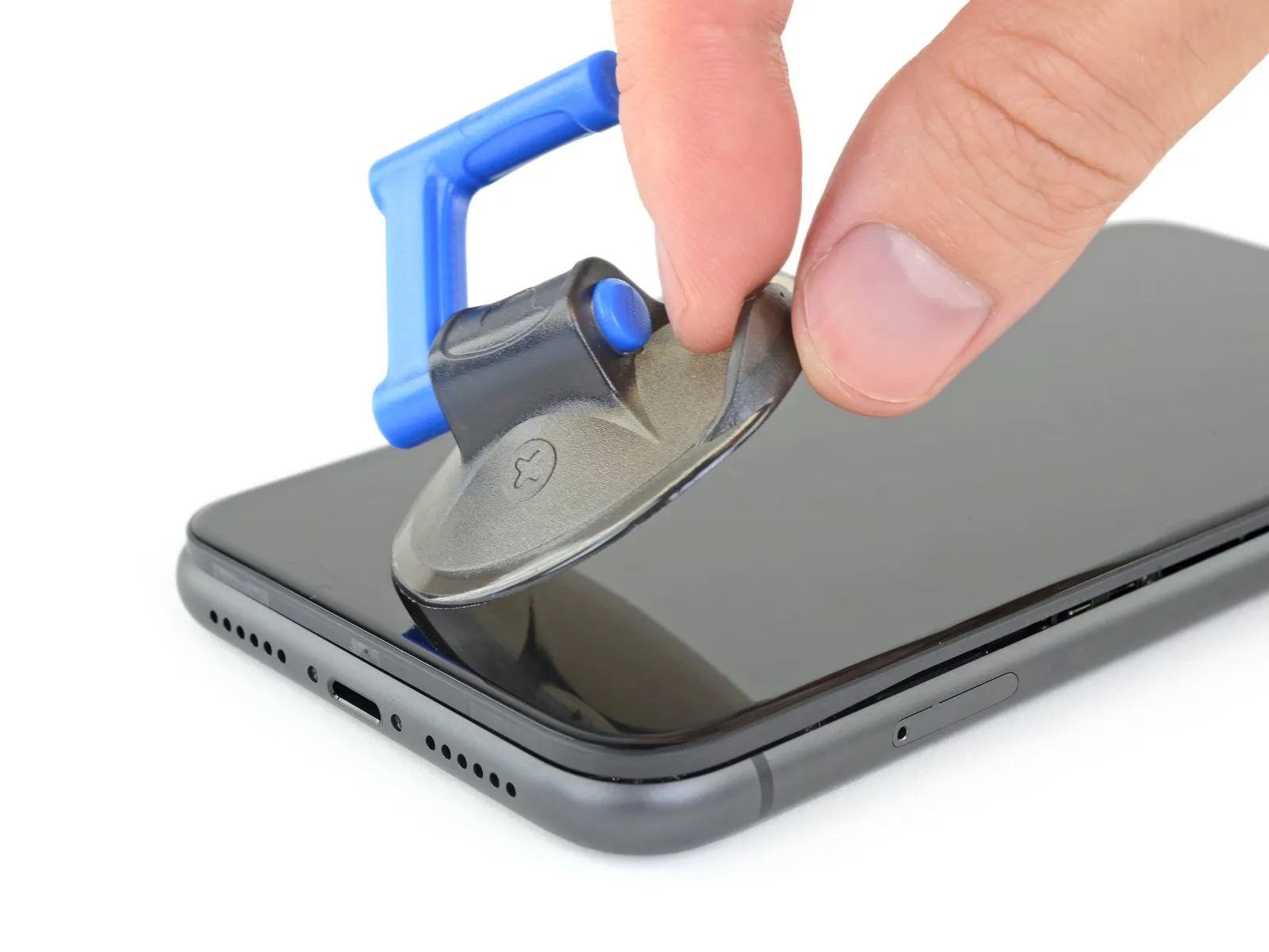
- To release the suction cup and separate it from the front panel, apply traction by grasping and pulling the small protruding portion.
Step 16 | Open the iPhone
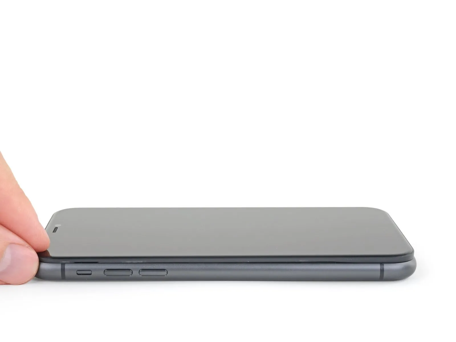
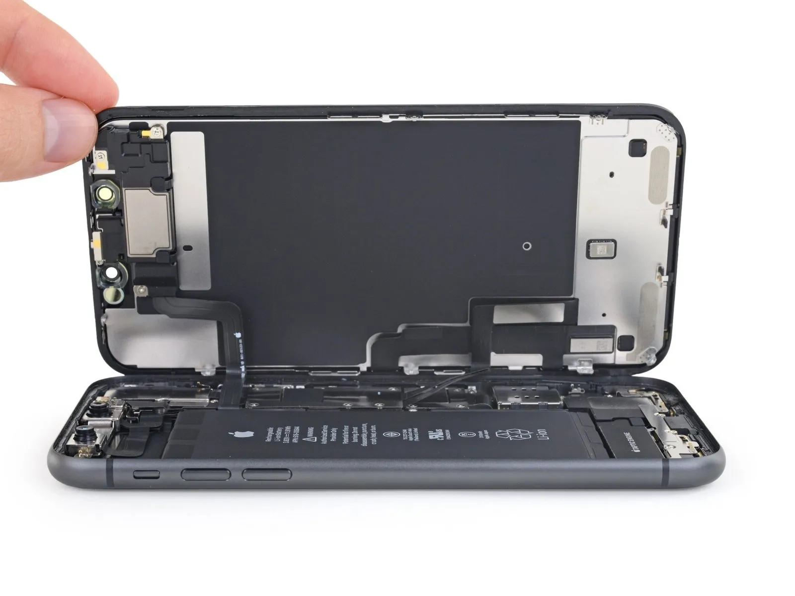
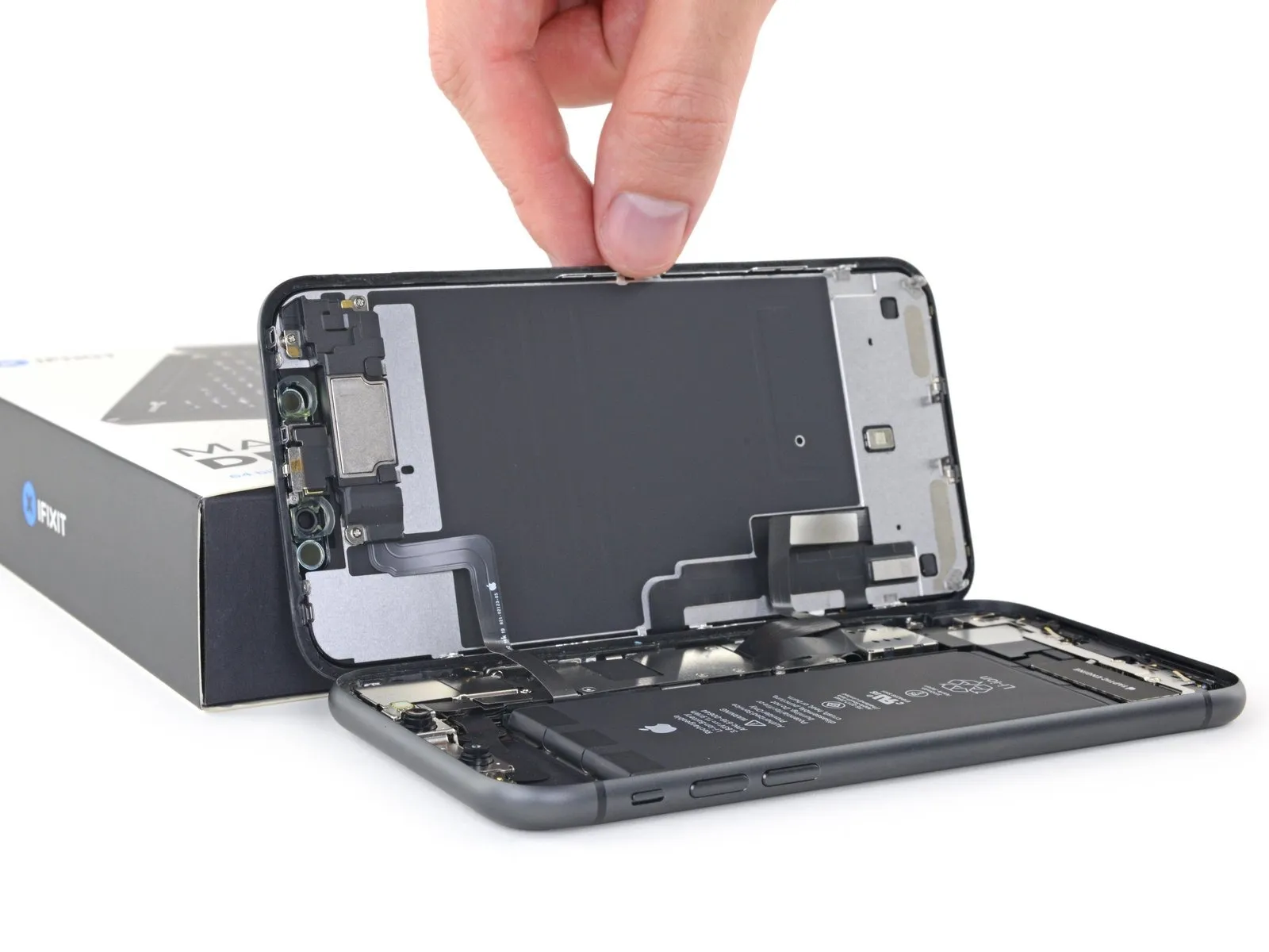
- To access the iPhone's internal components, initiate the opening process by pivoting the display upwards, starting from the left edge, mimicking the action of opening a book's cover.
Avoid completely detaching the display at this stage, because multiple delicate ribbon cables maintain its electrical connection to the iPhone's logic board.
Secure the lifted display in an upright position using a stable support.
When reassembling the device, position the display, ensuring the top edge clips are properly aligned, and then gently apply pressure to the top edge before securing the remainder of the display; if resistance is encountered, inspect the display's perimeter clips for any deformation that might impede proper engagement.
Step 17 | Display Assembly
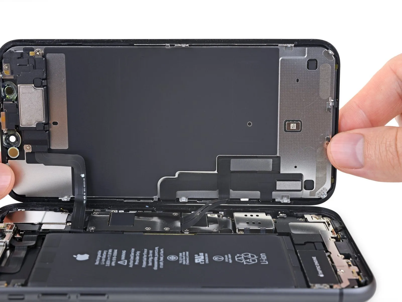
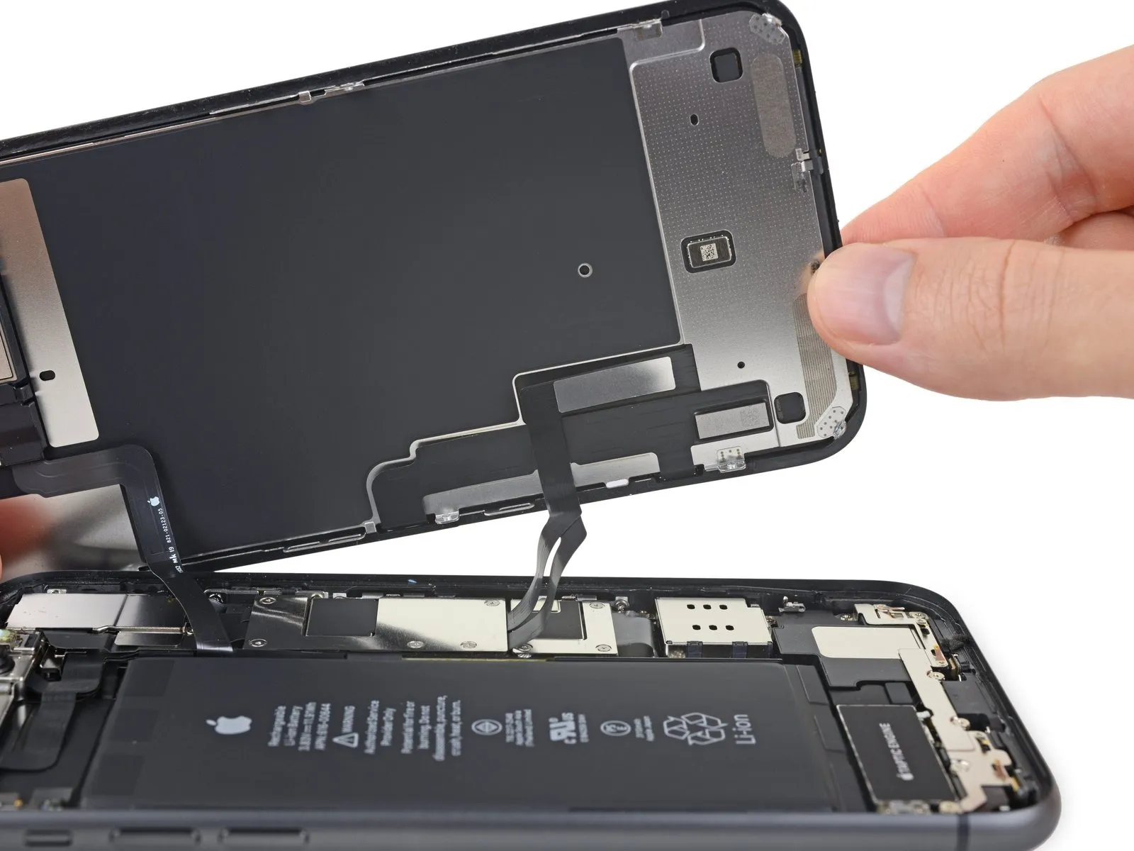
For the subsequent screw removal, elevate the display's bottom portion to create an angled position.
Exercise caution to prevent damage or separation of the delicate display cables.The display cables are susceptible to stress and potential tearing.Handle the display with care to avoid compromising the integrity of the display cables.
Step 18 | Unscrew the battery connector cover
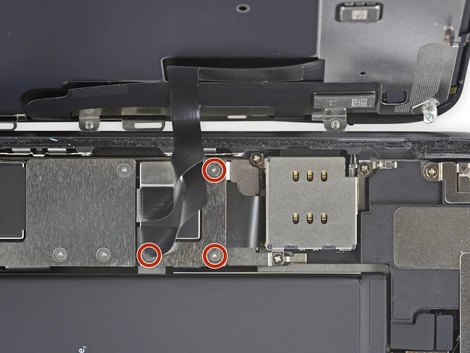
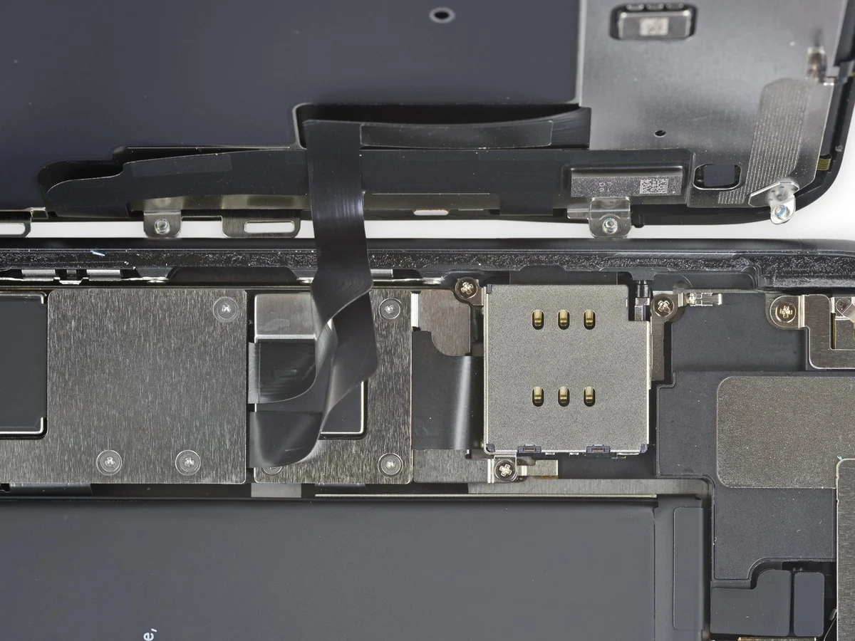
- Employ a Y000-type screwdriver to detach the three screws.The screws fastening the battery connector bracket each measure 1.1 millimeters in length.Carefully monitor the location of each screw throughout the repair process to ensure correct reinstallation.
Prior to permanently reattaching the display, it is advisable to activate your iPhone and verify all operational capabilities.
Completely deactivate the iPhone before proceeding with subsequent repair steps following the functional test.
Step 19 | Remove the battery connector cover
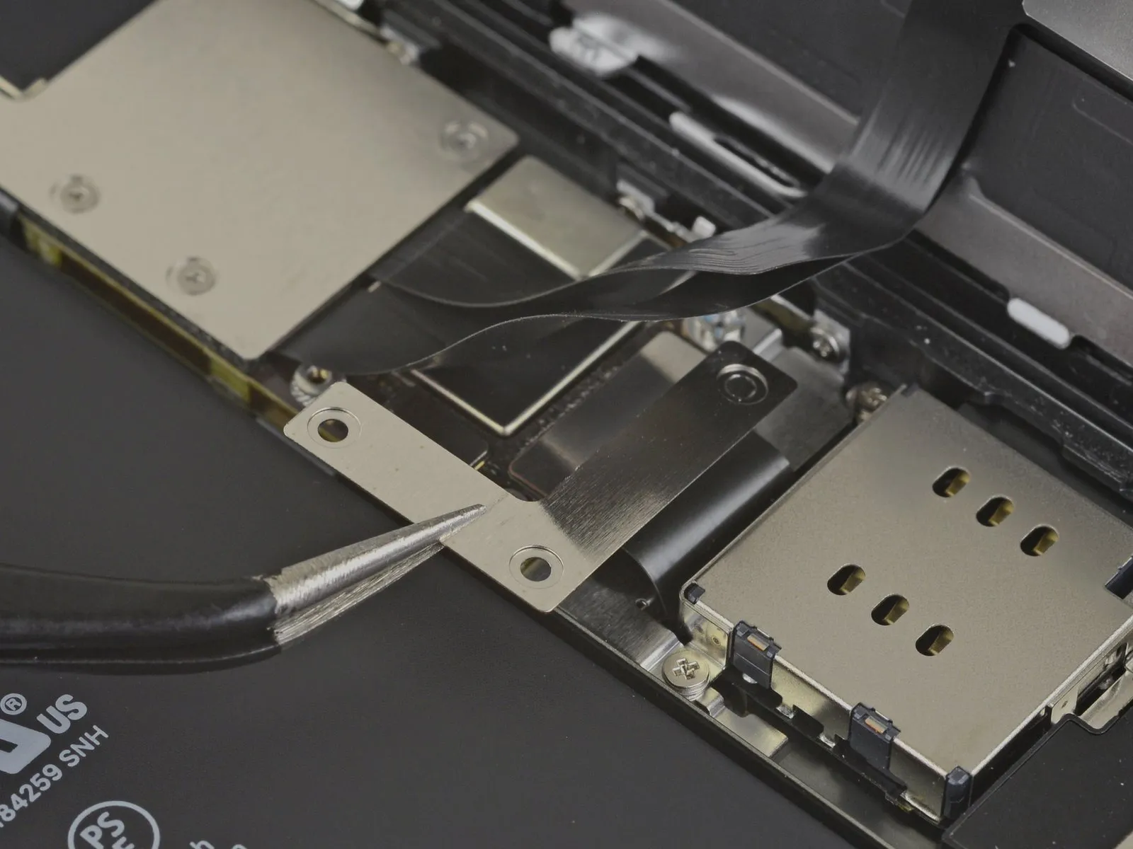
Detach the bracket.
Step 20 | Disconnect the battery
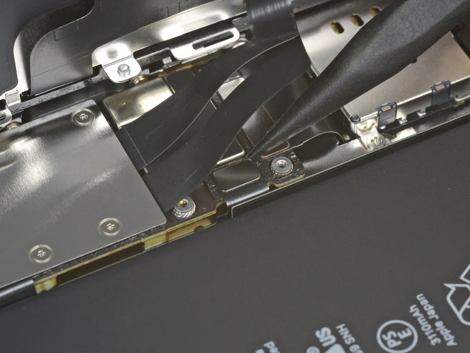
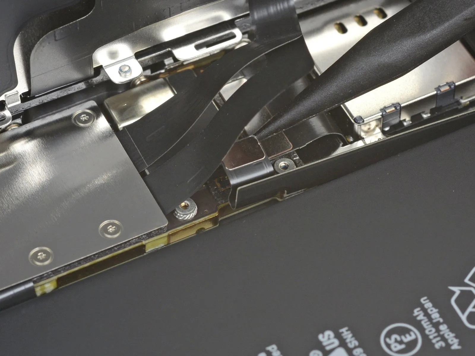
- Employ a spudger tool or a clean fingernail to lift the battery connector's retaining clip away from its corresponding receptacle on the logic board.
Exercise caution to avoid harming the black silicone seals that encircle this connector and others, as they offer supplemental defense against water and particulate matter ingress.
Slightly deflect the connector outward from the logic board's surface to inhibit unintended contact with the socket.
Step 21 | Unscrew the logic board cover screws
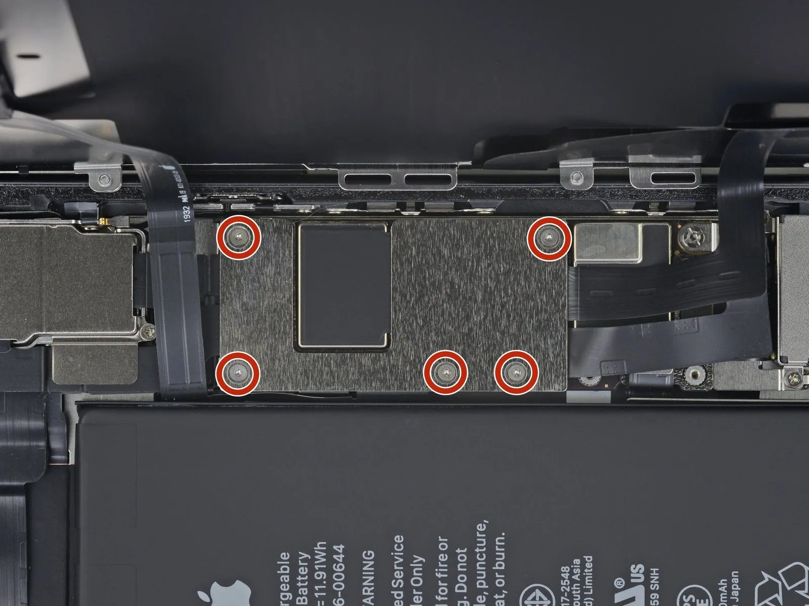
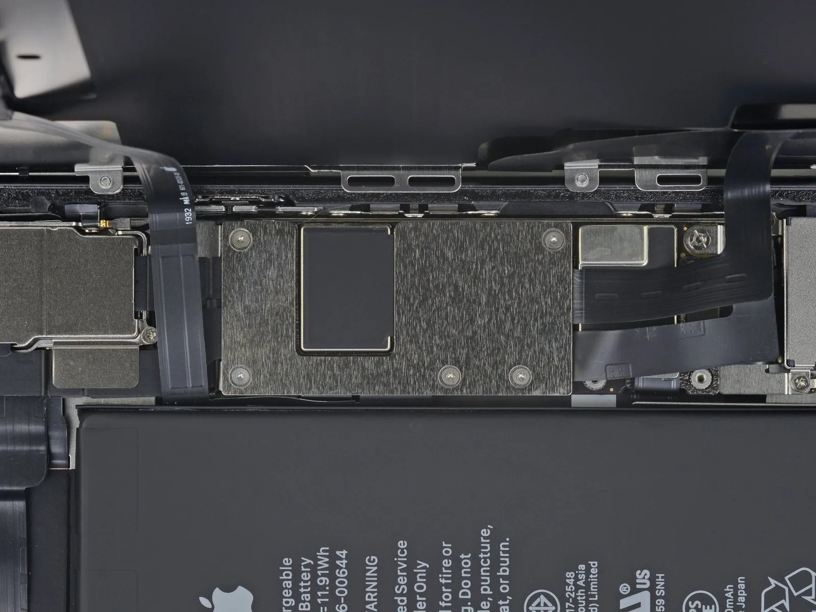
Employ a Y000 driver for the extraction of the five screws.The screws, each measuring 1.1 mm in diameter, fasten the logic board cover bracket.Removal of these fasteners is necessary to access the bracket's securing mechanism.A Y000 driver is the appropriate tool to apply the necessary torque.These 1.1 mm screws hold the bracket in place, requiring careful removal with a Y000 driver.
Step 22 | Remove the logic board cover bracket
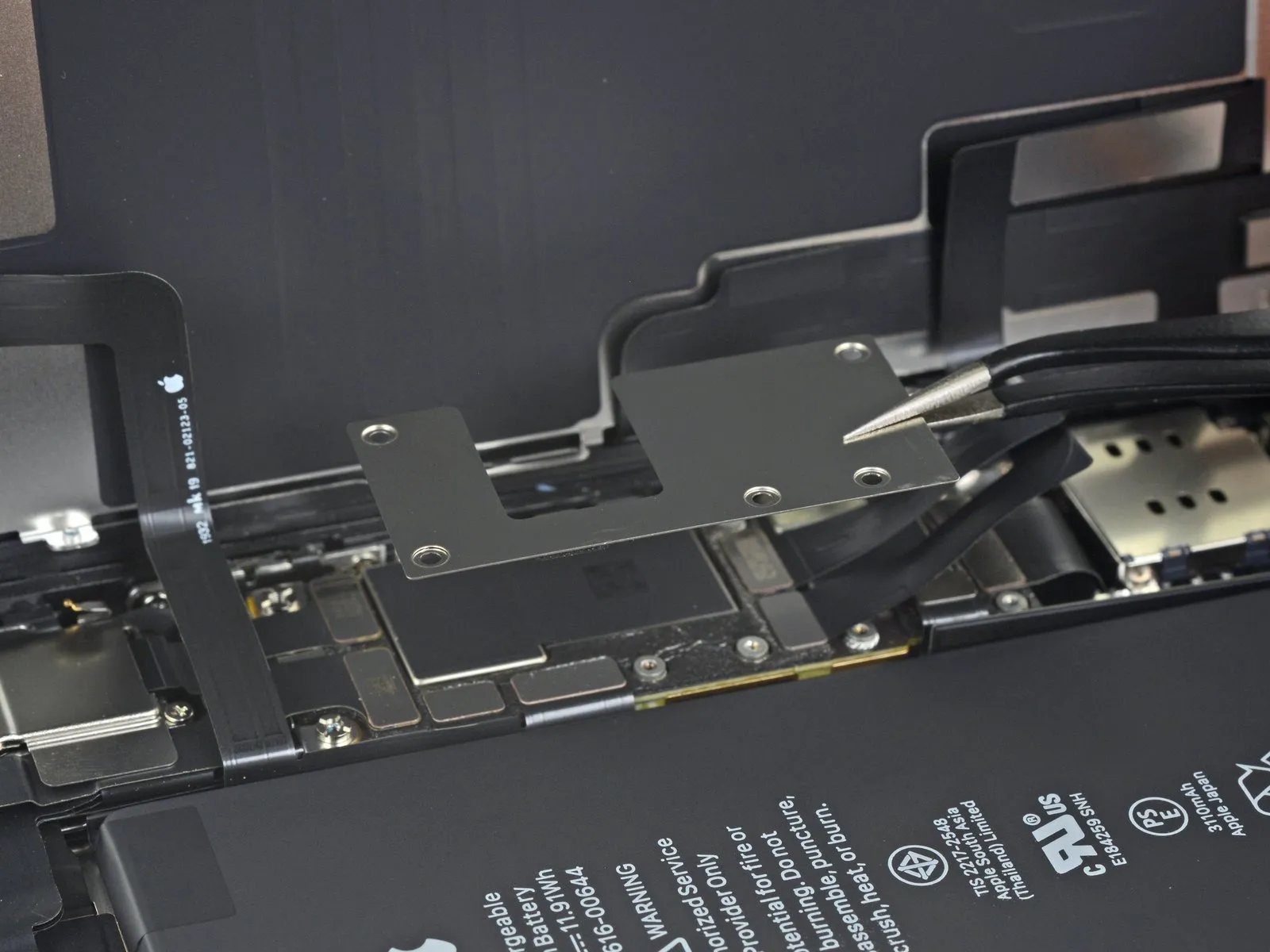
Detach the clamp.
Step 23 | Disconnect the display
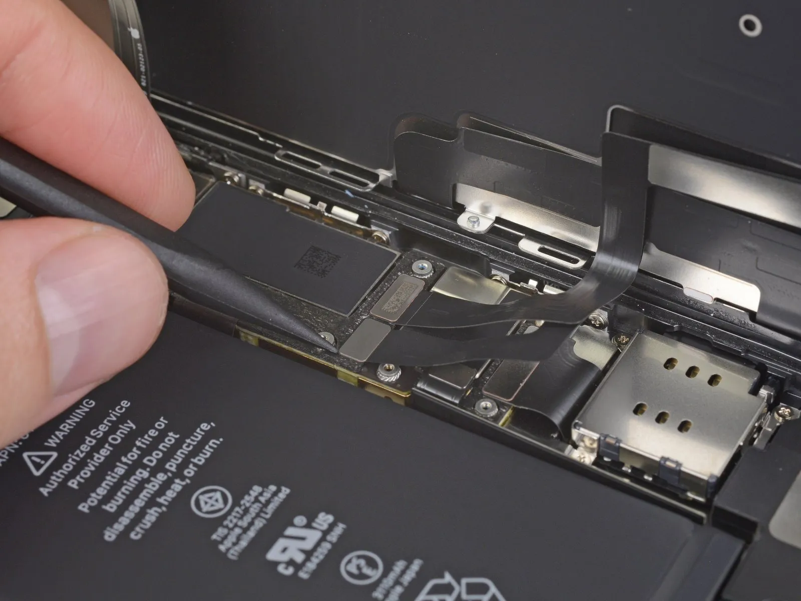
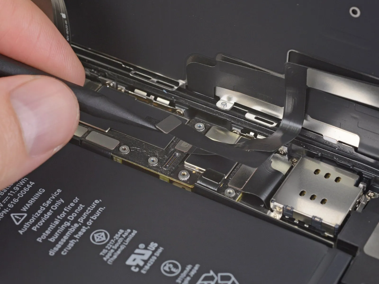
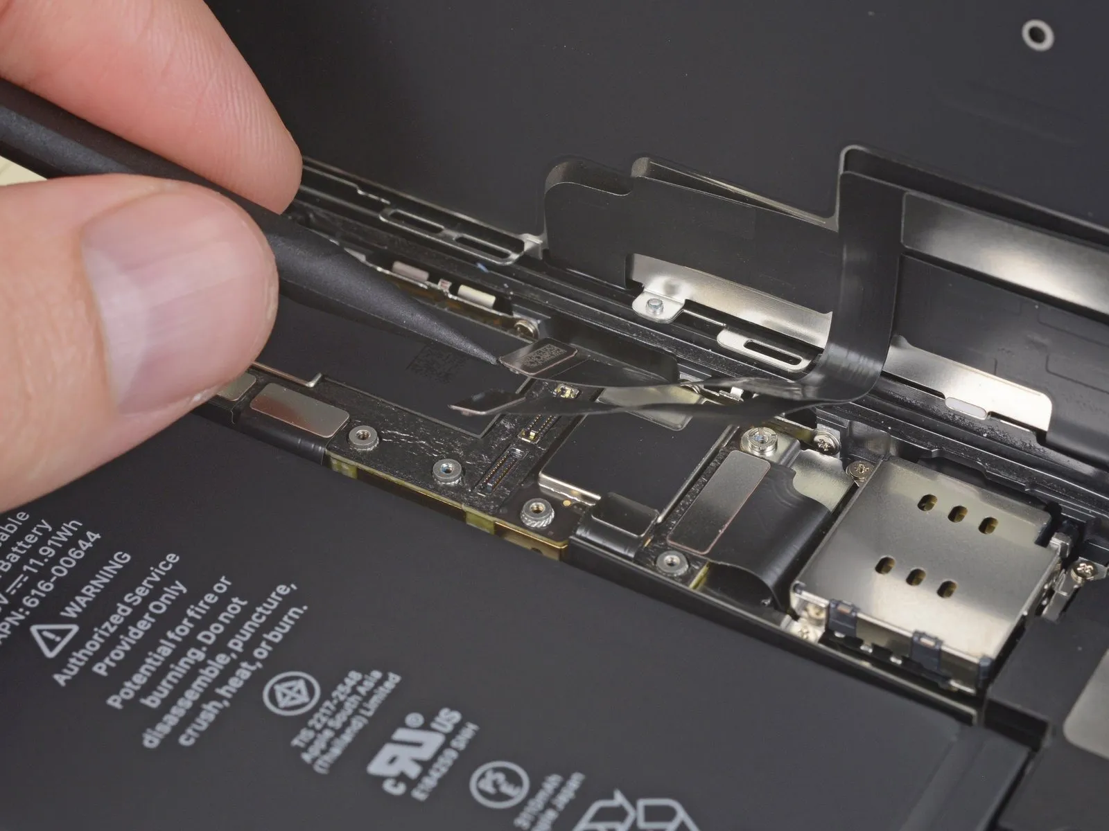
- Employ a spudger tool, or carefully utilize a fingernail, to release the LCD panel cable's connection.The connector securing the digitizer, positioned adjacent to the LCD panel connector, must also be detached.Applying gentle force with a spudger or fingernail facilitates the separation of the LCD panel cable connector.To ensure complete disconnection, the digitizer connector, located in close proximity, requires similar attention.A spudger's tip or a fingernail can be used to carefully pry the LCD panel cable connector free from its socket.
- Following the LCD panel cable disconnection, proceed to detach the digitizer connector, which is situated nearby.
Step 24 | Disconnect the front sensors
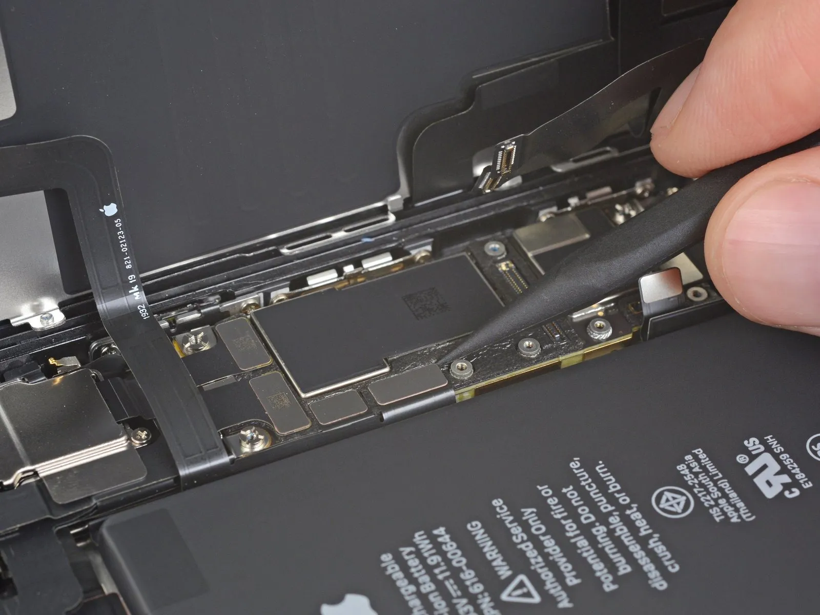
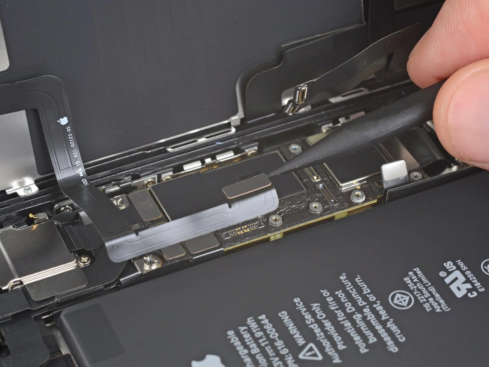
Employing the tip of a spudger tool, or a fingernail, facilitates the separation of the front panel sensor assembly's connector.The connector linking the front panel sensor assembly requires disconnection via a spudger's pointed end, or a fingernail's edge.To release the front panel sensor assembly connector, utilize the pointed tip of a spudger, or carefully leverage a fingernail.A spudger's pointed tip, or the edge of a fingernail, can be used to detach the connector associated with the front panel sensor assembly.For disconnecting the front panel sensor assembly connector, a spudger's point or a fingernail's edge provides a suitable method.
Step 25 | Remove the display assembly
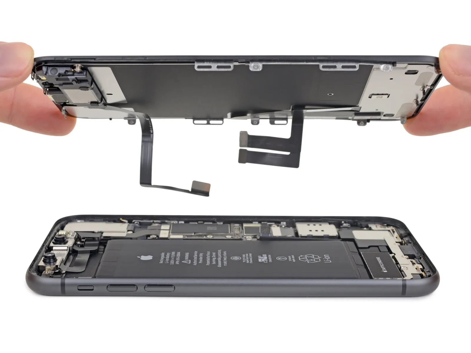
- Detach the display unit from the device.
- If a replacement of the waterproof adhesive sealant bordering the display is desired, halt the reassembly process at this juncture.
Step 26 | Remove the lower bracket screws
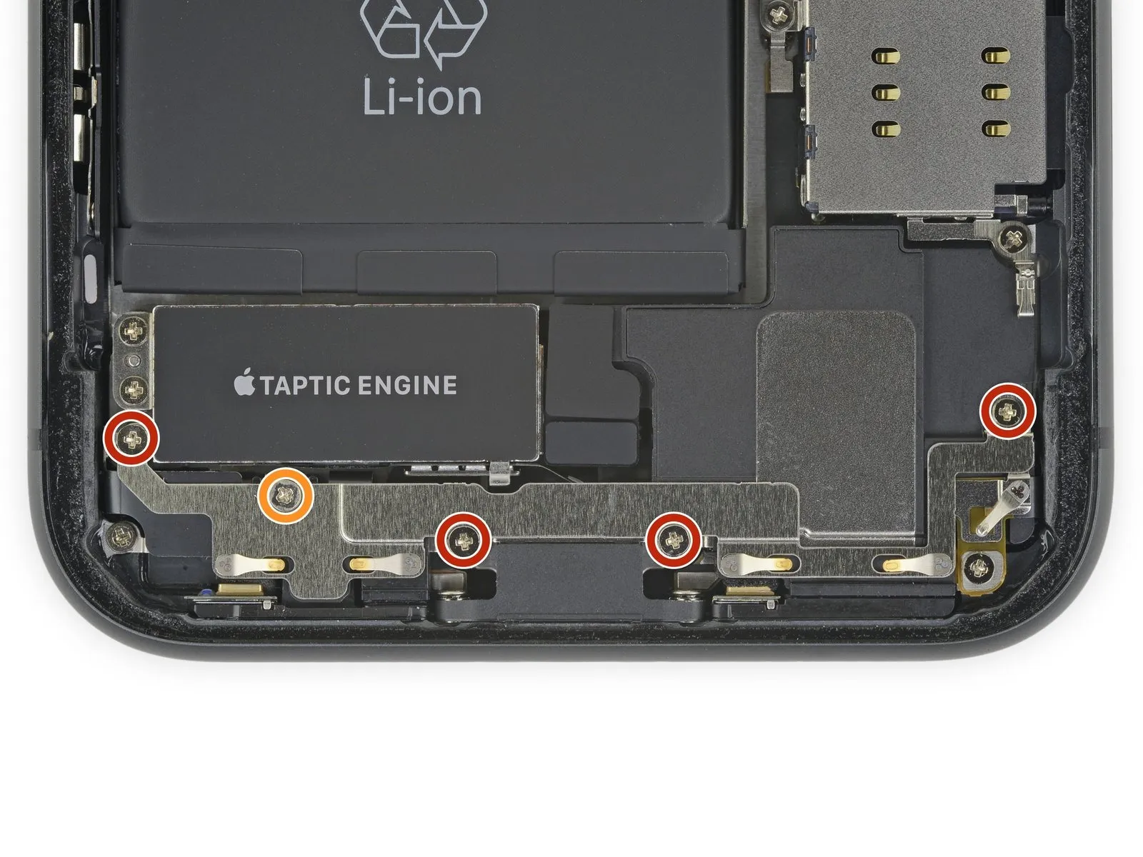
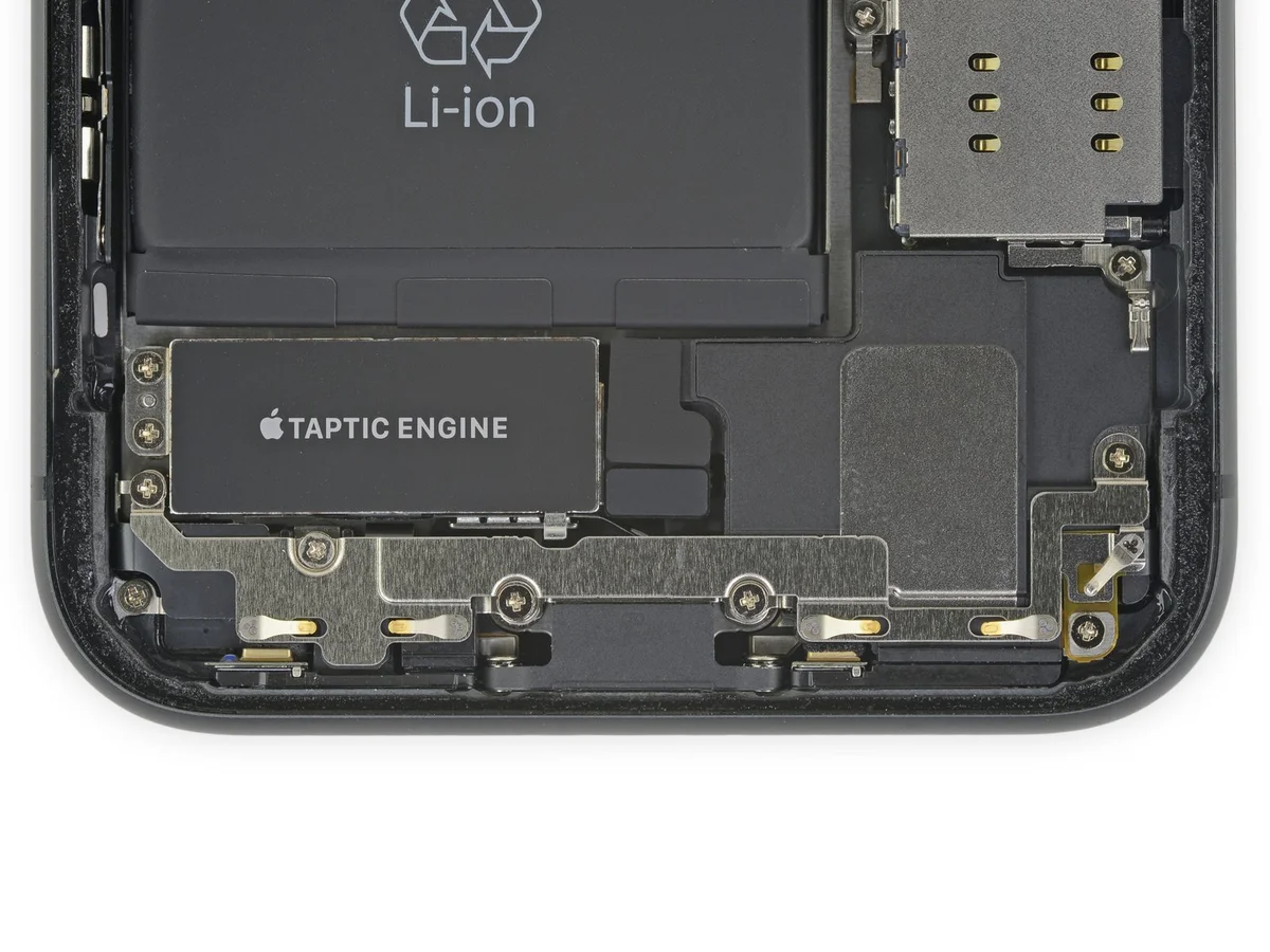
- Employing a Phillips head screwdriver, detach the five screws that fasten the bracket located beneath the Taptic engine and speaker assembly.The bracket is secured with four screws, each measuring 1.6 millimeters in diameter.A single screw, with a 1.3-millimeter diameter, is also part of the bracket's fastening mechanism.
- Carefully unscrew and retain these fasteners for reassembly.
- Ensure the correct screw is used for each location to avoid damage to the threads.
Step 27 | Remove the lower bracket
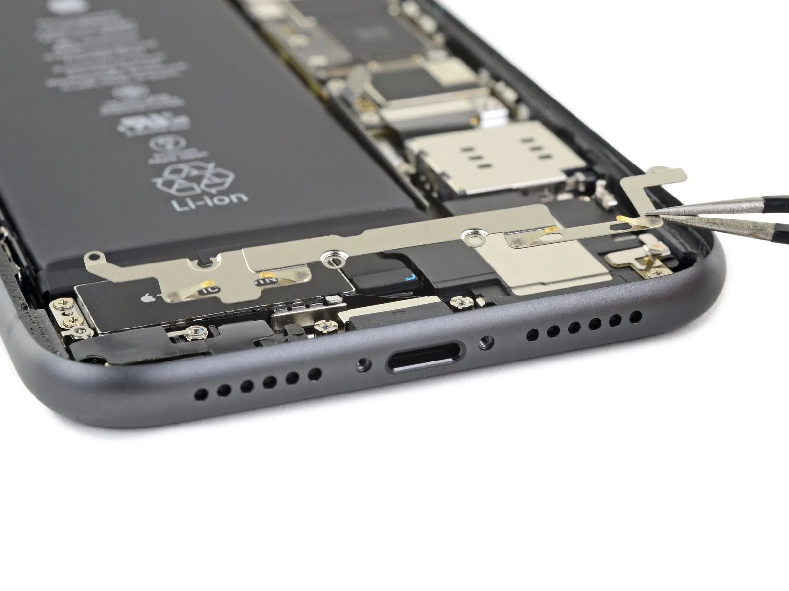
Detach the component situated at the base of the assembly.
Step 28 | Remove the Taptic Engine connector tape
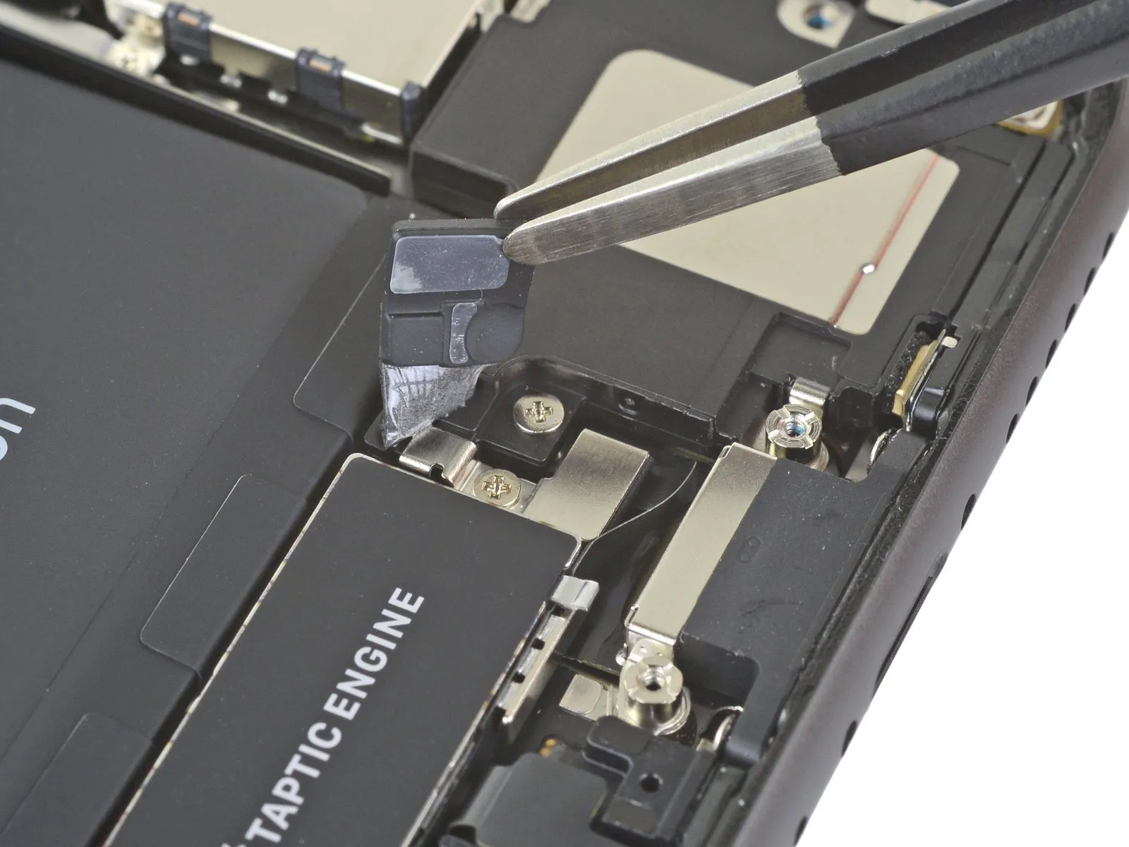
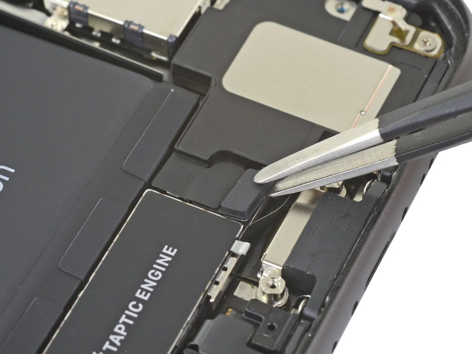
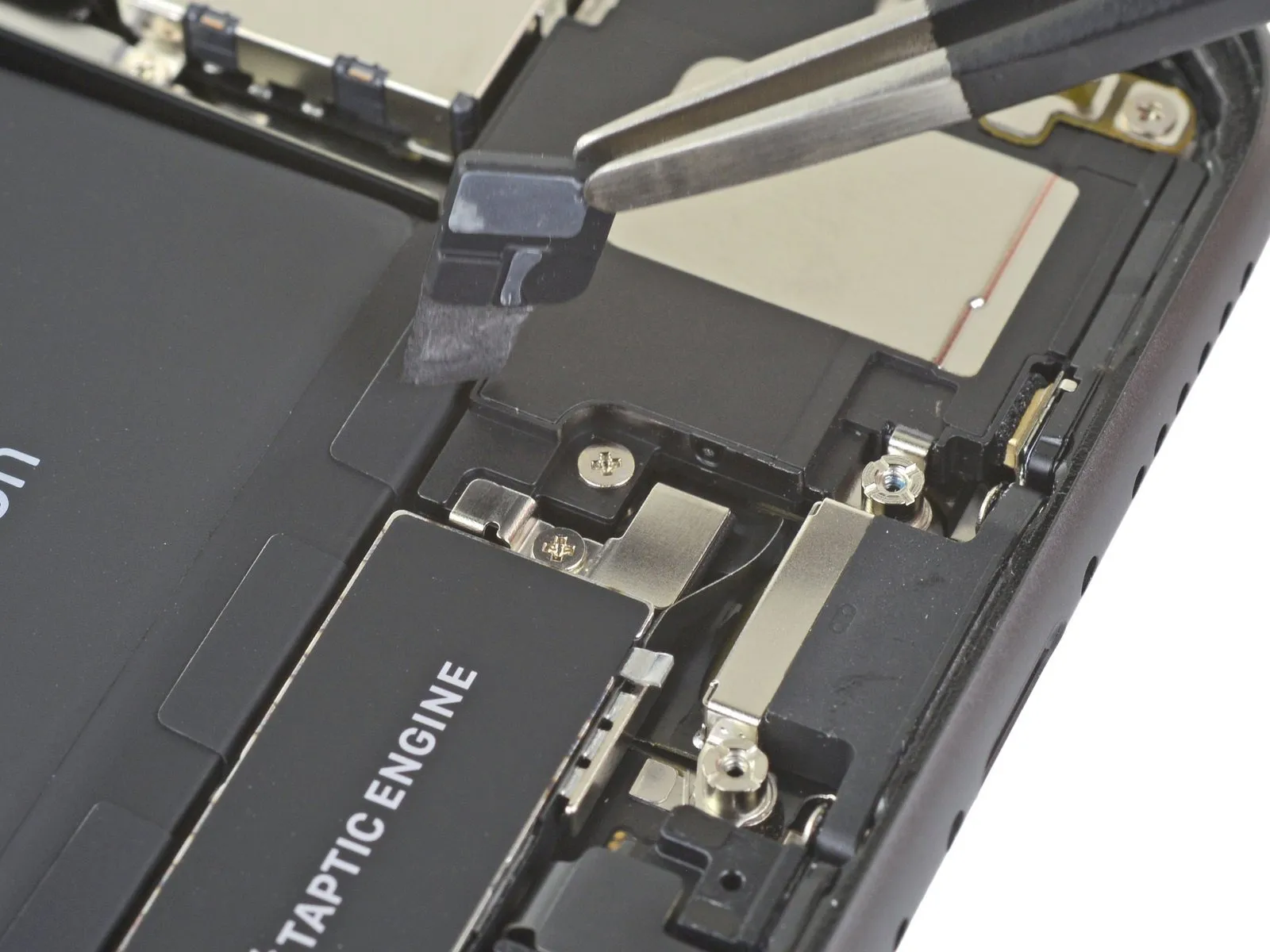
Employ tweezers to carefully detach the black tape and the accompanying rubber pad that shield the Taptic Engine connector.
Applying gentle warmth via a hair dryer or iOpener can facilitate the peeling process of the tape, allowing for subsequent reattachment.
Step 29 | Unscrew the lower speaker
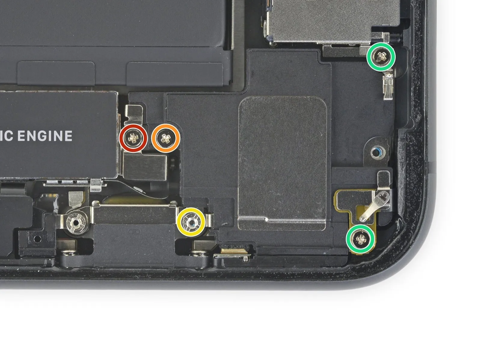
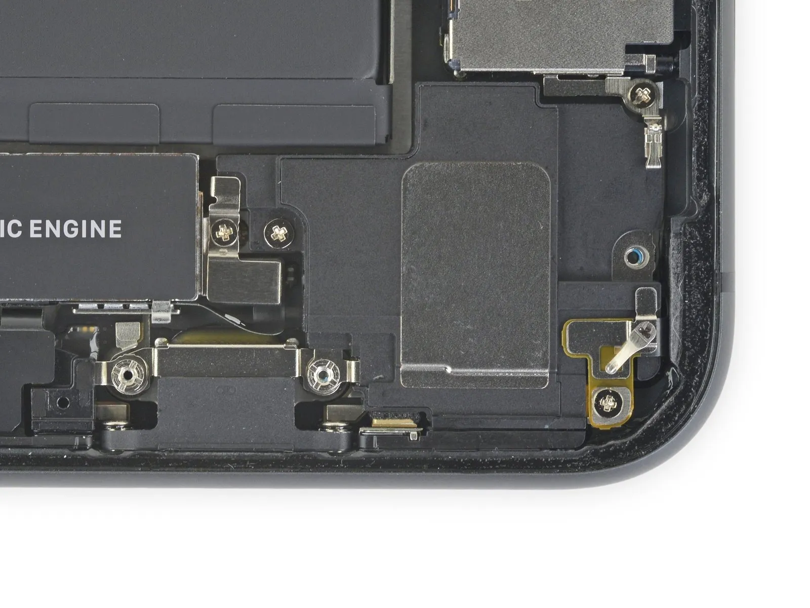
- To detach the speaker and associated mounting hardware, it is necessary to eliminate the five fasteners that hold them in place.
- A Phillips head screwdriver of 1.9 millimeters is required for one specific screw.
- For another screw, a Phillips head screwdriver with a 2.3-millimeter bit is needed.
- A standoff screw, demanding a Phillips head screwdriver of 3.1 millimeters, must also be removed.
- Two screws, each requiring a 1.6-millimeter Phillips head screwdriver, are also part of the disassembly process.
Step 30 | Remove the grounding clip
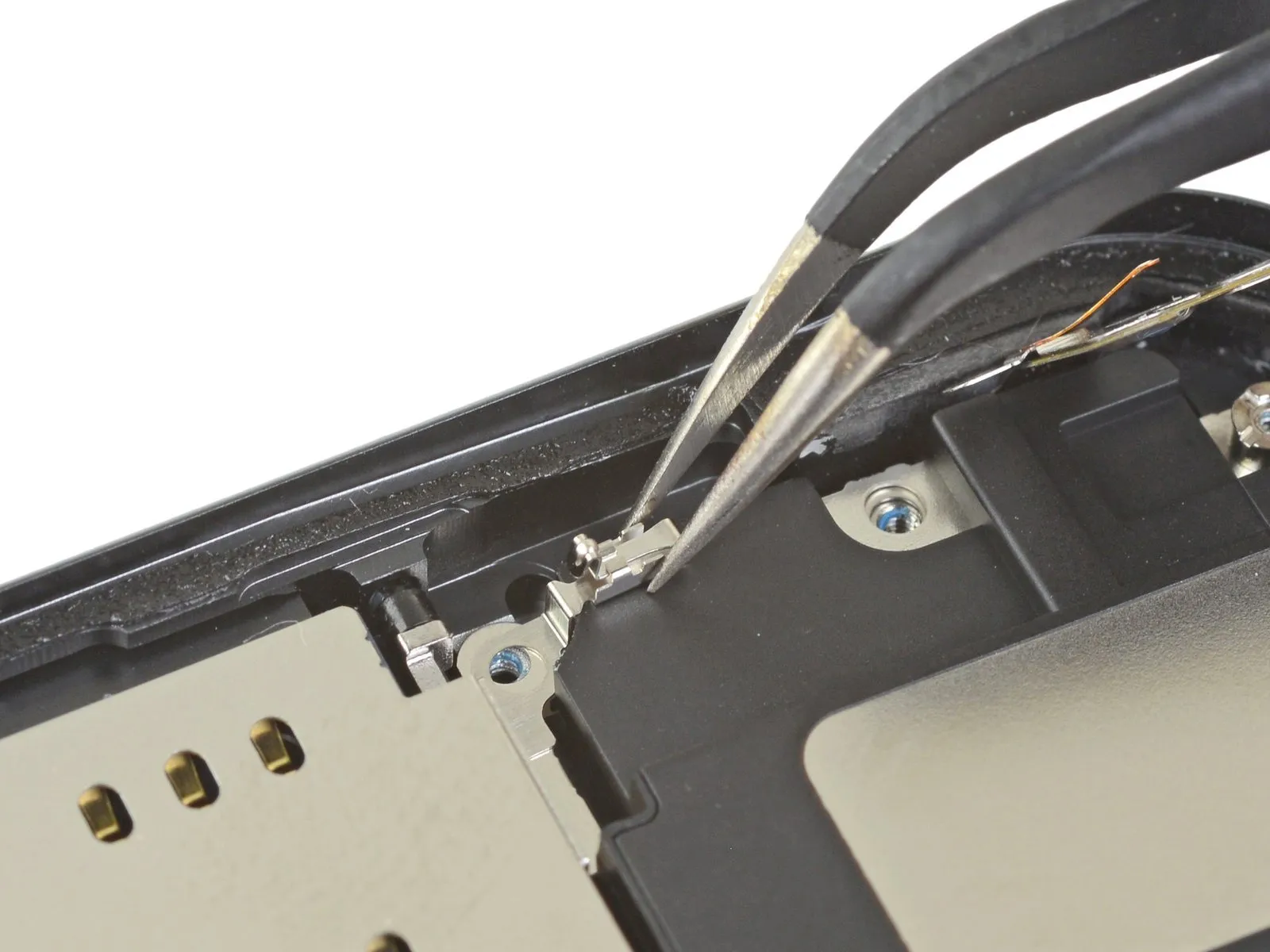
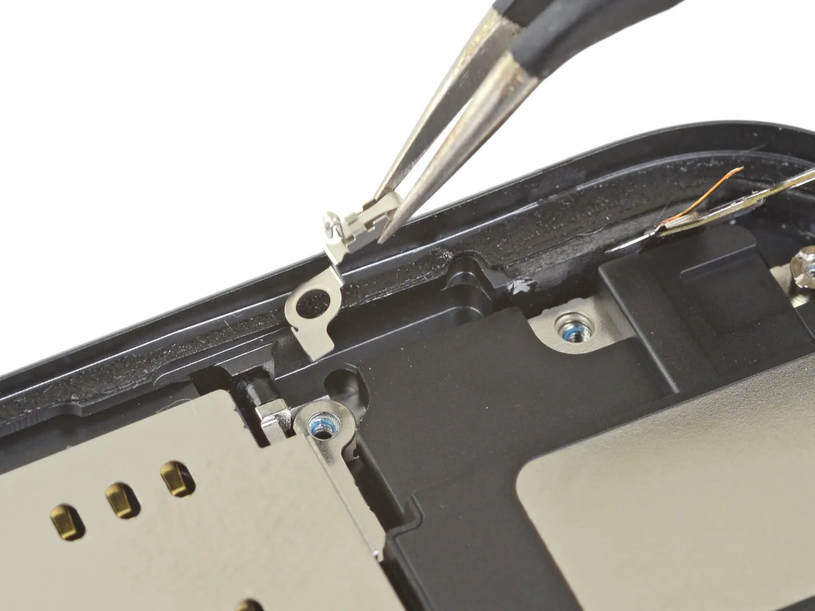
Detach the minor electrical grounding connector situated in the upper-right area of the speaker assembly.
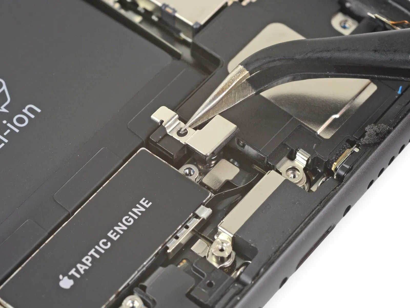
Step 31 | Remove the Taptic Engine connector cover
Step 32 | Remove the speaker standoff screw
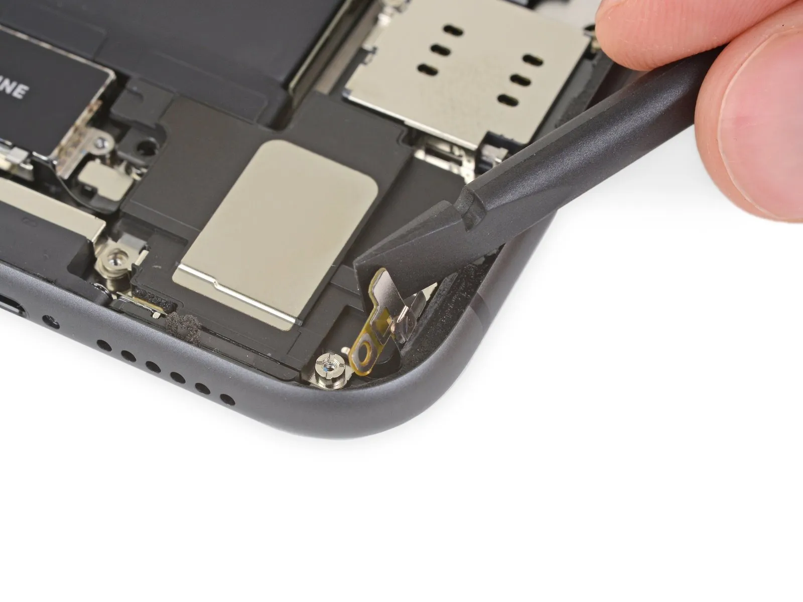
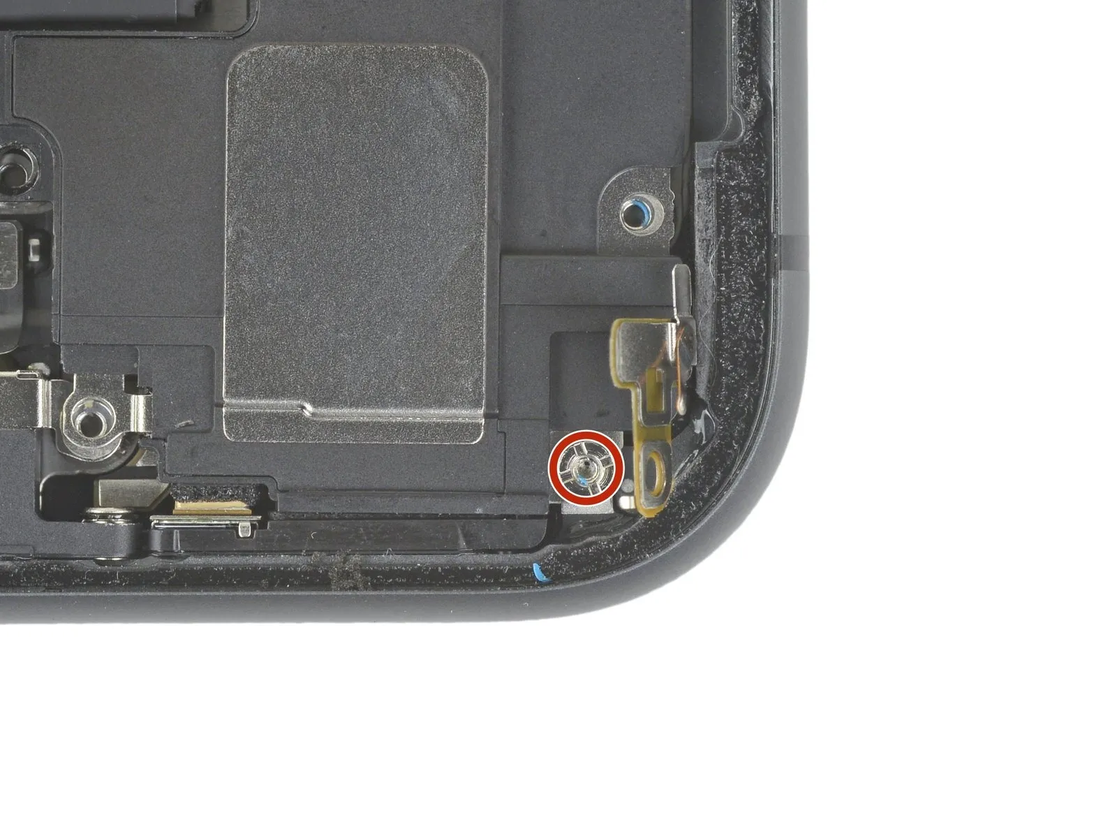
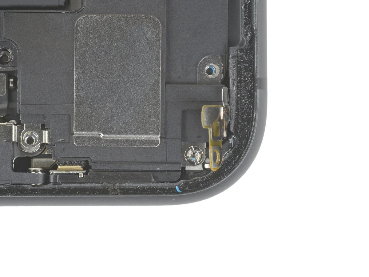
- To access the final speaker fastener, carefully elevate and displace the diminutive board situated in the lower-right corner of the iPhone’s enclosure.
The subsequent step involves extracting a2.4 mm standoff screwlocated directly beneath the displaced board.
Step 33 | Loosen the speaker
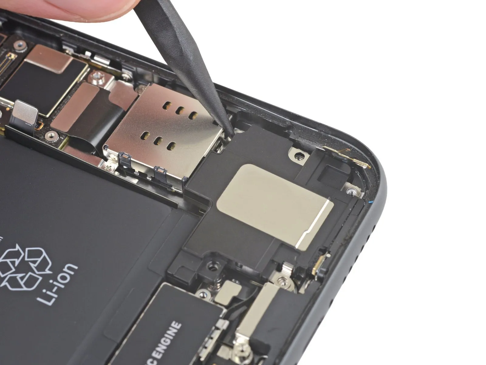
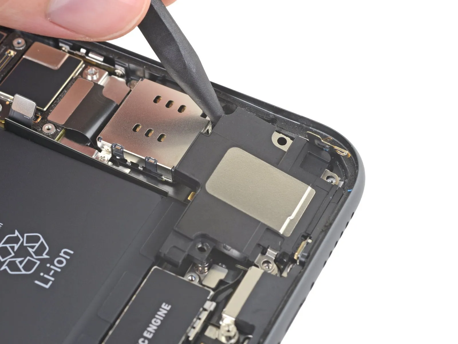
- Employ a spudger to gain access beneath the speaker's upper boundary, positioned close to the iPhone enclosure's perimeter.Carefully leverage the spudger to elevate the speaker's top edge, applying gentle upward force.The lifting action should be focused on separating the speaker from the iPhone's casing.
- This maneuver facilitates disengagement of the speaker assembly from its mounting location.
Step 34
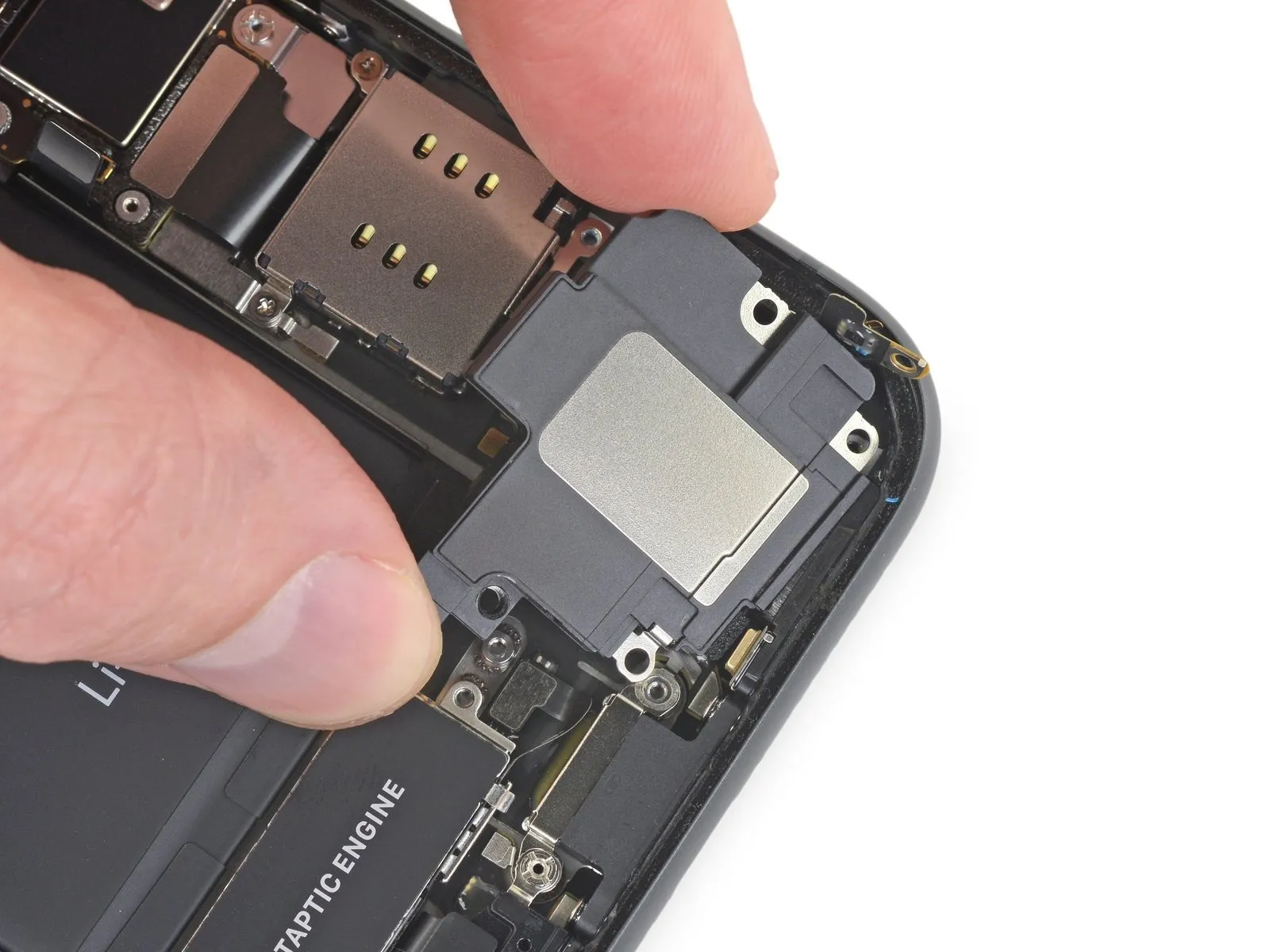

- Grasp the speaker assembly using its lateral edges, gently oscillating it to disengage the adhesive that bonds it to the iPhone's lower perimeter.
- Continue moving the speaker outward from the iPhone's base until the adhesive gasket releases its seal.
Step 35 | Remove the speaker
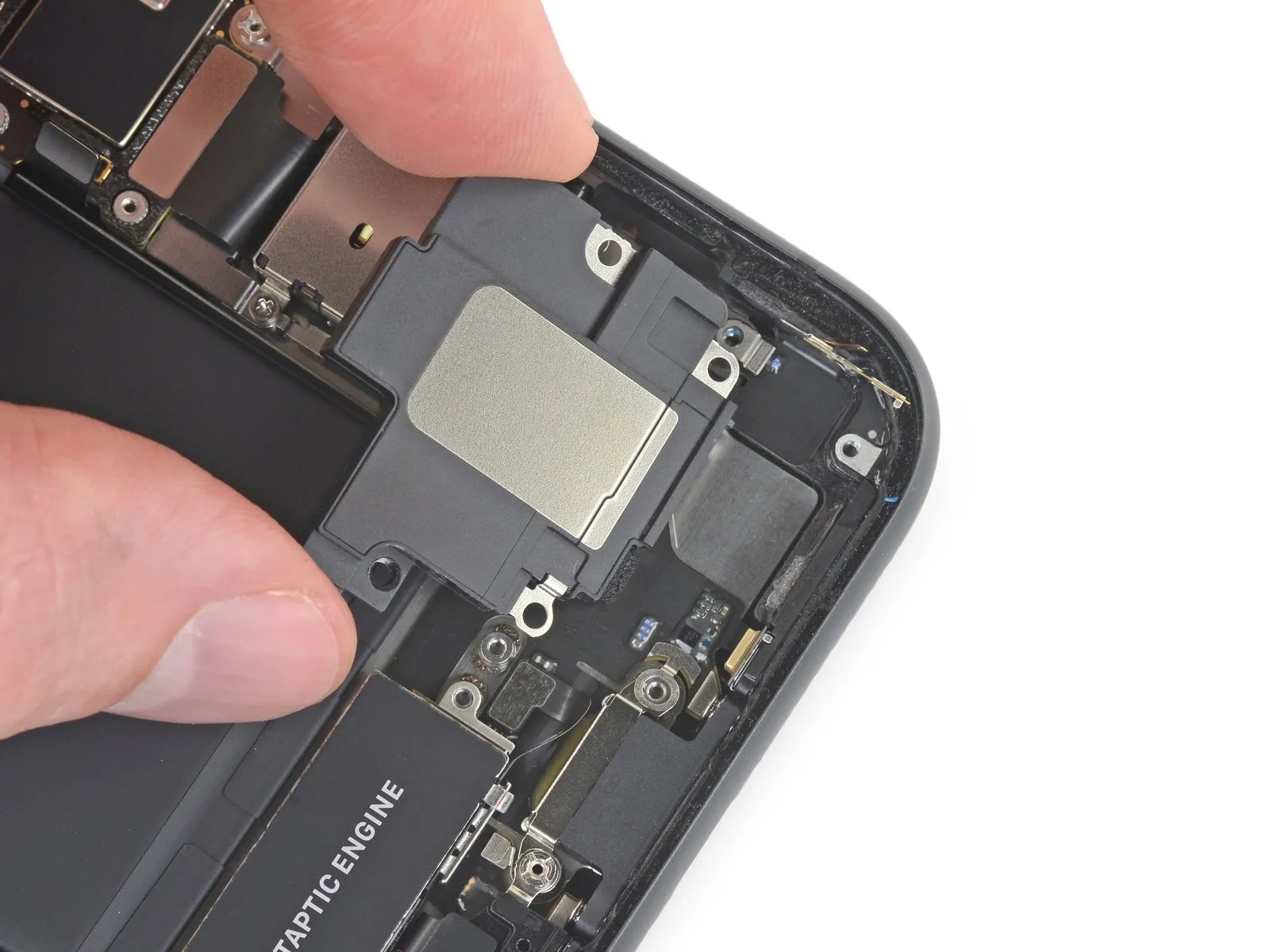
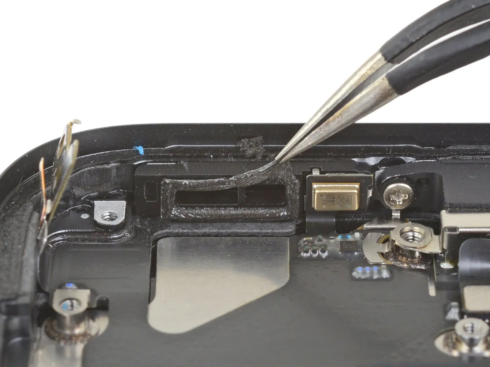
- Detach the speaker component from the device.
- To mitigate potential ingress of moisture and particulate matter, consider substituting the speaker's sealing gasket during reassembly, if desired.
- Residual adhesive traces can be carefully removed using tweezers.Employing tweezers facilitates the removal of any leftover adhesive residue.Ensure proper adhesion of the gasket by cleaning the underlying surface with a small amount of isopropyl alcohol, utilizing a lint-free cloth or a coffee filter.
- A fresh gasket should be applied to the speaker's surface.
- The new gasket must be positioned correctly on the speaker.Following gasket installation, reattach the speaker to the device.Properly securing the speaker is essential for maintaining device integrity.