iPhone 11 Pro Front Camera Replacement Without Losing Face ID
A faulty or broken front-facing camera can be replaced as a discrete component, though the procedure presents significant challenges.The front camera is integrated within a larger unit that incorporates the infrared camera and dot projector.To maintain Face ID capabilities, isolating the front camera for replacement is essential.Replacing solely the front camera preserves Face ID operation; conversely, substituting the entire front camera assembly will disable Face ID.A preliminary test of a replacement camera, while connected, is recommended to confirm the repair's effectiveness.
Successful isolation of the front camera for repair requires careful disassembly and reassembly of the combined module.
The complexity of this repair stems from the tightly integrated nature of the front camera, infrared camera, and dot projector within the assembly.
Step 1 | Remove the pentalobe screws
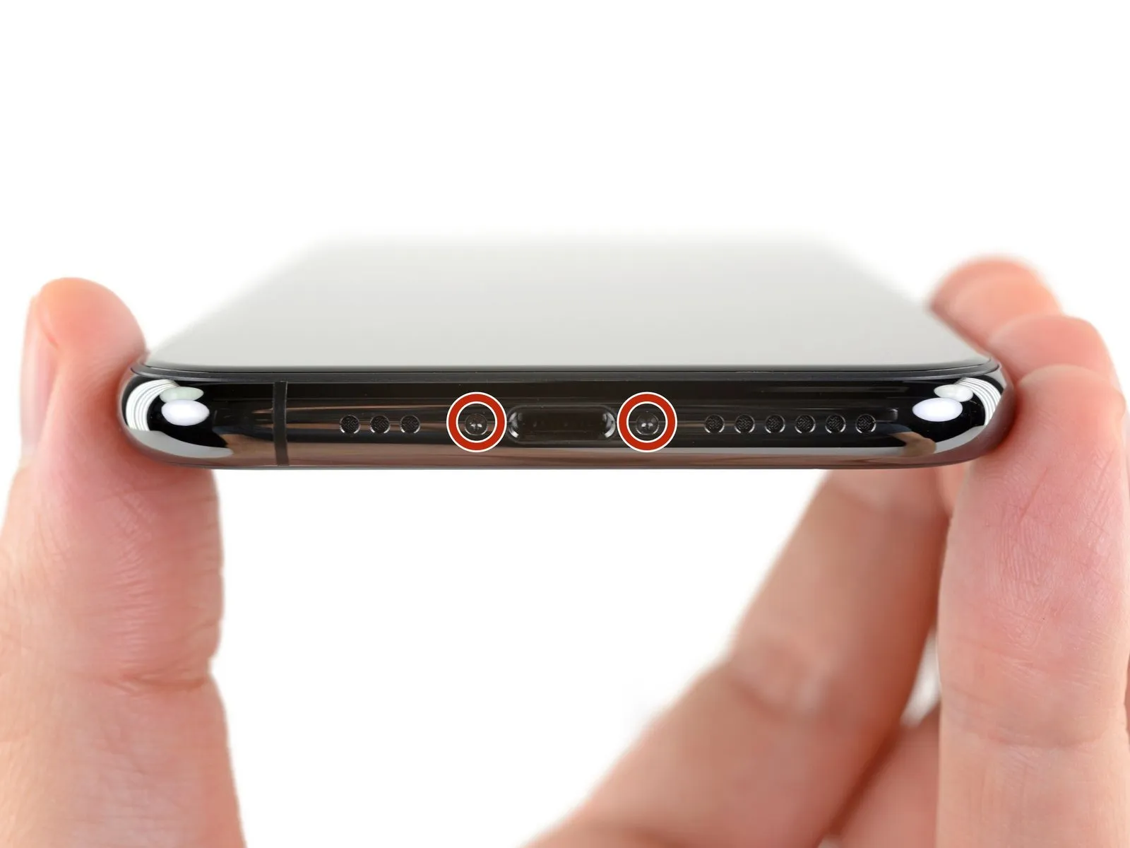
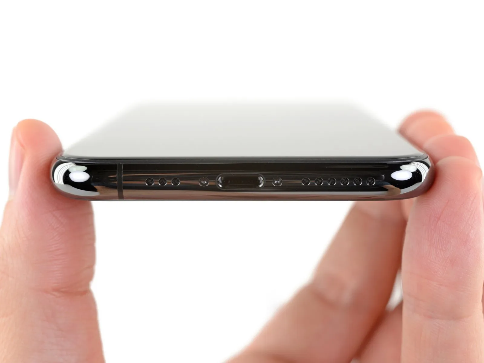
- To ensure safety prior to commencing the repair, allow the iPhone's battery to deplete to a level below 25% capacity.A fully charged lithium-ion battery presents a fire hazard and potential explosion risk if it sustains accidental physical damage.Deactivate the iPhone's power supply before commencing the disassembly process.
- The two screws securing the bottom edge, each measuring 6.7 mm in length and utilizing a pentalobe head, must be removed.
- Separating the iPhone's display assembly will irreversibly damage the integrated waterproof barriers.
- To prevent water ingress, either acquire and install replacement waterproof seals before proceeding beyond display separation, or exercise extreme caution to prevent liquid contact during reassembly if seals are not replaced.
Step 2 | Tape over any cracks


- To mitigate additional damage and potential injury when addressing a cracked iPhone display, secure the fractured glass with adhesive tape.
- Apply successive layers of transparent packing tape across the iPhone's screen surface, ensuring complete coverage of the display's front.
- Protect your vision by utilizing safety eyewear to guard against potential glass fragments that may dislodge during the repair process.
- Should the suction cup fail to adhere properly during subsequent procedures, create a handle from a durable tape, like duct tape, to facilitate screen lifting.
- As a last resort, secure the suction cup to the screen's surface using superglue to maintain a firm grip.
Step 3 | Anti-Clamp instructions


The subsequent three procedures illustrate the function of the Anti-Clamp, a specialized tool developed to simplify the initial separation process; if this tool is unavailable, proceed to the alternative instructions located three steps further down.
Detailed operational guidance for the Anti-Clamp is accessible through a separate instructional document.
- To release the Anti-Clamp's gripping arms, retract the blue handle towards the rear.
- Carefully position the arms across either the left or right side of the iPhone's frame.
- Place the suction cups adjacent to the lower edge of the iPhone, ensuring one is situated on the front surface and the other on the rear.
- Apply pressure by compressing the cups together to establish a secure vacuum seal on the intended area.
- Should the iPhone's surface exhibit excessive slipperiness, hindering the Anti-Clamp's ability to maintain adhesion, applying adhesive tape can enhance grip.
Step 4


- Advance the blue handle to secure the arm assemblies in their engaged position.
- Rotate the handle a full 360-degree circle, or continue turning until the vacuum cups begin to deform.
- Maintain precise alignment between the suction cups; should displacement occur, slightly release the cups' hold and reposition the arms.
Step 5


- Employing an iOpener, introduce it between the Anti-Clamp’s arms by threading it through.Alternative heating methods, such as hair dryers, heat guns, or hot plates, are permissible; however, exercise caution to prevent damage to the display or internal battery due to excessive temperatures.Position the iOpener to rest along the lower edge of the iPhone’s frame by folding it appropriately.Allow a sixty-second interval to facilitate adhesive separation and the creation of a discernible opening.Introduce an opening pick into the space formed beneath the screen and the plastic bezel, ensuring it does not contact the display surface.
- If the Anti-Clamp fails to generate an adequate separation, increase the heat applied to the area.
- Rotate the Anti-Clamp’s handle incrementally, no more than ninety degrees at a time.Between each rotational adjustment, pause for sixty seconds to allow the adhesive to weaken further.Rely on the Anti-Clamp’s pressure and the passage of time to achieve separation, avoiding forceful manipulation.
- The iOpener’s heat assists in softening the adhesive securing the display.
- A heat source is crucial for weakening the adhesive bonds.
- The Anti-Clamp’s design allows for a controlled separation force.Observe the adhesive’s response to heat by monitoring the gap’s size.Incremental rotations of the Anti-Clamp prevent excessive force application.
- The opening pick is inserted to maintain the separation achieved by the heat and Anti-Clamp.Adhesive release is a gradual process requiring patience and controlled heat.Maintain a cautious approach to avoid damaging the iPhone's components.
Step 6 | Heat the lower edge of the phone
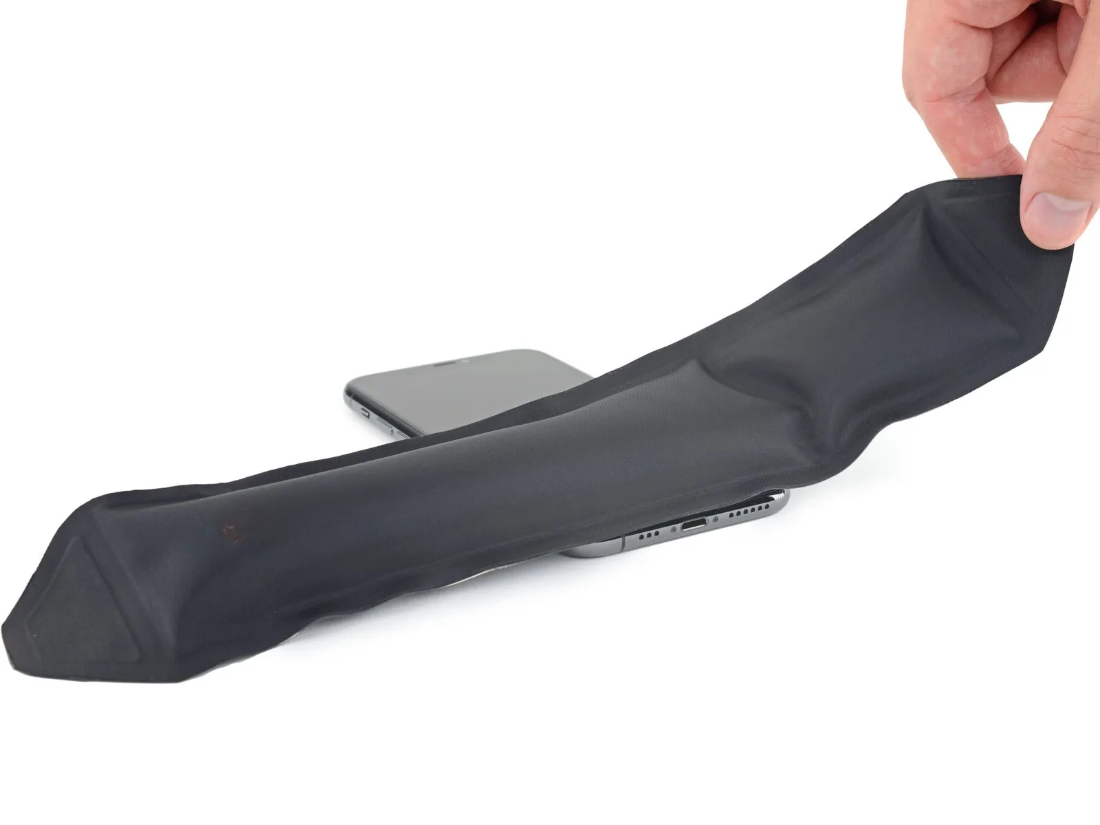
Applying warmth to the iPhone's bottom edge facilitates separation by reducing the adhesive's hold on the display assembly.
Employing a hairdryer, heat gun, or an iOpener can provide the necessary heat source.An iOpener is a suitable tool for this process.Warm the lower edge of the iPhone's display for approximately one minute to reduce the adhesive's bonding strength.
Step 7
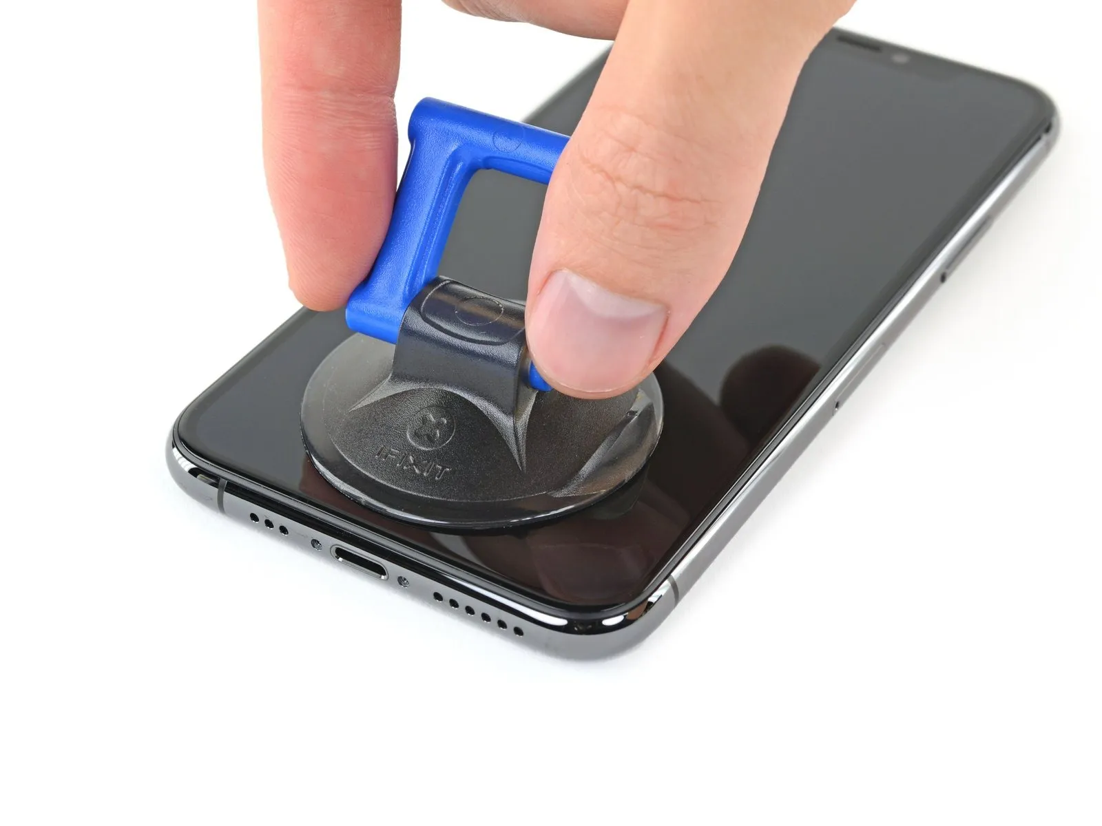
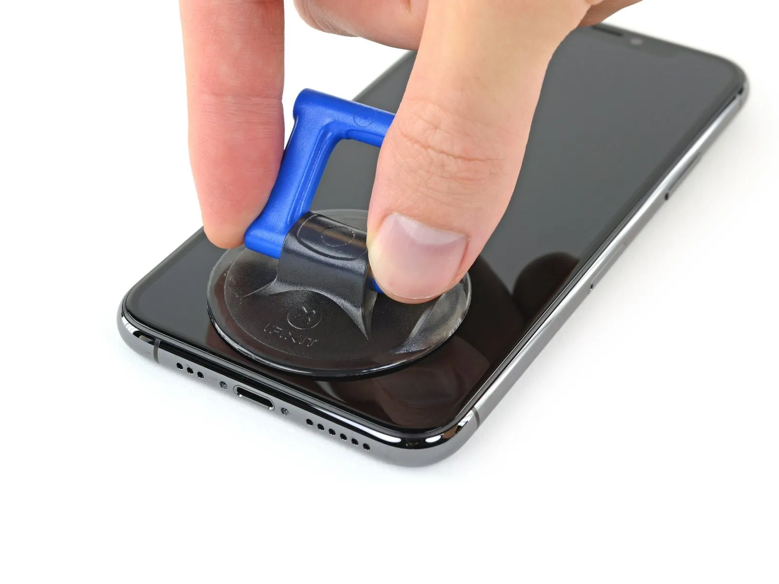
When employing a solitary suction handle, position it against the lower perimeter of the device's frame, ensuring it does not contact the rounded section of the glass covering.
Step 8 | Lift the display slightly
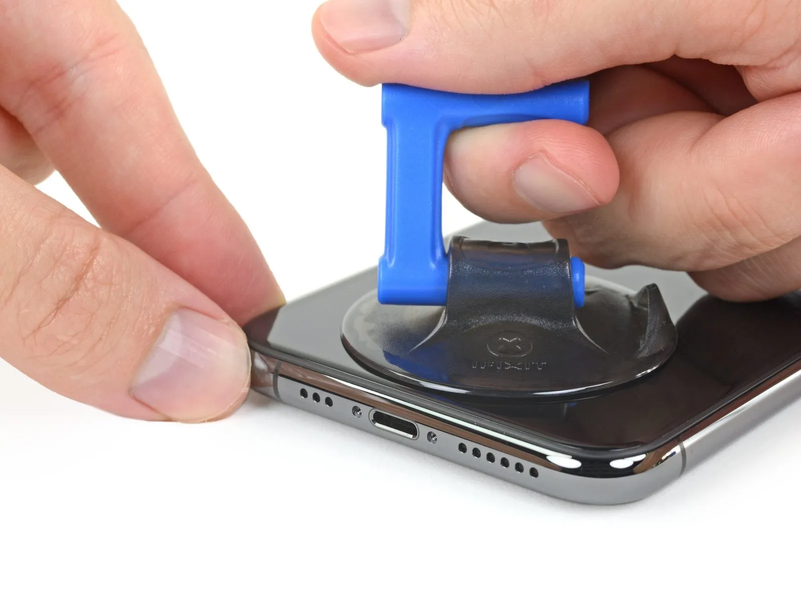
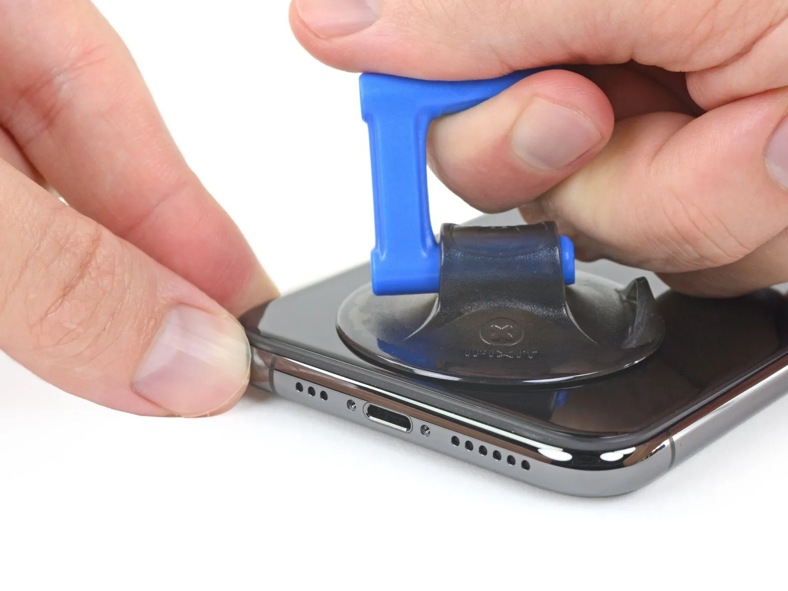
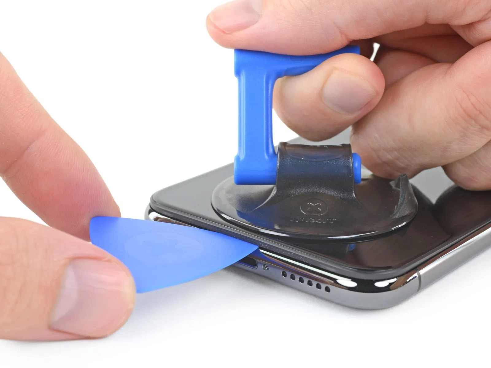
- Apply steady, consistent upward force to the suction cup to generate a small separation between the device's front panel and its rear casing.
- Carefully slide an opening tool into the space formed beneath the display screen and the surrounding plastic frame, ensuring it does not contact the screen's surface.
- Due to the robust nature of the waterproof sealant securing the display, a considerable amount of force may be necessary to initially create this separation; if encountering difficulty, applying additional heat and gently oscillating the screen can help to loosen the adhesive, facilitating tool insertion.
Step 9 | Separate the screen adhesive
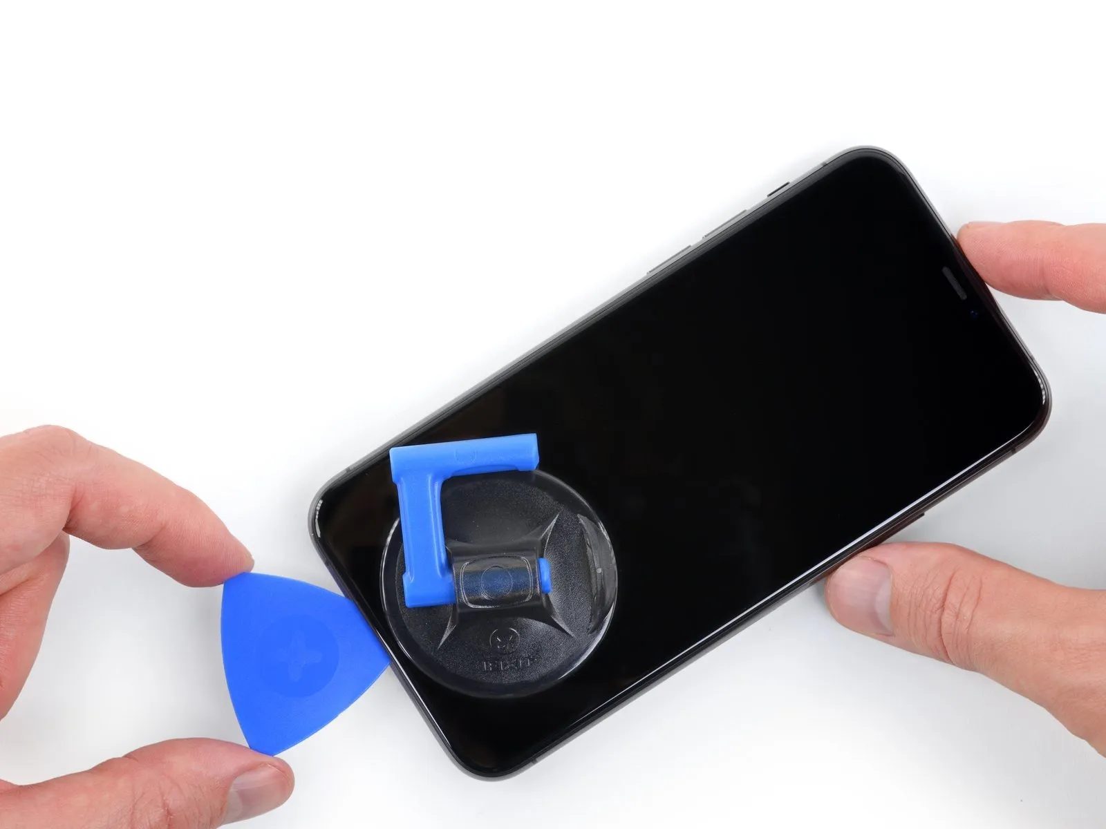
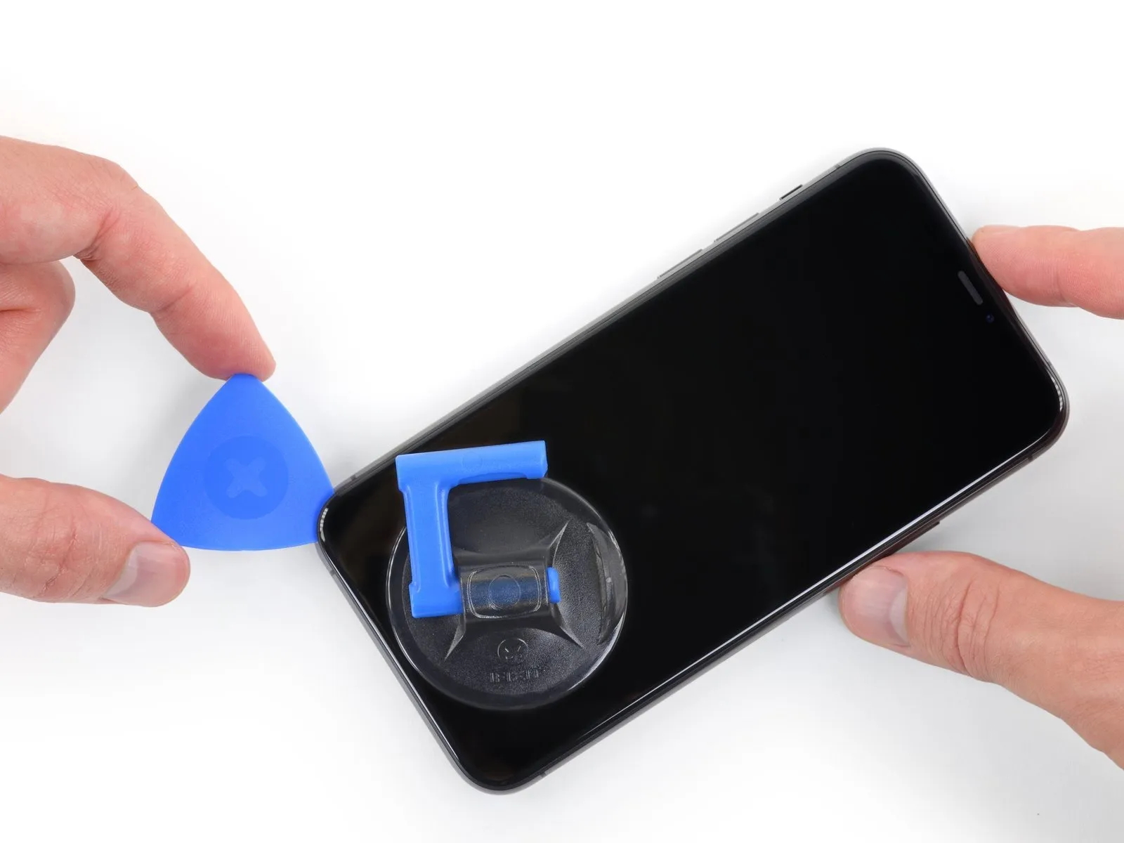
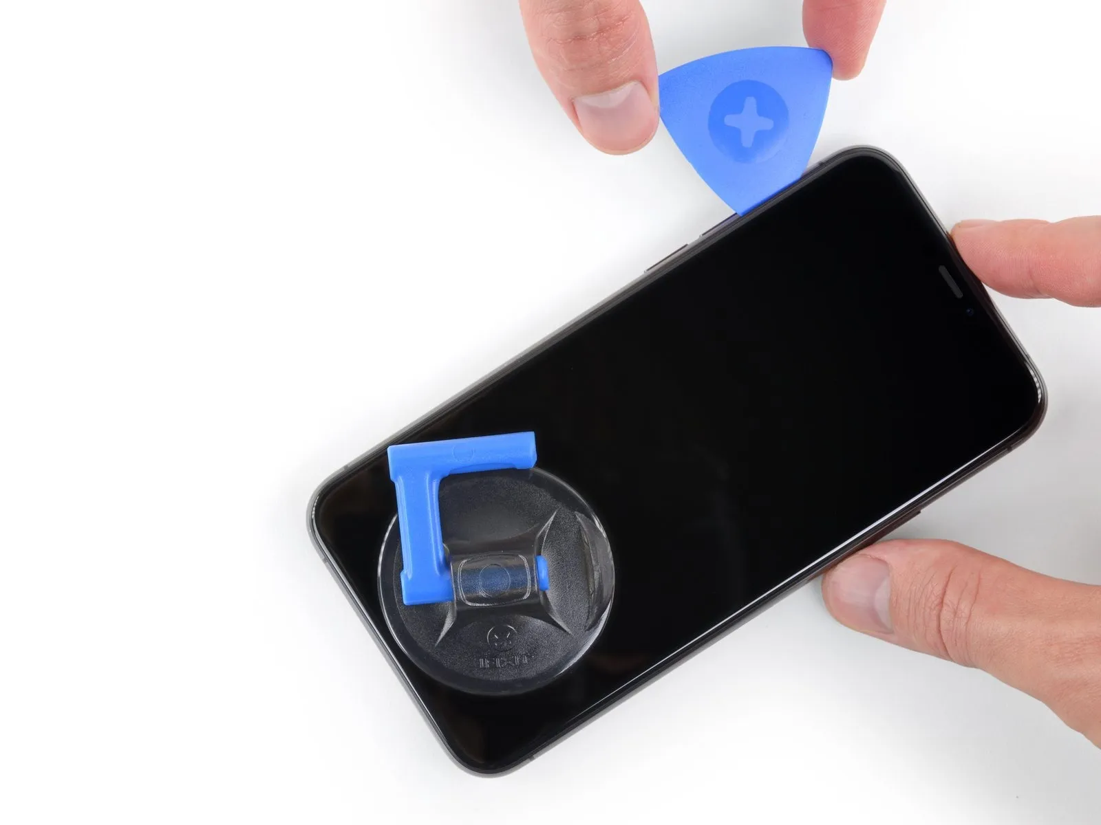
- To release the adhesive securing the display assembly, maneuver a specialized opening tool along the lower-left perimeter and upward along the left side of the iPhone’s casing.
- Ensure the pick’s insertion depth remains limited to a maximum of 3 millimeters to prevent potential harm to delicate internal parts.Excessive pick insertion beyond this specified depth carries a risk of component damage.Carefully manage the opening tool to avoid compromising the integrity of the iPhone’s internal components.
Step 10 | Screen information

A fragile cable resides along the iPhone's right side; avoid inserting any tools in this area to prevent potential cable damage.
Step 11

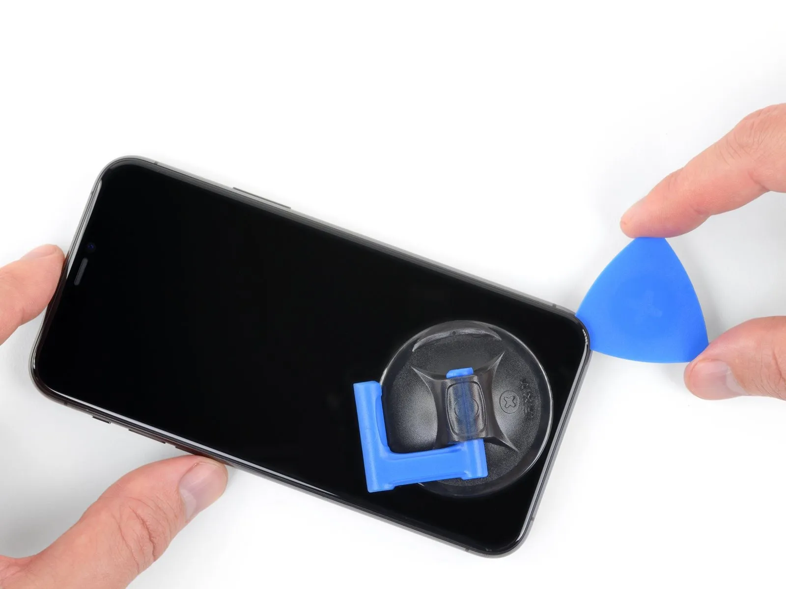
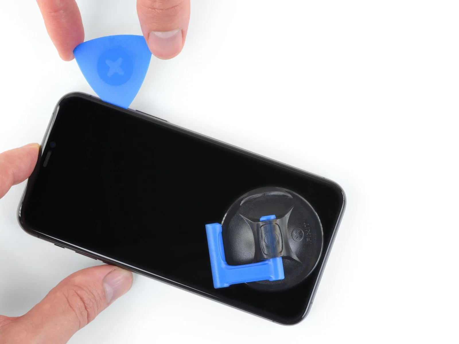
- To proceed with separating the adhesive, reposition your opening tool at the lower edge of the iPhone's frame and advance it upwards along the right side.
- Ensure the opening tool's insertion depth remains limited to a maximum of 3 millimeters to prevent potential harm to the delicate display cable connections.Exceeding this 3-millimeter depth poses a risk of damaging the internal display cabling.Carefully manage the tool's position to avoid exceeding the specified 3 mm insertion depth.
Step 12
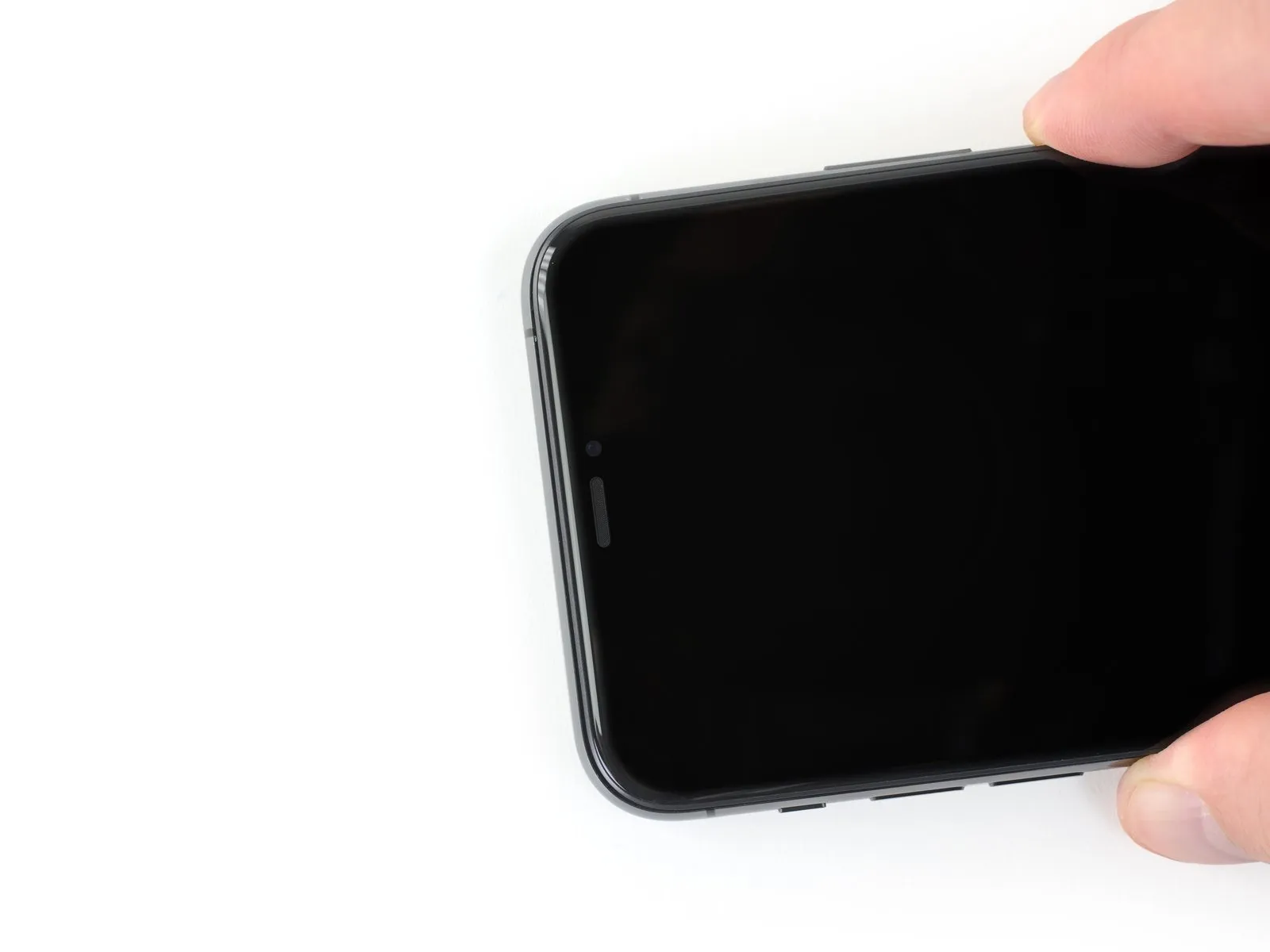
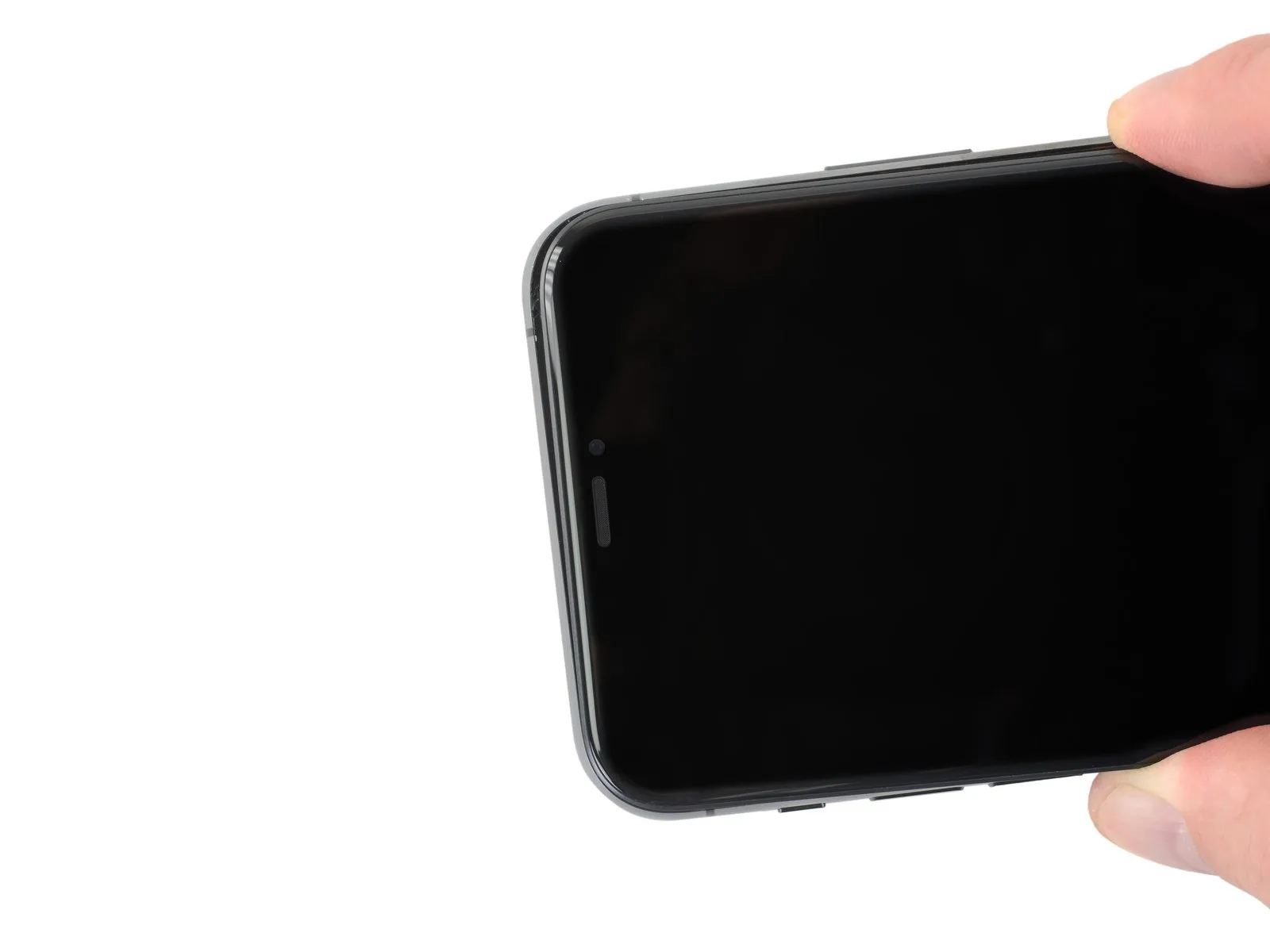
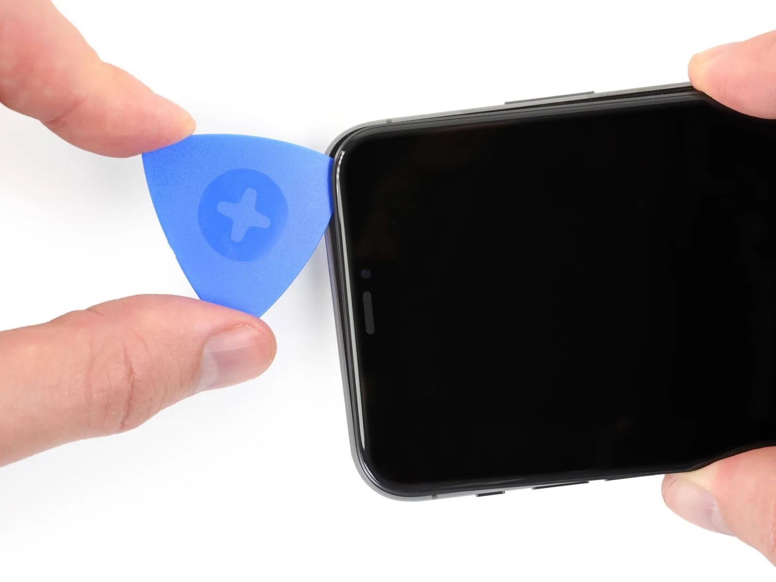
Adhesive and retaining clips together fasten the display's upper boundary.
Exercise caution while applying slight downward tension to the display's right side, oriented towards the Lightning connector.
Position a specialized opening tool within the upper-rightmost section of the device's casing.
Step 13

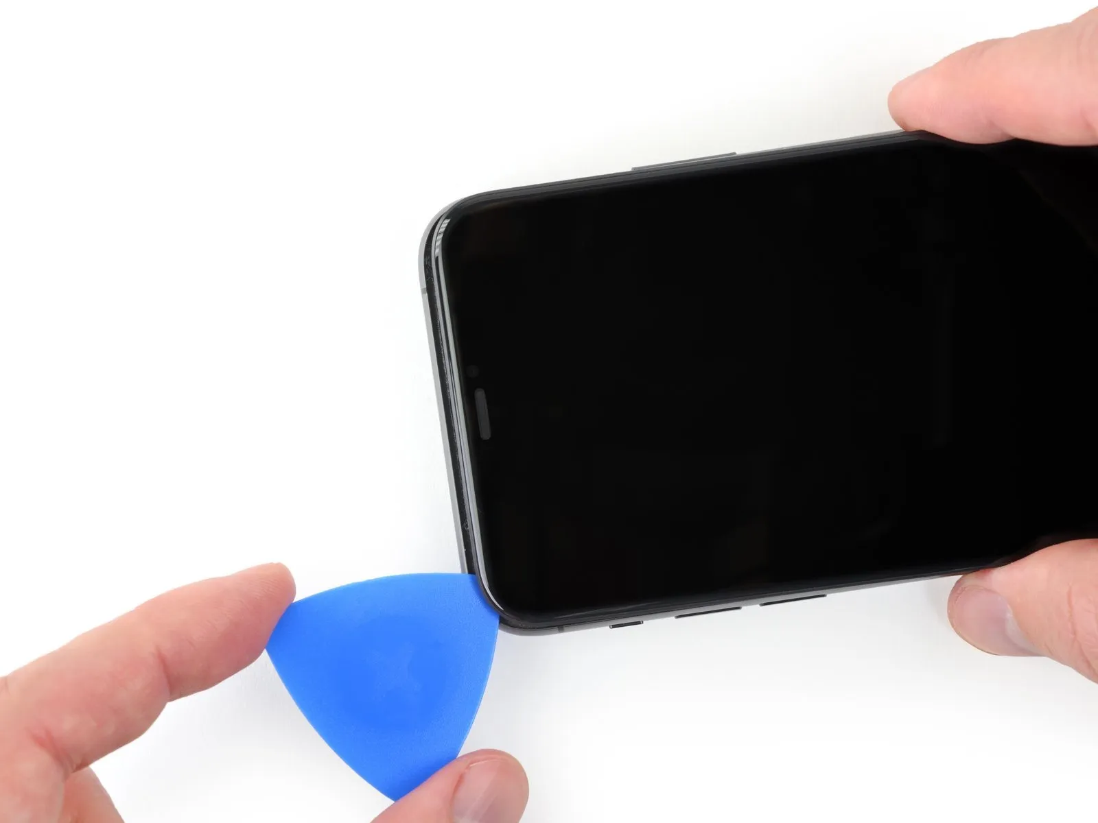
- Maintain downward pressure on the display assembly, directing it towards the Lightning connector, as necessary to create sufficient space for tool insertion.
- Employ the pick to move along the top left edge, severing any residual adhesive bonds holding the display in place.
- Limit pick insertion depth to a maximum of 3 millimeters to prevent potential harm to the front panel sensor array.
Step 14 | Remove the suction cup

To detach the suction cup from the front panel, grasp and exert force on the small protrusion located on its surface.
Step 15 | Open the iPhone
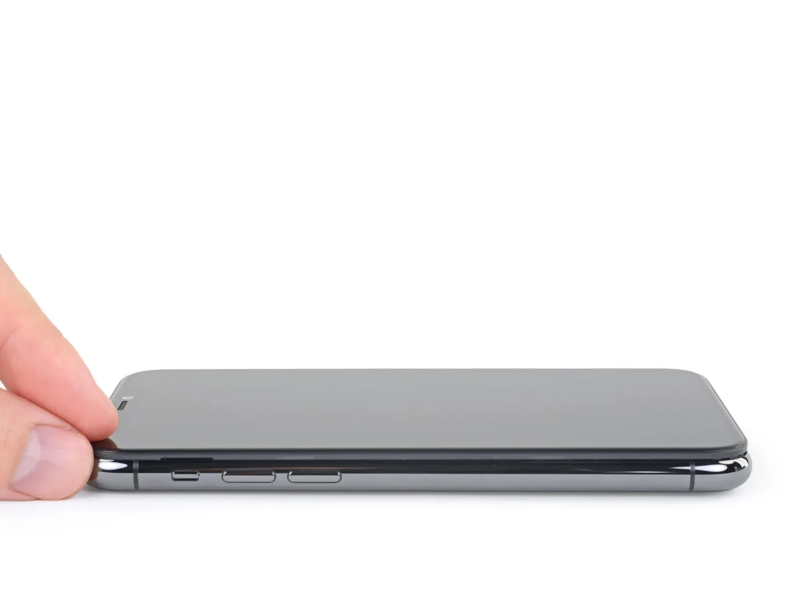
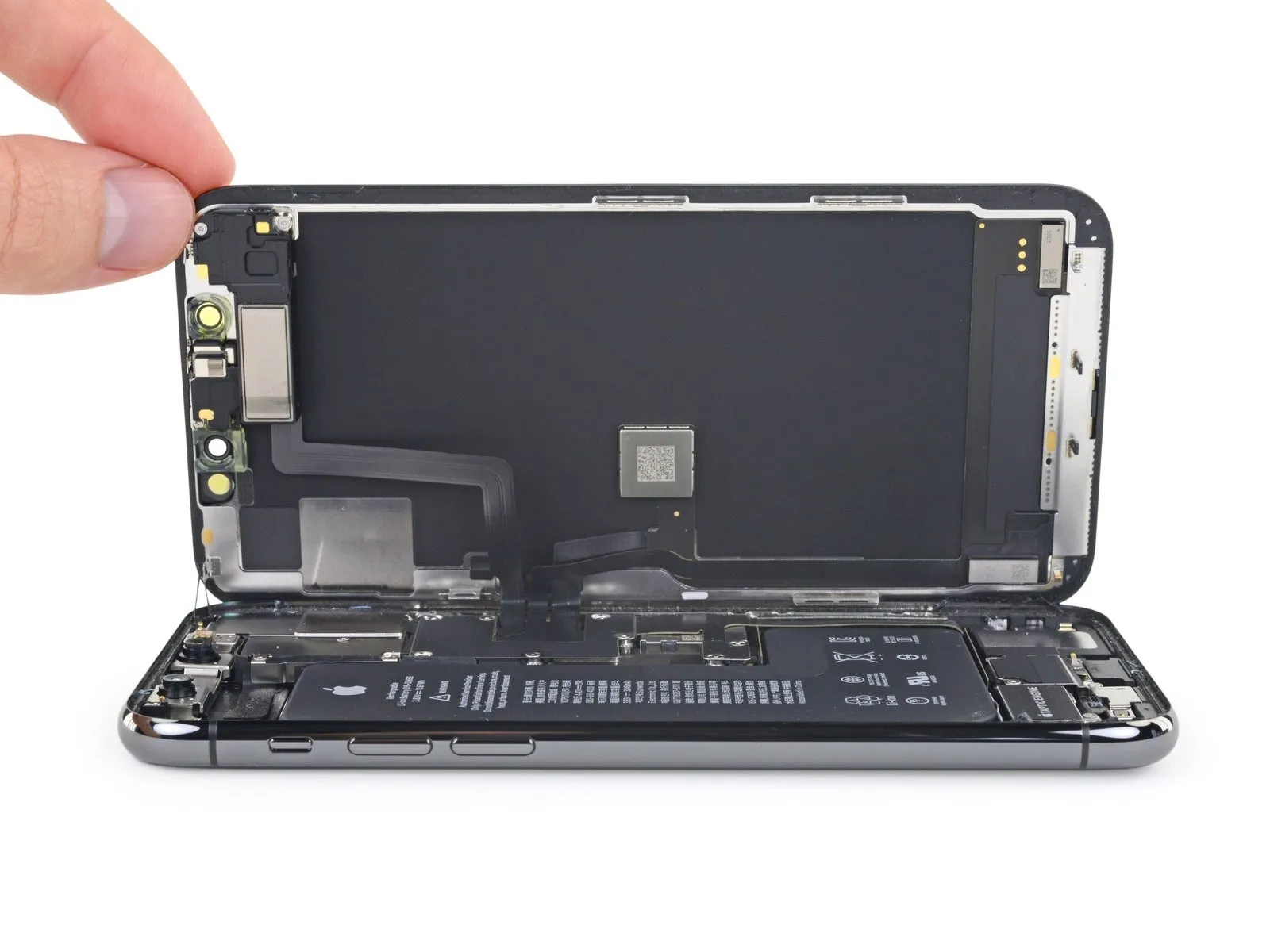
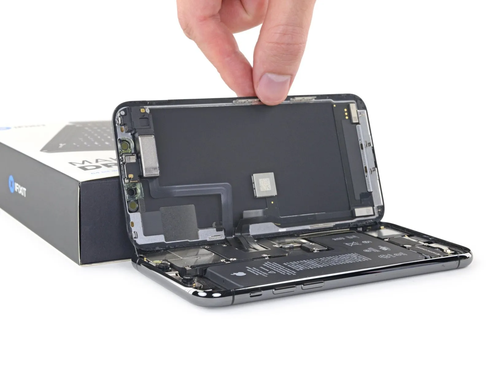
- To access the iPhone's internal components, initiate the opening process by pivoting the display upwards, starting from the left edge, mimicking the action of opening a book's cover.
- Avoid completely disconnecting the display at this stage, because multiple delicate ribbon cables remain attached to the iPhone's logic board.
- Secure the display in an upright position using a support to maintain access to the internal components during the repair.
- When reassembling the device, position the display, ensuring proper alignment of the clips along the upper edge, then apply gentle pressure to the top edge to secure it before fully engaging the remaining portion of the display; if resistance is encountered, inspect the clips around the display's perimeter for any deformation.
Step 16 | Unscrew the battery connector cover
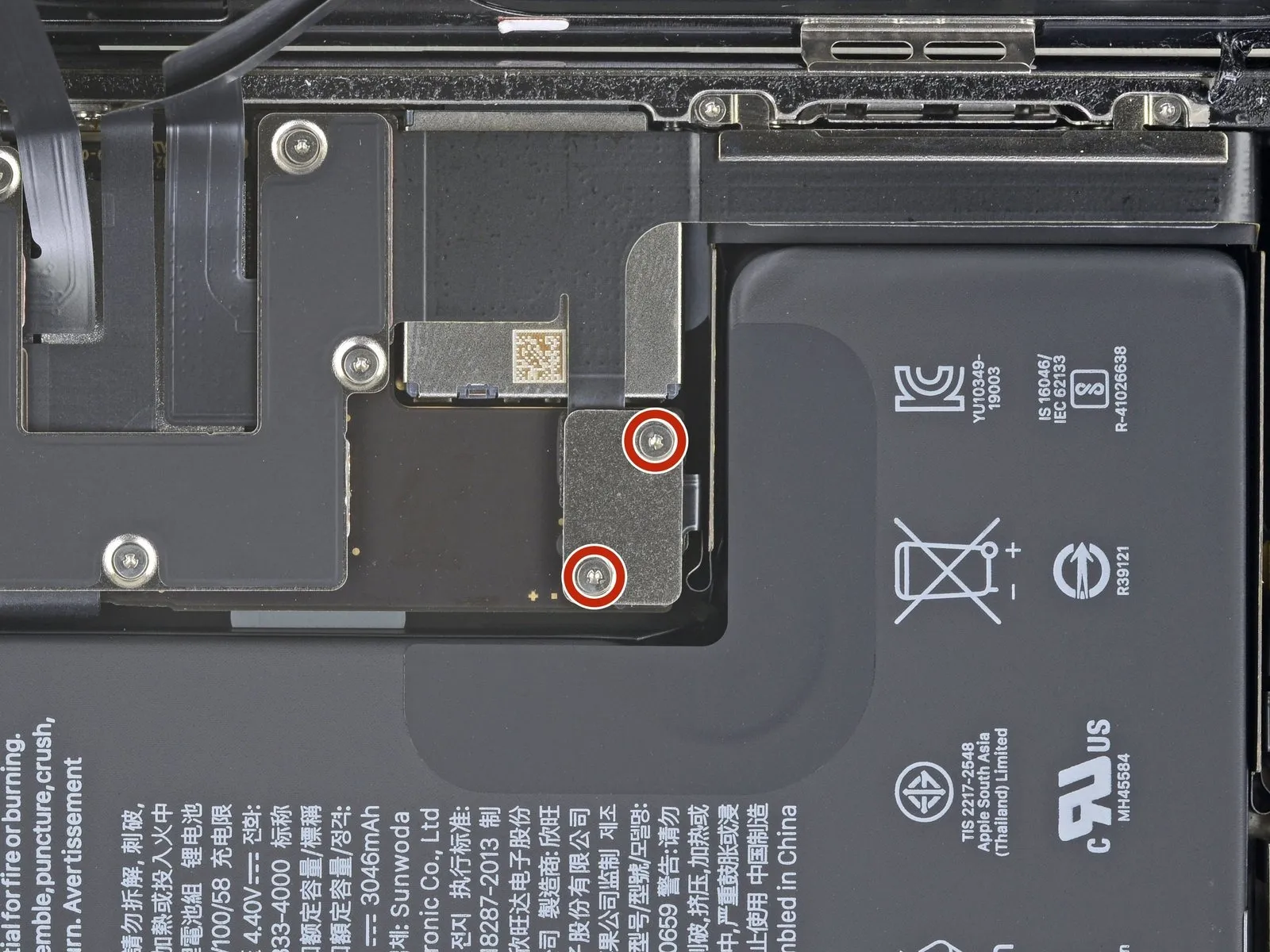
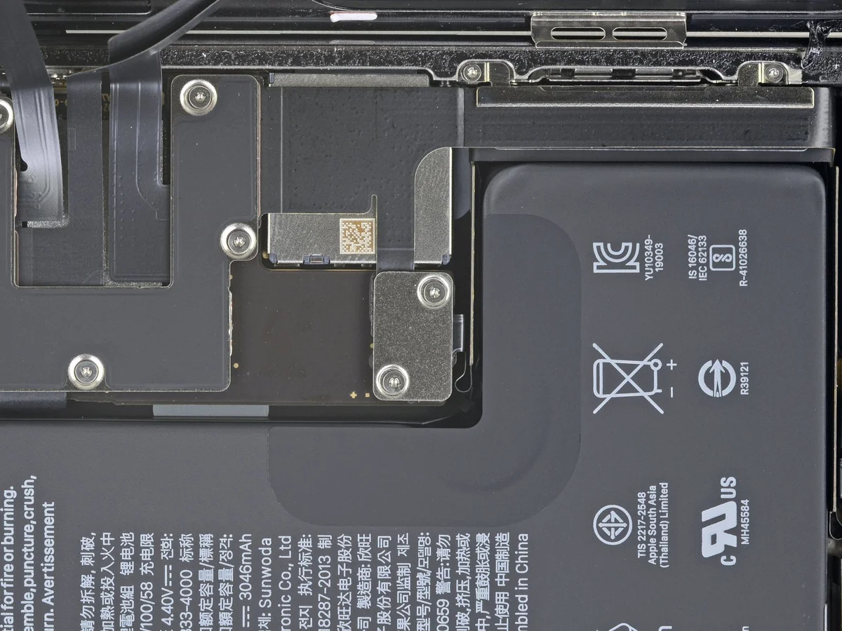
Begin by detaching the battery cover bracket using two Y000 screws, each measuring 1.3 millimeters in length.
- Carefully monitor the location of every screw during disassembly to ensure correct placement during reassembly, preventing potential damage to the iPhone.Accurate screw management is crucial to avoid causing harm to the device's internal components.Prior to final display installation, it's advisable to briefly activate the iPhone to verify full operational status.
- A comprehensive functional test should be performed at this stage to confirm all features are working as intended.
- Completely deactivate the iPhone after testing its functionality to prepare for the subsequent reassembly steps.
Step 17 | Remove the battery connector cover
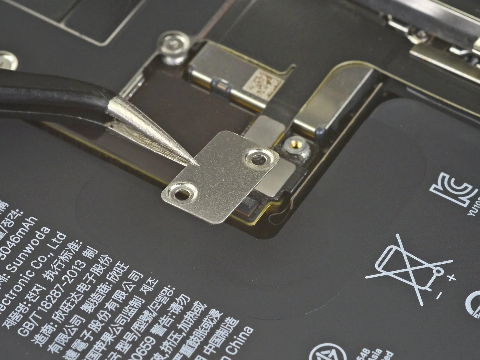
- The bracket must be removed to continue the repair process.
Step 18 | Disconnect the battery
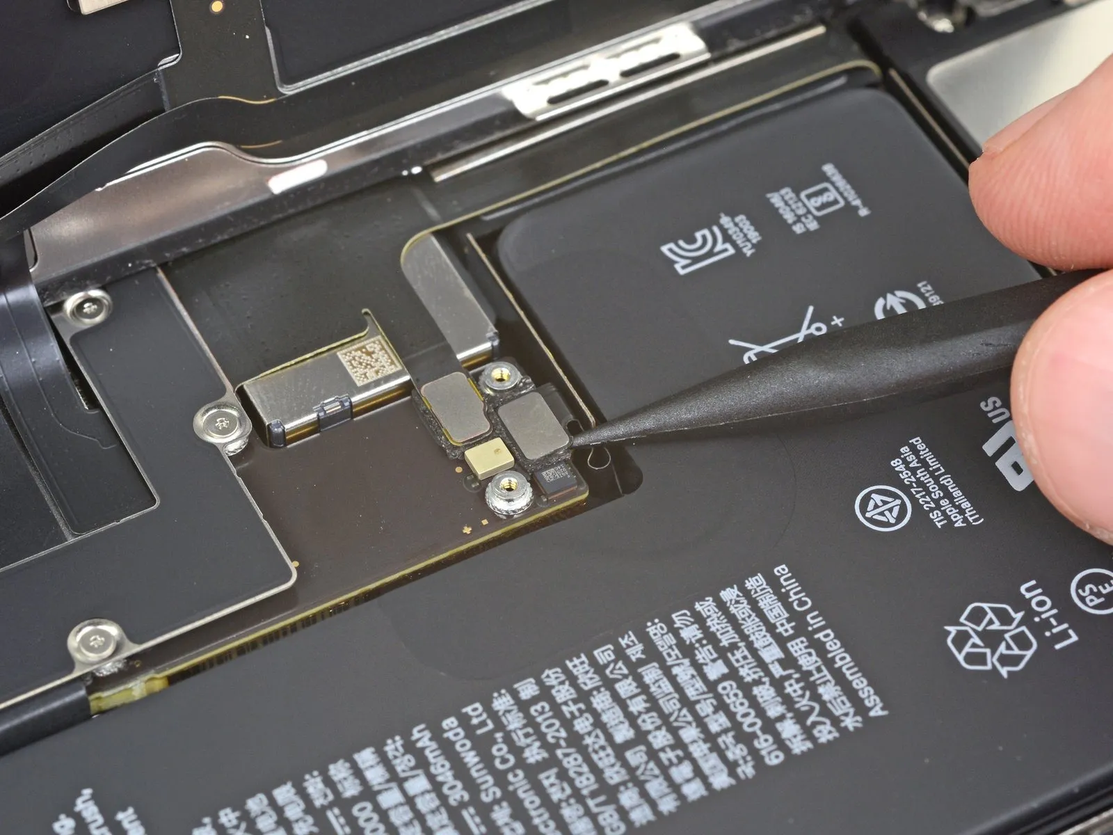
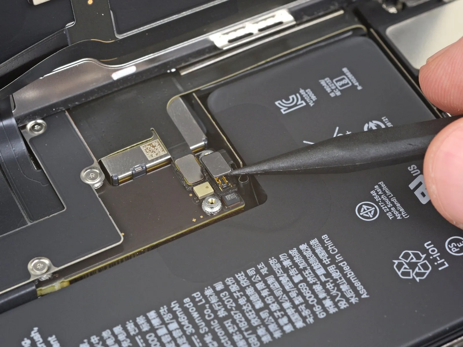
- Carefully lift the battery connector's retaining clip from its corresponding receptacle on the logic board’s surface.Exercise caution to avoid compromising the integrity of the black silicone sealant that surrounds this and other connections on the board.This sealant is crucial, as it offers additional safeguarding against ingress of both water and particulate matter.
- To preclude unintended power delivery to the device during the repair process, gently deflect the connector away from the logic board’s surface.
- This slight repositioning minimizes the risk of accidental contact between the connector and the socket.
Step 19 | Unscrew the logic board cover screws
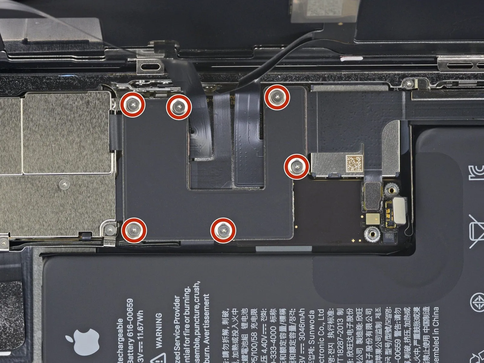
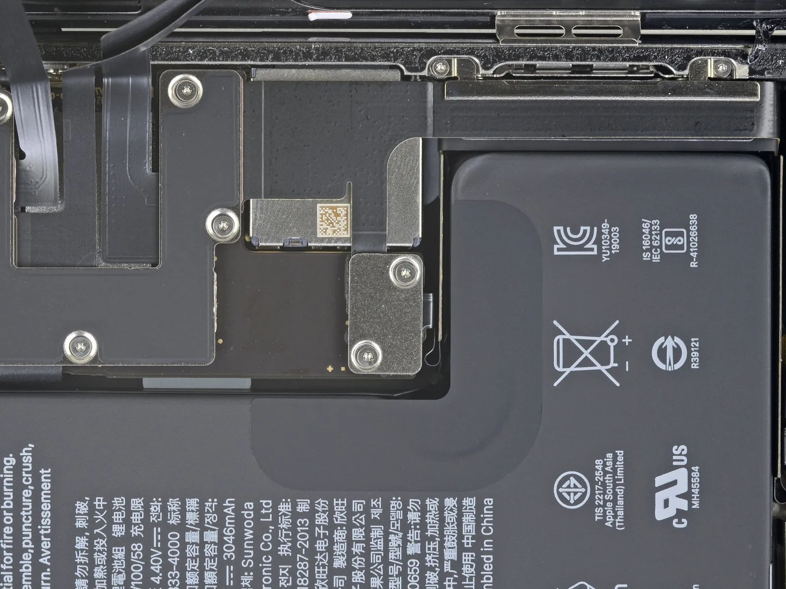
- Six screws, each measuring 1.3 millimeters in diameter, fasten the logic board cover bracket and must be detached.The Y000 driver is the appropriate tool for loosening and removing these fasteners.Carefully unscrew and retain these components for reassembly.
Step 20 | Remove the logic board cover bracket
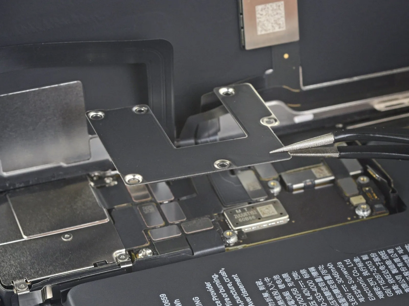
- The bracket must be carefully removed at this stage.
Step 21 | Disconnect the Face ID hardware
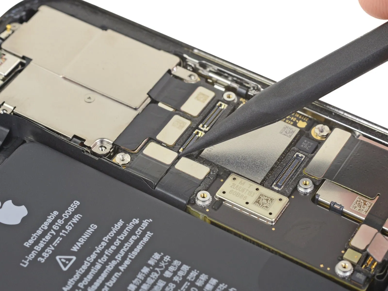
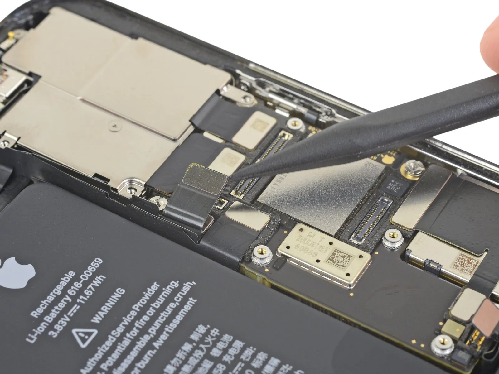
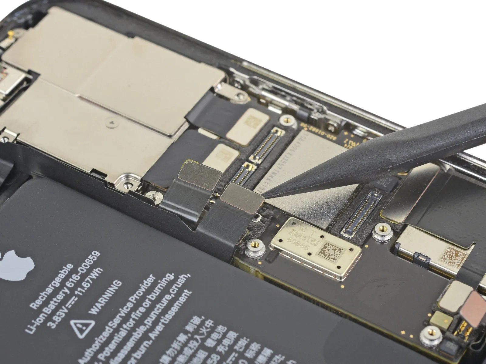
Employing a spudger or fingernail, carefully separate the Face ID dot projector and sensor cable connectors from their corresponding receptacles on the logic board.The Face ID dot projector and sensor cables must be detached from the logic board's sockets using a specialized tool like a spudger, or cautiously with a fingernail.To release the Face ID dot projector and sensor cables, utilize a spudger or fingernail for disconnecting them from the sockets situated on the logic board.A spudger, or a fingernail, should be used to carefully disengage the Face ID dot projector and sensor cables from their connection points on the logic board's surface.For disconnecting the Face ID dot projector and sensor cables from their sockets on the logic board, a spudger or fingernail provides suitable means.
Step 22 | Disconnect the selfie cam


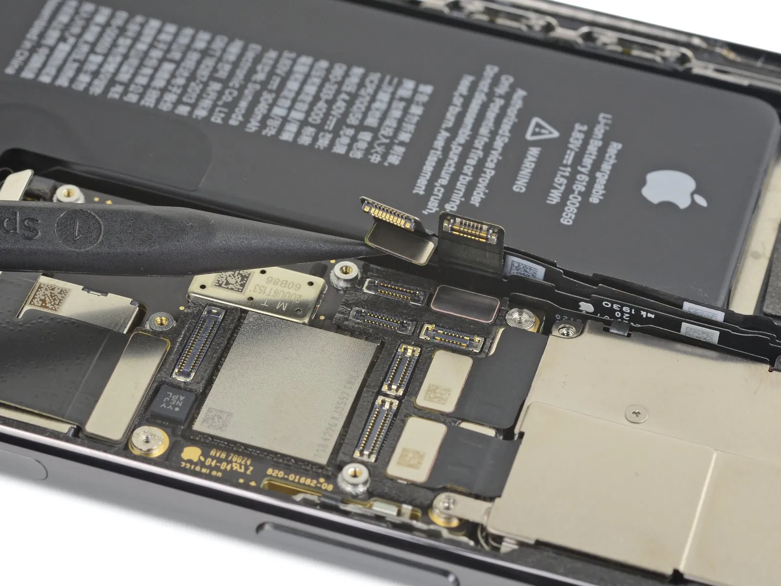
- To gain access to the selfie camera connector located beneath, carefully separate the Face ID cable connectors from the logic board’s surface.
- Release the selfie camera’s connection by applying upward pressure directly on its connector.
Step 23 | Test the replacement camera

Prior to finalizing the camera replacement, a preliminary test of the substitute camera is highly advised to confirm its effectiveness in addressing the problem.
Step 24 | Install the new front camera flex cable
Secure the new camera within its designated receptacle by firmly inserting the connector.
Step 25 | Reconnect the battery
Secure the battery connector by inserting it fully into its designated receptacle.
Step 26

- Power on the device and launch the camera application.
- Confirm proper functionality of both the front-facing and rear-mounted camera modules.
- Successful operation of both cameras indicates that substituting the defective front camera should rectify the fault, allowing repair continuation.
- Should the replacement camera fail to resolve the problem, further steps in this guide will be ineffective; discontinue and reassemble the device.
Step 27 | Disconnect the battery
Employ a spudger tool, or a clean fingernail, to carefully lift the battery connector's retaining clip away from its corresponding socket on the logic board.The battery connector should be disengaged without applying excessive force to avoid damage to the socket or connector itself.To ensure the phone remains powered off during the repair process, gently angle the connector slightly outward, away from the logic board's surface.
This minor deflection minimizes the risk of unintended electrical connection and potential short circuits while working on the device.
Step 28 | Disconnect the OLED display cable
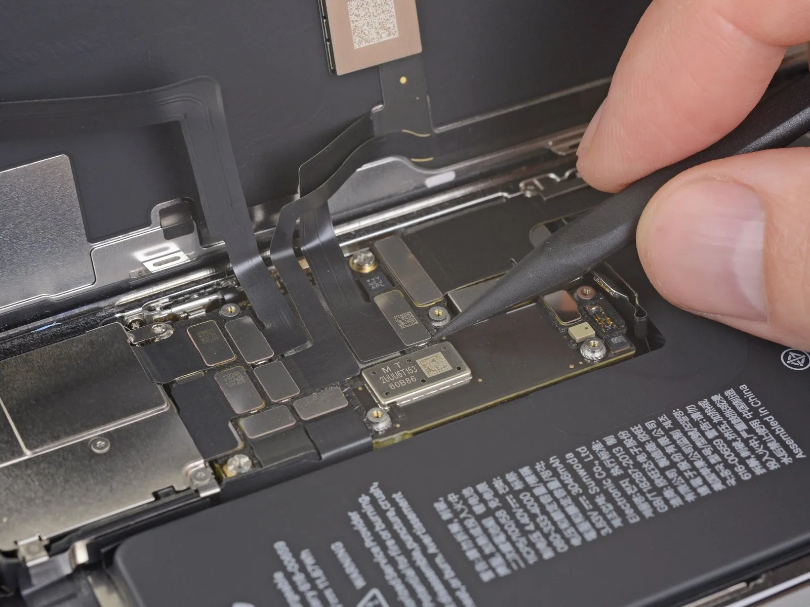
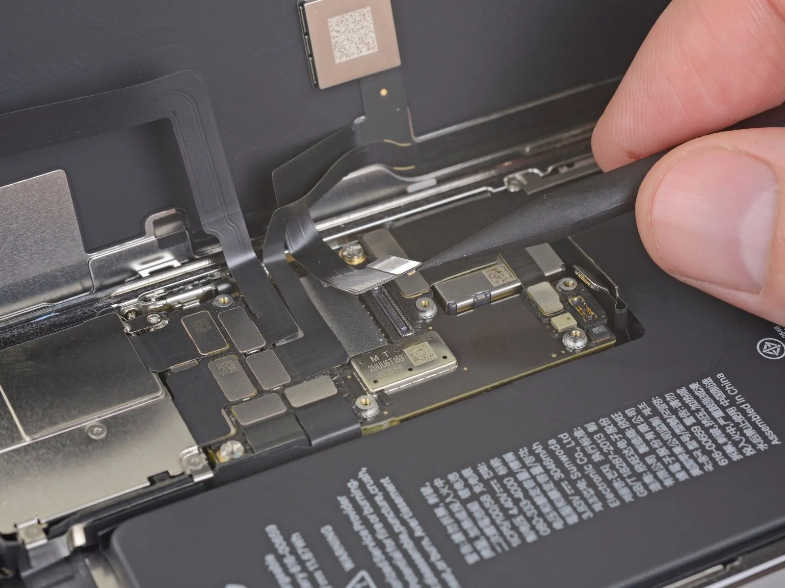
- Employing a spudger or fingernail, carefully separate the OLED panel cable connector.Reconnection requires meticulous alignment; apply pressure to one edge until a click is heard, then repeat the process on the opposing edge.Avoid applying pressure to the central portion of the connector during reattachment to prevent damage.
- Misalignment during the reattachment process can result in bent pins and irreversible damage to the connector.
Step 29 | Disconnect the front sensors + digitizer
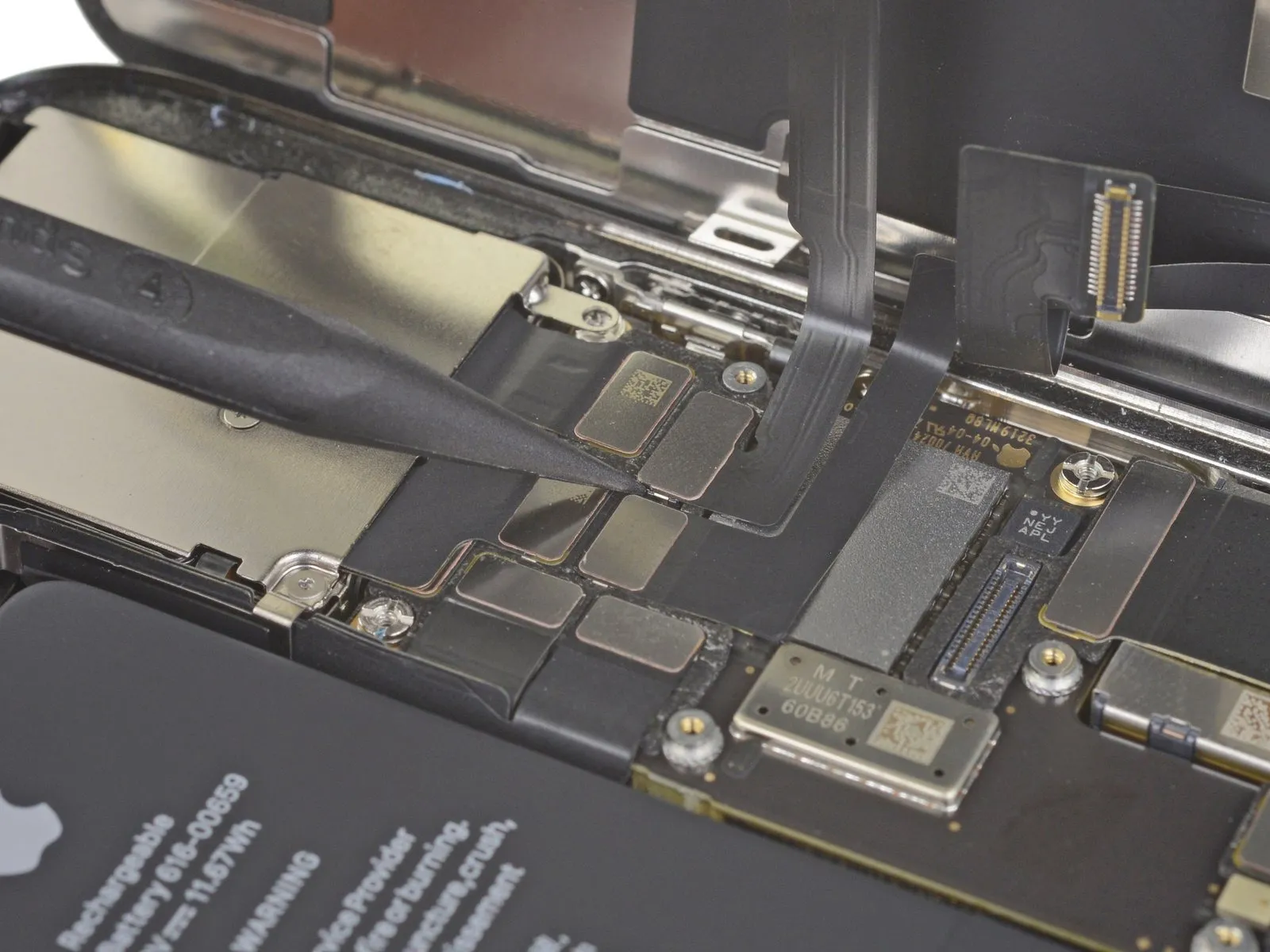
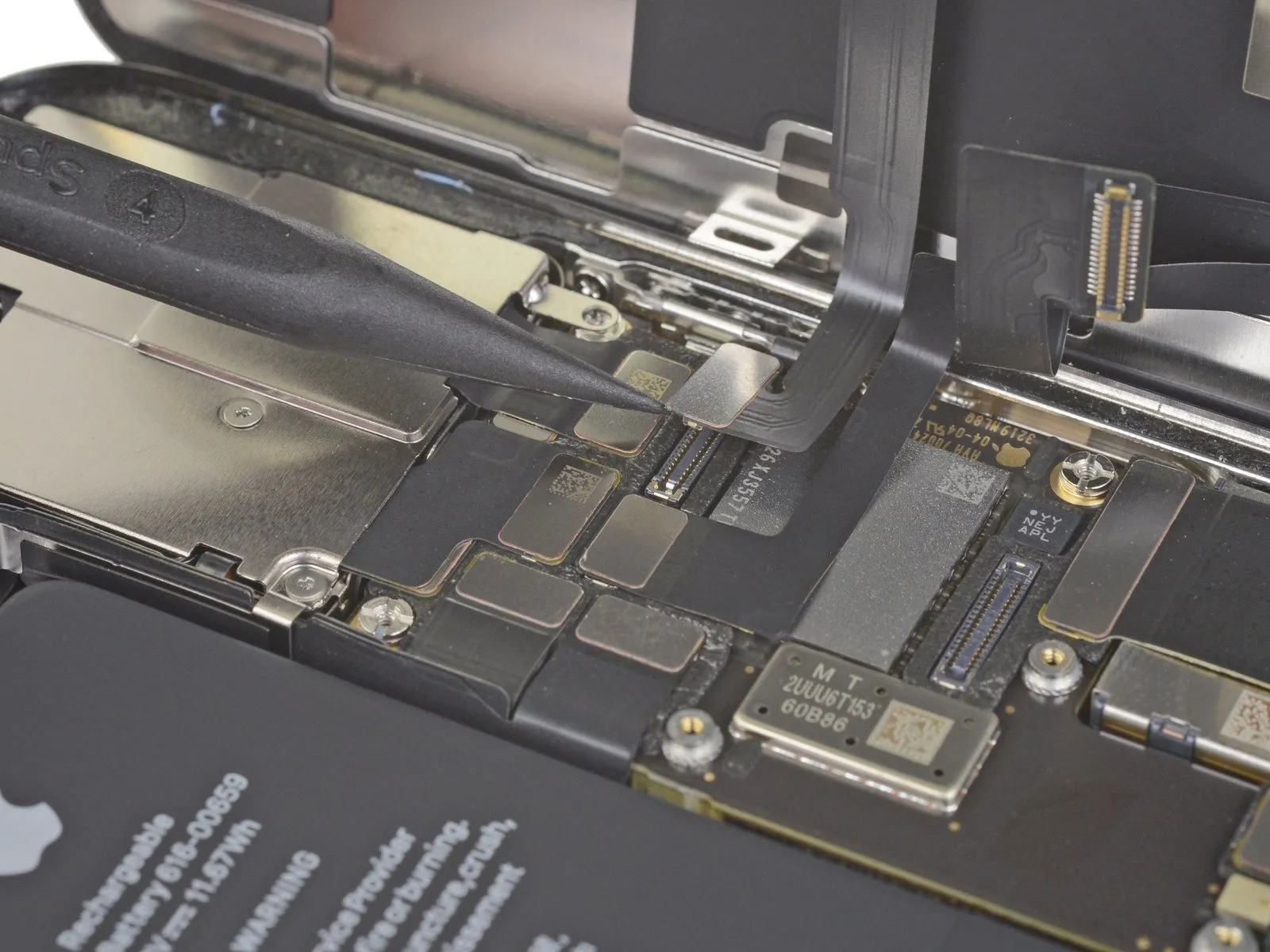
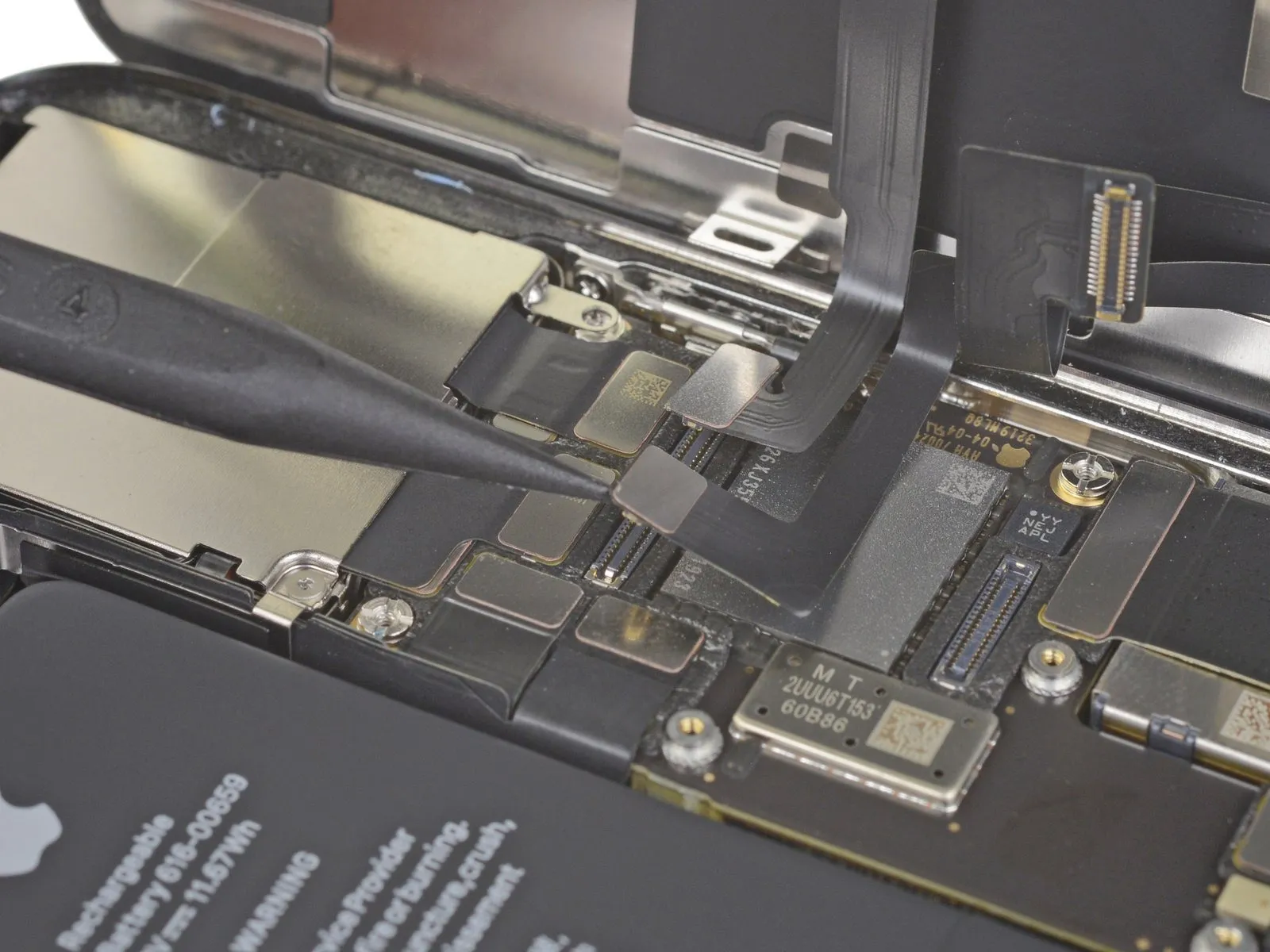
- Employing a spudger or fingernail, carefully separate the front sensor assembly's cable connector.To release the digitizer cable connector, utilize a spudger or fingernail.
- Should the screen exhibit unresponsive touch behavior following the repair process, remove the battery and then firmly reconnect the connector, ensuring a secure click and verifying the socket's cleanliness from debris.A spudger or fingernail can be used for the disconnection.
- Complete re-seating of the connector is necessary to guarantee proper function, and requires verification of a full click and absence of contaminants within the socket.
Step 30 | Remove the display assembly

- Detach the display unit from the device.A temporary halt in the reassembly process is recommended to facilitate replacement of the waterproof adhesive strip that seals the display's perimeter.
- Substitution of the waterproof adhesive is possible at this stage during the reassembly procedure.
Step 31 | Disconnect the selfie cam
- Carefully reposition the Face ID cable connectors, moving them away from the logic board's surface.This action provides access to the selfie camera connector located directly below.
- Sever the connection to the selfie camera module.Achieve disconnection by applying upward force to the connector, ensuring a straight-line motion.
Step 32

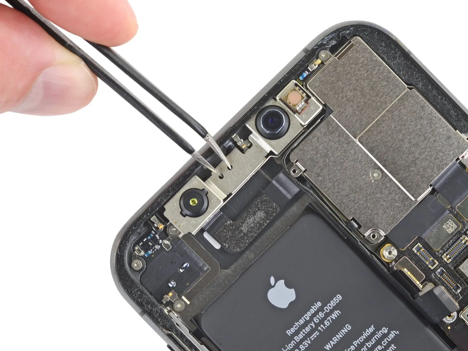
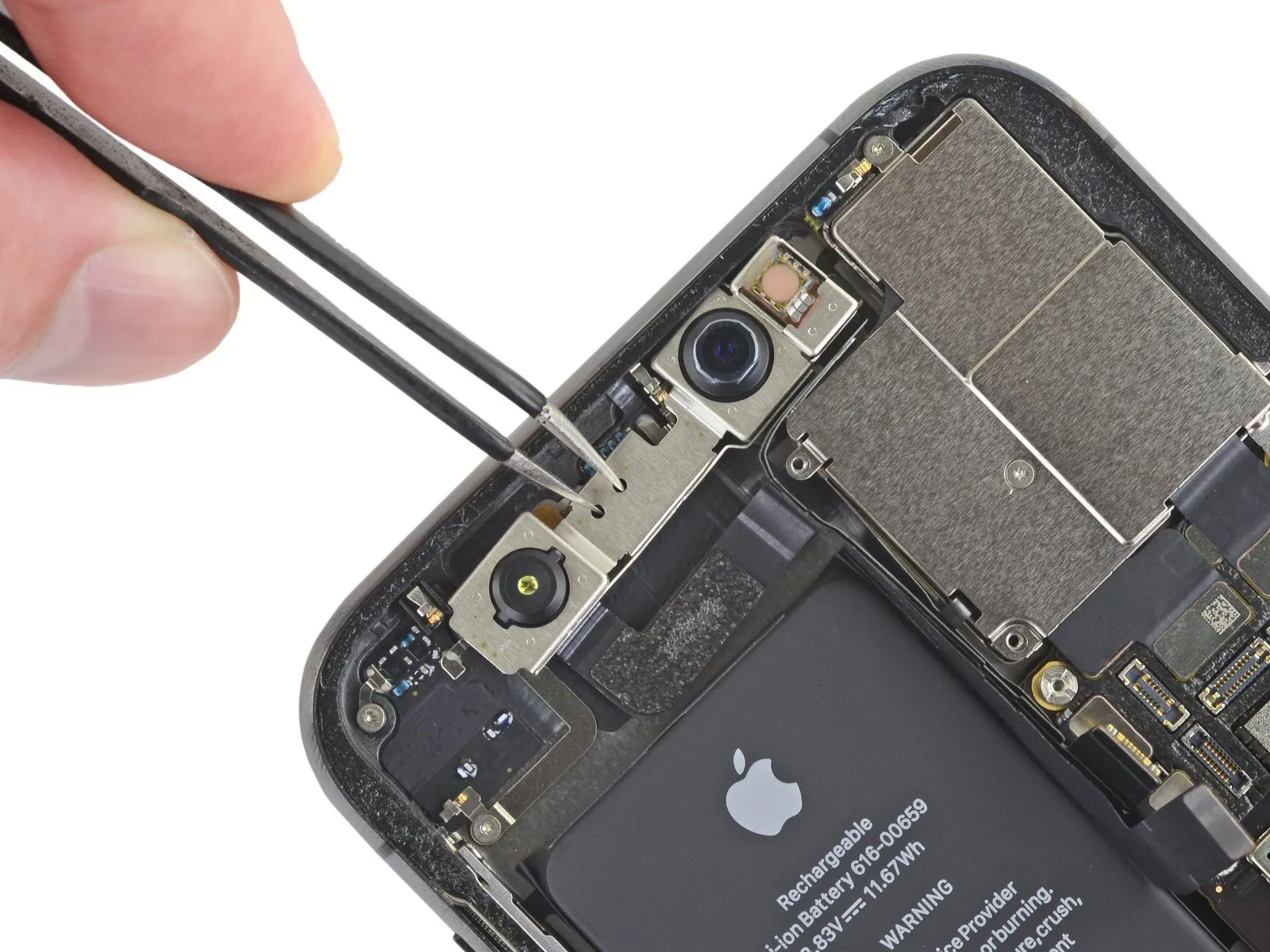
- Utilize tweezers to carefully secure the front camera assembly, ensuring no fingerprints contaminate the sensor surfaces.To disengage the front camera assembly, gently move it downwards and towards the left.
- This sliding motion releases the component from its mounting within the device's housing.The deliberate lateral and downward movement is necessary to overcome the retention mechanism.
Step 33 | Remove the front-facing cameras

Step 34

Step 35


Step 36


- Utilize a Polishing & Grinding Pen, or a Dremel multitool, to remove material from the metal plate's corner edge.The corner of the metal plate necessitates material removal via grinding.A Polishing & Grinding Pen provides a suitable method for this task.Alternatively, a Dremel multitool can be employed to achieve the same result.Employing tweezers, carefully lift the metal plate from its position.
- The metal plate requires separation from its current attachment using a prying action.
Step 37


- Employ a hot air gun to warm the front camera assembly to a temperature of 100 degrees Celsius.Apply heat for a duration of 30 seconds to soften the adhesive securing the front camera to the device's frame.Protect the front camera area with a clean, lint-free cloth during the separation process.Gently apply pressure to the protected area with the cloth to aid in adhesive release.Carefully detach the defective front camera component from the frame.The targeted temperature is 100 °C to effectively loosen the adhesive bond.A heating duration of 30 seconds is recommended for optimal adhesive softening.
- A lint-free wipe is essential to prevent contamination during the repair.Gentle pressure application minimizes the risk of further damage to surrounding components.The removal process should be executed with precision to avoid component breakage.
- Adhesive softening facilitates the separation of the front camera from the frame structure.Maintaining a controlled temperature is crucial to prevent overheating and component degradation.Complete the removal by extracting the damaged front camera from its mounting position.
Step 38


- Carefully dispense a minimal amount of adhesive along the frame's perimeter, specifically around the camera's aperture.
- Proceed with the installation of the replacement front camera component.Ensure precise alignment during insertion of the front camera into its designated recess, preventing adhesive contact with the lens surface.Proper positioning of the camera is essential to maintain optical clarity and avoid adhesive contamination.
Step 39

- To secure the component, spread adhesive across its rear surface.The camera's frame should be pressed with considerable force against the adhesive-coated area.Position the front camera within the designated holder.
- A retainer must be situated atop the glued camera and frame assembly.This retainer prevents movement while the adhesive achieves full bonding strength.Allow sufficient drying time for the adhesive to cure completely.
Step 40


- Allow a sixty-minute duration before detaching the front camera module.The front camera component is now successfully substituted.Detach the Kapton tape adhering to the infrared camera and dot projector with precision.Secure the replacement front camera module in its designated location.Verify proper functionality by initiating a test sequence.
Power on the device to confirm operational status. - Ensure both the primary and secondary cameras are producing images.Confirm the proper operation of the Face ID authentication system.Successful completion of the repair involves verification of all camera and biometric functionalities.