iPhone 12 Front-Facing Cameras Replacement
This document details the procedure for disassembling and substituting the front-facing camera module, commonly referred to as the "selfie cam," within an iPhone 12.Be advised that substituting this component will disable the Face ID functionality.The described repair procedure will resolve issues with a malfunctioning front camera; however, on iOS versions 17.6 and prior, Face ID reactivation necessitates service from Apple or a certified Apple technician.
- With iOS 18 and subsequent releases, it becomes possible to reconfigure newly installed, authentic front cameras utilizing Apple's Repair Assistant application.The replacement of the front camera assembly necessitates specialized tools and expertise to prevent further damage to the device.
- Successful completion of this repair requires careful adherence to the outlined steps and proper handling of delicate internal components.
- It is crucial to understand that unauthorized repairs or the use of non-genuine parts may void the device's warranty and compromise its functionality.
Step 1 | Remove the pentalobe screws
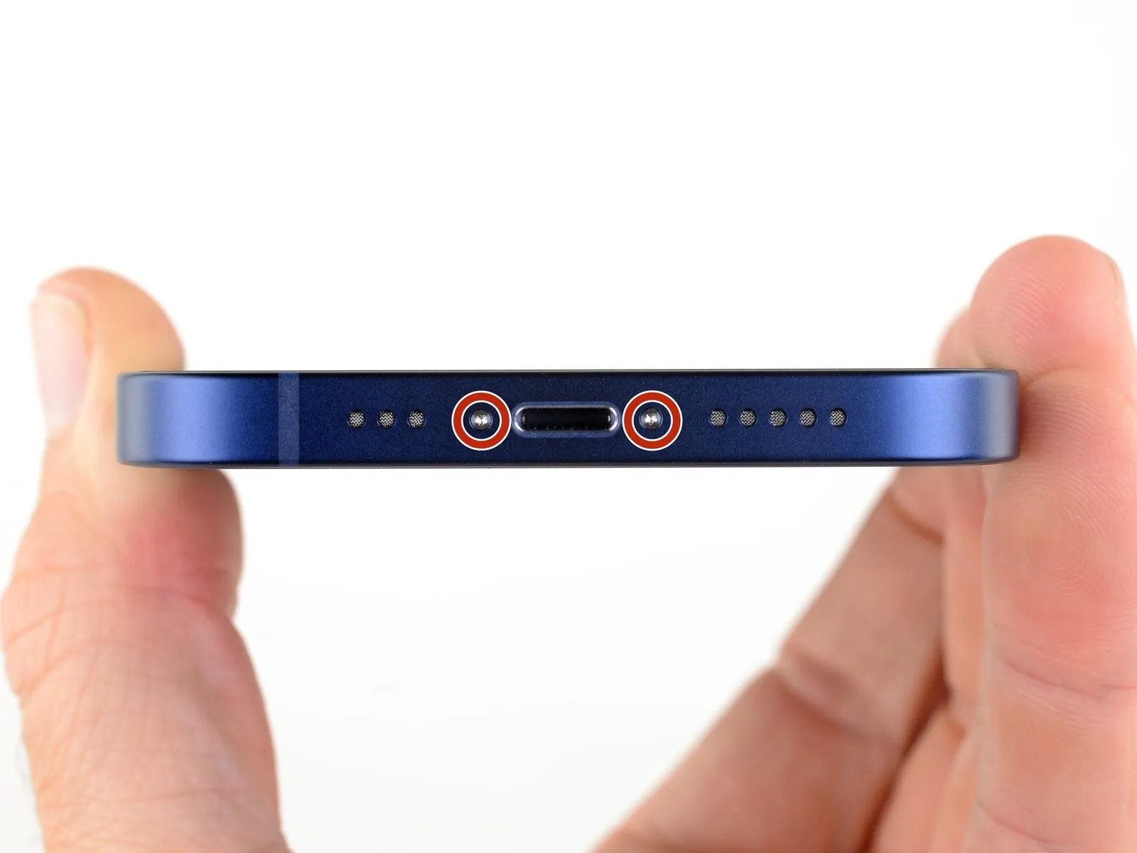
- Thoroughly clean any dust or debris from the iPhone's exterior surface to prevent scratching during disassembly.
- Use appropriate tools to unscrew and remove the pair of 6.75 mm pentalobe screws located on the iPhone's lower edge.
Step 2 | Mark your opening picks


- To prevent over-insertion, use a permanent marker to indicate a 3-millimeter distance from the tool's tip.
- For enhanced precision, consider marking the tool's other corners with varying measurements.
- As an alternative method, secure a coin to the tool's tip using adhesive tape, positioning it 3 millimeters from the end.
Step 3 | Tape over any cracks


- Apply multiple layers of transparent packing tape across the iPhone's display surface, ensuring complete coverage.
- Always utilize eye protection to guard against glass fragments that may become dislodged during the repair process.
- Should the suction cup fail to maintain adhesion during subsequent procedures, create a handle from a robust adhesive tape, like duct tape, to carefully separate the screen.
- As a last resort, secure the suction cup to the display using superglue to facilitate screen lifting.
Step 4 | Anti-Clamp instructions


- Detailed guidance concerning the operation of the Anti-Clamp is accessible through a separate instructional document.To disengage the Anti-Clamp’s securing mechanism, retract the blue handle towards the rear.
- Position the tool’s arms across either the left or right side of the iPhone’s frame.
- Place the suction cups in proximity to the iPhone’s lower border, ensuring one is situated on the front surface and the other on the rear.
- Apply a compressive force to the cups to establish a vacuum seal on the intended location.
- Should the iPhone’s exterior exhibit excessive slipperiness, hindering the Anti-Clamp’s ability to maintain adhesion, applying adhesive tape can enhance surface friction.
- Employing tape can provide a more secure interface if the Anti-Clamp's grip is insufficient due to the iPhone's surface properties.
Step 5


- Rotate the handle in a clockwise direction, completing a full 360-degree revolution, or until the suction cups exhibit signs of deformation.
- Maintain precise alignment between the suction cups; should misalignment occur, slightly reduce the suction force and reposition the arm components.
Step 6


- Apply heat along the iPhone's lower edge utilizing a hair dryer, ensuring the screen's surface temperature reaches a point where it feels uncomfortably warm to the touch.
- Refer to a dedicated guide for detailed instructions regarding the proper operation of a hair dryer.
- Allow a sixty-second interval to permit the adhesive to soften and create a discernible separation.
- Introduce an opening pick into the space between the screen and the plastic bezel, positioning it where the Anti-Clamp has generated a noticeable gap.
- Should the Anti-Clamp fail to produce an adequate separation, increase the heat application to the area and rotate the handle incrementally by ninety degrees.
- Avoid rotating the handle beyond a ninety-degree increment at any time, and observe a sixty-second pause between each rotation to allow the Anti-Clamp and time to facilitate the separation.
- Proceed to bypass the following three steps in the repair process.
Step 7 | Heat the bottom edge

Important consideration:Avoid prolonged, concentrated heat application from the hair dryer to prevent localized overheating.
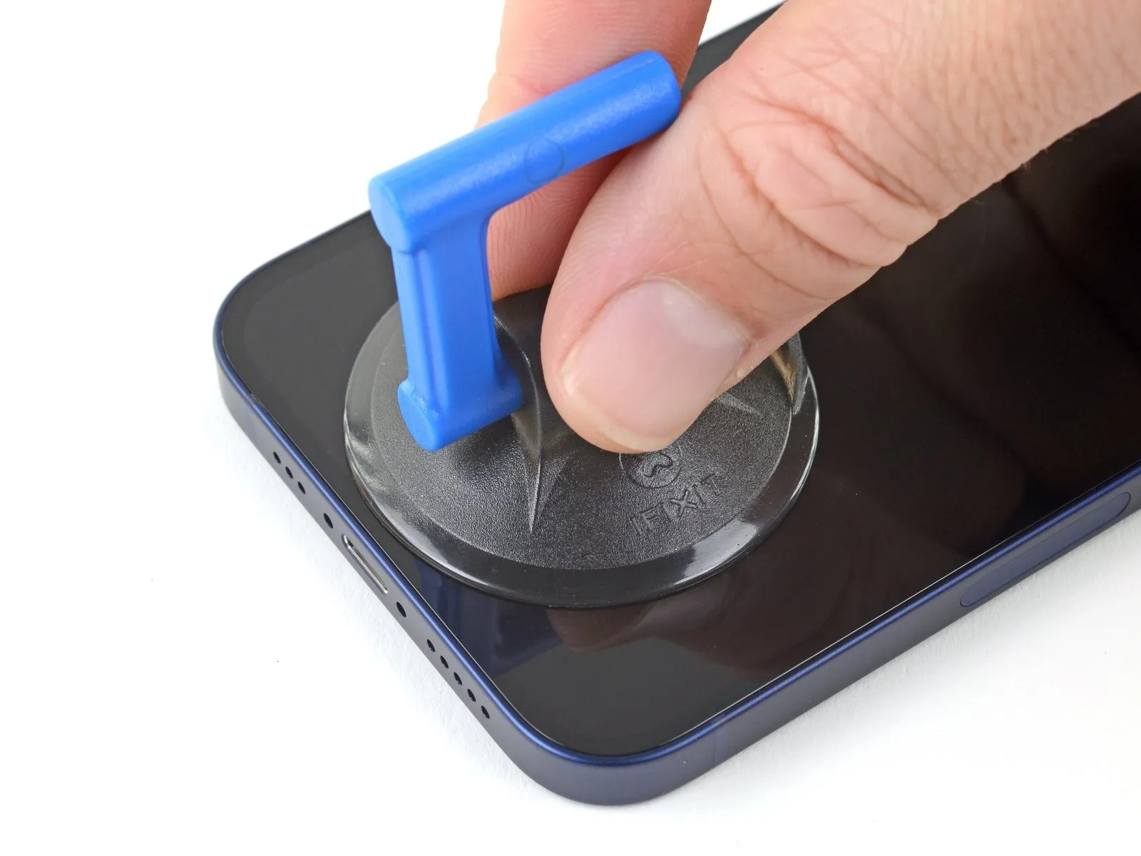
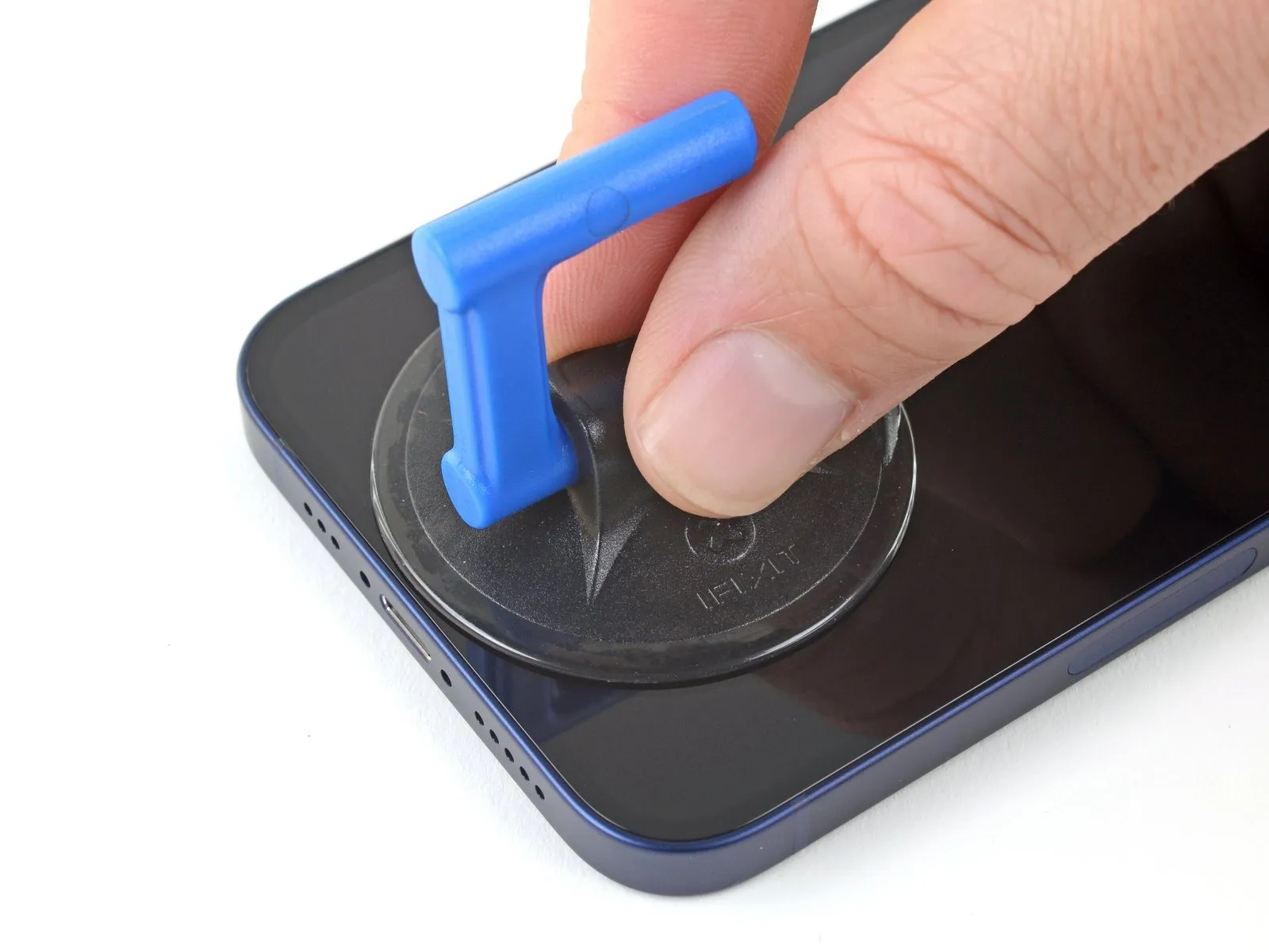
Step 8 | Apply a suction cup
Step 9 | Lift the screen slightly
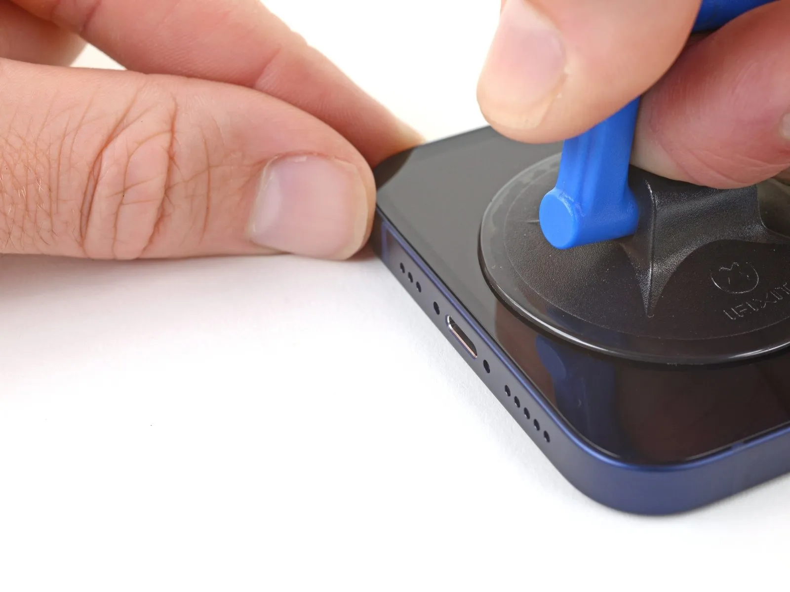
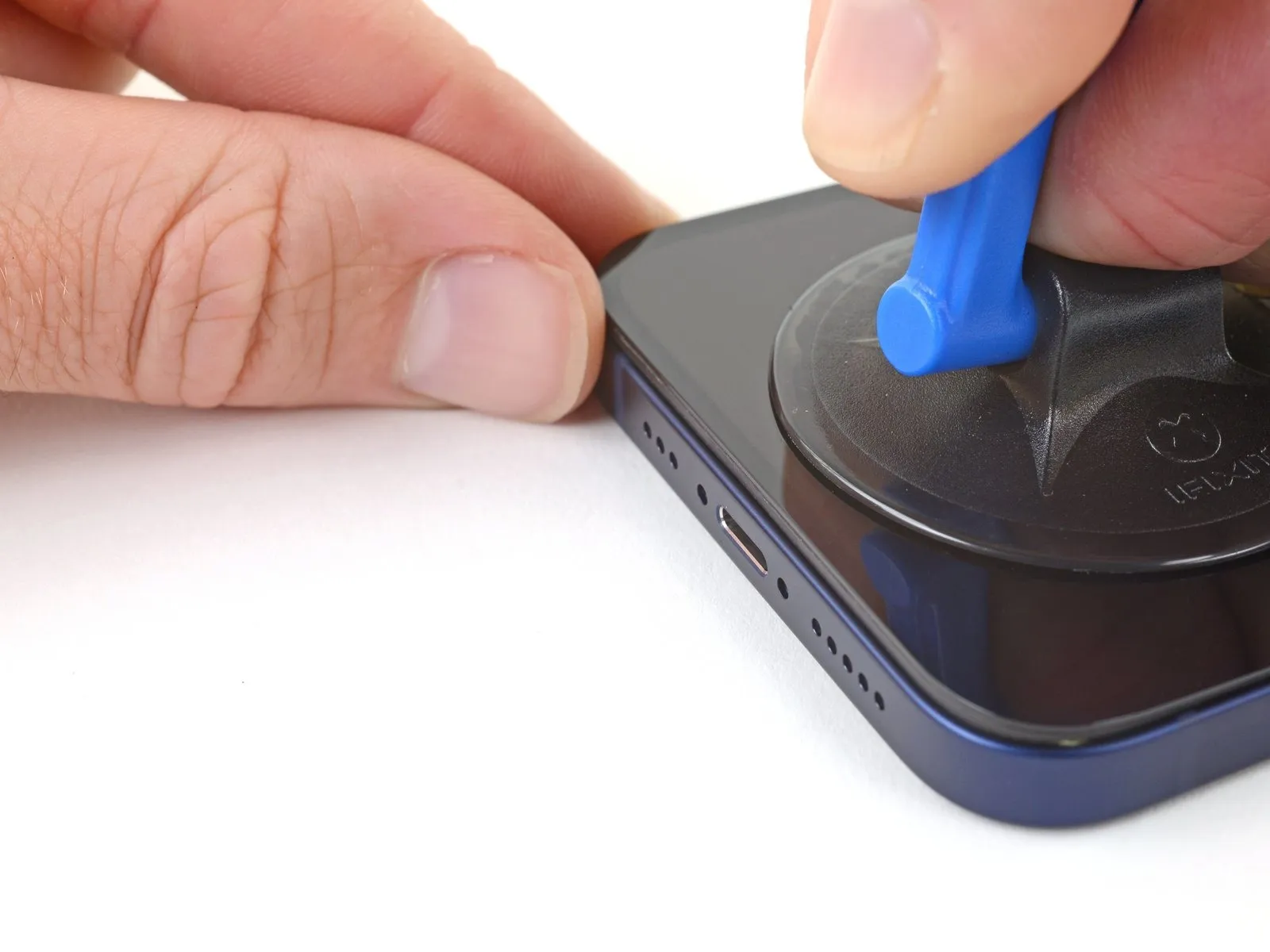
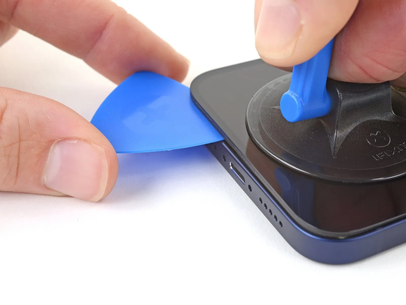
- Carefully slide a separation tool into the space formed between the display and the surrounding plastic trim, ensuring it does not contact the display surface directly.
- Position the separation tool beneath the substantial plastic trim to prevent potential damage to the display panel; a visible separation should be apparent, and the tool should move freely without obstruction; if a separation is not visible, increase the upward displacement of the display.
- The screen is secured by a robust, waterproof sealant; overcoming this adhesion requires considerable force; if initial separation proves difficult, apply localized heat and gently oscillate the display to reduce the sealant's strength, facilitating tool insertion.
Step 10 | Separate the bottom edge adhesive


- Employ a reciprocating motion with the pick across the lower edge to effectively sever the adhesive bond.
- Maintain the pick's position within the lower-right corner to inhibit adhesive re-adhesion.
Step 11 | Heat the right edge


Step 12 | Separate the right adhesive
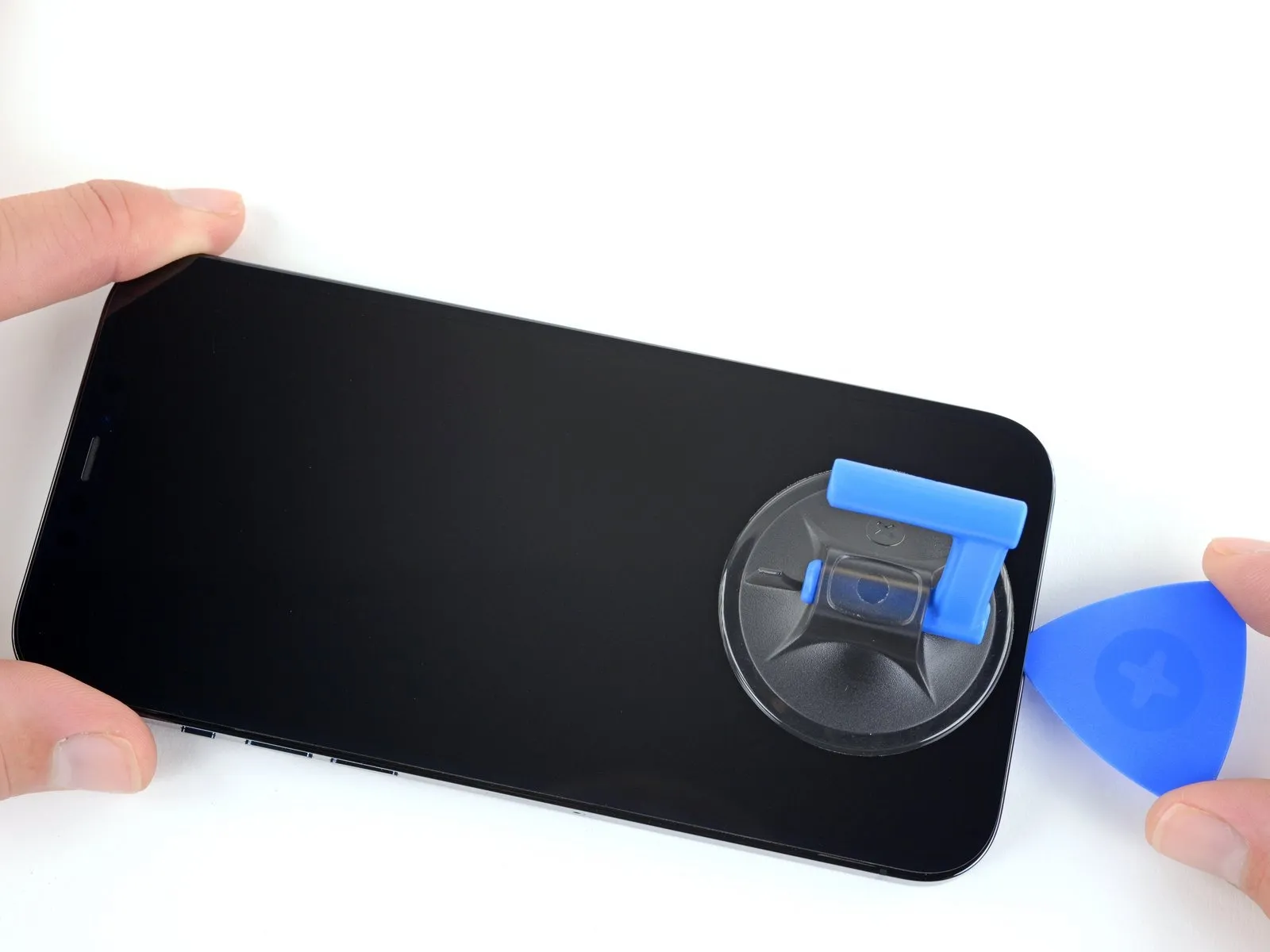


- Utilize a specialized opening pick, carefully maneuvering it along the lower-right perimeter of the iPhone to release the securing adhesive.
- Progressively advance the pick upwards along the right side of the iPhone's casing until the upper-right corner is reached.
- Maintain a maximum insertion depth of 3 millimeters for the pick to prevent potential harm to delicate internal parts.
- Position the opening pick within the top-right corner of the device before proceeding with subsequent steps.
Step 13 | Heat the top edge

To facilitate separation, apply warmth to the iPhone's upper perimeter using a hair dryer, ensuring the screen surface reaches a temperature just beyond comfortable touch.
Step 14 | Separate the top adhesive


- Employ an opening pick, carefully maneuvering it along the upper-right edge of the iPhone's casing to release the adhesive bond.
- Ensure the pick's insertion depth remains limited to a maximum of 3 millimeters to prevent potential harm to the delicate top sensors.Maintain the pick's position within the upper-left corner of the device as you proceed with subsequent steps.Exceeding the 3 mm depth limit carries a risk of compromising the functionality of the iPhone's upper sensors.
- The adhesive securing the iPhone's enclosure is released by gently sliding the opening pick along the top edge.
Step 15 | Heat the left edge


To facilitate separation, apply warmth to the left side of the iPhone's enclosure utilizing a hair dryer, ensuring the screen surface reaches a temperature just beyond comfortable touch.
Step 16 | Separate the left adhesive
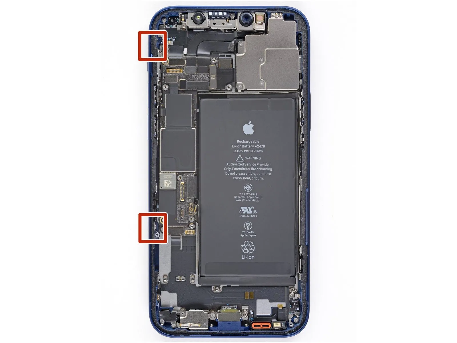


- To prevent damage to the display's connection cables, ensure your opening tool does not penetrate beyond a depth of 2 millimeters along the left side.The two cables linking the display assembly to the device's mainboard are located near the left edge, so exercise caution.Employ a pivoting motion with your opening tool around the upper-left corner of the screen's perimeter.
- Advance your tool along the left edge to sever the adhesive bond securing the display.
- Should adhesive separation prove difficult, applying localized heat to the left edge may facilitate the process.
- Reheating the left edge can soften the adhesive, easing separation if initial attempts are unsuccessful.
Step 17 | Open the iPhone
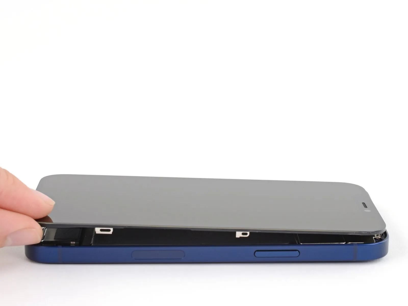
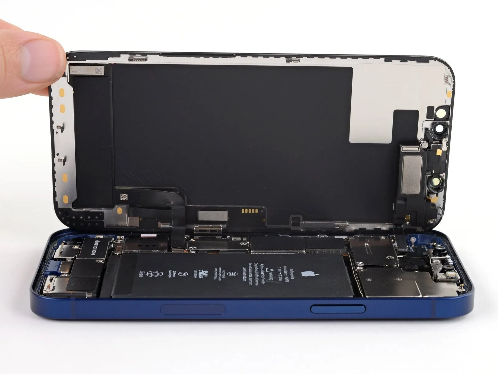
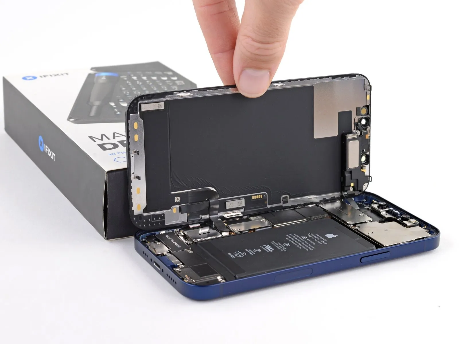
- Orient the iPhone, positioning the right side within your view.
- Initiate the opening process by pivoting the display upwards from the right side, mimicking the action of opening a book's cover.
- Avoid completely detaching the display at this stage, since delicate ribbon cables remain connected to the logic board.
- Secure the display in an upright position using a support to maintain access to the internal components.
- When reassembling, position the display, ensuring the top edge clips are aligned, and then apply gentle pressure to the top edge before fully securing the display with a snapping motion; if resistance is encountered, inspect the display's perimeter clips for any deformation.
Step 18 | Unscrew the battery and display connector cover
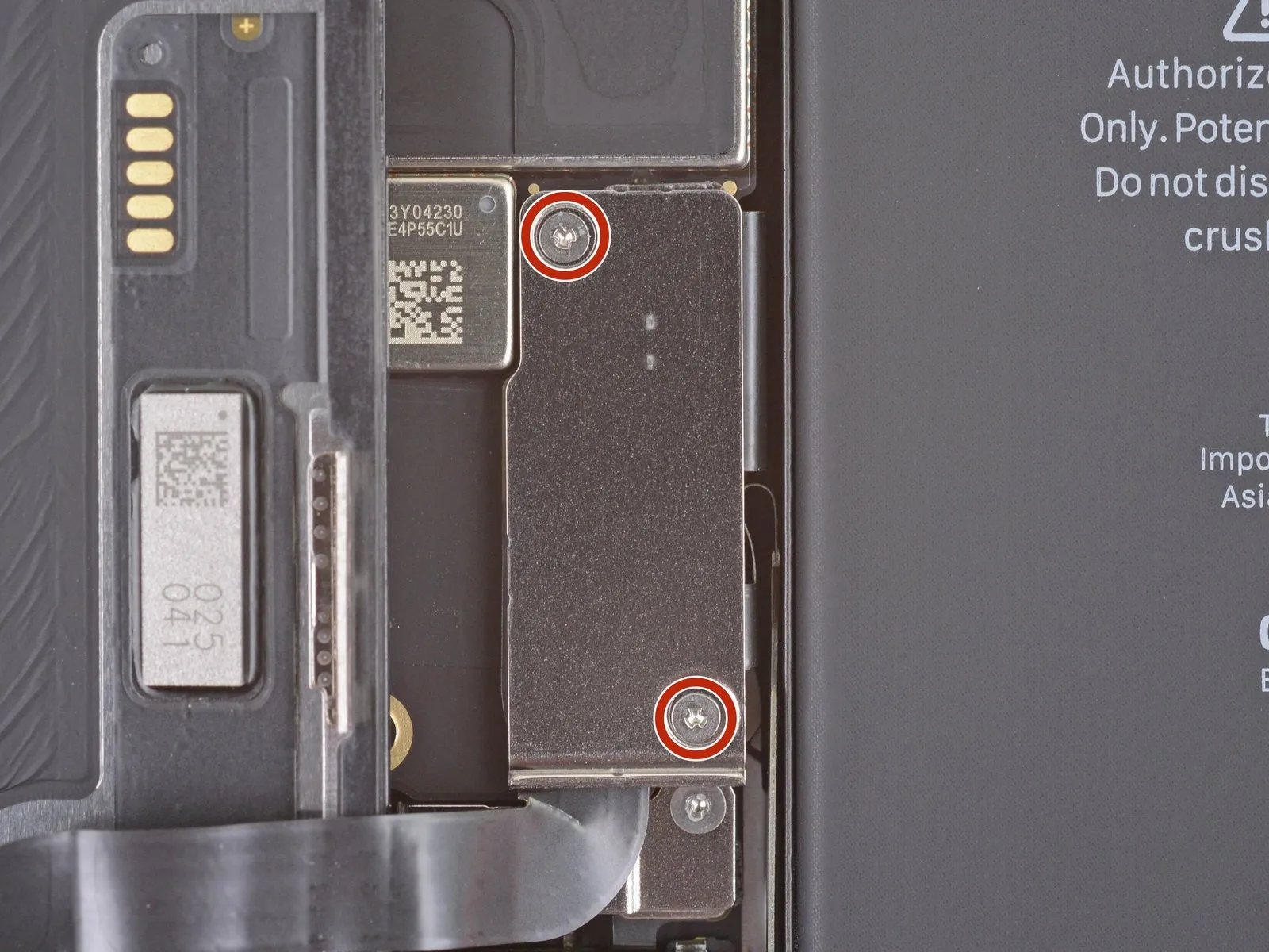
- Detach the battery and display connector cover by unscrewing two Y000 screws, each measuring 1.1 mm in length.Carefully organize all screws during disassembly, ensuring each is returned to its original location to prevent potential damage to the iPhone's internal components.To verify proper functionality, briefly power on the iPhone and perform a full system test at this stage of the repair process.
- Prior to securing the display during reassembly, completely shut down the iPhone to avoid any unintended operational issues.
- Confirming all features are working correctly before permanently affixing the display is a recommended practice to ensure a successful repair.
Step 19 | Remove the battery and display connector cover
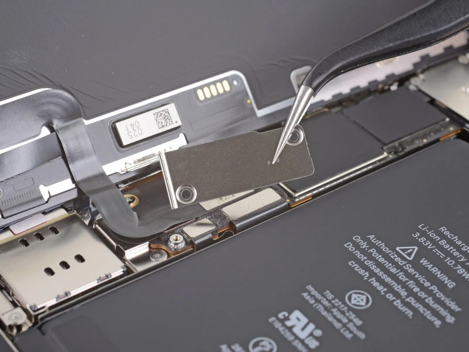
Step 20 | Disconnect the battery
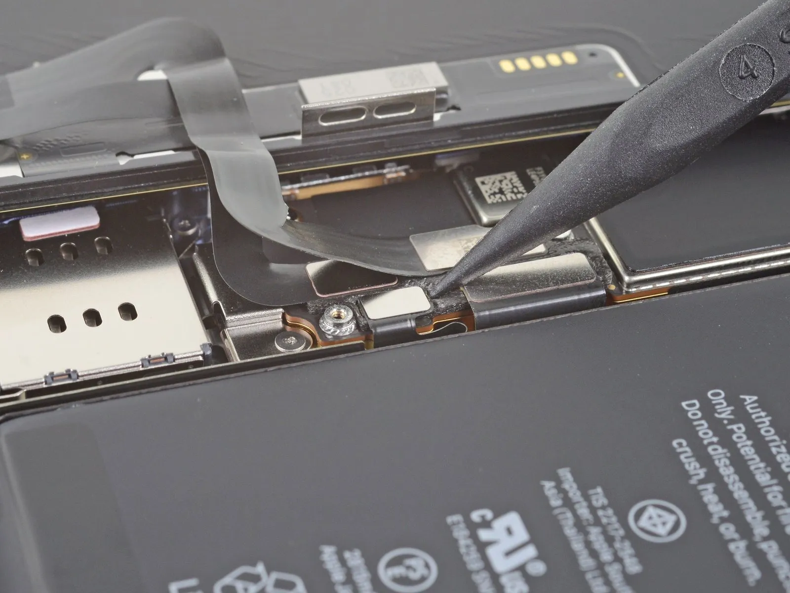
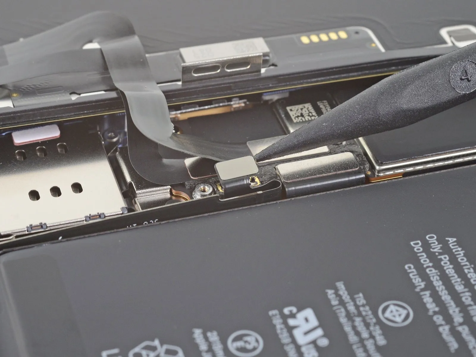
- Employ a spudger or a pristine fingernail to elevate the battery connector from its corresponding receptacle on the logic board.
- Exercise caution to avoid harming the black silicone seals that encircle this and other board connections, as these seals offer supplemental defense against water and dust ingress.
- Slightly deflect the connector away from the logic board to inhibit unintended contact with the socket and subsequent power delivery to the device during the repair process.
Step 21 | Disconnect the display cable

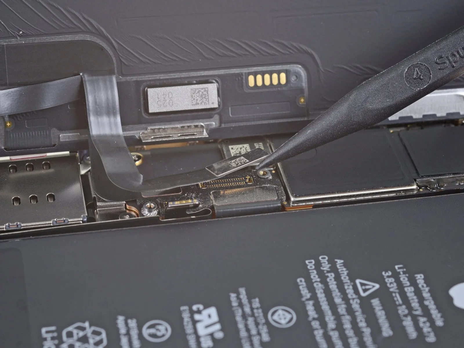
- Misalignment during reattachment risks bending the internal pins.
- Pin bending can result in irreversible component failure.
Step 22 | Disconnect the digitizer cable
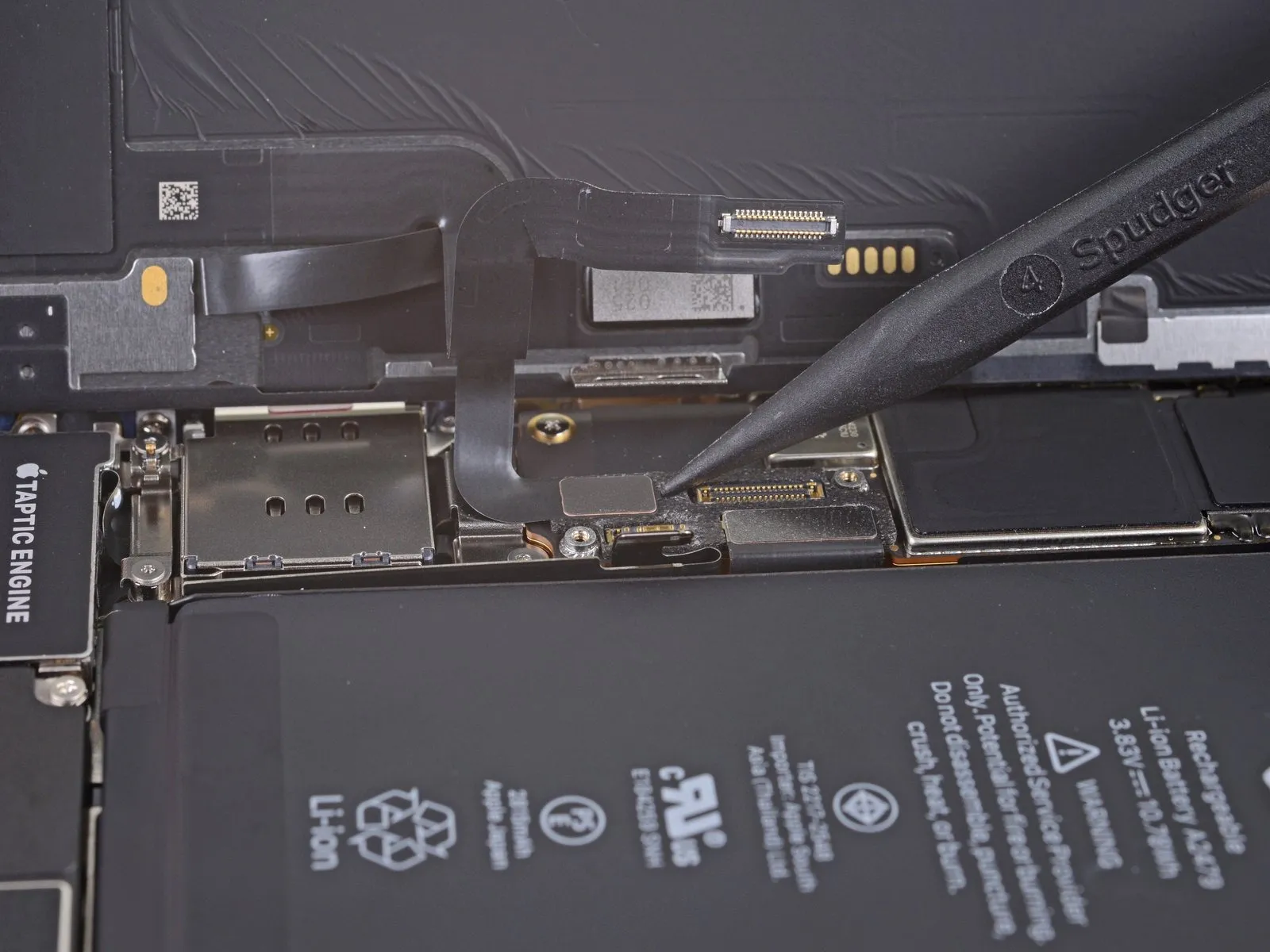
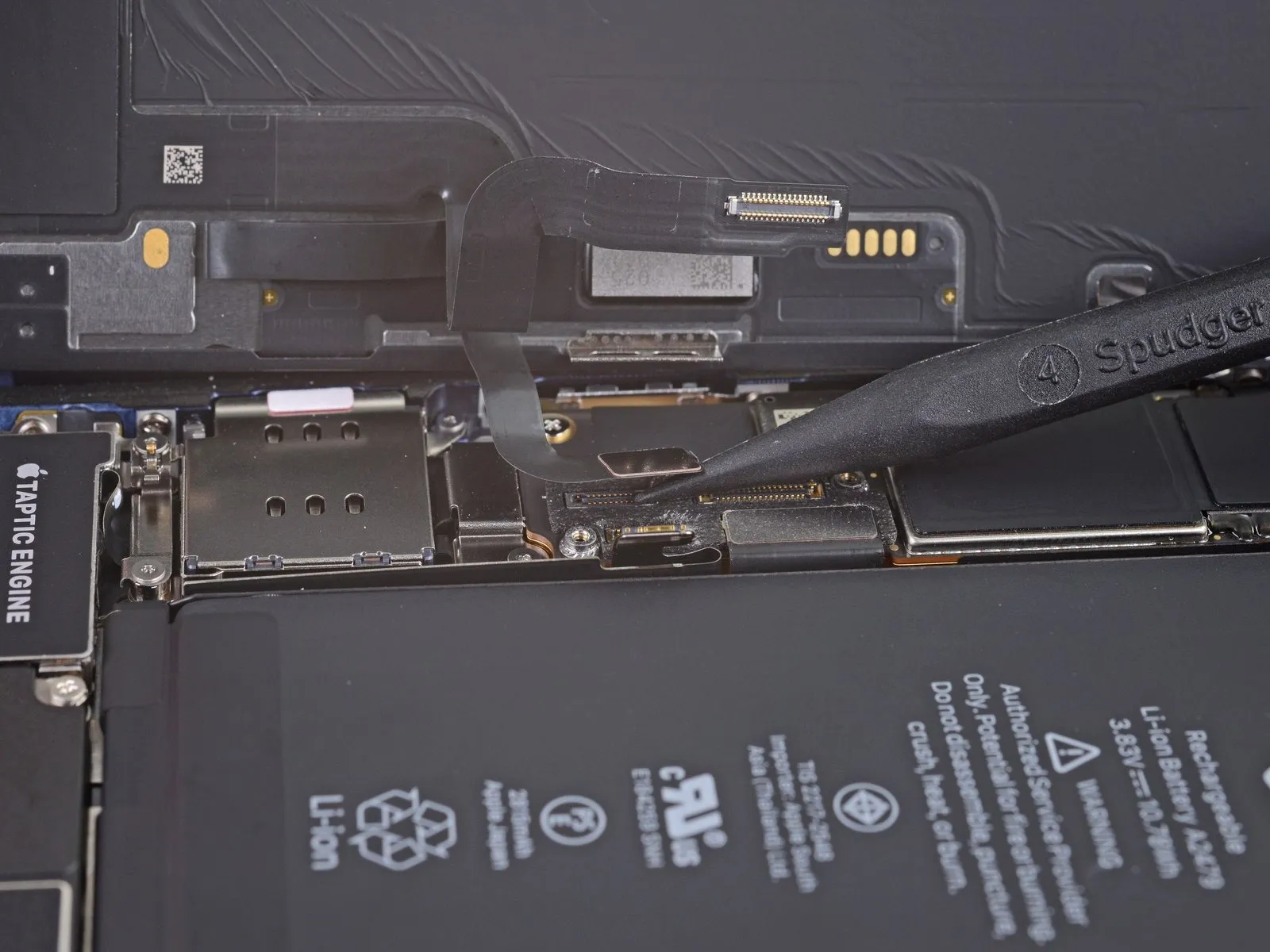
- A proper seating of the connector is crucial for restoring full touchscreen functionality.
- This step is vital to prevent potential operational issues resulting from a loose or contaminated connection.
Step 23 | Unscrew the front sensor connector cover
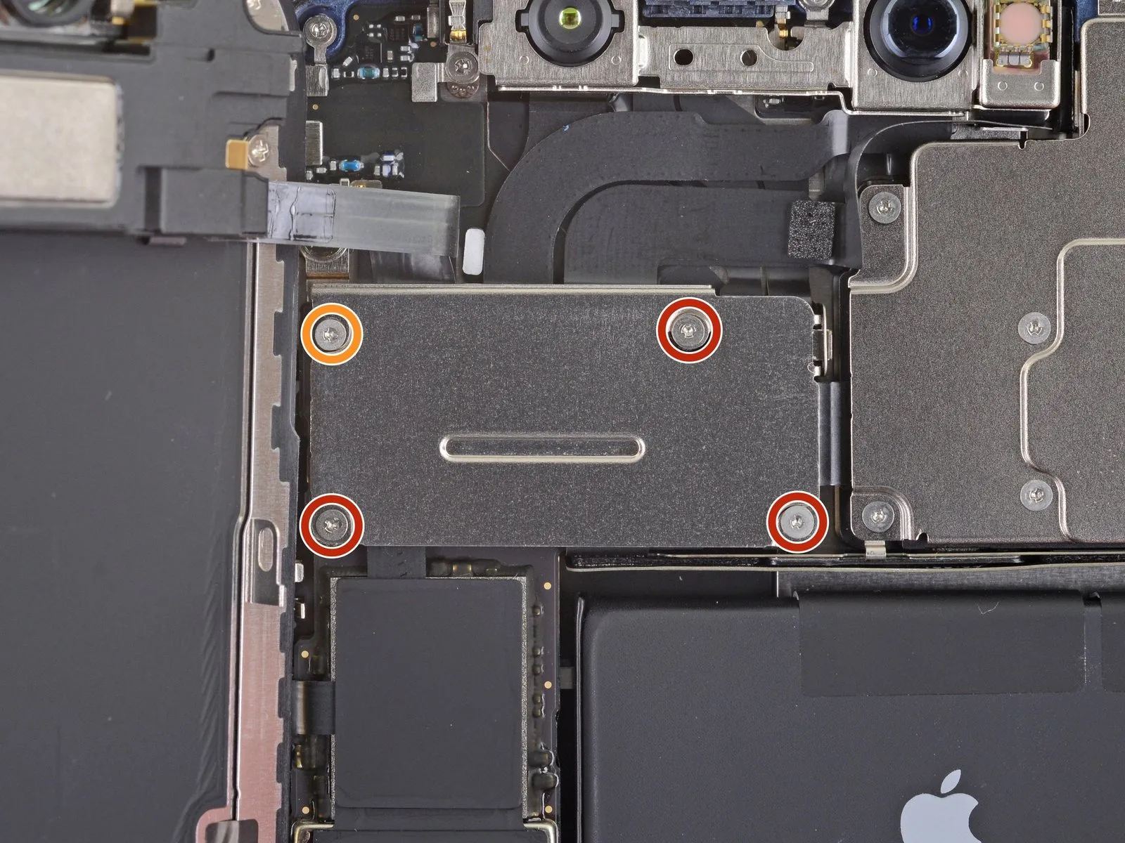
- A single screw, differing in length, is also utilized.This particular screw has a length of 1.4 millimeters.Carefully unscrew the fasteners to avoid damage.
- Ensure the driver bit is properly seated in the screw head.Maintain consistent downward pressure while rotating the driver.Note the screw lengths for reassembly purposes.
Step 24 | Remove the front sensor connector cover
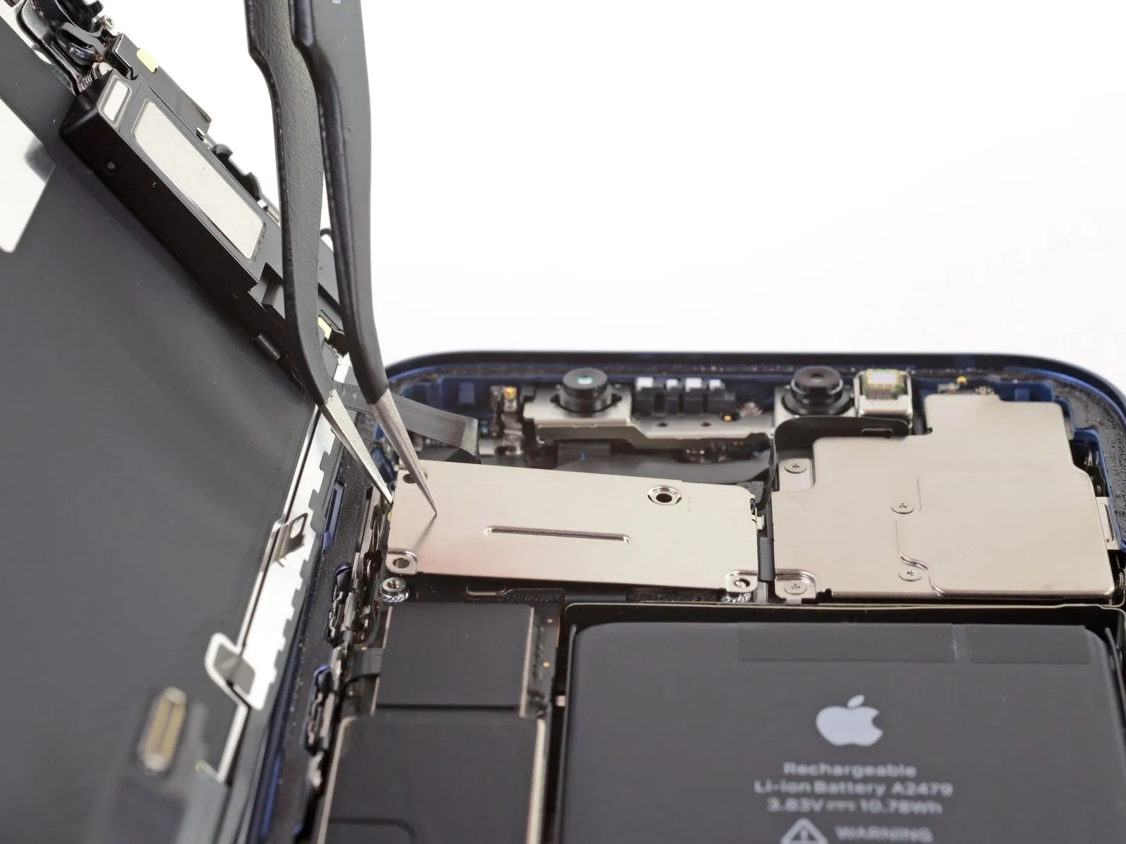
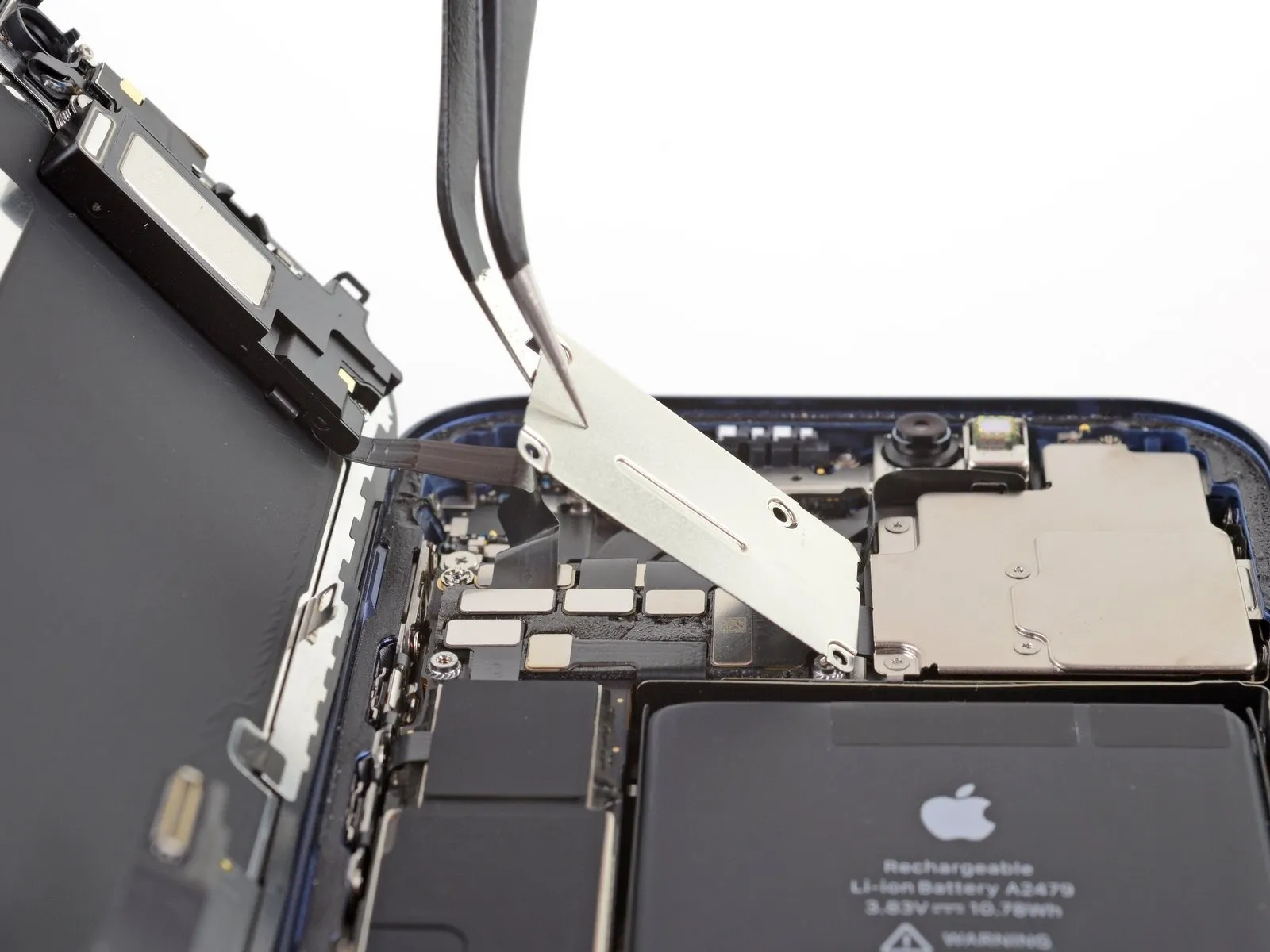
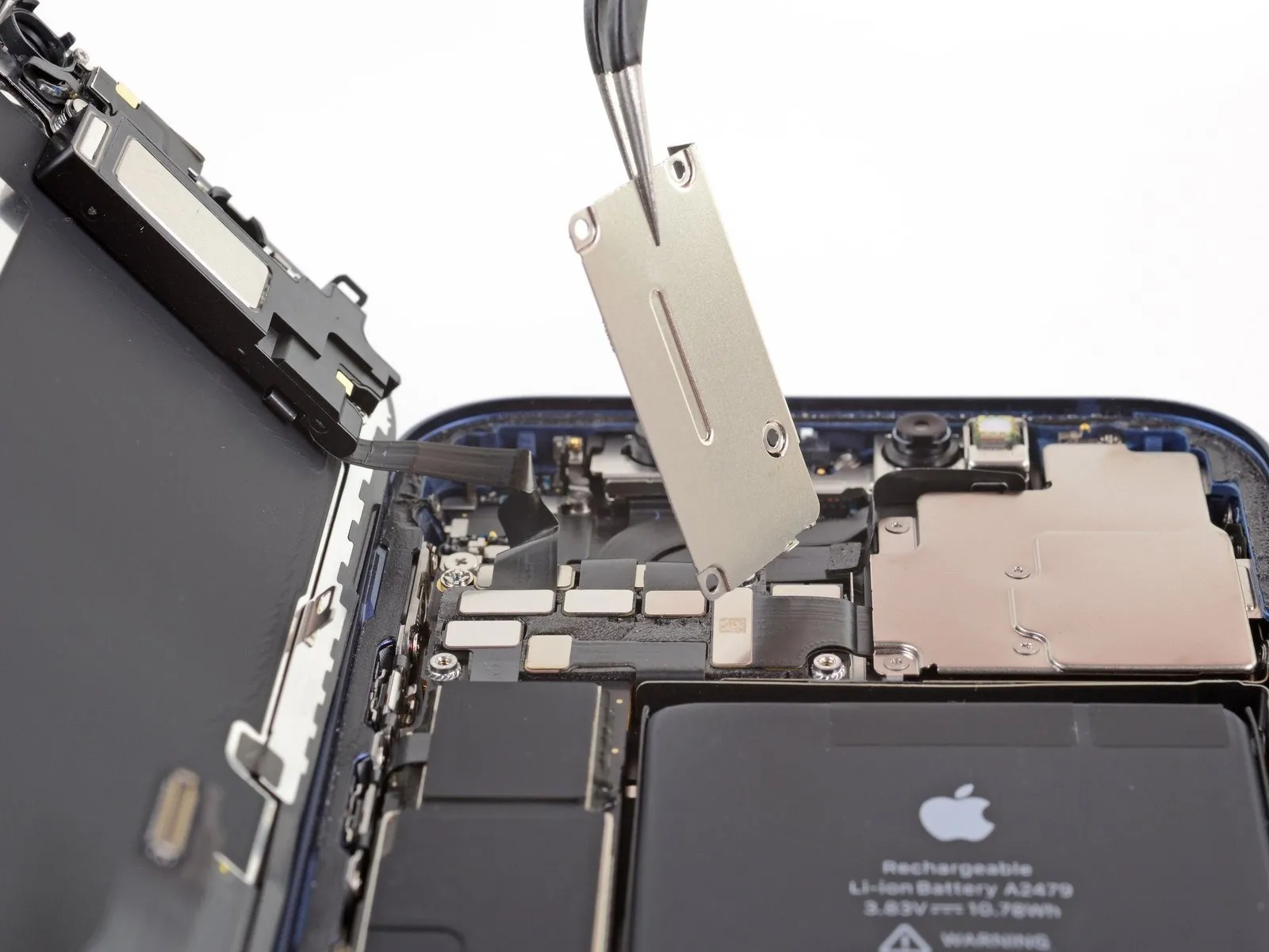
- Detach the cover completely.
- When reattaching, initially engage the right-side clip into its corresponding receptacle.
- Subsequently, align and secure the remainder of the cover.
Step 25 | Disconnect the front sensors
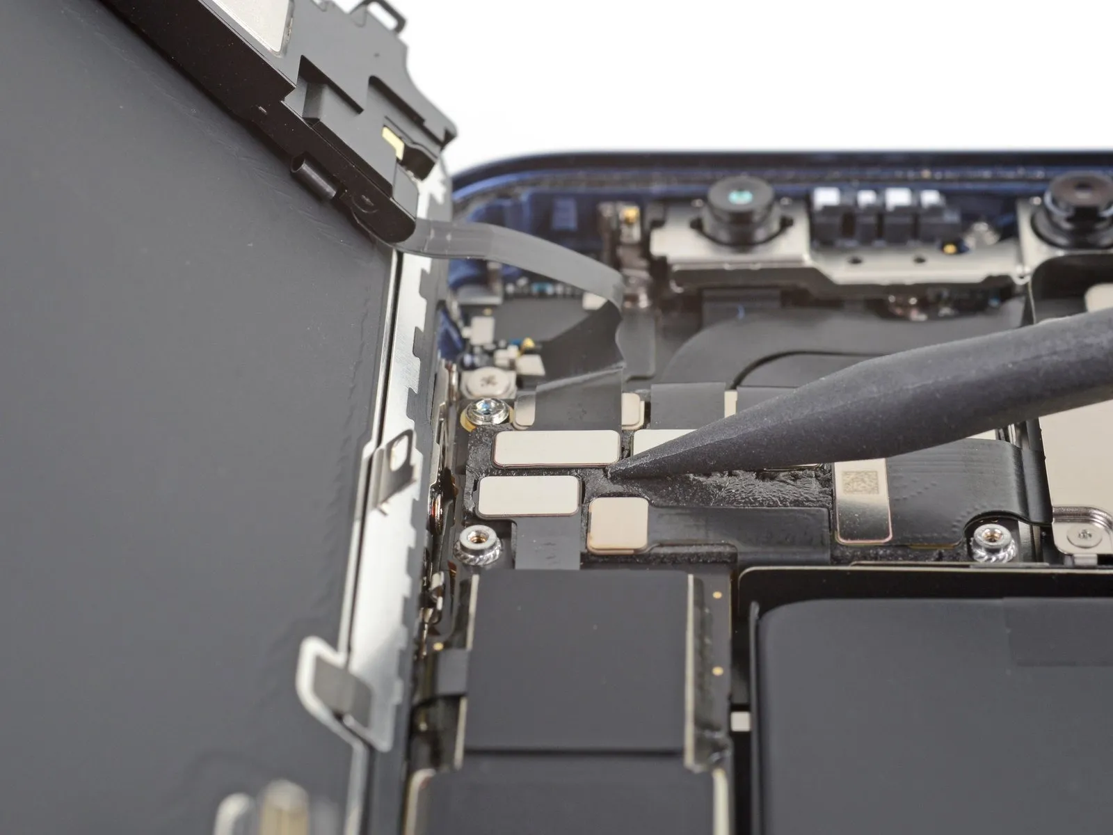
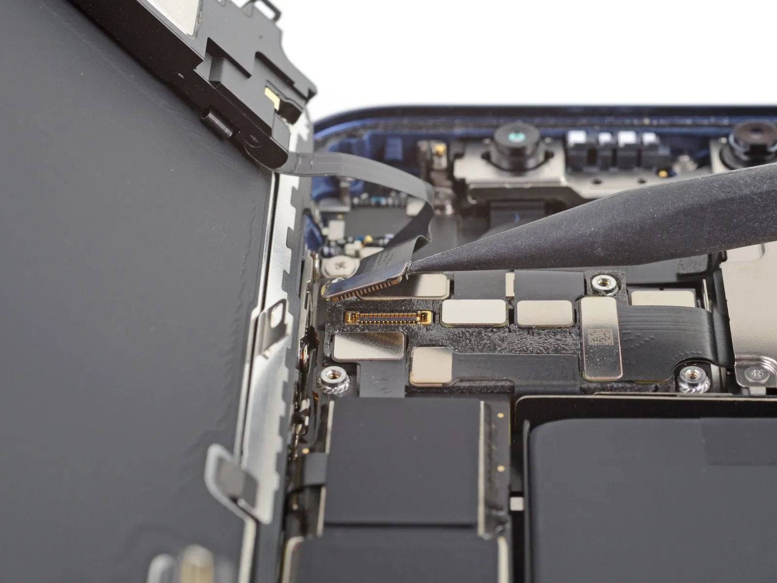
Step 26 | Remove the display assembly
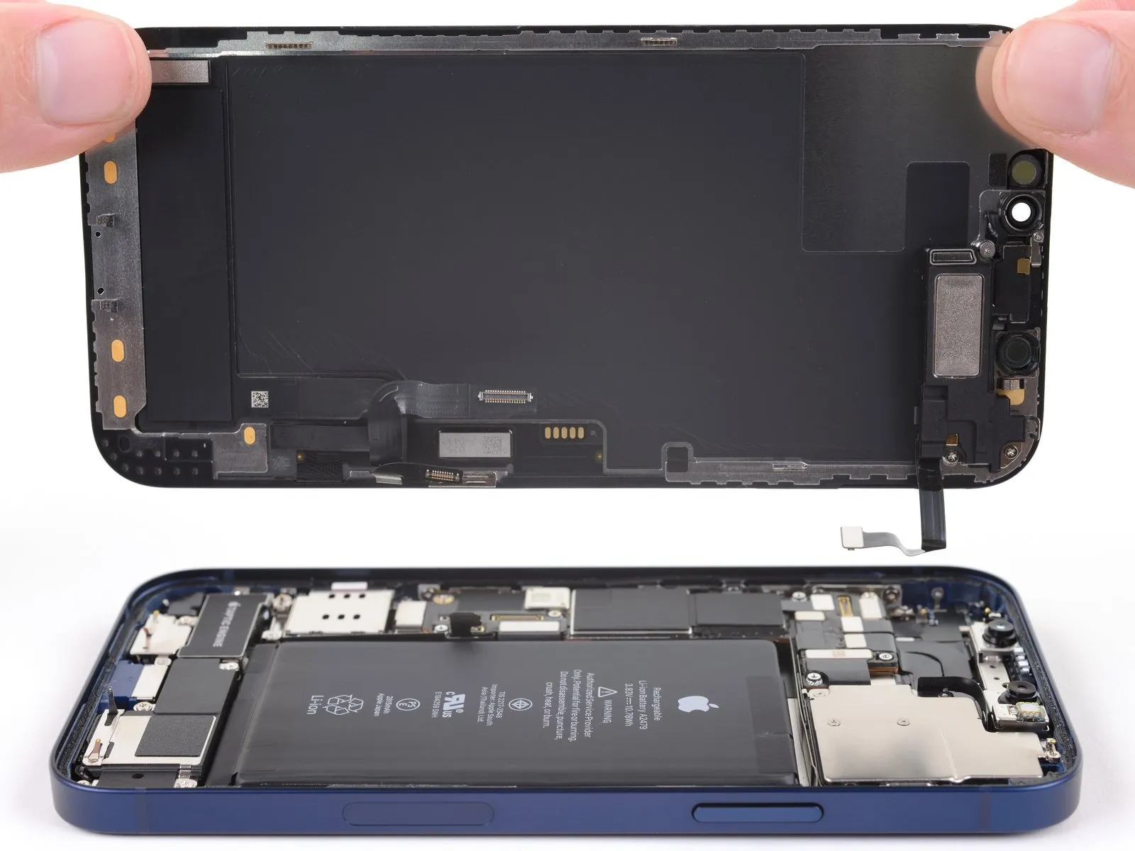
- Detach the display unit from the device.
- If a replacement of the waterproof adhesive sealant bordering the display is desired, halt the reassembly process at this stage.
Step 27 | Unscrew the front-facing camera assembly

Step 28 | Remove the front-facing camera bracket

Step 29 | Disconnect the front-facing camera assembly


Step 30


Step 31


- Carefully move the Face ID cable connectors, separating them from the logic board's surface.This action provides access to the selfie camera connector located directly below.
- Release the selfie camera's connection by applying upward force to its connector, ensuring a straight disconnection.The disconnection should be performed without any lateral movement to prevent damage.
Step 32 | Remove the front-facing camera assembly
