iPhone 13 Taptic Engine Replacement
The iPhone 13's vibrational sensations and responsive tactile feedback are generated by the Taptic Engine component.This repair documentation details the procedure for detaching and substituting the Taptic Engine.Successful completion of this process requires careful adherence to the provided steps to avoid damage.The Taptic Engine is a delicate component, necessitating meticulous handling during removal and reinstallation.Refer to the subsequent instructions to properly replace the Taptic Engine within the iPhone 13's internal assembly.
Step 1 | Remove the pentalobe screws
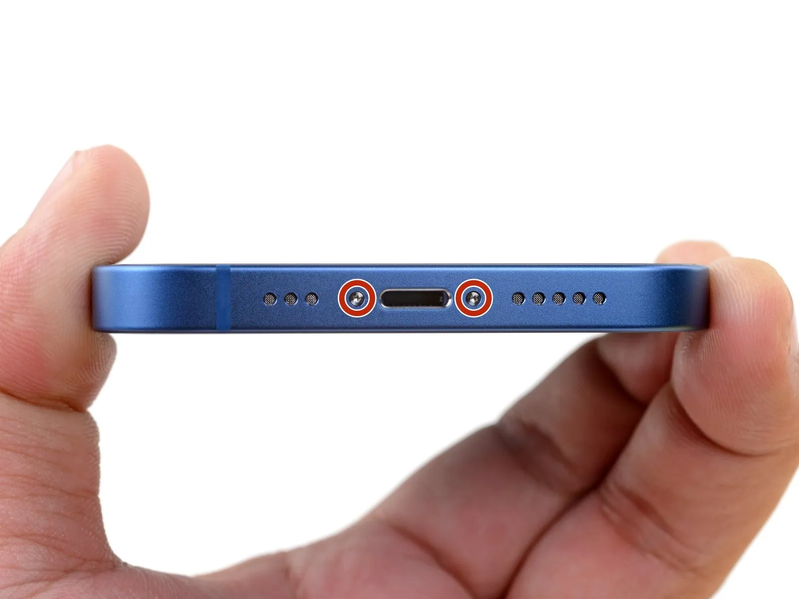
- Deactivate the iPhone's power supply to prevent electrical shorts during the disassembly process.
- The two screws securing the bottom edge, each measuring 6.8 mm in length and utilizing a pentalobe P2 head, must be removed.
Step 2 | Mark your opening picks


- Employing a permanent marker, indicate a point precisely 3 millimeters from the tool's distal end.
- For enhanced precision, consider marking the tool's other corners with varying measurements to suit different tasks.
- As an alternative method, affix a coin to the tool's tip using adhesive tape, positioning it 3 millimeters from the end.
Step 3 | Tape over any cracks


- Apply successive layers of transparent packing tape across the iPhone's screen surface, ensuring complete coverage of the face.
- Should the suction cup fail to maintain adhesion during subsequent procedures, construct a handle from a robust adhesive tape, like duct tape, and employ it to elevate the screen.
- As a last resort, secure the suction cup to the display using superglue.
Step 4 | Anti-Clamp instructions


- To disengage the Anti-Clamp's gripping mechanism, retract the blue handle towards the rear.
- Position the tool's arms across either the left or right side of the iPhone's casing.
- Secure the suction cups close to the lower boundary of the iPhone, placing one on the display side and one on the rear casing.
- Apply the necessary adhesion by compressing the cups together, ensuring a firm grip on the intended surface.
- Should the iPhone's exterior exhibit excessive slipperiness, hindering the Anti-Clamp's ability to maintain contact, applying adhesive tape can enhance surface friction.
Step 5


- Rotate the handle a full 360-degree circle, or continue until the suction cups exhibit signs of deformation.
Step 6


- To facilitate subsequent procedures, stabilize the iPhone on a firm surface, like a hardback book, ensuring it remains level and free from your hands.
- Employ a hair dryer to apply heat along the iPhone's lower edge, achieving a temperature just beyond comfortable touch.
- Refer to a dedicated guide for detailed instructions regarding the safe and effective operation of a hair dryer.
- Allow a sixty-second interval to permit the adhesive to loosen and create a discernible separation.
- Once a noticeable gap appears, carefully slide an opening pick beneath the screen's plastic border.
- Should the Anti-Clamp fail to generate an adequate separation, increase heat application to the area and incrementally rotate the handle by ninety degrees.
- Avoid excessive handle rotation, restricting adjustments to ninety-degree increments, and observe a sixty-second pause between rotations, allowing the Anti-Clamp and time to facilitate the separation.
Step 7 | Heat the bottom edge

- Apply warmth to the iPhone’s lower border using a hair dryer or heat gun, ensuring the screen’s temperature reaches a point where it is noticeably warm but still tolerable to the touch.
Step 8 | Apply a suction cup
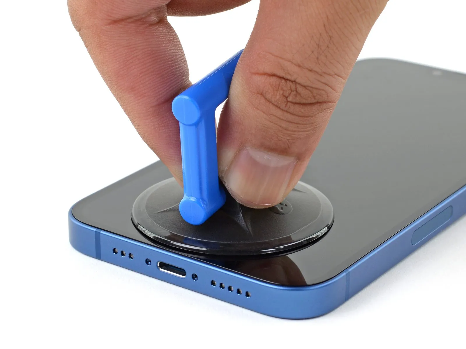
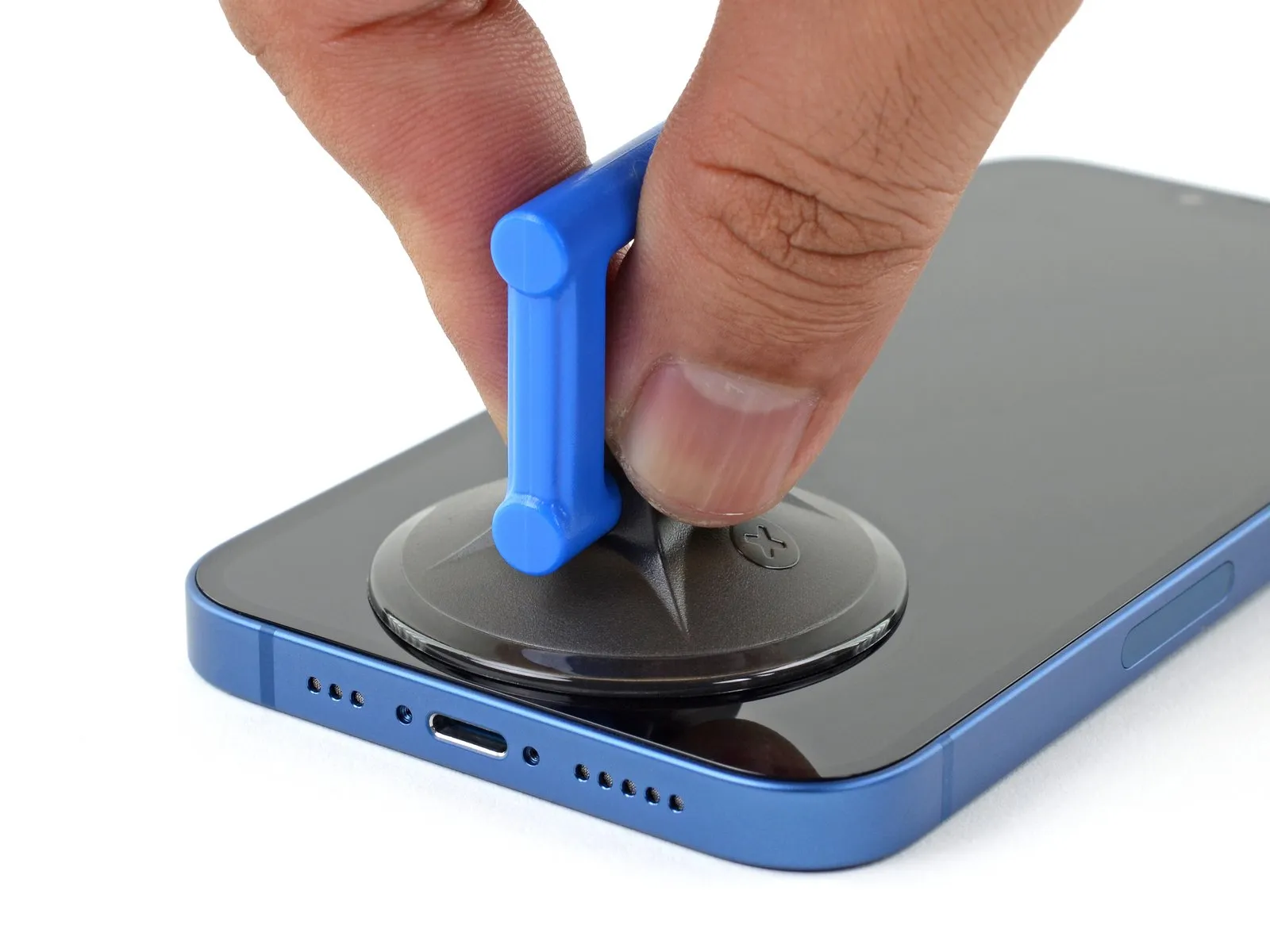
- When employing a solitary suction handle, position it against the lower perimeter of the device's frame, ensuring it remains clear of the outermost glass boundary.
Step 9 | Lift the screen slightly
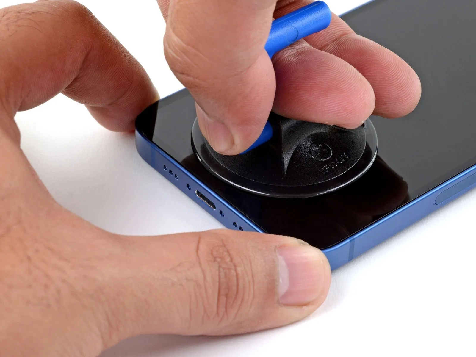
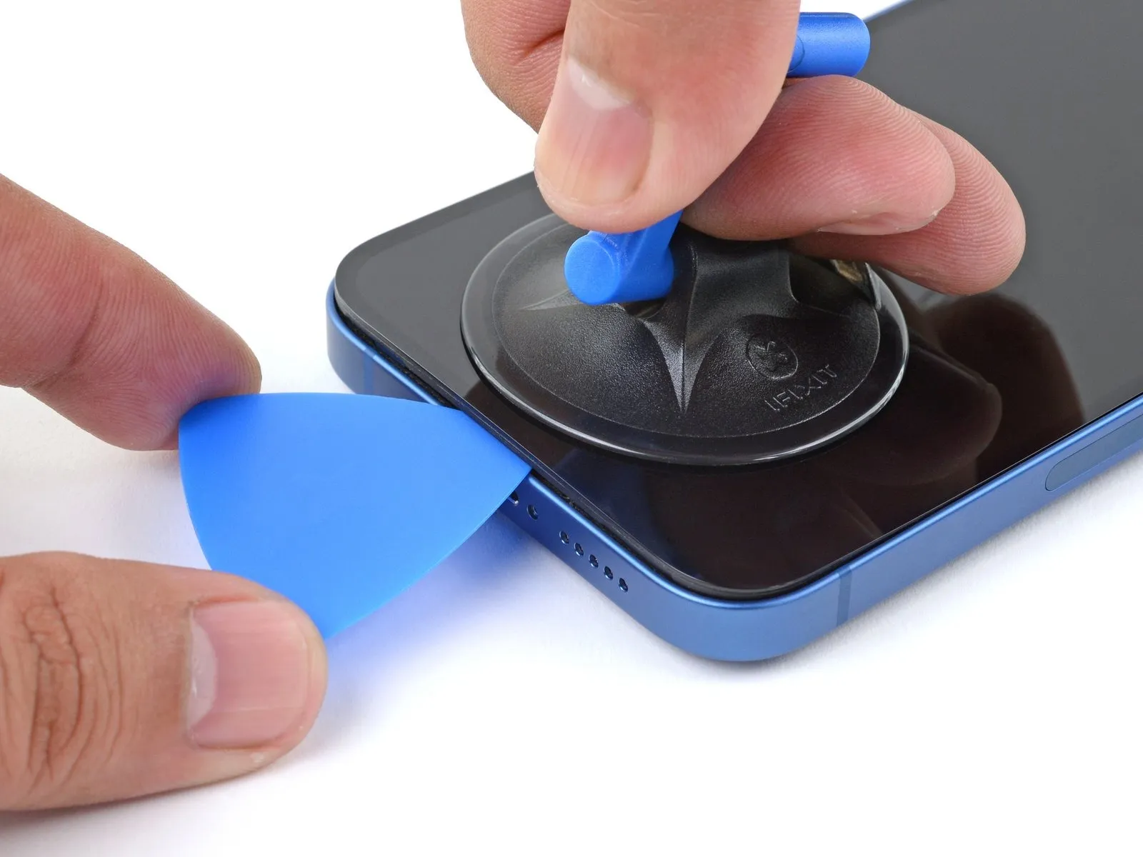
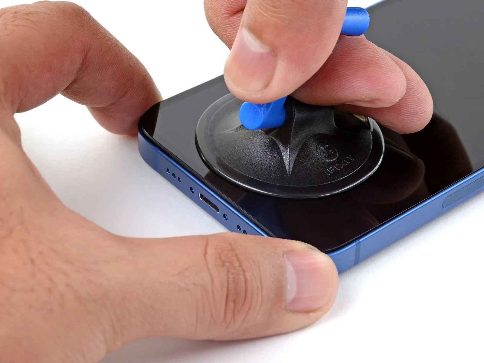
- Maintain consistent, substantial upward force on the suction cup to generate a minimal separation between the display assembly and the device's perimeter.
- Carefully slide a specialized opening tool into the space formed beneath the screen's surrounding plastic trim.
- Due to the robust nature of the waterproof sealant securing the display, a considerable amount of force may be necessary to initially establish this separation; if difficulty arises, apply additional heat and gently oscillate the screen to reduce adhesive strength until a sufficient gap is achieved for tool insertion.
Step 10 | Heat the right edge


To initiate separation, apply warmth to the right-hand side of the iPhone casing, specifically the area bordering the power button, until the surface temperature reaches a level of tactile discomfort.
Step 11 | Separate the right adhesive
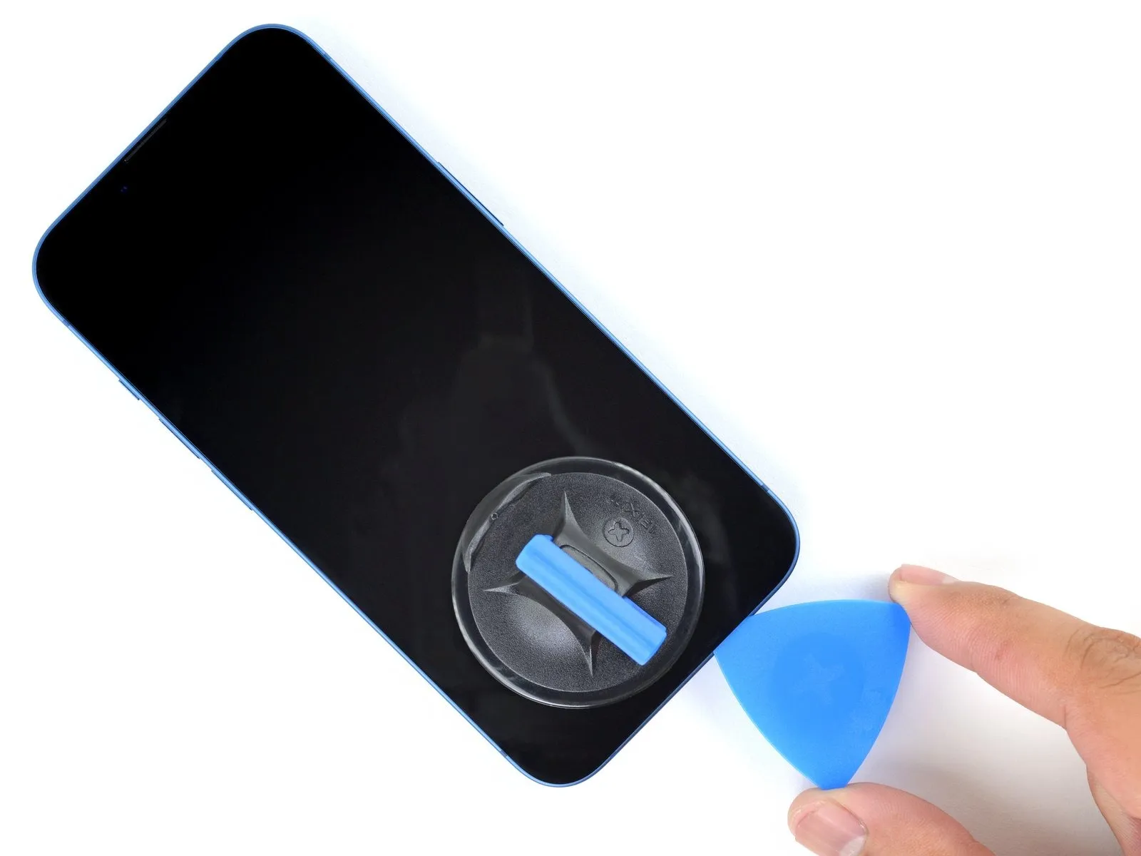
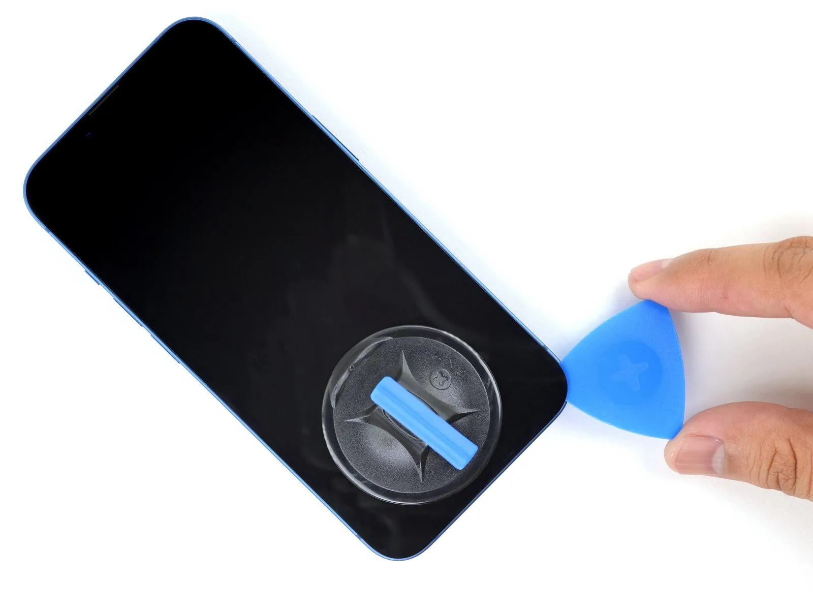
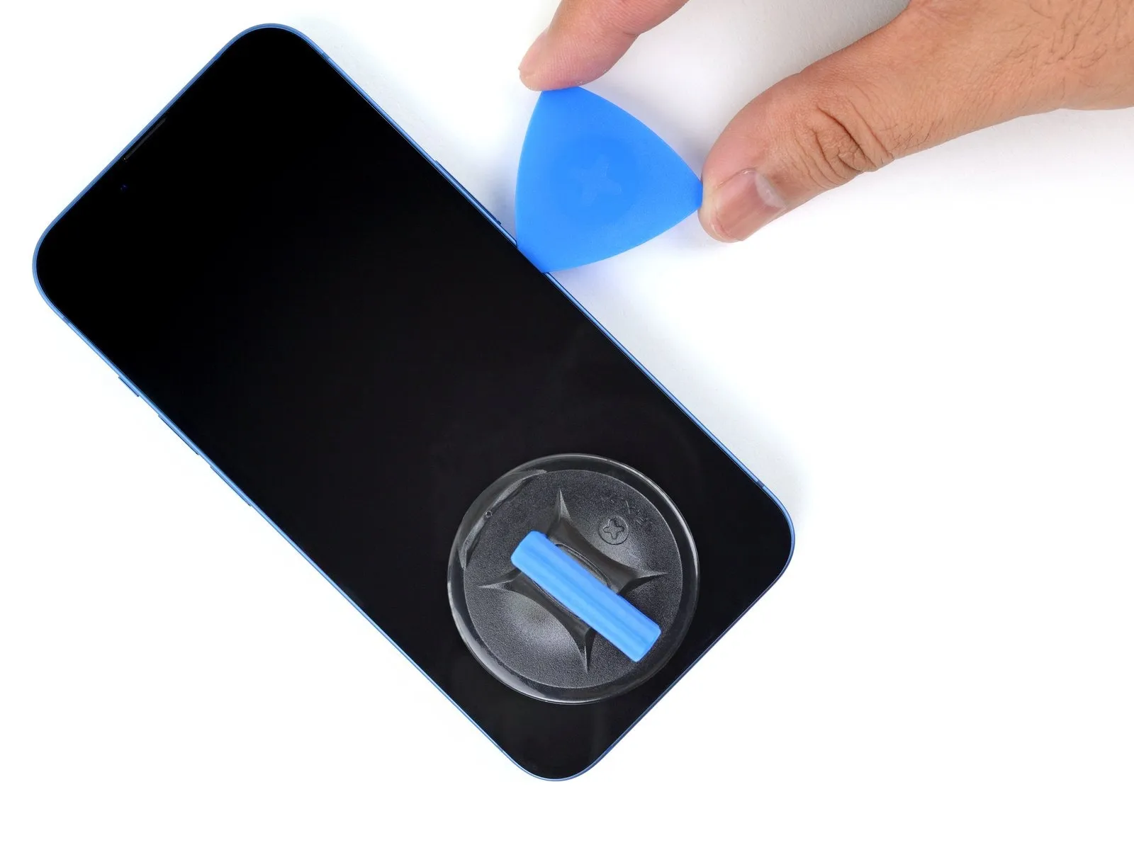
- Progressively move the tool along the right side of the device's exterior, advancing upwards.
- Exercise caution to prevent the tool's insertion depth from exceeding 3 millimeters, mitigating potential harm to the internal electronics.
- Maintain the tool's position at the upper-right corner of the iPhone's enclosure before proceeding with subsequent actions.
- The adhesive securing the iPhone's components should be released by carefully maneuvering the separation tool.
Step 12

The objective of this procedure is to achieve a slightly elevated temperature on the screen's top edge, facilitating separation from the device's frame.
Step 13
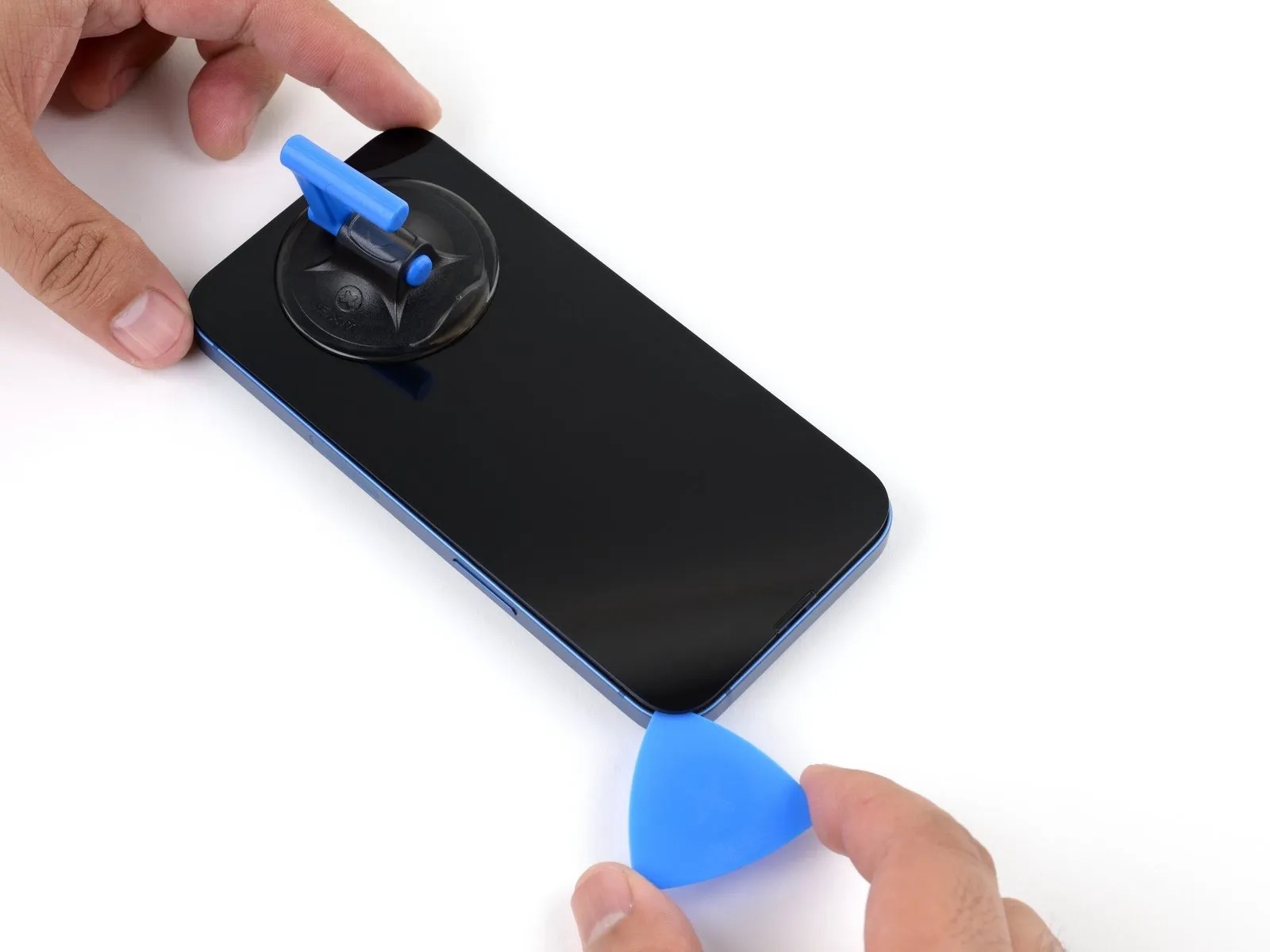
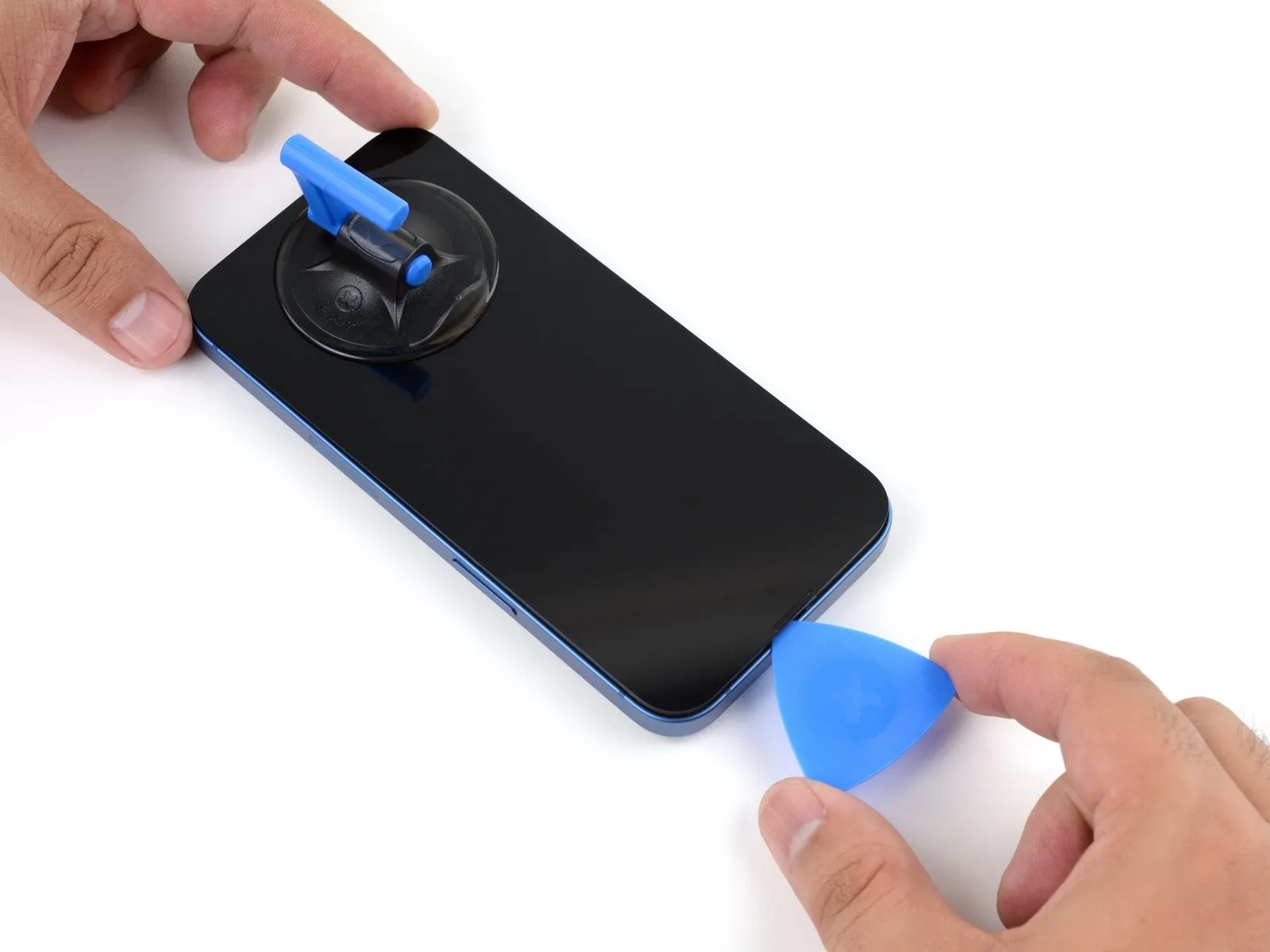
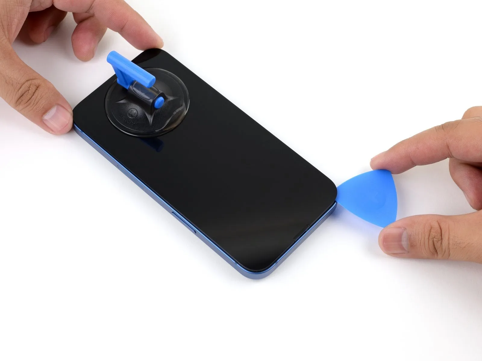
- Utilize a separation tool to detach the adhesive securing the iPhone's upper right edge by gently sliding it into the gap.
- Exercise caution to prevent exceeding a 3 mm insertion depth with the tool, as doing so risks harming the proximity and ambient light sensors.
- Maintain the separation tool's position within the top left corner of the device while advancing to the subsequent procedure.
Step 14 | Heat the left edge


- This localized heating facilitates separation of the display assembly from the chassis, leveraging thermal expansion to overcome adhesive bonding.
Step 15 | Separate the left adhesive
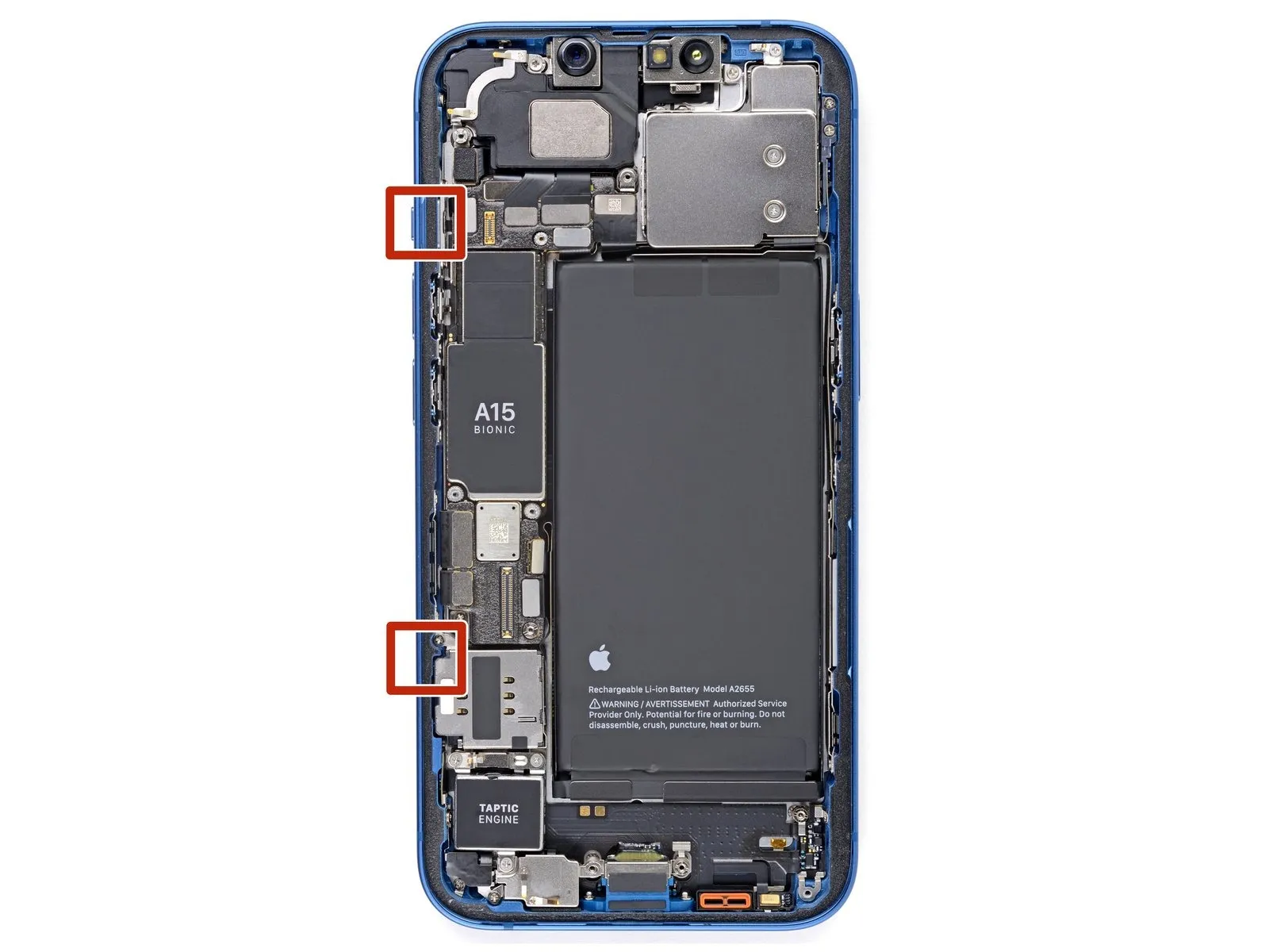


- Exercise caution when working near the sensitive wiring situated along the iPhone's left side; avoid inserting the opening tool beyond a depth of 2 millimeters to prevent potential cable damage.
- Perform a rotational movement with the opening tool around the screen's upper-left quadrant.
- Advance the opening tool along the left edge, reaching the lower corner, to release the adhesive bond.
- Should adhesive separation prove difficult, apply localized heat to the left edge to soften the adhesive.
Step 16 | Open the iPhone
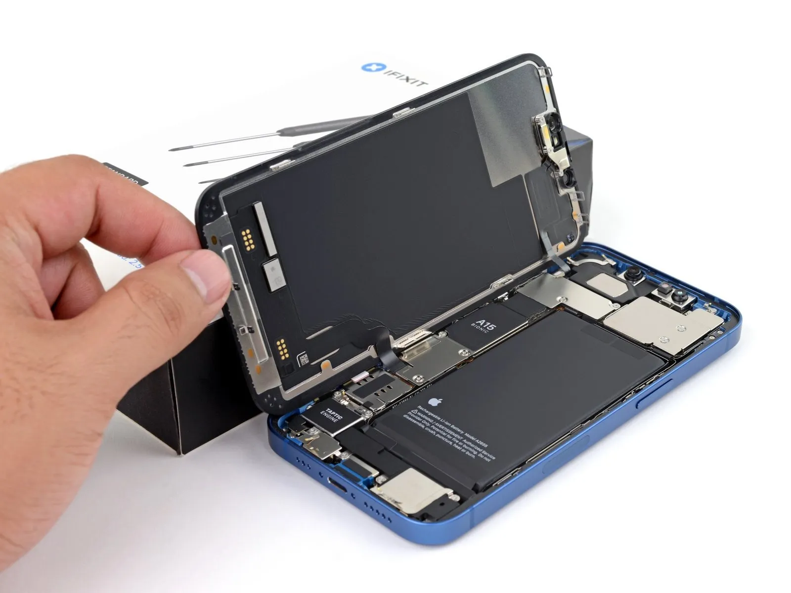
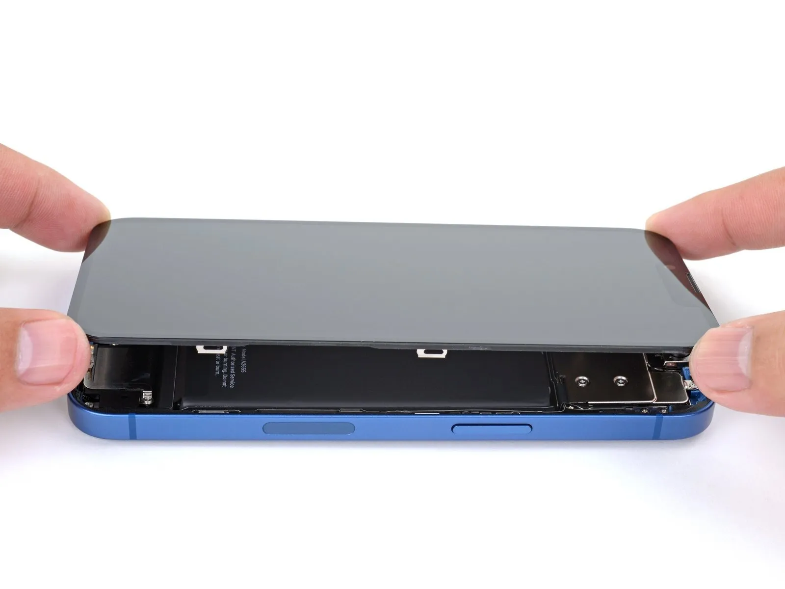
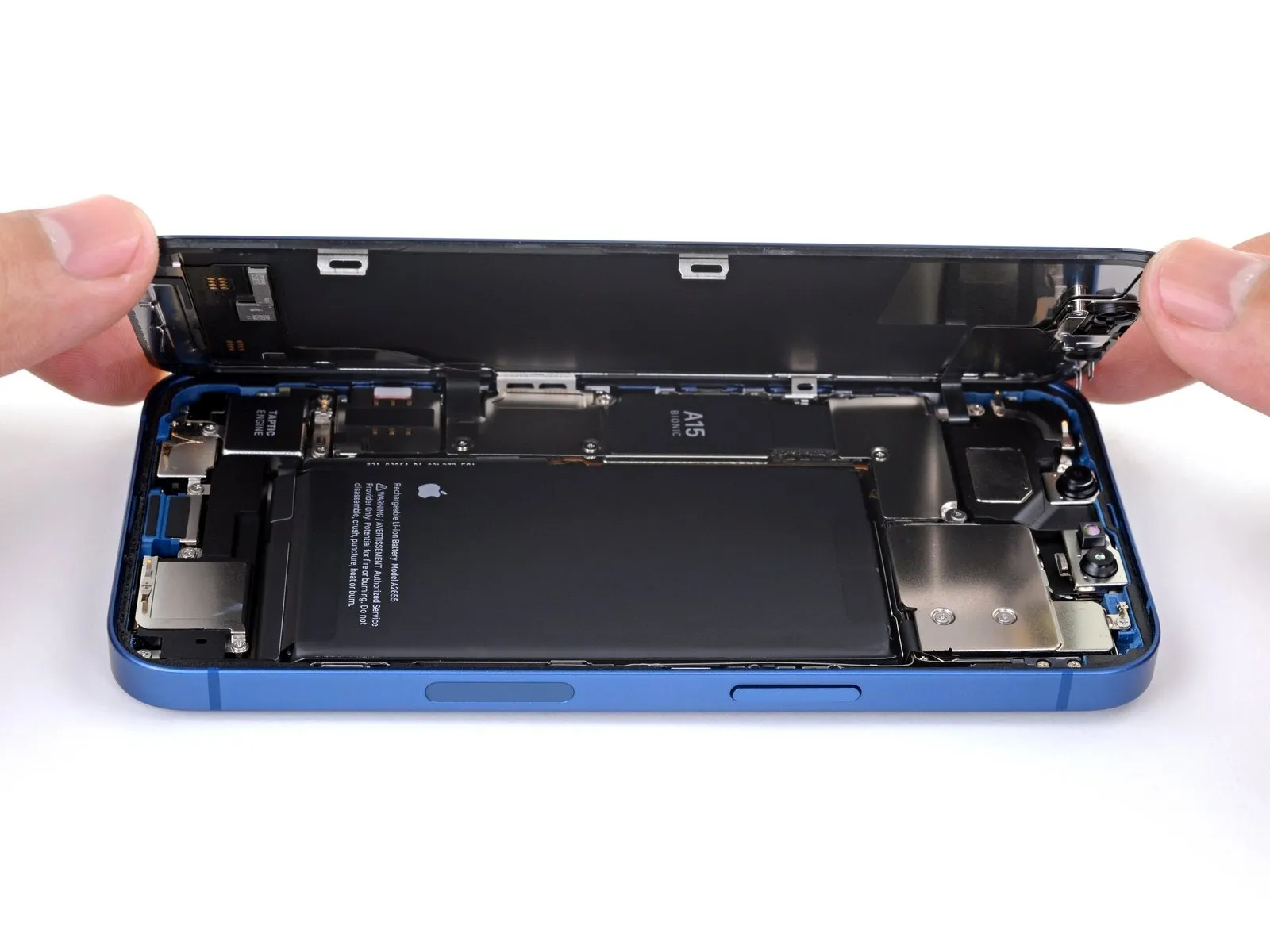
- Prior to proceeding, ensure the suction handle has been detached.
- Orient the iPhone so that its right-hand edge is directed towards you.
- Initiate the display opening process by pivoting the screen upwards from the right side, mimicking the action of opening a book's cover.
- Avoid complete separation of the display at this stage, as delicate ribbon cables remain connected to the internal logic board.
- Secure the display in an upright position using a support to maintain access during the repair process.
- When reassembling, position the display, match the clips along the upper edge, and gently apply pressure to the top edge before securing the remainder of the display; if resistance is encountered, inspect the clips around the display's perimeter for any deformation.
Step 17 | Unscrew the battery and display connector cover
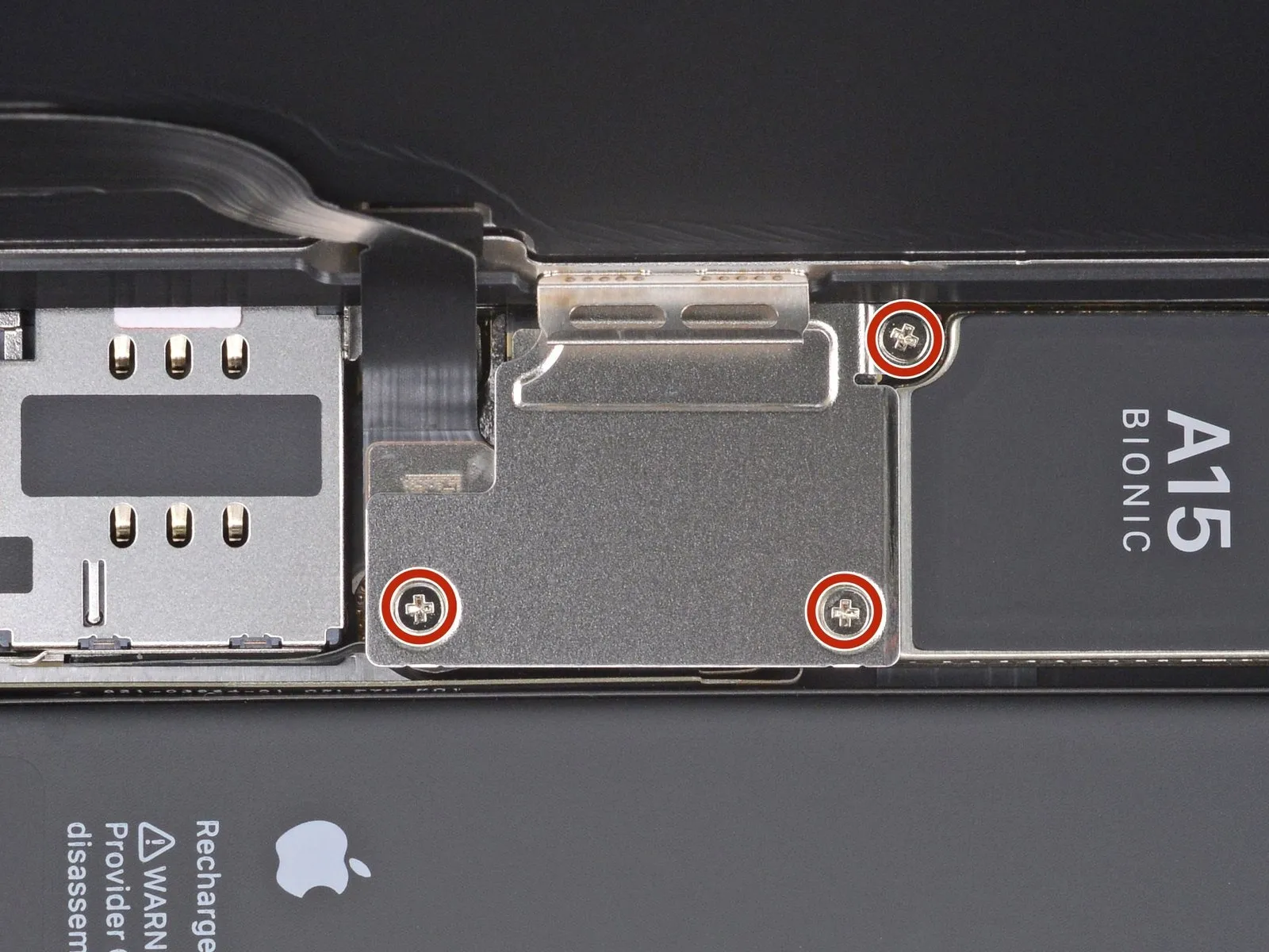
- Employ a Phillips screwdriver to detach the three 1.3 mm screws that hold the battery and display connector cover in place.Carefully monitor the location of each screw during disassembly, ensuring proper placement during reassembly to prevent potential damage to the iPhone.Prior to securing the display, it is advisable to activate the iPhone and verify all operational features.Completely de-energize the iPhone by powering it down before proceeding with the remaining repair steps.The three 1.3 mm screws are responsible for fastening the battery and display connector cover.
- Maintaining accurate screw placement is crucial to avoid inflicting harm to the device's internal components.
- A functional test of the iPhone's features should be performed after reassembly but before the display is permanently affixed.
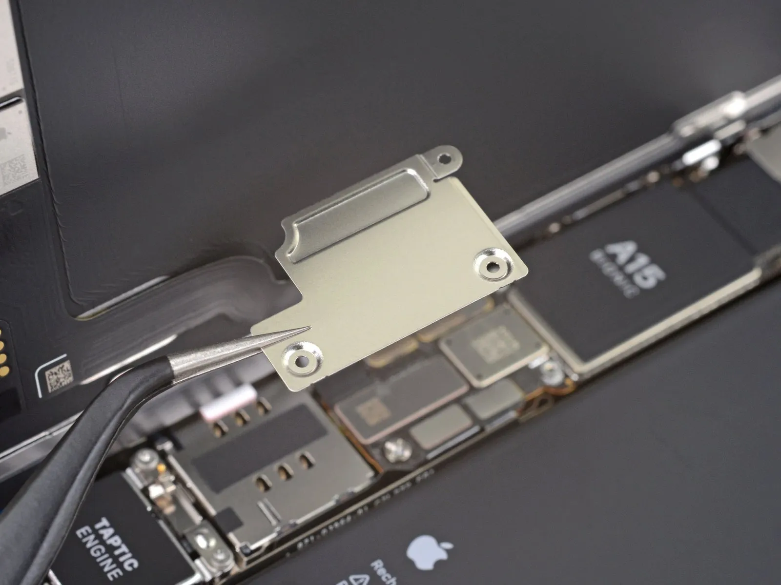
Step 18 | Remove the battery and display connector cover
Step 19 | Disconnect the battery
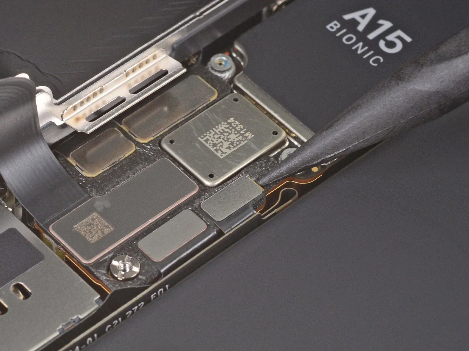
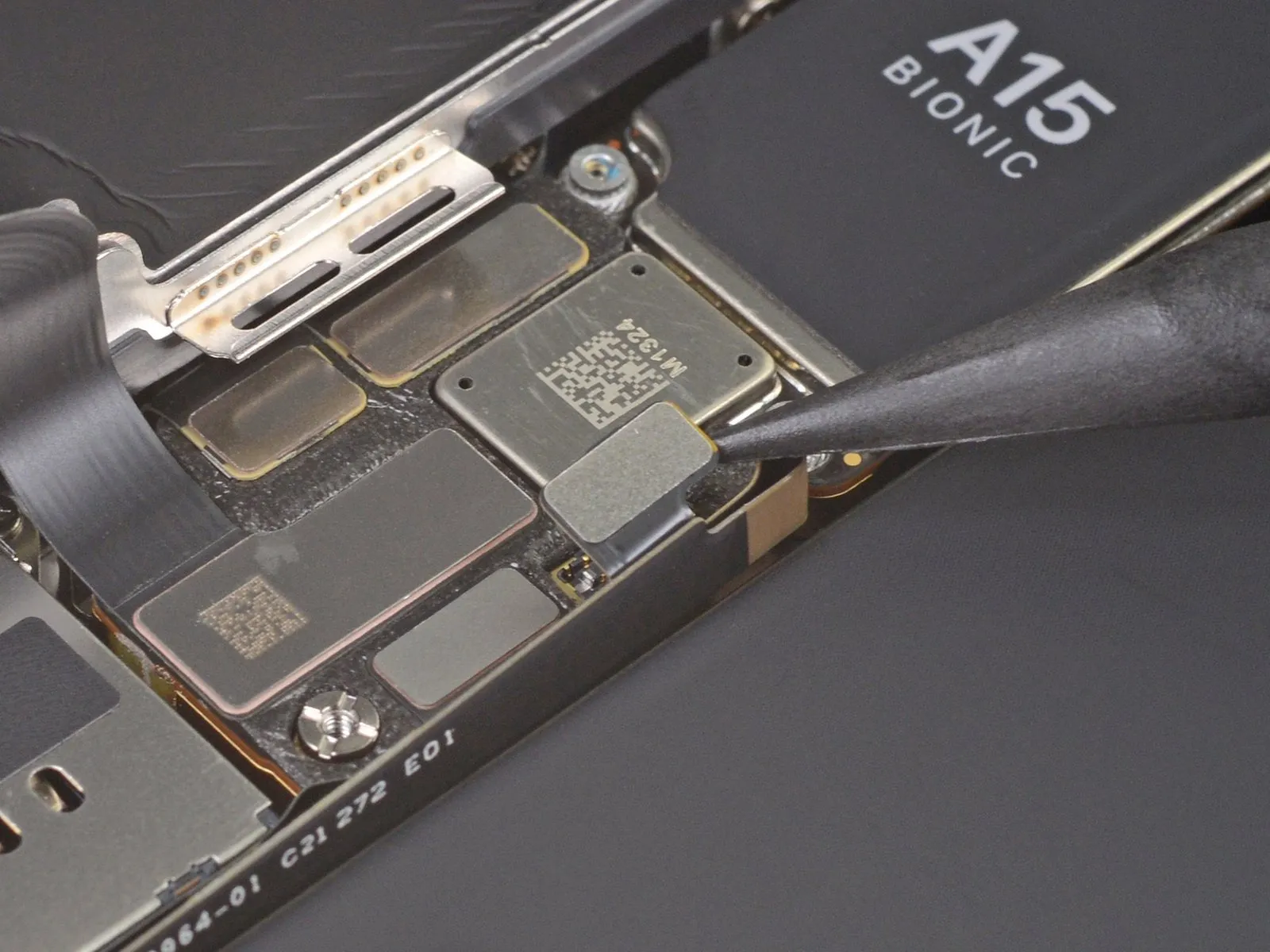
- Employ a spudger tool, or a similarly non-marring implement like a clean fingernail, to lift the battery connector's retaining clip from its corresponding receptacle on the logic board.Exercise caution to avoid harming the black silicone sealant that encapsulates this connector and others, as it is crucial for safeguarding against ingress of water and particulate matter.To preclude unintended power delivery to the device during the repair process, slightly deflect the connector away from the logic board’s surface.
- The silicone seals offer an additional layer of protection against environmental contaminants, therefore their integrity must be maintained.
- Careful manipulation of the battery connector is necessary to prevent accidental contact and potential short circuits while performing the repair.
Step 20 | Disconnect the display cable
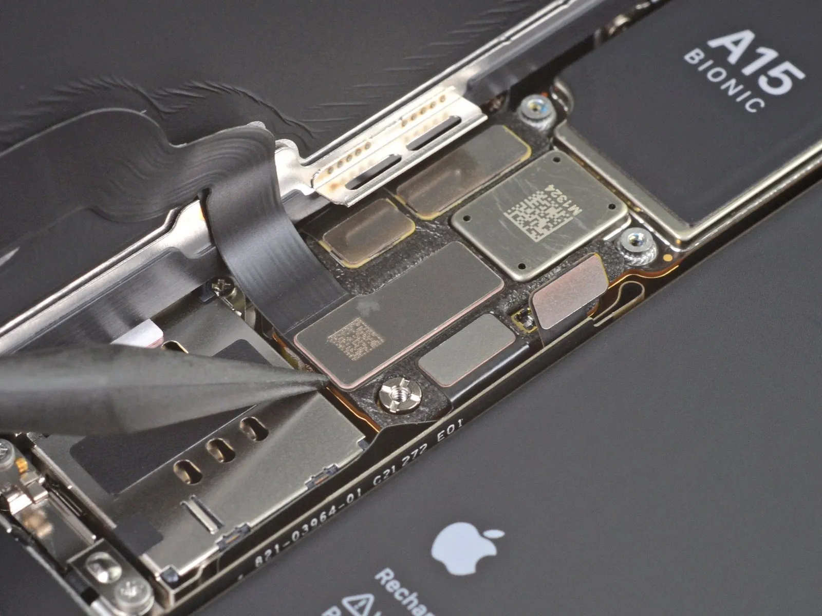
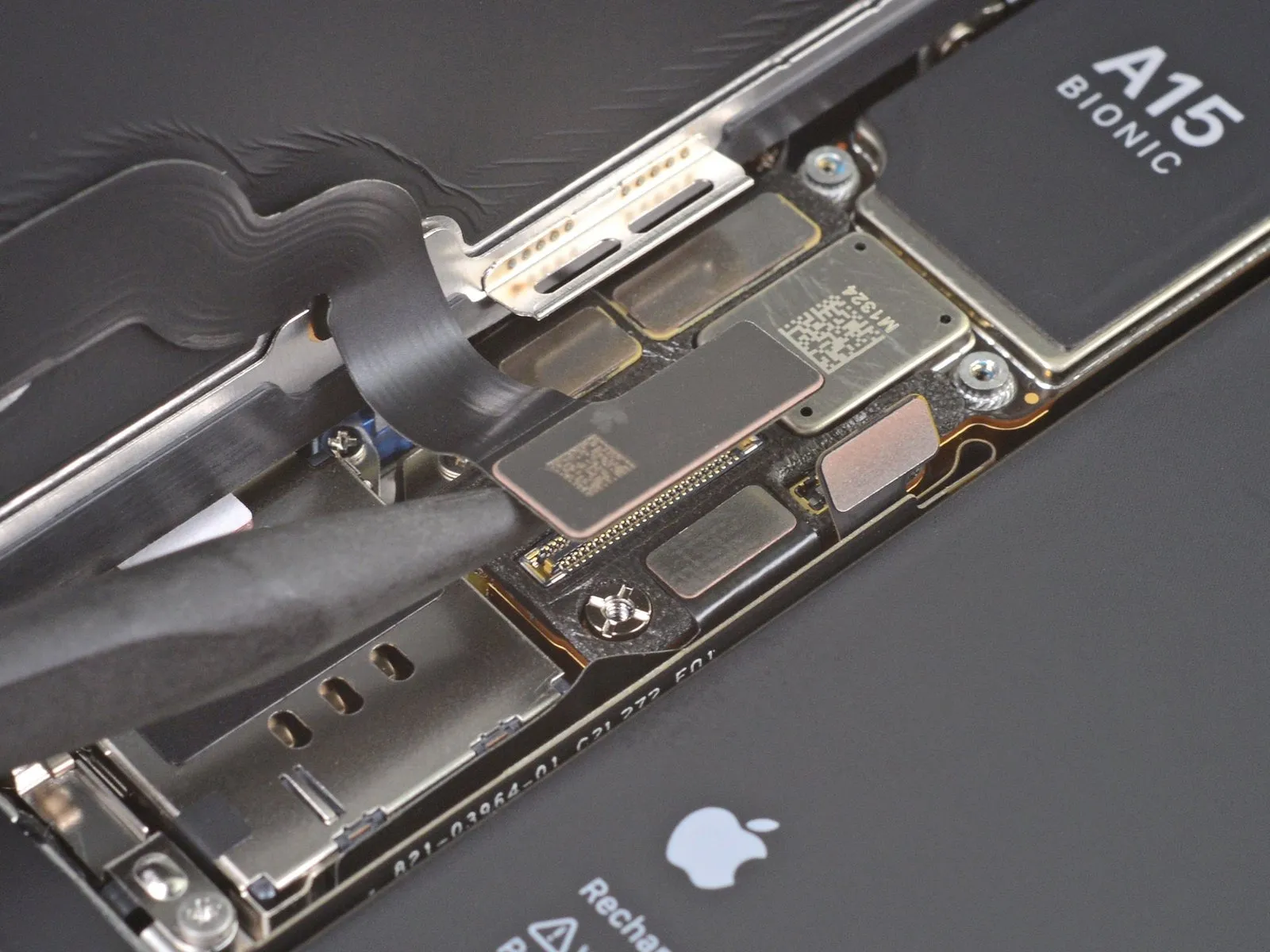
- Employing a spudger or fingernail, carefully separate the display cable connector.For reattachment, align the connectors meticulously, applying pressure to one edge until a click is heard, and then repeating the process on the opposing edge.Avoid applying pressure to the central portion of the connector during reattachment.
- Misalignment of the connector can result in pin deformation, potentially leading to irreversible component failure.
Step 21 | Unscrew the front sensor connector cover
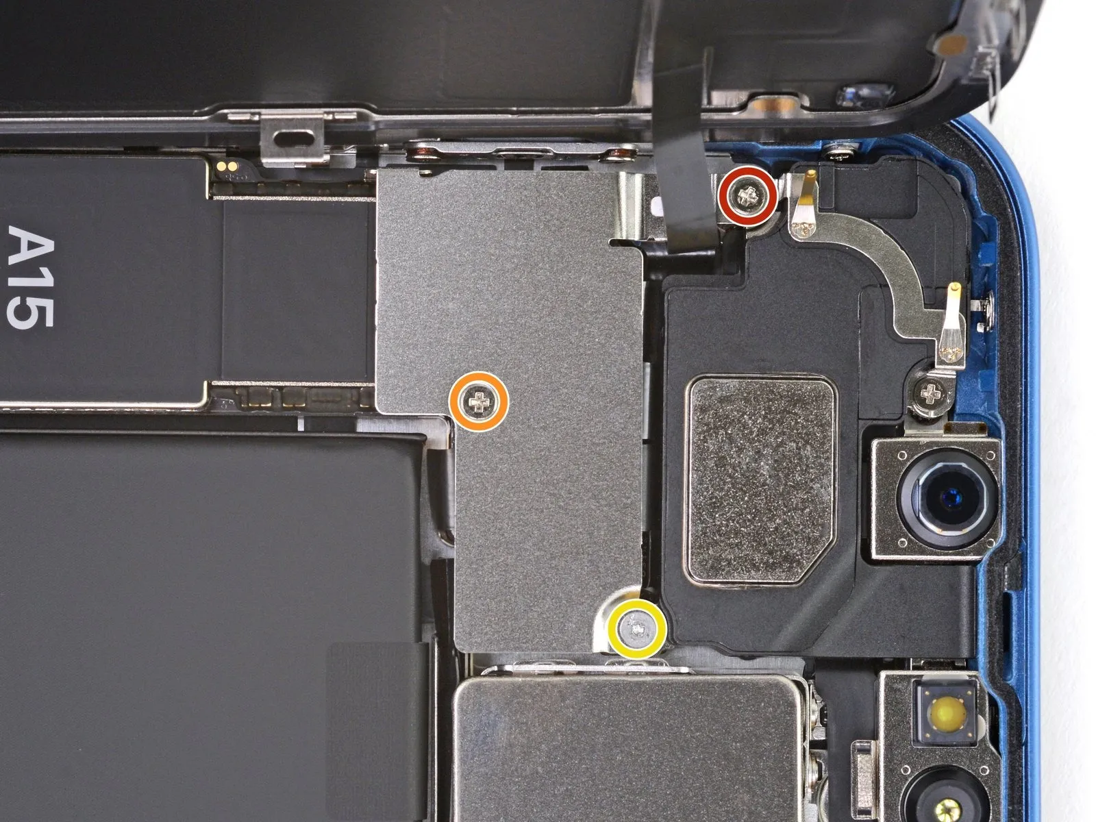
- To access the front sensor connector, detach the cover using three screws.
- A 1.7-millimeter Phillips head screwdriver is required for one of the screws.
- A 1.3-millimeter Phillips head screwdriver is necessary for another screw.
- A Y000 screwdriver, measuring 1.8 millimeters, is needed for the final screw.
Step 22 | Remove the front sensor connector cover
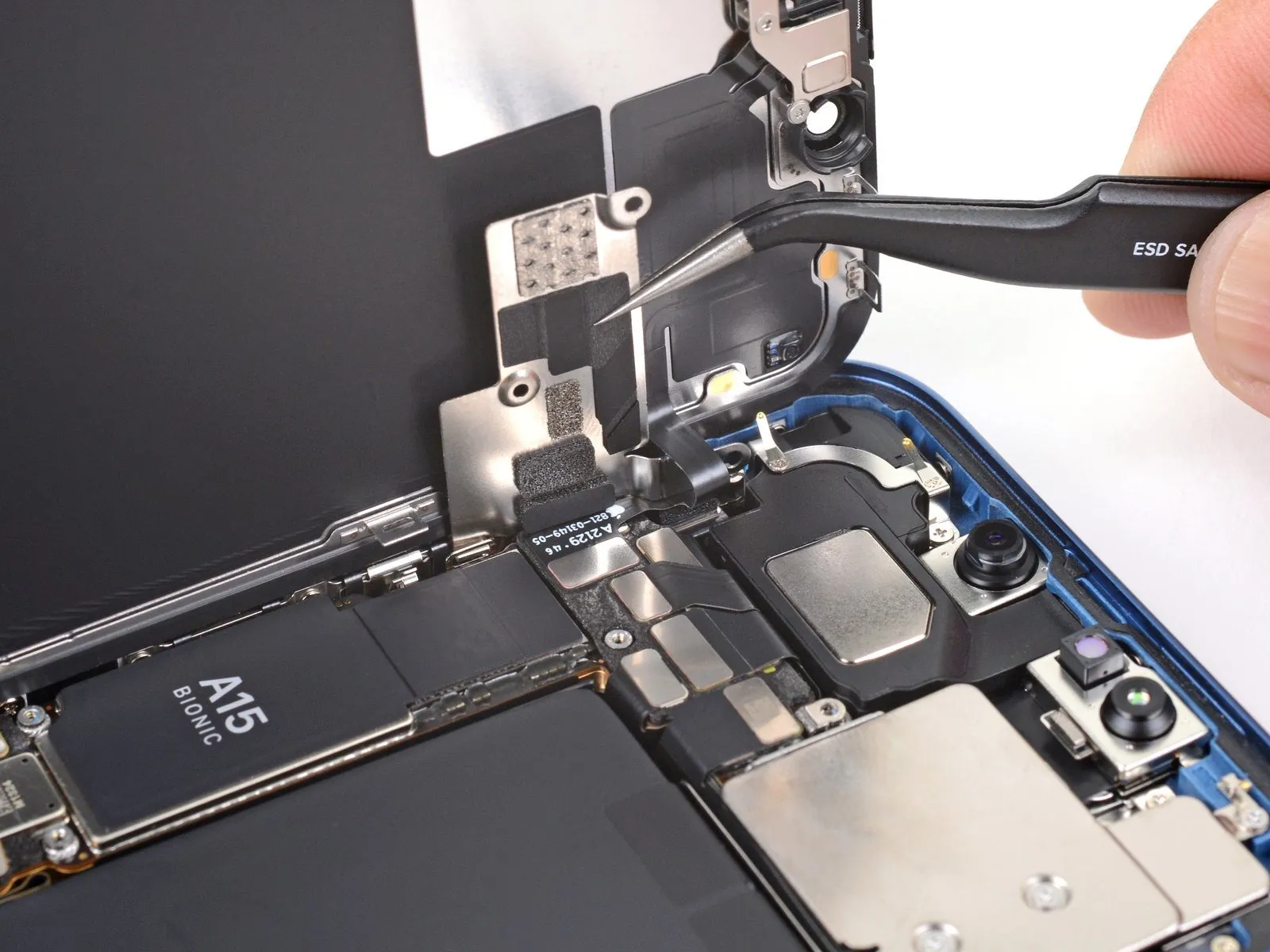
Step 23
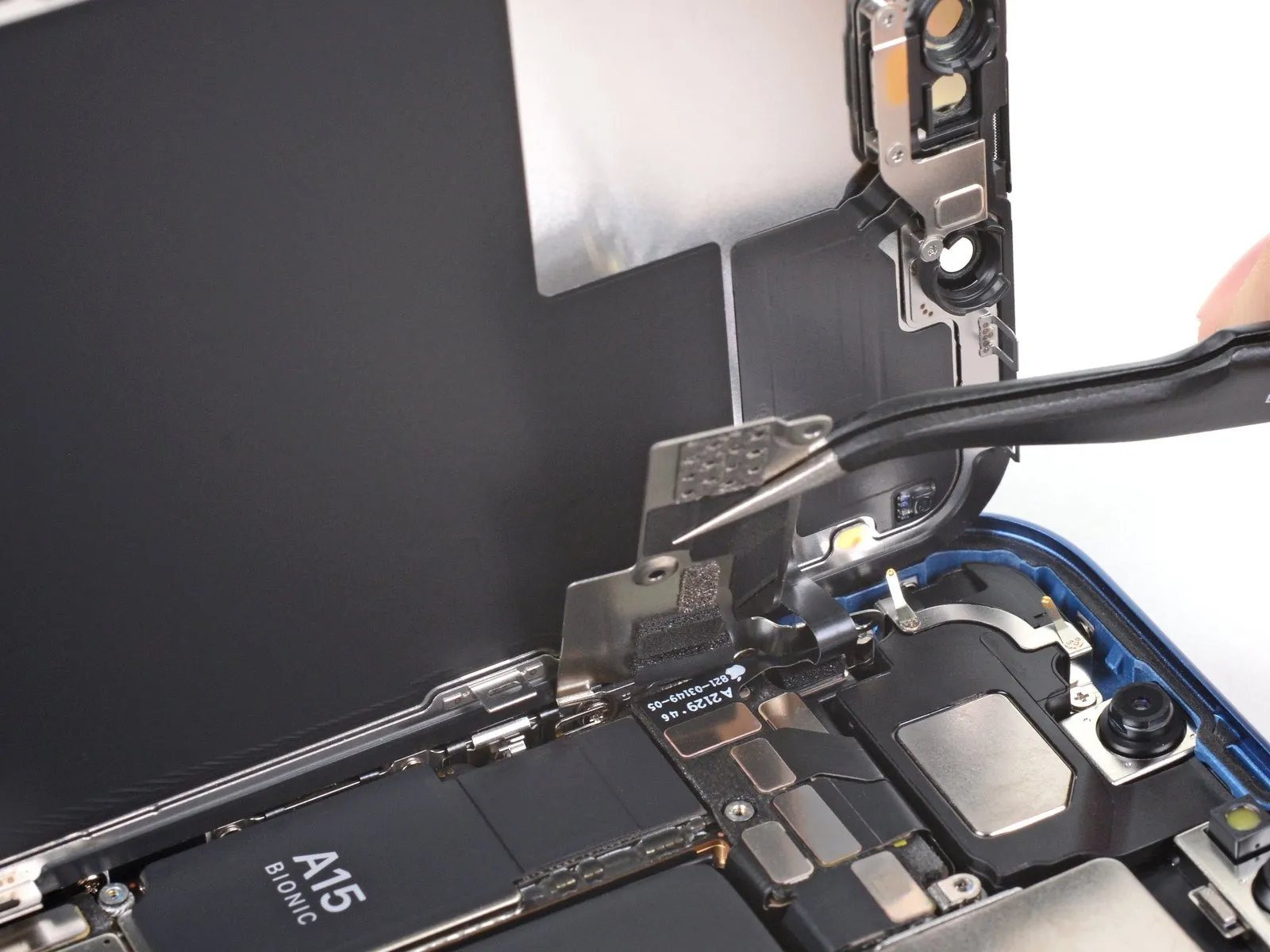
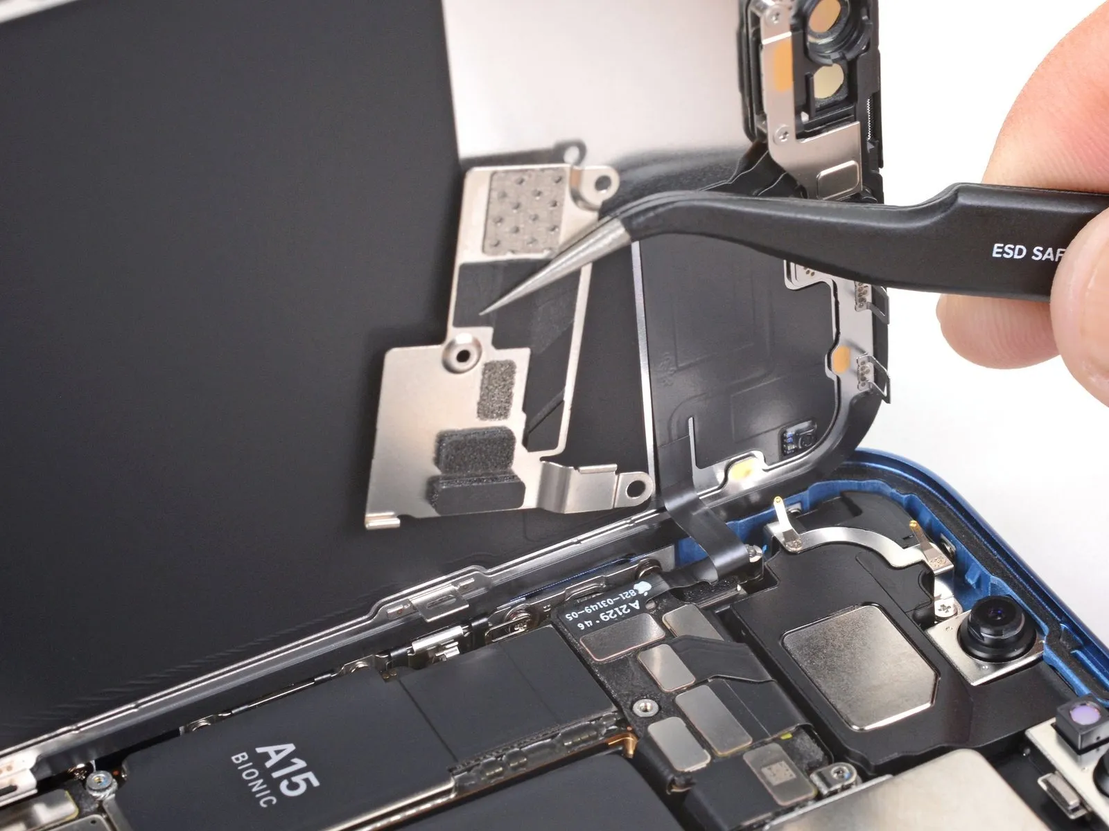
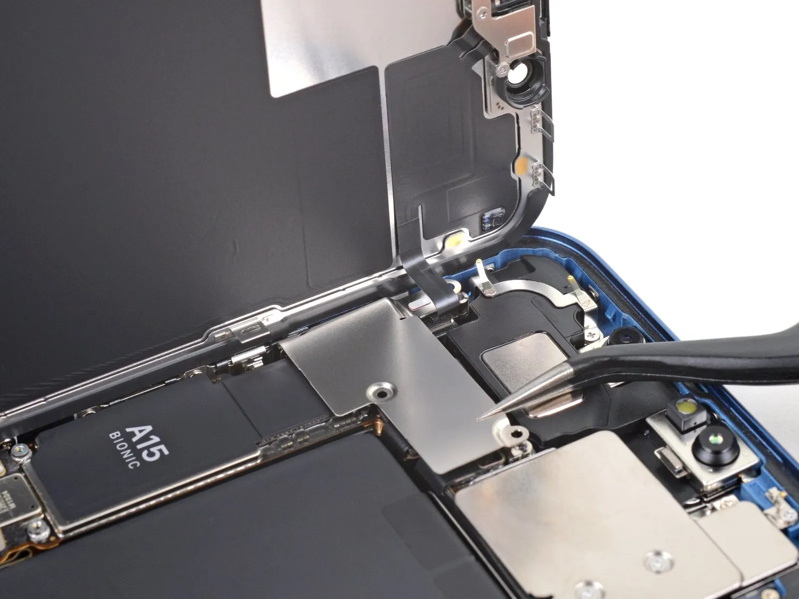
- Detach the protective housing.
- To reattach the cover, initially position the clip located on the left side within its corresponding receptacle, subsequently pivoting the remaining portion of the cover to secure it.
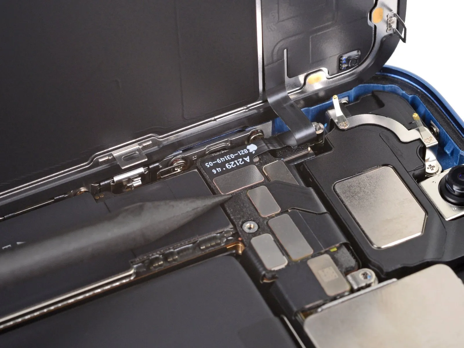
Step 24 | Disconnect the front sensors
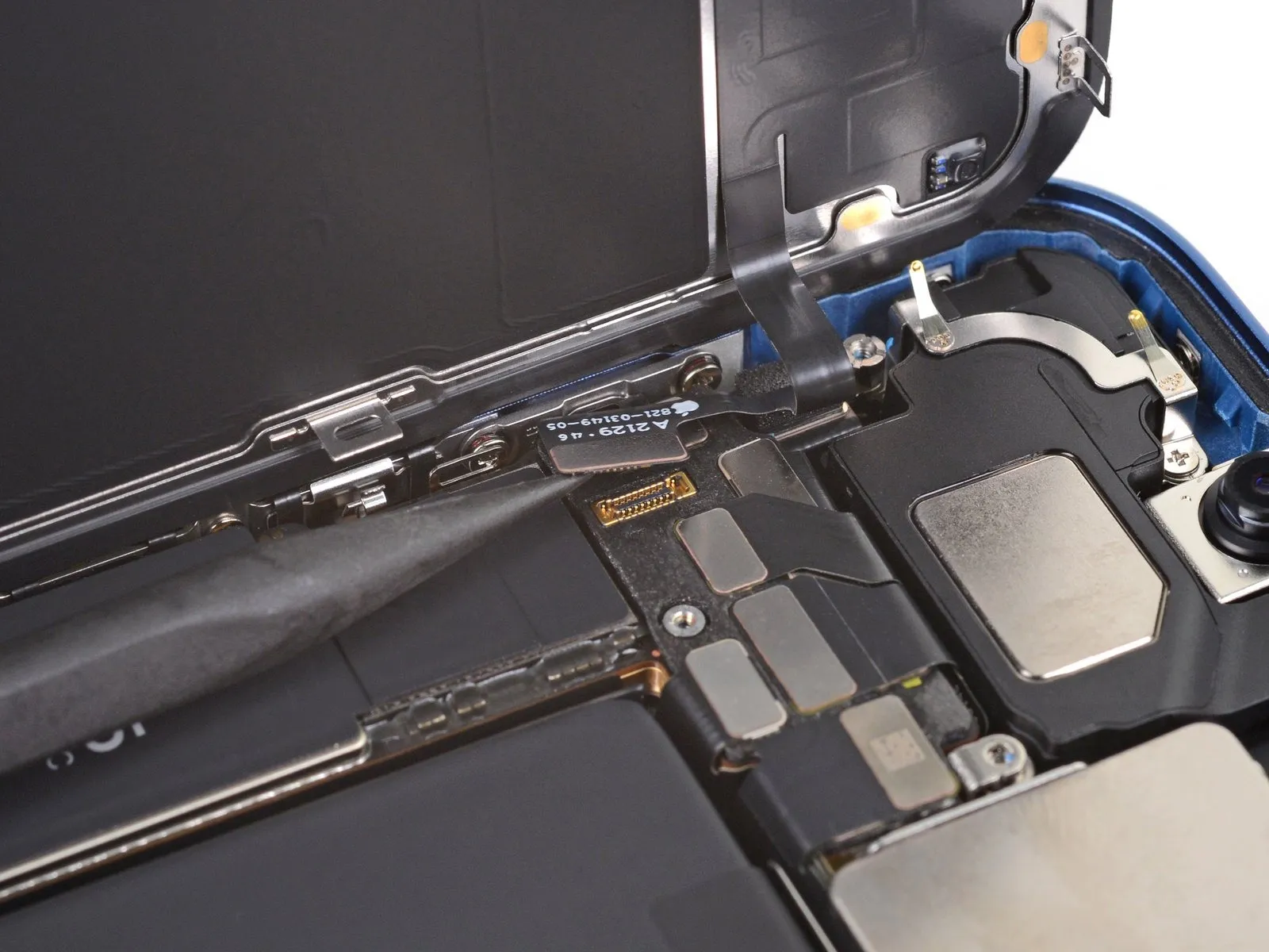
Step 25 | Remove the screen
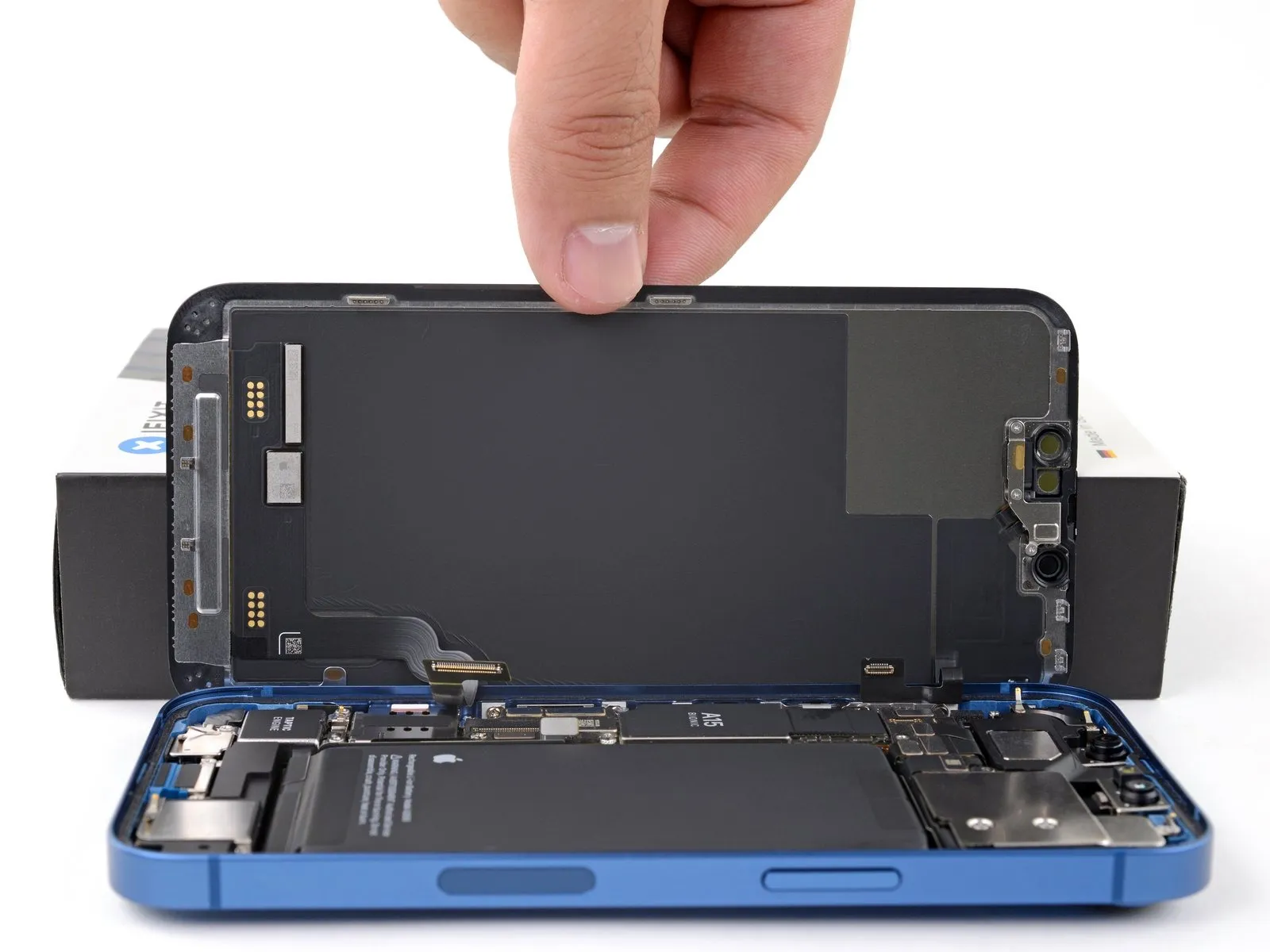
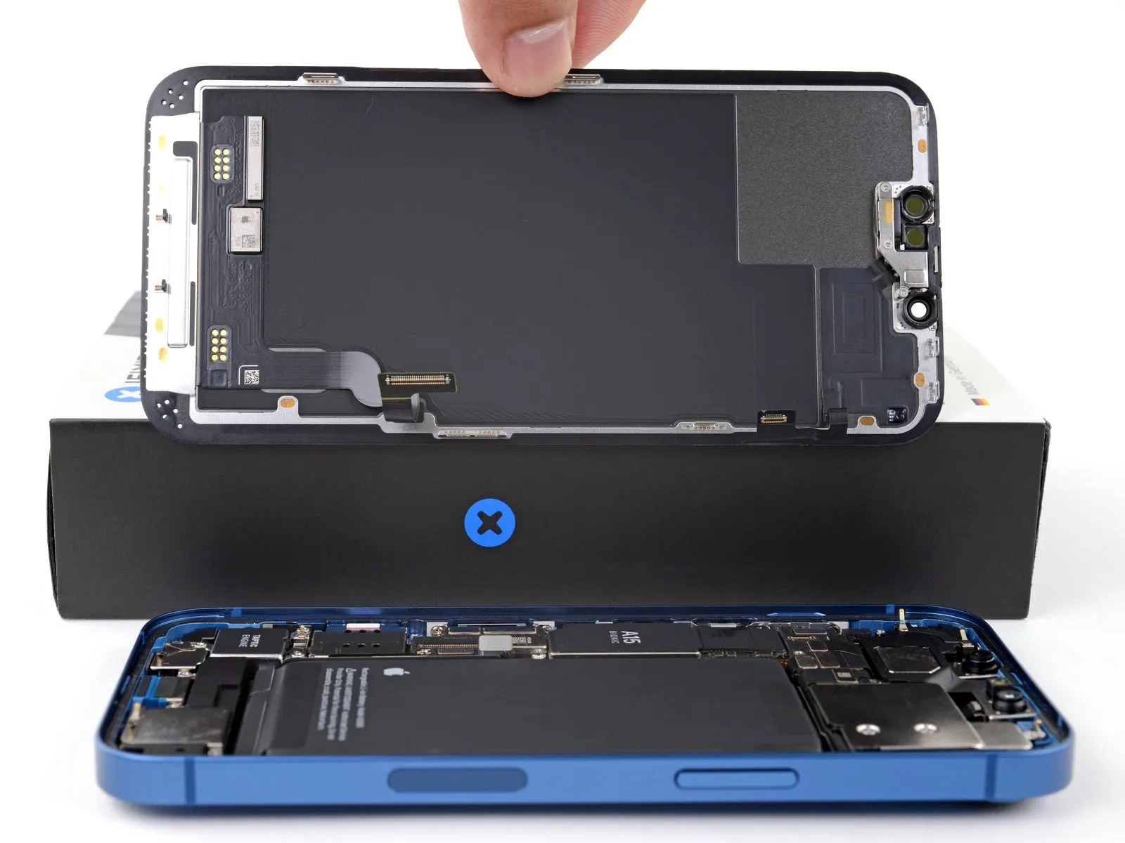
- Detach the display panel from the device.
- If a replacement of the water-resistant adhesive strip situated along the display's perimeter is desired, halt the reassembly process at this juncture.
Step 26 | Unscrew the Taptic Engine

Step 27 | Remove the Taptic Engine bracket

Step 28 | Reposition the Taptic Engine


- To dislodge the Taptic Engine, elevate it by its bottom edge, positioning it inverted upon the SIM card reader.
- Exercise caution to prevent damage to the fragile ribbon cable that links the Taptic Engine to the main circuit board; avoid applying pulling or rotational force during the repositioning process.
Step 29 | Disconnect the Taptic Engine


Step 30 | Remove the Taptic Engine

Step 31 | Reassembly information


- To reassemble the device, adhere to the subsequent instructions for the Taptic Engine connection.The Taptic Engine must be positioned inverted on the SIM card reader.Ensure the Taptic Engine’s ribbon cable aligns with the corresponding connector on the logic board during placement.
- Employ the planar extremity of a spudger tool, or a fingertip, to reattach the Taptic Engine press connector.The Taptic Engine press connector requires secure reconnection to facilitate proper function.After connecting the ribbon cable, rotate the Taptic Engine to its original orientation.The Taptic Engine should be flipped back into its designated recess within the device.Proper alignment of the ribbon cable is crucial for successful reconnection.
- Utilize a spudger or fingertip to apply gentle pressure during connector engagement.The SIM card reader serves as a temporary support during the reconnection process.Inverting the Taptic Engine allows for easier access to the ribbon cable connector.Carefully maneuver the component to avoid damaging surrounding components.The press connector secures the ribbon cable to the logic board.
- A secure connection of the Taptic Engine press connector is essential for device operation.Following these steps ensures correct Taptic Engine installation and functionality.The recess provides a stable mounting point for the Taptic Engine.