iPhone 13 Pro Motherboard Separation
Prior to commencing any repair work, disconnect the device entirely from all electrical power connections to guarantee safety.
- The following implements are necessary to complete the repair:A Phillips head screwdriver is needed for disassembly and reassembly.
Should difficulties arise while performing the repair, refer to the official manufacturer's instructions or obtain help from a qualified technician.
Step 1 | Overview
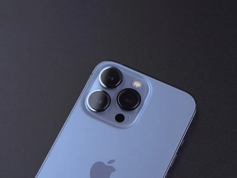

- The preceding article detailed the disassembly of an iPhone 13 Pro; this guide will demonstrate the motherboard separation process for comparative analysis of design variations and repair complexity.
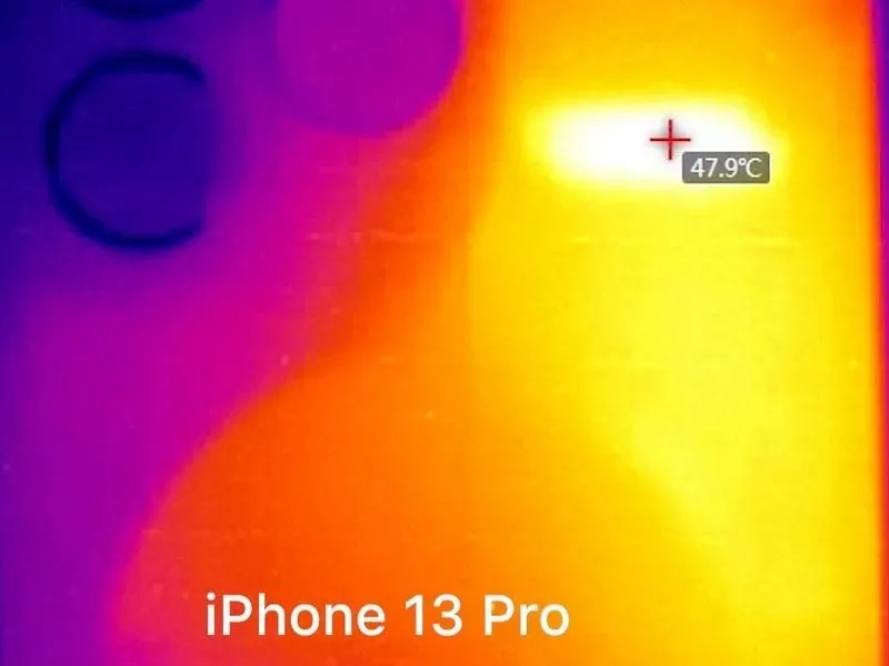
- Utilizing a LINCSEEK Infrared Thermal Camera, observations reveal elevated operating temperatures in the iPhone 13 Pro.The device under examination is an iPhone 13 Pro.The iPhone 13 Pro exhibits a higher thermal output compared to its predecessor.Peak temperatures on the iPhone 13 Pro approximate 48 degrees Celsius.The iPhone 12 Pro's maximum operating temperature is approximately 40 degrees Celsius.A noticeable temperature difference exists between the two iPhone models.This thermal disparity suggests potential design or component differences.Careful handling is crucial during motherboard separation to prevent damage.The observed temperature increase may be attributable to enhanced processing capabilities or altered thermal management.
Step 2
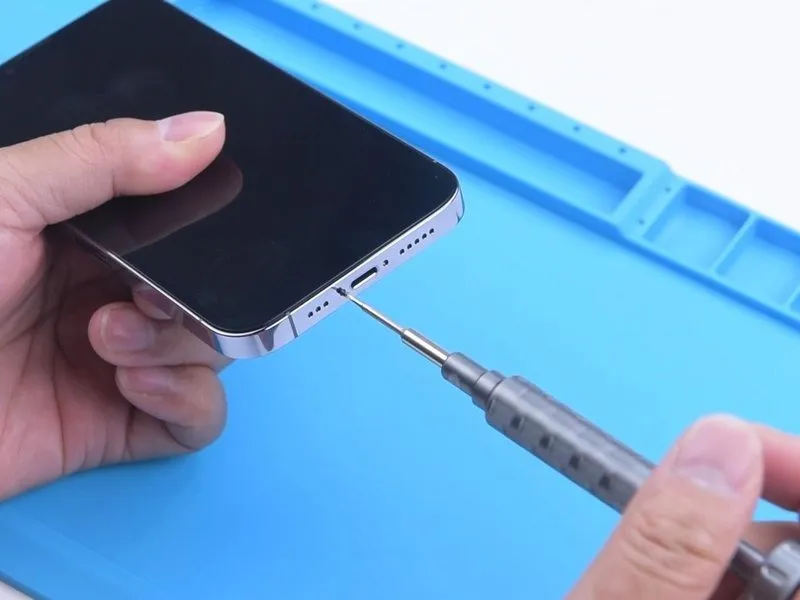
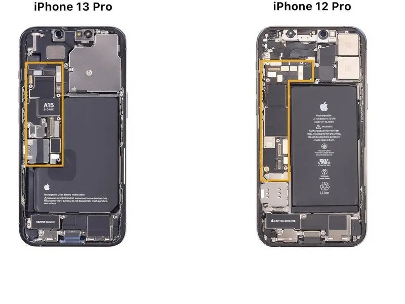
- Disassembly of the iPhone 13 Pro's mainboard is necessary to examine its internal components and diagnose the source of the overheating issue.This guide will detail the procedures for detaching and reattaching the mainboard.The iPhone 13 Pro's mainboard incorporates a smaller form factor, prioritizing increased battery capacity.
- A departure from previous designs, the mainboard now utilizes a non-L-shaped layout.Careful inspection of the internal architecture will be performed during the separation process.
Step 3
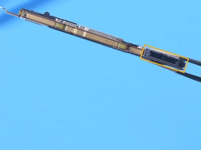
- Detach the motherboard assembly, noting that its construction incorporates a double-layered layout.
- The subsequent steps involve addressing a specific component.The SIM card reader, a crucial element for cellular connectivity, is integrated directly onto the motherboard via a soldered connection.This integrated design means the SIM card reader cannot be separated from the motherboard without causing damage.
Step 4
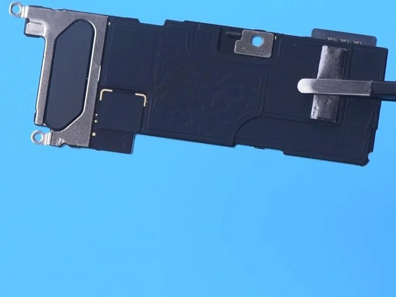
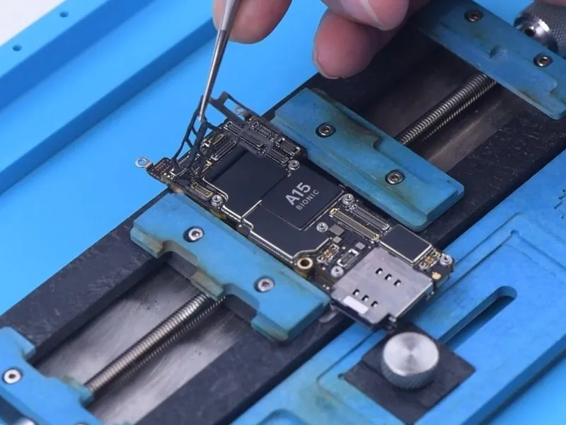
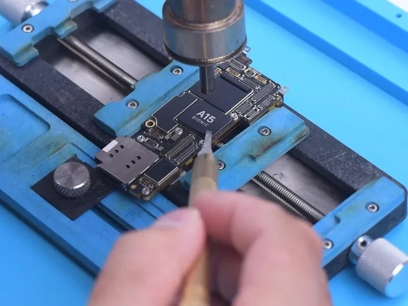
- To enhance thermal management, substantial heat dissipation tape is applied across the entirety of the motherboard's surfaces.
- Carefully detach the foam securing the motherboard's components.Utilize a Hot Air Gun, set to a temperature of 100 degrees Celsius, to carefully remove the adhesive tape.The NAND memory chips are located beneath the A15 tape layer.Application of heat facilitates the removal of the adhesive tape without damaging the underlying components.The heat dissipation tape's thickness contributes to improved thermal performance of the motherboard.
Step 5
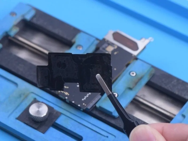
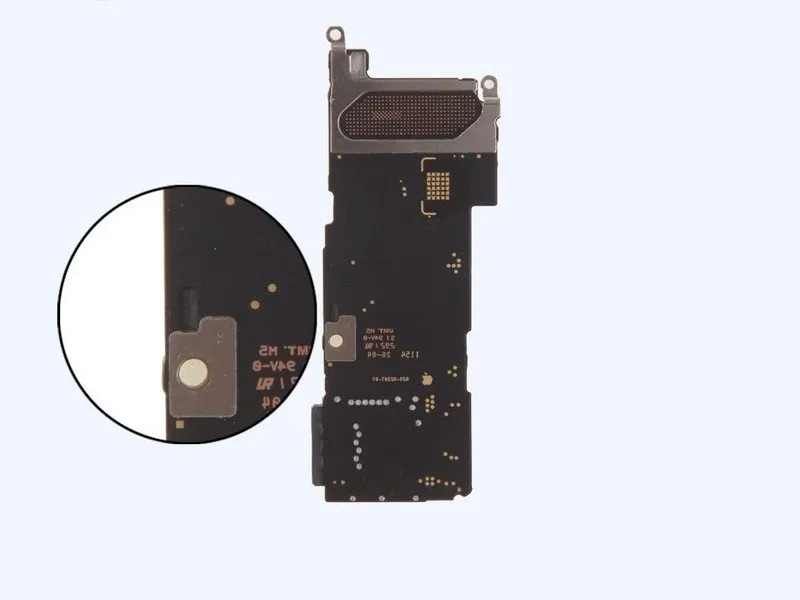
- Proceed with the removal of the adhesive strips located on the rear surface of the motherboard.The thermal insulation tapes affixed to the motherboard can be utilized again.Exercise caution during the repair process to prevent damage to these tapes, as doing so may compromise the motherboard's heat dissipation capabilities once reassembled.
- Note that the signal board of the iPhone 13 Pro has attached components on its backside; therefore, avoid any damage to these components during separation.
Step 6
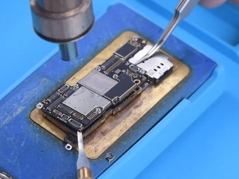
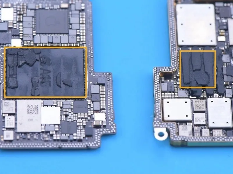
- Due to the unavailability of a dedicated heating platform specifically designed for the iPhone 13 Pro, a universal platform is employed for separation, operating at a temperature of 170 degrees Celsius.The iPhone 13 series motherboards retain a mid-temperature solder paste for their internal connections, necessitating careful thermal management.Apply heat to the motherboard vicinity using a hot air gun, setting it to 330 degrees Celsius, while the heating platform maintains a temperature of 150 degrees Celsius.
- As the motherboard loosens from its adhesive, carefully extract it using tweezers.Exercise caution to prevent damage to nearby components during the removal process.The central processing unit is integrated with the baseband chip, which hinders effective heat dissipation from the motherboard.The combined presence of the CPU and baseband creates a thermal bottleneck, complicating heat management.Maintaining a controlled temperature is crucial to avoid damaging sensitive components during the separation procedure.
- The universal heating platform serves as a temporary solution until a model tailored for the iPhone 13 Pro becomes available.
- Precise temperature regulation, at 170 degrees Celsius for platform separation and 330 degrees Celsius for hot air application, is essential for successful repair.
Step 7

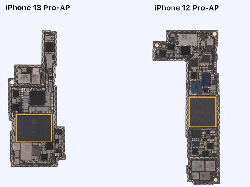
- To proceed with the repair, the existing thermal interface material must be carefully removed from the processor chips.
- The dimensions of the A15 chip have expanded significantly.Specifically, the A15 chip's size has grown considerably.This substantial increase in size complicates the process of desoldering the central processing unit.
Step 8
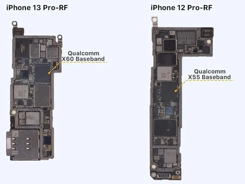
- The iPhone 13 Pro incorporates an updated Qualcomm X60 baseband processor, which is anticipated to enhance signal stability compared to earlier iterations.
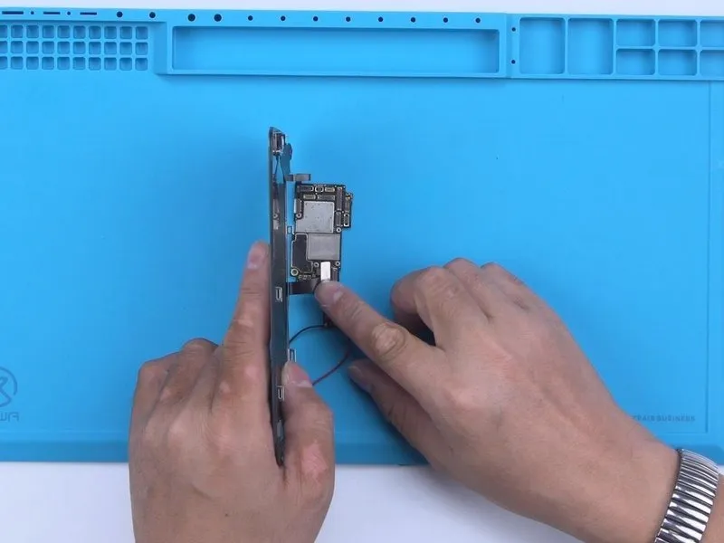
- To assess the viability of an iPhone 13 Pro logic board, apply a Direct Current Supply to initiate the boot sequence.
- Attach the display assembly and utilize tweezers to stimulate the boot-up process.
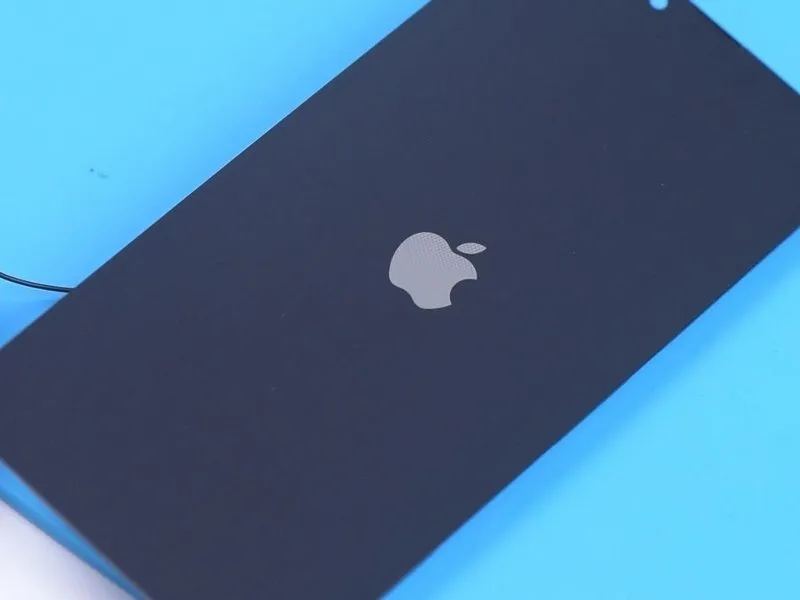
- The iPhone 13 Pro exhibits a prolonged boot-up duration, requiring approximately 8 to 10 seconds for the Apple logo to become visible, potentially attributable to alterations within the system architecture.
Step 9
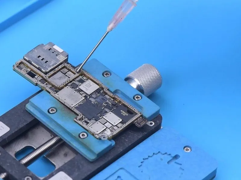
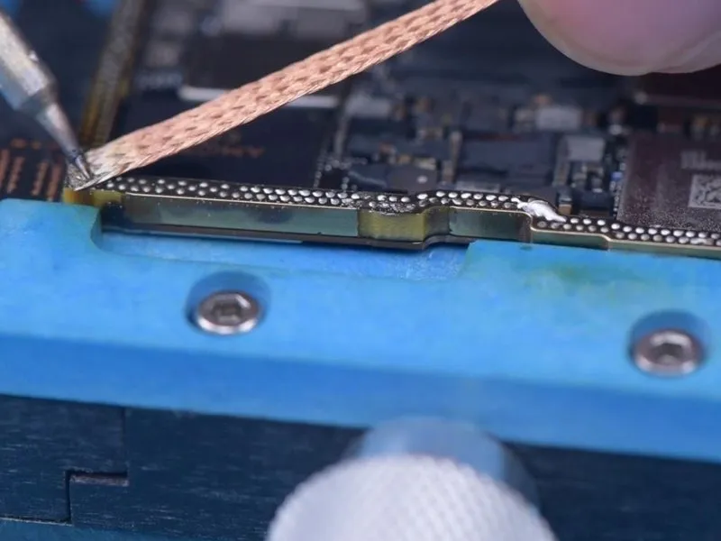
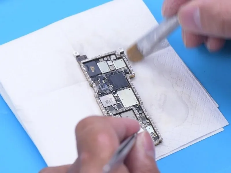
- Reattach the signal board to the logic board, ensuring proper alignment.
- For easier removal of excess solder later, a thin layer of low-temperature Solder Paste should be applied to the signal board's bonding pads.
- Employ a Soldering Iron, set to 380 °C, along with solder wick to effectively remove residue from the bonding pads.Apply a small amount of solder paste to the bonding pads located on the logic board, exercising caution to avoid contact with nearby components.During the process of removing excess solder with a Soldering Iron, it is crucial to prevent damage to adjacent components.The same care to avoid component damage must be observed when using the Soldering Iron to remove tin.Following soldering, use PCB Cleaner to ensure the bonding pads are free of contaminants.
- A thin layer of Paste Flux should be applied to the bonding pads of the signal board prior to reassembly.
Step 10
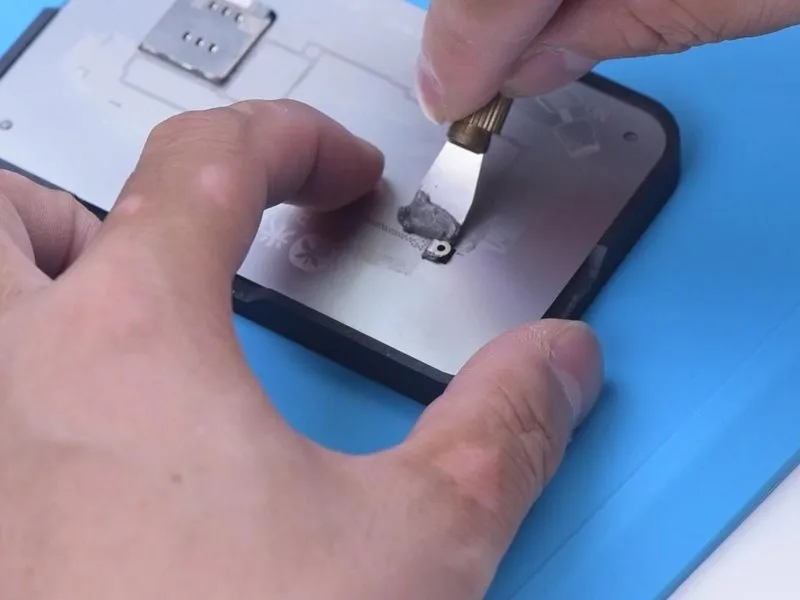
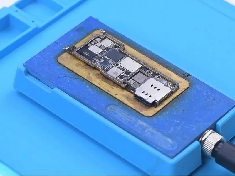
- The signal board undergoes reballing procedures; secure it to the Reballing Platform for proper alignment.
- Distribute middle-temperature solder paste uniformly across the designated areas.
- Following paste application, lift the reballing stencil and transfer the signal board to the Heating Platform to facilitate solder ball formation, subsequently allowing it to cool.
Step 11
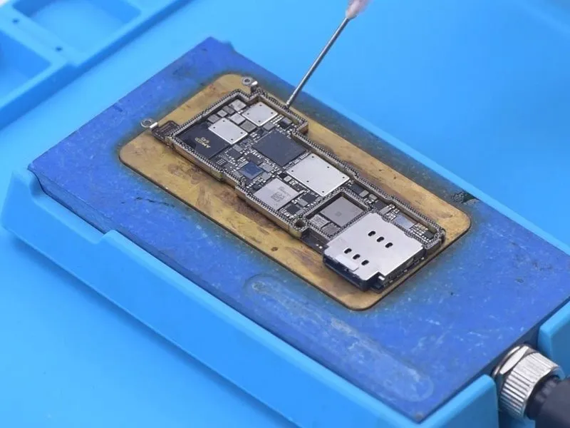
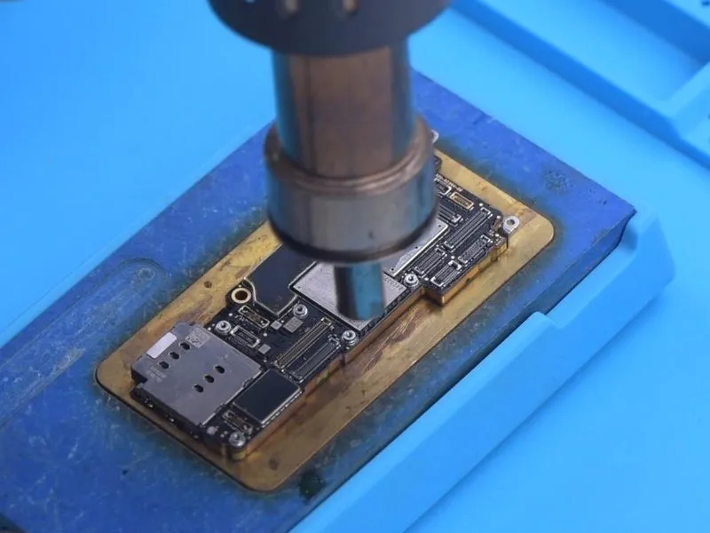
- To facilitate solder adhesion, dispense Paste Flux onto the designated bonding areas.
- Carefully position the logic board in relation to the signal board, ensuring precise alignment.
- Maintain the elevated temperature using the Heating Platform, sustaining a value of 170 degrees Celsius.The temperature should remain at 170 °C during this process.Utilize the Hot Air Gun to apply localized heat around the motherboard, setting the temperature to 330 degrees Celsius.
- Ensure the Hot Air Gun delivers heat at a temperature of 330 °C.Proper alignment and temperature control are crucial for successful bonding.These steps are necessary to ensure a secure and reliable connection between the boards.
Step 12
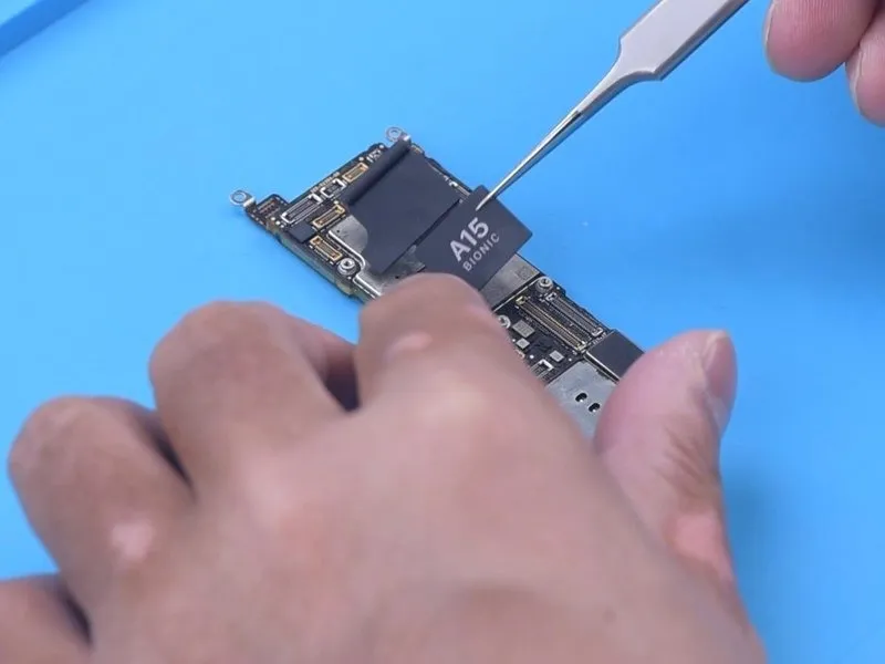
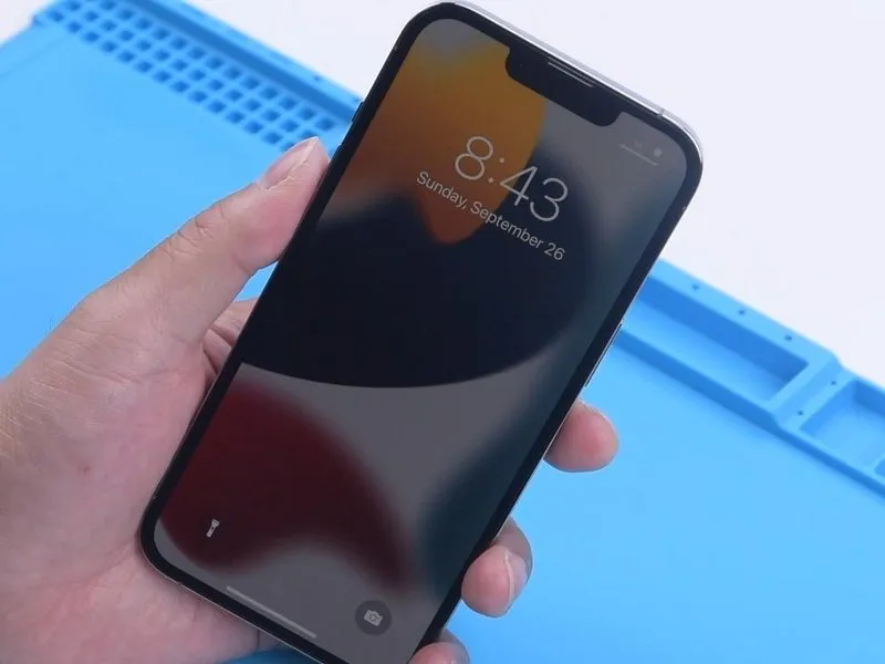
- Once the motherboard's temperature has decreased to a safe level, disconnect it from the device.
- Apply fresh foam and heat dissipation adhesive strips to the motherboard's surface.
- Reintegrate the motherboard into the device and perform a functional test, verifying normal power-on behavior.
- This disassembly process confirms the iPhone 13 Pro retains a dual-layer motherboard design, exhibiting minor cosmetic alterations while maintaining a consistent primary chip layout.