iPhone 13 Pro Max Screen Replacement
A damaged iPhone 13 Pro Max display, exhibiting cracks, unresponsive touch input, or a blank image upon power-on, can be repaired following the instructions in this guide, replacing the display assembly.Please be aware that functionality for True Tone and automatic brightness adjustment will be lost after screen replacement on iOS versions prior to 17.6, even when utilizing a genuine Apple display.The Face ID security feature will also become inactive unless the device is operating with iOS 15.2 or a later version.
- Conversely, iOS 18 and subsequent versions allow for screen calibration via Apple's Repair Assistant, potentially restoring True Tone capabilities when using authentic Apple replacement screens.This procedure involves the complete replacement of the display assembly, which incorporates the screen itself.The guide is designed to return the iPhone 13 Pro Max to a fully operational state.Genuine Apple replacement screens are required to benefit from the calibration functionality introduced in iOS 18 and beyond.
- Prior to commencing the repair, understand that certain features are impacted by iOS version limitations.The described repair process focuses on restoring visual output and touch responsiveness through display assembly substitution.
Step 1 | Remove the pentalobe screws

- Using appropriate tools, unscrew and remove the pair of pentalobe screws, each measuring 6.8 mm in length, located on the iPhone's lower edge.
- Separating the display assembly from the iPhone body will irreversibly damage the device's water resistance capabilities.
Step 2 | Mark your opening picks


- To ensure proper depth, utilize a permanent marker to indicate a point 3 millimeters from the pick's distal end.
- For enhanced precision, consider marking the pick's other corners with varying measurements to accommodate different scenarios.
- As an alternative method for depth control, affix a coin to the opening pick, positioning it precisely 3 millimeters from the tip.
Step 3 | Tape over any cracks


- Apply multiple layers of transparent packing tape across the entire display surface, ensuring they overlap.
- This containment method will hold glass fragments in place and maintain the screen's stability during separation.
- Always utilize eye protection to guard against dislodged glass fragments throughout the repair process.
- Should the suction cup fail to adhere properly, create a handle with a durable tape, like duct tape, to facilitate screen lifting.
- As a last resort, a small amount of superglue can be used to temporarily secure the suction cup to the display.
Step 4 | Anti-Clamp instructions


- Detailed operational guidance for the Anti-Clamp is accessible through a separate, dedicated instructional document.
- To release the locking mechanism, retract the blue handle, which will disengage the Anti-Clamp's gripping arms.
- Carefully position the arms across the left side of the iPhone's casing.
- Place the suction cups in close proximity to the lower edge of the iPhone, ensuring one cup is situated on the front surface and the other on the rear.
- Apply pressure by compressing the cups together, establishing a secure vacuum seal on the intended surface area.
- Should the iPhone's exterior prove excessively smooth, preventing adequate adhesion by the Anti-Clamp, utilize the provided adhesive pad to enhance surface friction.
Step 5


- Rotate the handle in a clockwise direction until visual confirmation of the cups undergoing deformation is observed.
- Maintain the positional integrity of the suction cups relative to one another; should misalignment occur, slightly reduce the suction force and readjust the arm positions.
Step 6


- Ensure the iPhone rests securely on a stable surface throughout the repair process.
- Apply warmth to the iPhone's lower edge utilizing a hair dryer; the display surface should reach a temperature just beyond comfortable touch.
- Refer to a dedicated instructional resource for detailed guidance on the proper operation of a hair dryer.
- Allow a sixty-second period to elapse, enabling the adhesive to soften and create a discernible separation.
- Introduce an opening tool beneath the display assembly once the Anti-Clamp device establishes a noticeable space.
- Should the Anti-Clamp fail to generate an adequate separation, increase the heat applied to the area and rotate the handle by ninety degrees.
- Avoid rotating the handle beyond a ninety-degree increment at any point, and incorporate a sixty-second pause between each rotation to allow the device and time to facilitate the separation.
- Proceed past the subsequent three procedural stages.
Step 7 | Heat the bottom edge

- Apply warmth to the iPhone's lower border using a hair dryer or heat gun, ensuring the screen's temperature reaches a point just beyond comfortable touch.
- Avoid prolonged, concentrated heat application from the hair dryer to prevent localized overheating.
Step 8 | Insert an opening pick
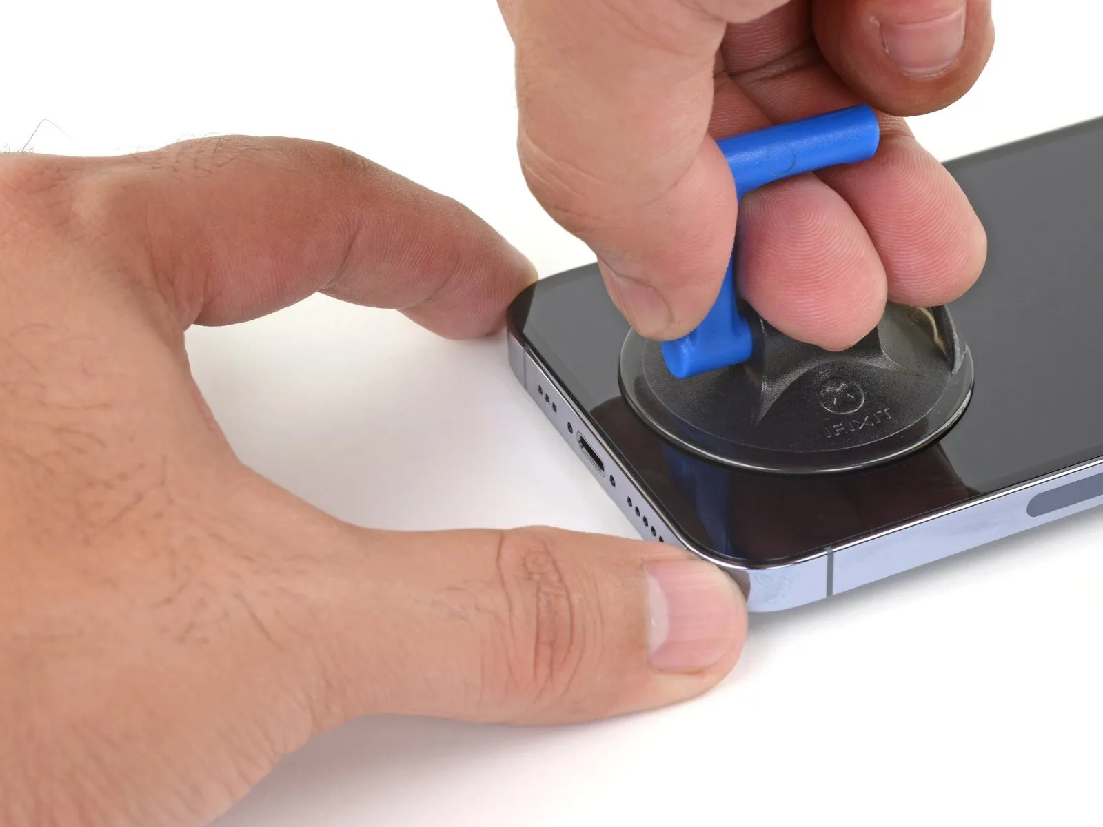
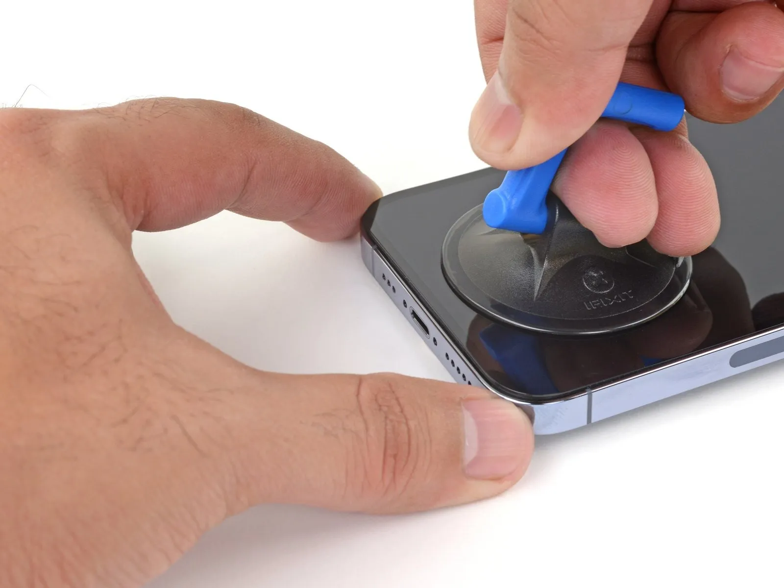
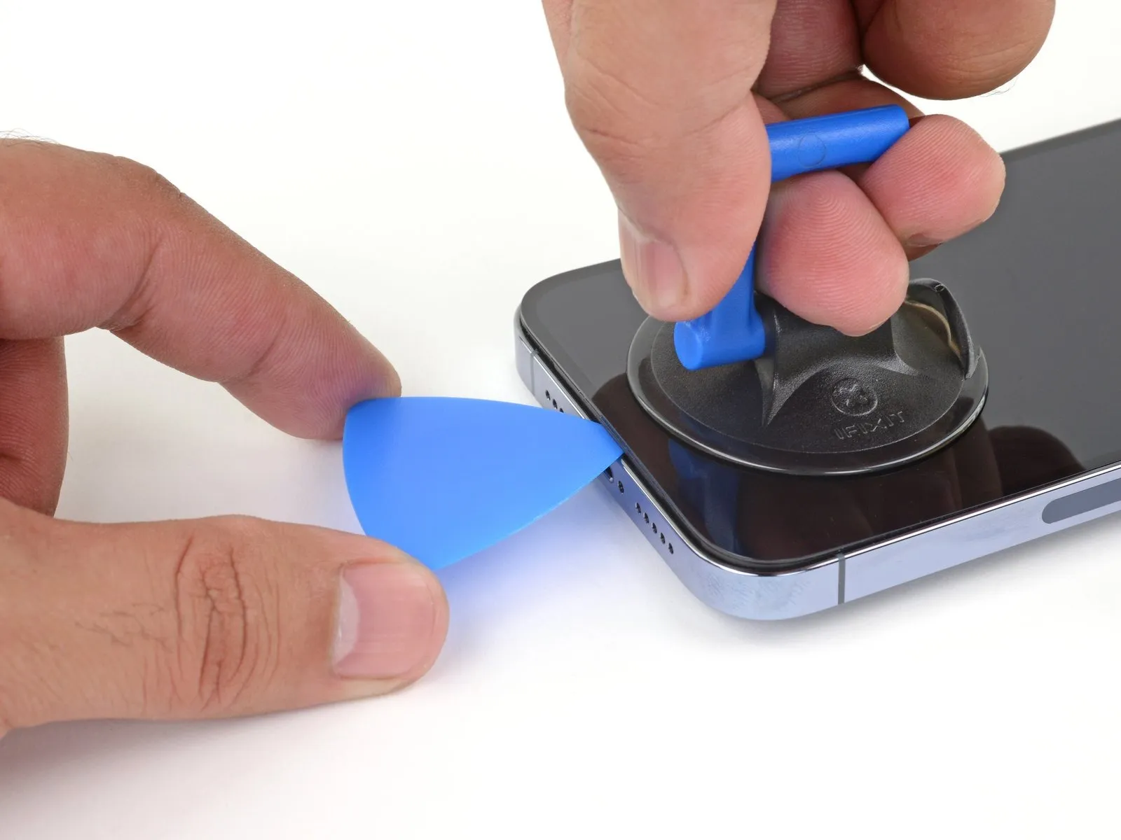
- Secure a suction handle to the lower perimeter of the device, ensuring it's positioned away from the screen's outermost boundary.
- Maintain consistent, substantial upward force on the suction cup to generate a small separation between the front display assembly and the device's back enclosure.
- Introduce an opening tool into the newly formed separation.
- Due to the robust nature of the waterproof sealant securing the display, considerable force is required for initial separation; if encountering difficulty, apply additional heat and gently oscillate the screen to reduce adhesive strength until a sufficient gap is achieved for tool insertion.
Step 9 | Separate the bottom edge adhesive


- Ensure the initial insertion of your opening tool does not exceed a depth of 3 millimeters from the lower border.Employ a reciprocating motion with your tool across the lower edge to sever the adhesive bond.The adhesive layer's integrity can be maintained by keeping the tool positioned within the lower-rightmost section.
- Maintaining the tool's position prevents the adhesive from reforming a seal.
- A maximum insertion depth of 3 mm is critical when working along the lower edge.
Step 10 | Heat the right edge


Apply warmth to the right-hand perimeter of the iPhone using a hair dryer, focusing on the area containing the power button, until the surface temperature reaches a point where it is noticeably warm but still tolerable to the touch.The purpose of this heating process is to soften the adhesive securing the display assembly, facilitating its separation from the device's frame.Exercise caution to prevent overheating, as excessive heat can potentially damage internal components; maintain a comfortable, slightly warm temperature on the screen's edge.
Step 11 | Separate the right adhesive
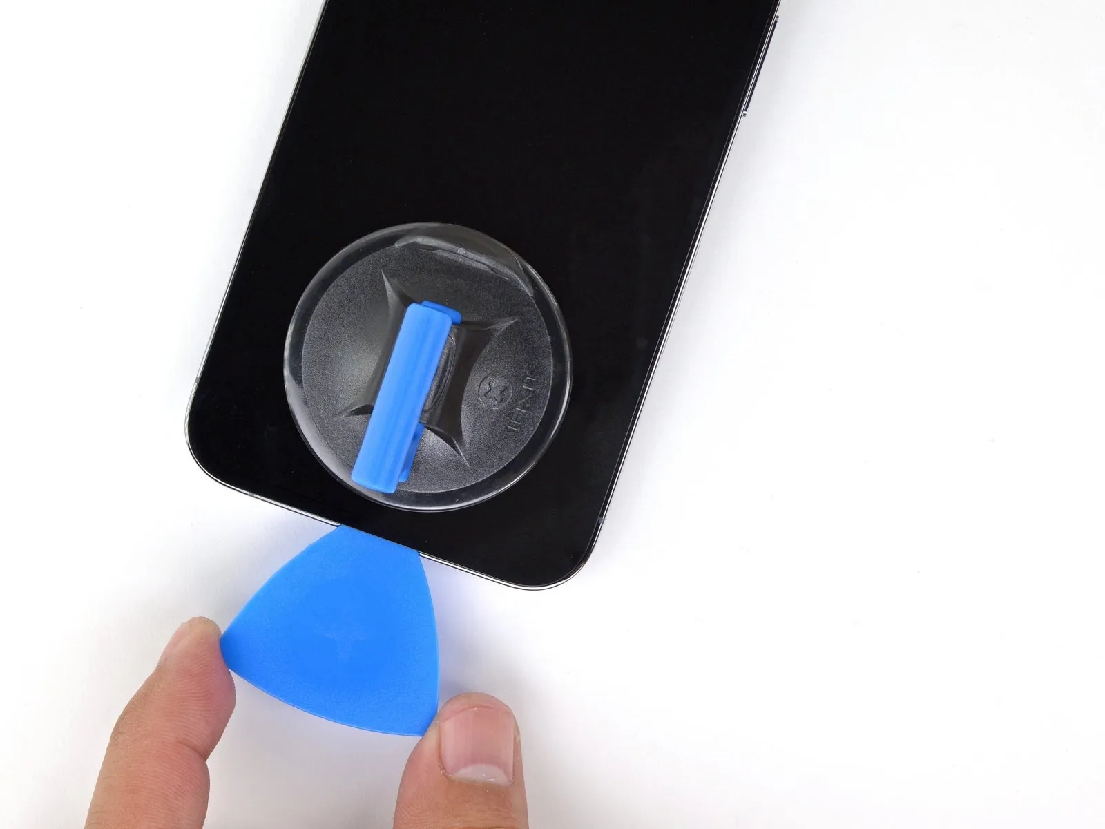
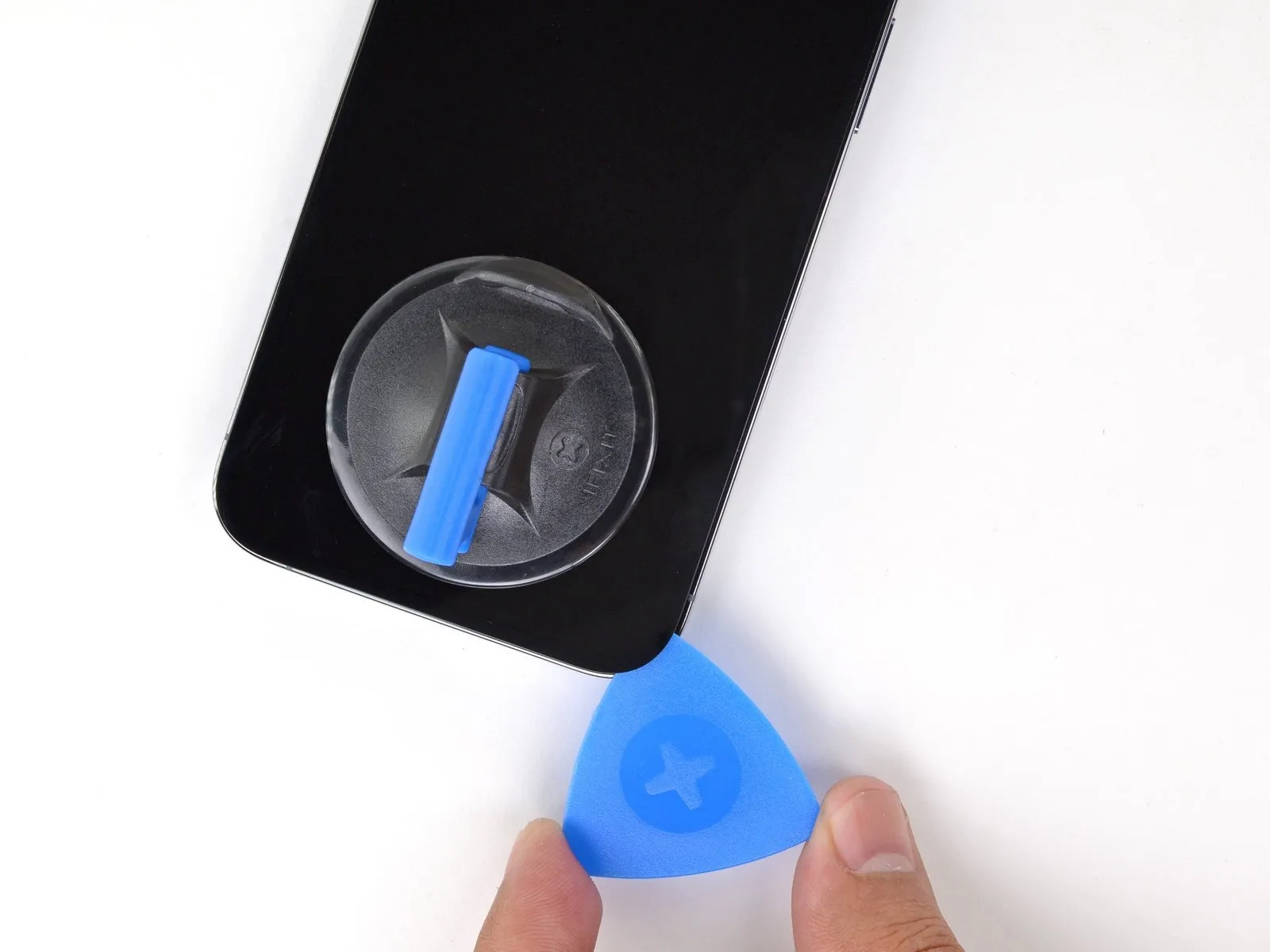
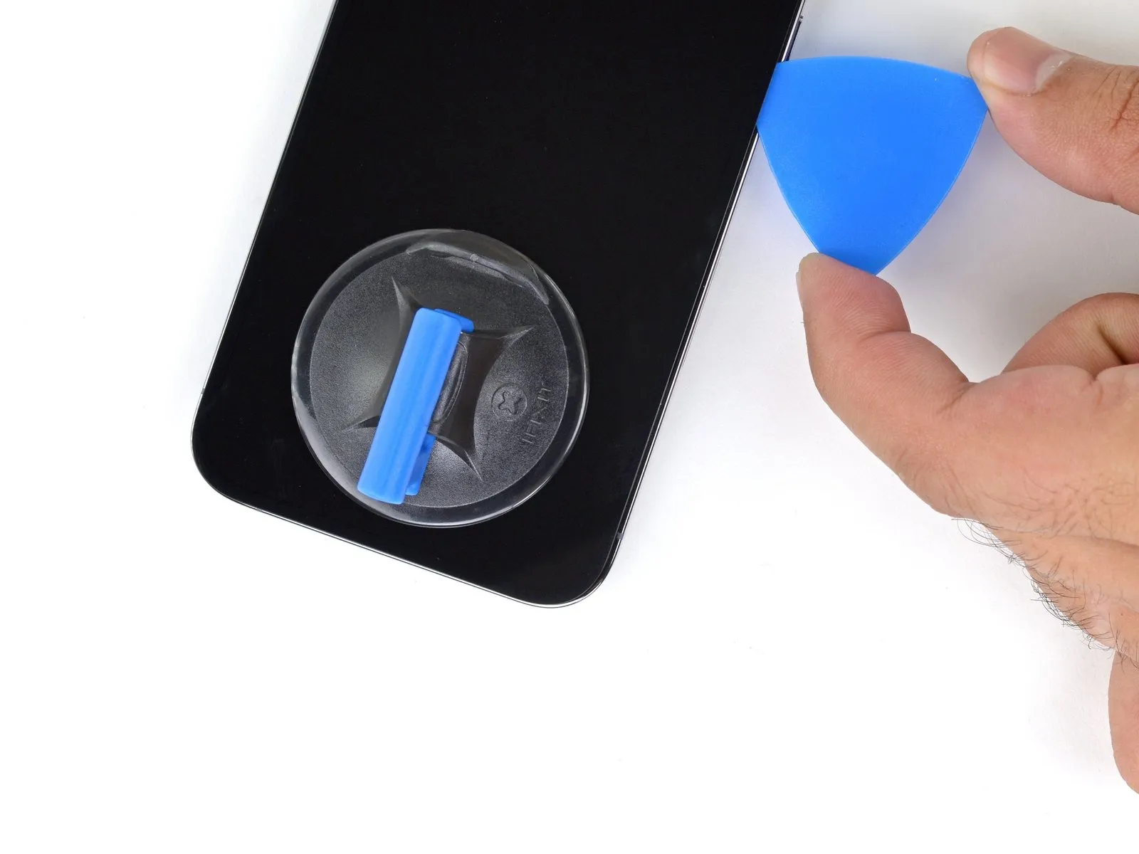
- Utilize a specialized opening pick, carefully maneuvering it along the lower-right perimeter of the iPhone to release the securing adhesive.
Progressively slide the pick upwards along the right side of the iPhone's casing, advancing until the top-right corner is reached.
A critical precaution: restrict the pick's insertion depth to a maximum of 3 millimeters to prevent potential harm to delicate internal parts.Maintaining the pick's position within the top-right corner is essential before proceeding with subsequent steps.The adhesive bond is released by sliding the opening pick around the lower-right edge of the iPhone's enclosure.
To avoid internal component damage, ensure the pick does not penetrate beyond a depth of 3 millimeters.
Step 12 | Heat the top edge

Apply warmth to the iPhone's upper border utilizing a hair dryer, ensuring the surface temperature reaches a point just beyond comfortable touch.
Step 13 | Separate the top adhesive


- Utilize a specialized opening tool to carefully release the adhesive securing the iPhone's top right edge.
Exercise caution to prevent damage to the delicate upper sensors; insertion depth should not exceed 3 millimeters.Maintaining the pick's position in the upper left corner is necessary for subsequent steps.The adhesive bond between the device and its enclosure requires separation using a thin, flexible tool.
To avoid potential harm to the proximity and ambient light sensors, limit the pick's penetration to a maximum of 3 mm.
Step 14 | Screen information

Fragile wiring is situated along the iPhone's left side; avoid inserting any tools in this area to prevent cable damage.
Step 15 | Heat the left edge


Apply warmth to the iPhone’s left lateral border utilizing a hair dryer, continuing until the screen surface reaches a temperature just beyond comfortable touch.
Step 16 | Separate the left adhesive


- Fragile wiring is situated along the iPhone's left side.Insertion of the opening tool should not exceed a depth of 2 millimeters to prevent cable damage.Perform a rotational movement of the tool around the screen's upper-left quadrant.
- Advance the tool along the left edge to release the adhesive bond.
- Should adhesive separation prove difficult, applying heat to the left edge may be necessary.
- Reheating the left edge can facilitate adhesive release if separation is problematic.
Step 17 | Open the iPhone

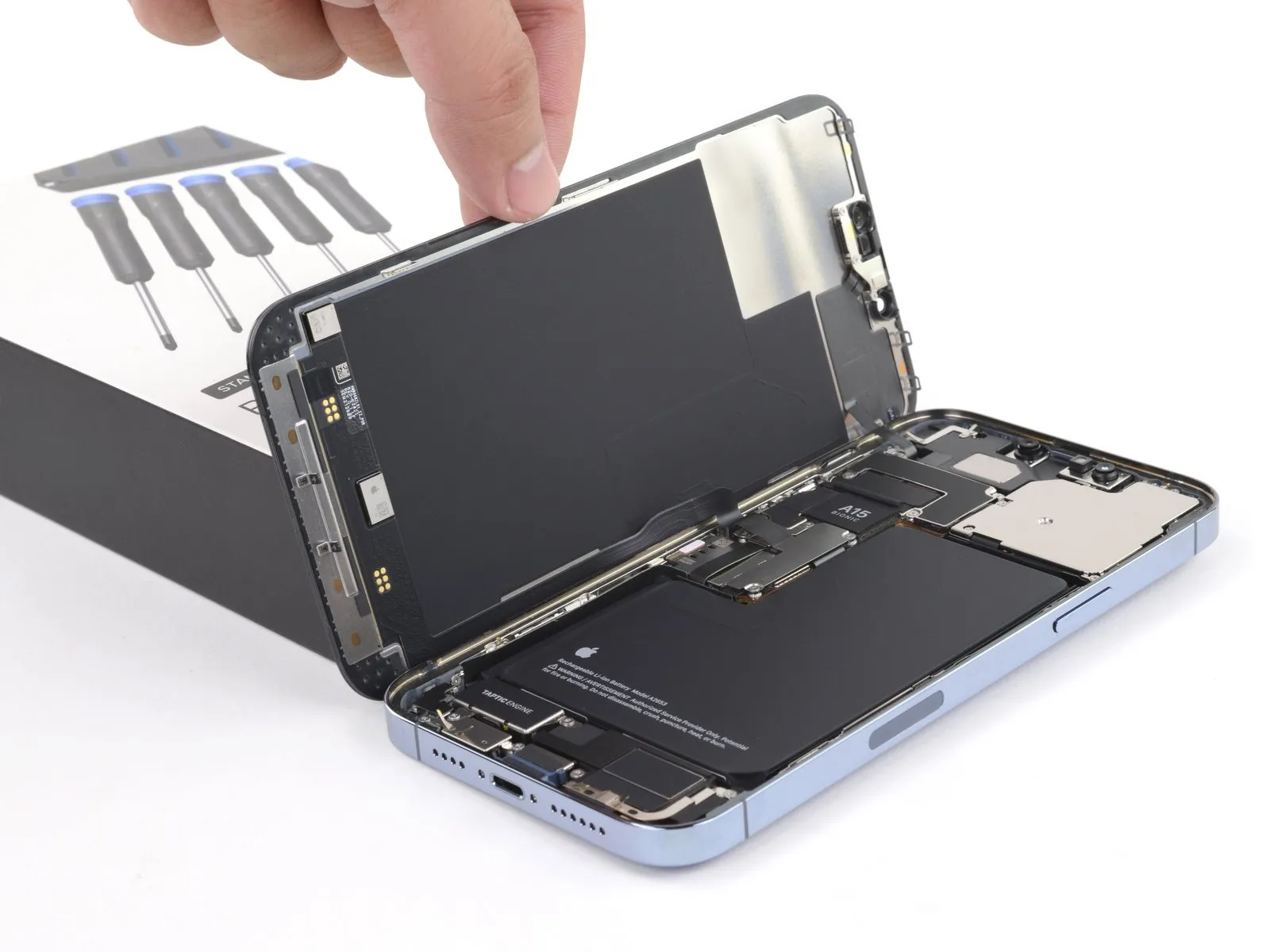
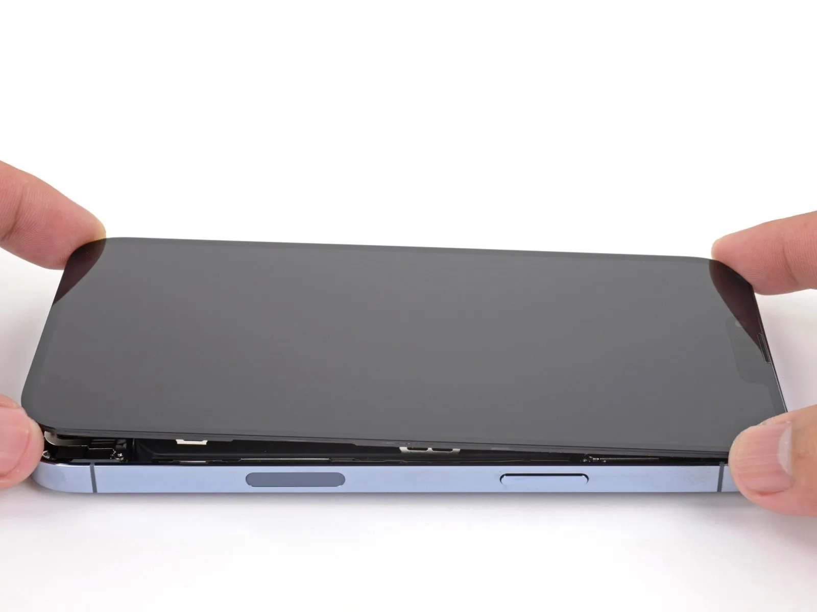
- Detach the suction handle from the display surface.
- Initiate the iPhone's opening procedure by pivoting the display upwards from the right side, mimicking the action of opening a book's cover.
- Refrain from completely disconnecting the display at this stage, because multiple delicate ribbon cables remain attached to the iPhone's logic board.
- Secure the display in an upright position using a support to maintain access to the internal components.
- When reassembling, position the display, ensuring the top edge clips are properly aligned, and then apply gentle pressure to the top edge before securing the remainder of the display; if resistance is encountered, inspect the display's perimeter clips for any deformation.
Step 18 | Remove the battery connector cover

- Employ a Y000 screwdriver for the removal of the three 1.3 mm screws that fasten the battery connector cover.Carefully monitor the location of each screw during disassembly, ensuring correct placement during reassembly to prevent potential damage to the iPhone.A functional test of all iPhone features is recommended at this stage, prior to final display reattachment, by briefly powering on the device.Ensure complete power-off of the iPhone before proceeding with subsequent repair steps.The three 1.3 mm screws hold the battery connector cover in place, necessitating their removal with a Y000 screwdriver.
- Maintaining accurate screw placement is crucial to avoid inflicting harm to the iPhone's internal components during the repair process.
- Before securing the display, a brief power-on and comprehensive functional verification of the iPhone is advisable.
Step 19

Step 20 | Disconnect the battery

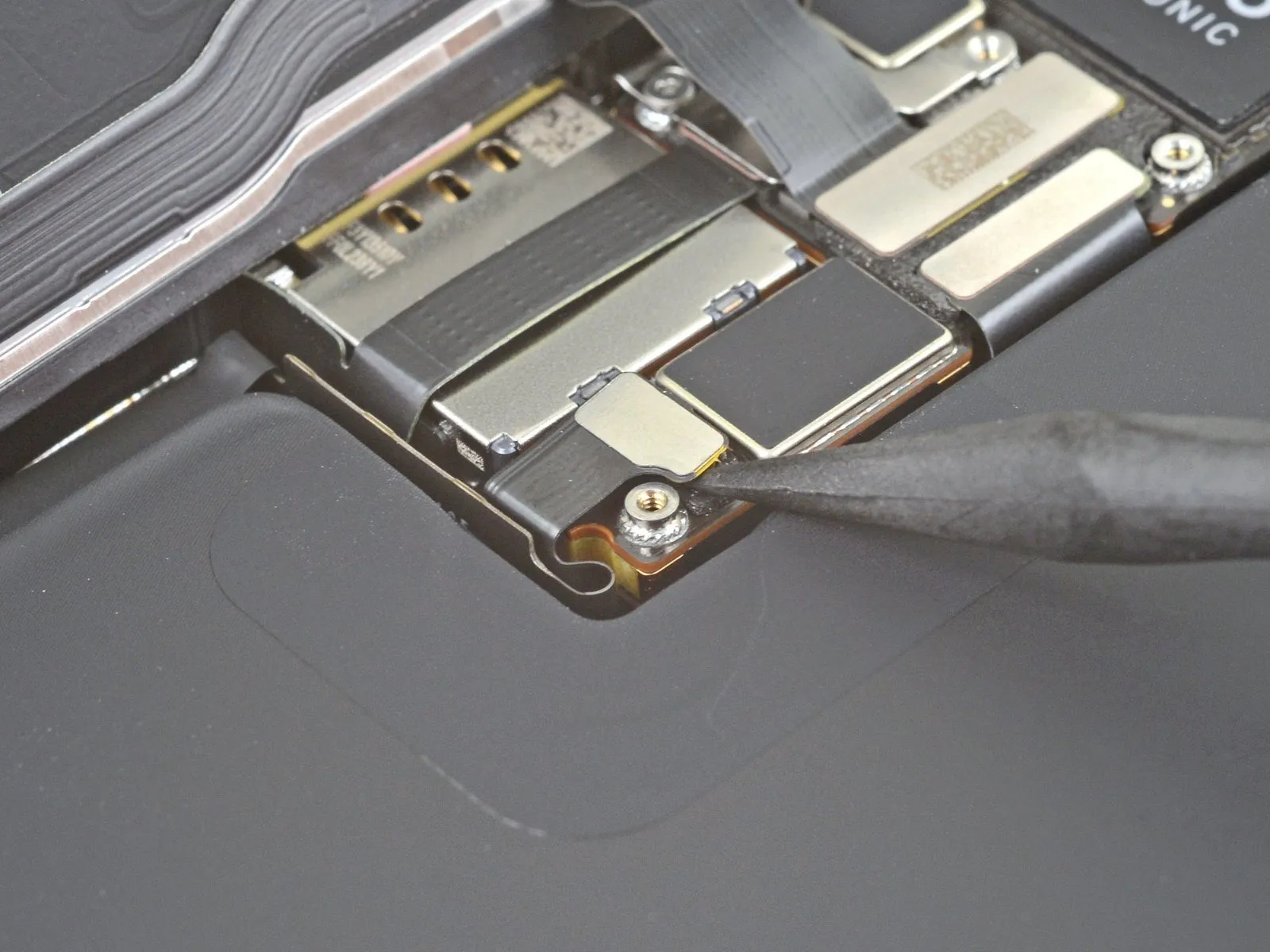
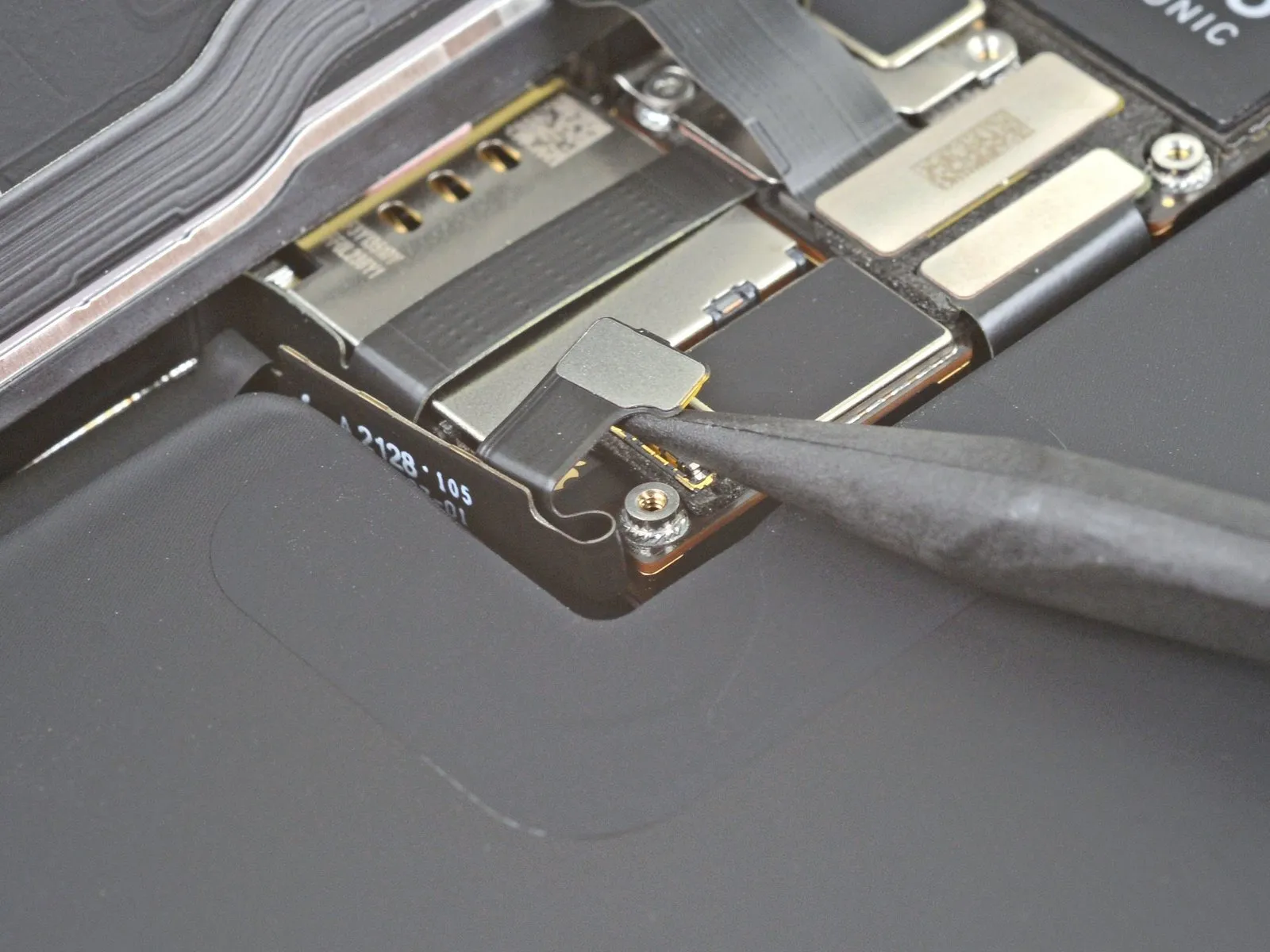
- Employ the tapered tip of a spudger, or a clean fingernail, to lift the battery connector's retaining clip from its corresponding receptacle on the logic board.Exercise caution to avoid harming the black silicone sealant that surrounds this connector and others on the board, as it offers supplemental protection against water and particulate contamination.Slightly deflect the connector away from the logic board's surface to ensure it remains disconnected and prevents unintended power delivery to the device during the repair process.
- The silicone seals are critical for maintaining the device's environmental resistance, so their integrity must be preserved.
- Careful manipulation of the battery connector is essential to prevent accidental re-engagement with the socket, which could energize the phone during the repair.
Step 21 | Disconnect the display cable

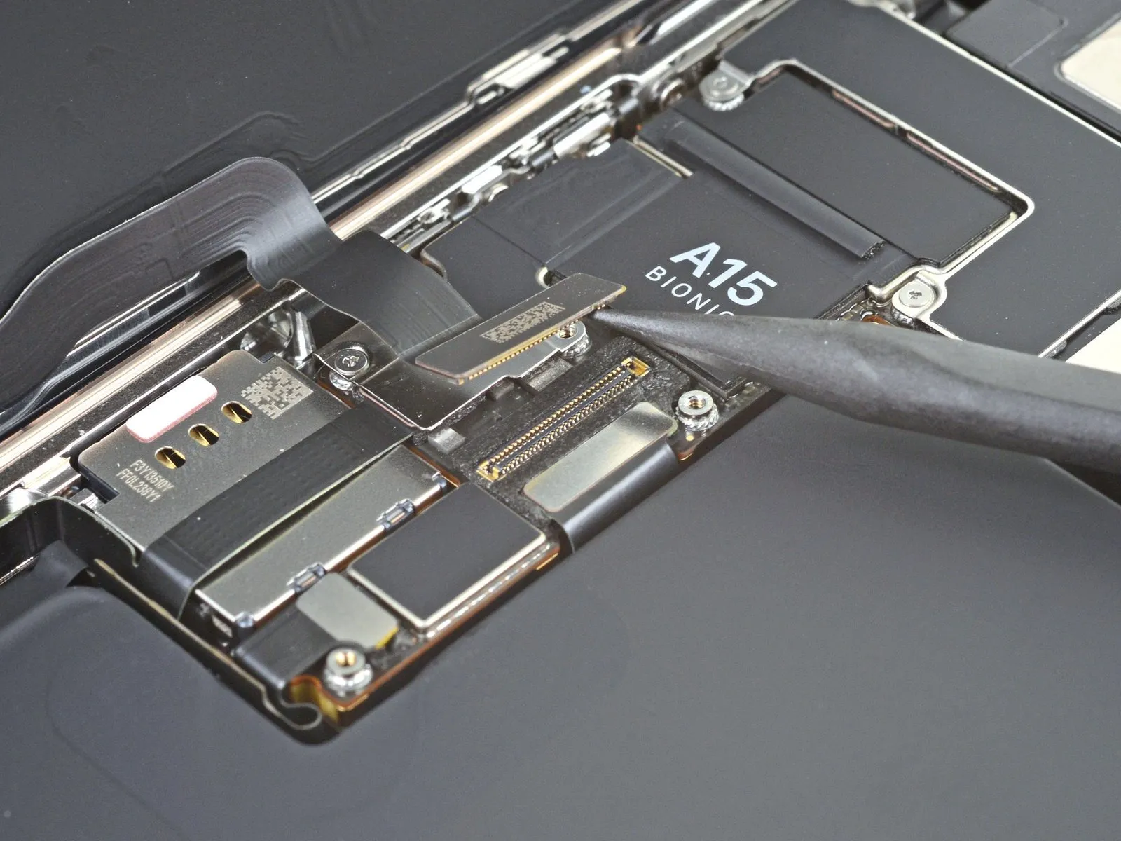
- Employ the tapered tip of a spudger, or a similarly shaped clean fingernail, to elevate the display connector away from its corresponding socket situated on the logic board.For reconnection, position the connectors identically to their original state, then apply downward pressure sequentially to each side until an audible click confirms secure engagement; avoid central pressure.Misalignment during reattachment carries the risk of pin deformation, which can result in irreversible component failure.
- Careful alignment and controlled pressure are essential during the reattachment process to prevent damage to the delicate connector pins.
Step 22 | Unscrew the front sensor connector cover

- Employ a Y000 screwdriver for the removal of the two 1.1 mm screws securing the front sensor connector cover.The front sensor connector cover is held in place by two screws that require a Y000 screwdriver for disassembly.To detach the front sensor connector cover, utilize a Phillips screwdriver.The remaining fasteners on the front sensor connector cover necessitate a Phillips screwdriver for their removal.A single 1.5 mm screw is also present.
- Additionally, a 1.8 mm screw is incorporated into the assembly.The front sensor connector cover's retention is achieved through a combination of screw sizes.Disassembly of the front sensor connector cover requires careful selection of appropriate screwdriver types.
- The 1.1 mm screws are accessible with a Y000 screwdriver.Phillips head screws are used in conjunction with the 1.1 mm screws to secure the cover.
- Ensure proper screwdriver engagement to prevent damage to the screw heads during removal.The screw sizes, 1.1 mm, 1.5 mm, and 1.8 mm, are critical for reassembly.
Step 23
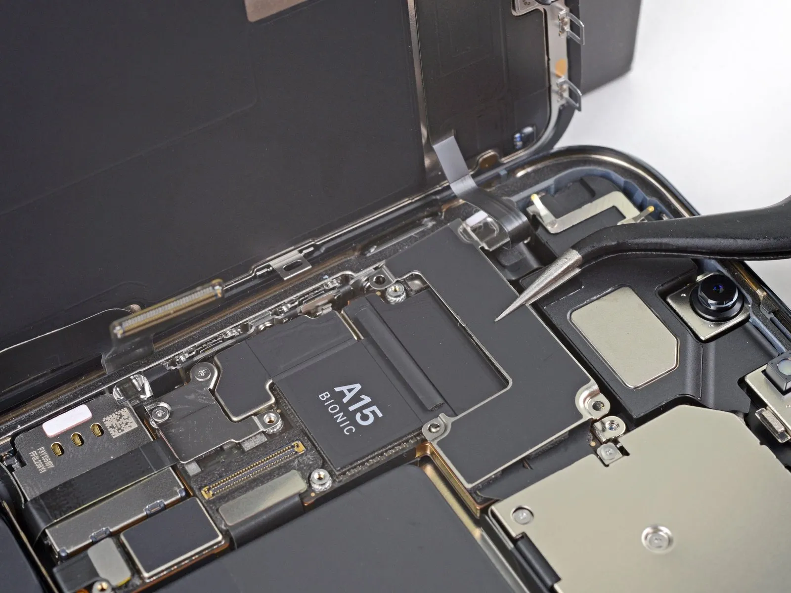
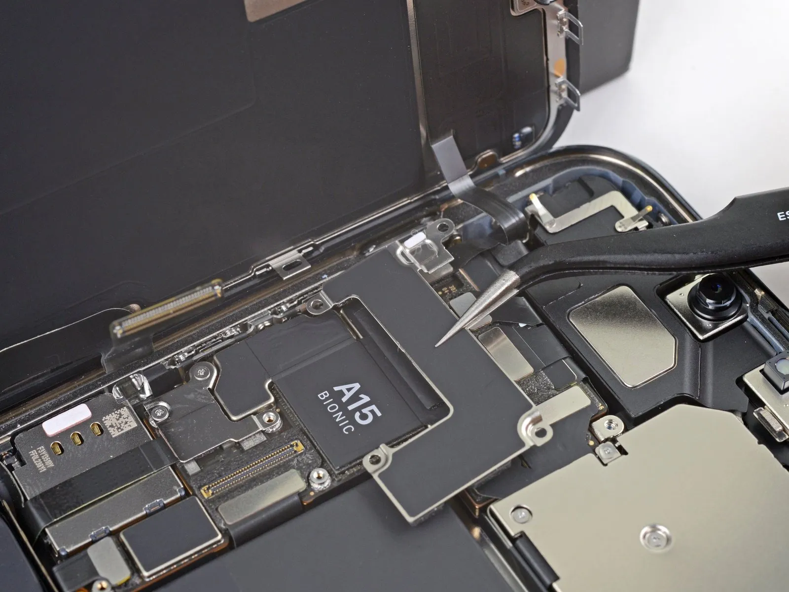
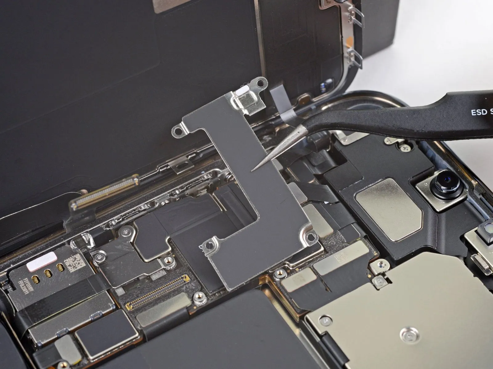
To access the front sensor connector, detach the protective cover.
Step 24
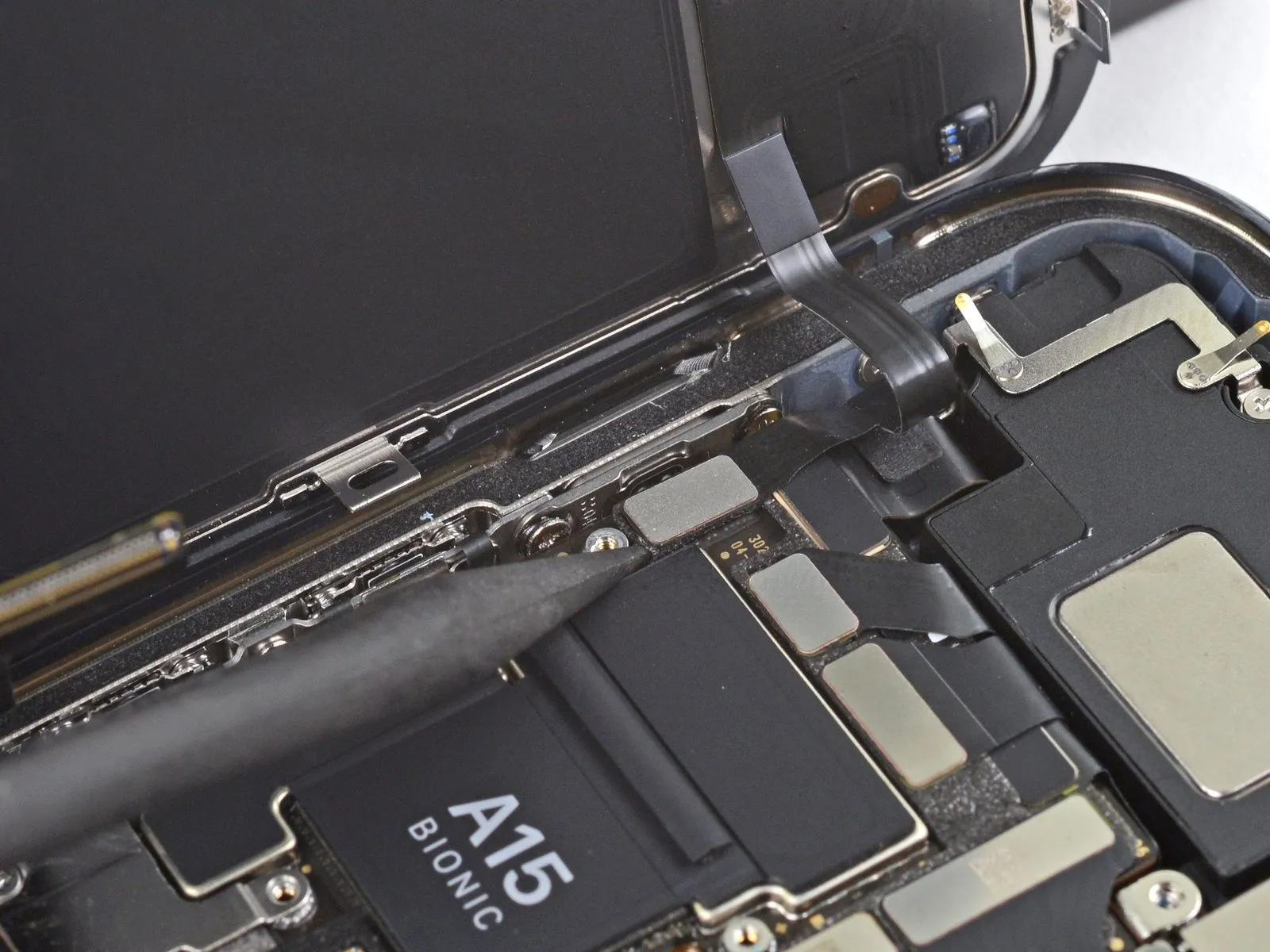
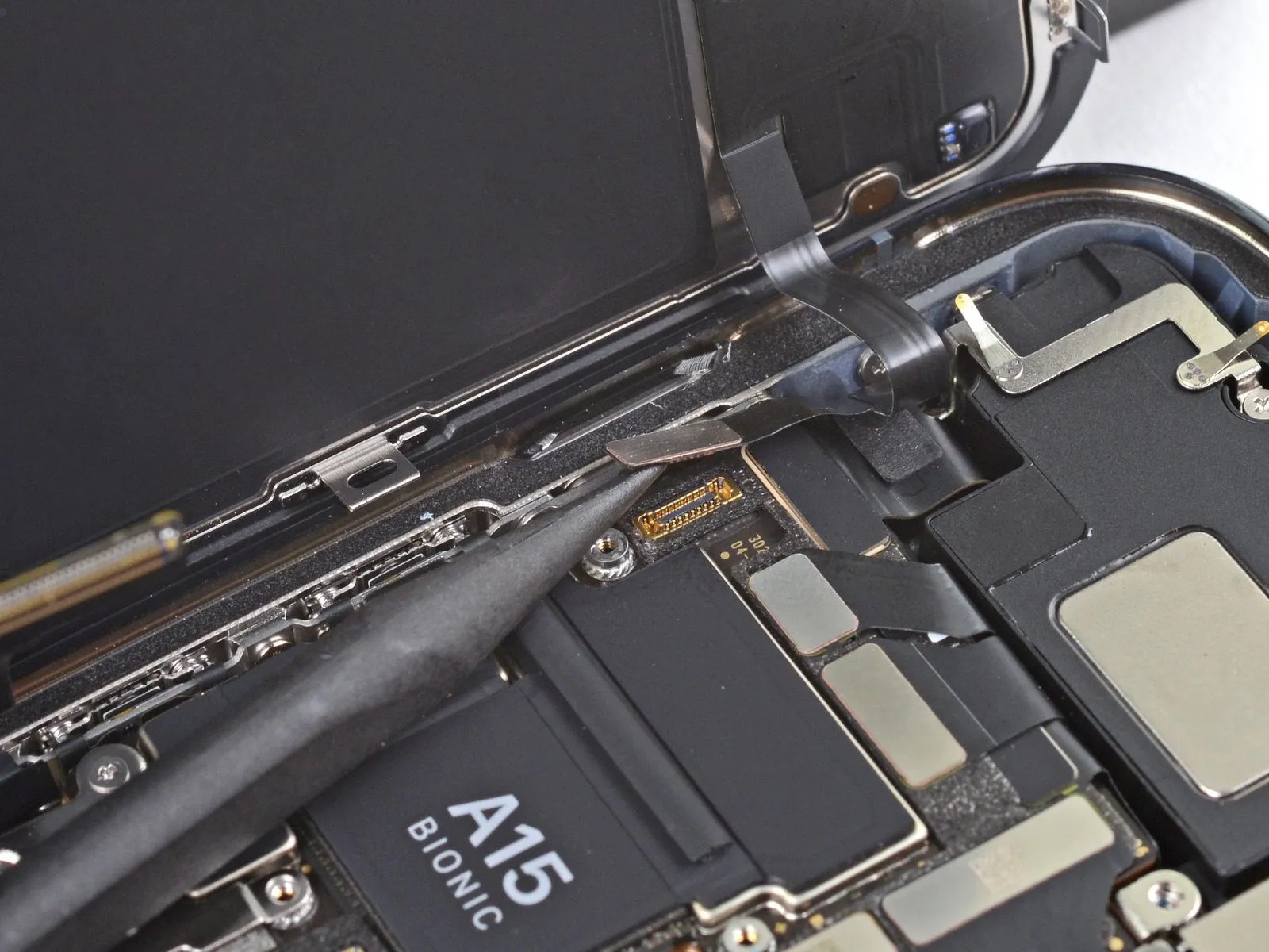
Employ the tapered tip of a spudger to release the front sensor assembly cable connector.The front sensor assembly cable connector must be detached utilizing a spudger's pointed end.A spudger, specifically its pointed end, is necessary for separating the front sensor assembly cable connector.
Step 25
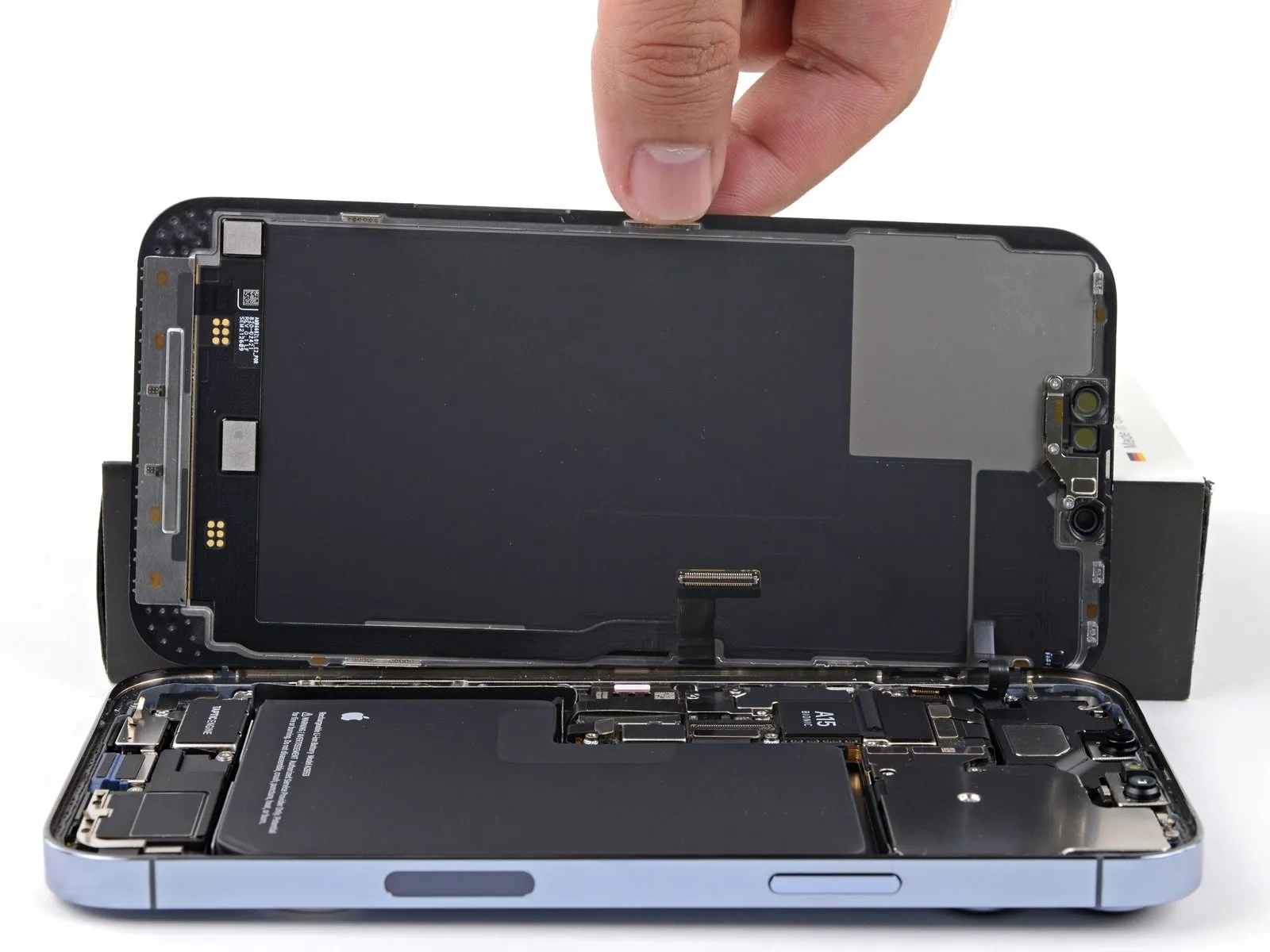
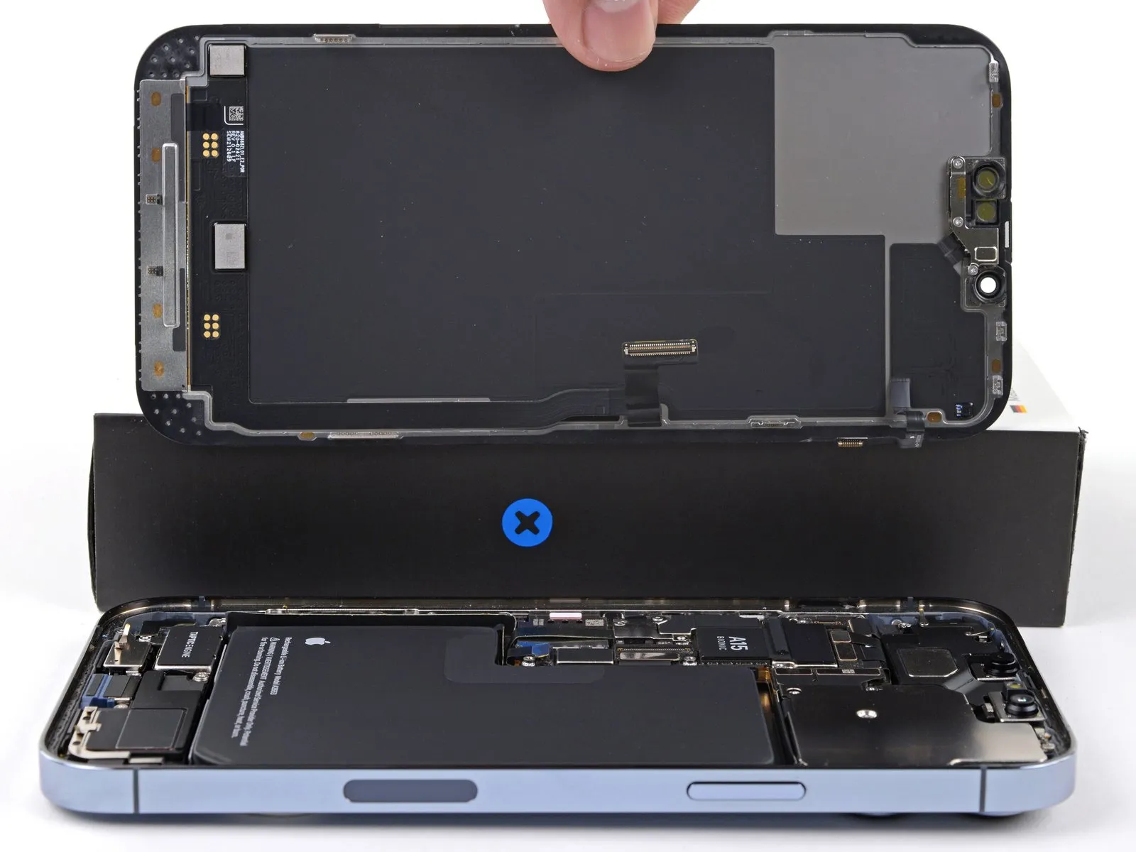
- Detach the display unit from the device.
- If substituting the waterproof adhesive sealant that borders the display during reinstallation, halt the process at this stage.
Step 26 | Unfasten the front sensor bracket

- The subsequent procedures illustrate the process of relocating the front sensor assembly onto a replacement display panel.
- Employ a Y000 screwdriverto detach the three screws, each measuring 1.4 millimeters in length, which fasten the front sensor assembly bracket.
Step 27 | Remove the front sensor bracket


- Employ tweezers or your fingertips to detach the front sensor assembly bracket.
Step 28 | Heat the front sensor assembly

- Employing a heated iOpener, apply it to the phone's upper screen border, maintaining contact for a duration of two minutes.
- Alternative heat sources, such as hair dryers, heat guns, or hot plates, can be utilized; however, exercise caution to prevent excessive temperatures, as the display panel is vulnerable to heat-related degradation.
Step 29 | Disconnect the ambient light sensor


- Position a specialized opening tool within the gap located between the ambient light sensor and the surrounding screen area.The tool should be carefully inserted to facilitate separation.Apply gentle upward pressure with the opening tool to disengage the ambient light sensor from the display panel.
- This action will create a space allowing for subsequent component removal.
Step 30 | Disconnect the proximity sensor


- Position a specialized opening tool within the gap located between the proximity sensor and the surrounding area of the display assembly.The tool should be carefully inserted to facilitate separation.Apply gentle upward force utilizing the opening tool to disengage the proximity sensor from the screen's surface.
- This action creates a space allowing for subsequent component removal, ensuring the sensor is detached without damage.
Step 31 | Reposition the proximity sensor


Employ tweezers or your fingertips to reposition the proximity sensor cable.The proximity sensor cable must be carefully displaced from the display assembly.Ensure the proximity sensor cable is moved clear of the screen's surface using a suitable tool or manual manipulation.
Step 32 | Disconnect the microphone


- Position a thin, flat tool, designated as an opening pick, beneath the microphone cable's entry point, situated near the microphone's metallic housing.Carefully maneuver the opening pick along the microphone's outer edges to detach the adhesive securing it.The microphone's enclosure is a rectangular metal component.
- By sliding the opening pick completely around the microphone's boundary, the adhesive bond will be released.
Step 33 | Remove the front sensor assembly


- The bonding agent might be solidified by this stage; if so, use a heated iOpener for a duration of sixty seconds prior to proceeding.Employ an opening pick to gain access beneath the left edge of the front sensor assembly.Advance the pick along the underside of the assembly to disengage it from the device's frame.
- A temperature of approximately 80°C (176°F) is recommended when utilizing the iOpener to soften the adhesive.
- Care must be taken to avoid damaging the front sensor assembly during separation from the frame.
Step 34


- Detach the front sensor assembly from the device.
- Adhere to the following procedure when relocating the assembly to a replacement display panel.
- Ensure proper alignment of the main component by engaging the sensors within their corresponding slots on the frame.
- Re-secure any detached portions of the assembly with Tesa tape to restore adhesion.