iPhone 13 Pro Max Taptic Engine Replacement
The iPhone 13 Pro Max's Taptic Engine is responsible for generating both vibration alerts and nuanced haptic feedback sensations.This detailed repair procedure will instruct you on the necessary steps to detach and substitute the Taptic Engine component.Successful completion of this repair requires careful adherence to the instructions provided, ensuring proper component handling.The Taptic Engine delivers the tactile responses you experience when interacting with the device's interface.This guide specifically addresses the removal and replacement of the Taptic Engine within the iPhone 13 Pro Max model.
Step 1 | Remove the pentalobe screws

- Using appropriate tools, unscrew and remove the two pentalobe screws, each measuring 6.8 mm in length, which secure the bottom edge of the device.
- Disassembly of the display assembly will irreversibly damage the iPhone's water resistance capabilities; therefore, prepare replacement sealing components beforehand, or exercise extreme caution to prevent moisture ingress during reassembly.
Step 2 | Mark your opening picks


- To prevent over-insertion, use a permanent marker to indicate a point 3 millimeters from the tool's tip.
- For enhanced precision, consider marking the tool's other corners with varying distances.
- As another option, affix a coin to the prying tool, positioning it 3 millimeters from the tip.
Step 3 | Tape over any cracks


- Apply successive layers of transparent packing tape across the iPhone's display surface, ensuring complete coverage of the affected area.
Should the suction cup fail to maintain adhesion during subsequent procedures, create a handle by folding a robust adhesive strip, like duct tape, and employ it to elevate the screen.
As a last resort, secure the suction cup to the screen's surface using superglue.
Step 4 | Anti-Clamp instructions


- Detailed guidance on the Anti-Clamp's operation can be found in a separate, comprehensive instructional document.To release the locking mechanism, draw the blue handle towards the rear.
Ensure the suction cups are located close to the lower border of the iPhone, with one affixed to the front surface and the other to the rear.
Apply a firm pressure to compress the cups, establishing a secure vacuum seal on the intended areas.
Should the iPhone's exterior exhibit excessive slipperiness, preventing adequate adhesion by the Anti-Clamp, applying adhesive tape can enhance the surface's grip.
This technique provides increased friction, allowing the Anti-Clamp to maintain a stable hold.
Step 5


- Rotate the handle in a clockwise direction until visual confirmation of cup deformation is observed.
Step 6


- To facilitate subsequent repair procedures, stabilize the iPhone on a firm surface, like a hardback book, ensuring it remains level and free from your hands.
- Employ a hair dryer to apply warmth along the iPhone's lower border; the surface temperature should reach a level just beyond comfortable touch.
- Refer to a dedicated instructional guide for detailed procedures regarding the safe and effective operation of a hair dryer.
- Allow a sixty-second interval to permit the adhesive to loosen and create a discernible separation.
- Introduce an opening tool beneath the screen's plastic frame once the Anti-Clamp device establishes a noticeable space.
- Should the Anti-Clamp fail to generate an adequate gap, increase the heat application to the area and incrementally rotate the handle by ninety degrees.
- Avoid exceeding a ninety-degree rotation at any point, and incorporate a sixty-second pause between rotations, allowing the Anti-Clamp and time to achieve the desired effect.
- Proceed past the subsequent three procedural steps.
Step 7 | Heat the bottom edge

- Apply warmth to the iPhone's lower perimeter utilizing a hair dryer or heat gun for a duration of 90 seconds, or until the screen's surface temperature becomes noticeably warm to the touch.
- Avoid prolonged, localized heat application with the hair dryer to prevent potential damage.
Step 8 | Insert an opening pick
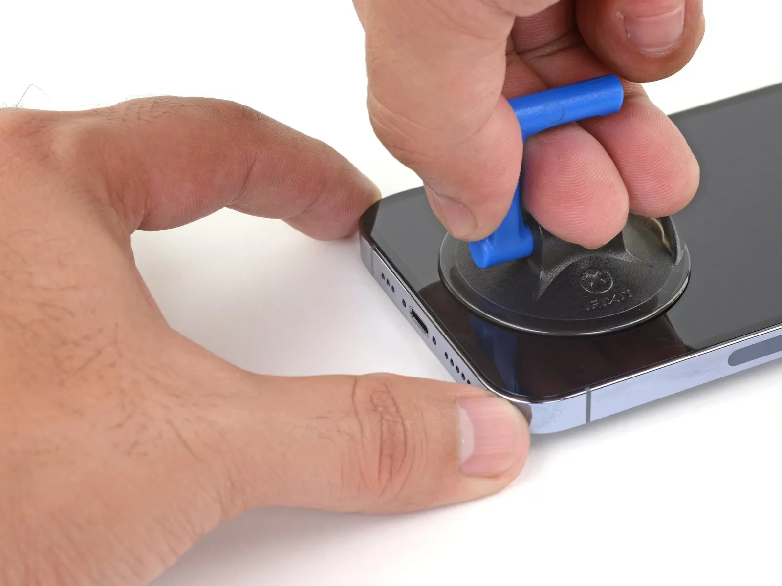
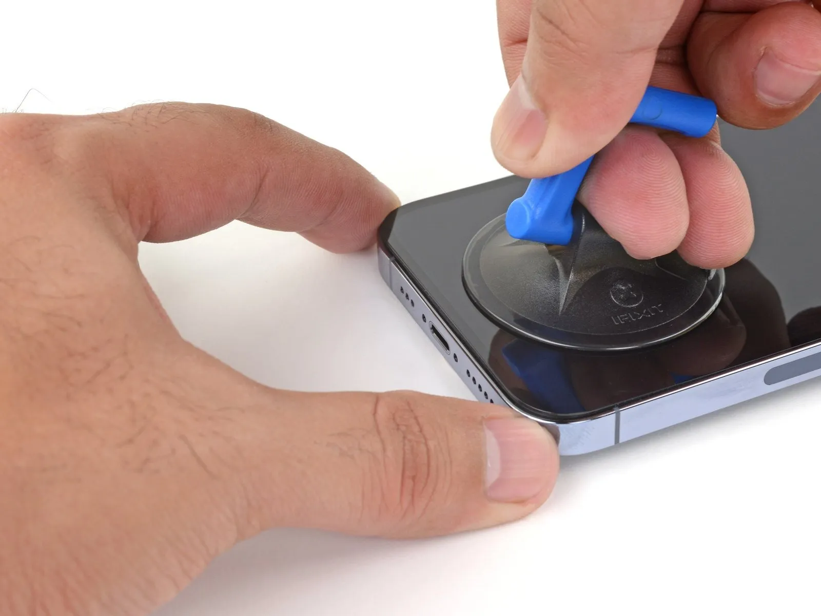
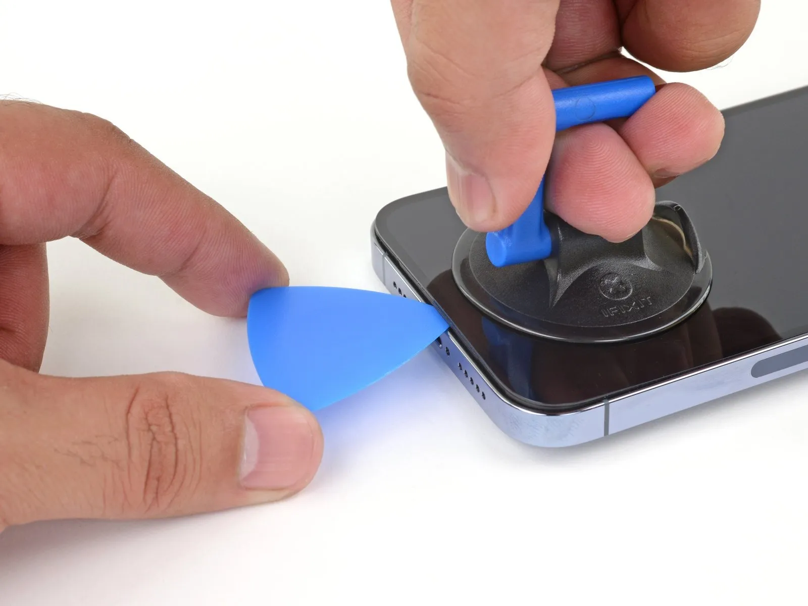
- Securely attach a suction handle to the lower perimeter of the device's casing, ensuring it remains clear of the screen's outermost glass boundary.
- Maintain consistent, substantial upward force on the suction cup to generate a minimal separation between the display assembly and the phone's structural frame.
- Carefully introduce an opening tool into the newly formed space located beneath the screen's surrounding plastic trim.
- The screen is secured by a robust waterproof sealant; overcoming this initial adhesion requires considerable effort; if separation proves difficult, apply additional heat and gently oscillate the display to reduce adhesive strength until a sufficient gap is achieved for tool insertion.
Step 9 | Heat the right edge


- Apply warmth to the right-hand perimeter of the iPhone's casing, encompassing the power button's location, utilizing a hair dryer for a duration of 90 seconds.The application of heat should continue until the surface temperature of the display becomes noticeably warm to the touch, indicating sufficient heating.This localized heating process facilitates separation of the screen assembly from the iPhone's frame by softening the adhesive.
Step 10 | Separate the right adhesive
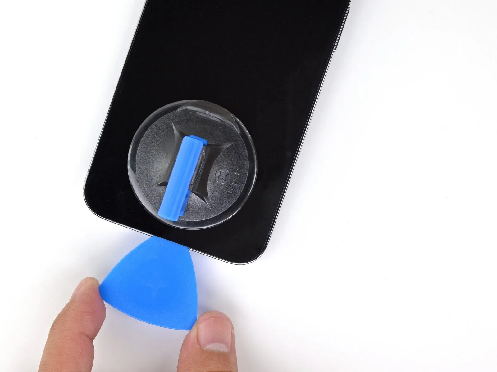
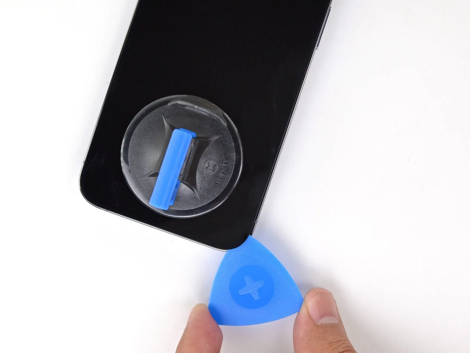
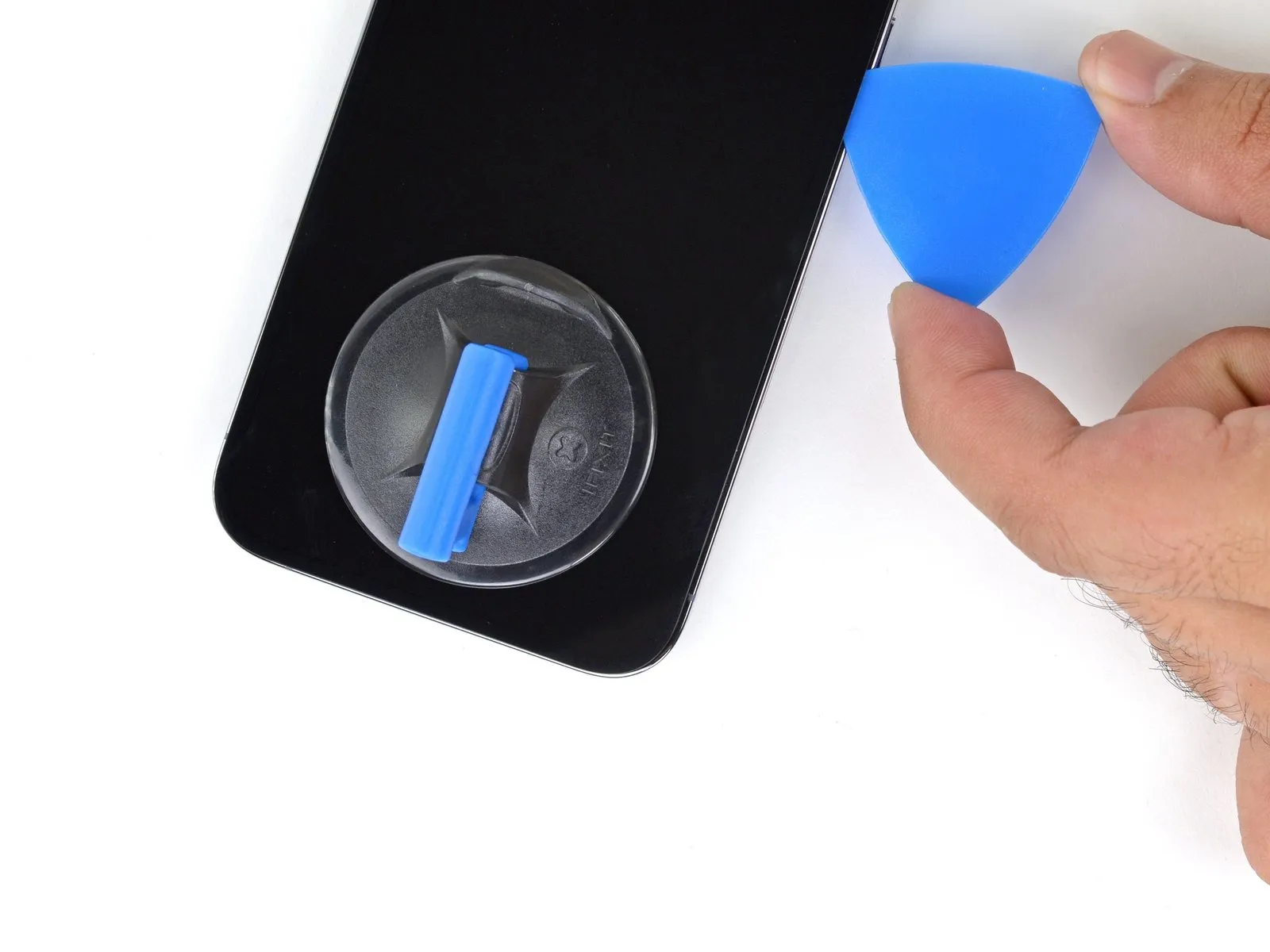
- Utilize a specialized opening tool to release the adhesive securing the iPhone's lower-right perimeter.
- Progress the tool's movement along the right side of the device's casing, advancing upwards until the upper-right corner is reached.
- Ensure the opening tool's insertion depth remains below a maximum of 3 millimeters to prevent potential harm to delicate internal parts.Maintaining the tool's position at the upper-right corner is necessary before proceeding with subsequent steps.The adhesive bond is released by carefully maneuvering the opening pick along the iPhone's lower-right section.
- To avoid internal component damage, restrict the opening tool's penetration to a depth not exceeding 3 mm.
Step 11 | Heat the top edge

- Apply warm air from a hair dryer to the iPhone's upper border, maintaining heat for a duration of 90 seconds, or until the surface reaches a temperature that is noticeably warm to the touch.The purpose of this heating process is to soften the adhesive securing the display assembly, facilitating its separation from the device's frame.Exercise caution during this step to avoid overheating the iPhone, which could potentially damage internal components.
Step 12 | Separate the top adhesive
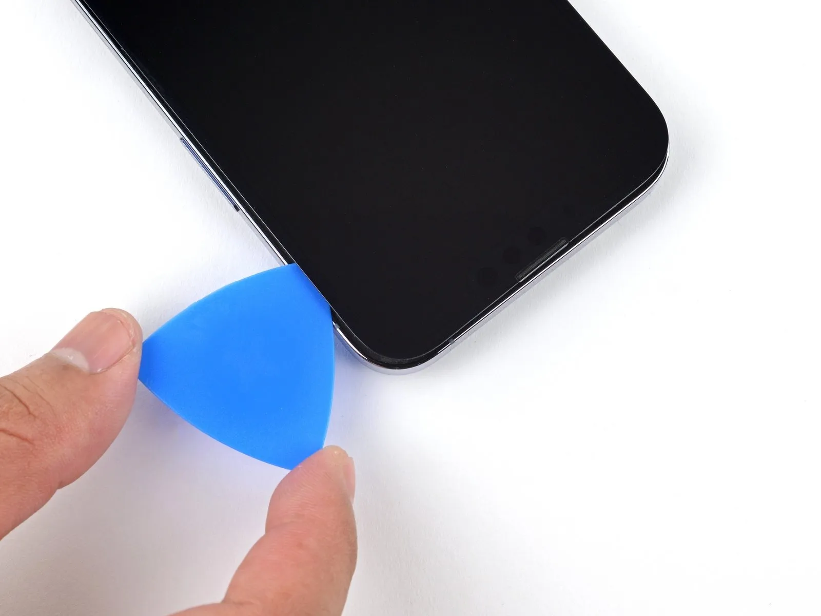
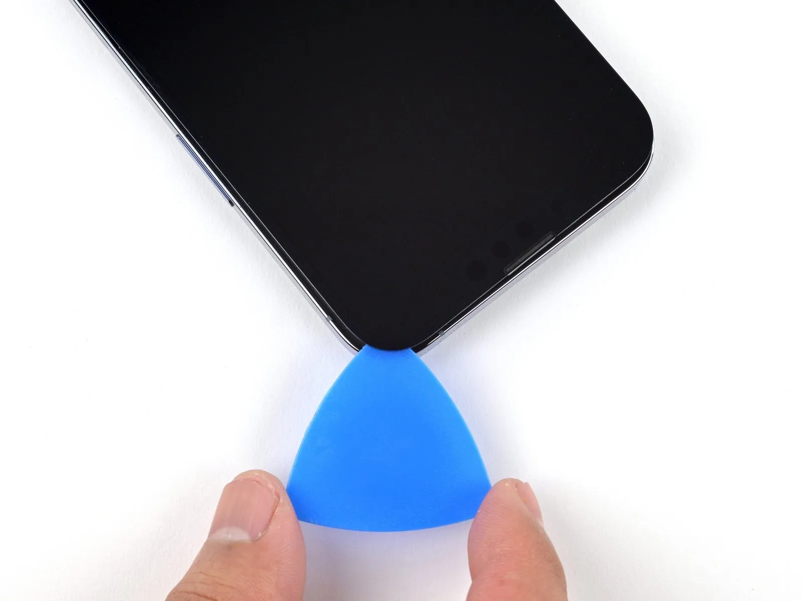
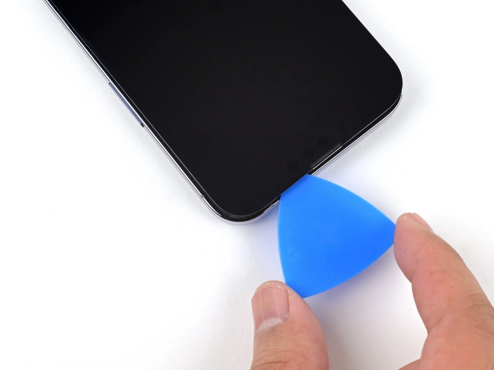
- Utilize a separation tool to carefully release the adhesive securing the iPhone's upper right edge.
Insertion depth of the separation tool must not exceed 3 millimeters to prevent potential harm to the proximity and other sensors located at the top.Maintaining the separation tool's position within the upper left corner is necessary prior to proceeding with the repair.The adhesive bond along the top edge of the iPhone requires careful separation using a specialized opening tool.
Exceeding a 3-millimeter insertion depth with the separation tool carries a risk of damaging the delicate sensor assembly situated near the top of the device.
Step 13 | Heat the left edge


Apply warm air from a hair dryer to the left side of the iPhone's enclosure, maintaining heat for 90 seconds, or until the surface temperature reaches a point where it is noticeably warm to the touch.The purpose of this heating process is to soften the adhesive securing the display assembly, facilitating its separation from the device's frame.Exercise caution during this step, as excessive heat can potentially damage internal components; avoid exceeding a temperature that is uncomfortable to briefly touch.
Step 14 | Screen information

Fragile wiring is situated along the iPhone's left side, necessitating caution during any intervention.Introducing a tool into this area carries a risk of inflicting harm upon the internal cables.Exercise care to prevent damage to the mentioned cables.
Step 15 | Separate the left adhesive
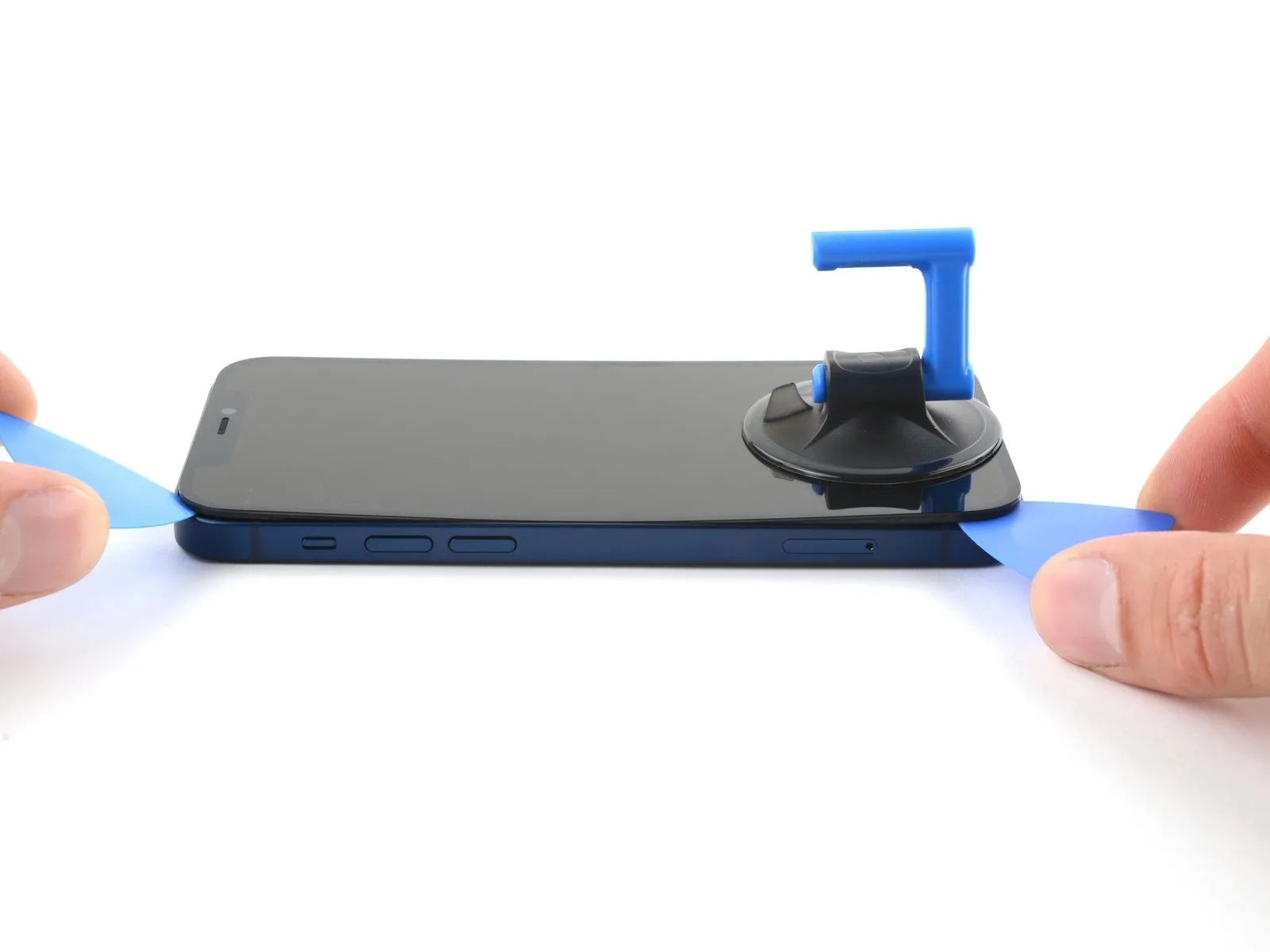
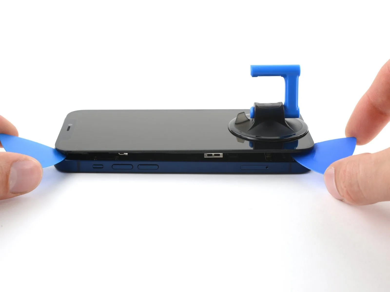
- Position a supplementary opening pick within the lower-left area of the iPhone's enclosure.
- Rotate both opening tools concurrently, exerting a twisting action to disengage the left-side clips.
- Implement the rotational force progressively to prevent damage.
- Should separation prove difficult, reapply heat to the left edge to soften the adhesive.
Step 16 | Open the iPhone

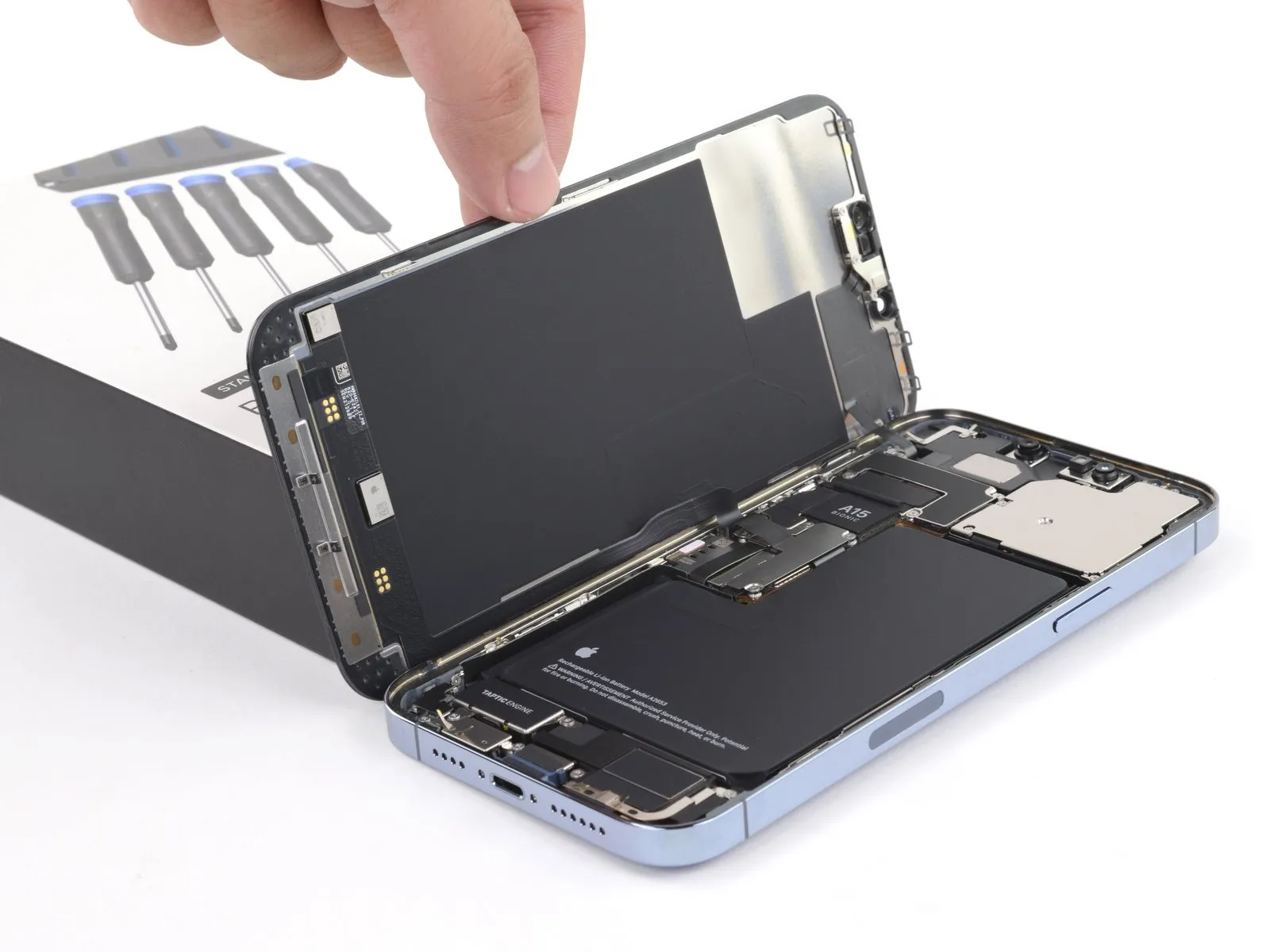
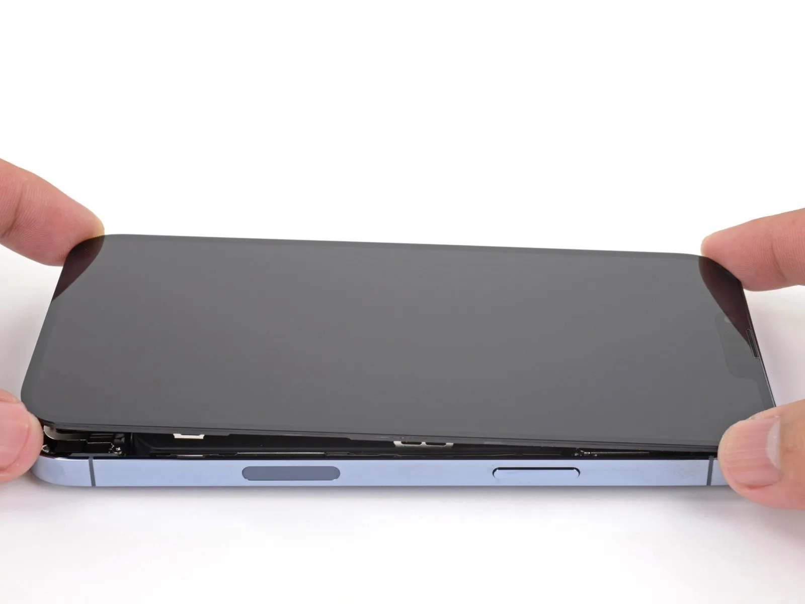
- Detach the suction handle from the display's surface.Orient your iPhone, positioning the right-hand side towards yourself.Initiate the iPhone's opening process by pivoting the display upwards from the right side, mimicking the action of opening a book's cover.
- Avoid complete separation of the display at this stage, as multiple delicate ribbon cables remain connected to the internal logic board.
- Secure the lifted display in an upright position using a support to maintain access to the internal components.
- When reassembling, position the display, ensuring the upper clips are aligned, and then gently apply pressure to the top edge before securing the remainder of the display.If the display does not readily seat, inspect the clips encircling the display's perimeter for any deformation.Confirm that the display clips are free from bends to facilitate proper closure.
- Ensure the clips are in good condition to guarantee a secure and even display attachment.
- Properly aligning and securing the display clips is essential for a successful reassembly.
Step 17 | Remove the battery connector cover

- Employ a Y000 screwdriver to detach the three 1.3 mm screws that hold the battery connector cover in place.Carefully monitor the location of each screw during disassembly, ensuring correct placement during reassembly to prevent potential damage to the iPhone.To verify proper functionality, briefly activate the iPhone and test all features at this stage of the repair process.Prior to securing the display, completely deactivate the iPhone to avoid any unintended consequences.The three screws, each measuring 1.3 mm, are fastened with a Y000 screwdriver to retain the battery connector cover.
- Maintaining precise screw placement is crucial to avoid inflicting harm to the iPhone’s internal components during the repair.
- A functional test of the iPhone's features should be performed while power is on, before the display is permanently reattached.
Step 18

To access the battery connector, detach the protective cover.
Step 19 | Disconnect the battery

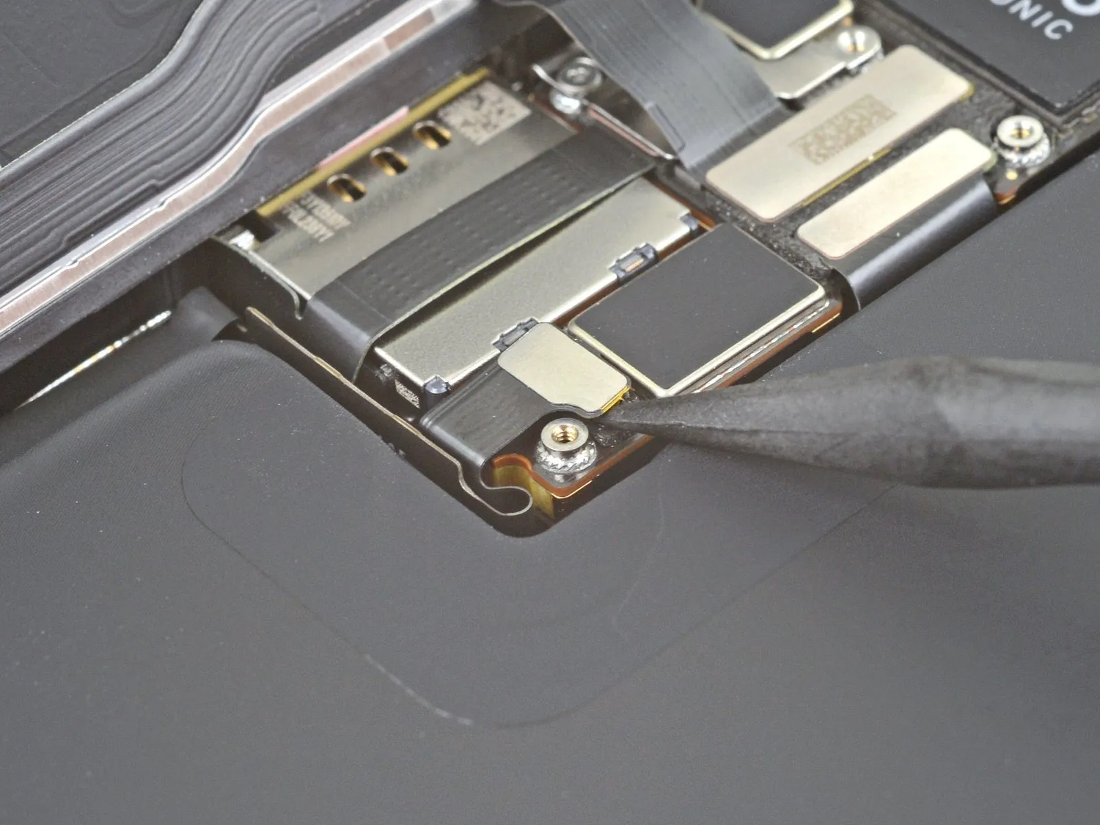
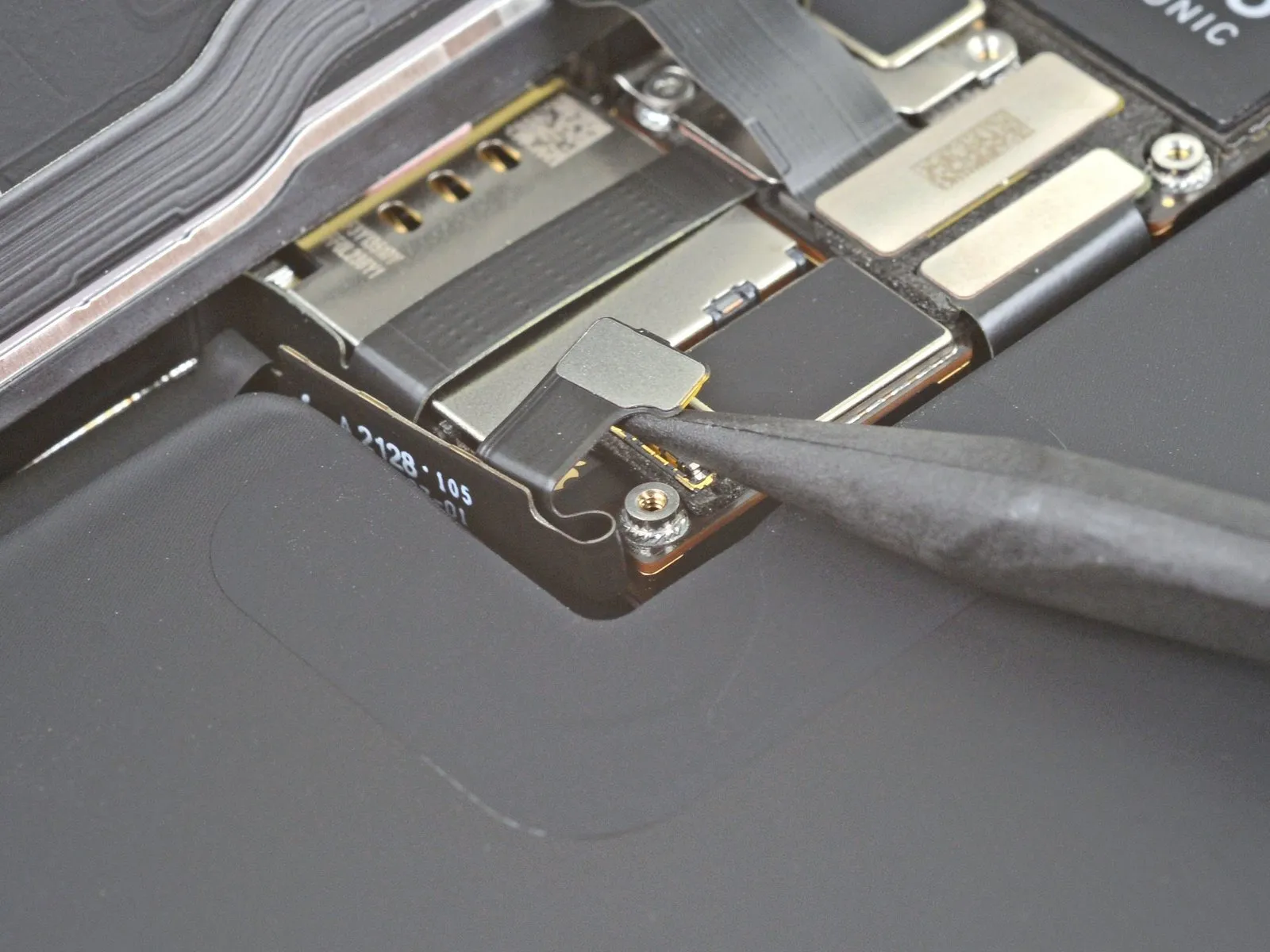
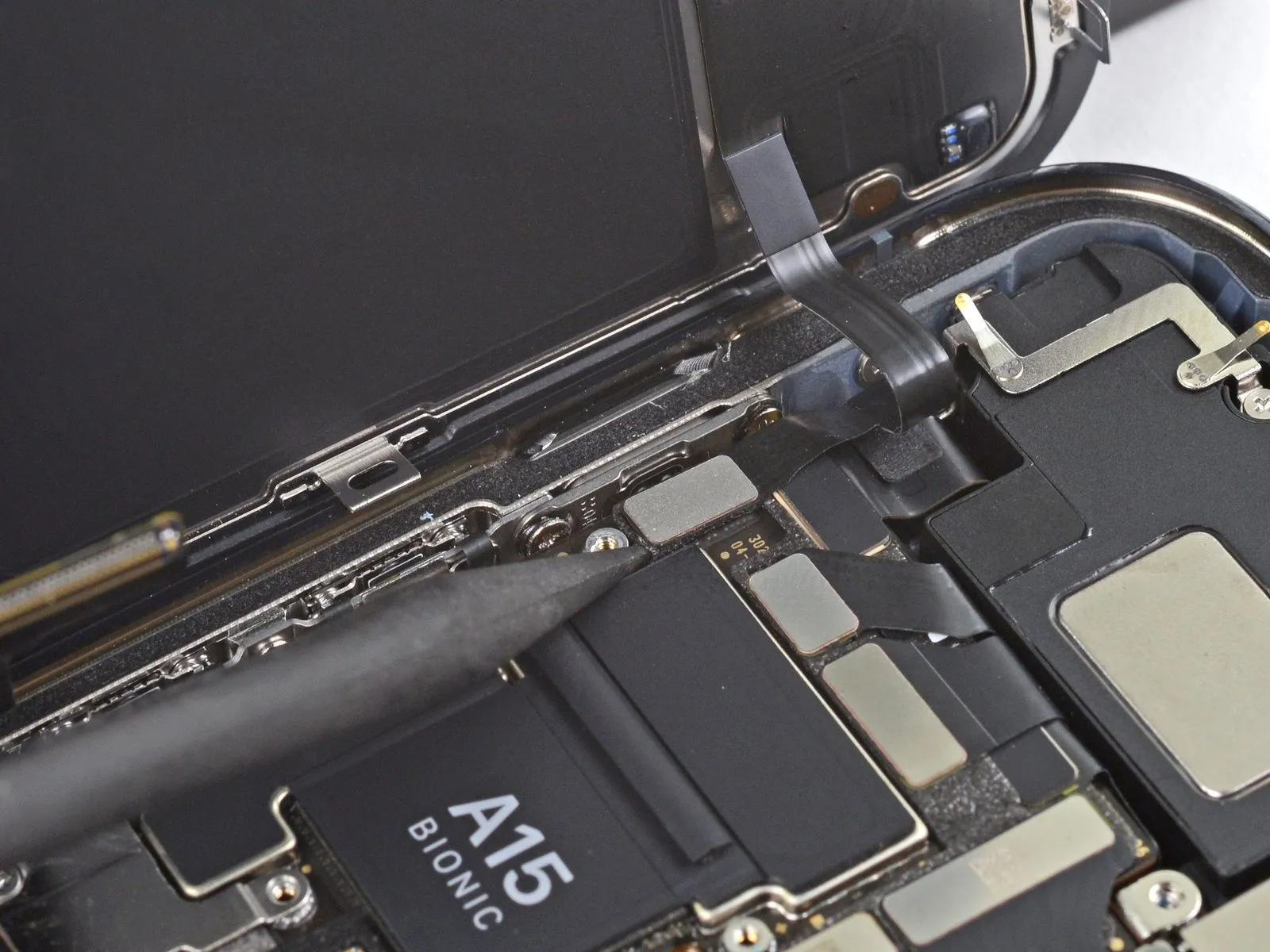
- Employ the tapered tip of a spudger or a pristine fingernail to elevate the battery connector's retaining clip from its corresponding receptacle on the logic board.Exercise caution to avoid harming the black silicone sealant that encases this and other circuit board connections, as it offers supplemental defense against water and particulate contamination.Slightly deflect the connector's orientation away from the logic board's surface to ensure it remains disconnected and prevents unintended power delivery to the device during the repair process.
- The silicone seals are crucial for maintaining the device's environmental resistance, so any damage could compromise its integrity.
- Careful manipulation of the battery connector is essential to prevent accidental short circuits and ensure a successful repair.
Step 20 | Disconnect the display cable

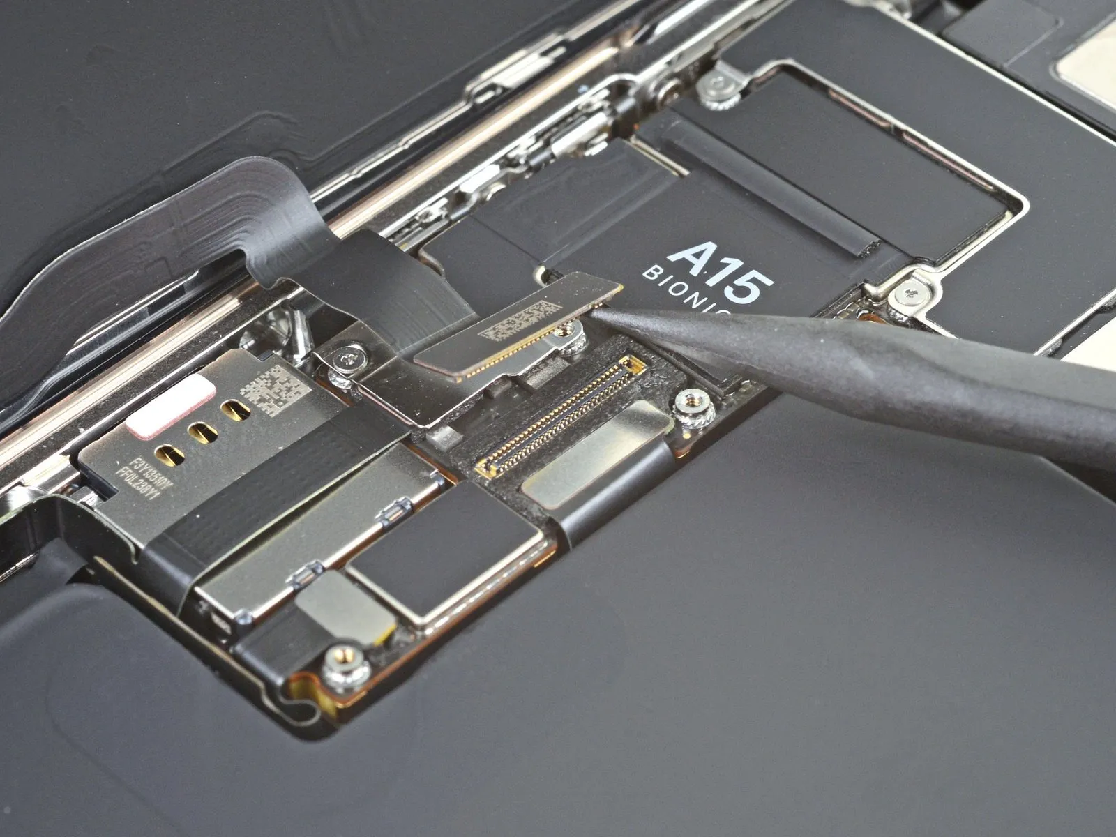
Employ a spudger's pointed tip, or a similarly shaped clean fingernail, to elevate the display connector away from its corresponding socket situated on the logic board.For reattachment, mirroring this procedure, meticulously align the connector and apply downward pressure to one edge until a distinct click is heard, subsequently repeating the process on the opposing edge.Avoid applying pressure to the central portion of the connector during reattachment to prevent potential damage.
- Misalignment during connector reattachment can result in pin deformation, potentially leading to irreversible component failure.
Step 21 | Unscrew the front sensor connector cover

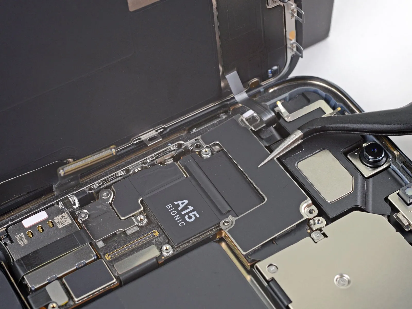
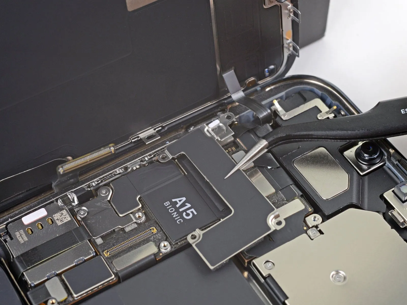
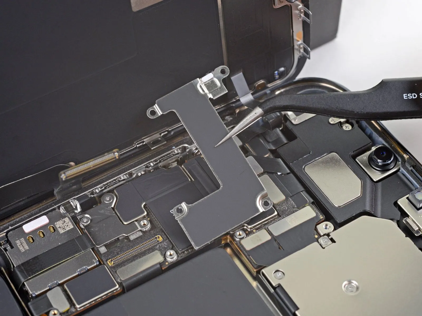
- Employ a Y000 screwdriver for the removal of the front sensor connector cover's two 1.1 mm screws.To detach the front sensor connector cover, utilize a Phillips screwdriver.The remaining fasteners securing the front sensor connector cover require removal with a Phillips screwdriver.A 1.5 mm screw is among the fasteners to be removed.Additionally, a 1.8 mm screw must be detached from the front sensor connector cover.
- The Y000 screwdriver is essential for disengaging the specified screws.Phillips screwdrivers are required for the subsequent steps in the disassembly process.Carefully extract the two 1.1 mm screws using the appropriate screwdriver.
- The front sensor connector cover is held in place by a combination of screw types.Ensure that the Phillips screwdriver is correctly engaged with the screw heads to prevent damage.
- The 1.5 mm screw and 1.8 mm screw contribute to the secure attachment of the cover.Proper tool selection, specifically a Y000 and Phillips screwdriver, is crucial for successful disassembly.
Step 22
Step 23
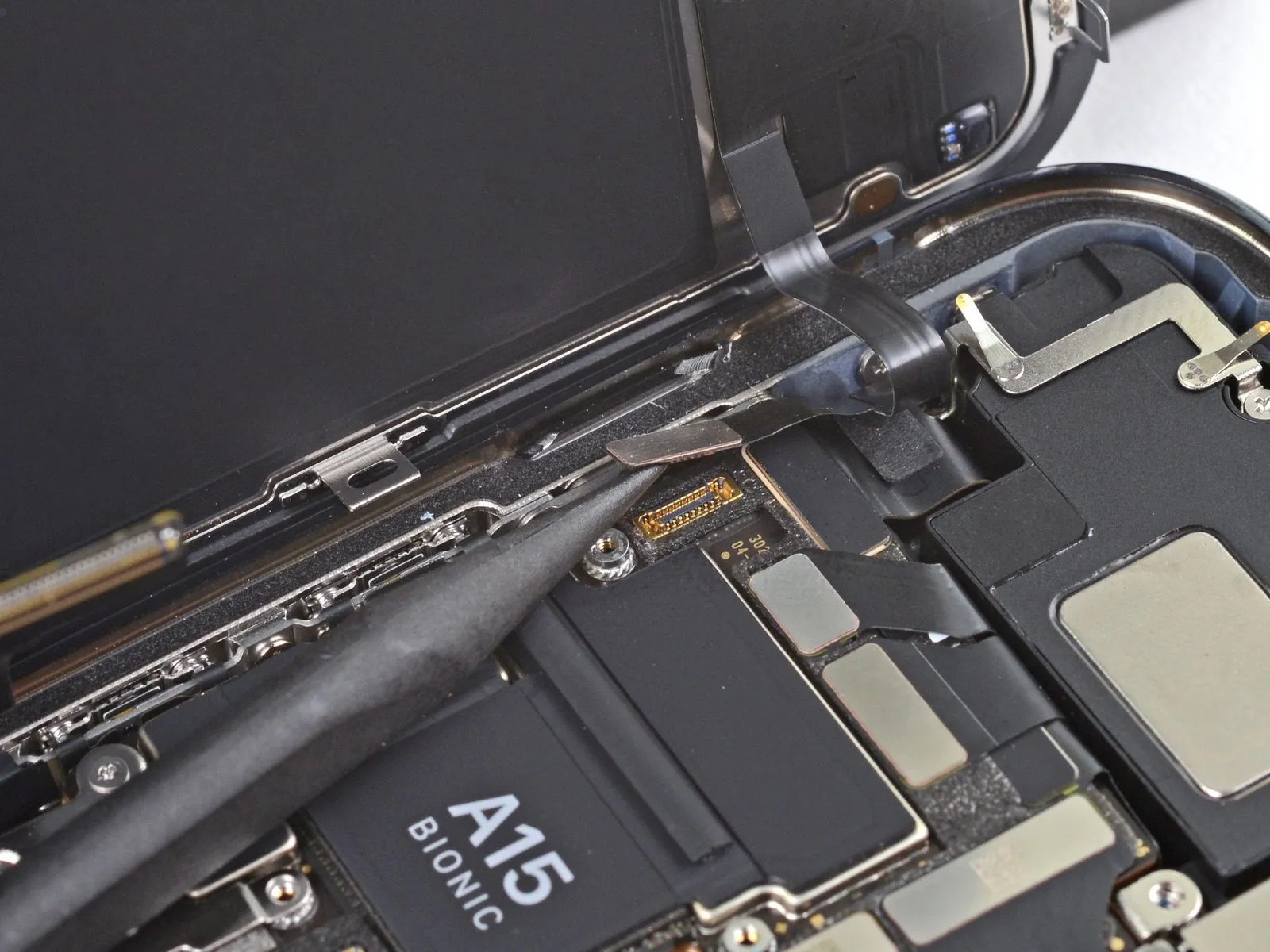
Step 24
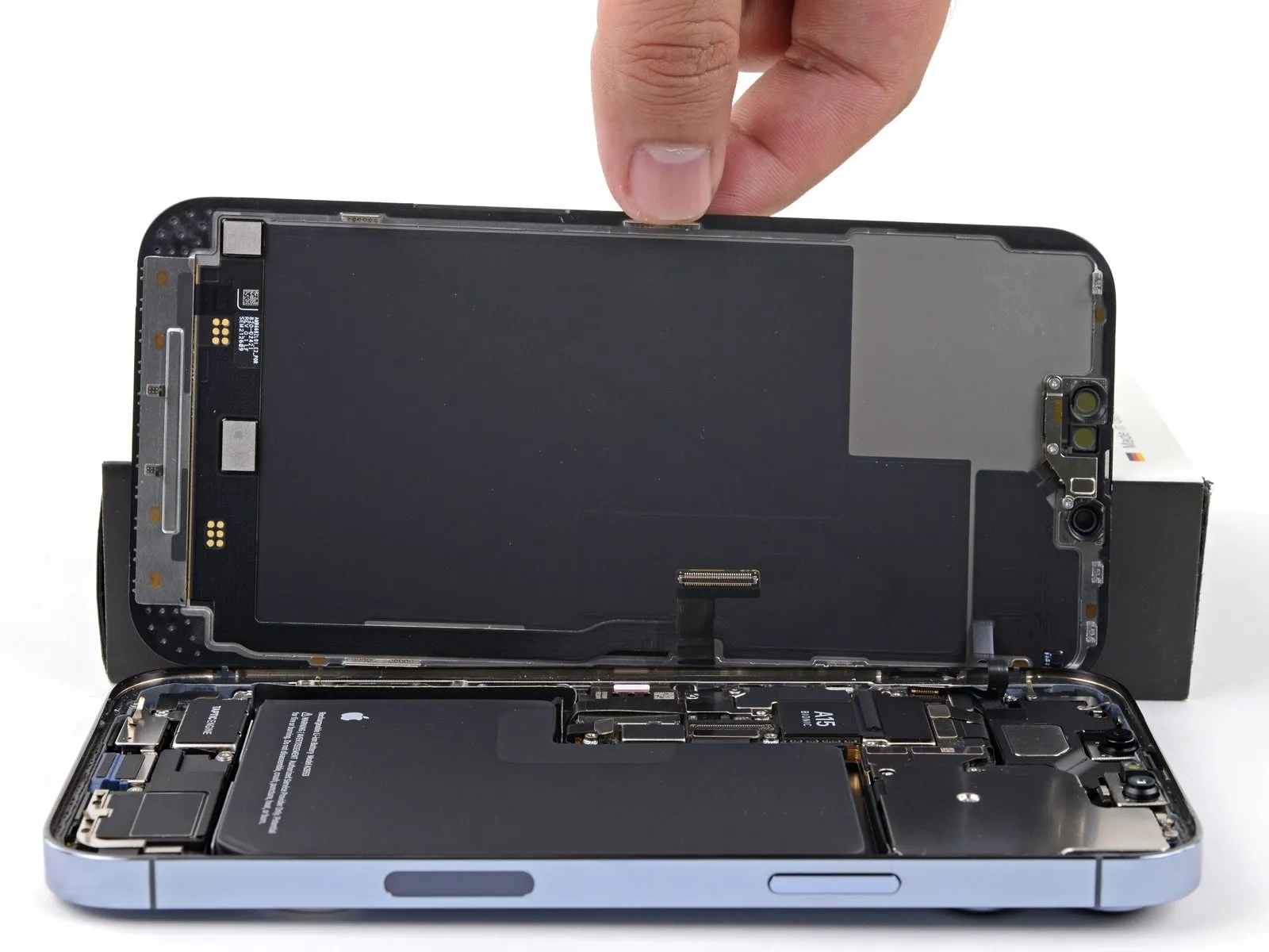
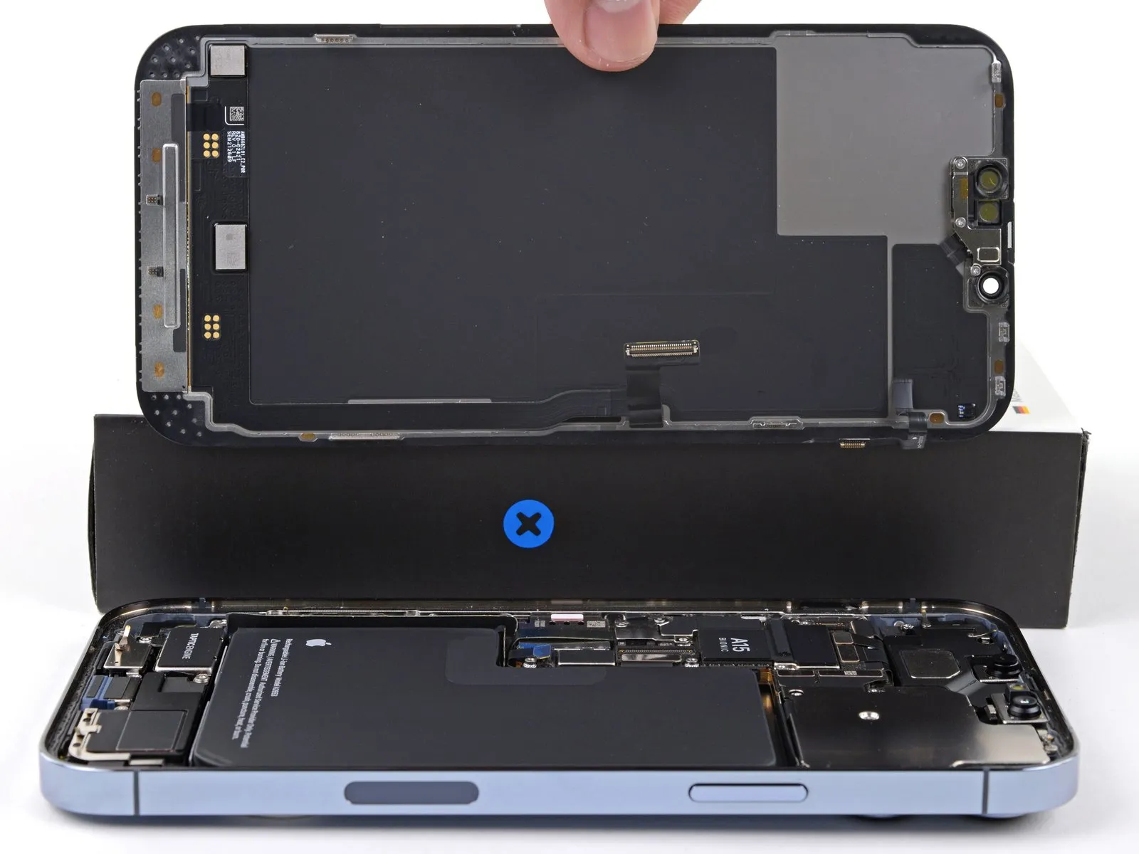
- Detach the display unit from the device.
- If a replacement of the waterproof adhesive seal bordering the display is desired, halt the reassembly process at this point.
Step 25 | Transfer the adhesive-backed strip
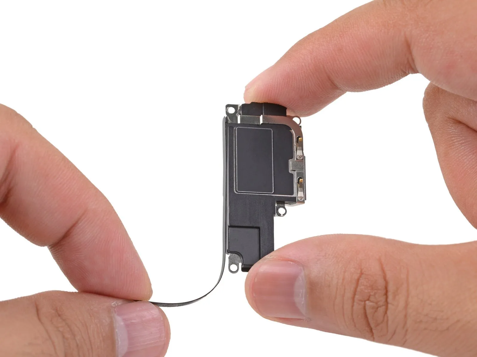
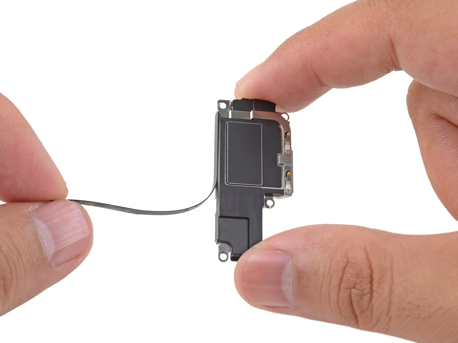
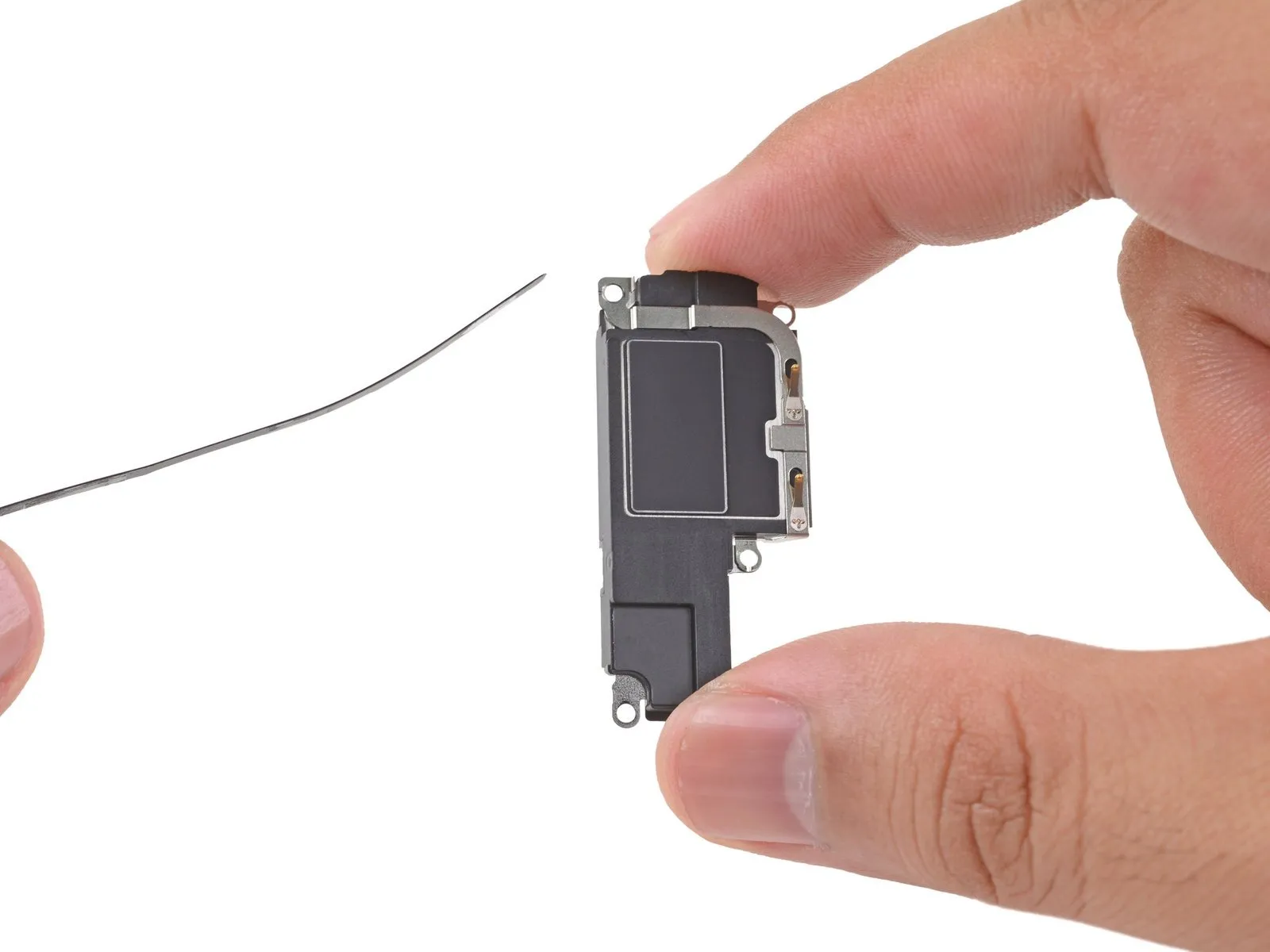
- Employing manual dexterity, carefully detach the adhesive-backed strip from the loudspeaker's surface.
Step 26
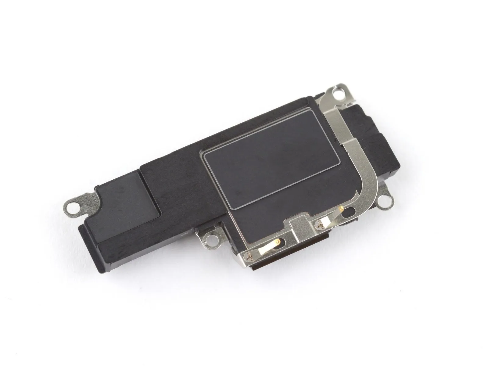
Step 27 | Remove the Taptic Engine
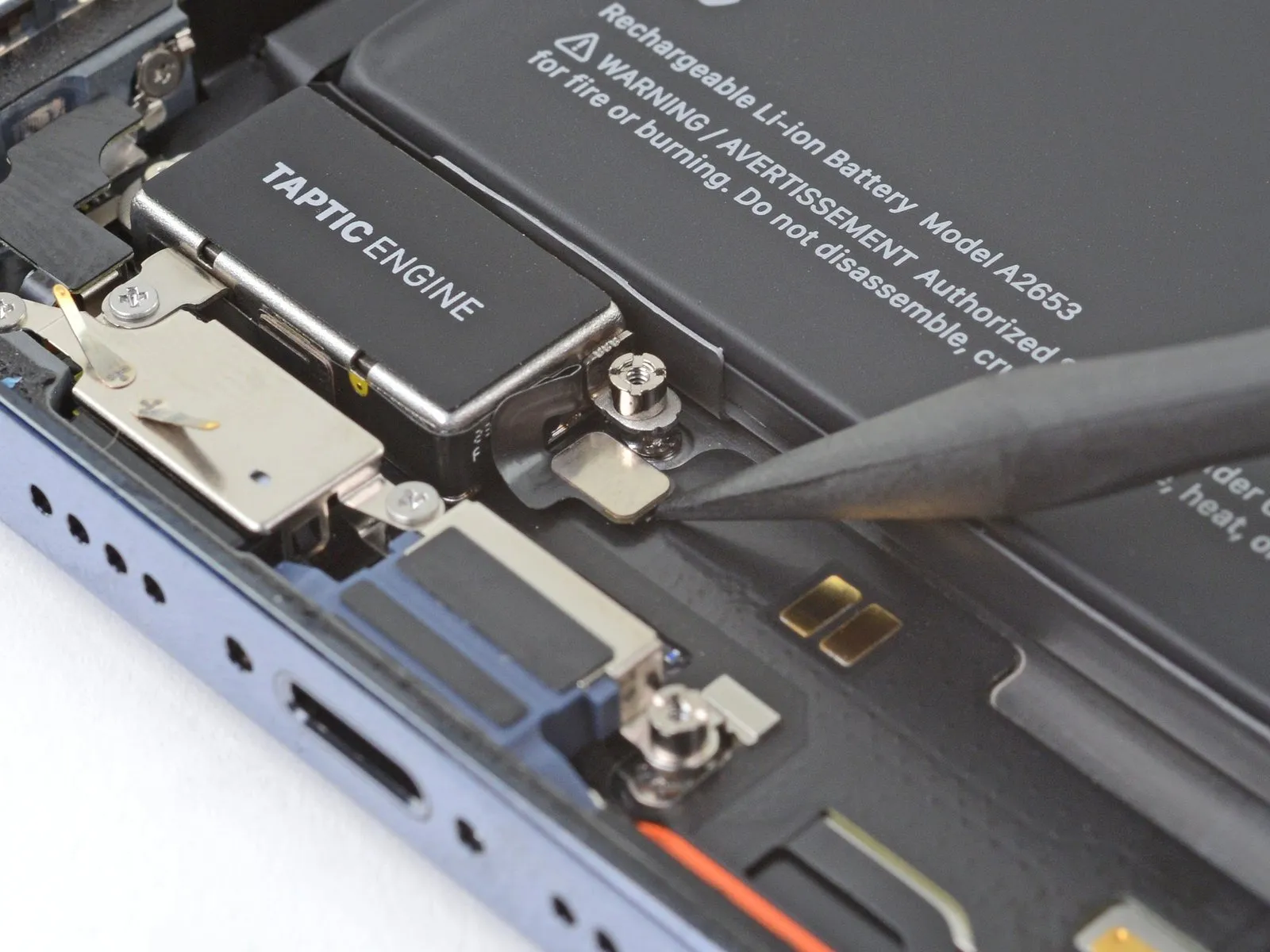
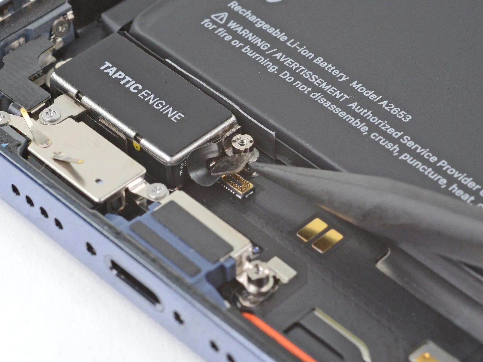
Step 28
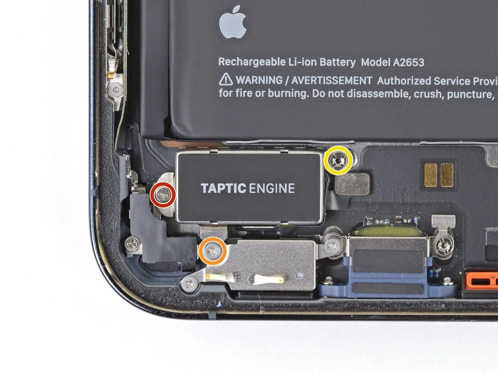
- Employ a Phillips screwdriver for disassembly.These screws fasten the Taptic Engine in place.
- A single screw with a 1.8-millimeter head is required.
- Additionally, a 1.9-millimeter screw is present.
- Utilize a standoff screwdriver for the subsequent step.This tool is needed to extract the fastener.The standoff screw measures 2.9 millimeters in diameter.This screw provides stability for the Taptic Engine.
Step 29
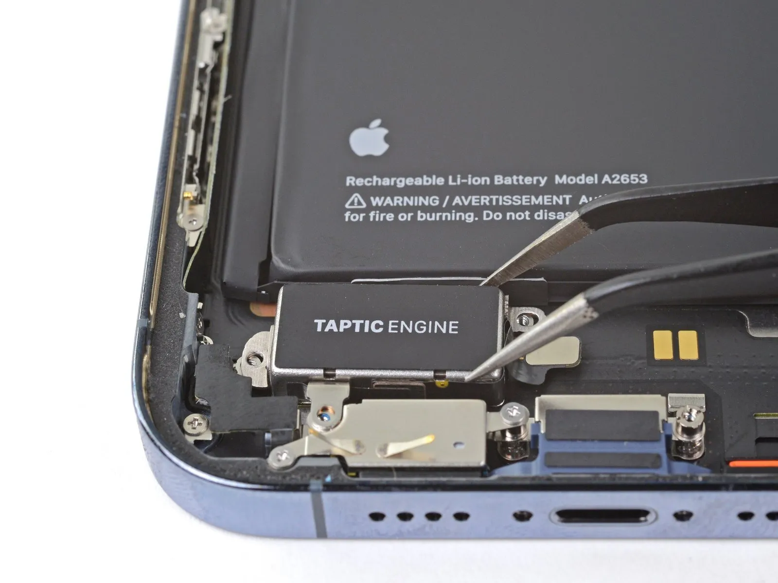
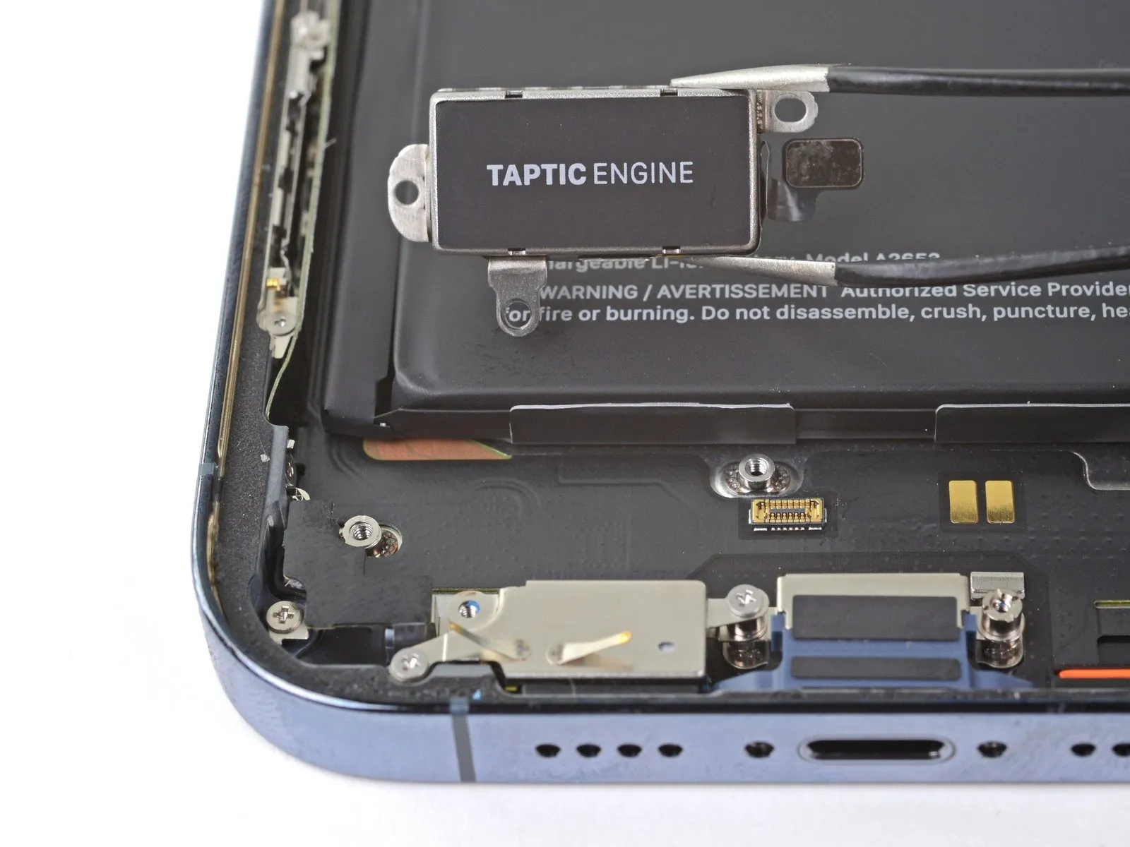
- Carefully detach the Taptic Engine component.The Taptic Engine must be disconnected for further servicing.Disassembly of the Taptic Engine requires meticulous attention to detail.