iPhone 14 Earpiece Speaker Replacement
This document details the process for removing or substituting the earpiece speaker component within an iPhone 14.
The instructions were developed referencing the A2882 iPhone 14 variant (intended for international markets); while minor visual differences might exist with other iPhone 14 models, the repair steps remain consistent.
- To ensure proper screen reattachment and maintain device sealing during reassembly, a fresh adhesive strip is required.
Following this repair, the iPhone 14 will operate as expected; however, the device's water and dust resistance (IP rating) will likely be compromised.
Step 1 | Remove the pentalobe screws
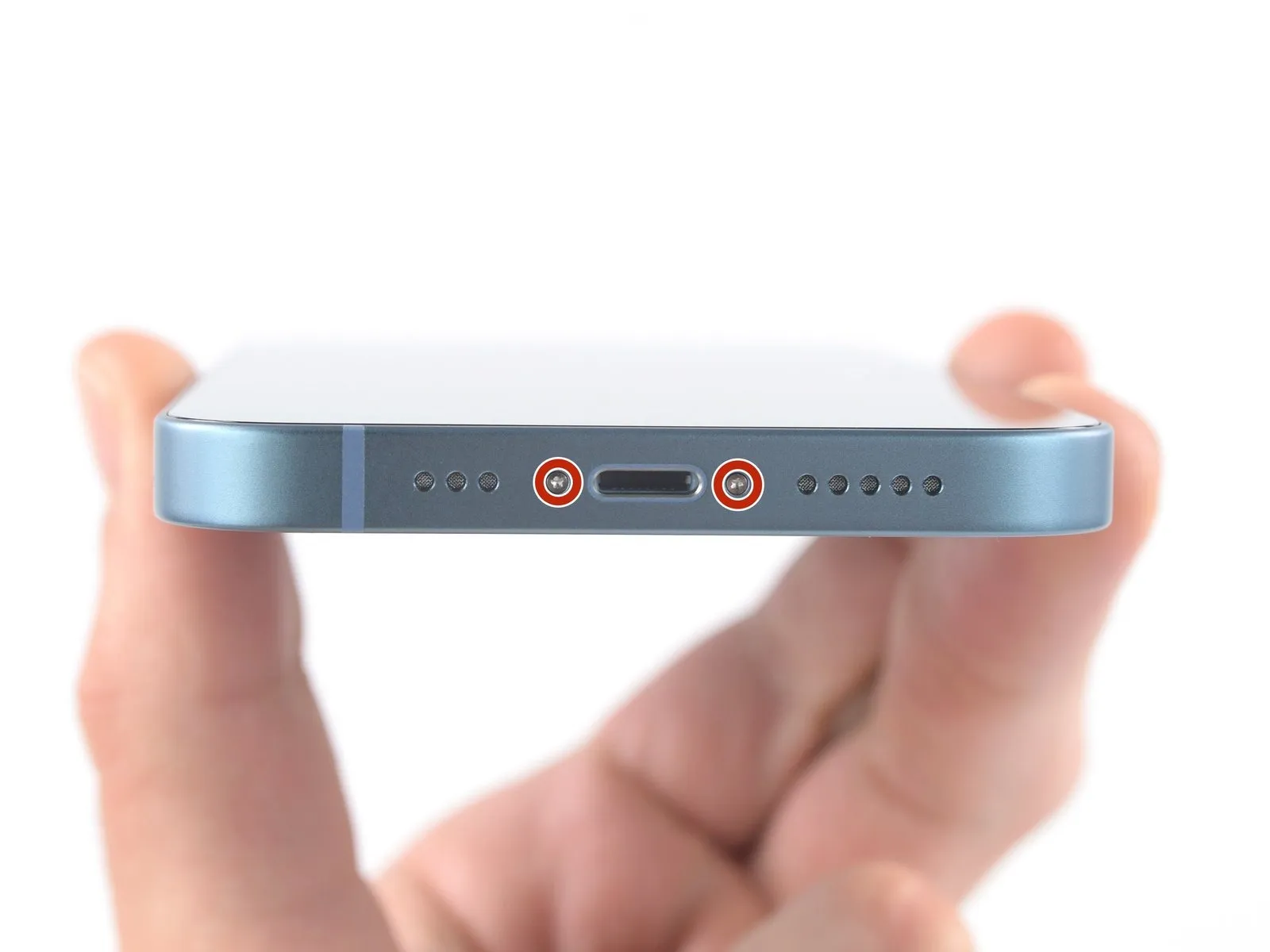
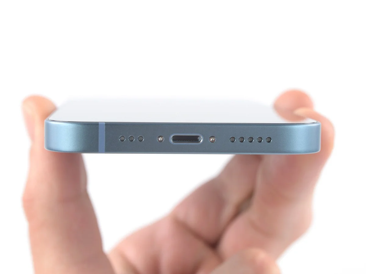
- Prior to commencing the iPhone's disassembly process, ensure the device is completely powered down.
- The process requires the removal of two screws, each measuring 6.8 millimeters in length, which are located along the iPhone's lower border.These screws are of the pentalobe P2 type, necessitating a compatible driver for their extraction.Carefully unscrew and retain these fasteners to prevent loss during subsequent repair steps.
Step 2 | Mark your opening picks


- To avert potential harm to your device, ensure the opening pick isn't inserted beyond its intended depth; this procedure details how to mark the pick to avoid such damage.
Using a measuring tool, determine a distance of3 mmfrom the pick's tip and use a permanent marker to create a visible indication. - For enhanced precision, consider marking the pick's other corners with varying measurement distances.
- As an alternative method, affix a coin to the pick's shaft, positioning it3 mmfrom the tip to serve as a depth gauge.
Step 3 | Tape over any cracks


- To mitigate additional damage and potential injury while repairing a rear glass fracture on your iPhone, secure the broken area with adhesive tape.
Completely cover the iPhone's rear glass surface by applying multiple, overlapping layers of transparent packing tape. - Protect your vision by utilizing safety eyewear, as shards of glass may become dislodged during the repair process.
- Should the suction cup fail to maintain adhesion during subsequent steps, create a handle by folding a durable tape, like duct tape, and employ it to elevate the rear glass.
- As a last resort, secure the suction cup directly to the rear glass using superglue to facilitate lifting.
Step 4 | Heat the bottom edge

- Apply warmth to the lower perimeter of the iPhone’s casing utilizing a hair dryer or heat gun, ensuring the rear glass panel reaches a temperature just beyond comfortable touch.
Avoid prolonged, concentrated heat application with the heat gun to prevent damage.
Step 5 | Insert an opening pick
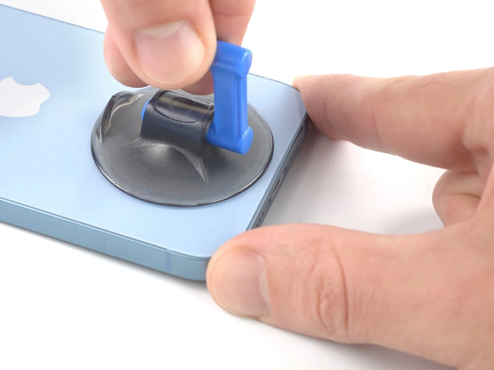
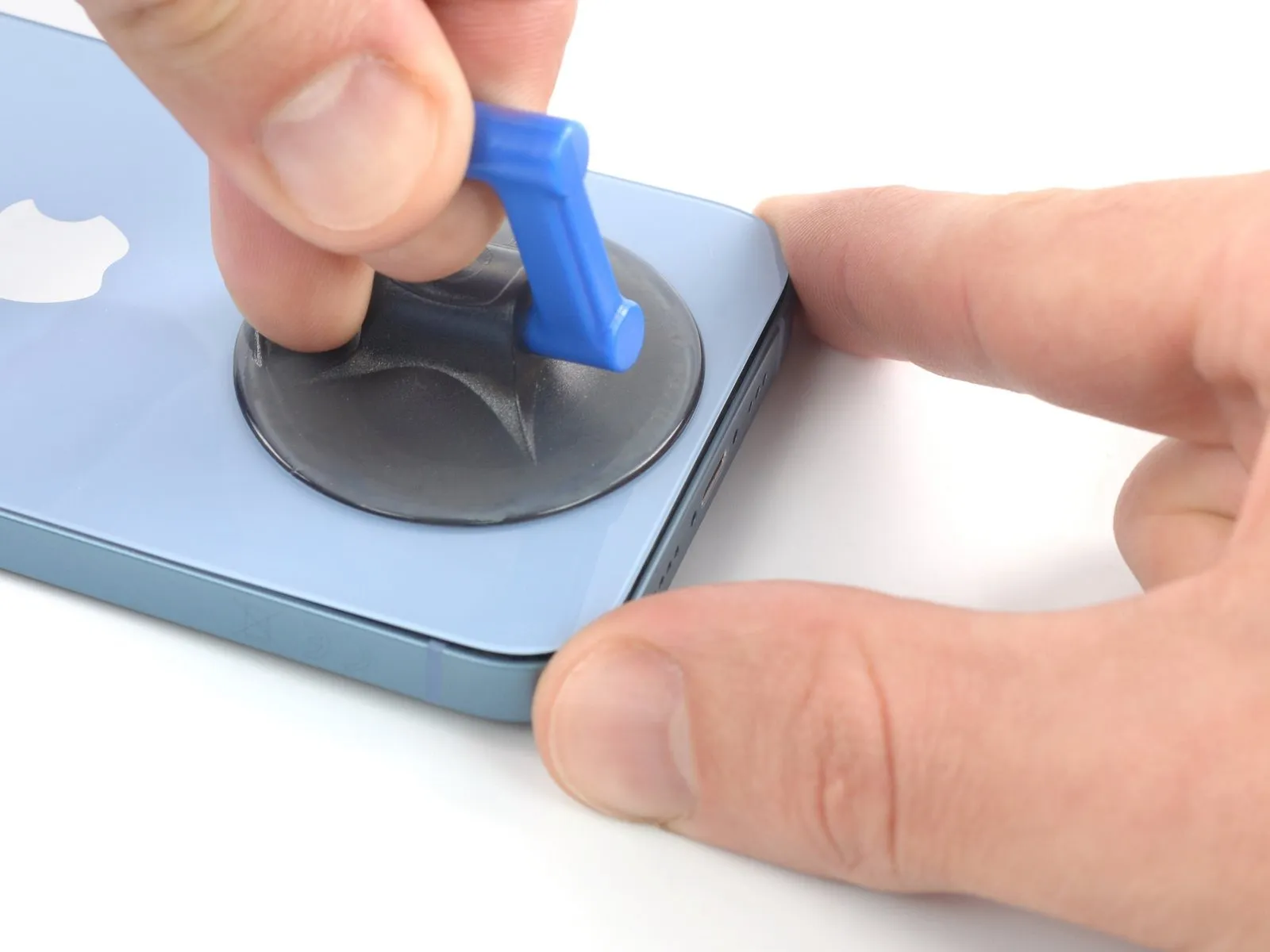
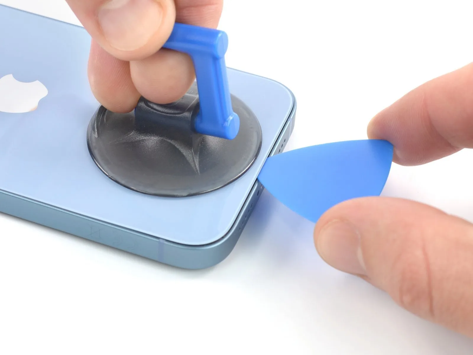
- Secure a suction handle to the lower perimeter of the back glass, ensuring you maintain clearance from the glass's extreme boundary.
- Maintain consistent, substantial upward force on the suction cup to generate a minimal separation between the rear glass and the device's housing.
- Introduce an opening tool into the newly formed space.
- Due to the robust nature of the adhesive securing the rear glass, considerable force is necessary to initially separate the glass; if separation proves difficult, apply additional heat and gently oscillate the rear glass to reduce adhesive strength until a sufficient gap is achieved for opening tool insertion.
Step 6 | Heat the left edge

To facilitate separation, apply heat to the left side of the iPhone's enclosure, raising the temperature of the rear glass to a point just beyond comfortable touch.
Step 7 | Slice the left edge adhesive
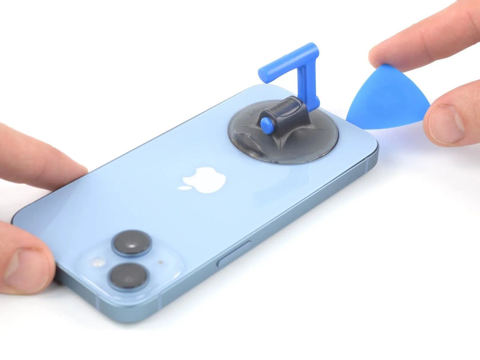
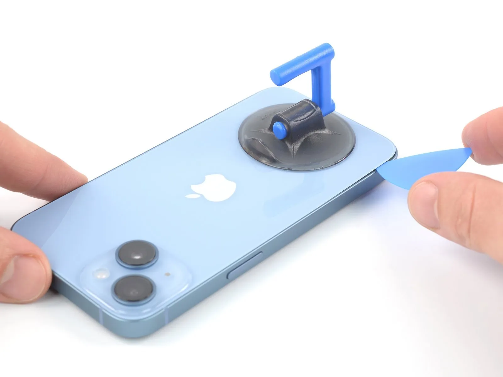
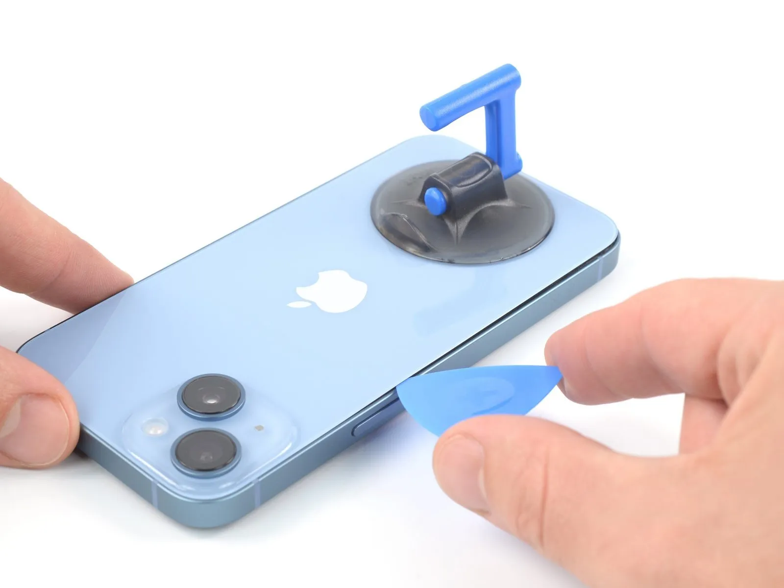
- Employ the opening pick to maneuver along the lower-left perimeter of the iPhone's casing, progressing upwards along the left side to sever the adhesive securing the rear glass assembly.
- Ensure the pick's insertion depth remains below 3 mmto prevent potential harm to the device's delicate internal components.
Step 8 | Rear glass information

A fragile wiring harness is situated near the upper-right perimeter, adjacent to the volume increase button; avoid inserting any tools in this area to prevent potential harm.The aforementioned wiring harness is susceptible to damage from improper handling.Exercise caution to protect the cable during the repair process.
Step 9 | Heat the right edge

Apply warmth to the right-hand side of the iPhone's casing, specifically the perimeter containing the volume controls, until the temperature of the rear glass reaches a level just beyond comfortable touch.The targeted area for heating is the right edge of the iPhone, identifiable by the presence of the volume buttons.Achieving a temperature slightly beyond the threshold of comfortable touch on the rear glass indicates sufficient heat application.
Step 10 | Slice the right edge adhesive
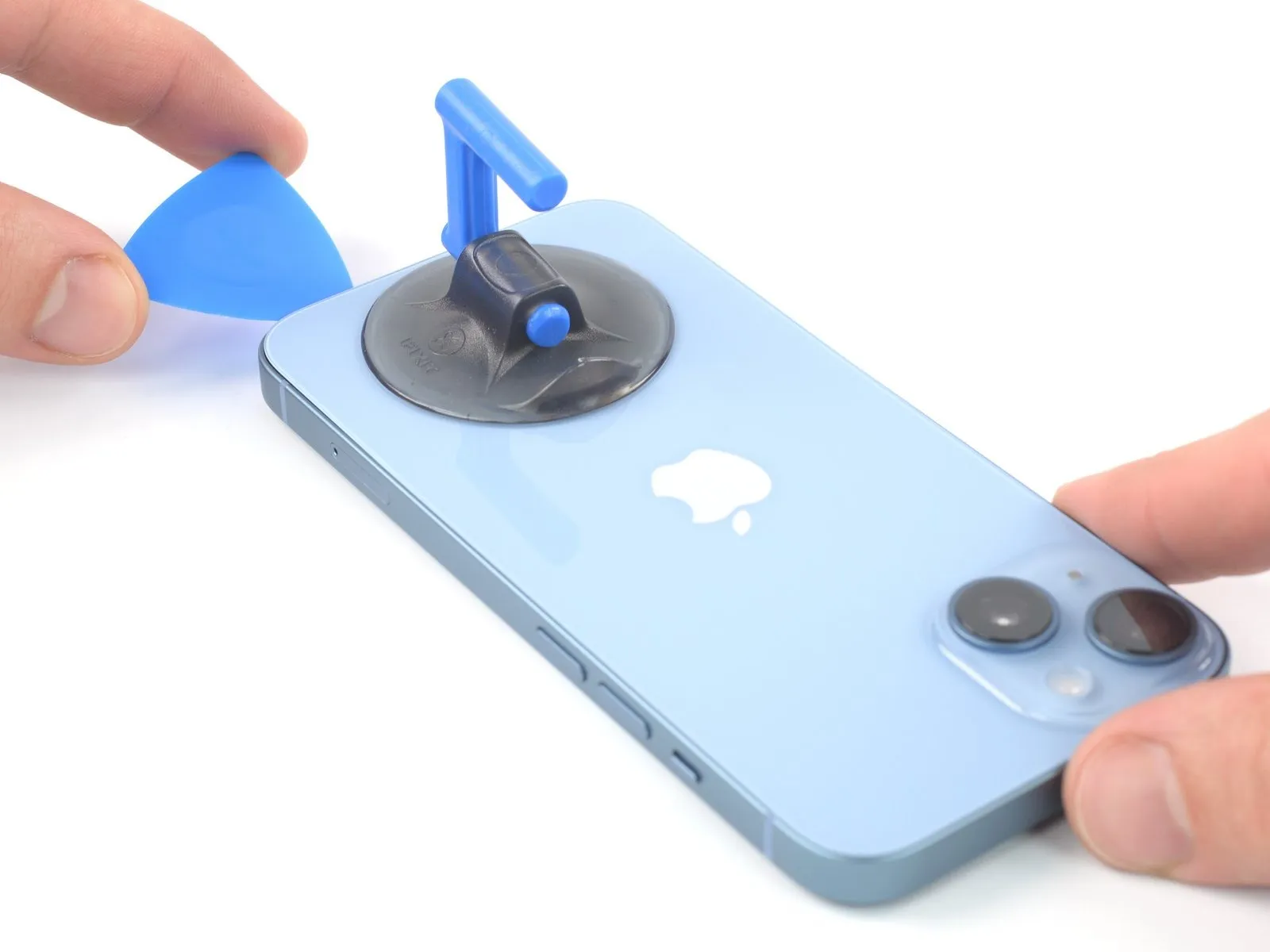
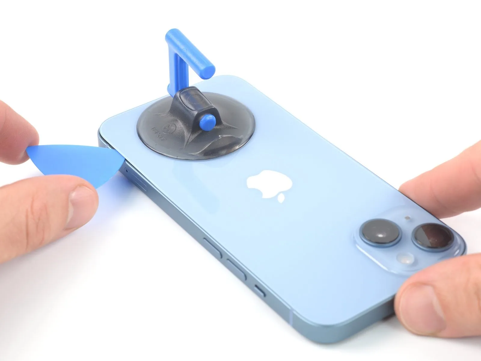
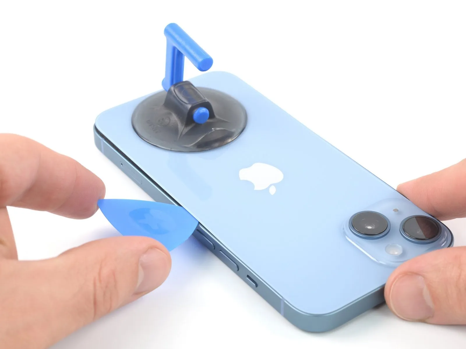
- To proceed with separating the adhesive, reposition your opening tool along the lower edge of the iPhone's enclosure and advance it upwards along the right side.
- Ensure the opening tool does not penetrate beyond a depth of 3 millimeters to prevent potential harm to the charging coil cable.Exceeding this 3-millimeter limit carries a risk of damaging the delicate charging coil cable.Maintaining a shallow insertion depth of no more than 3 mm is crucial for safeguarding the charging coil cable during separation.
Step 11 | Heat the top edge

Apply warmth to the upper portion of the iPhone's casing, ensuring the back glass reaches a temperature just beyond comfortable touch.Localized heating of the iPhone's top edge is necessary to facilitate rear glass separation, with a target temperature slightly above the threshold of comfortable skin contact.To loosen the adhesive securing the rear glass, use heat to raise the temperature of the iPhone's upper edge to a point where it becomes noticeably warm to the touch.
Step 12 | Slice the top edge adhesive
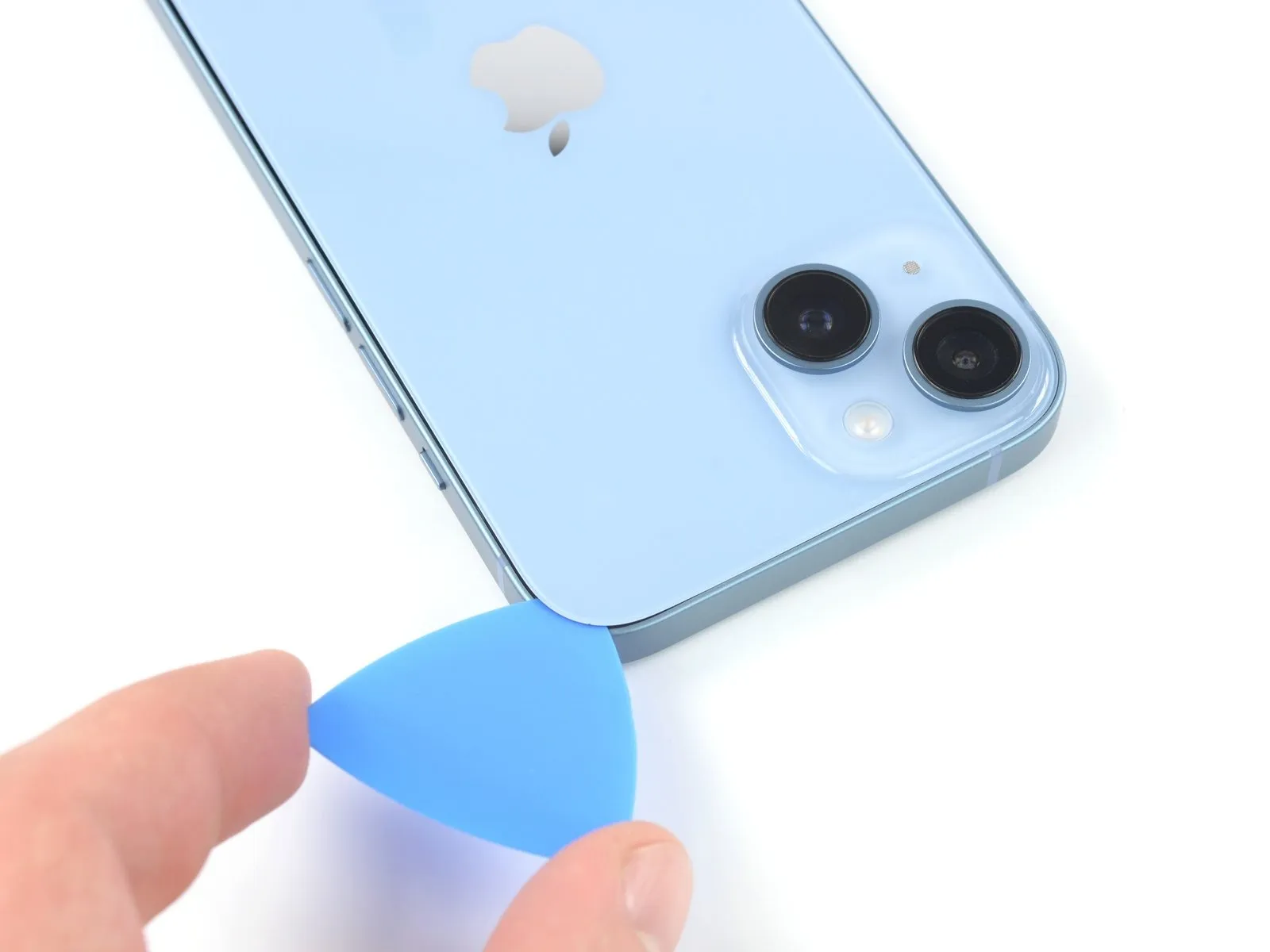
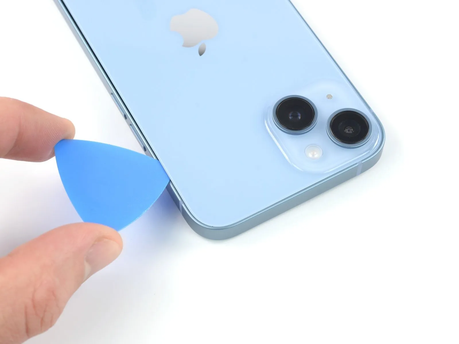
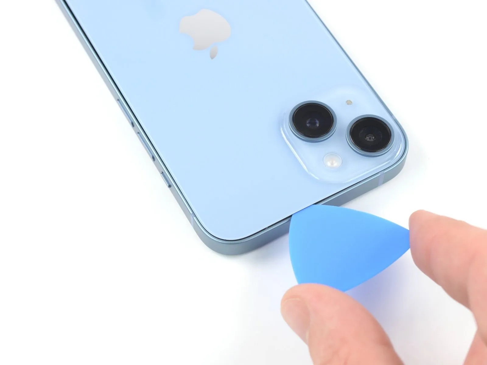
Position a prying tool beneath the uppermost right corner of the device's casing.Carefully move the tool along the top-right contour and advance it to the midpoint of the upper edge.This action initiates separation of the enclosure.
Step 13
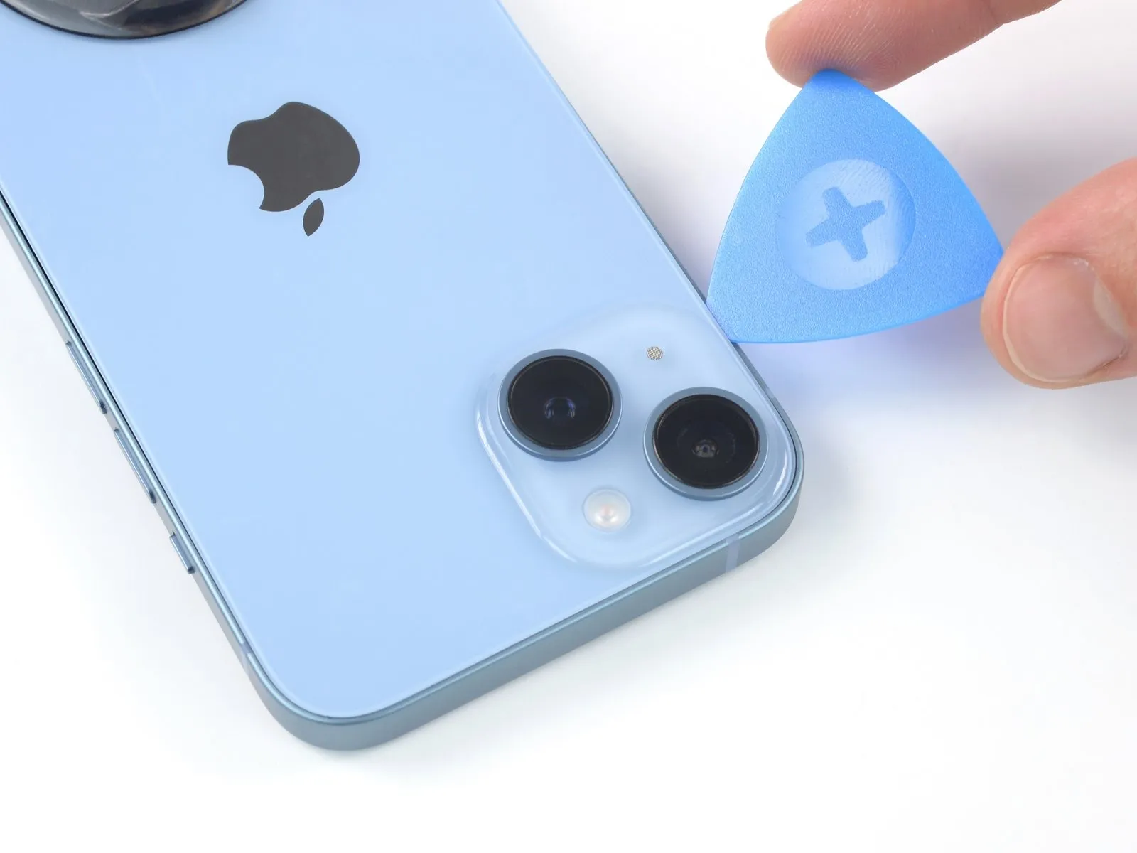
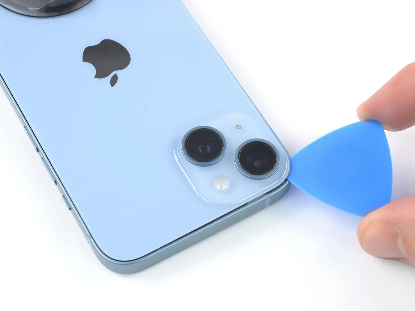
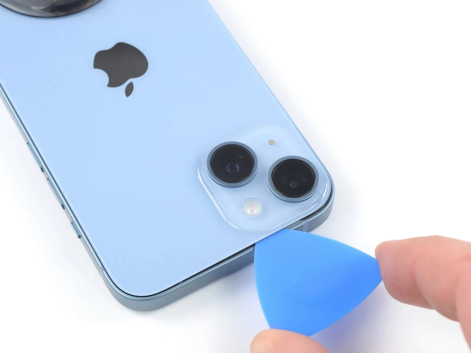
- Position a specialized opening tool beneath the upper-left corner of the device's casing.
- Maneuver the tool along the top-left contour and across the top edge to approximately the midpoint.Limit insertion depth to a maximum of 3 millimeters to prevent potential harm or distortion of the camera module.Refrain from attempting a complete separation of the rear glass panel at this stage, because a delicate flexible connector remains linked to the iPhone's main circuit board.
- The ribbon cable's fragility necessitates a staged separation process to avoid unintended disconnection.
Step 14 | Open the iPhone
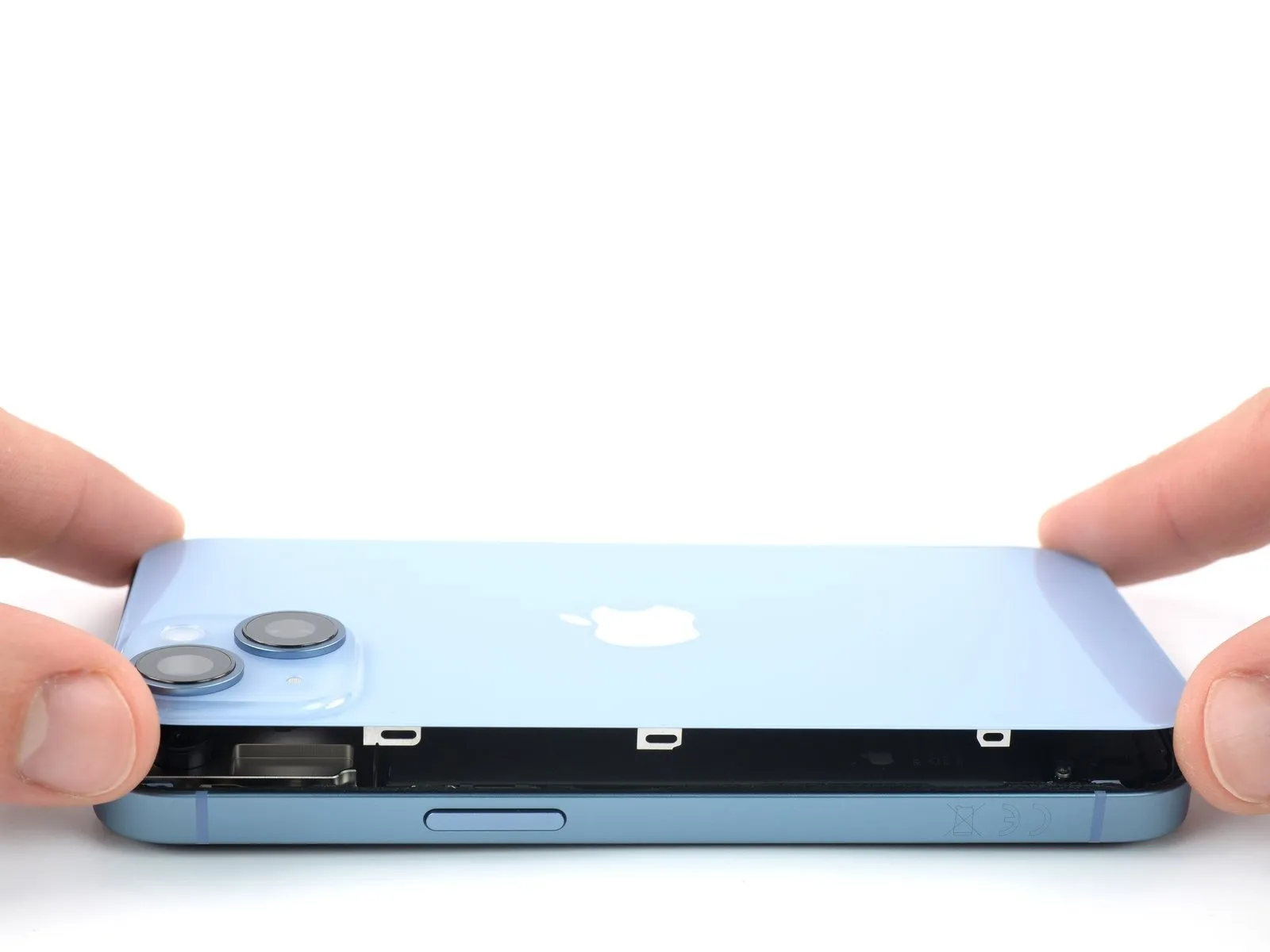
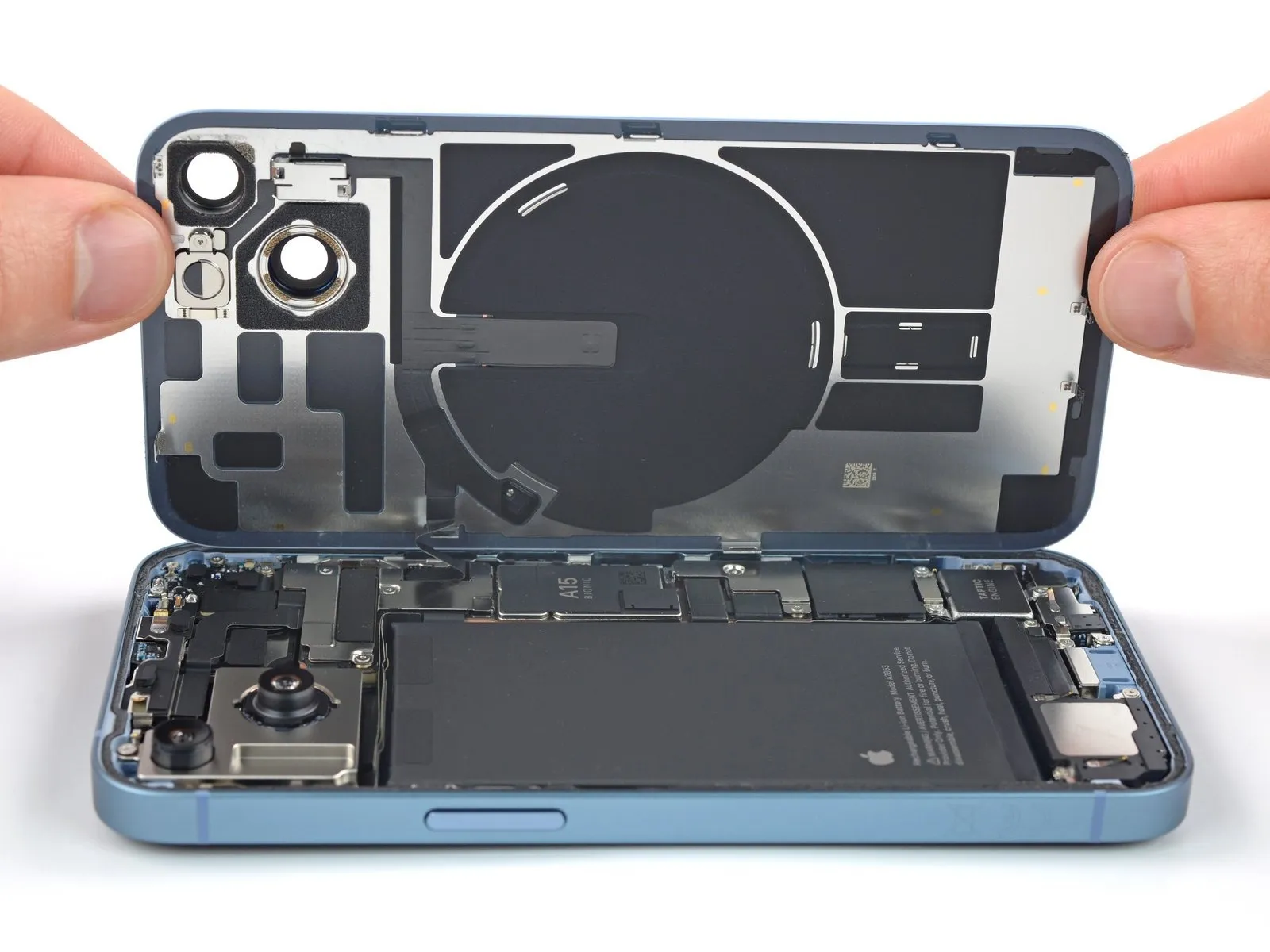
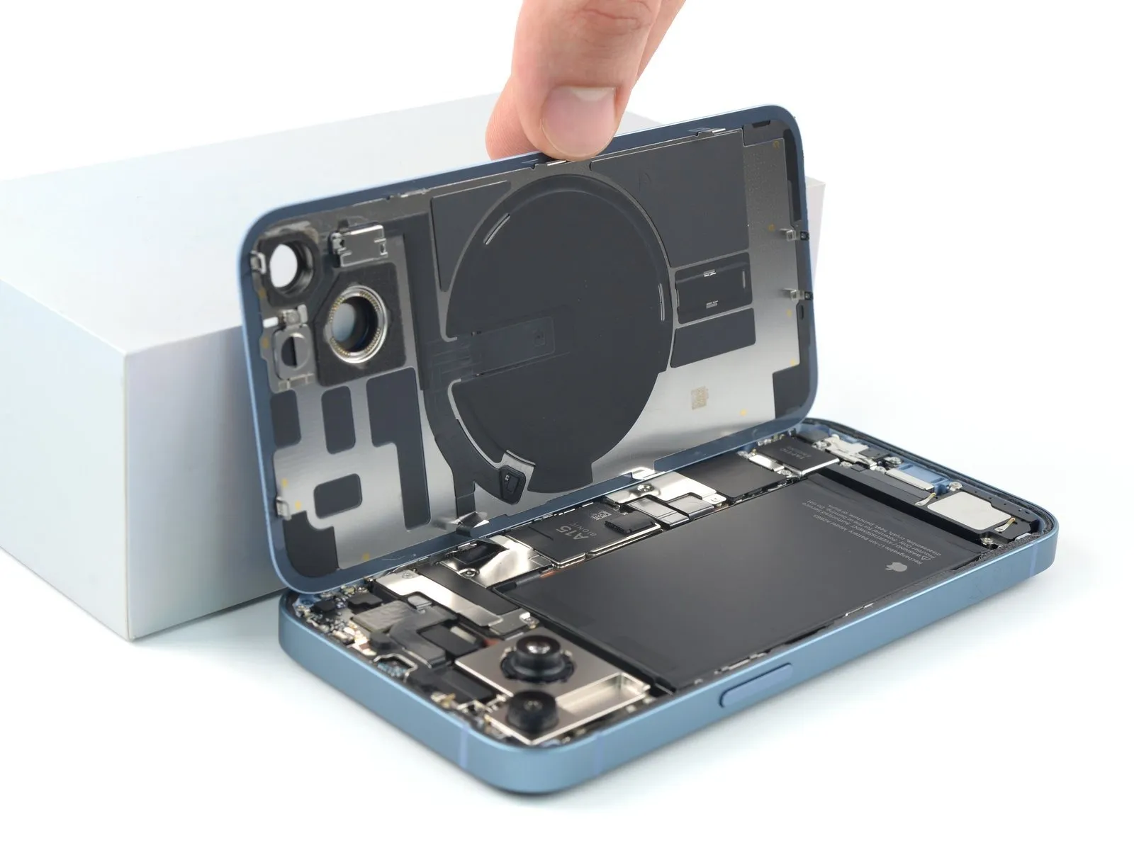
- Detach the suction handle from the rear glass assembly.
- Carefully separate the iPhone's rear glass by pivoting it upwards from the left edge, mimicking the action of opening a book's cover.
- Exercise caution to prevent damage to the brief charging coil flex cable.
- Support the rear glass in an upright position during the repair process; alternatively, the suction handle can serve this purpose if a separate support is unavailable.
Step 15 | Unfasten the battery connector cover screws
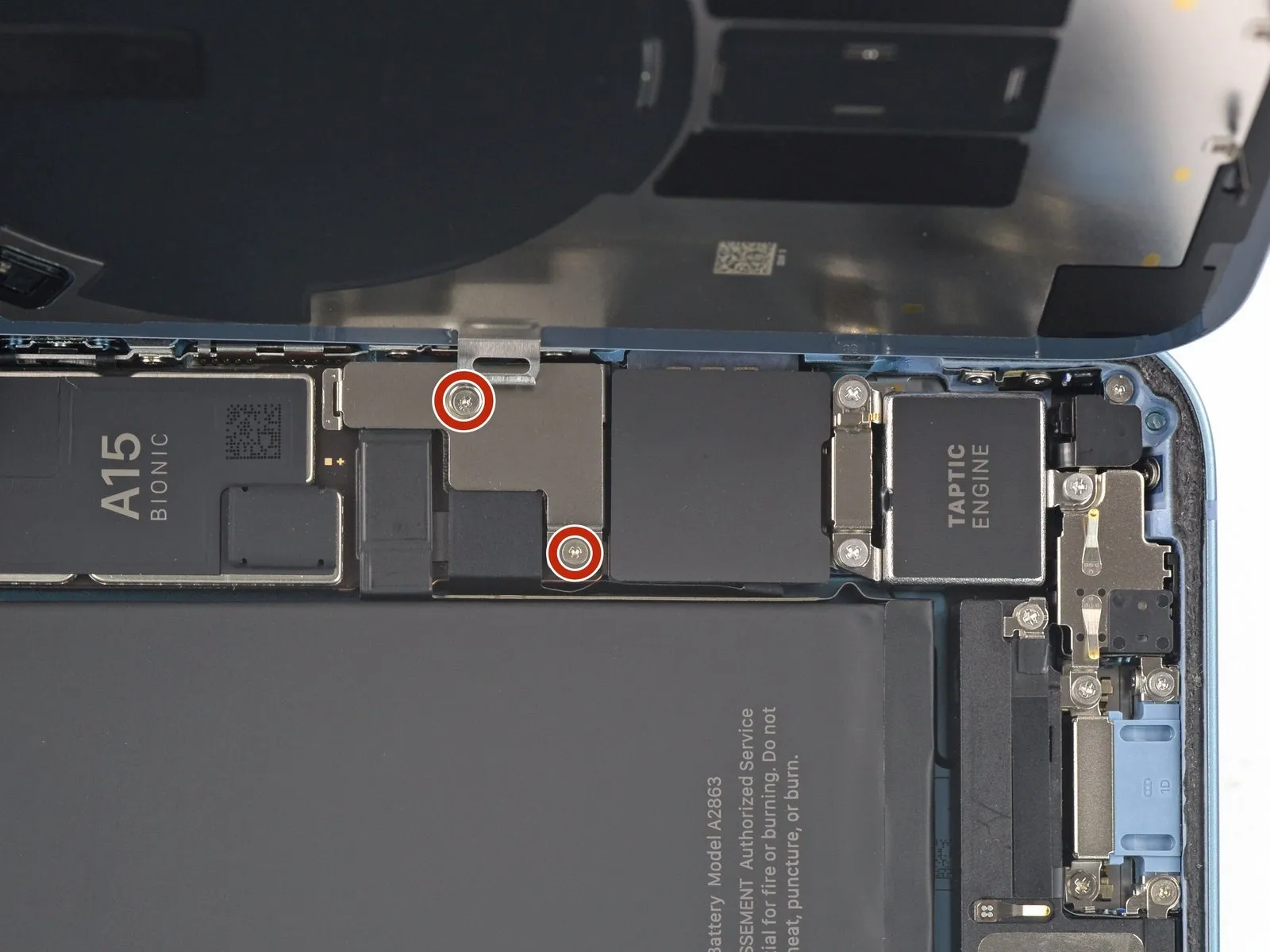
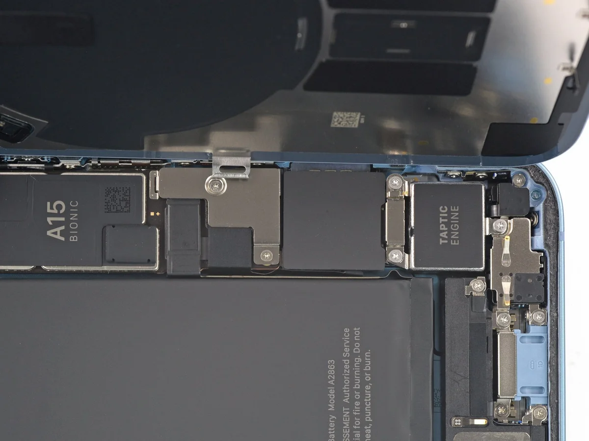
- Employ a Y000 screwdriver for the removal of the two screws, each measuring 1.3 mm in length, which fasten the battery connector cover.Meticulous organization of each screw is essential during this repair process, ensuring correct placement upon reinstallation to prevent potential iPhone damage.To prevent component damage, maintain a record of the location of each screw throughout the repair procedure.
- A functional test of all iPhone features, including powering the device on, is recommended at this stage during reassembly, prior to final display sealing.
- Complete power-down of the iPhone is required before proceeding with subsequent repair steps following the functional test.
Step 16 | Remove the battery connector cover
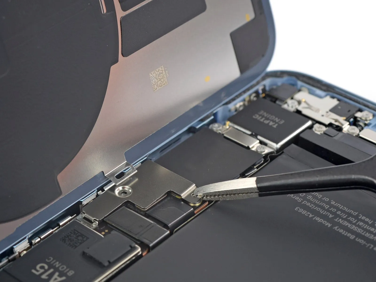
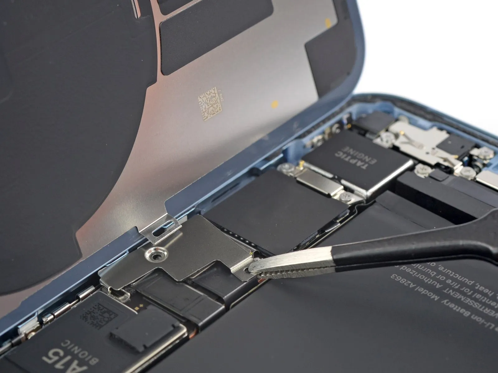
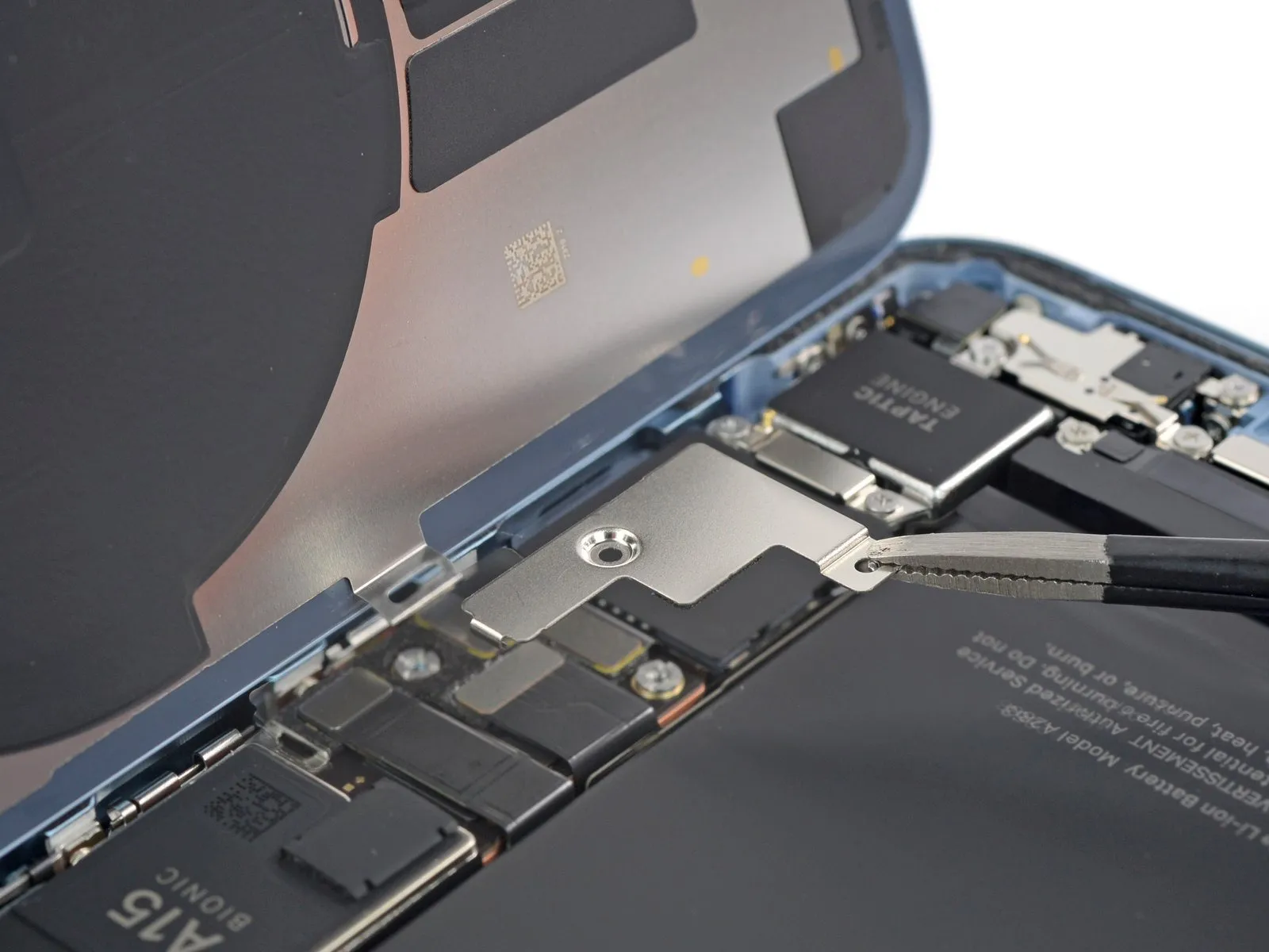
- Using tweezers, secure the battery connector cover and move it vertically, directing the motion towards the 'A15' marking to release the upper retaining clip.
- Detach the battery connector cover from the device.
Step 17 | Disconnect the battery
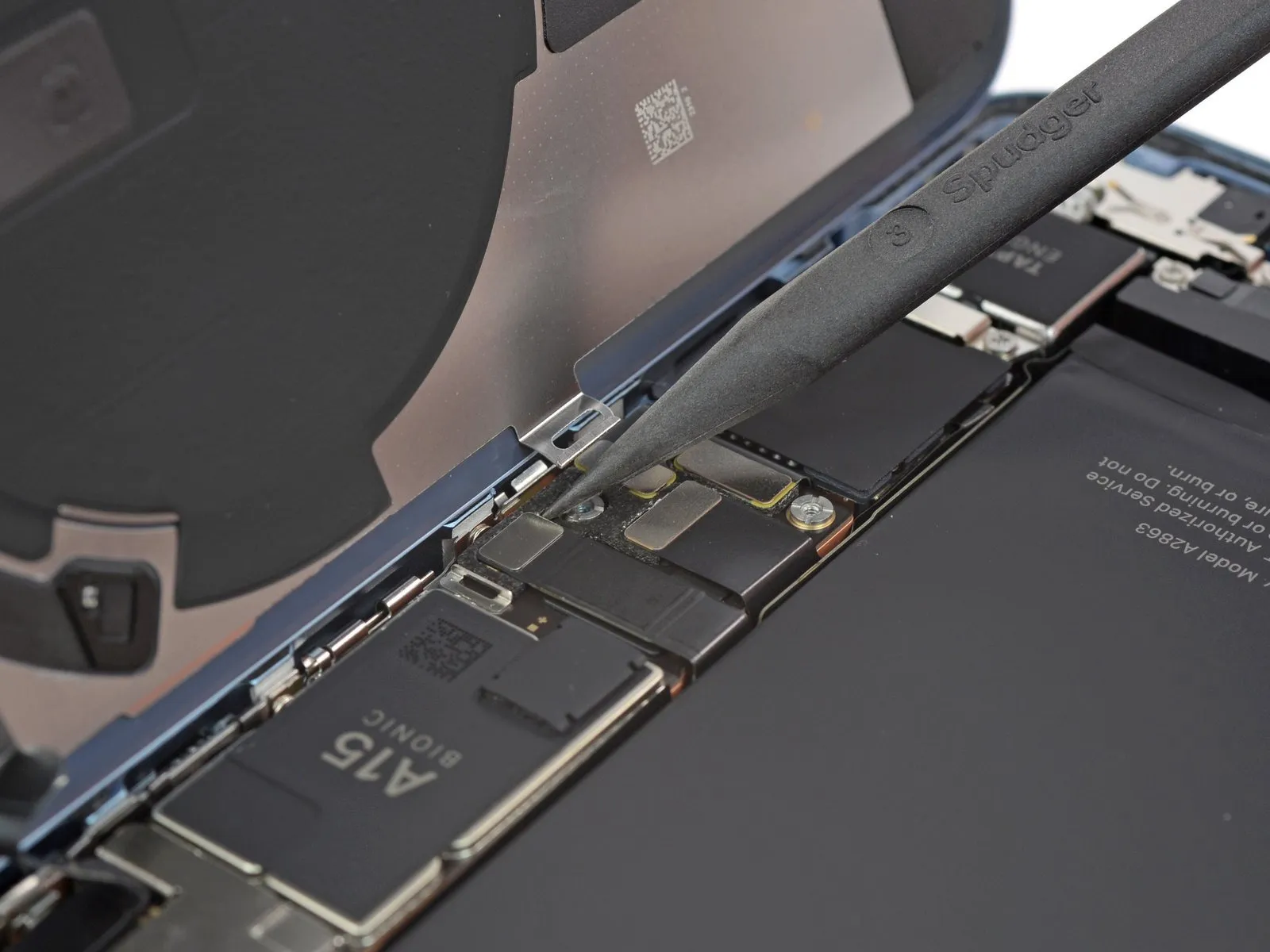
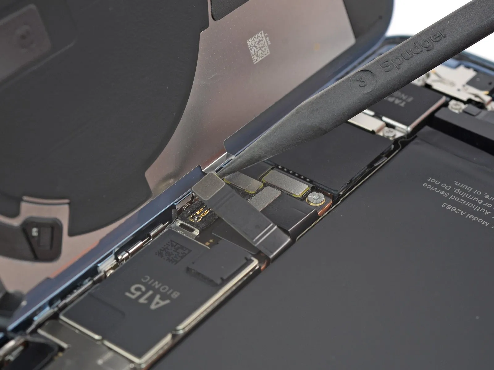
- Employ the tapered end of a spudger to release the battery connector, lifting it vertically from its receptacle.Exercise caution to avoid harming the black silicone sealant found around this and other board interfaces, as it safeguards against water and dust ingress.To inhibit unintended power delivery to the device during the repair process, slightly deflect the connector away from the logic board's socket.
- The battery cable's disconnection requires a precise upward force applied directly to the connector's body.
- Maintaining the integrity of the silicone seals is crucial for preserving the device's environmental protection capabilities.
Step 18 | Unfasten the charging coil connector cover screw
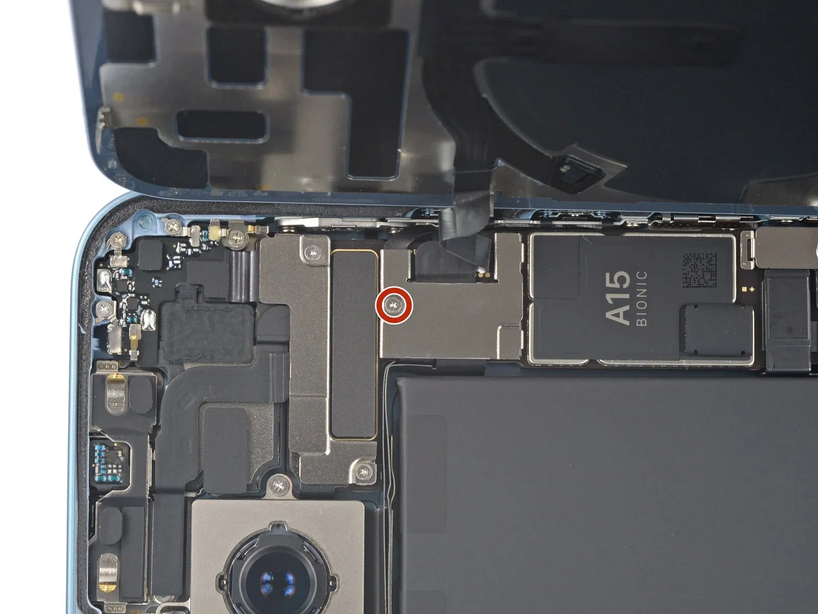
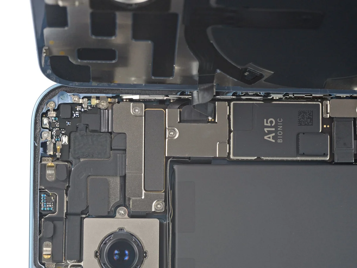
- Employ a Y000 screwdriver for the task of detaching the charging coil connector cover.A Y000 screwdriver is required to loosen the fastener.The charging coil connector cover is held in place by a single screw.The screw, measuring 1.0 mm in length, must be carefully removed.Securely hold the charging coil connector cover while disengaging the 1.0 mm screw with the Y000 screwdriver.
Step 19 | Remove the charging coil connector bracket
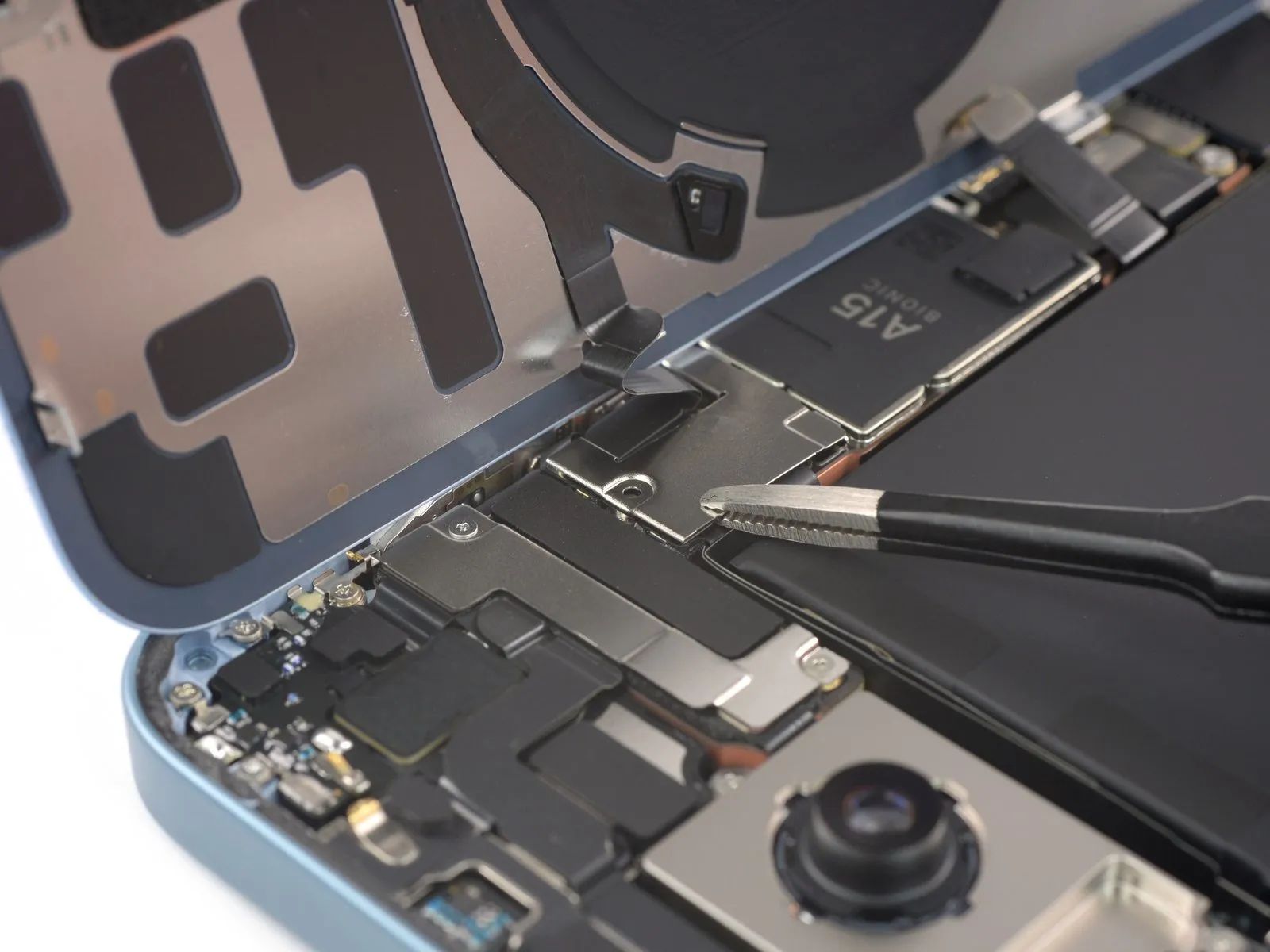
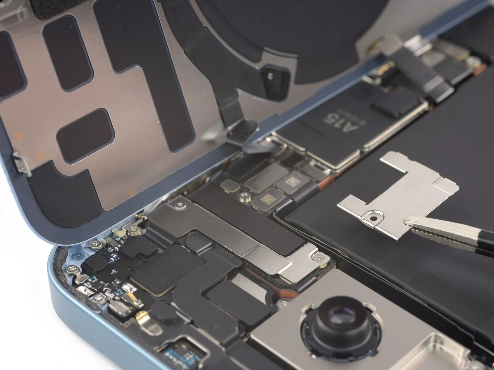
- Employing tweezers, detach the protective cover that secures the charging coil connector.
Step 20 | Disconnect the charging coil
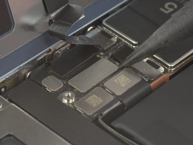
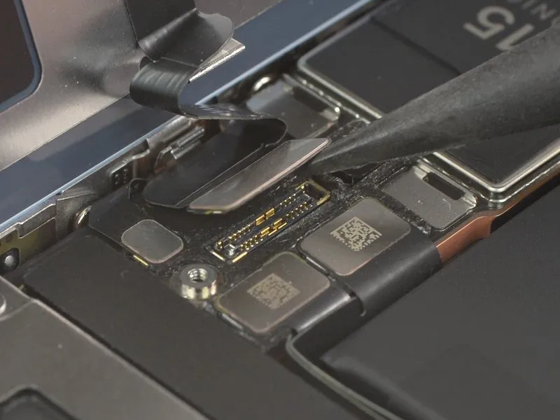
- Employ the tapered tip of a spudger to release the charging coil cable's connector, lifting it vertically away from its receptacle.Carefully separate the charging coil cable connector from its socket utilizing the pointed end of a spudger, ensuring a straight upward motion.To detach the charging coil cable, a spudger's pointed end should be used to lever the connector vertically out of its socket.
Step 21 | Remove the rear glass assembly
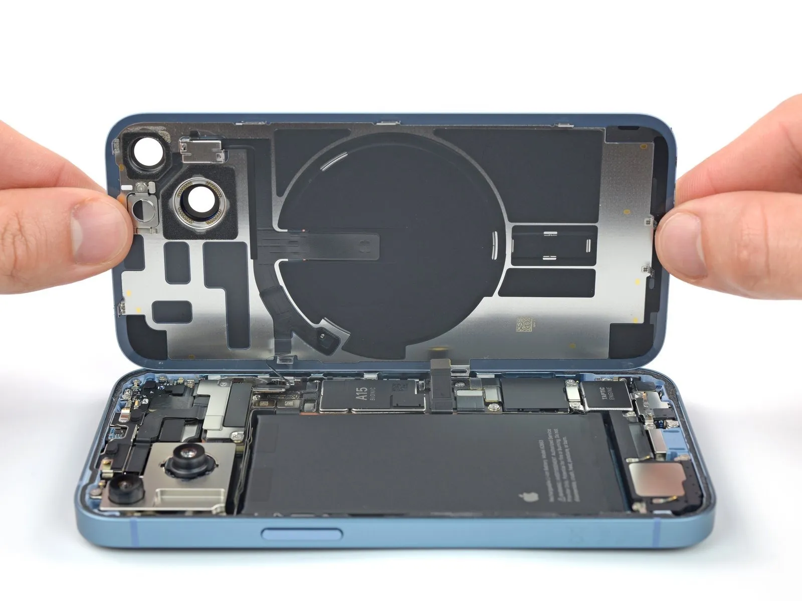
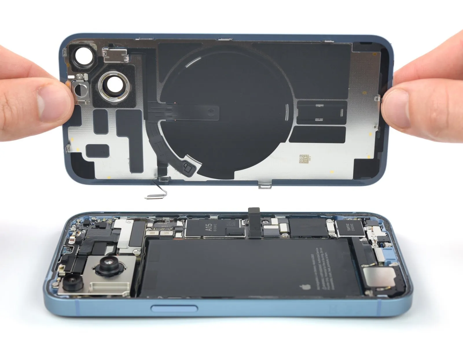
- Detach the rear glass component from the device.
- Following a thorough cleaning of the surfaces with isopropyl alcohol exceeding 90% purity, apply fresh adhesive as required.
- If rear glass adhesive replacement is desired, halt the reassembly process at this stage.
Step 22 | Unfasten the front camera assembly cable bracket screws

Employ a Y000 screwdriver for the disassembly process.The two screws, each measuring 1.3 millimeters in length, require removal.These screws are responsible for fastening the front camera assembly cable bracket.Carefully detach the bracket using the specified screwdriver.Ensure proper tool selection to avoid damage to the delicate components.
Step 23 | Remove the front camera assembly cable bracket


Employ tweezers or your fingertips to detach the securing bracket for the front camera assembly cable.
Step 24 | Disconnect the camera and sensor cable

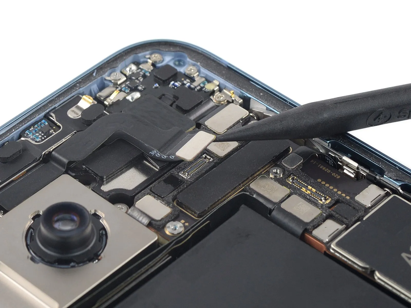

Employ a spudger to release the camera and sensor cable connectors, lifting them vertically away from their receptacles.
Step 25 | Remove the front-facing camera assembly


Employing tweezers or direct manual manipulation, detach the front-facing camera and associated sensor module.The front-facing camera and sensor assembly can be dislodged using tweezers or by carefully grasping with your fingertips.To extract the front-facing camera and its sensor, utilize tweezers or manually remove it.
Step 26 | Disconnect the antenna


- The subsequent procedures detail the process of detaching an antenna present in certain device configurations; if your device lacks this component, proceed past these instructions.
- Employ a specialized tool, a "spudger", to release the antenna cable's connection.Apply the spudger to the connector, exerting upward force to separate it from its receptacle.This disconnection is achieved by applying direct, vertical pressure with the spudger.
Step 27 | Remove the antenna


- A minimal amount of adhesive secures the antenna to the surface of the earpiece speaker.
- Utilize the pointed end of a spudger tool.Position the spudger's tip beneath the upper-left corner of the antenna.Apply gentle upward force to release the adhesive bond securing the antenna.
- Carefully detach the antenna from the earpiece.
- Complete the removal process by separating the antenna from its affixed position.
Step 28 | Disconnect the earpiece speaker


Employ a spudger to release the earpiece cable's connection, achieving this by applying upward force to the connector and separating it from its receptacle.The earpiece cable connector should be detached from its socket using a spudger, ensuring a straight upward motion during the separation process.To disengage the earpiece cable, utilize a spudger, carefully levering the connector vertically out of its corresponding socket.
Step 29 | Unfasten the earpiece speaker screws

- Employ a Phillips screwdriver for the disassembly of the earpiece speaker's mounting hardware.The required tool for this step is a Phillips head screwdriver.Five screws, each measuring 1.4 millimeters in length, hold the earpiece speaker in place.These fasteners, with a length of 1.4 mm, must be removed using the appropriate screwdriver.To detach the earpiece speaker, the five screws of 1.4 mm length need to be unscrewed with a Phillips screwdriver.
Step 30

- Employ a Phillips screwdriver for the task of detaching the earpiece speaker.The screw, measuring 1.1 millimeters in length, requires a Phillips screwdriver for removal.To release the earpiece speaker from the device's frame, a Phillips screwdriver is necessary.A 1.1 mm Phillips screw fastens the earpiece speaker and must be unscrewed.The earpiece speaker is affixed to the frame via a screw that is 1.1 mm in length, and a Phillips screwdriver is needed to remove it.
Step 31 | Remove the earpiece speaker


- Employ tweezers or manual dexterity to detach the earpiece speaker component.
A rubber gasket, situated on the upper left perimeter of the earpiece speaker, necessitates precise alignment with its corresponding indentation within the frame during reassembly.