iPhone 14 Screen Replacement
When an iPhone 14 exhibits a cracked display, unresponsive touch input, or a blank image upon activation, this detailed procedure will enable you to return the device to operational status by installing a replacement display assembly.The display unit, also referred to as the screen, is the component being addressed in this repair process.This instructional document was developed utilizing the A2882 (international) iPhone 14 variant; while minor visual differences might exist for other models, the core repair steps remain consistent.
Be aware that features like True Tone and automatic brightness are temporarily deactivated following a display replacement, even when utilizing an authentic Apple screen, on iOS versions up to 17.6.
Furthermore, Face ID functionality will be unavailable unless the iPhone's operating system is iOS 15.2 or a later release.With the most recent iOS software, True Tone can potentially be reactivated through Apple's Repair Assistant, which may occur automatically during the setup process.To ensure a proper seal and device stability during reassembly, replacement adhesive is essential for securing the display unit.Following the repair, the iPhone will operate as expected; however, the device's Ingress Protection (IP) rating will likely be compromised.A damaged screen often presents with visible cracks or areas where touch interaction is absent.
- Carefully observe the orientation of all cables and connectors during disassembly to prevent damage.Use appropriate tools, such as a P2 Pentalobe screwdriver, a suction cup, and opening picks, to avoid scratching or damaging the iPhone's casing.Always ground yourself before handling internal components to prevent electrostatic discharge (ESD) damage.
- Prior to commencing the repair, back up your iPhone data to prevent potential data loss.
Step 1 | Remove the pentalobe screws
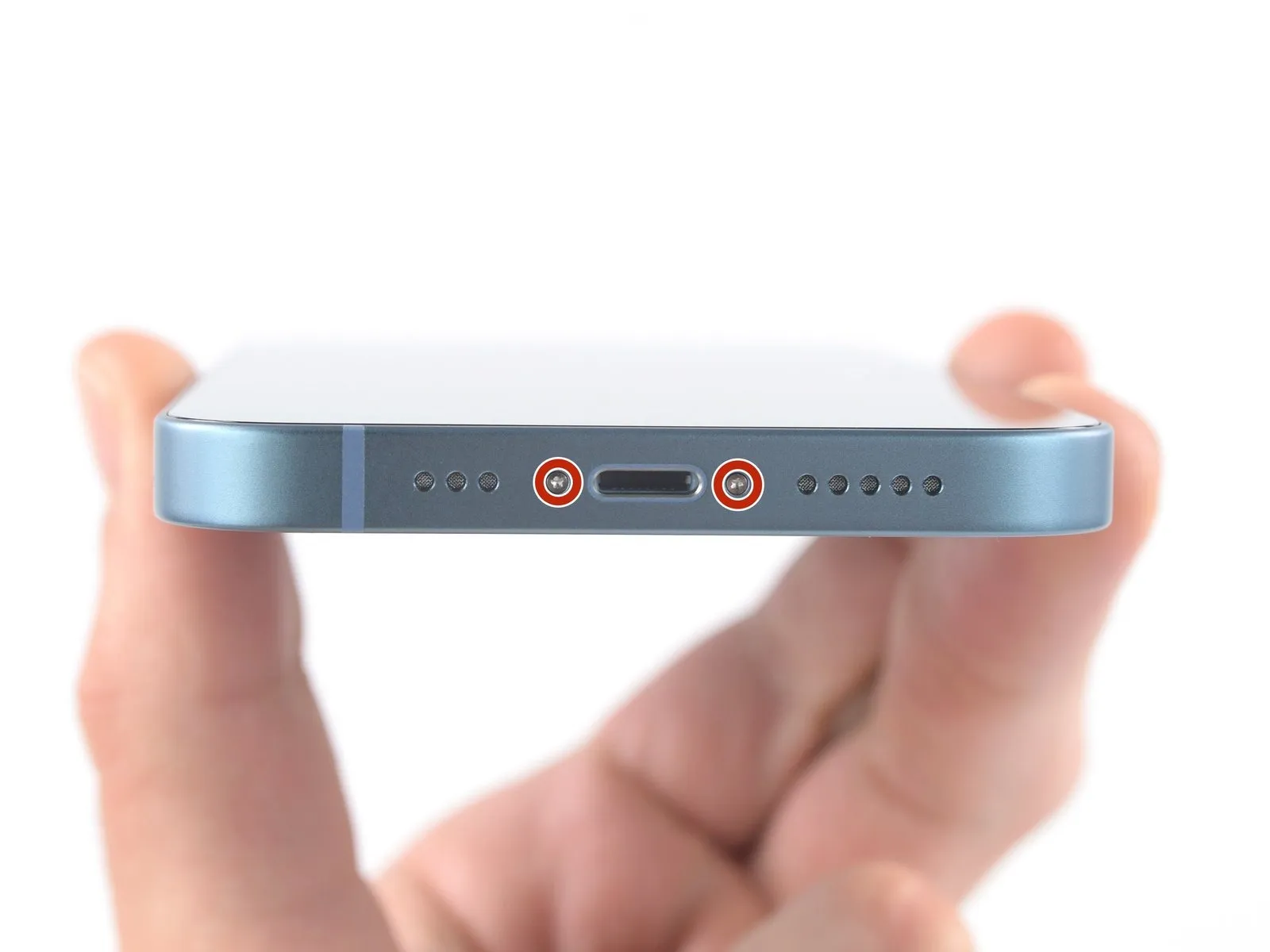
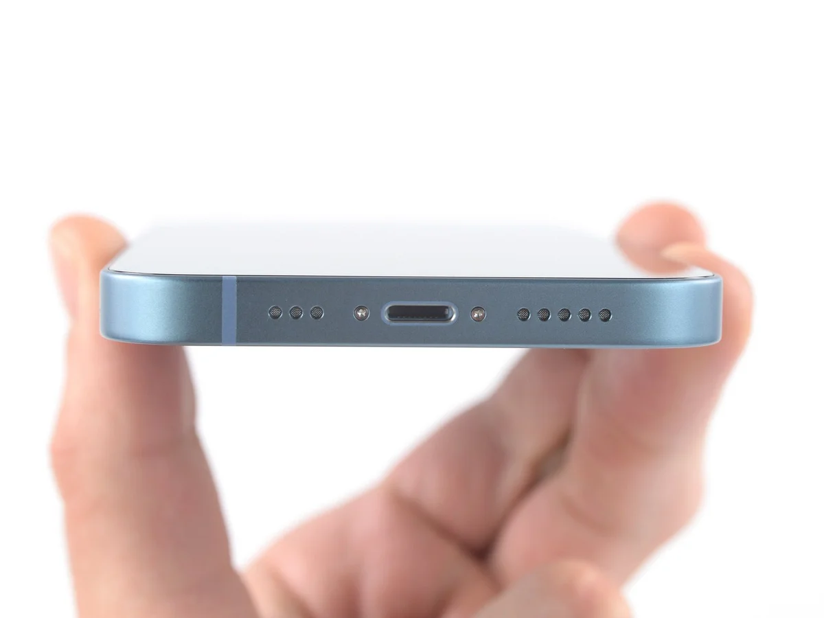
- Prior to commencing the iPhone's disassembly process, ensure the device is completely powered down.
- The two screws, each measuring 6.8 millimeters in length and utilizing a Pentalobe P2 head, must be detached.These screws are located on the lower perimeter of the iPhone's casing.Successful removal of these fasteners is necessary for proceeding with the repair.
Step 2 | Mark your opening picks


- Excessive insertion of a spudger can potentially harm the device; therefore, it's crucial to implement a marking procedure to avoid such incidents.
Using a precise measuring tool, determine a distance of3 millimetersfrom the distal end of the opening pick and clearly indicate this point with a permanent marking instrument. - For enhanced precision, consider marking the remaining corners of the pick with varying measurement distances.
- As an alternative method, affix a coin to the opening pick, positioning it3 millimetersfrom the tip to serve as a visual depth guide.
Step 3 | Tape over any cracks


- To minimize additional damage and potential injury while repairing a fractured iPhone display, secure the glass with adhesive tape.
Apply successive layers of transparent packing tape across the iPhone's screen surface, ensuring complete coverage of the entire front panel. - Protect your vision by utilizing safety eyewear to guard against any dislodged glass fragments that might occur during the repair process.
- Should the suction cup fail to maintain adhesion during subsequent procedures, construct a handle from a robust tape (like duct tape) and employ it to elevate the screen.
- As a last resort, secure the suction cup to the screen's surface using superglue to facilitate lifting.
Step 4 | Heat the bottom edge

- Apply warmth to the iPhone's lower perimeter utilizing a hair dryer or heat gun, ensuring the screen's surface temperature reaches a point of slight discomfort upon contact.
Avoid prolonged, localized heat application with the heat gun to prevent damage.
Step 5 | Insert an opening pick
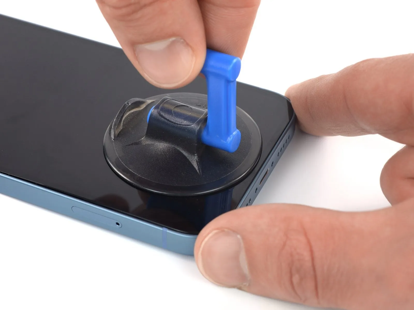
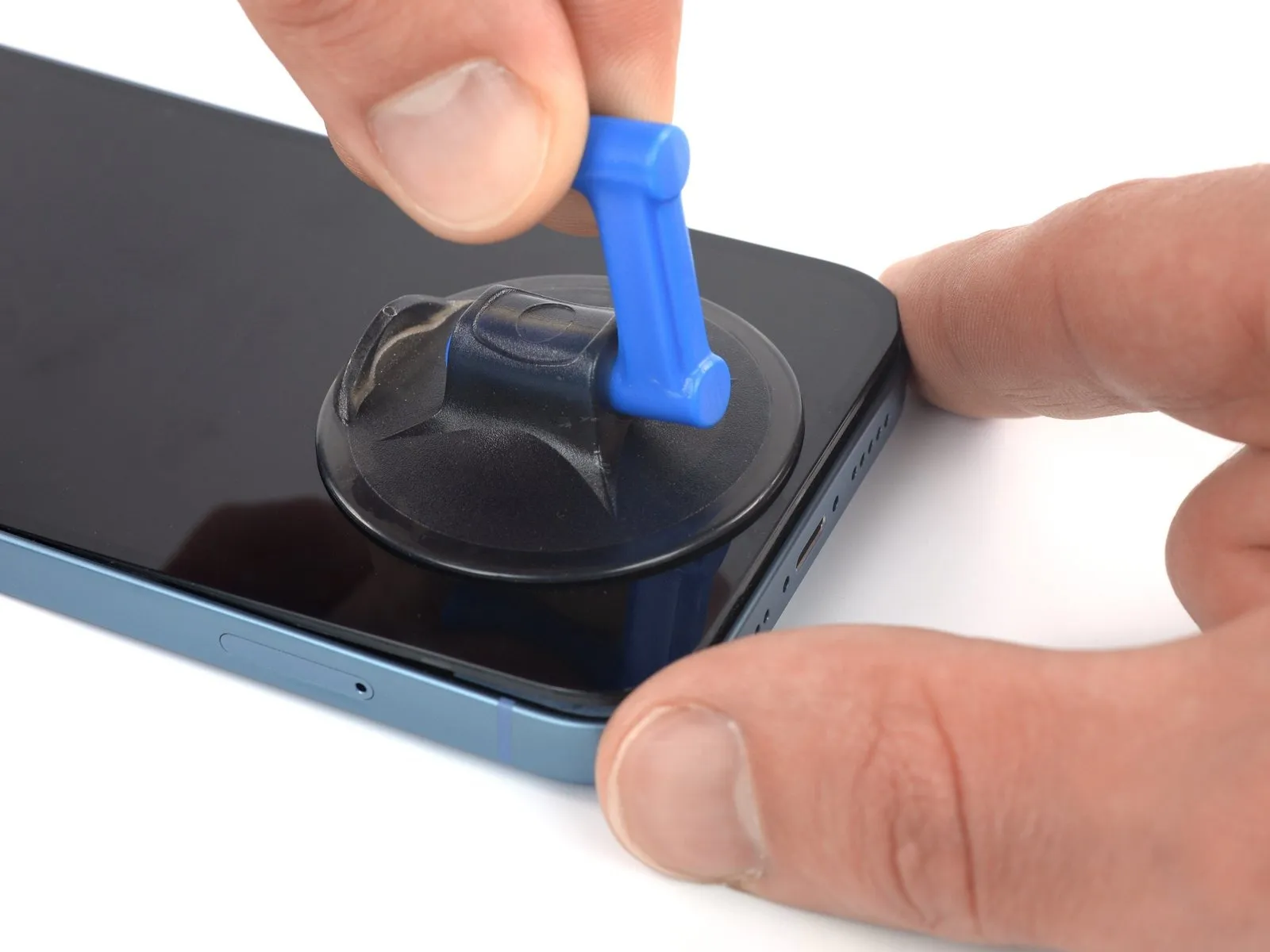
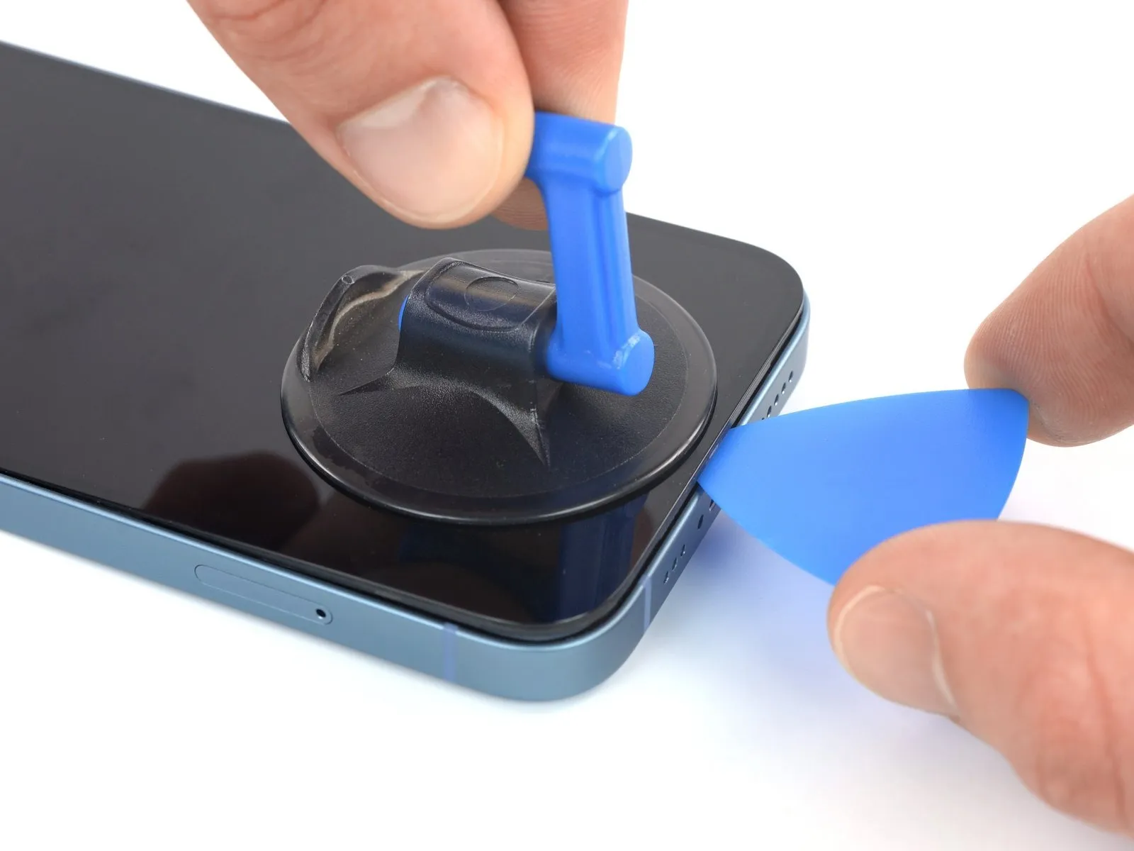
- Securely attach a suction handle to the lower perimeter of the device's main body, ensuring it remains clear of the outermost glass boundary.
- Maintain steady, consistent upward force on the suction cup to generate a small separation between the display assembly and the surrounding chassis.
- Carefully slide an opening tool into the newly formed space located beneath the screen's decorative plastic trim.
- Due to the robust nature of the screen's adhesive, considerable force may be necessary to initially separate the components; if resistance is encountered, apply additional heat and gently oscillate the screen to reduce adhesive strength until a sufficient gap is achieved for tool insertion.
Step 6 | Separate the bottom edge adhesive


- Ensure the initial insertion of your separating tool does not exceed a depth of 3 millimeters from the lower border.Employ a reciprocating motion with the tool along the lower edge to sever the adhesive bond.Maintain the tool's position within the lower-right corner to inhibit adhesive re-adhesion.
- The adhesive's separation is achieved through a back-and-forth movement of the tool along the specified edge.
- To avoid the adhesive re-establishing a seal, keep the separating tool in place at the lower right corner.
Step 7 | Heat the right edge


Apply warmth to the right-hand side of the iPhone's casing, specifically the perimeter containing the power button, until the display surface reaches a temperature just beyond comfortable touch.The targeted area, the right edge featuring the power button, should be warmed to a point where tactile sensation indicates a slight discomfort.Ensure the temperature applied to the right edge, which houses the power button, is sufficient to create a perceptible warmth on the screen's surface.
Step 8 | Separate the right adhesive
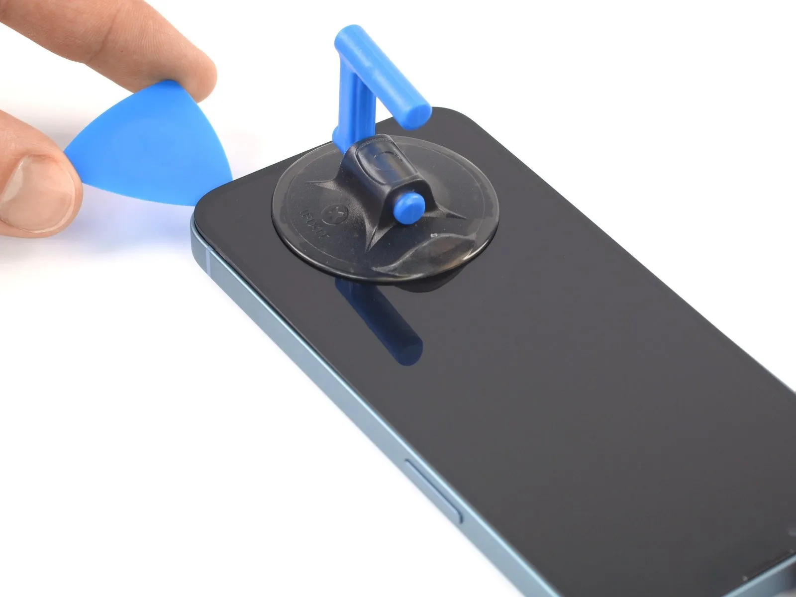
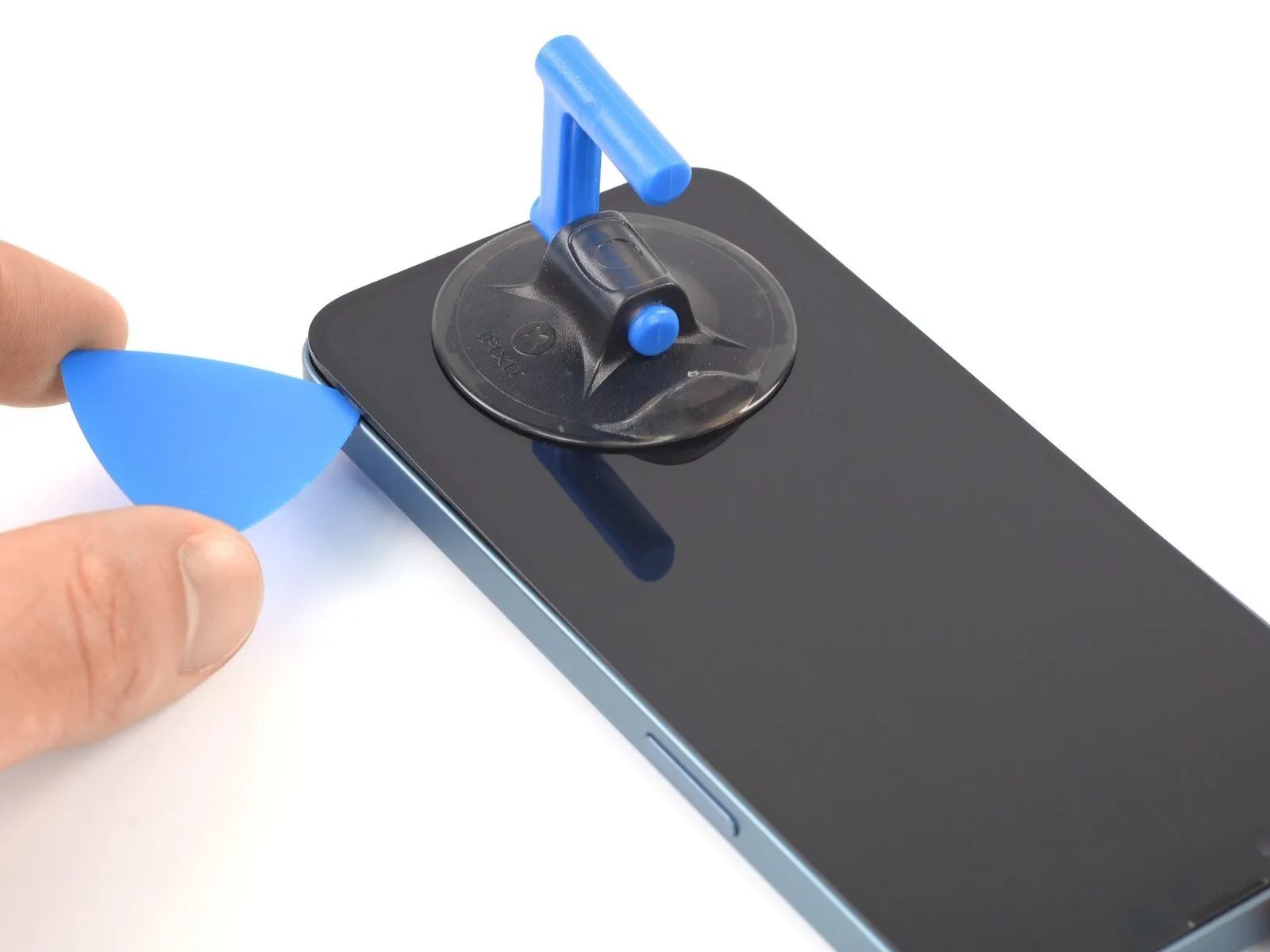
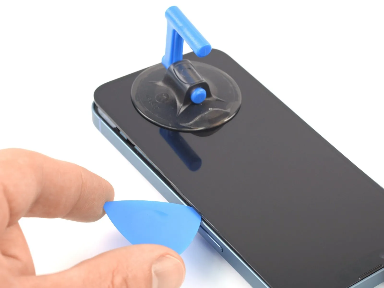
- Employ an opening pick and maneuver it along the lower-right perimeter of the iPhone to release the securing adhesive.
- Proceed with sliding the pick upward along the right-hand side of the iPhone's casing.Advance the pick's movement until it arrives at the upper-right corner of the device.Limit the pick's insertion depth to a maximum of 3 millimeters to prevent potential harm to the internal components.
- Maintain the pick's position within the top-right corner before proceeding with subsequent steps.The adhesive bond is designed to be strong, requiring careful and deliberate separation.Exerting excessive force or inserting the pick too deeply can result in irreparable damage to delicate internal parts.
- Proper alignment and controlled movement of the opening pick are essential for a successful repair.
Step 9 | Heat the top edge

To facilitate separation, apply heat to the iPhone's upper perimeter until the display surface reaches a temperature that is marginally uncomfortable to the touch.
Step 10 | Separate the top adhesive


- To prevent component damage, limit pick insertion depth to a maximum of 3 millimeters.The top edge of the device requires careful manipulation during separation.
- Employing a pick, maneuver along the upper-right corner and subsequently the top edge to disengage the two clips and the adhesive that holds the component in place.
Step 11 | Heat the left edge


To facilitate separation, apply heat to the left side of the iPhone's enclosure, ensuring the screen surface reaches a temperature just beyond comfortable touch.
Step 12 | Separate the left adhesive


- Fragile wiring is situated along the left-hand side of the iPhone's enclosure.Insertion of any tool beyond a depth of 2 millimeters at this location carries a risk of cable damage.Perform a rotational motion with your opening tool around the upper-left corner of the display.
- Advance your pick along the left edge, toward the bottom corner, to release the securing adhesive.
- Should difficulties arise during adhesive separation, apply localized heat to the left-hand side.
- Reheating the left edge can soften the adhesive, easing the separation process.Localized heat application may be necessary to reduce adhesive bond strength.Care must be taken to avoid excessive force or tool penetration to prevent internal component damage.
Step 13 | Open the iPhone
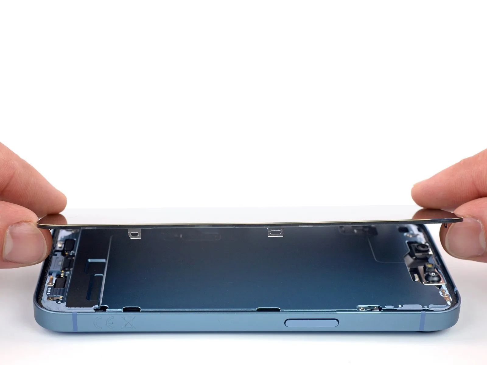
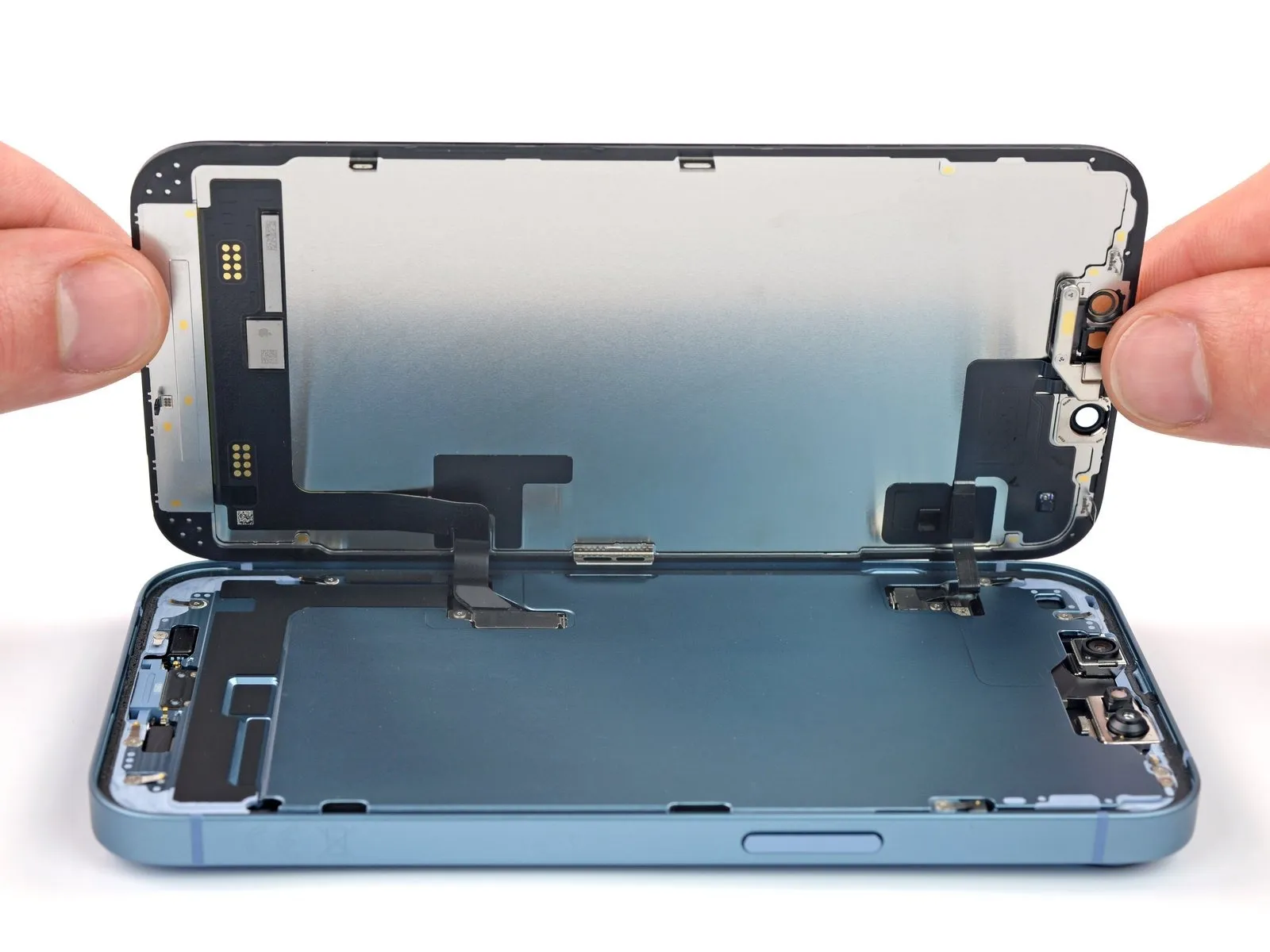
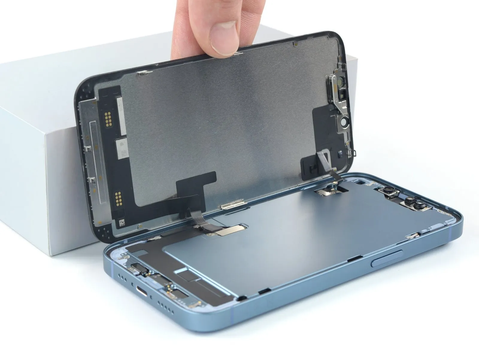
- Detach the suction handle from the display assembly.
- Orient your iPhone, ensuring the right-hand side is directed towards you.
- Separate the iPhone's display by pivoting it upwards from the right side, mimicking the action of opening a book's cover.
- Support the display at an angle to maintain it in a stable position during the repair process.
- Alternatively, the suction handle can be utilized to brace the display if a separate support is unavailable.
When reattaching the display, position it correctly, match the alignment of the top edge clips, and gently apply pressure to secure the top edge before fully engaging the remaining screen perimeter.
Step 14 | Unfasten the display connector bracket screw
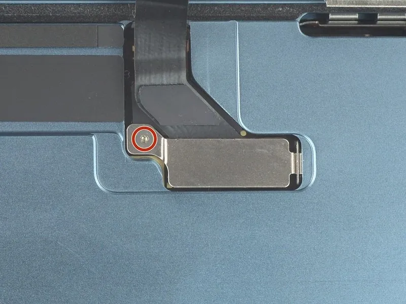
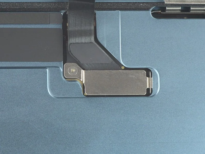
- Employ a Y000 screwdriver to detach the 0.9 mm screw that holds the display connector bracket in position.Meticulously document the location of each screw during disassembly to ensure proper reinstallation and prevent potential damage to the iPhone's internal components.Prior to permanently reattaching the screen, it is advisable to briefly activate the iPhone and verify all features are operating correctly.Completely de-energize the iPhone by powering it off before proceeding with the subsequent steps of the reassembly process.The securement of the display connector bracket is achieved with a single screw measuring 0.9 mm in length.
Maintaining accurate screw placement is critical to avoid causing harm to the iPhone's delicate internal structure.
A functional test of the iPhone's features should be performed at this stage, before the display is finally affixed.
Step 15 | Remove the display connector bracket
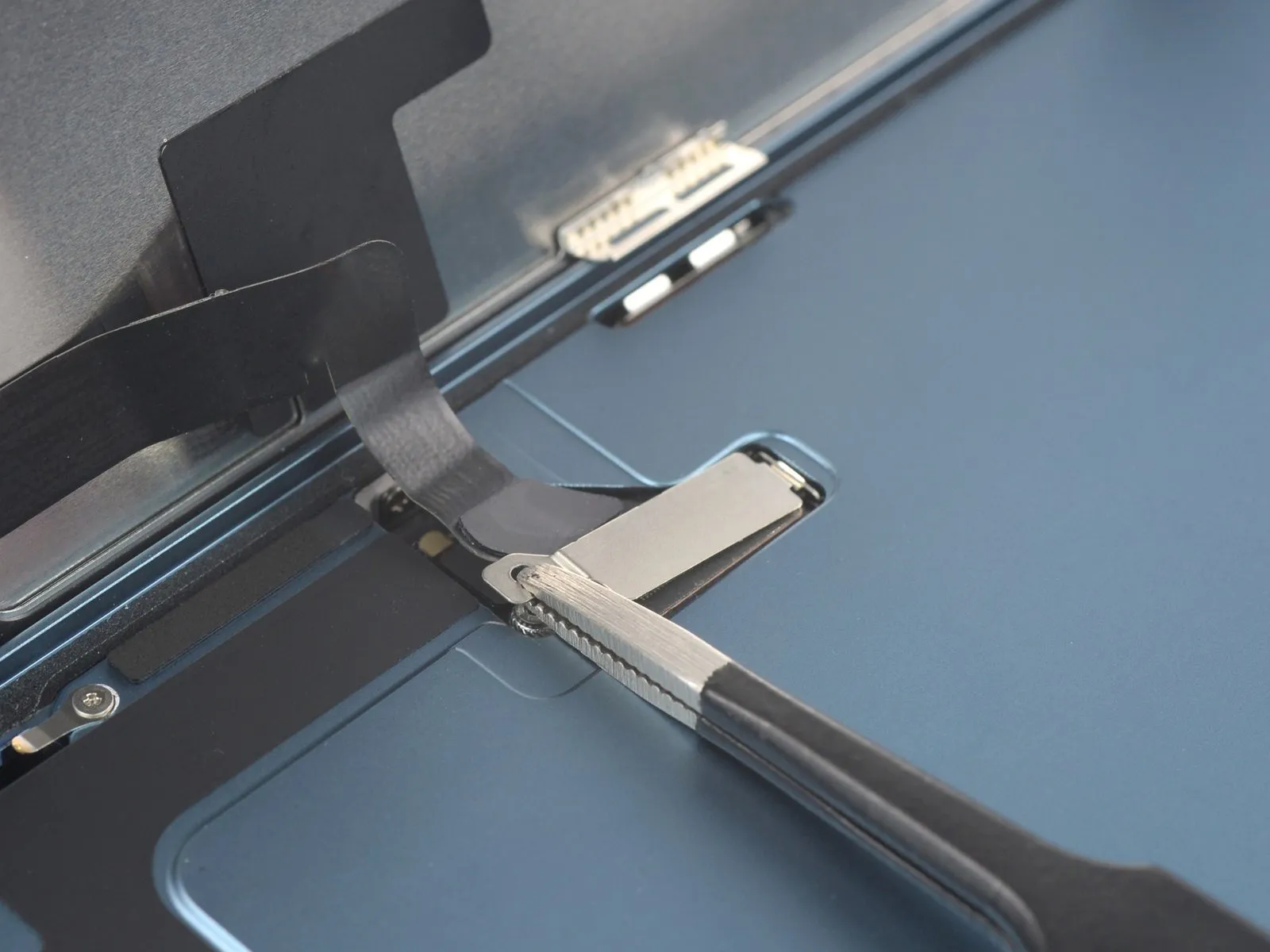
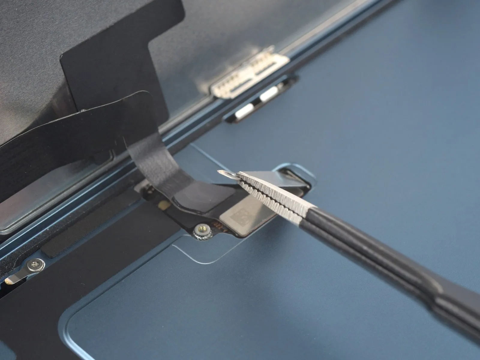
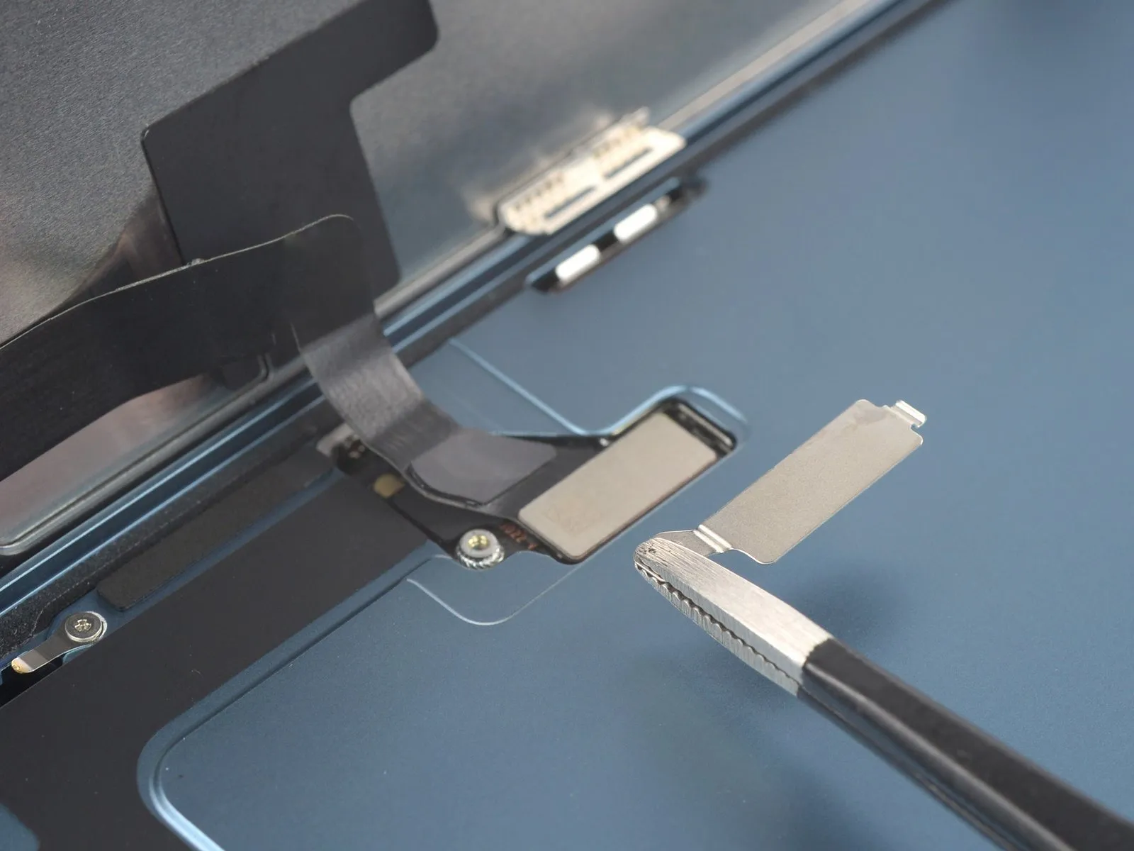
- Employ tweezers to securely hold the connector bracket at its screw-hole end.
- Elevate the bracket a small distance to disengage the retaining latch located on the opposing side.
- Detach the display connector bracket completely from the assembly.
Verify proper engagement of the latching mechanism when reattaching the bracket.
Step 16 | Disconnect the display connector
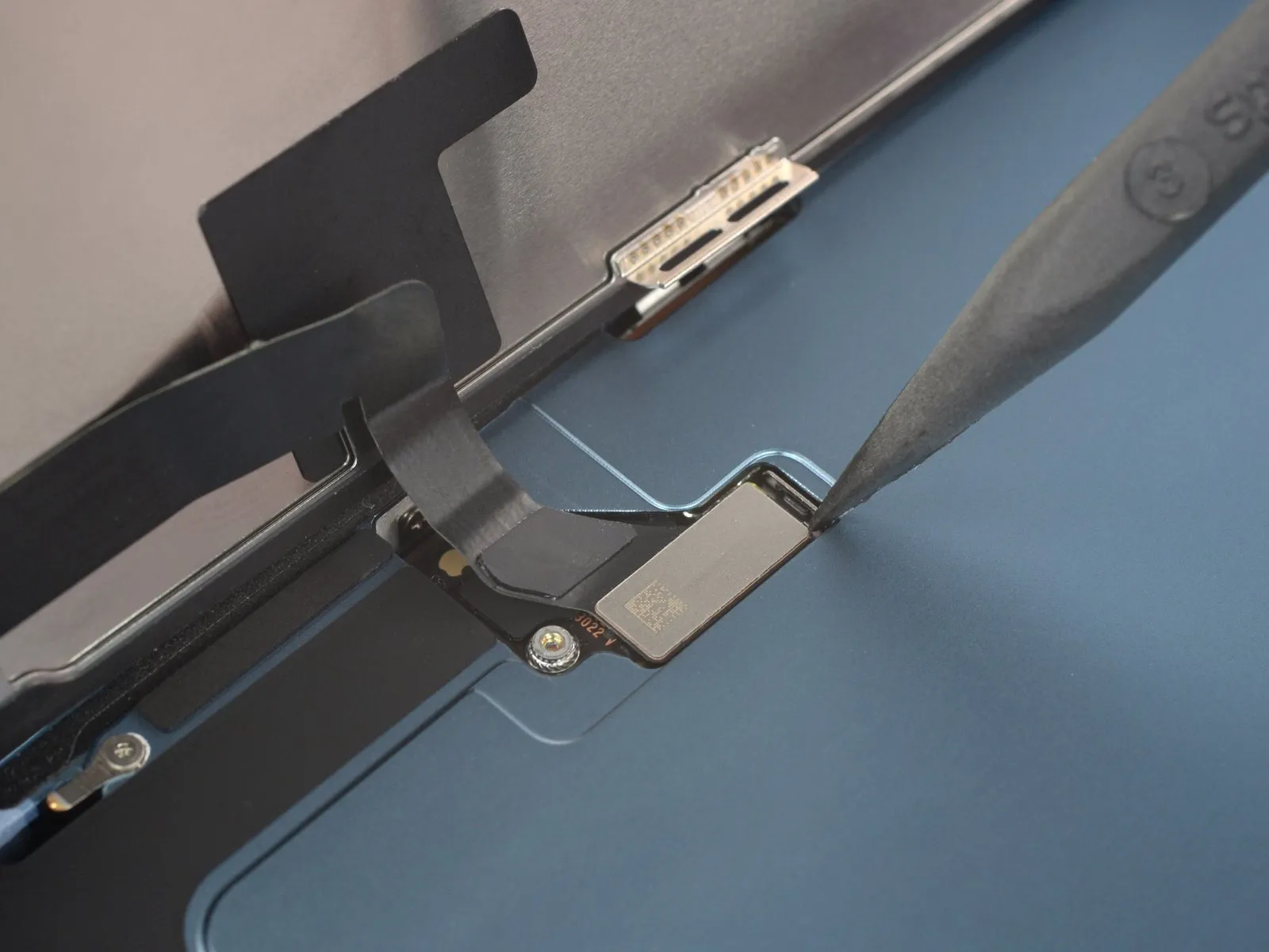
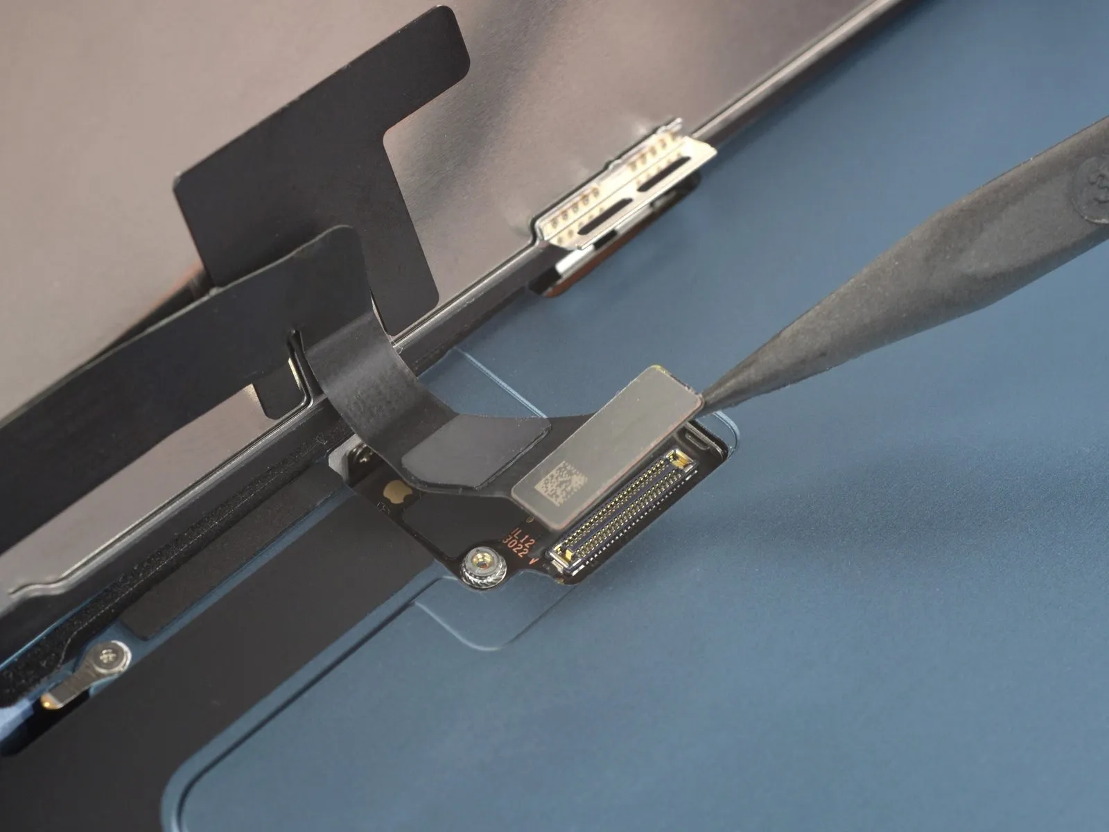
- Employ the tapered end of a spudger to release the display cable's connector; apply upward force directly above the socket to detach it.
For reattachment, align the connector meticulously, then apply downward pressure sequentially to each side until an audible click confirms secure engagement; avoid applying pressure to the central portion, as misalignment risks pin deformation and irreversible component damage.
Step 17 | Unfasten the front sensor connector bracket
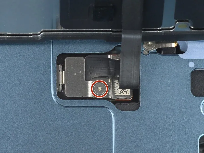
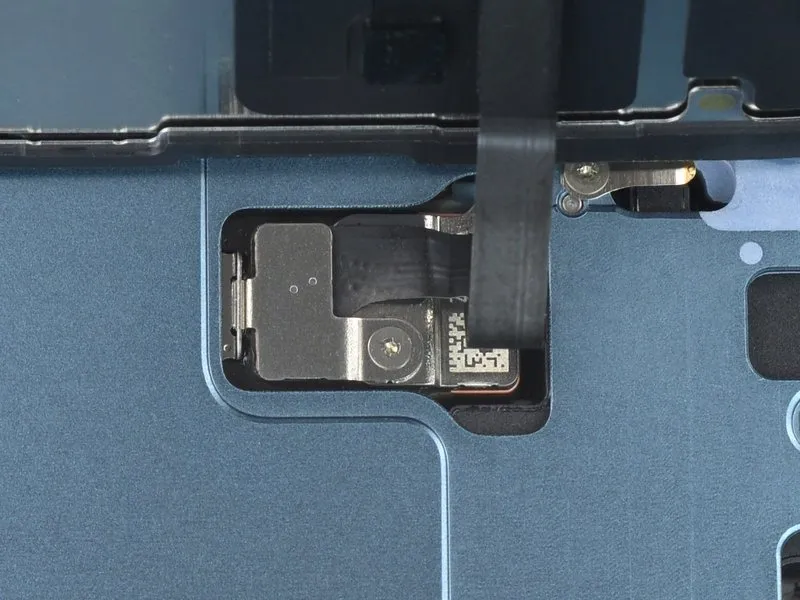
Step 18 | Remove the front sensor connector bracket
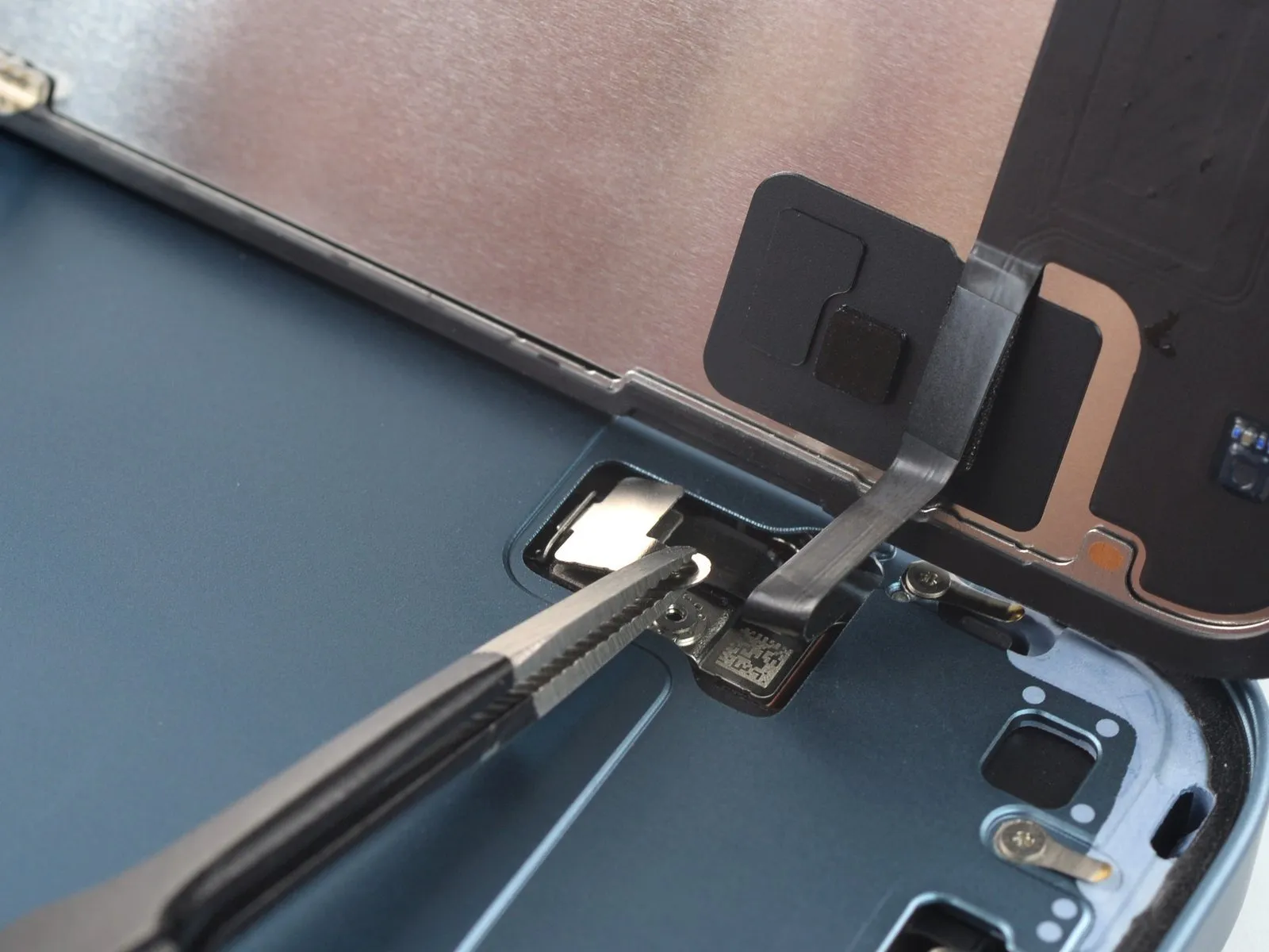
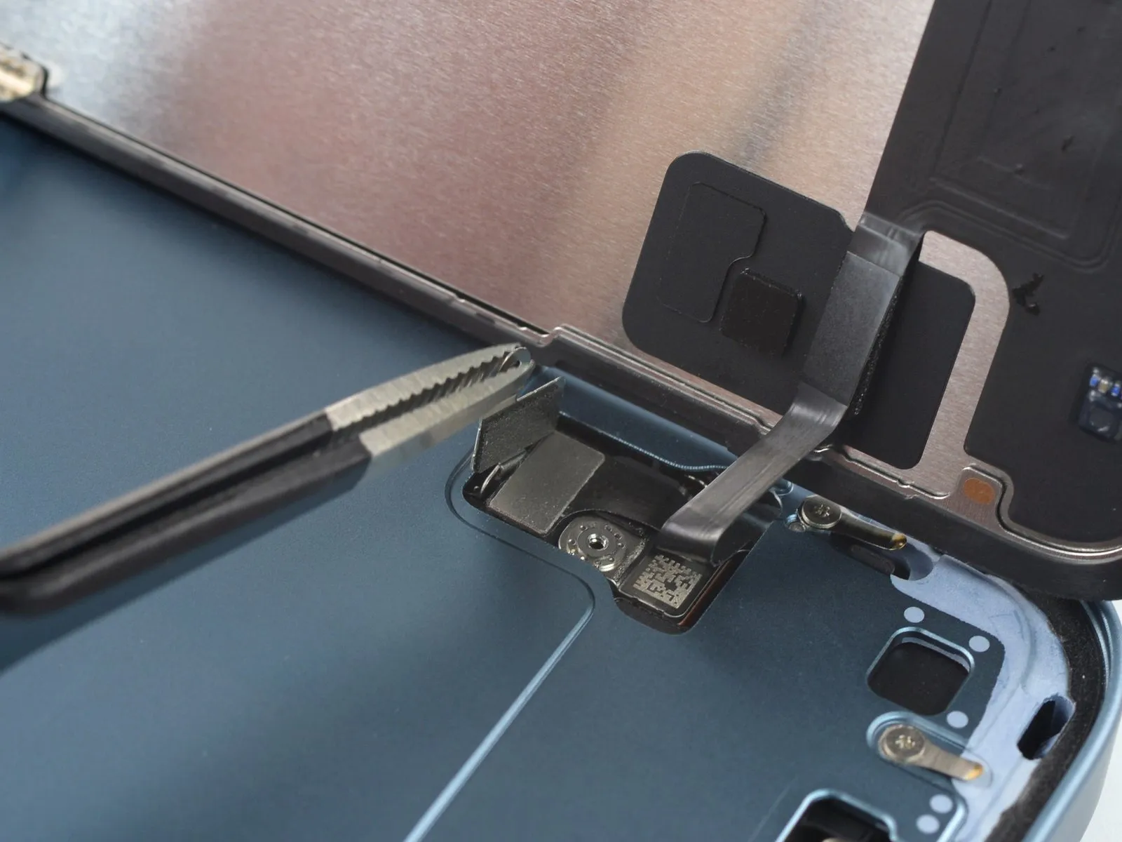
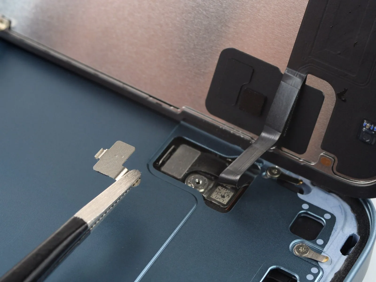
- Utilize tweezers to securely hold the connector bracket at its screw-hole extremity.
- Elevate the bracket a small distance to disengage the retaining latch located on the opposing side.
- Detach the front sensor connector bracket entirely from the device.
- Confirm the bracket's secure latching during the reassembly process to ensure proper function.
Step 19 | Disconnect the front sensor cable
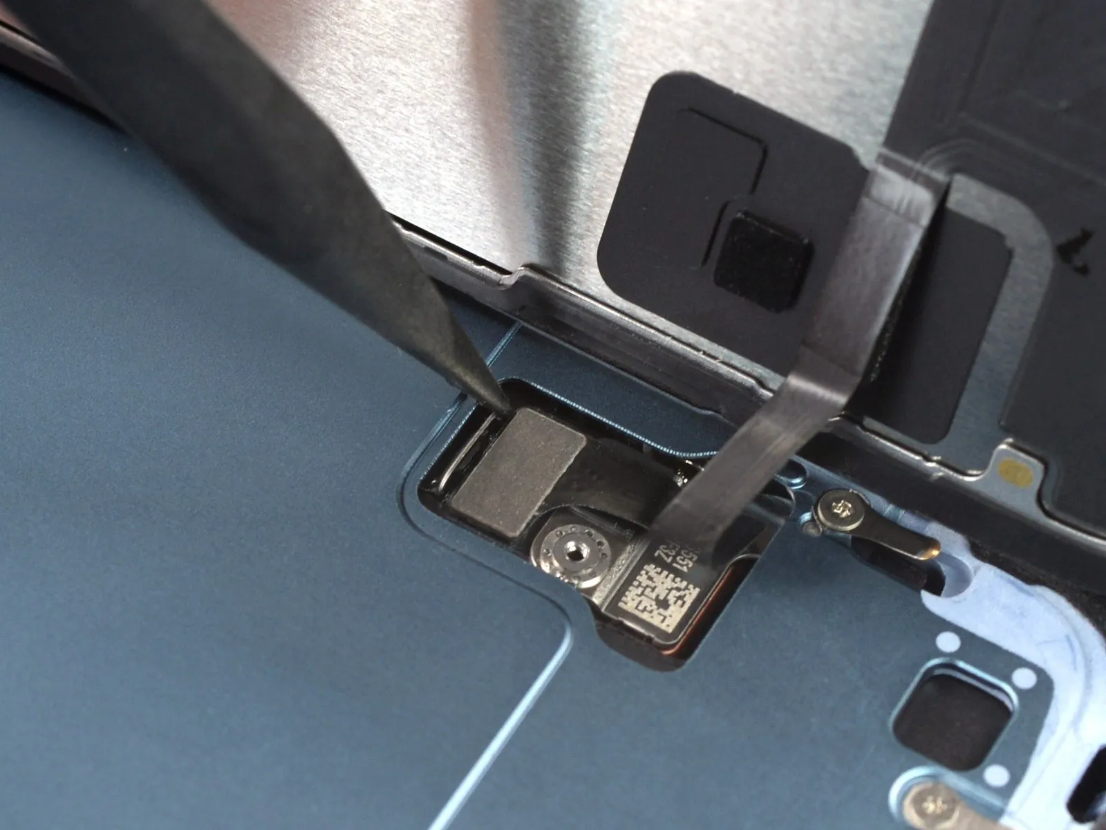
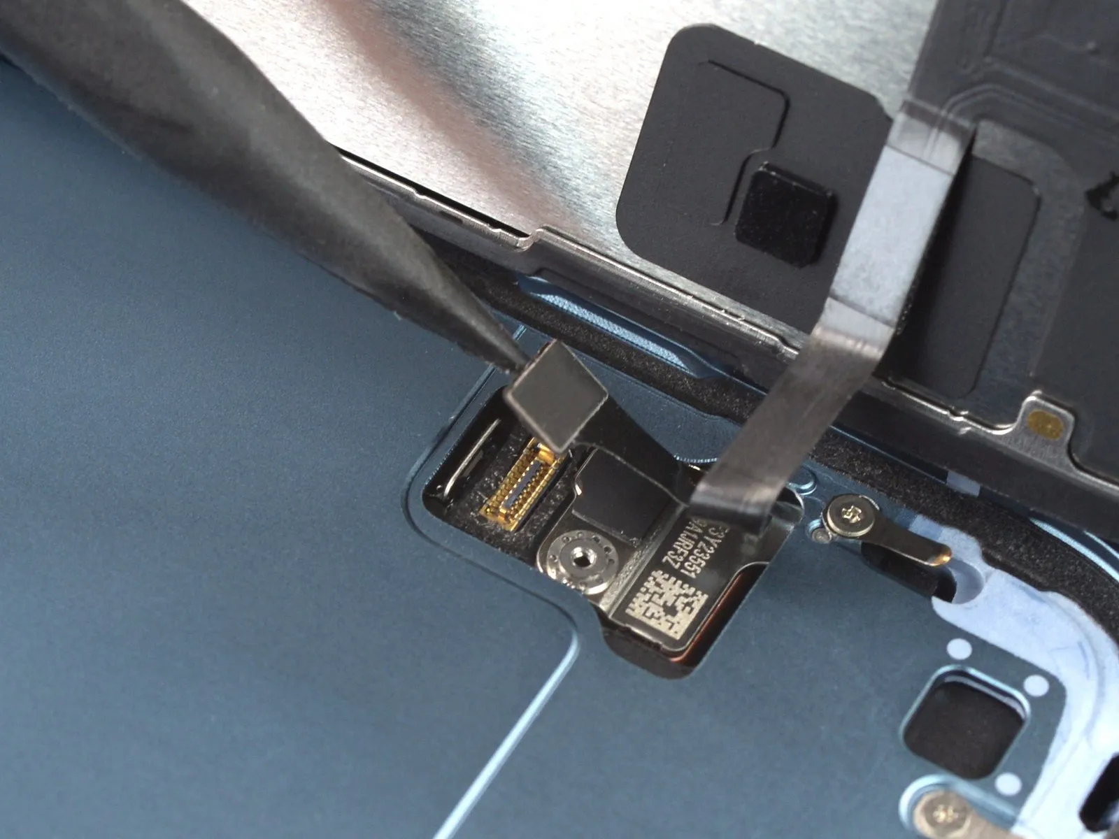
Step 20 | Remove the screen
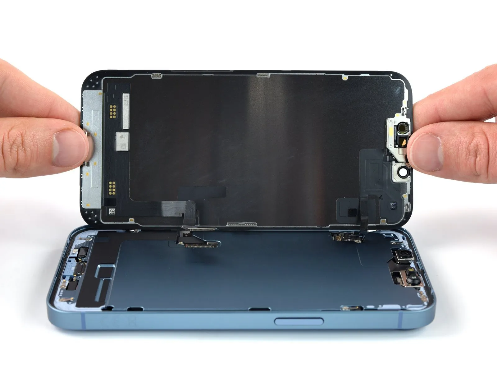
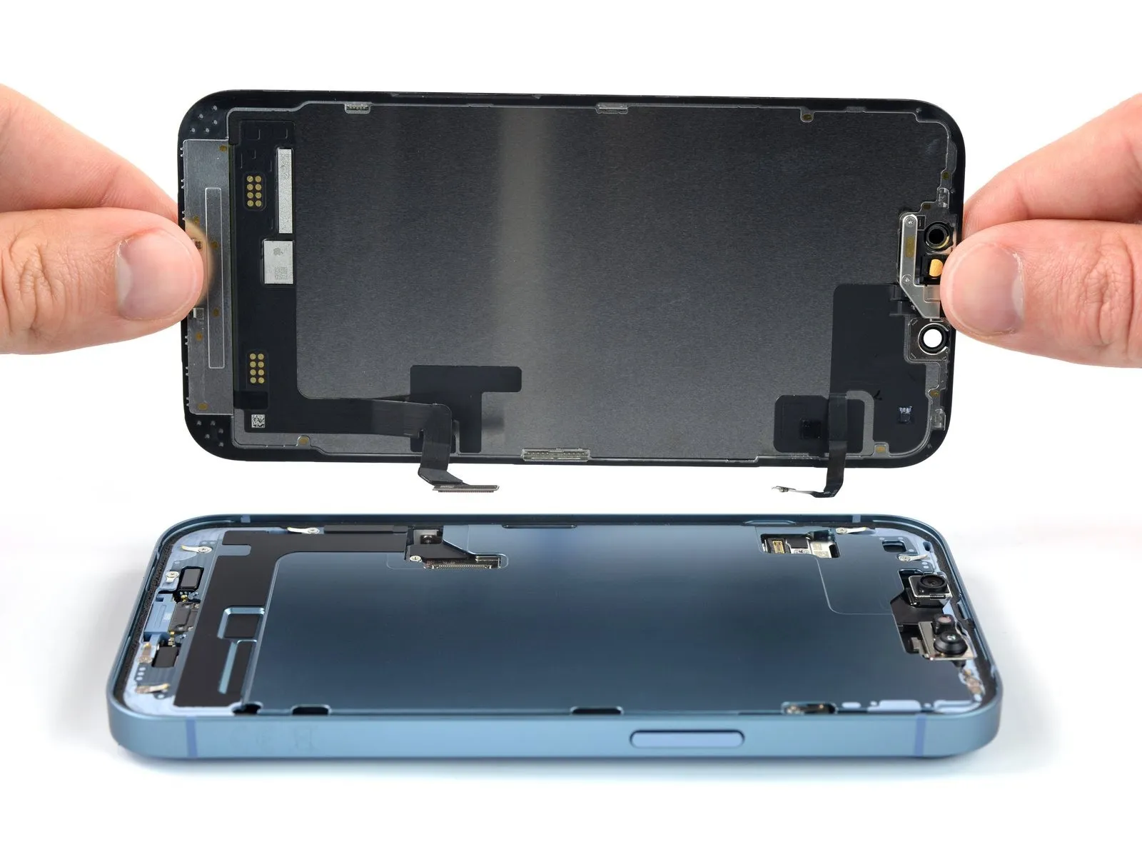
- Detach the display panel from the device’s housing.
- Following a thorough cleaning of the surfaces with isopropyl alcohol exceeding 90% purity, apply fresh adhesive to the required locations.
- If screen adhesive replacement is desired, halt the reassembly process at this stage.
Step 21 | Unfasten the front sensor bracket
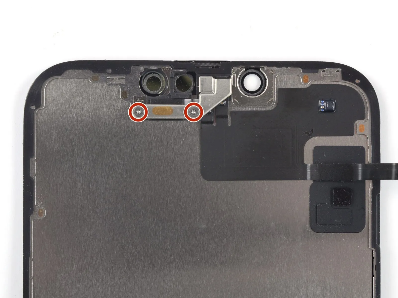
- The subsequent procedures illustrate the process of relocating the front sensor assembly onto a replacement display panel.
- Employ a Y000 screwdriverto detach the two screws, each measuring 1.4 millimeters in length, which fasten the sensor assembly bracket.
Step 22 | Remove the front sensor bracket
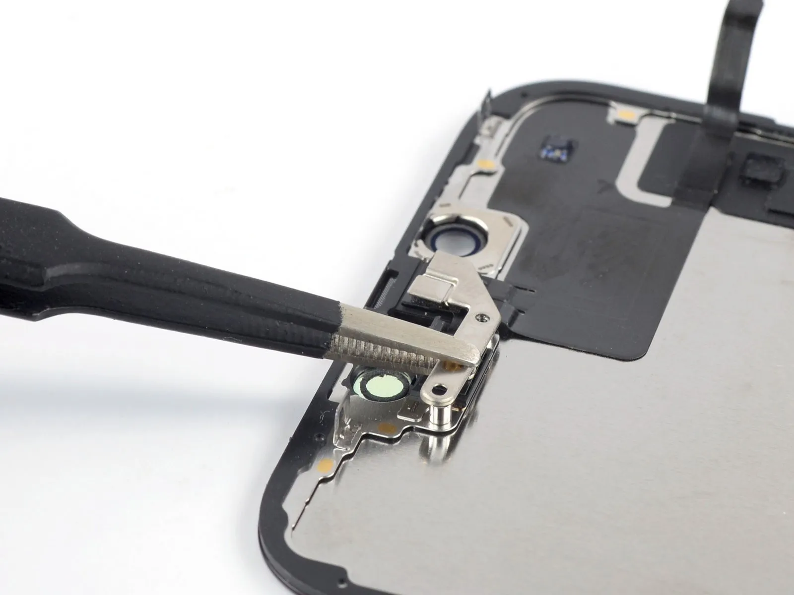
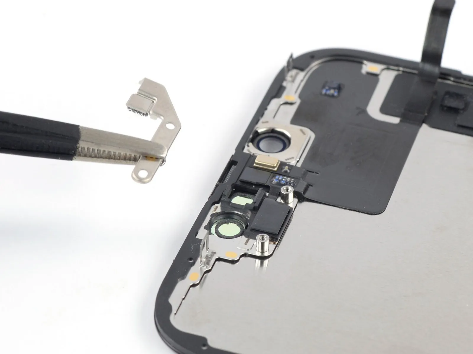
- Employ tweezers or manual dexterity to detach the securing bracket that holds the front sensor assembly in place.
Step 23 | Heat the front sensor assembly

- Employing a device such as an iOpener, warmed to a suitable temperature, position it against the screen's upper boundary and maintain contact for a duration of two minutes.Alternative heat sources, including hair dryers, heat guns, or hot plates, can be utilized, however, exercise caution to prevent excessive heat exposure, as the display panel is vulnerable to thermal degradation.The application of heat softens the adhesive securing the screen, facilitating its subsequent removal.
- Overheating the device may result in irreversible damage to the display; therefore, careful temperature regulation is essential throughout this procedure.
Step 24 | Disconnect the ambient light sensor
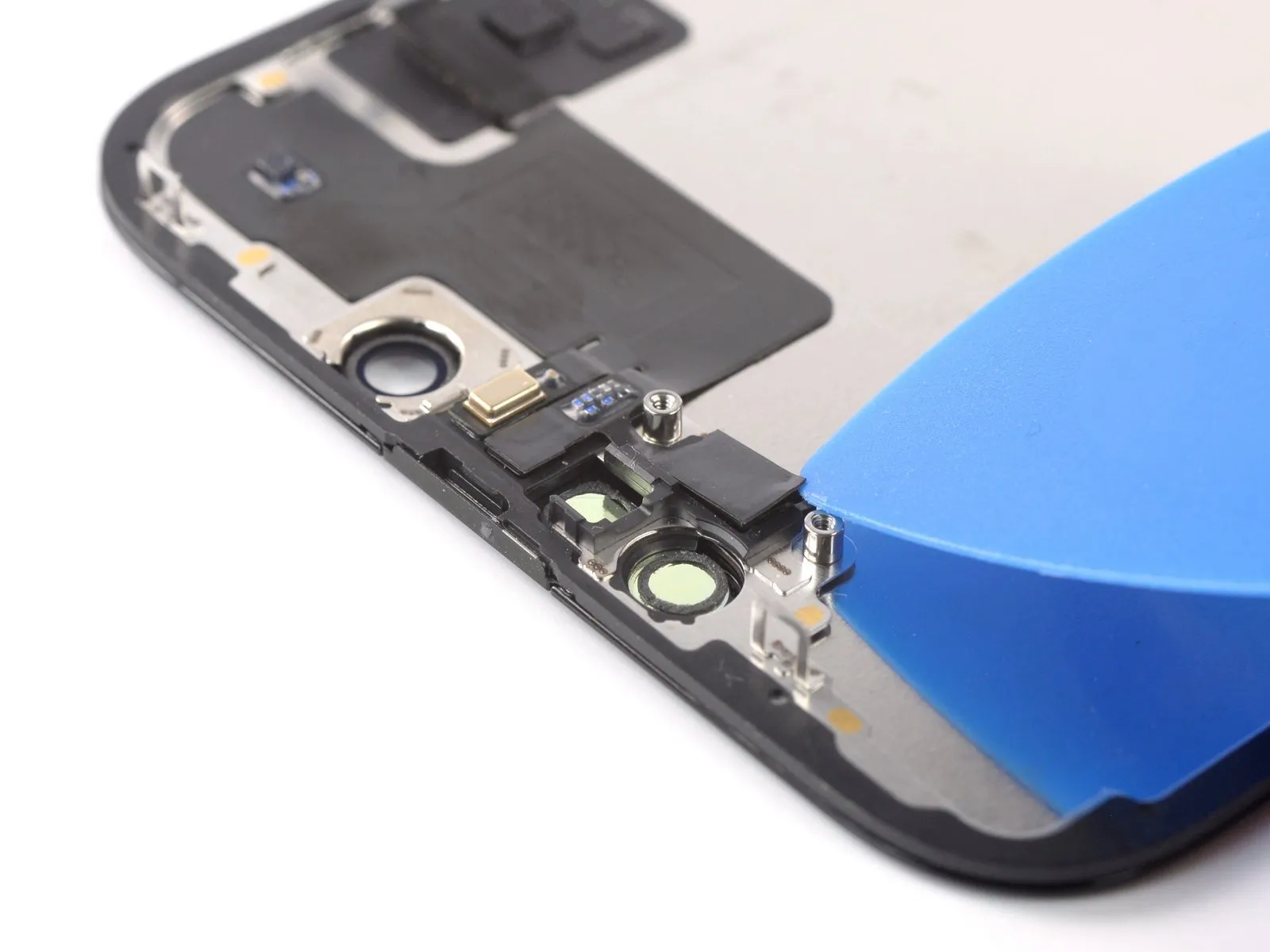
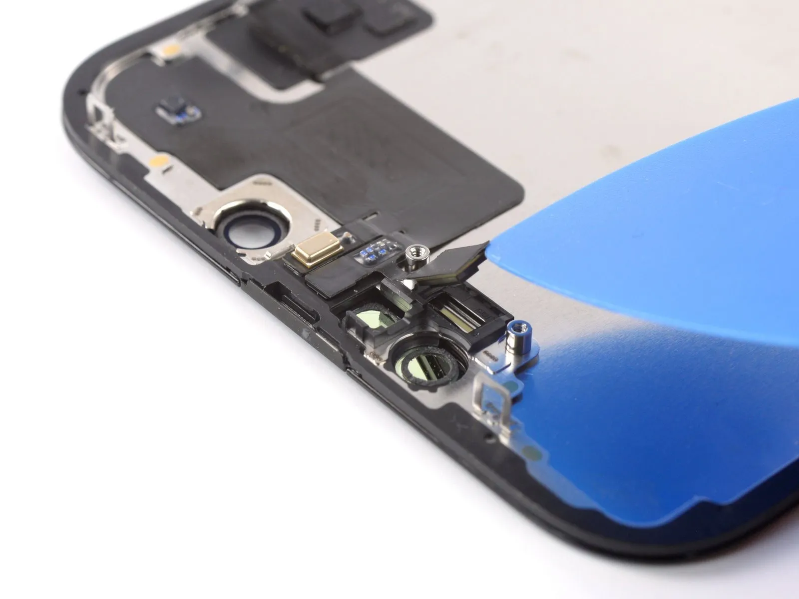
- Position a specialized opening tool within the gap located between the ambient light sensor and its designated housing within the display assembly.The tool should be carefully inserted to facilitate separation.Apply gentle lifting force using the opening tool to disengage the ambient light sensor from the screen's surface.
- This action creates a space allowing for subsequent component removal, ensuring the sensor is detached without damage.
Step 25 | Disconnect the proximity sensor
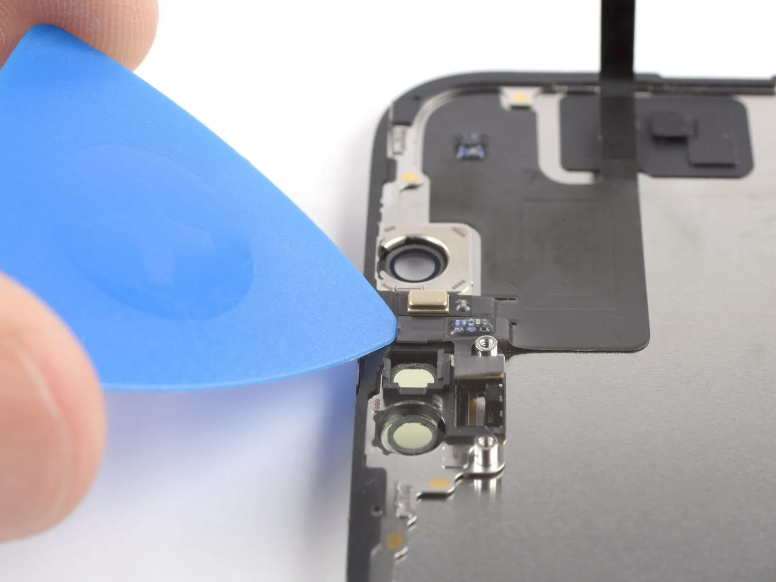
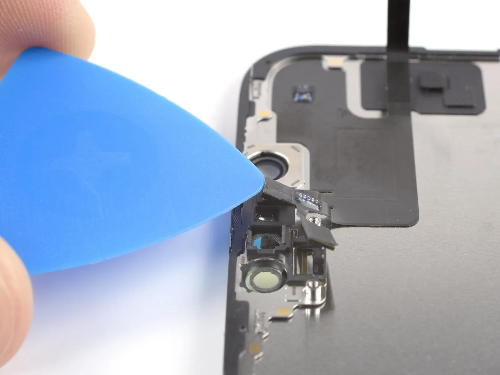
- Position a prying tool within the gap located between the proximity sensor and the surrounding indentation on the display assembly.
- Apply upward force using the prying tool to disengage the proximity sensor from the screen surface.
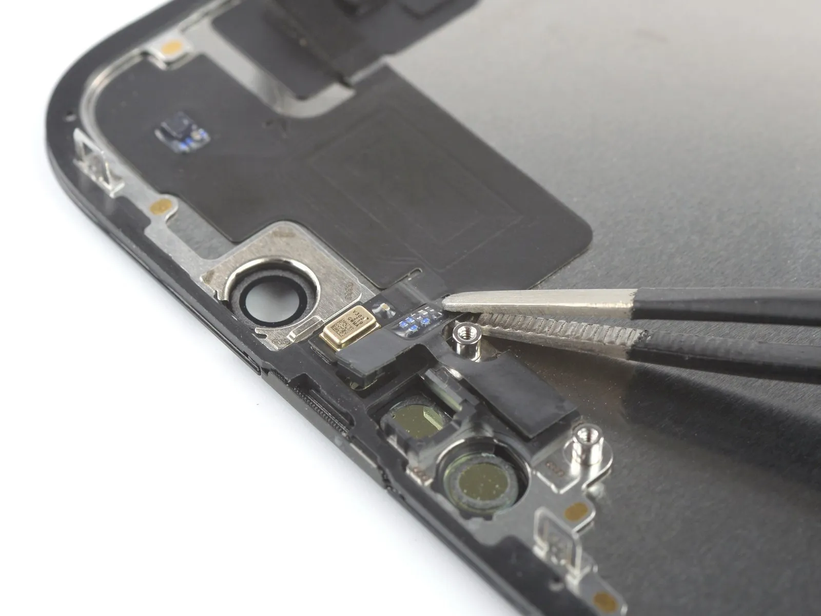
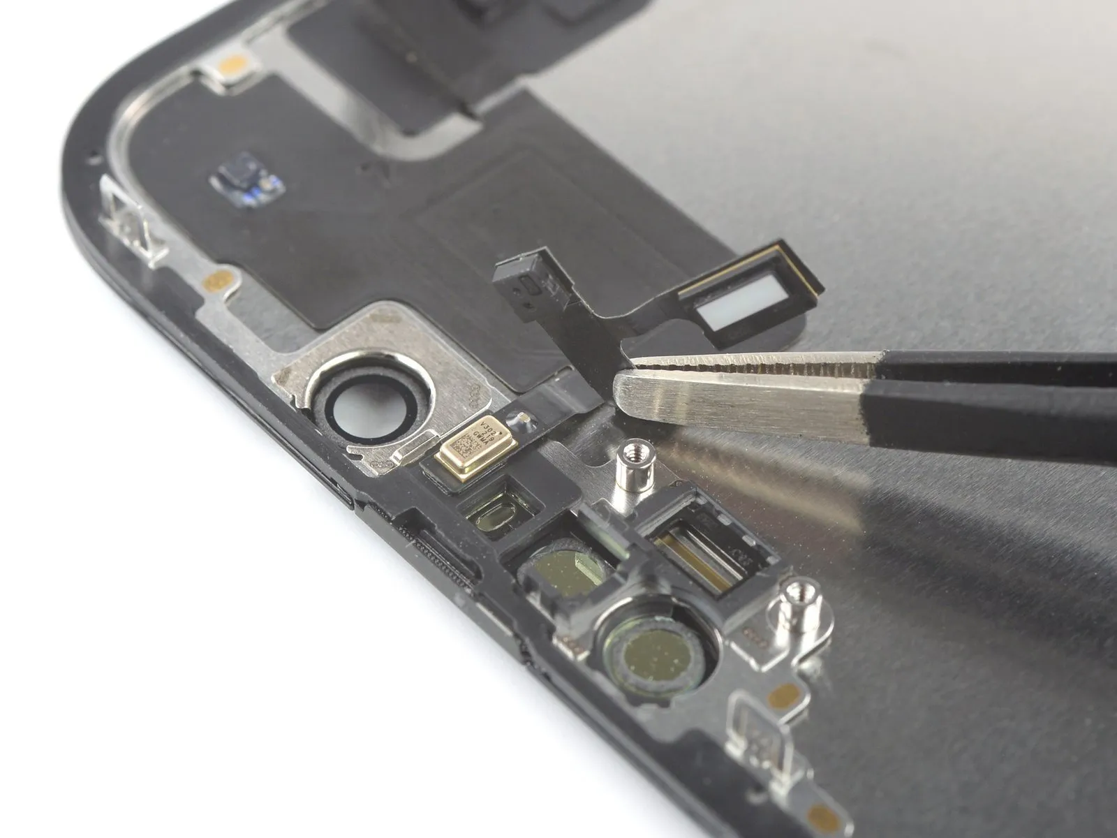
Step 26 | Reposition the proximity sensor
Step 27 | Disconnect the microphone
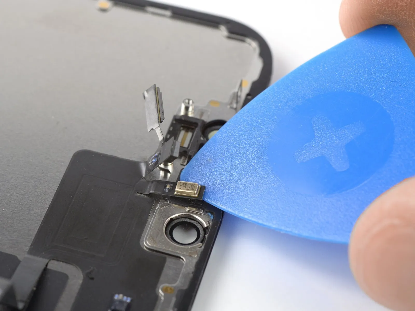
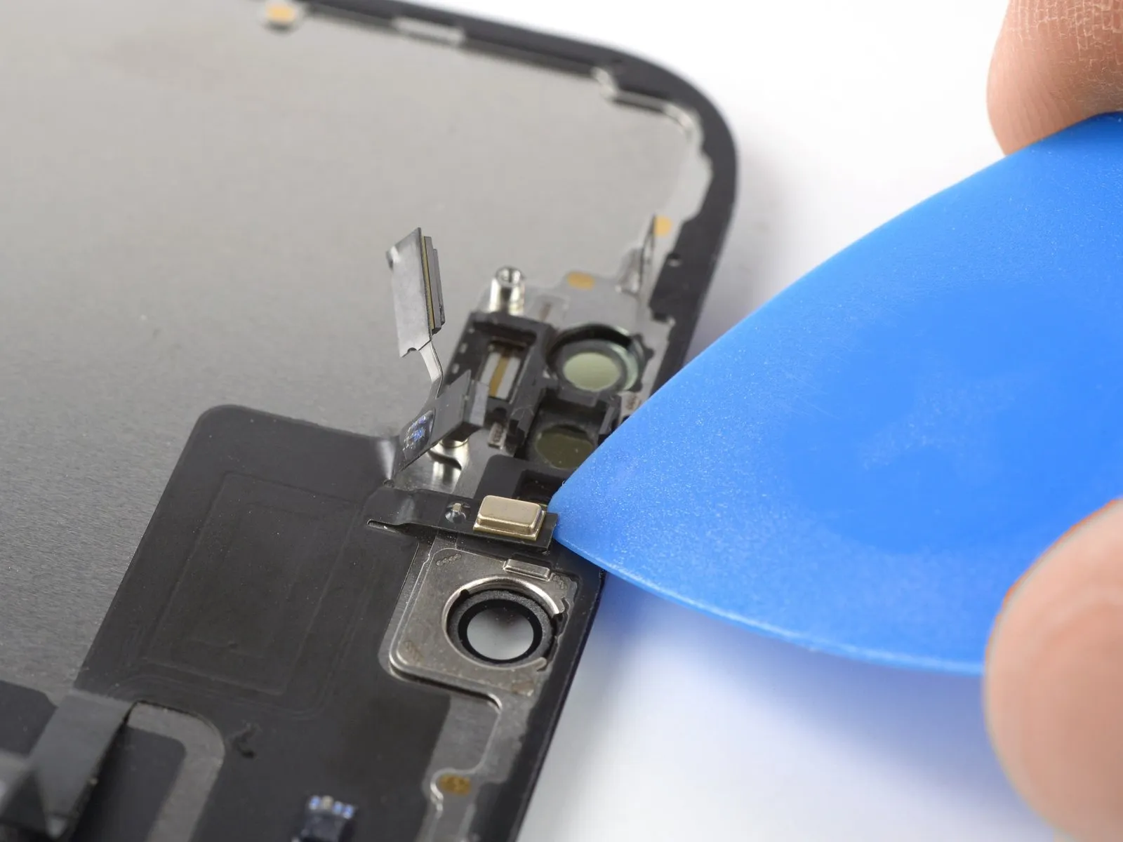
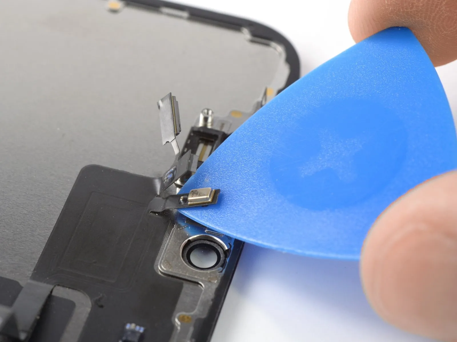
- Position a prying tool beneath the microphone cable's connection point, situated near the microphone's metallic housing.
- Move the prying tool along the microphone's edges to detach the adhesive securing it.
Step 28 | Remove the front sensor assembly
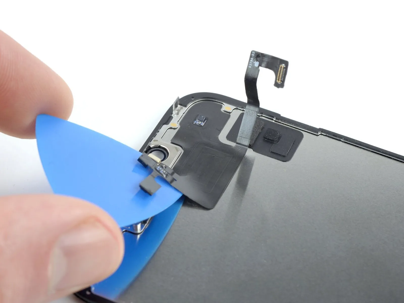
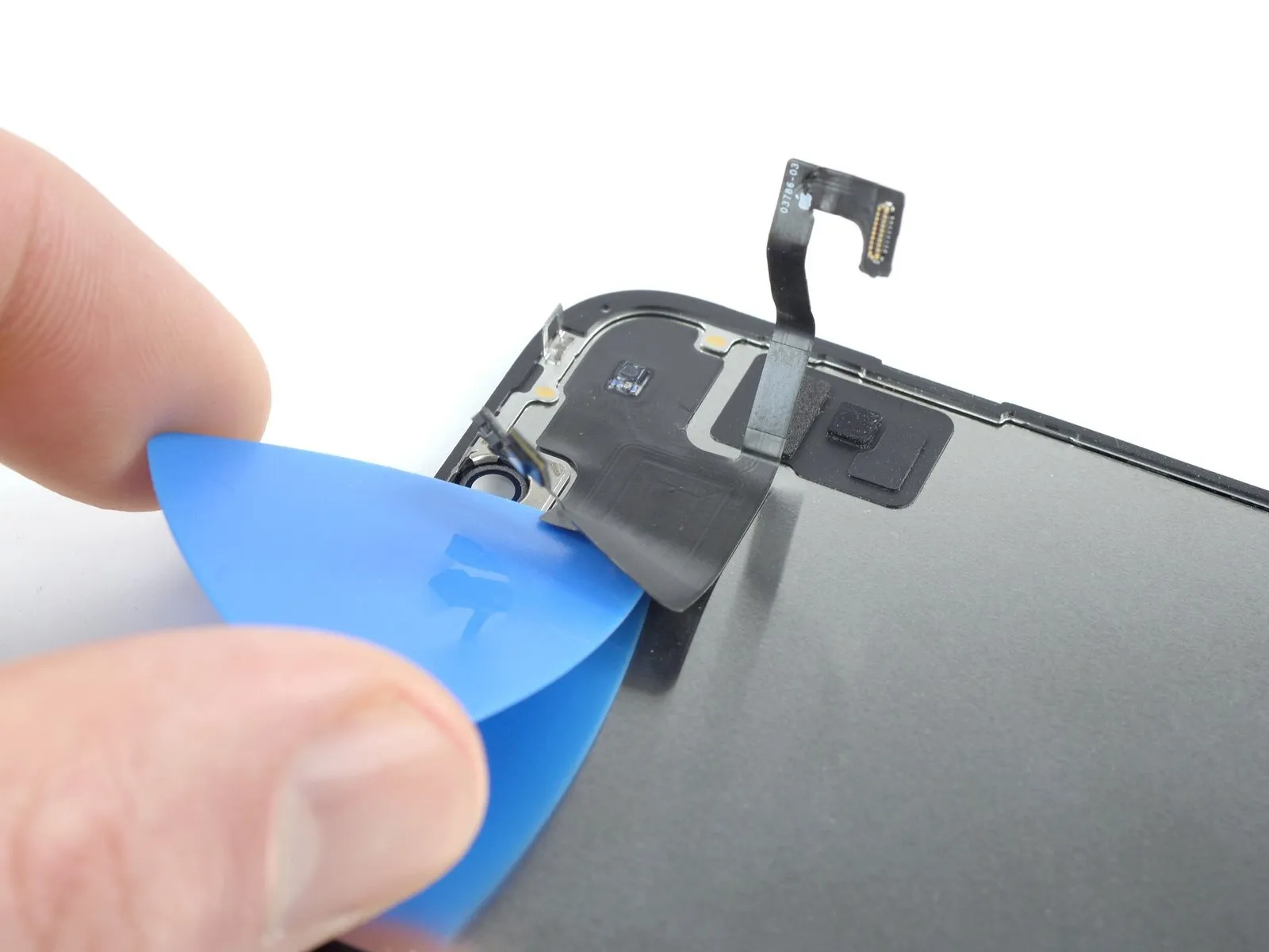
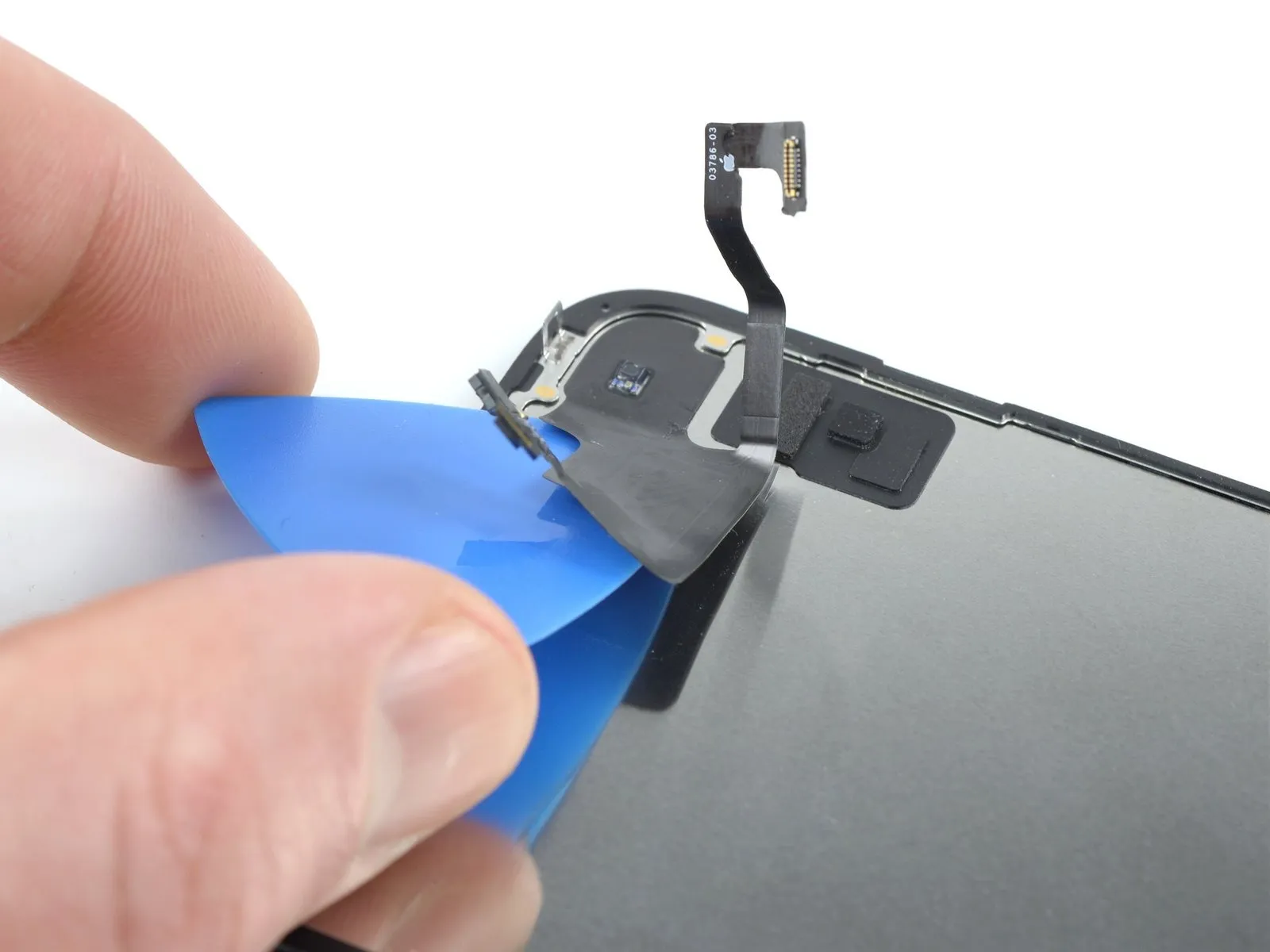
- Should the adhesive have solidified by this stage, utilize a heated iOpener on the device for a duration of sixty seconds to soften it prior to proceeding.
- Introduce an opening pick beneath the left edge of the front sensor assembly to initiate separation.
- Advance the pick to create a gap and disengage the assembly from the device frame.
Step 29
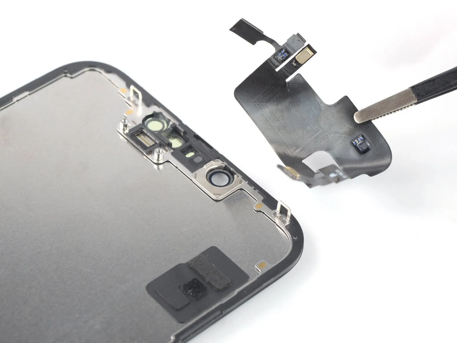
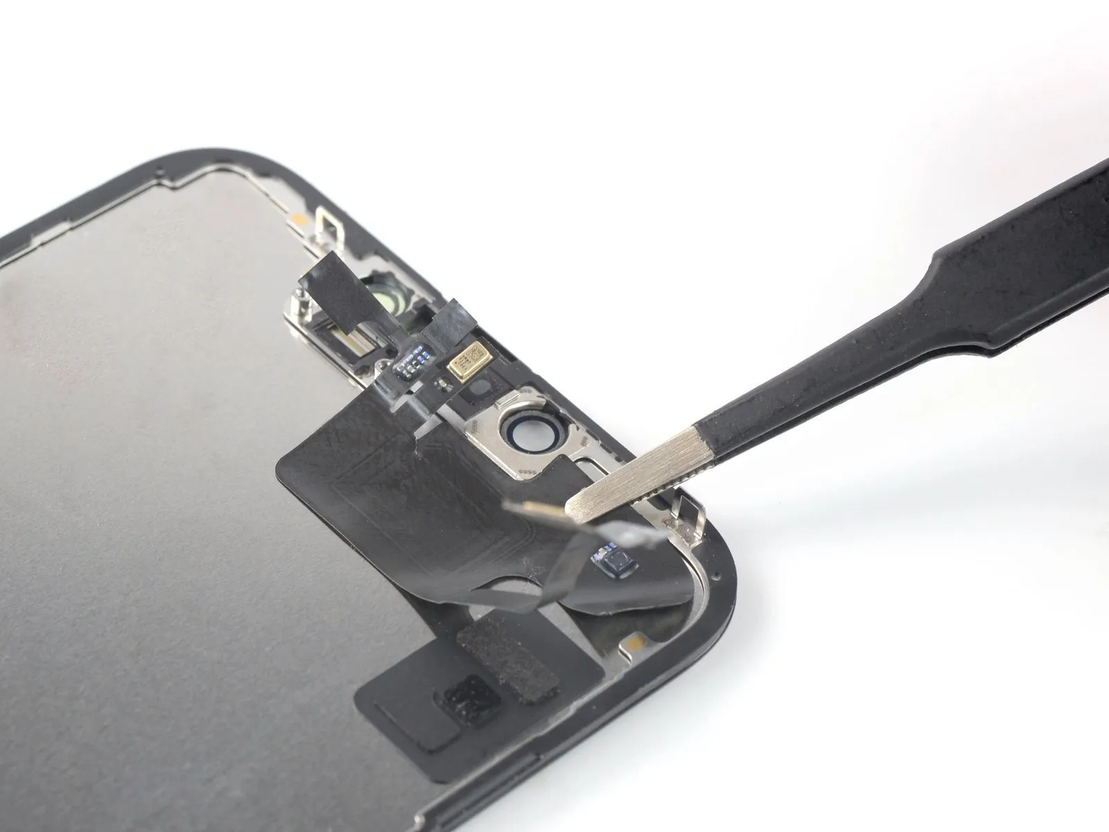
- Detach the front sensor unit.
- Adhere to the following procedure when relocating the sensor assembly to a replacement display panel.
- Position the sensor connectors within the frame's designated receptacles to facilitate accurate alignment of the primary assembly component.
- Re-secure any detached adhesive portions of the assembly by applying Tesa tape.