iPhone 14 Pro Front-Facing Camera Assembly Replacement
This document provides instructions for the removal and replacement of the front camera module on an iPhone 14 Pro.
The creation of this guide was based on the A2890 model, which is the international variant; while other iPhone 14 Pro models may exhibit slight visual differences, the repair steps remain consistent.
- The front-facing camera and Face ID components are integrated into a single assembly, with the sensors specifically matched to the device's logic board.
- Important considerations are listed below.Substituting this component will result in the loss of Face ID functionality.
- Replacing a damaged front-facing camera will restore its operation; however, on iOS versions 17.6 and earlier, Face ID reactivation requires Apple or an Apple-certified technician, whereas iOS 18 and later versions allow for recalibration of genuine replacement cameras using Apple's Repair Assistant.
To ensure proper screen sealing during reassembly, new adhesive is required, and the device's water resistance will be affected by the quality of the adhesive application, resulting in a loss of the official IP rating.
Step 1 | Remove the pentalobe screws
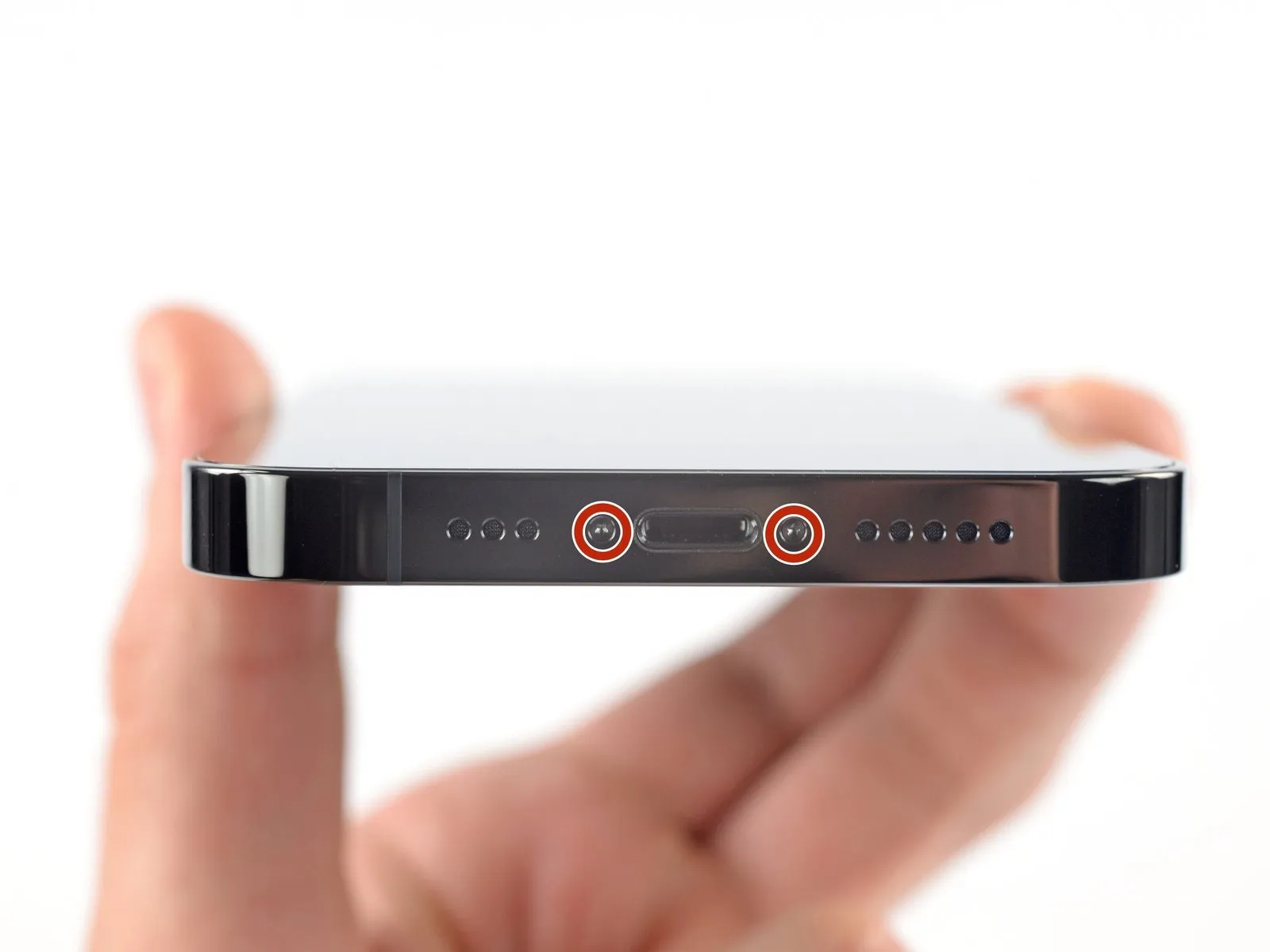
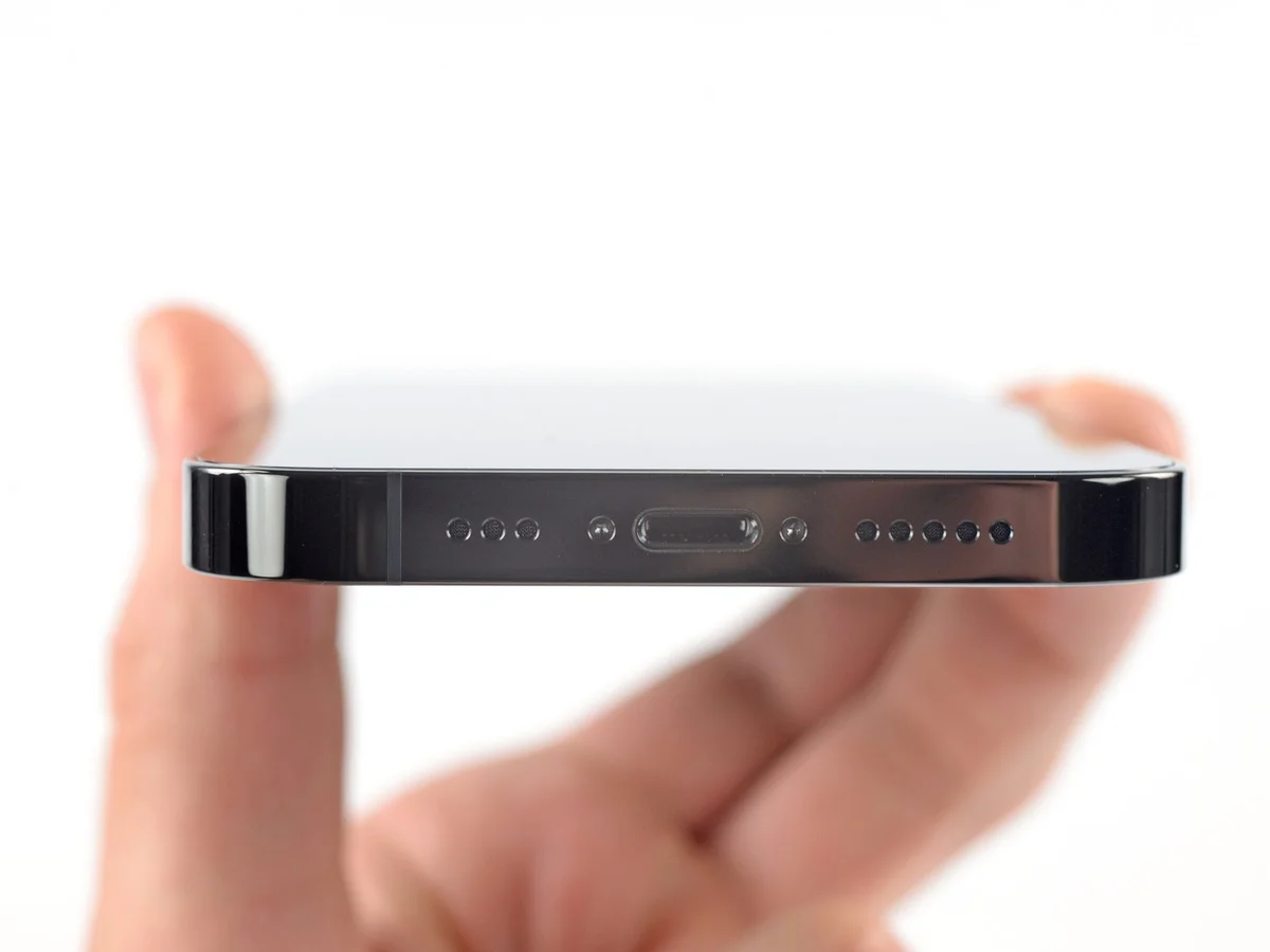
- Prior to commencing the iPhone's disassembly process, ensure the device is completely powered down.
- The two pentalobe P2 screws, each measuring 6.8 millimeters in length, must be detached.These screws are located along the lower perimeter of the iPhone's casing.Careful removal of these fasteners is essential for proceeding with the repair.
Step 2 | Mark your opening picks


- Excessive insertion of a pick can potentially harm the device; therefore, it is crucial to implement a marking procedure to avoid such damage.
Using a measuring tool, determine a distance of3 millimetersfrom the pick's tip and use a permanent marker to create a visible indication on the pick. - To further enhance precision, consider marking the remaining corners of the pick with varying measurement distances.
- As an alternative method, affixing a coin to the pick, positioned 3 millimeters from the tip, can also serve as a depth indicator.
Step 3 | Tape over any cracks


- To mitigate additional damage and potential injury when addressing a fractured iPhone display, secure the broken glass with adhesive tape.
Apply successive layers of transparent packing tape across the iPhone's screen surface, ensuring complete coverage of the display's front. - Protect your vision by utilizing safety eyewear, guarding against potential glass fragments that may detach during the repair process.
- Should the suction cup fail to maintain adhesion during subsequent procedures, construct a handle from a robust tape, like duct tape, to facilitate screen lifting.
- As a last resort, secure the suction cup to the screen's surface using superglue to establish a stable grip.
Step 4 | Anti-Clamp instructions


The subsequent three actions illustrate the Anti-Clamp, a specialized tool developed to simplify the initial separation process; if this tool is unavailable, proceed to the instructions three steps later for an alternative approach.
Detailed guidance regarding the Anti-Clamp's operation can be found in a separate, comprehensive instructional document.
- Grasp the blue handle and draw it in a rearward direction to disengage the locking mechanism of the Anti-Clamp's supporting arms.
- Carefully position the arms across either the left or right side of your iPhone's frame.
- Place the suction cups in proximity to the lower edge of the iPhone, ensuring one is situated on the front surface and the other on the rear.
- Apply pressure by compressing the cups together, thereby creating a secure adhesion to the intended location.
- Should the iPhone's surface exhibit excessive slipperiness, hindering the Anti-Clamp's ability to maintain grip, applying adhesive tape can provide a more textured interface.
Step 5


- Advance the blue handle to engage the locking mechanism on the arms.
- Rotate the handle a full 360 degrees, or continue until the cups exhibit signs of deformation.
- Maintain the precise alignment of the suction cups; should misalignment occur, slightly release the suction cups and readjust the arms.
Step 6


- Employ a hair dryer to apply warmth along the iPhone's lower edge, aiming for a temperature just beyond comfortable touch.
- Refer to a dedicated guide for detailed instructions on the proper operation of a hair dryer.
- Allow a sixty-second interval to permit the adhesive to soften and create a discernible separation.
- Once a noticeable gap appears, carefully introduce an opening pick beneath the screen's plastic bezel.
- Should the Anti-Clamp fail to generate an adequate separation, increase the heat locally and rotate the handle incrementally by ninety degrees.
- Avoid excessive rotation, limiting adjustments to ninety-degree increments, and pausing for sixty seconds between each rotation to allow the device and time to work effectively.
- Proceed past the following two procedural segments.
Step 7 | Heat the bottom edge

- Apply warmth to the iPhone's lower border utilizing a hairdryer or heat gun, continuing until the surface temperature becomes marginally uncomfortable to the touch.
- Avoid prolonged, localized heat application with the heat gun to prevent component damage.
Step 8 | Insert an opening pick
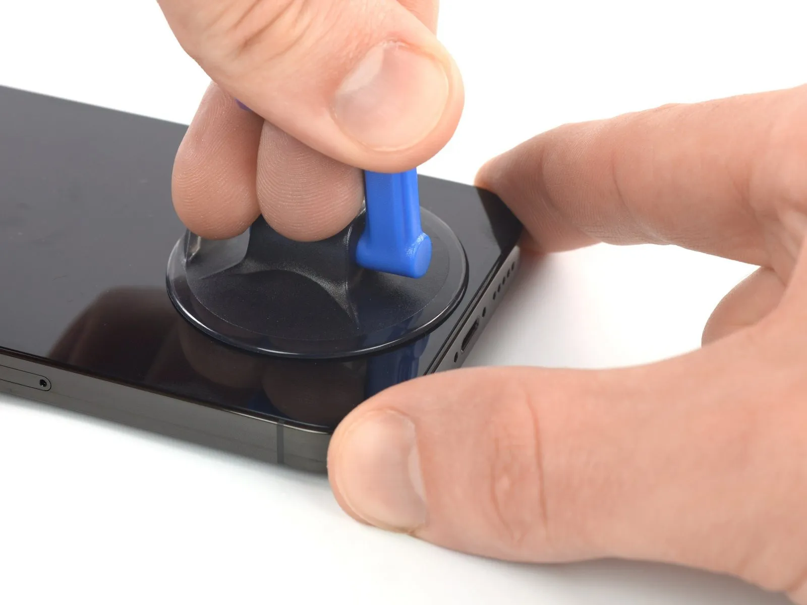
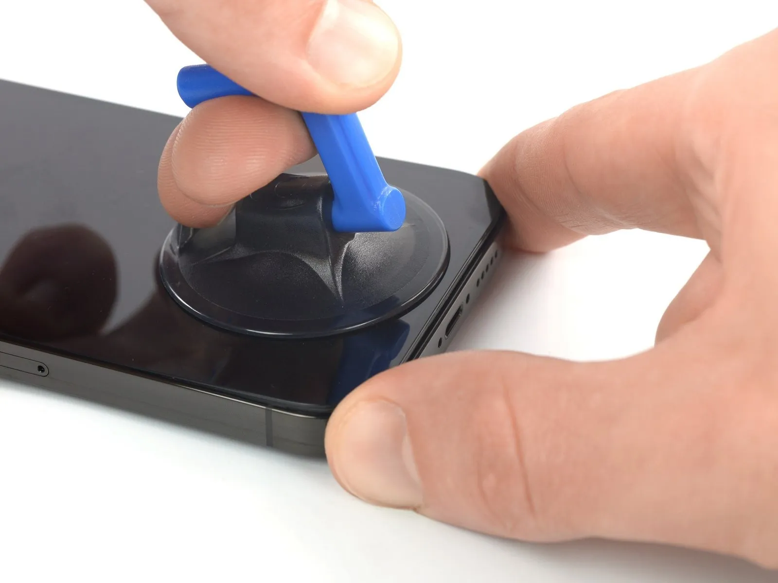
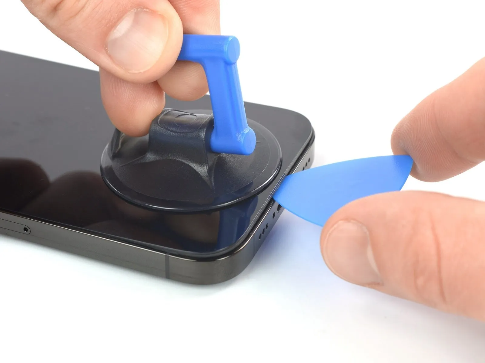
- Maintain steady, consistent upward force on the suction cup to generate a minimal separation between the display and the device's chassis.
- Introduce an opening tool into the space formed beneath the screen's surrounding plastic trim.
- The screen is secured with a robust, waterproof sealant; substantial force may be required to initially disengage the display. If separation proves difficult, apply additional heat and gently oscillate the screen to reduce adhesive strength until a sufficient gap is achieved for tool insertion.
Step 9 | Heat the right edge


Step 10 | Separate the right adhesive

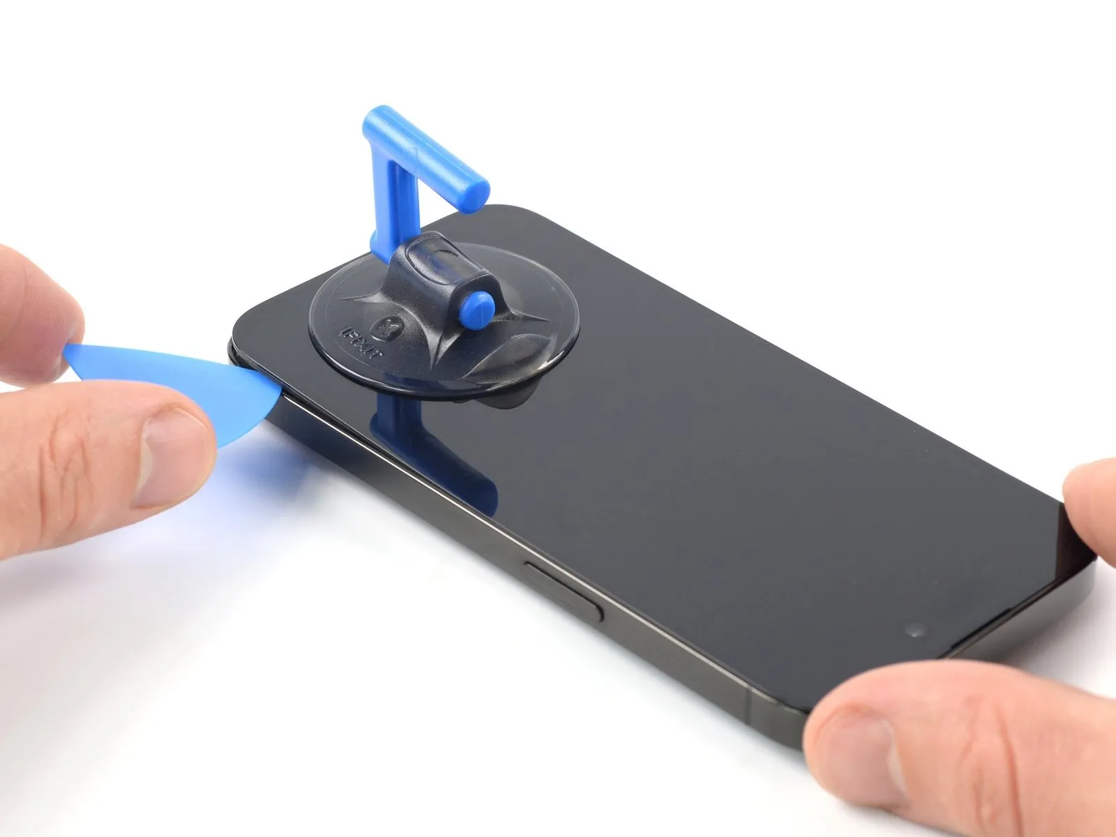
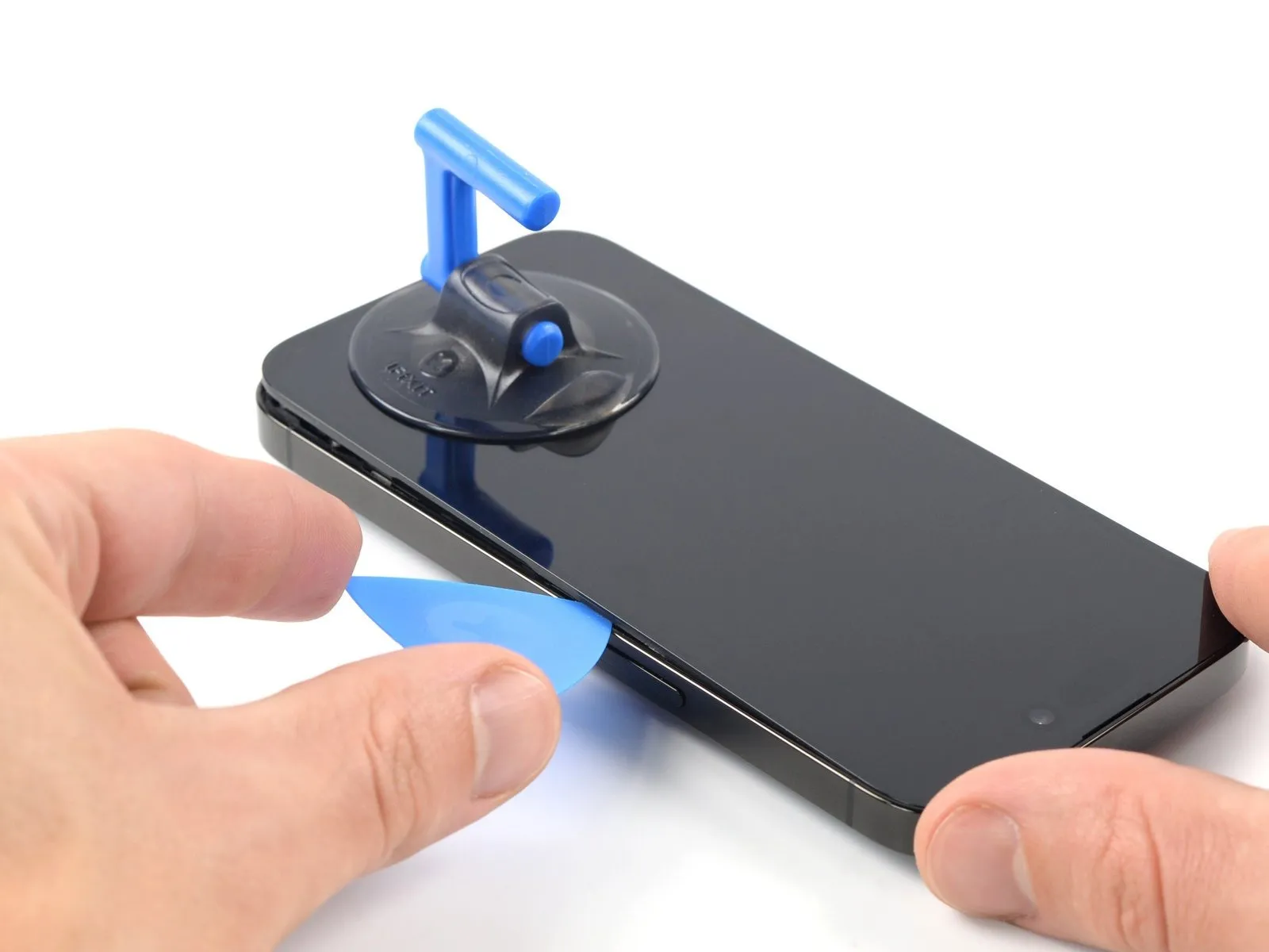
- Utilize a specialized opening tool to maneuver along the lower-right perimeter of the iPhone's enclosure.This action will serve to break the adhesive securing the device's halves.
- Proceed with sliding the tool upward along the right side of the iPhone until the upper-right corner is reached.
- Ensure the opening tool's insertion depth remains below 3 millimeters to prevent potential harm to delicate internal parts.
- Maintain the tool's position at the top-right corner before proceeding with subsequent steps.
Step 11 | Heat the top edge

Step 12 | Separate the top adhesive

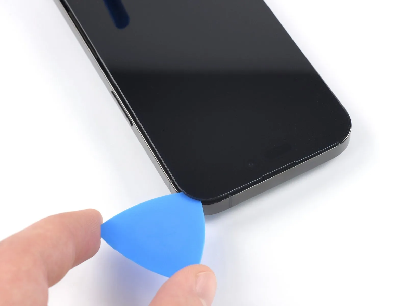
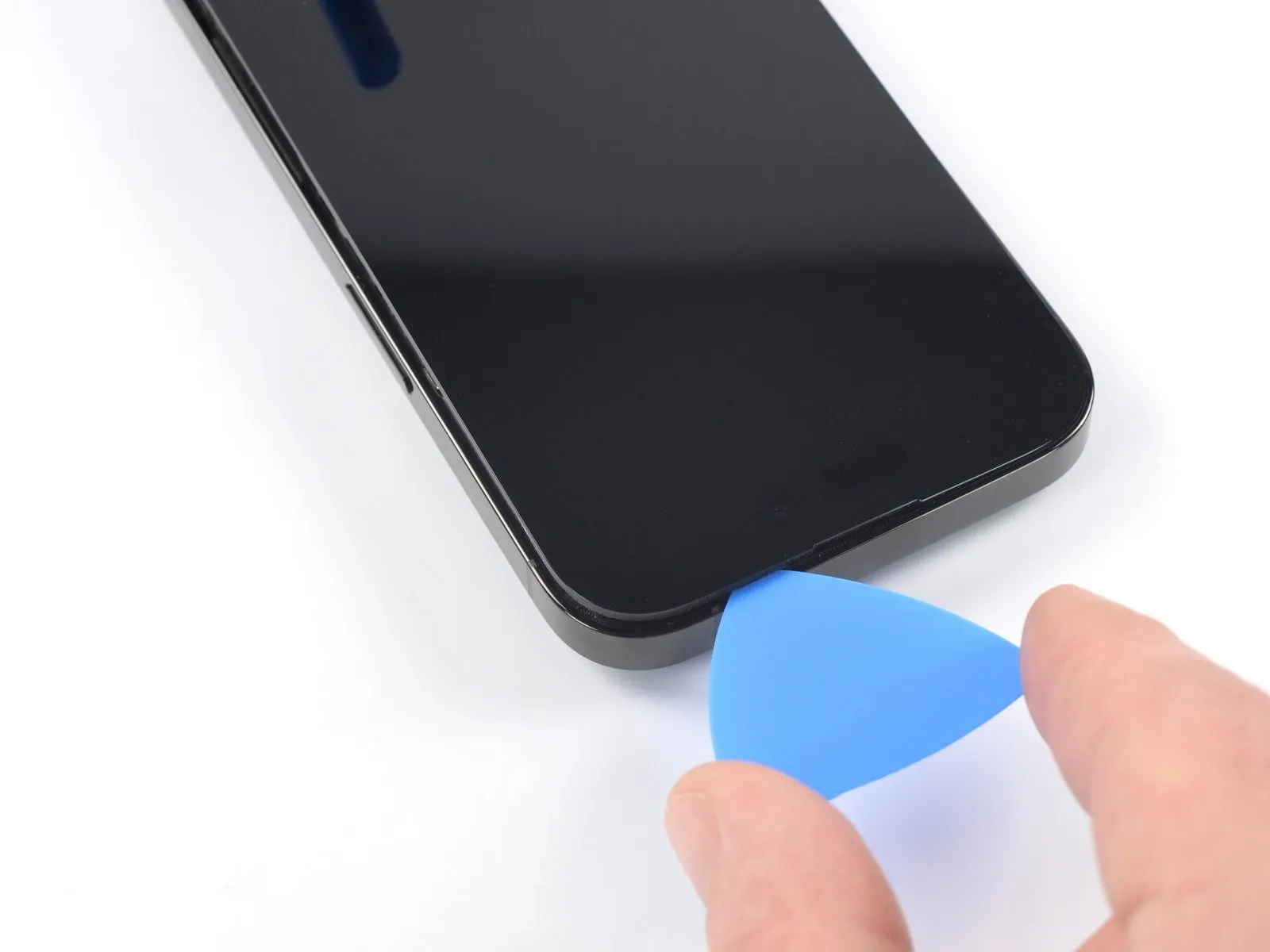
- Employ an opening pick to maneuver along the upper-right edge of the iPhone's casing.This action will serve to detach the adhesive securing the display assembly.
- Insertion depth of the pick should be limited to a maximum of 3 millimeters to prevent potential harm to the proximity and other sensors located at the top of the device.
- Maintain the pick's position within the upper-left corner while proceeding with subsequent steps.
Step 13 | Heat the left edge


Step 14 | Separate the left adhesive


- Fragile wiring is situated along the iPhone's left side; insertion of a tool beyond a depth of 2 millimeters risks cable damage.
- Perform a rotational motion with your tool around the screen's upper-left quadrant.
- Advance your tool along the left edge to the lower corner, releasing the adhesive bond.
- Should adhesive separation prove difficult, apply additional heat to the left edge to soften the bond.
Step 15 | Open the iPhone
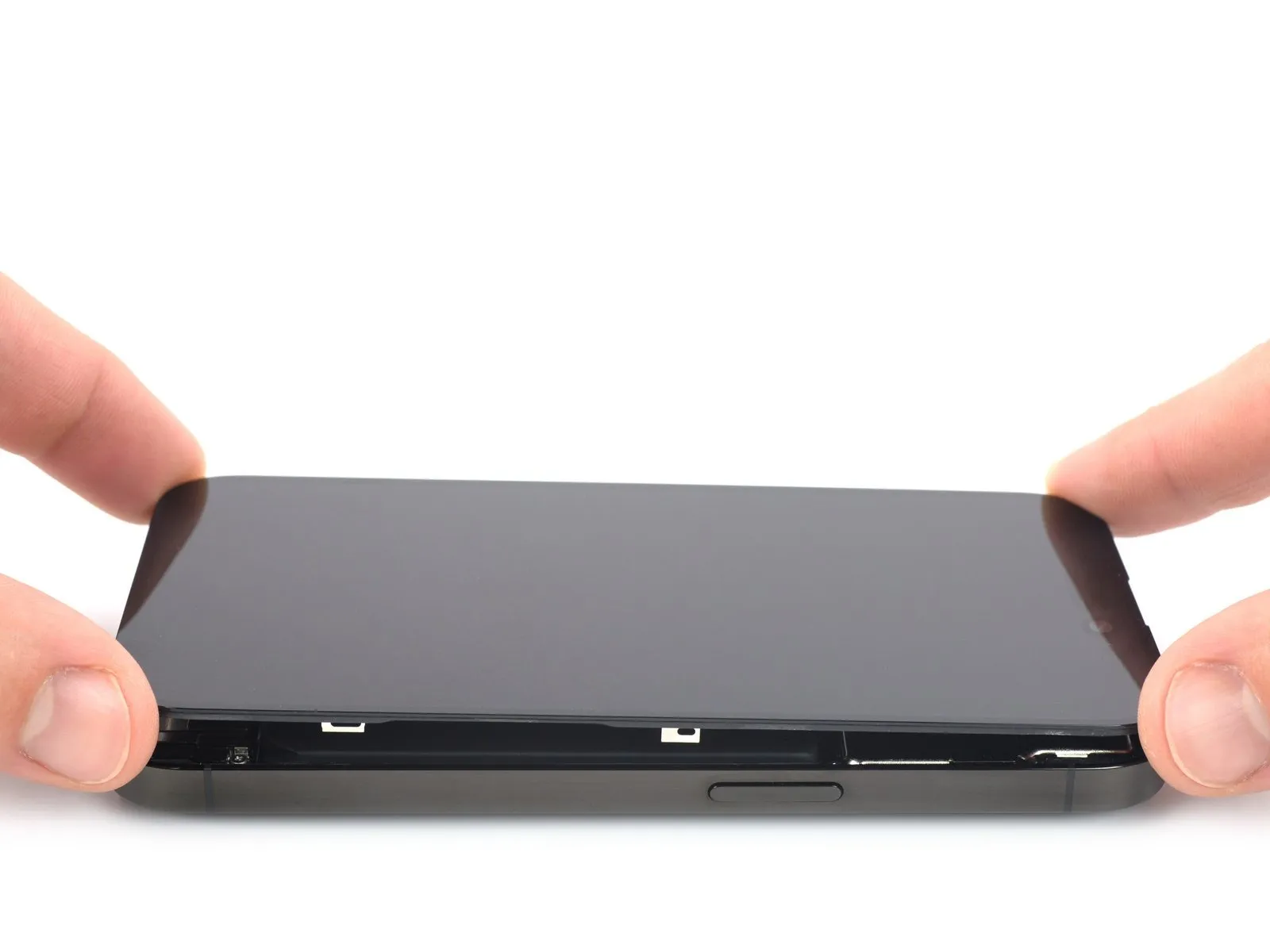
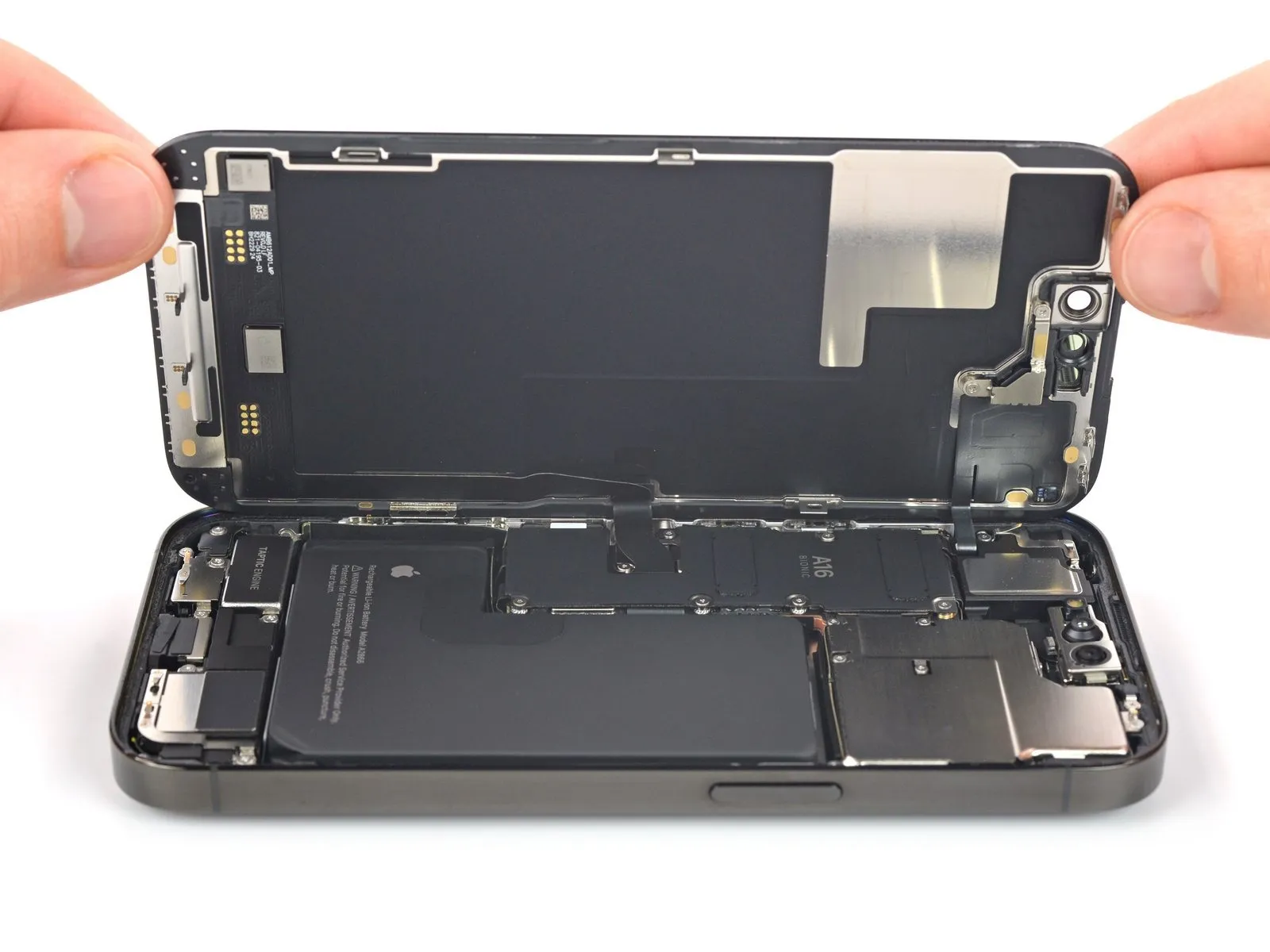
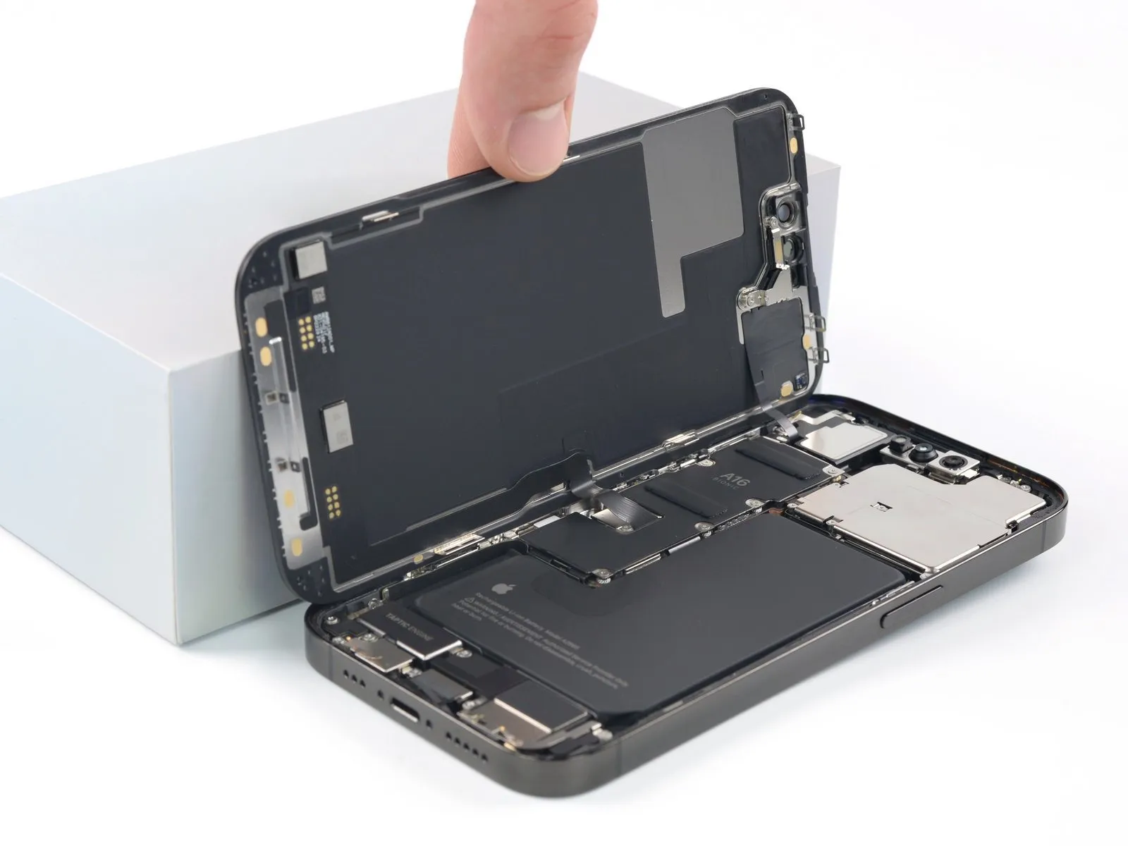
- Detach the suction handle from the display assembly.
- Orient your iPhone, ensuring the right-hand side is visible.
- Separate the iPhone's display from its chassis by pivoting the screen upwards from the right, mimicking the action of opening a book's cover.
- Secure the display in an upright position using a support to maintain access to the internal components.
- Alternatively, the suction handle can be utilized to brace the display if a separate support is unavailable.
When reattaching the display, position it correctly, match the alignment of the clips situated on the upper edge, and apply gentle pressure to the top edge before fully securing the display, verifying that all clips are free from deformation and properly aligned around the screen's boundary.
Step 16 | Unfasten the battery connector cover screws
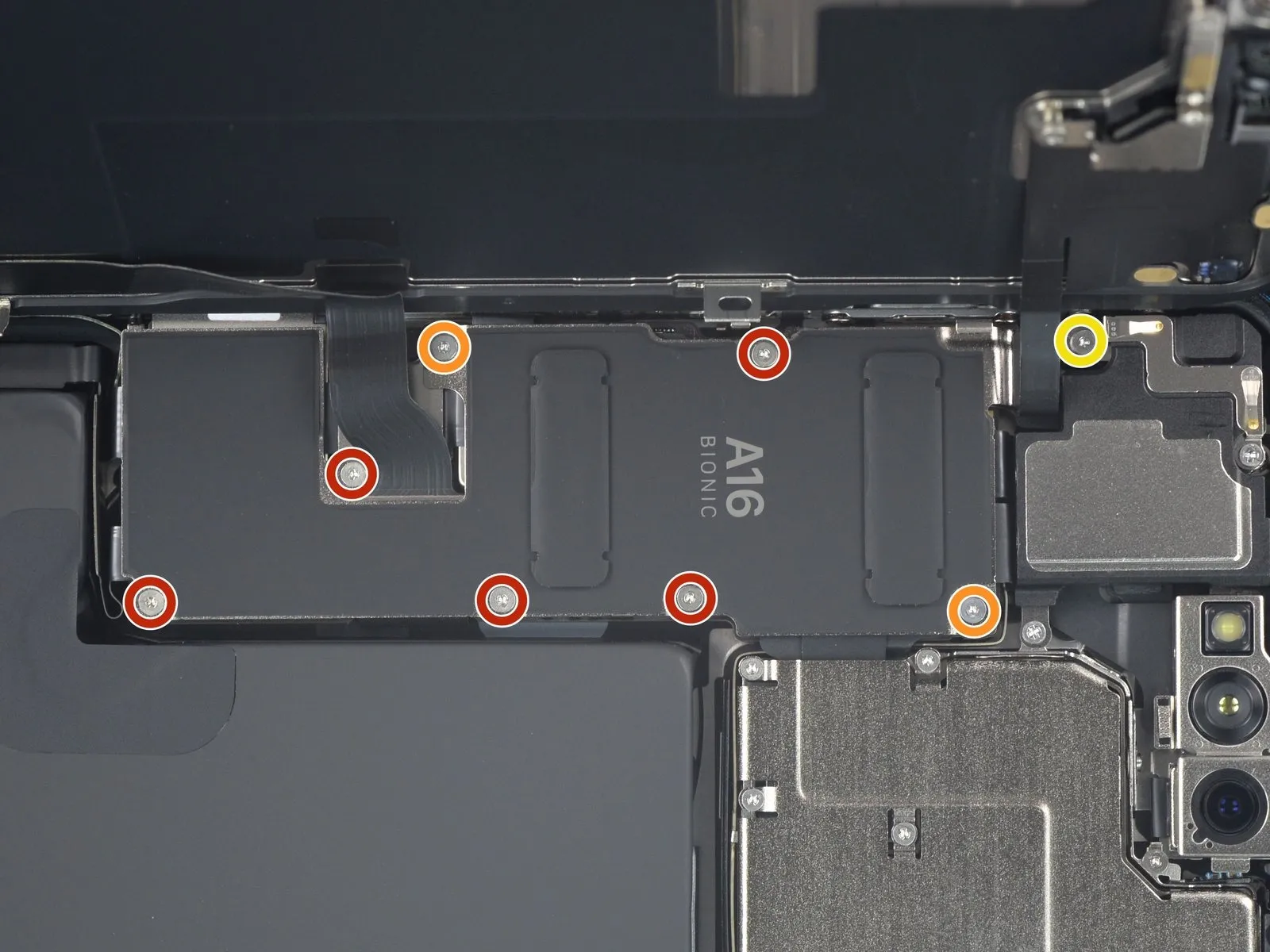
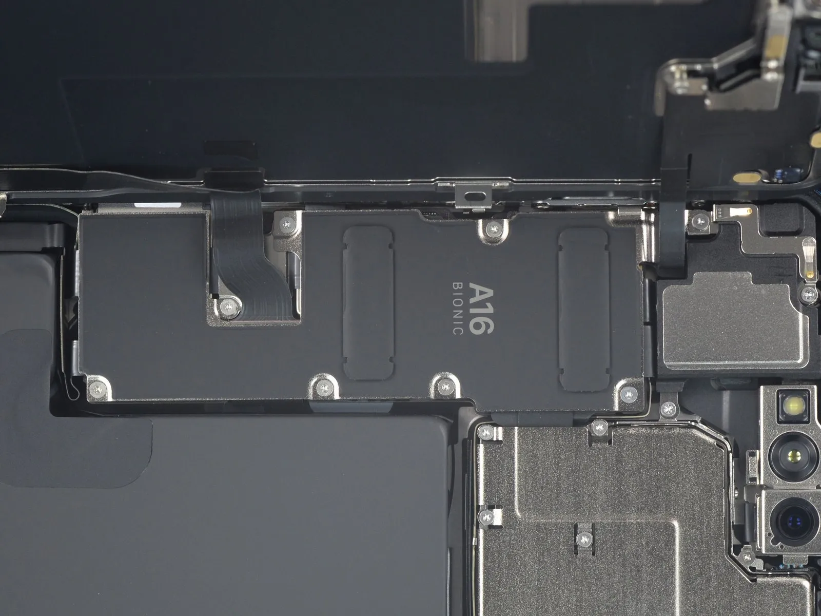
- Employ a Y000 screwdriver to detach the eight screws that fasten the battery connector cover.
- A quantity of five screws, each measuring 1.3 millimeters in length, are present.Two screws, each with a length of 1.6 millimeters, are also included.A single screw, measuring 1.9 millimeters in length, completes the set.
- Carefully monitor the location of each screw during disassembly to ensure correct placement during reassembly, preventing potential damage to the iPhone.As a verification step during reassembly, it is advisable to briefly activate the iPhone and confirm all functionalities are operating correctly.Prior to securing the display, completely deactivate the iPhone to prevent data loss or system instability.
- This stage provides an opportune moment for preliminary functional testing.Ensure all system operations are verified before proceeding further.Proper screw management is essential for a successful repair.
A complete power cycle is necessary before continuing the reassembly process.
Confirm the iPhone is fully powered off before resuming work.
Step 17 | Remove the battery connector cover
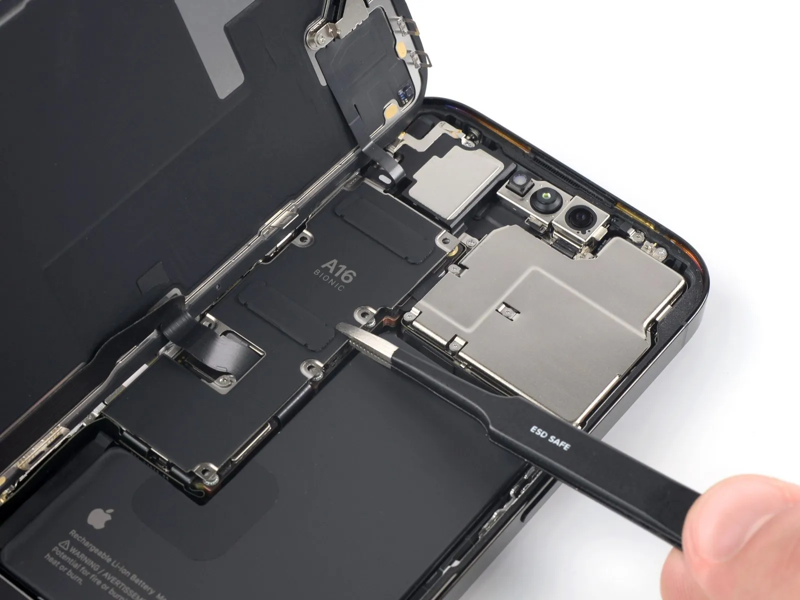
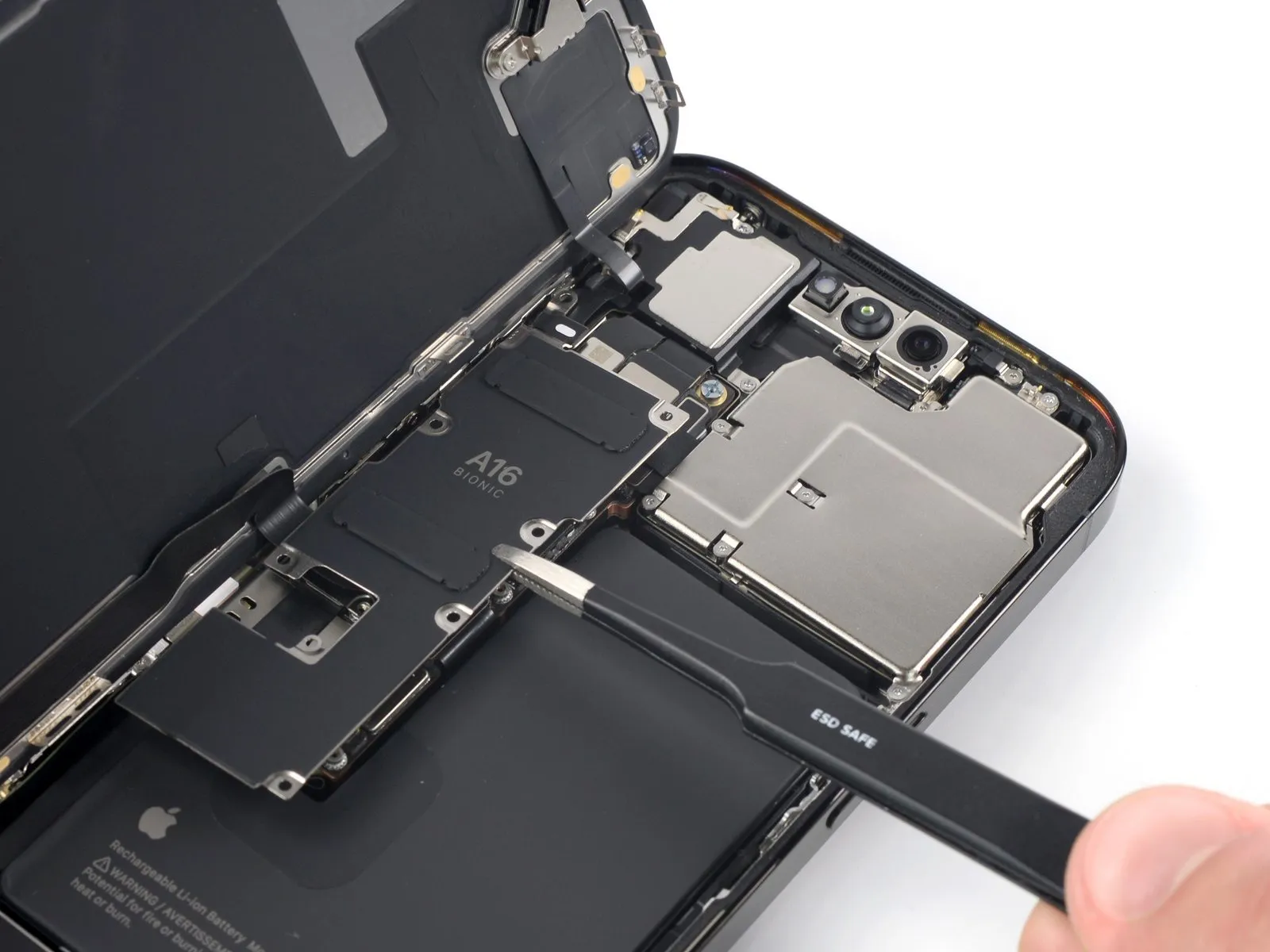
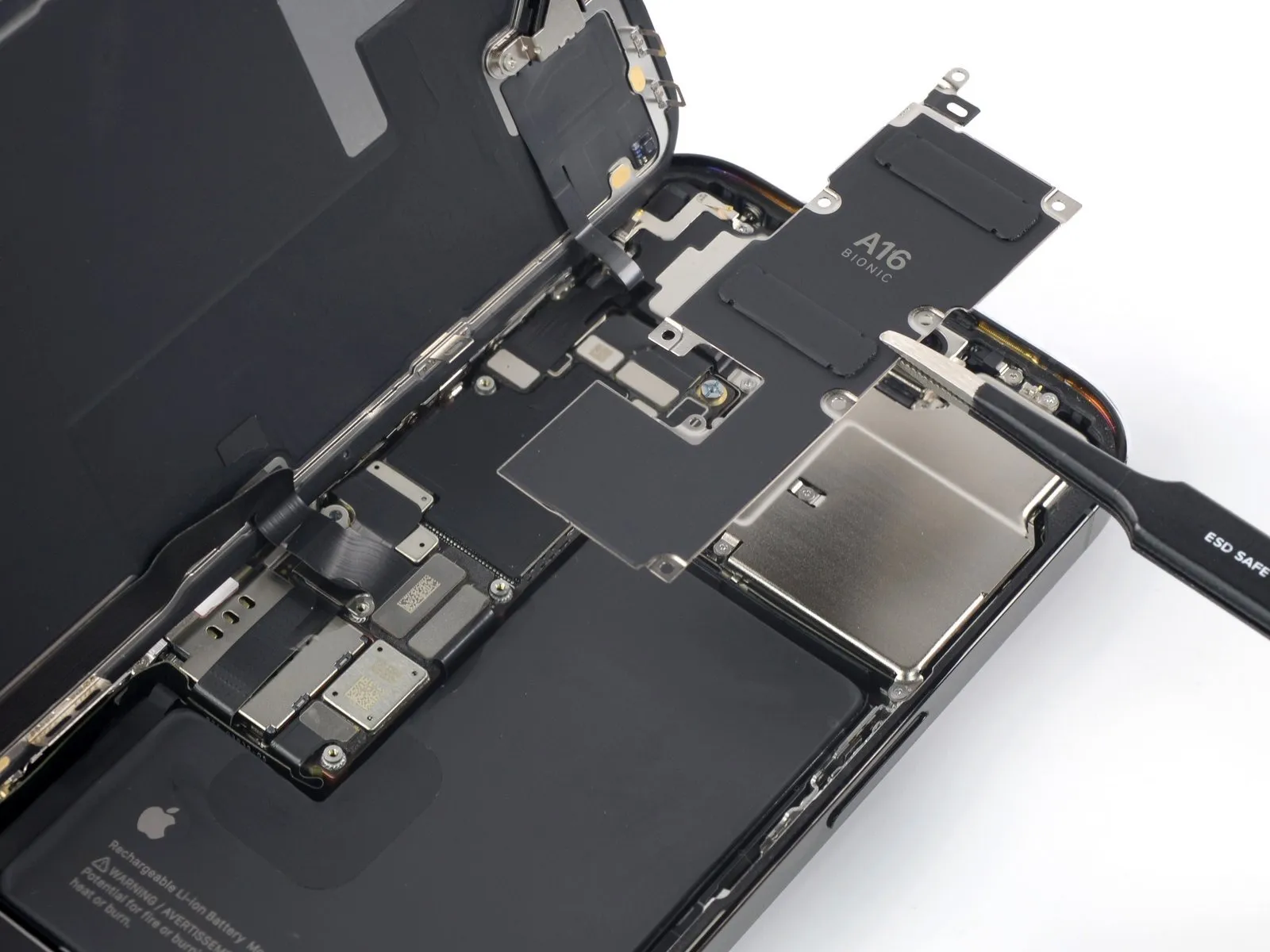
- To permit access to the flexible circuits, advance the connector cover in a downward motion, disengaging it from its position.
- The connector cover should now be completely detached from the assembly.
Step 18 | Disconnect the battery
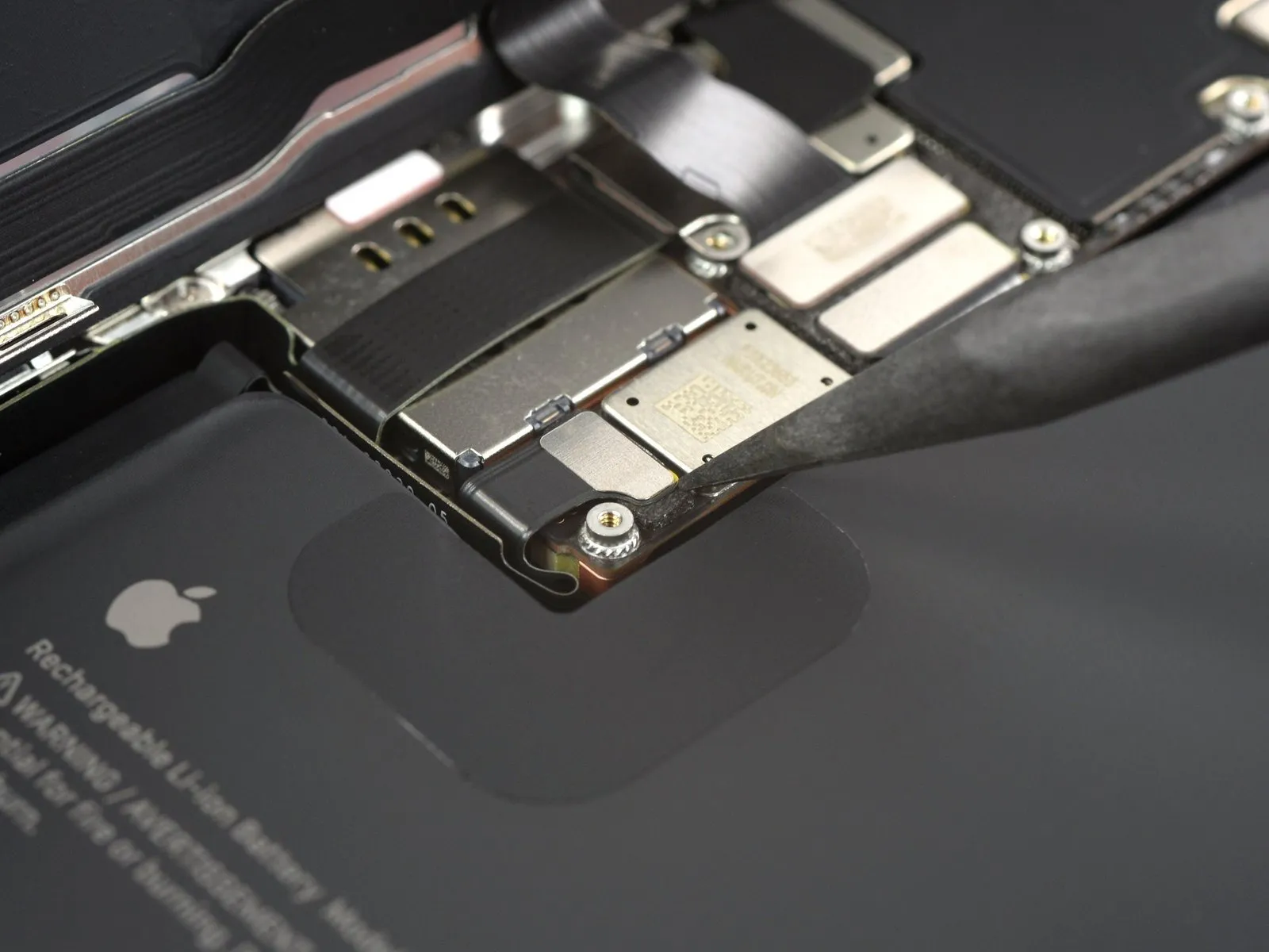
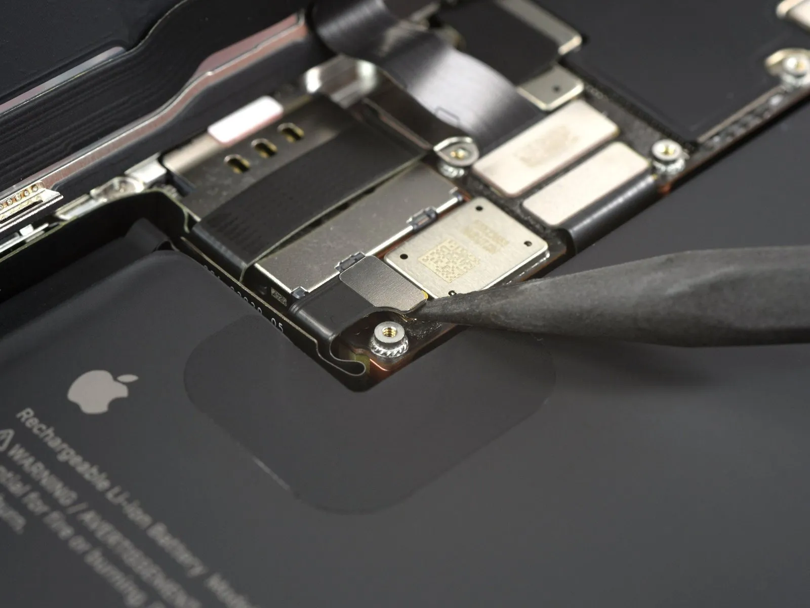
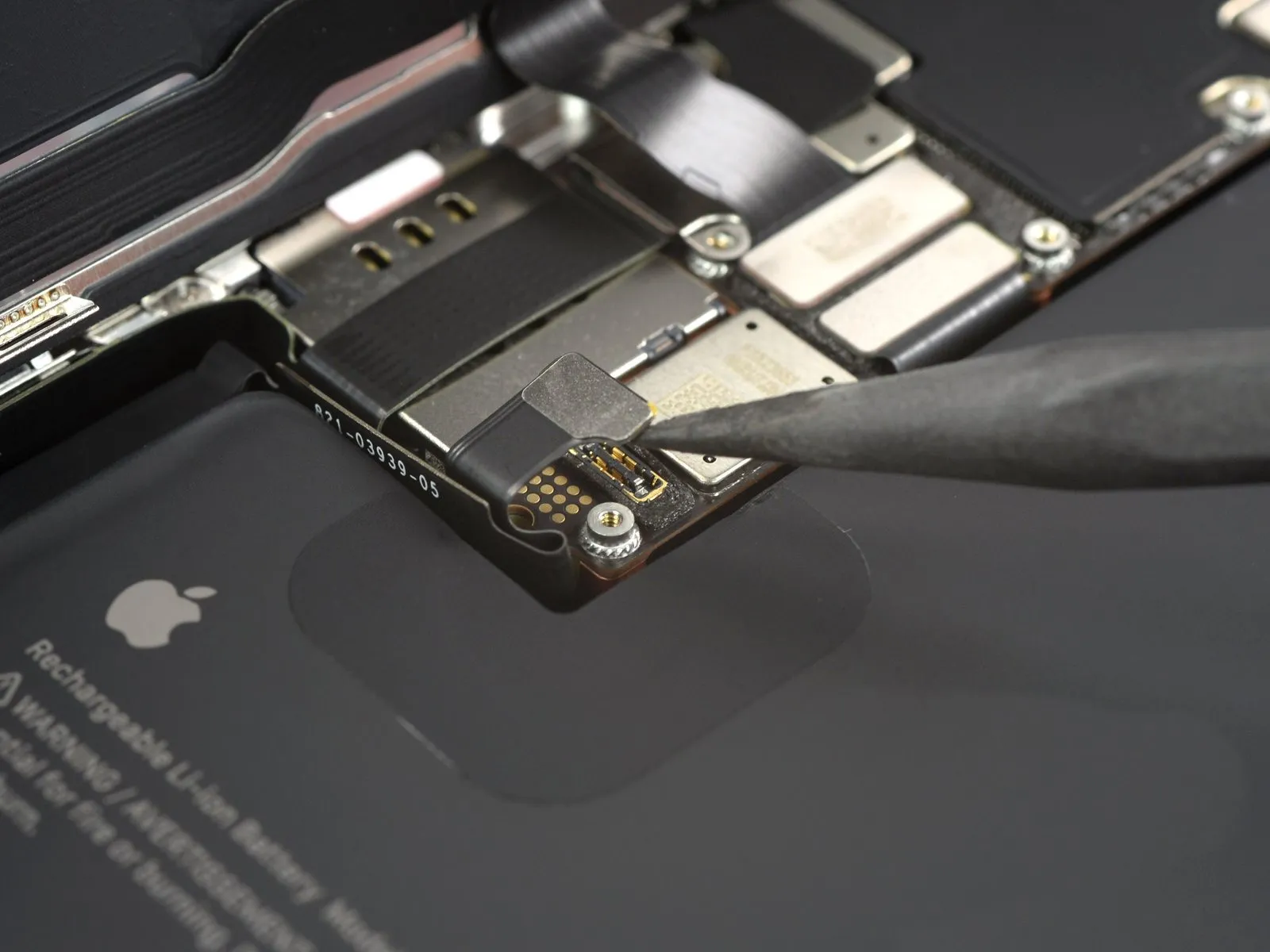
- The connector should be disengaged by applying upward pressure, ensuring a vertical trajectory relative to its receptacle.
- Exercise caution to avoid compromising the integrity of the black silicone sealant that encases this and other board interfaces, as it safeguards against ingress of water and particulate matter.
- To preclude unintended electrical connection and potential power delivery to the device during the repair process, slightly deflect the connector away from the logic board's surface.
Step 19 | Disconnect the display cable
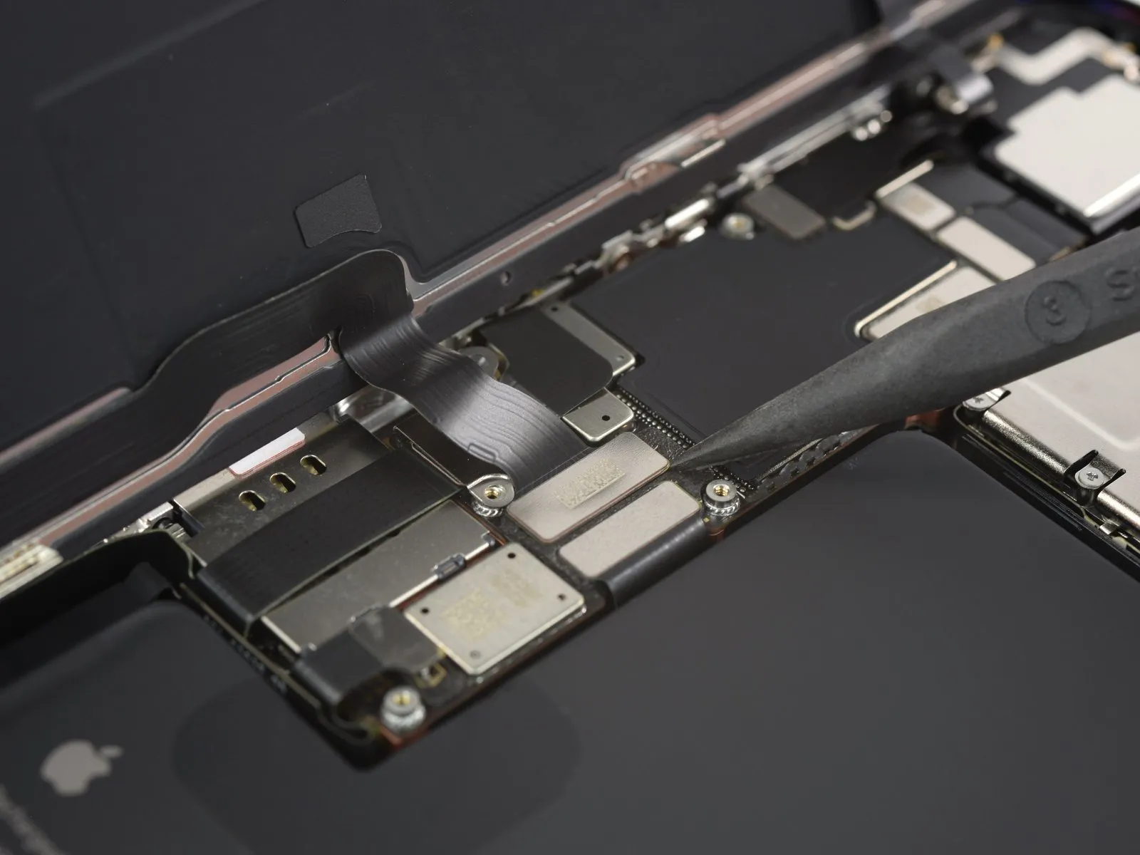
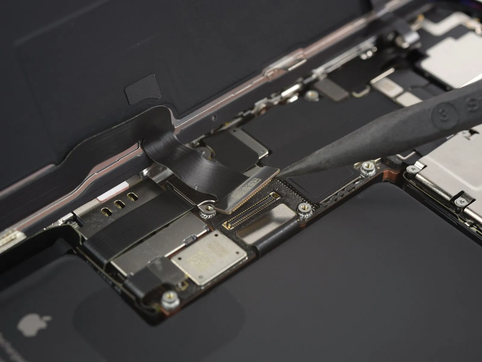
- Re-establishment of the connection involves a precise procedure: ensure proper alignment and apply downward pressure to each side of the connector sequentially until an audible click confirms secure engagement, avoiding central pressure.
- Misalignment during re-attachment poses a risk of pin deformation, which could result in irreversible component failure; therefore, meticulous alignment is crucial.
Step 20
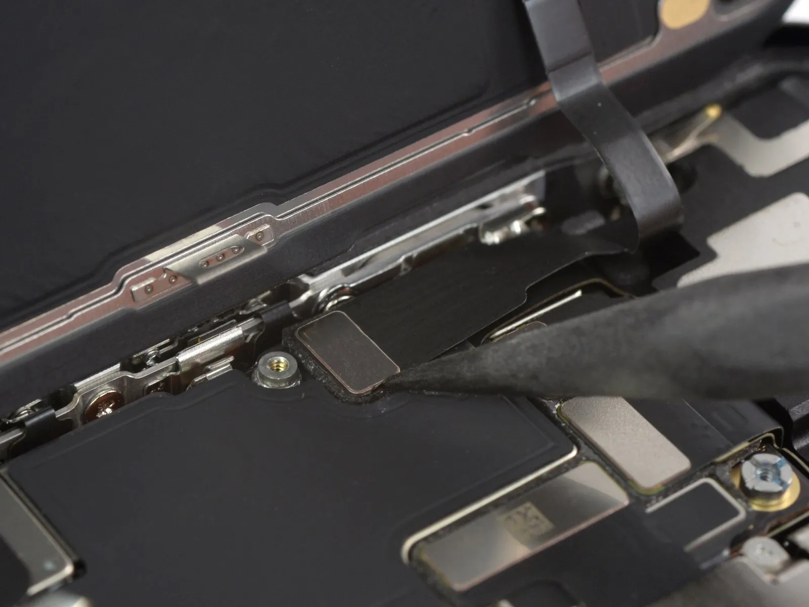
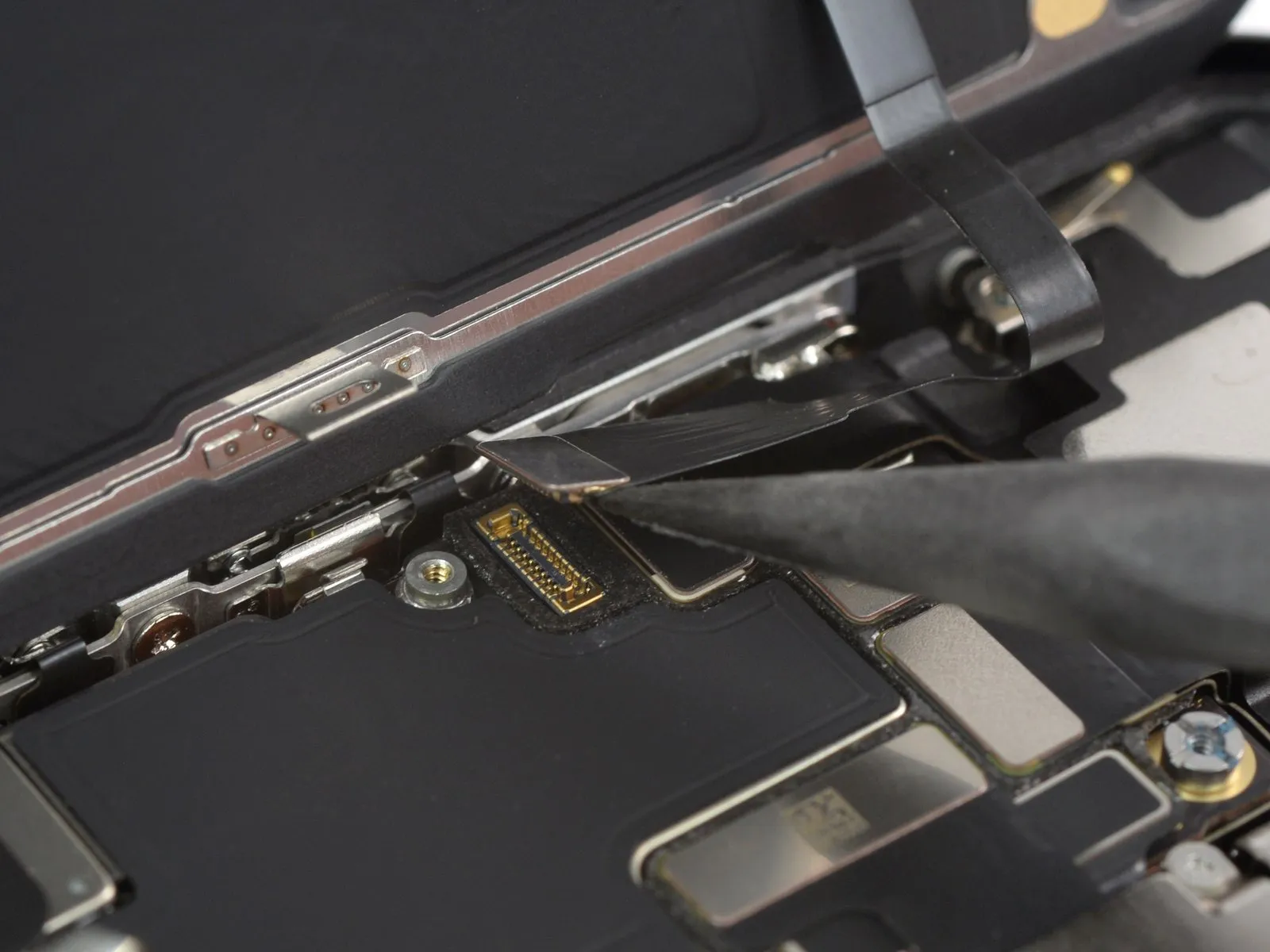
- The connector must be separated from its socket via a straight upward prying motion, utilizing the pointed end of a spudger.
Step 21 | Remove the screen
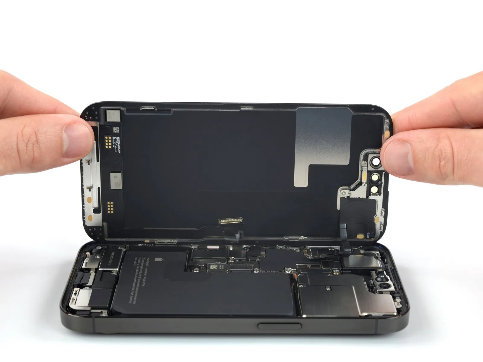
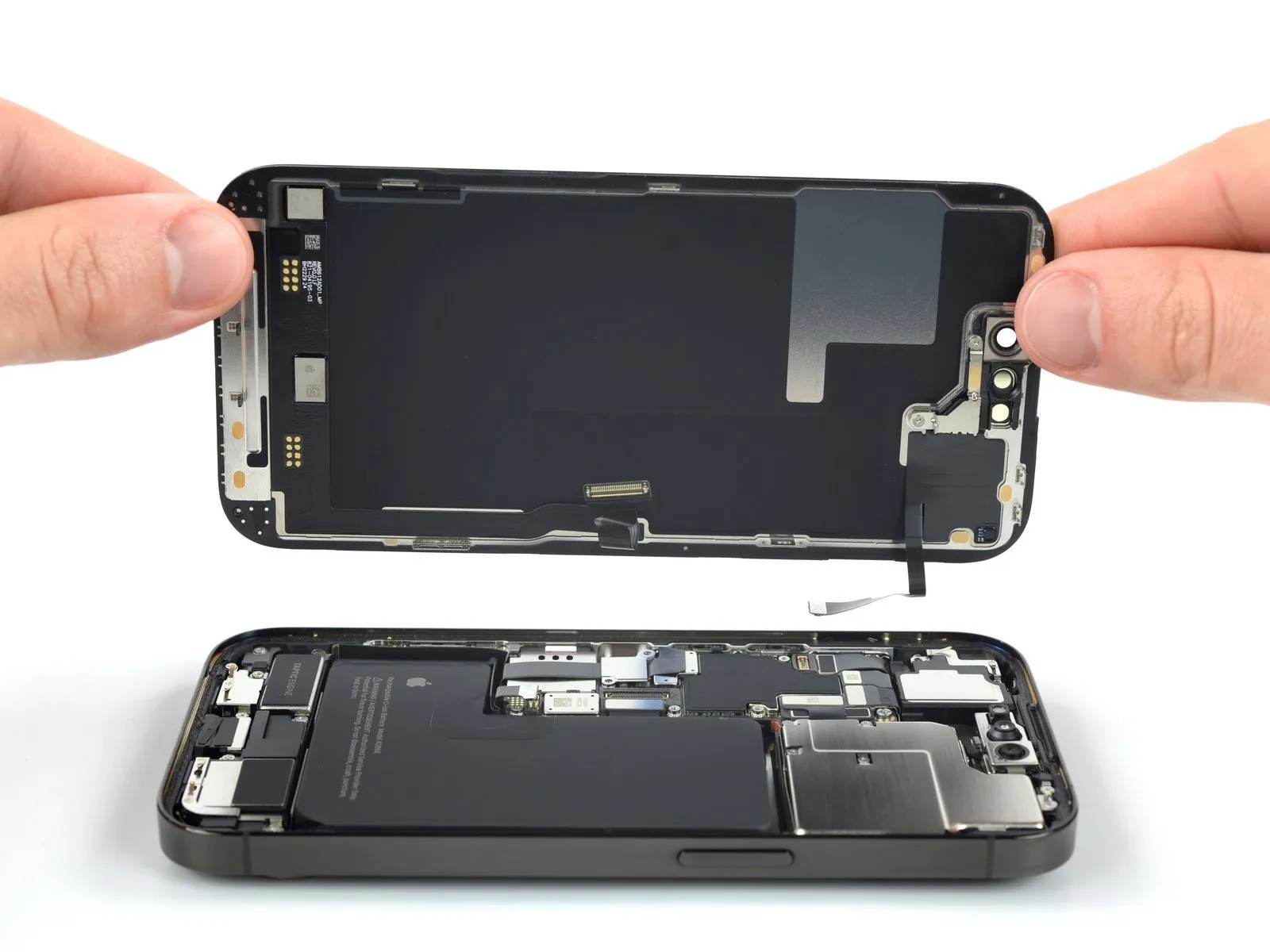
- Detach the display panel from the device’s housing.
- Following a thorough cleaning of the contact surfaces utilizing isopropyl alcohol exceeding 90% purity, apply fresh adhesive material to ensure proper reattachment.
- A temporary halt in the reassembly process is permissible at this stage to facilitate the substitution of the screen’s adhesive strips, if desired.
Step 22 | Unfasten the earpiece speaker screws

Step 23 | Pry up the earpiece speaker


- Utilize the tapered end of a spudger to gain access beneath the right-hand perimeter of the earpiece speaker assembly.
- Apply upward force with the spudger to disengage the earpiece speaker and release its adhesive bond.
- A rubber gasket is affixed to the upper right corner of the earpiece speaker; ensure proper alignment with its corresponding cavity within the device frame during reinstallation.
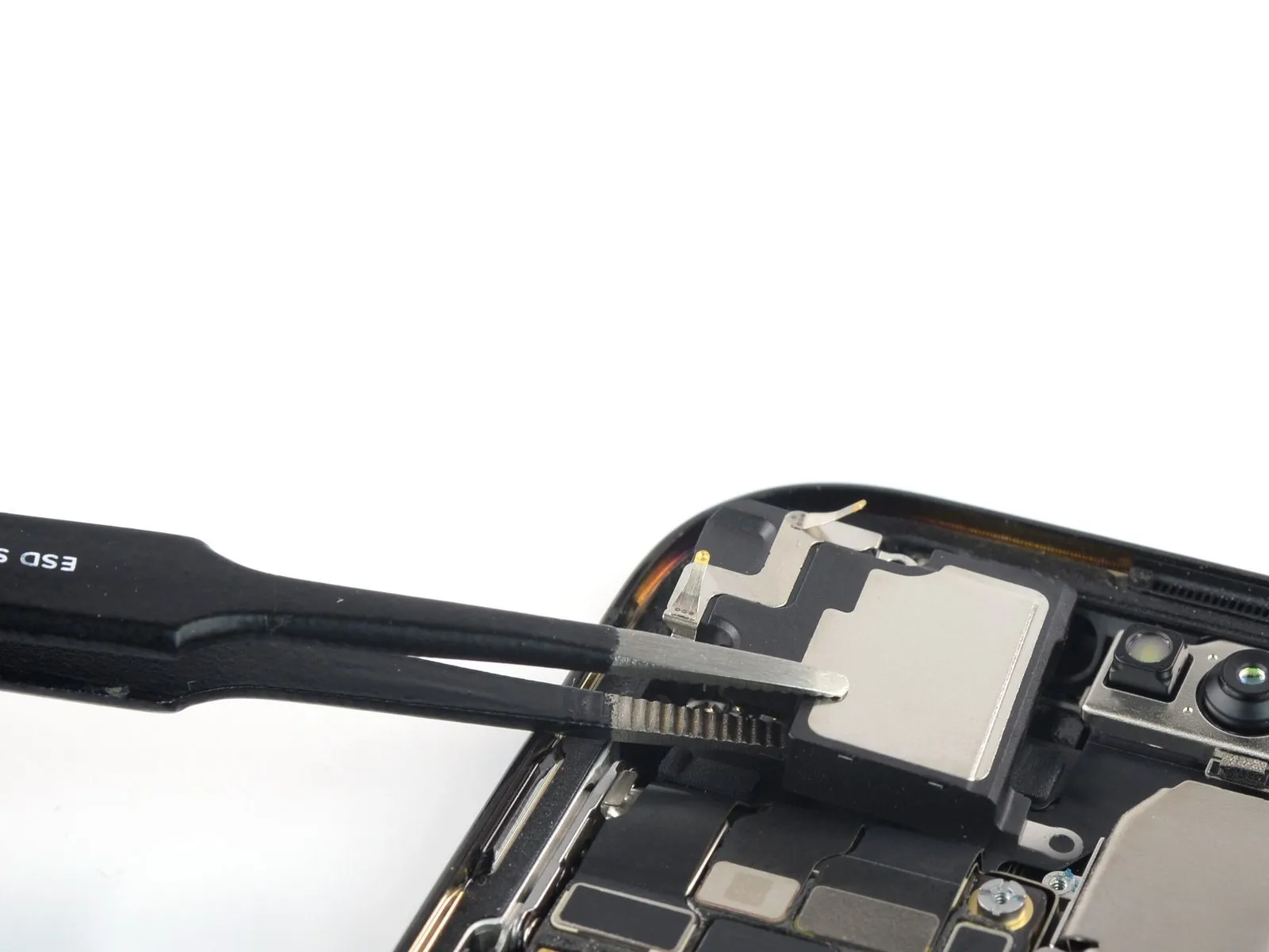
Step 24 | Remove the earpiece speaker

Step 25 | Disconnect the camera and sensor cables


- Employ a spudger to release the camera and sensor cable connections, lifting the connectors vertically from their receptacles.The camera and sensor cables' connectors must be disengaged using a spudger by applying upward force to detach them from their respective sockets.To separate the camera and sensor cables, utilize a spudger and apply direct upward pressure to the connectors as you disengage them from their sockets.
Step 26 | Remove the front-facing camera assembly


- Employ tweezers or your fingertips to detach the front-facing camera module.