iPhone 14 Pro Lidar Sensor Replacement
This document provides instructions for the removal and replacement of the lidar sensor within an iPhone 14 Pro.
The creation of this guide utilized the A2890 model, which is the international variant; while procedures remain consistent across all iPhone 14 Pro models, minor visual differences might be observed.
- Essential materials for this repair include replacement adhesive.The screen must be properly secured during reassembly with the application of fresh adhesive to ensure stability.The device's ability to maintain its original water resistance level is contingent upon the quality of the new screen adhesive application.
- Following this repair, the iPhone will no longer be covered by the manufacturer's official Ingress Protection (IP) rating.
Step 1 | Remove the pentalobe screws
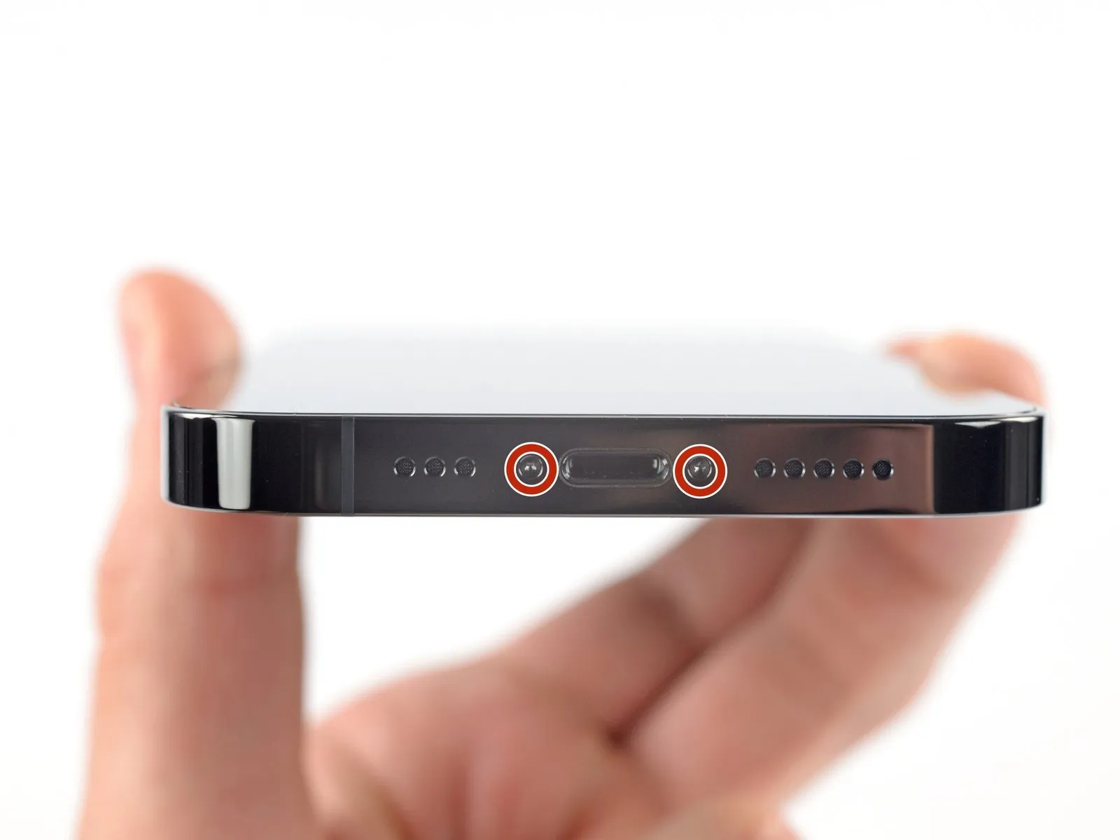
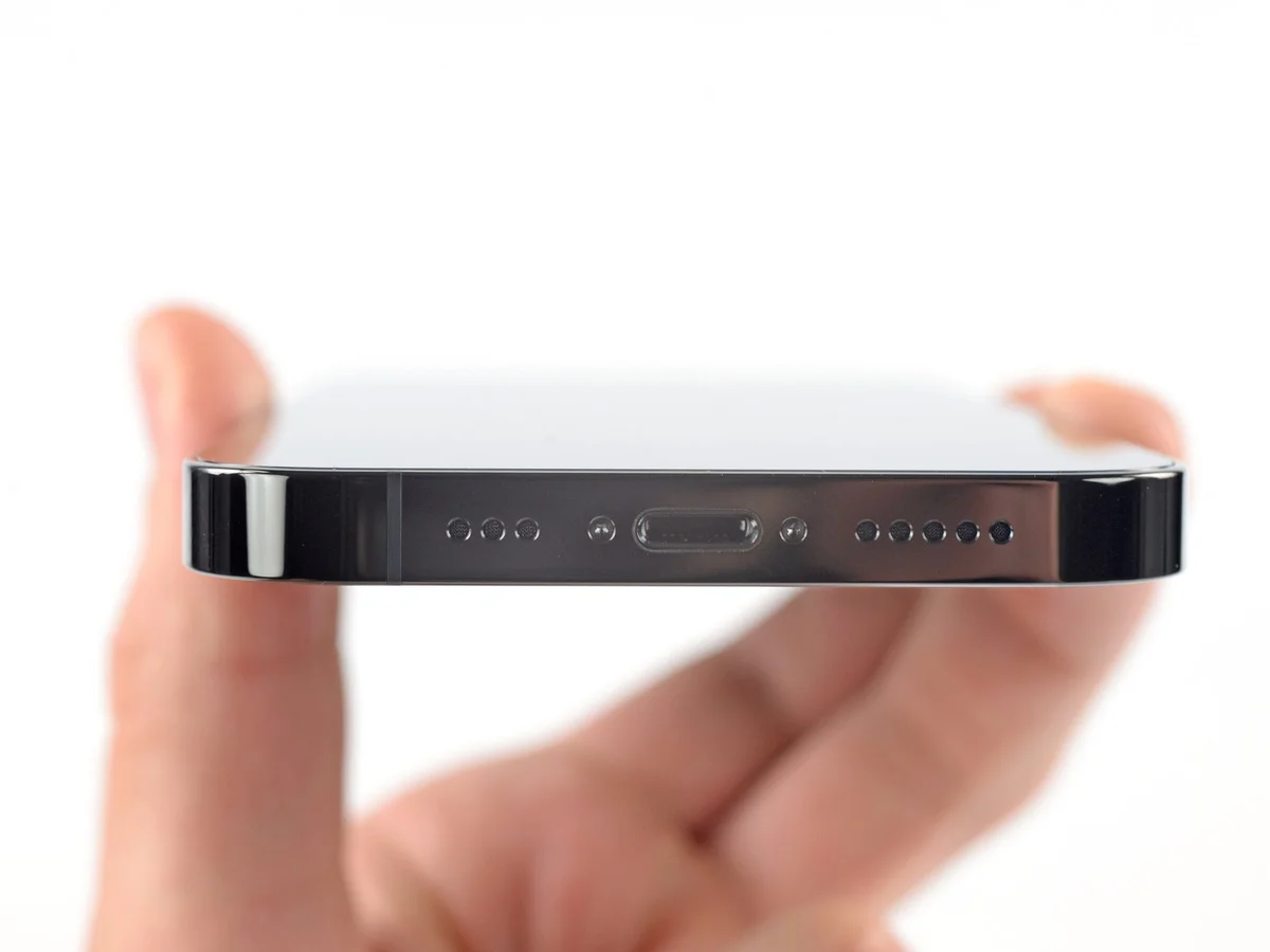
- Prior to commencing the disassembly process, ensure the iPhone is completely de-energized.
- The process requires the extraction of two screws.These screws are of a pentalobe P2 type, measuring precisely 6.8 millimeters in length.These fasteners are situated along the lower perimeter of the iPhone's casing.
Step 2 | Mark your opening picks


- Excessive insertion of a pick can potentially harm the device; therefore, it's crucial to implement a method for limiting its depth.
Using a precise measuring tool, determine a distance of3 millimetersfrom the pick's distal end and clearly indicate this point with a durable, permanent marker. - For enhanced precision, consider marking additional corners of the pick with varying measurement distances.
- As another option, securely affix a coin to the pick's tip, positioning it precisely 3 millimeters away from the end.
Step 3 | Tape over any cracks


- To mitigate additional damage and potential injury while repairing a fractured iPhone display, secure the broken glass with adhesive tape.
Apply successive layers of transparent packing tape across the iPhone's screen surface, ensuring complete coverage of the display's front. - Protect your vision by utilizing safety eyewear to guard against any dislodged glass fragments that may occur during the repair process.
- Should the suction cup fail to adhere properly in subsequent steps, construct a handle from a robust tape, like duct tape, to elevate the screen.
- As a last resort, apply a small amount of superglue to affix the suction cup directly to the iPhone's screen.
Step 4 | Anti-Clamp instructions


The following three actions illustrate the operation of the Anti-Clamp, a specialized tool developed to simplify the initial separation process; if this tool is unavailable, proceed to the subsequent three steps for an alternative approach.
Detailed instructions regarding the Anti-Clamp's usage are available in a separate, comprehensive guide.
- Grasp the blue handle and move it in a rearward direction to disengage the Anti-Clamp's securing arms.
- Position the arms across either the left or right side of your iPhone's frame.
- Place the suction cups close to the lower edge of the iPhone, ensuring one is located on the front surface and the other on the rear.
- Apply pressure by compressing the suction cups together to establish a secure adhesion to the intended location.
- Should the iPhone's surface prove excessively smooth, preventing adequate Anti-Clamp adhesion, applying adhesive tape can enhance grip.
Step 5


- Advance the blue handle to secure the clamping arms in a locked position.
- Rotate the handle a full 360 degrees, or continue until the suction cups begin to deform.
- Maintain the parallel alignment of the suction cups; should misalignment occur, slightly release the suction cups and reposition the arms.
Step 6


- Employ a hair dryer to apply warmth to the iPhone's lower edge; the surface temperature should reach a level just uncomfortable to touch.
- Refer to a dedicated guide for detailed instructions regarding the proper operation of a hair dryer.
- Allow a sixty-second interval to permit the adhesive to loosen and create a discernible separation.
- Once a noticeable gap forms, carefully introduce an opening pick beneath the screen's plastic frame.
- Should the Anti-Clamp tool fail to generate a sufficient separation, increase the heat and rotate the handle incrementally by ninety degrees.
- Avoid excessive rotation, restricting adjustments to ninety-degree increments, and observe a one-minute pause between rotations, allowing the tool and time to effectively separate the components.
- Proceed to bypass the subsequent two steps in this repair sequence.
Step 7 | Heat the bottom edge

- Apply warmth to the iPhone's lower border utilizing a hairdryer or heat gun, continuing until the surface temperature becomes marginally uncomfortable to the touch.
- Avoid prolonged, localized heat application with the heat gun to prevent component damage.
Step 8 | Insert an opening pick
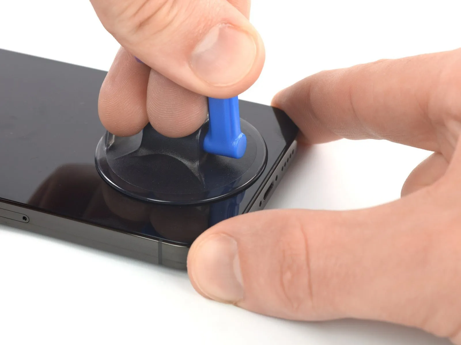
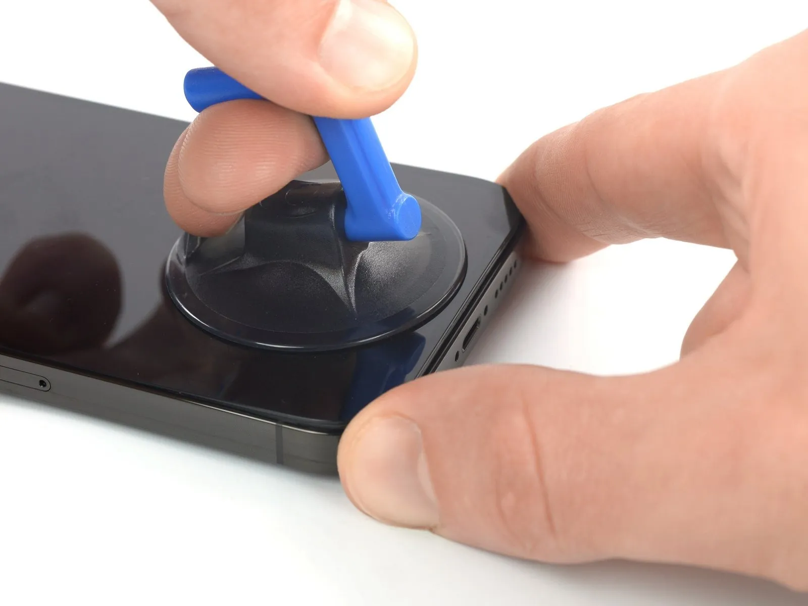
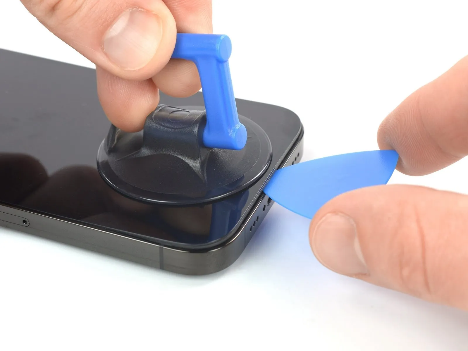
- Maintain consistent, substantial upward force on the suction cup to generate a minimal separation between the display and the device's chassis.
- Introduce an opening tool into the space formed beneath the screen's surrounding plastic trim.
- Because the screen is secured with a robust, waterproof sealant, considerable force may be required to initially separate the display; if separation proves difficult, apply additional heat and gently oscillate the display to reduce adhesive strength until a sufficient gap is achieved for tool insertion.
Step 9 | Heat the right edge


Step 10 | Separate the right adhesive

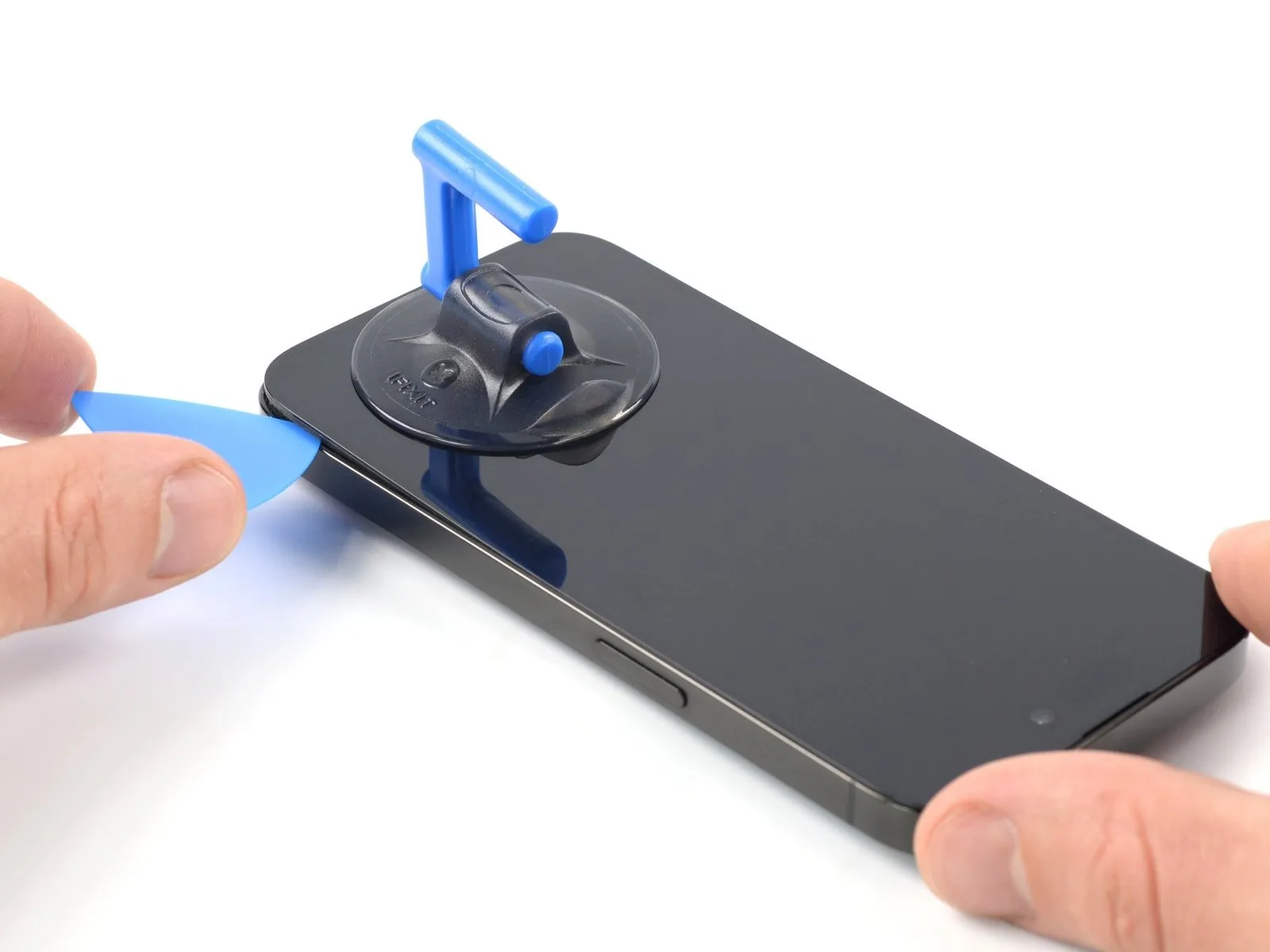
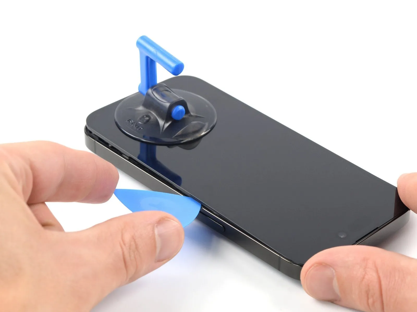
- Utilize a specialized opening pick to release the adhesive securing the iPhone's lower-right perimeter.
- Progressively move the pick upwards along the right side of the iPhone's casing, advancing toward the upper-right corner.
- Ensure the pick's insertion depth remains below a maximum of 3 millimeters to prevent potential harm to delicate internal parts.Maintaining the pick's position at the top-right corner is necessary before proceeding with subsequent steps.The adhesive bond is broken by carefully maneuvering the opening pick along the iPhone's edge.
- To avoid internal component damage, restrict the pick's penetration to a depth of no more than 3 mm.
Step 11 | Heat the top edge

Step 12 | Separate the top adhesive

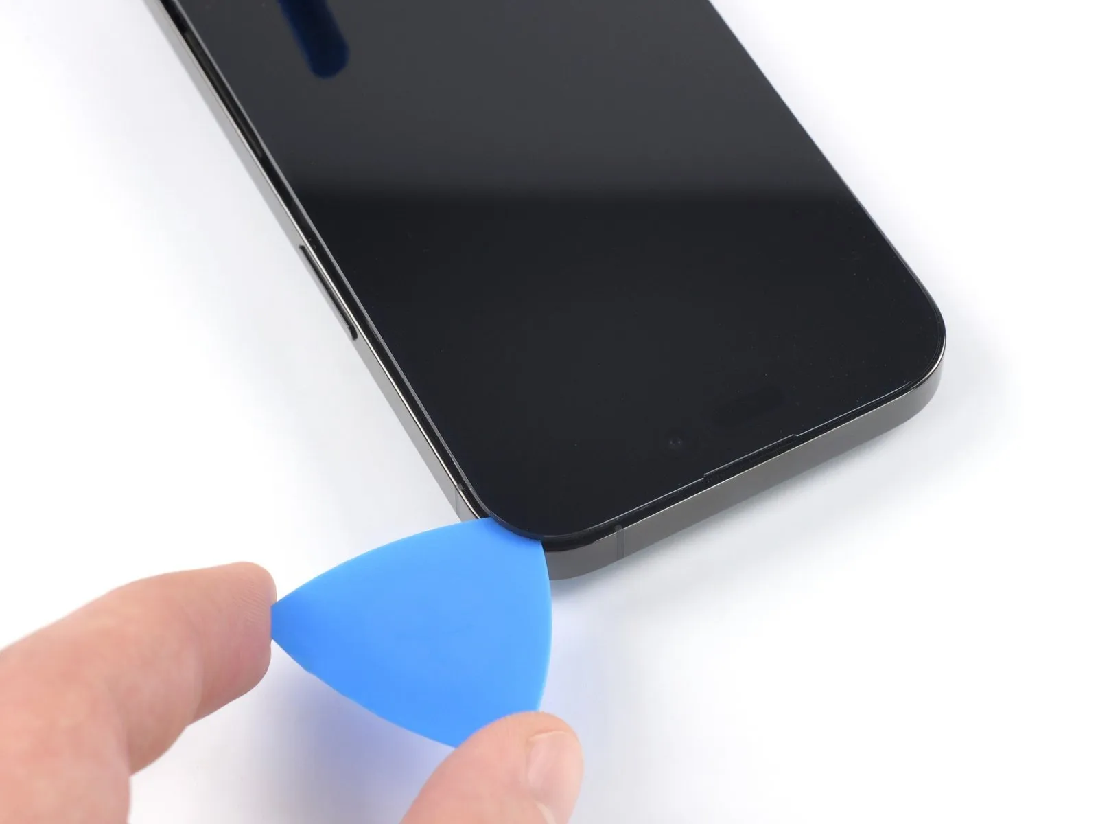
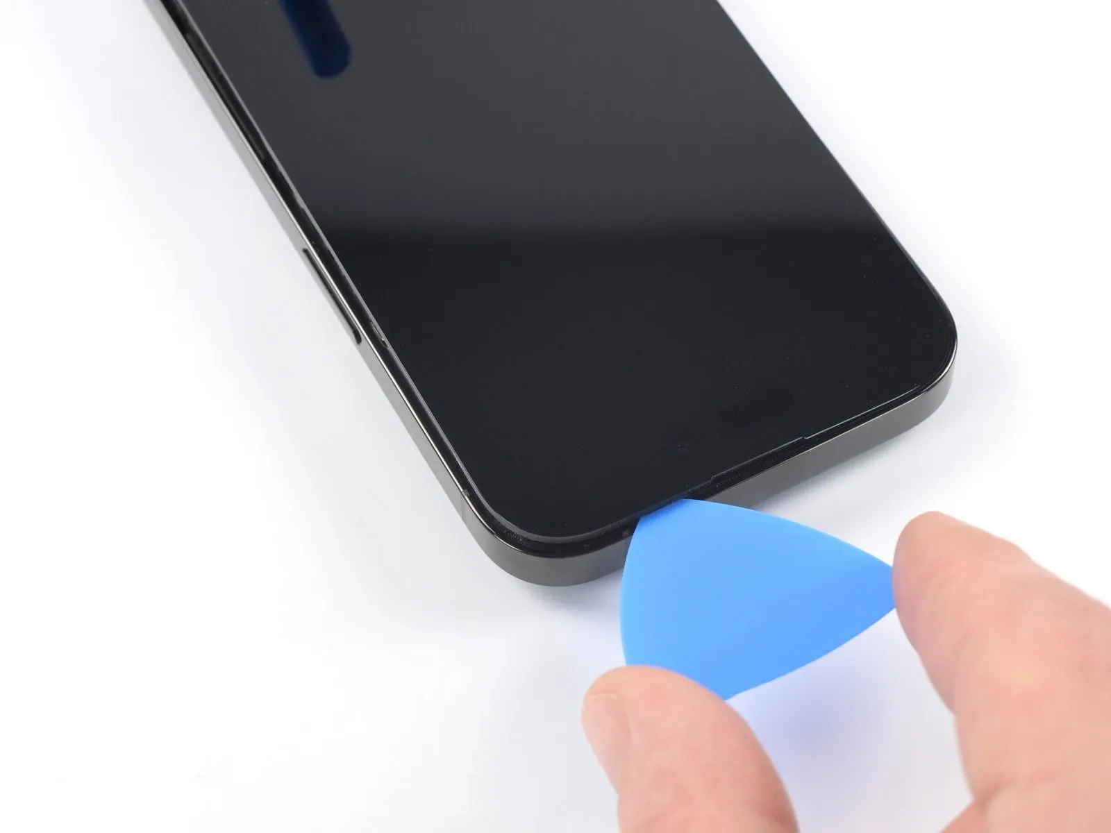
- Utilize a specialized opening tool to carefully disengage the adhesive securing the iPhone's top right edge.
- To prevent potential harm to the proximity and other sensors located at the top of the device, ensure the opening tool's insertion depth remains below 3 millimeters.Maintaining the pick's position within the top left corner is necessary to facilitate subsequent repair steps.The adhesive bond between the display assembly and the chassis must be broken with precision around the perimeter.
- Carefully maneuvering the opening tool allows for controlled separation of the display without compromising delicate components.
Step 13 | Heat the left edge


Step 14 | Separate the left adhesive


- Fragile wiring is situated along the left side of the iPhone’s frame; exercise caution.Insertion of the opening tool should not exceed a depth of 2 millimeters to prevent cable damage.Perform a rotational movement of the tool focused on the upper-left screen corner.
- Advance the tool along the left edge to release the adhesive bond.
- Should adhesive separation prove difficult, apply localized heat to the left edge to soften the adhesive.
- The adhesive securing the display assembly requires careful separation to avoid internal component compromise.
Step 15 | Open the iPhone
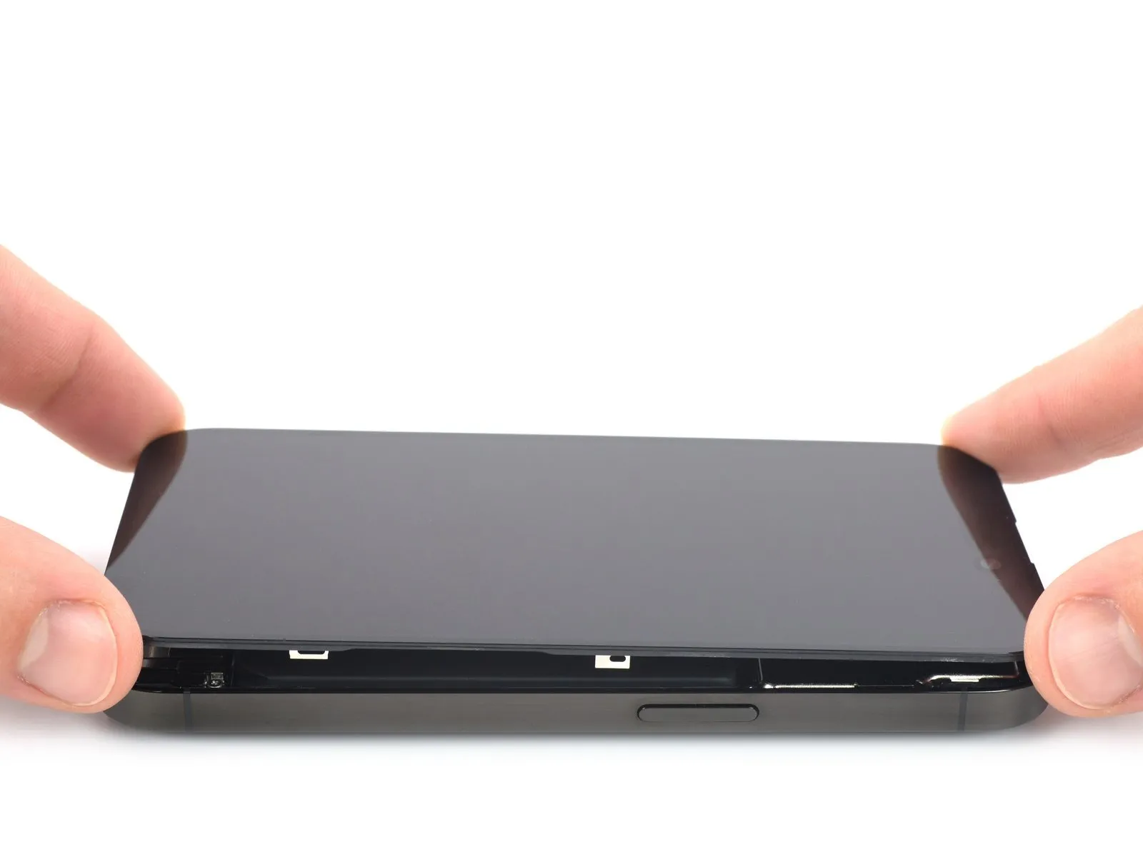
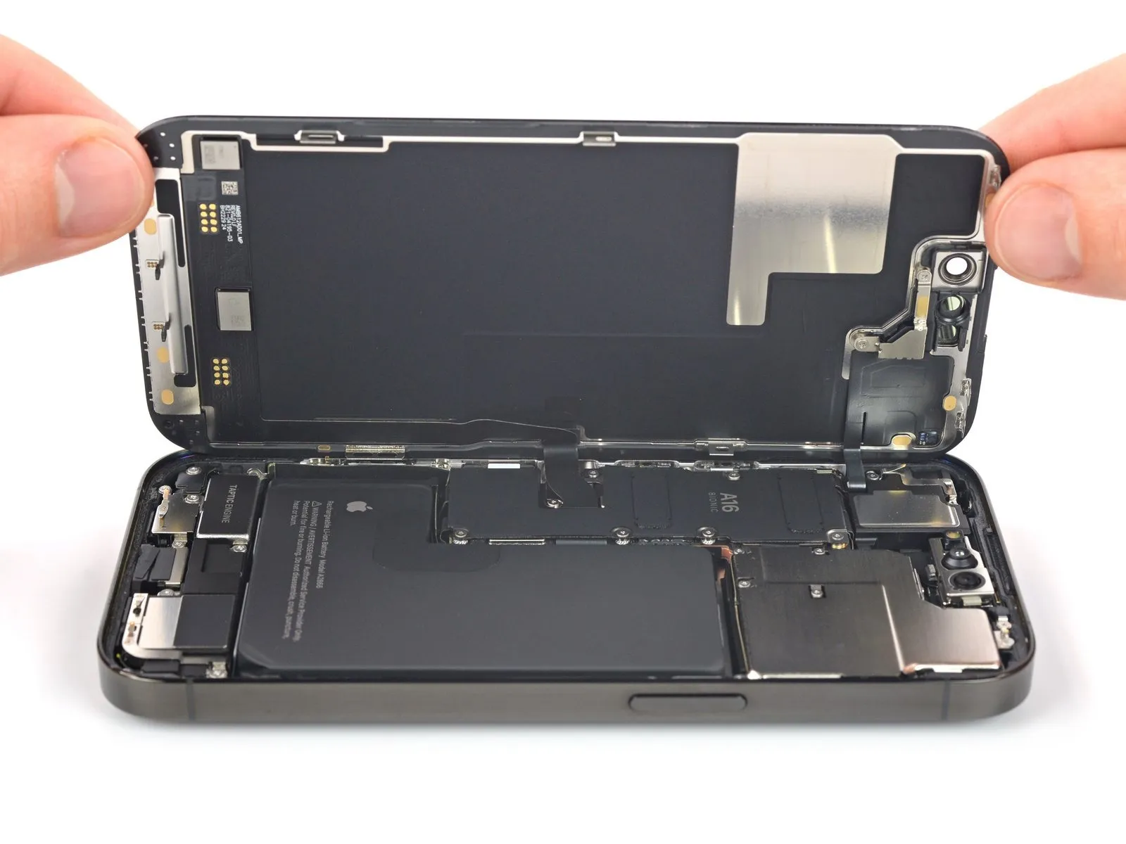
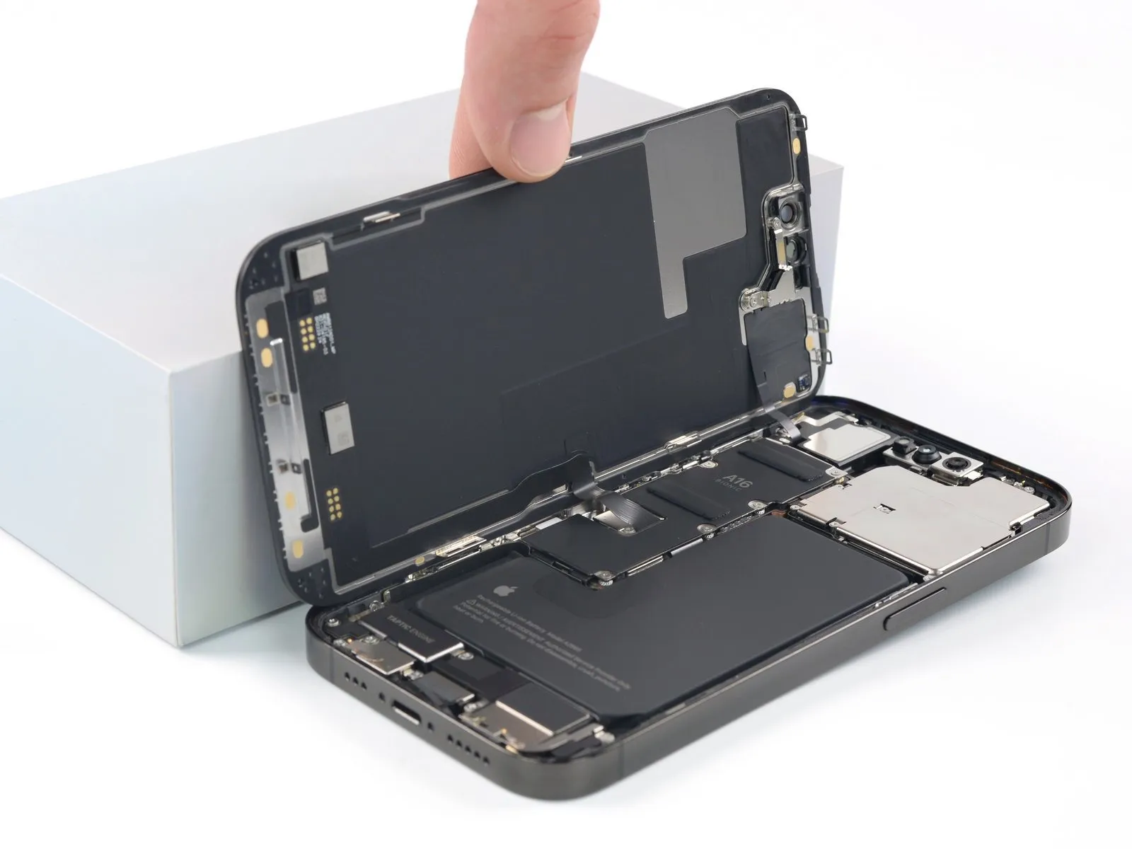
- Detach the suction handle from the display assembly.
- Reorient the iPhone, positioning its right edge towards your perspective.
- Initiate the iPhone's opening procedure by pivoting the display upwards from the right side, mimicking the action of opening a book's cover.
- Secure the display in an upright position using a support to maintain access to the internal components during the repair process.
- Alternatively, the suction handle can be utilized to prop the display if a separate support is unavailable.
Step 16 | Unfasten the battery connector cover screws
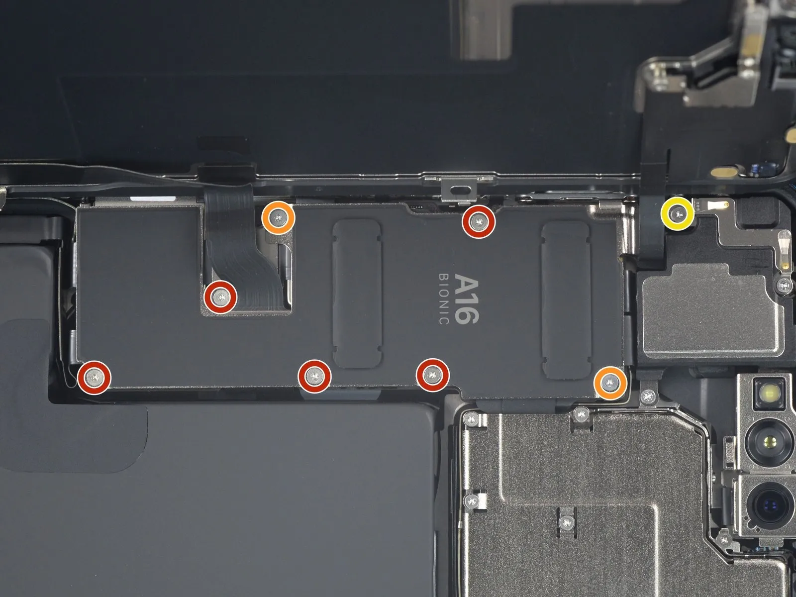
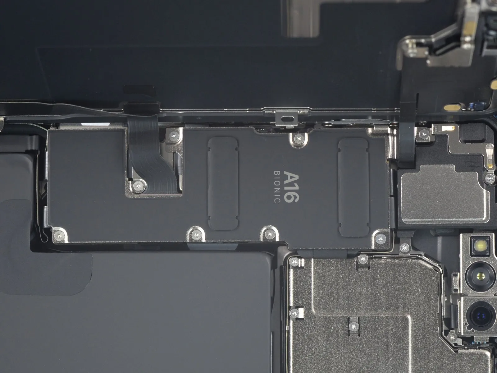
- Specifically, five screws, each measuring 1.3 millimeters in length, will be removed.
Additionally, two screws with a length of 1.6 millimeters must be unscrewed.A single screw, extending 1.9 millimeters, also requires removal.Carefully monitor the location of each screw throughout the repair process.
Ensure that every screw is reinstalled in its original position to prevent potential damage to the iPhone.Prior to permanently reattaching the screen, verify full operational status by powering on the device.A comprehensive functional test of the iPhone is essential during reassembly.
Completely shut down the iPhone before proceeding with the final screen sealing step.Maintaining meticulous organization of the screws is crucial for a successful repair.The battery connector cover is secured by a combination of screw sizes. - Proper screw placement is vital for the device's continued functionality.
- A Y000 screwdriver is the specifically required tool for this task.
Step 17 | Remove the battery connector cover
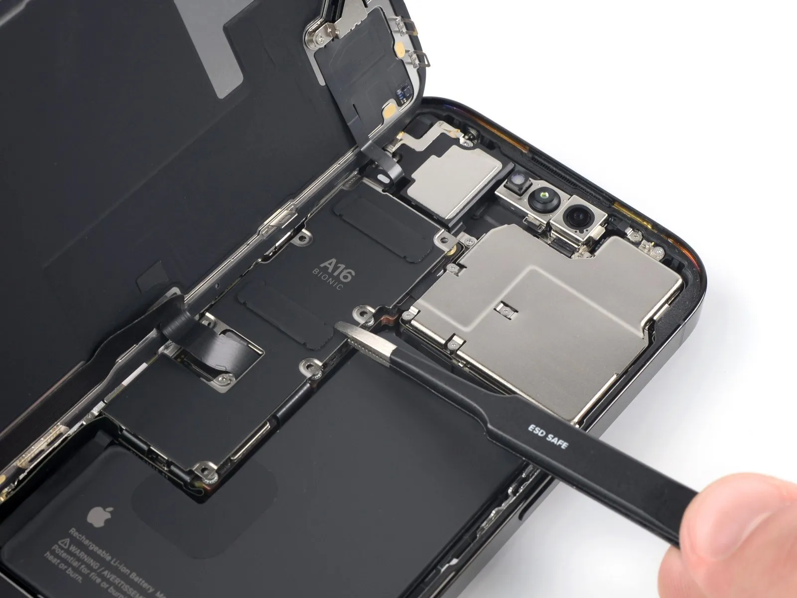
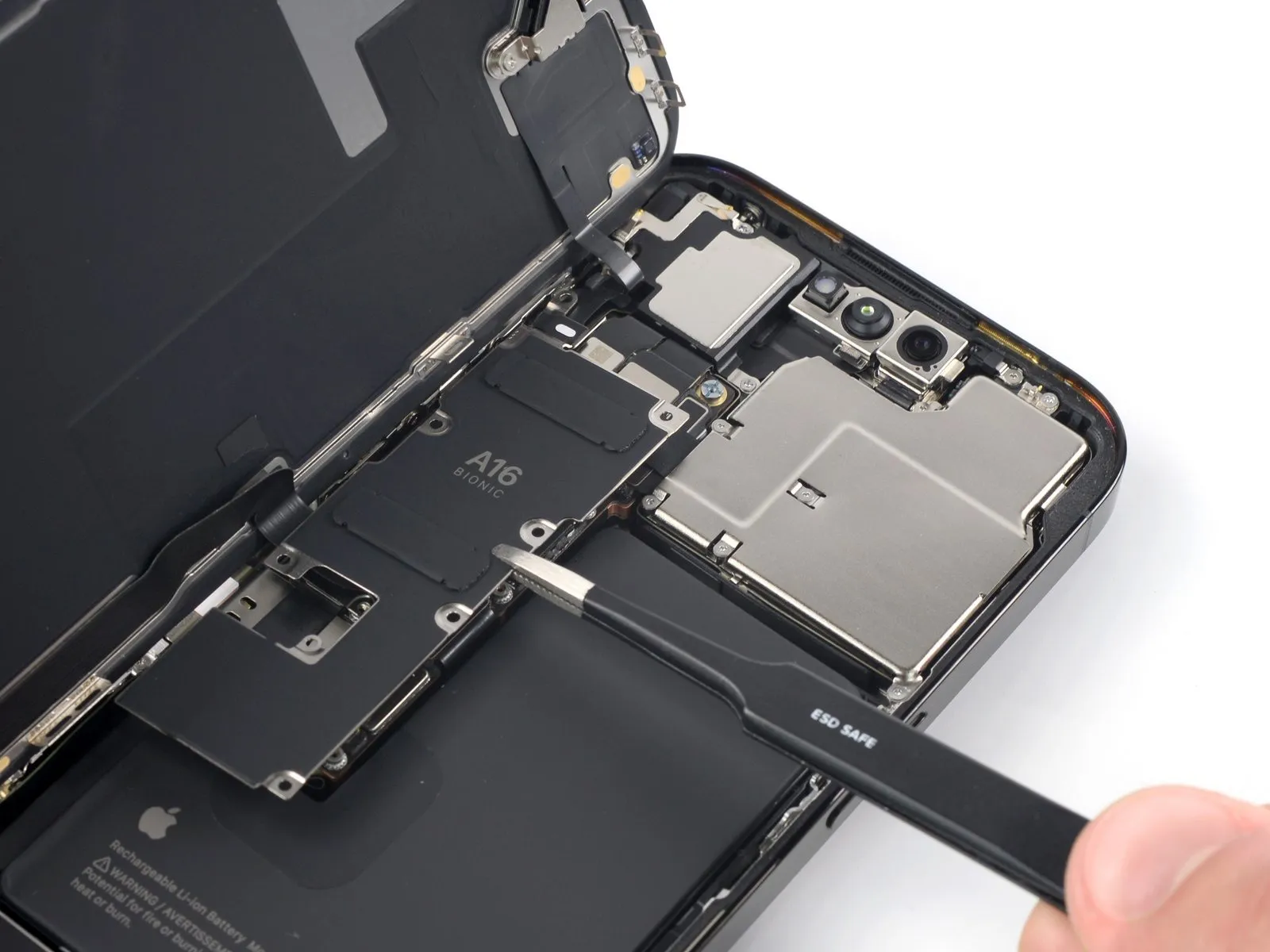
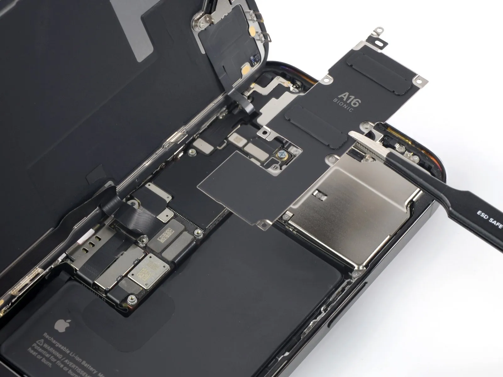
- To permit access to the flexible cables, carefully advance the connector cover in a downward motion.
- Detach the connector cover from its position.
Step 18 | Disconnect the battery
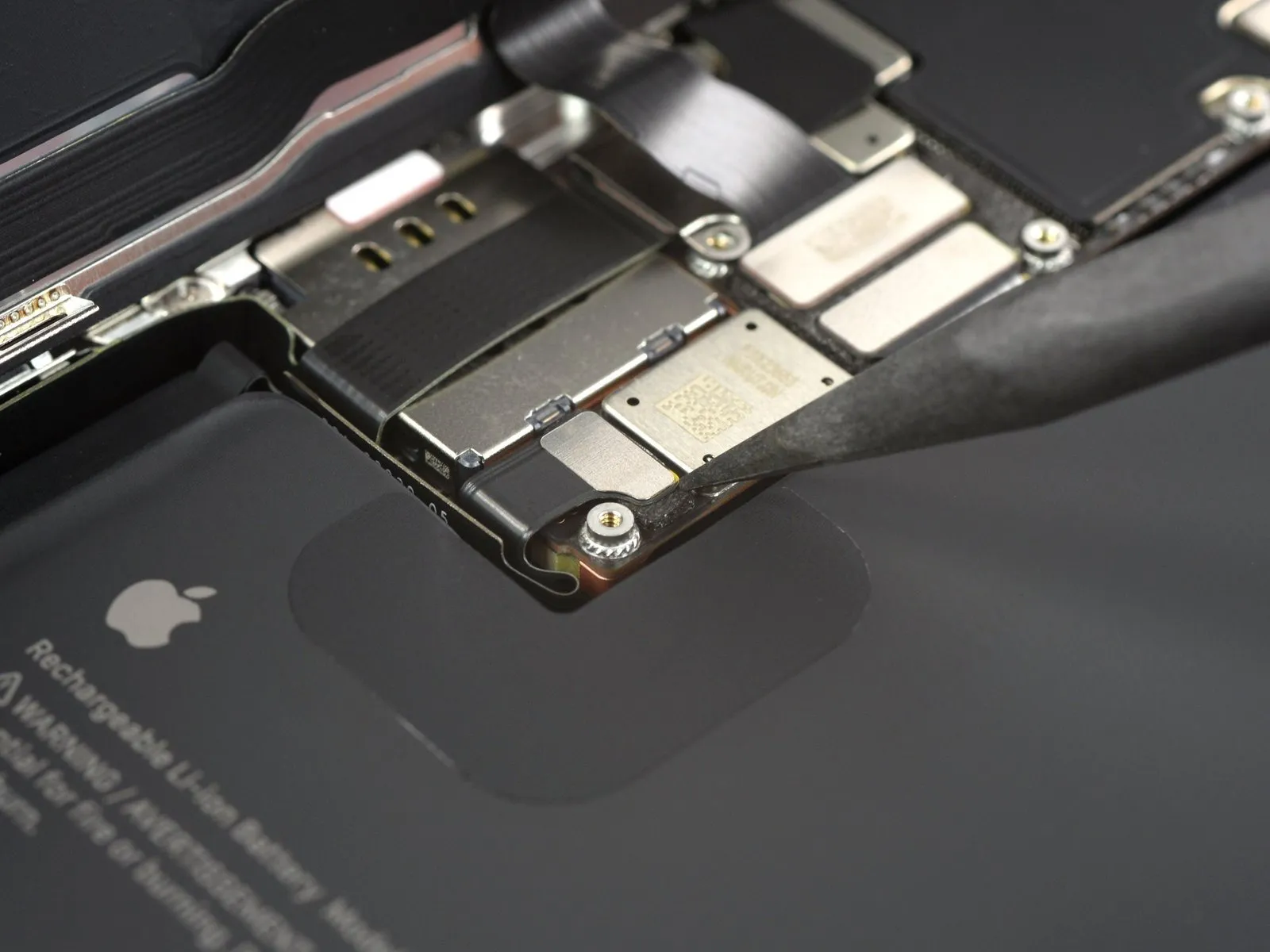
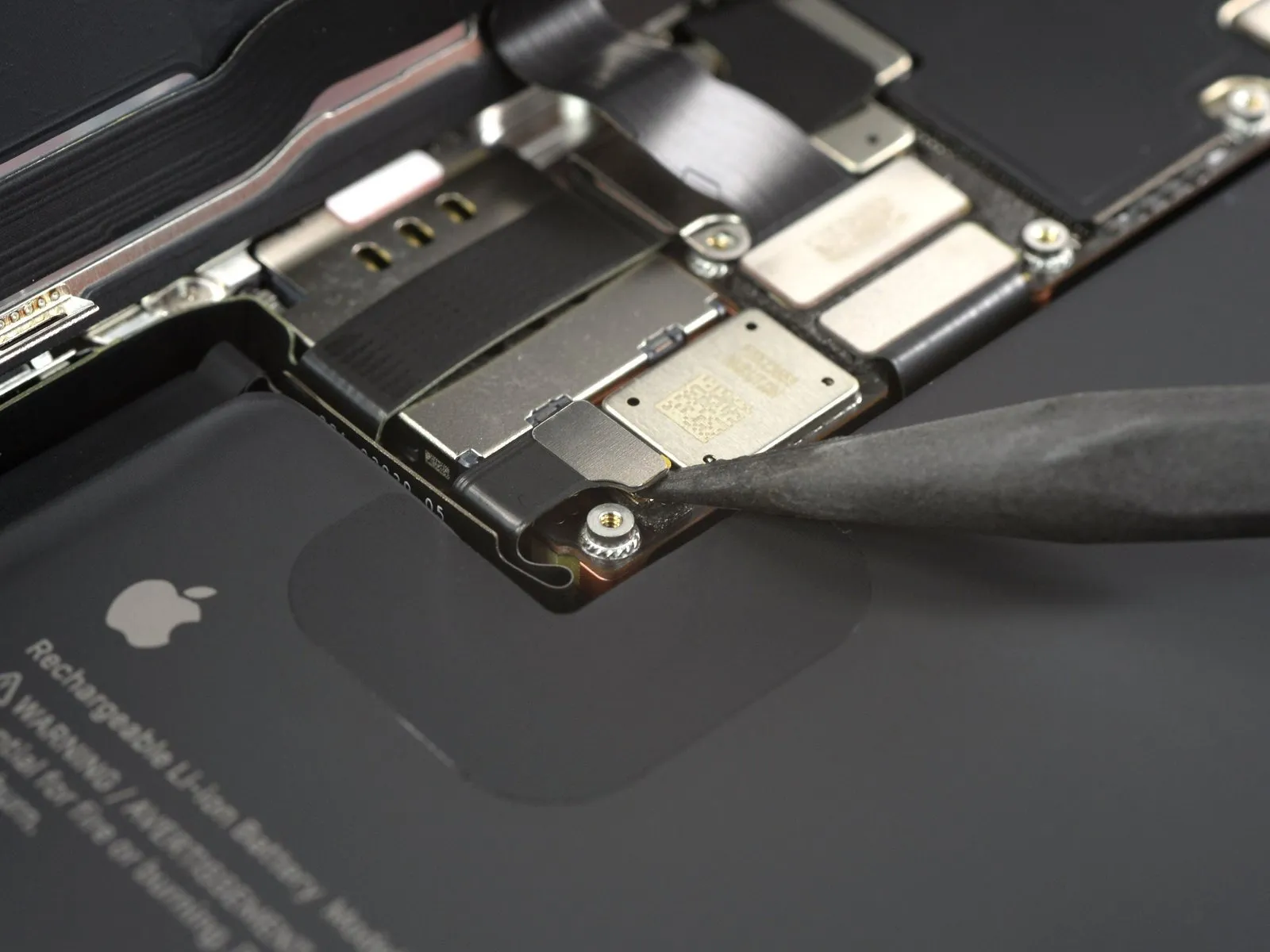
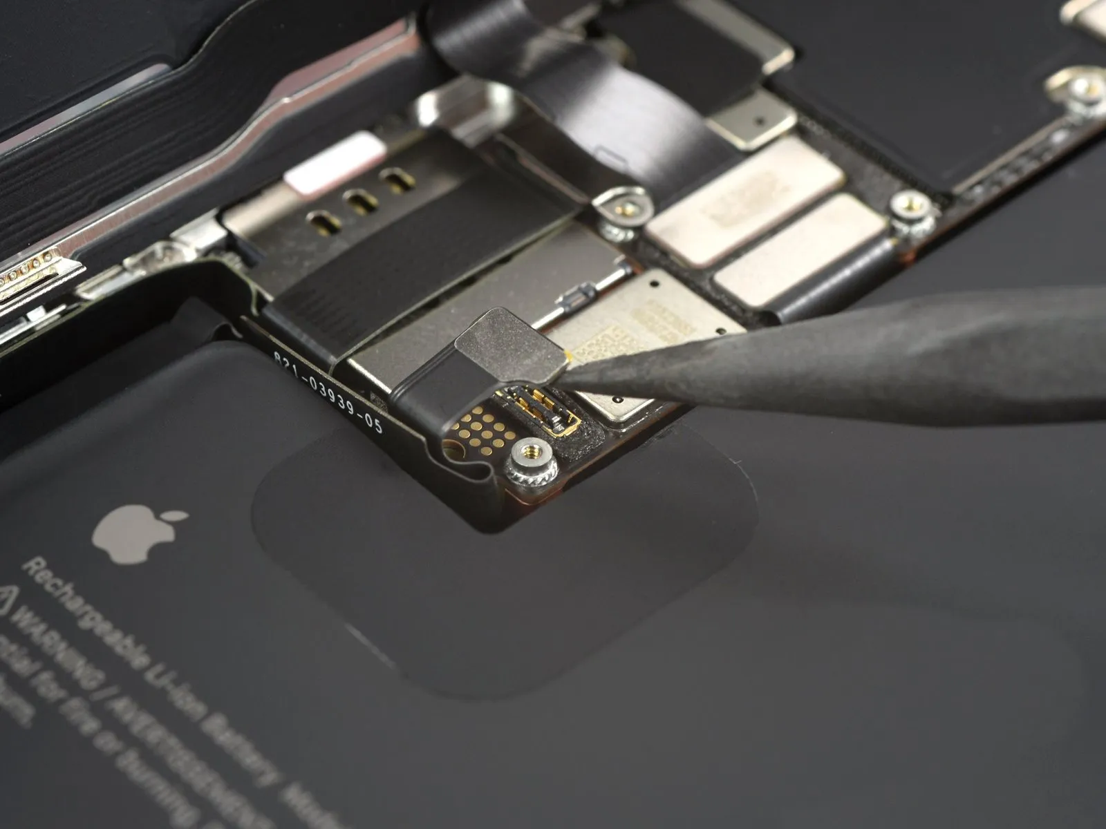
- The battery connector must be detached by applying upward force directly above it, utilizing the spudger's tip.
- Exercise caution to prevent harm to the black silicone seals that encircle this and other connectors on the circuit board, as they offer crucial defense against water and particulate contamination.
- To inhibit unintended reconnection, gently deflect the connector away from the logic board's surface.
Step 19 | Disconnect the display cable
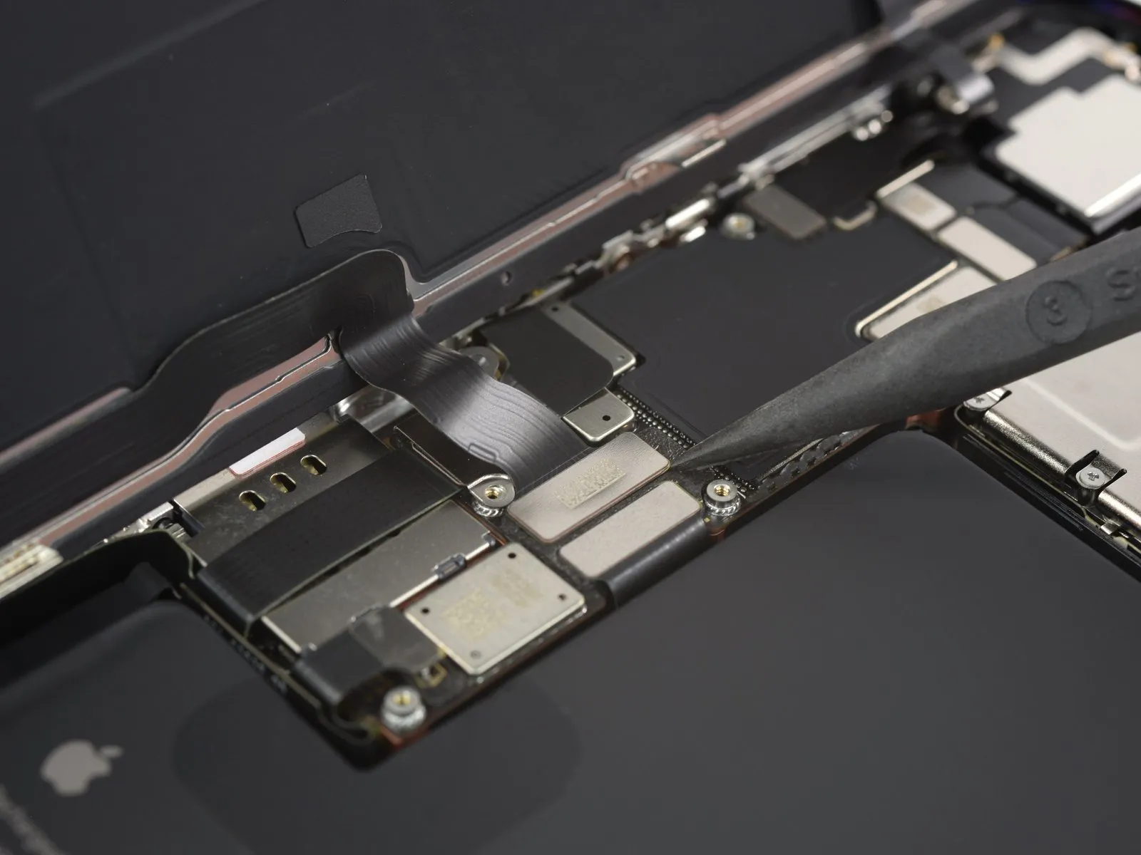
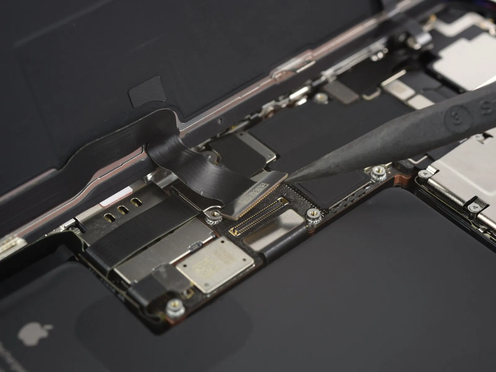
- Re-establishment of the connection requires meticulous alignment; apply pressure to one lateral edge of the connector until a distinct audible click confirms secure engagement, then replicate this process on the opposing side.
- Avoid applying pressure to the central portion of the connector during re-attachment, as misalignment can result in pin deformation, potentially leading to irreversible component failure.
Step 20
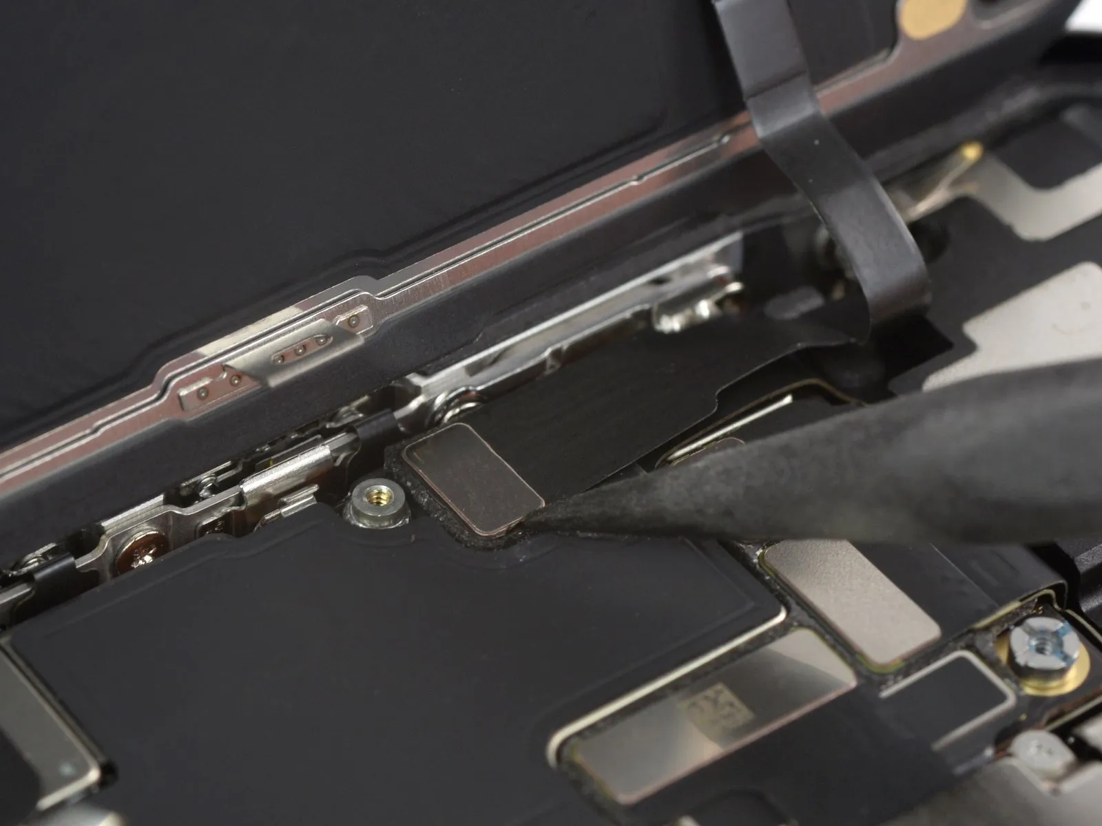
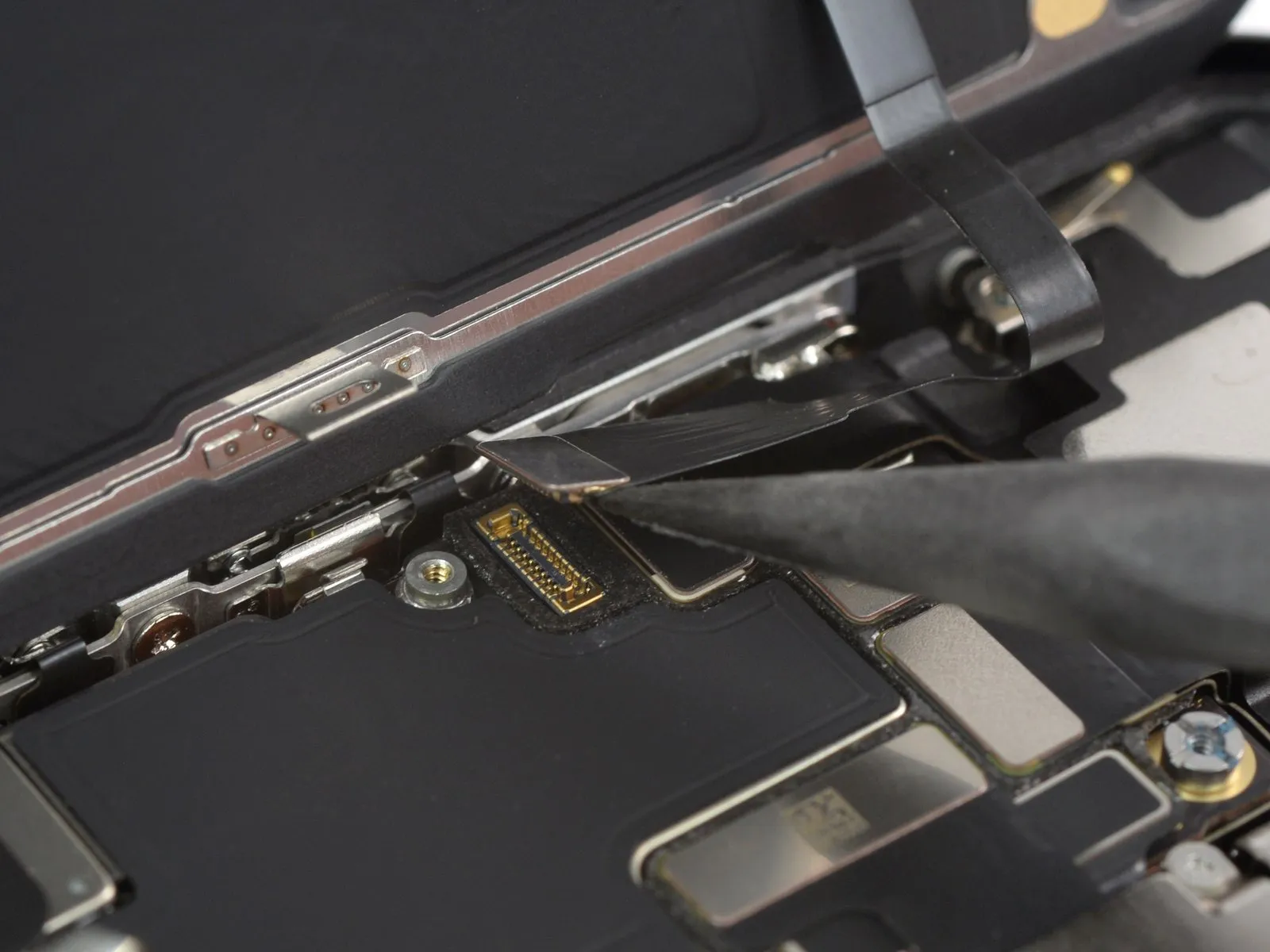
- To detach the second display cable, utilize the pointed end of a spudger, applying pressure to lift the connector vertically away from its socket.
Step 21 | Remove the screen
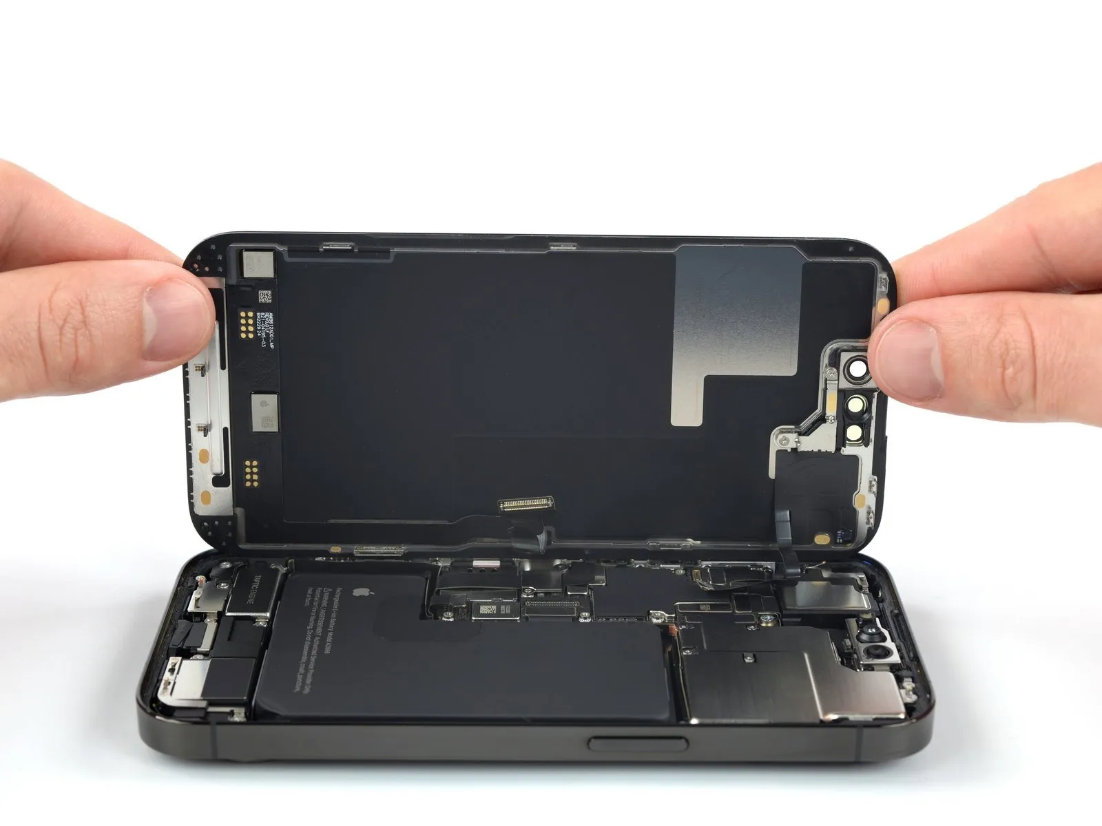
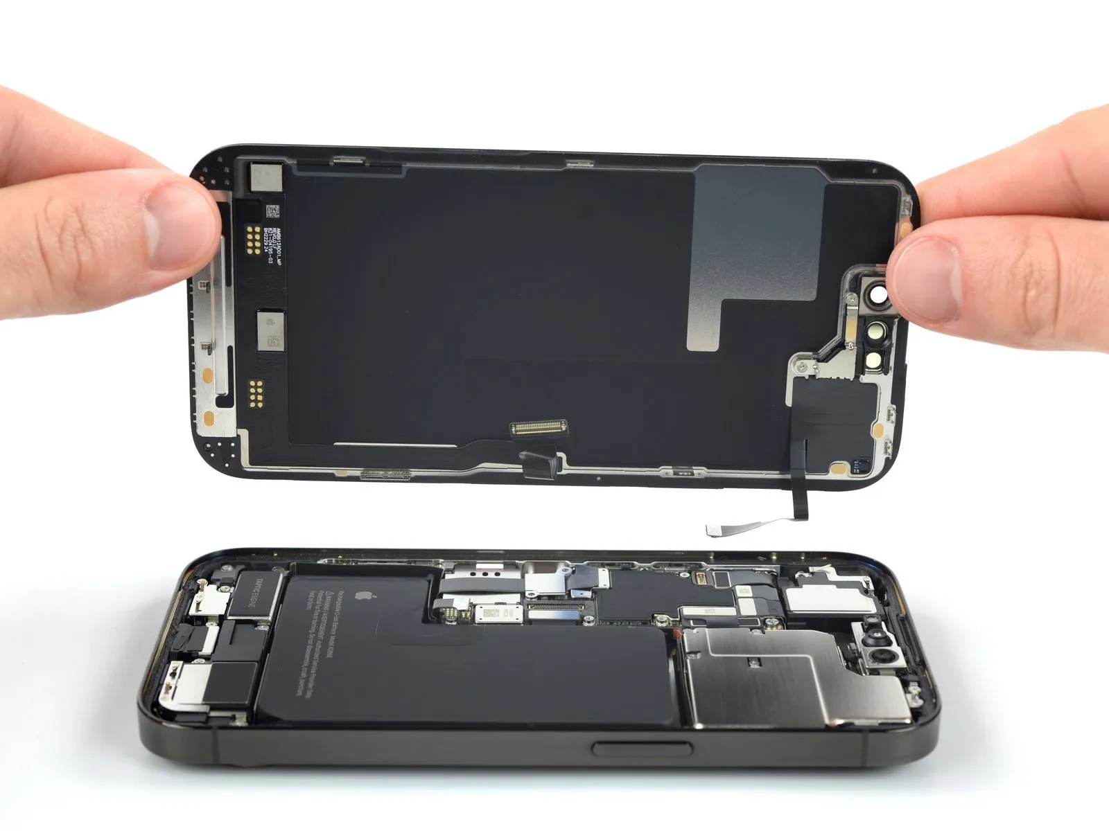
- Detach the display panel from the device's housing.
- Following a thorough cleaning of the contact surfaces utilizing isopropyl alcohol exceeding 90% purity, apply fresh adhesive material to ensure proper reattachment.
- Should you elect to substitute the existing screen adhesives during the reassembly process, halt at this stage to facilitate the replacement.
Step 22 | Unfasten the rear-facing camera assembly cover screws
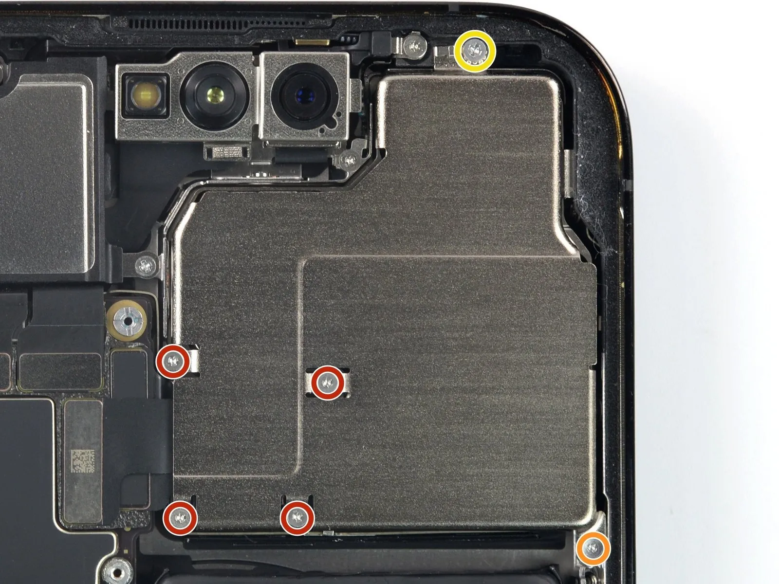
- Employ a Y000 driver to detach the five screws that hold the rear-facing camera assembly cover in place.Specifically, four screws, each measuring 1.5 millimeters in length, require a Y000 driver for removal.A single Y000 screw, with a length of 1.3 millimeters, also necessitates a Y000 driver for disassembly.
- To release the securing screw, a Phillips screwdriver is required.This single screw is fastened with a length of 1.7 millimeters.
- The rear camera cover is affixed with five fasteners, necessitating a Y000 driver for their removal.Five screws, all requiring a Y000 driver, secure the rear-facing camera assembly cover.
- The cover's retention is achieved through the use of five screws, which are best removed with a Y000 driver.A Phillips screwdriver is the appropriate tool for removing the single 1.7 mm screw.For disassembly, utilize a Y000 driver to address the five screws holding the camera cover.The camera cover is fastened using five screws, each requiring a Y000 driver for their removal.A Phillips screwdriver is the necessary tool to extract the one screw that measures 1.7 millimeters in length.
Step 23 | Remove the rear-facing camera assembly cover
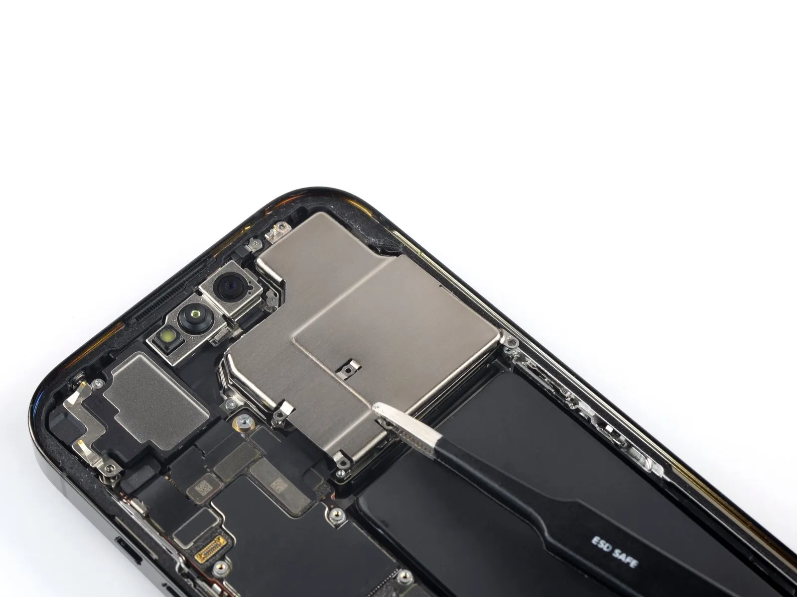
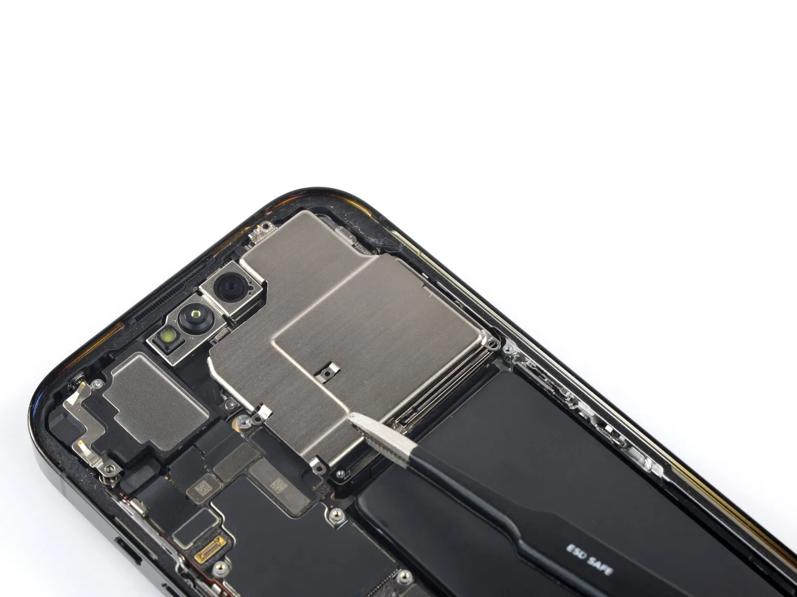

A diminutive metallic lip exists on the upper right portion of the rear camera cover, held in place by the device's chassis.
Employing tweezers, carefully grasp the rear camera cover.
Disengage the rear camera cover from the frame by shifting it in the direction of the volume controls, allowing the small metal edge to separate.
Detach the rear camera cover from the device.
When reassembling, ensure proper positioning of the rear camera cover and re-seat the small metal edge within its designated groove in the frame.
Step 24 | Disconnect the ultra wide and telephoto camera cable
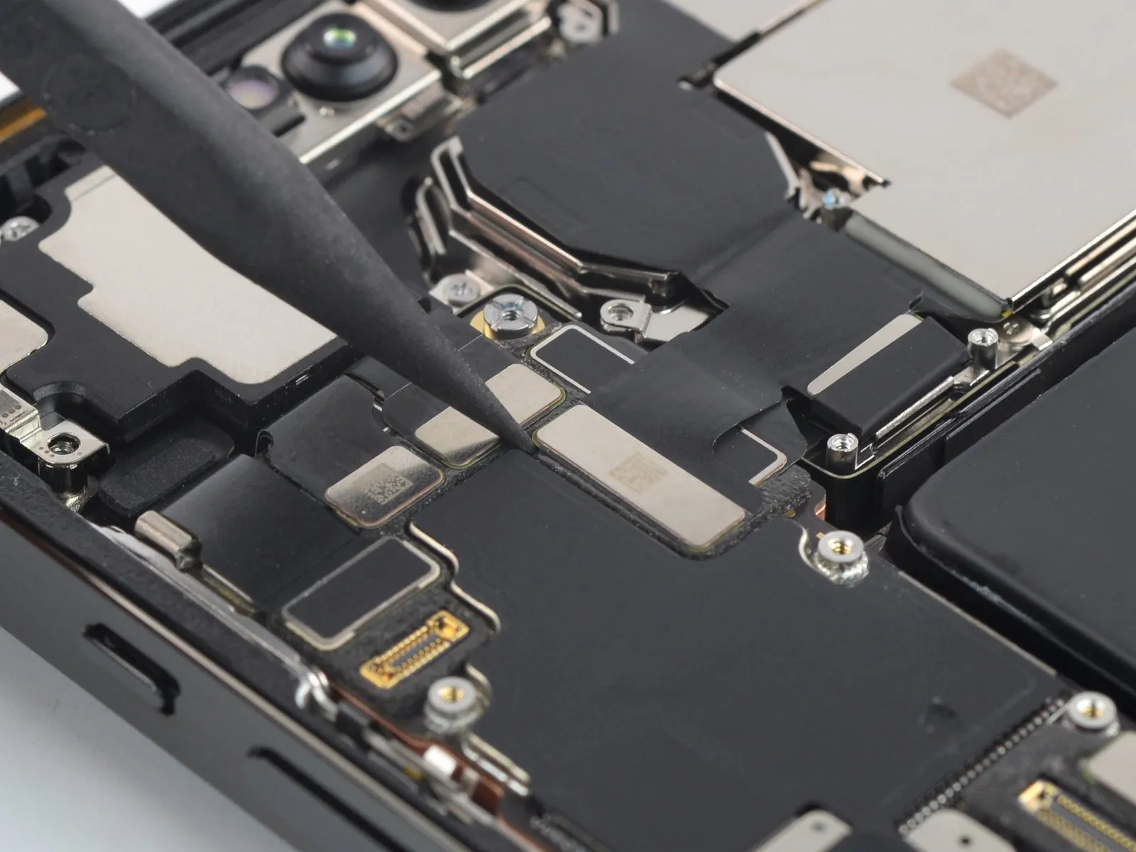
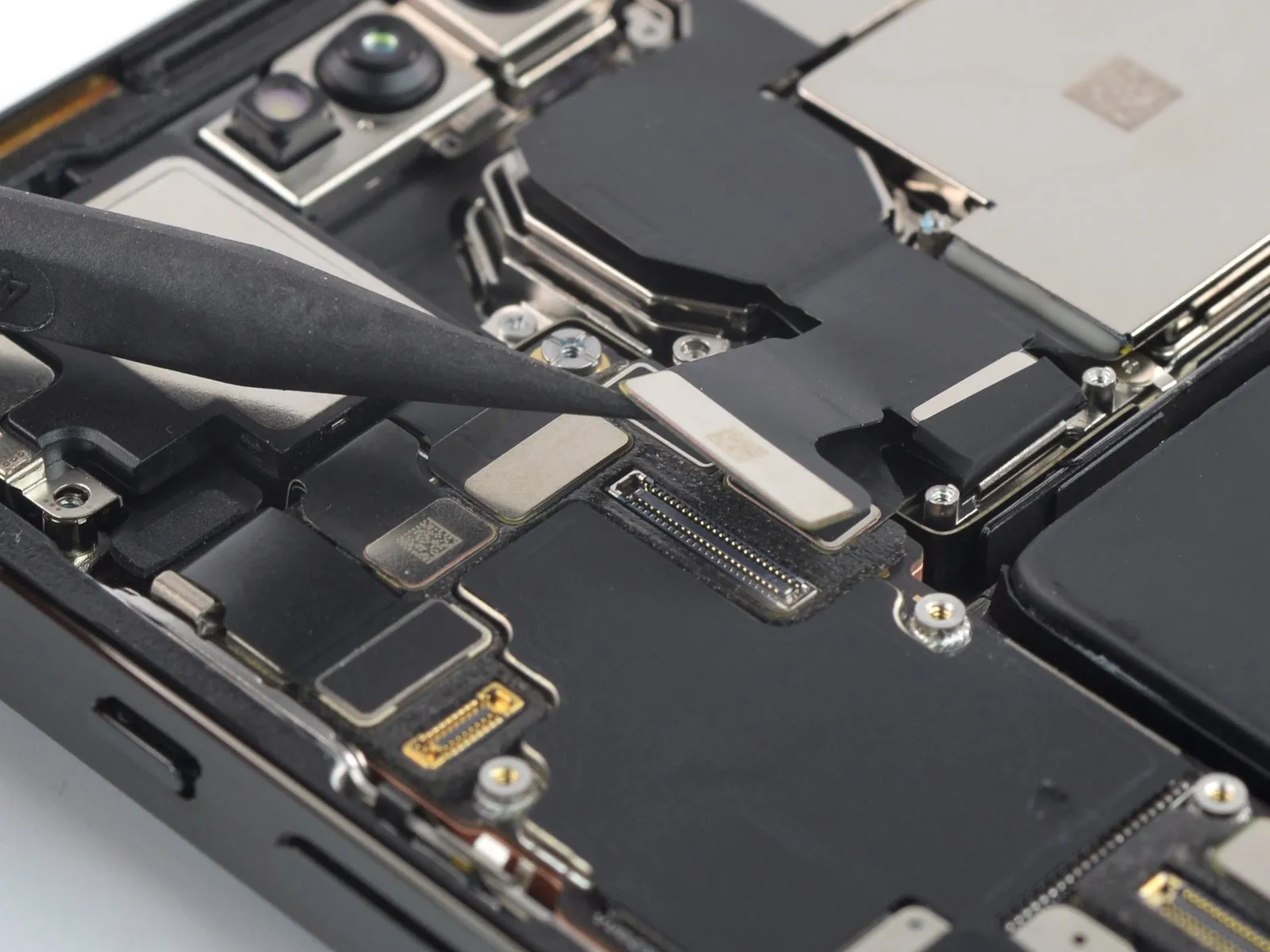
Employ a spudger to release the ultra wide and telephoto lens cable connectors, lifting them vertically from their respective sockets.The lens cable connectors should be detached using a spudger, ensuring a straight upward motion to avoid damage.To separate the ultra wide and telephoto lens cables, a spudger is required to gently pry the connectors upward from their receptacles.
Step 25 | Disconnect the wide lens camera cable
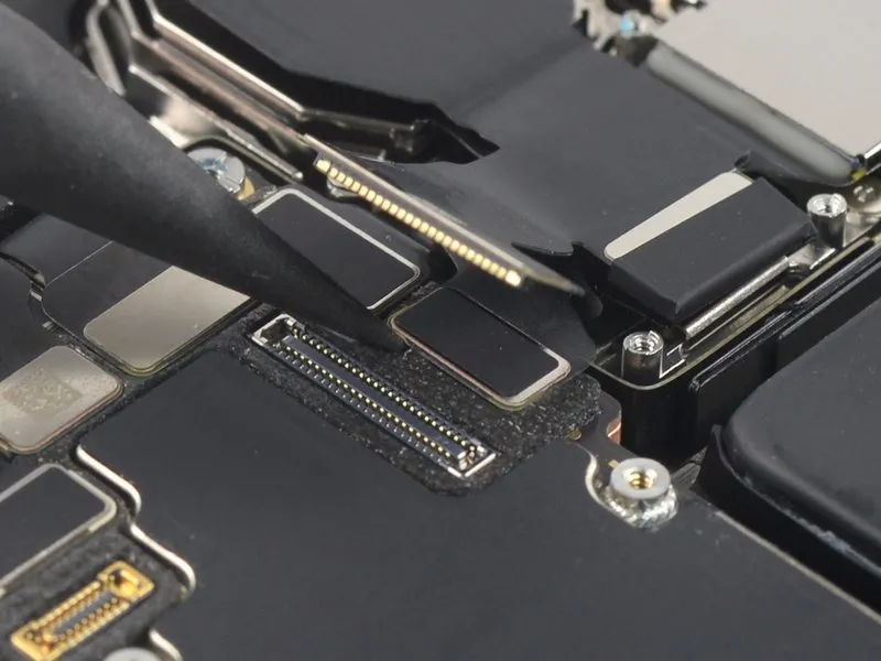
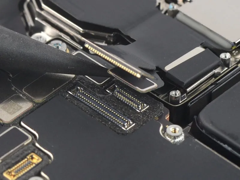
Employ a spudger to release the wide lens cable's connection, lifting the connector vertically away from its receptacle.The connector must be disengaged by applying upward force with the spudger, ensuring a straight trajectory to avoid damage.Carefully separate the wide lens cable from its socket using a spudger, maintaining a perpendicular lifting motion.
Step 26 | Pry up the rear-facing camera assembly
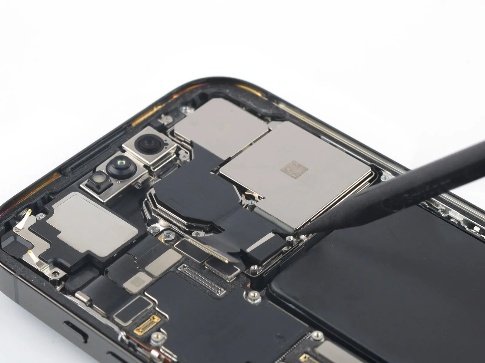
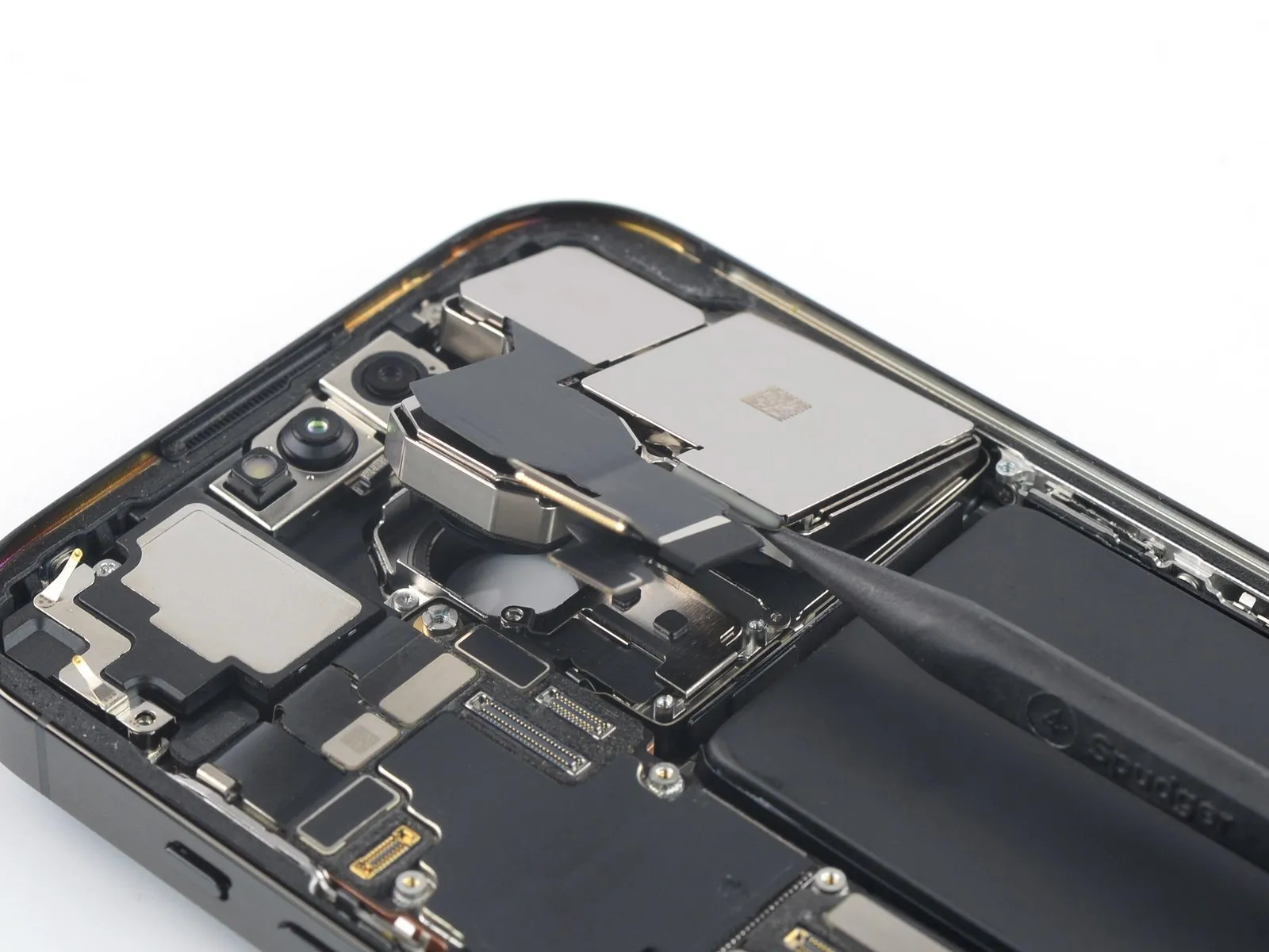
- Carefully slide the tapered end of a spudger tool between the lower edge and the rear camera housing.The spudger's tip should be positioned to access the gap beneath the camera assembly's bottom edge.Apply gentle upward force using the spudger to release the adhesive securing the rear-facing camera.
- This prying action will help to separate the camera assembly from the device's chassis.Maintain consistent pressure with the spudger to prevent damage to surrounding components.The goal is to disengage the adhesive bond without applying excessive force to the camera module.
Step 27 | Remove the rear-facing camera assembly
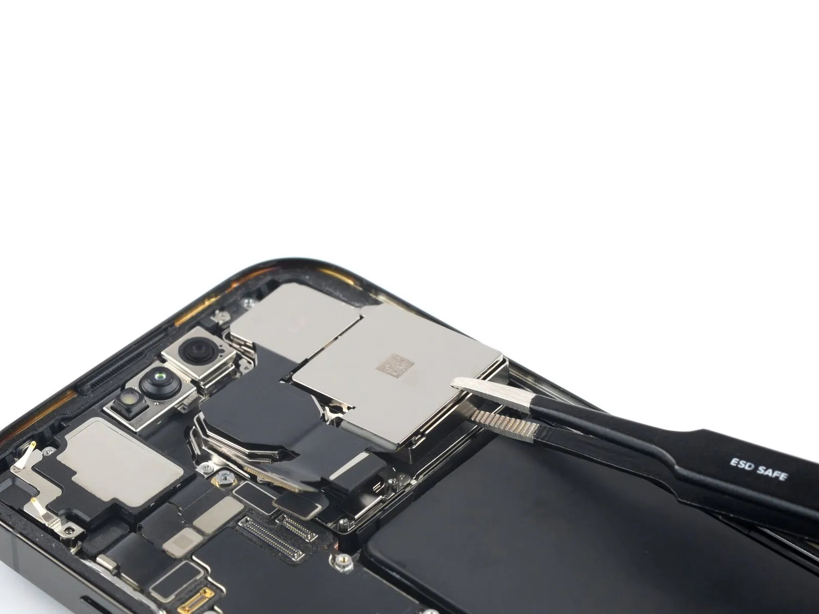
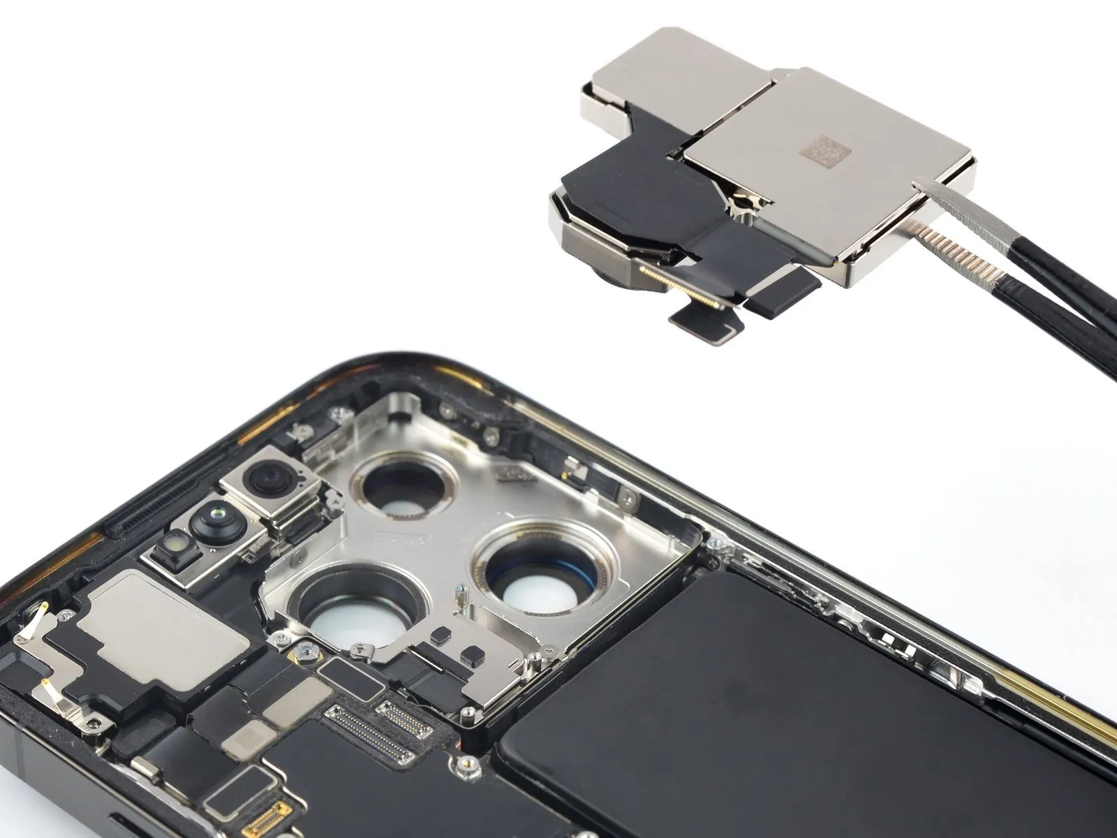
Employ tweezers or your fingertips to detach the rear camera module.
Step 28 | Unfasten the lidar sensor cover screw

Employ a standoff screwdriver to detach the fastener.The standoff screw, measuring 2.8 millimeters in length, requires removal.This screw's purpose is to hold the lidar sensor cover in place.A standoff screwdriver is the appropriate tool for this task.Carefully unscrew the 2.8 mm standoff screw to release the sensor cover.
Step 29 | Remove the lidar sensor cover


Step 30 | Disconnect the lidar sensor


Step 31 | Pry up the lidar sensor


- Utilize the planar extremity of a spudger.The spudger is required for this procedure.Position the spudger's flat end directly beneath the superior border of the lidar sensor.
- Apply upward force with the spudger.The spudger facilitates the separation of the lidar sensor.This upward pressure will disengage the lidar sensor's adhesive.
Step 32 | Remove the lidar sensor


- Employing a set of tweezers is necessary for the subsequent action.The tool required for this step is a pair of tweezers.Carefully extract the lidar sensor utilizing the tweezers.