iPhone 15 Pro Back Glass Replacement
This document provides instructions for the replacement or removal of a damaged rear glass component from an iPhone 15 Pro.Successful completion of this repair necessitates the use of fresh adhesive specifically designed for the back glass.A fractured or shattered rear enclosure necessitates these procedures to restore functionality and structural integrity.
Step 1 | Prepare your iPhone for disassembly

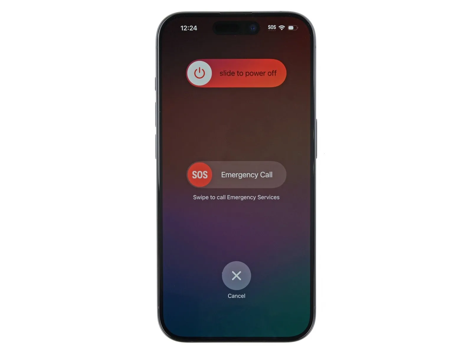
- To initiate the shutdown sequence, simultaneously press and maintain the power button alongside either volume button, then swipe to power off the phone.
- A critical safety precaution necessitates complete disconnection of all external cables from the phone before any repair work begins.
Step 2 | Tape over any cracks
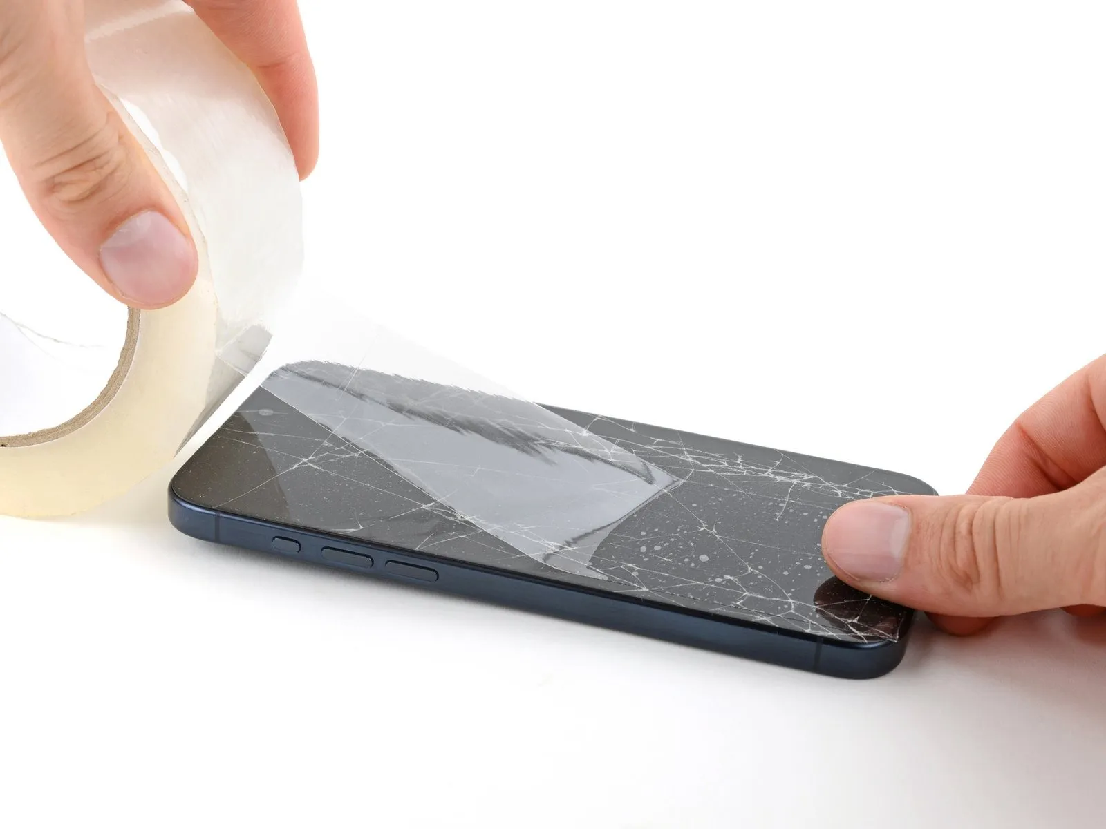
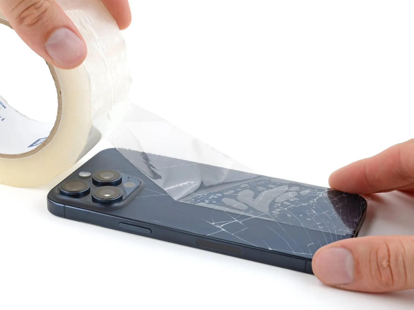
- This protective taping measure serves to safeguard against cuts while simplifying the device's separation into its component parts.
Step 3 | Mark your opening picks


- Using a measuring tool, determine a distance of3 millimetersfrom the tool's distal end and apply a permanent marking agent to the separation tool.
- For enhanced reference, consider applying distinct markings at other points on the tool, each representing a different measurement.
- As an alternative method, affix a coin to the separation tool's tip, positioning it3 millimetersfrom the extreme end.
Step 4 | Remove the pentalobe screws

Step 5 | Heat the bottom edge

- Avoid excessive heating of the device, as temperatures exceeding safe limits pose a risk.The internal battery is vulnerable to damage from elevated temperatures.
Step 6 | Insert an opening pick
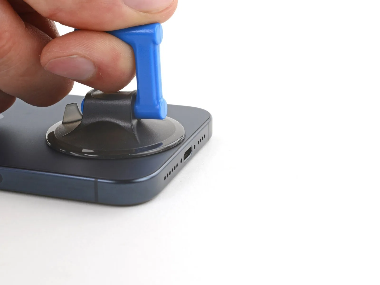


- Securely attach a suction cup to the lower border of the rear glass panel.
- Exert a consistent and considerable upward pull on the suction cup to generate separation between the rear glass and the device's frame.
- Carefully introduce the pointed end of a prying tool into the newly formed space.
Step 7 | Back glass information

Exercise caution when separating the rear glass with a cutting tool in subsequent procedures, as the wireless charging cable is located in close proximity to the volume buttons.
Step 8 | Separate the bottom edge adhesive


- Ensure the initial insertion of your opening tool does not exceed a depth of 5 millimeters from the lower border.Employ a reciprocating motion with your tool across the lower edge to sever the adhesive bond.Maintain the tool's position within the lower-left corner to inhibit the adhesive from reforming a seal.
- The adhesive's separation is achieved through a back-and-forth movement of the tool along the bottom edge.
- To avoid re-adhesion, keep the opening pick situated in the lower-left corner.
Step 9 | Heat the left edge

To facilitate separation, apply heat to the left lateral border of the rear glass panel until its surface temperature is sufficient for tactile perception.
Step 10 | Separate the left edge adhesive
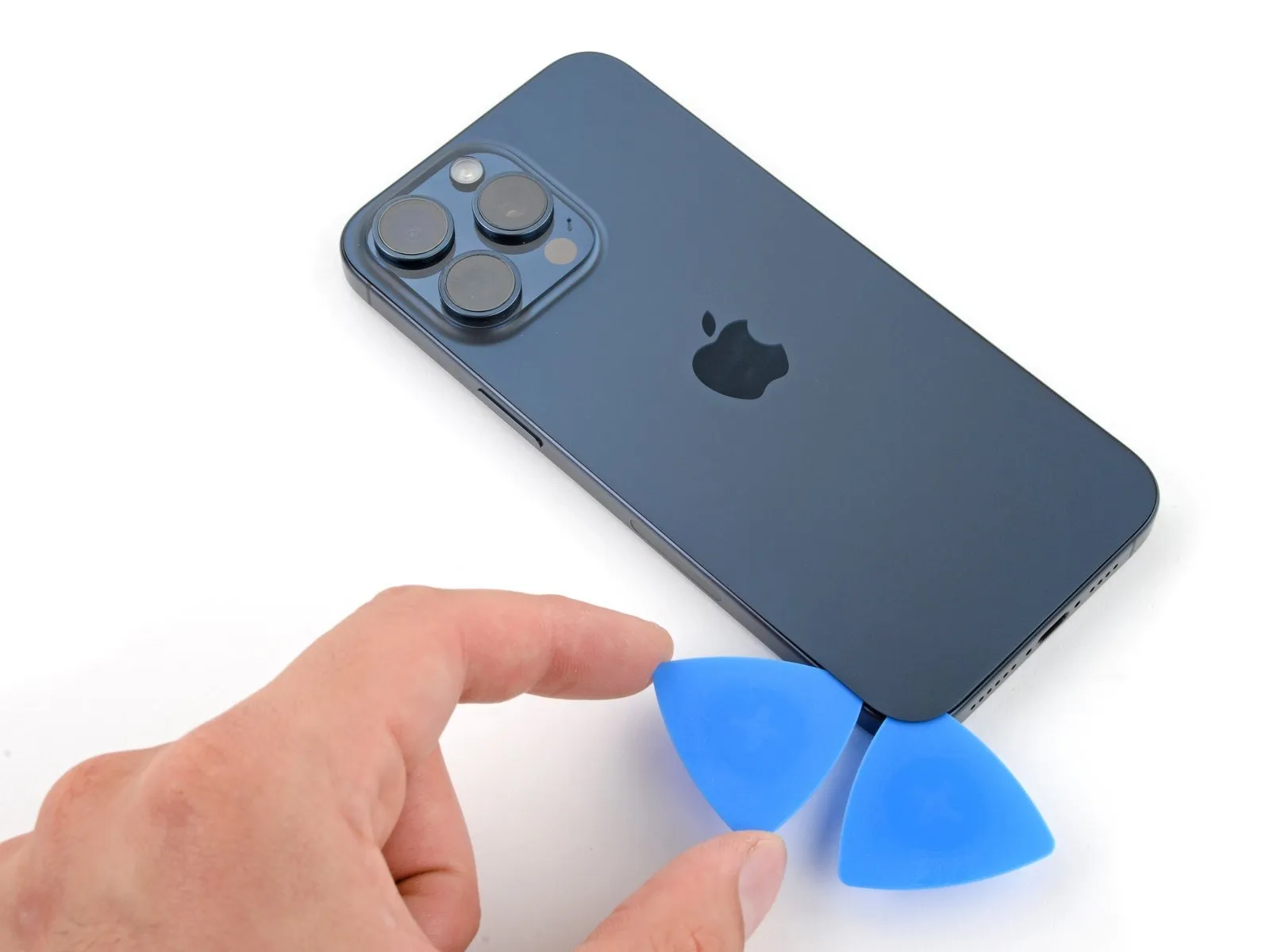

- Ensure the insertion depth of the tool remains limited to a maximum of 5 mm, specifically along the left border.Introduce a supplementary opening tool positioned to the left of the initial insertion point.Move this second tool towards the upper-left corner of the rear glass panel, facilitating separation of the left-side adhesive.
- Maintain the position of this tool, keeping it in place to hinder re-adhesion of the separated adhesive.
- The maximum allowable penetration of the tool is 5 millimeters, measured from the left edge.
- A second tool should be introduced, strategically placed to the left of the first, to aid in adhesive separation.
Step 11 | Heat the top edge
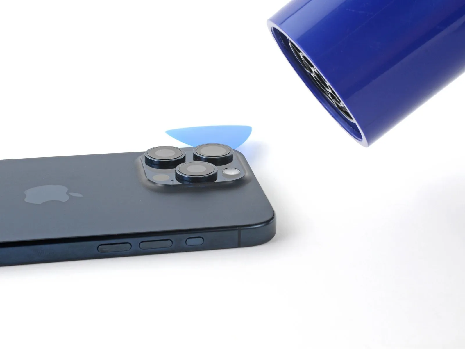
To facilitate separation, apply heat to the upper perimeter of the rear glass panel until its surface reaches a temperature that is comfortable to touch.
Step 12 | Separate the top edge adhesive
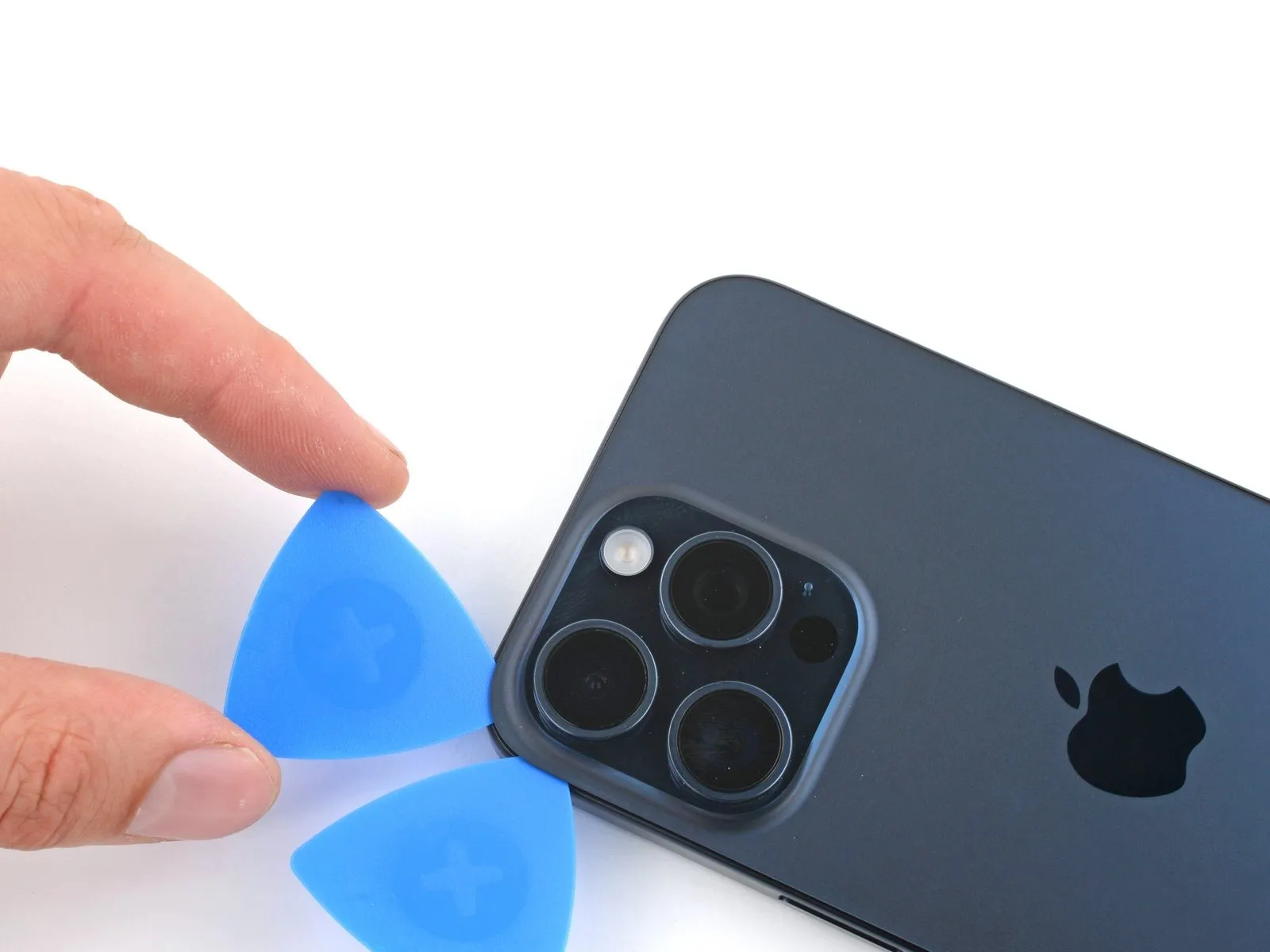


Limit pick insertion depth to a maximum of 5 millimeters.Continue along the uppermost border.
Position a third opening pick within the upper-left quadrant of the rear glass assembly.
Move the pick across the top surface to sever the adhesive bond.
Should the adhesive along the top edge of the rear glass remain adhered, the retaining clips might be obstructed; utilize theplanar terminus of a spudgerto apply inward pressure on the clips until disengagement occurs.
Step 13 | Separate the top right corner adhesive

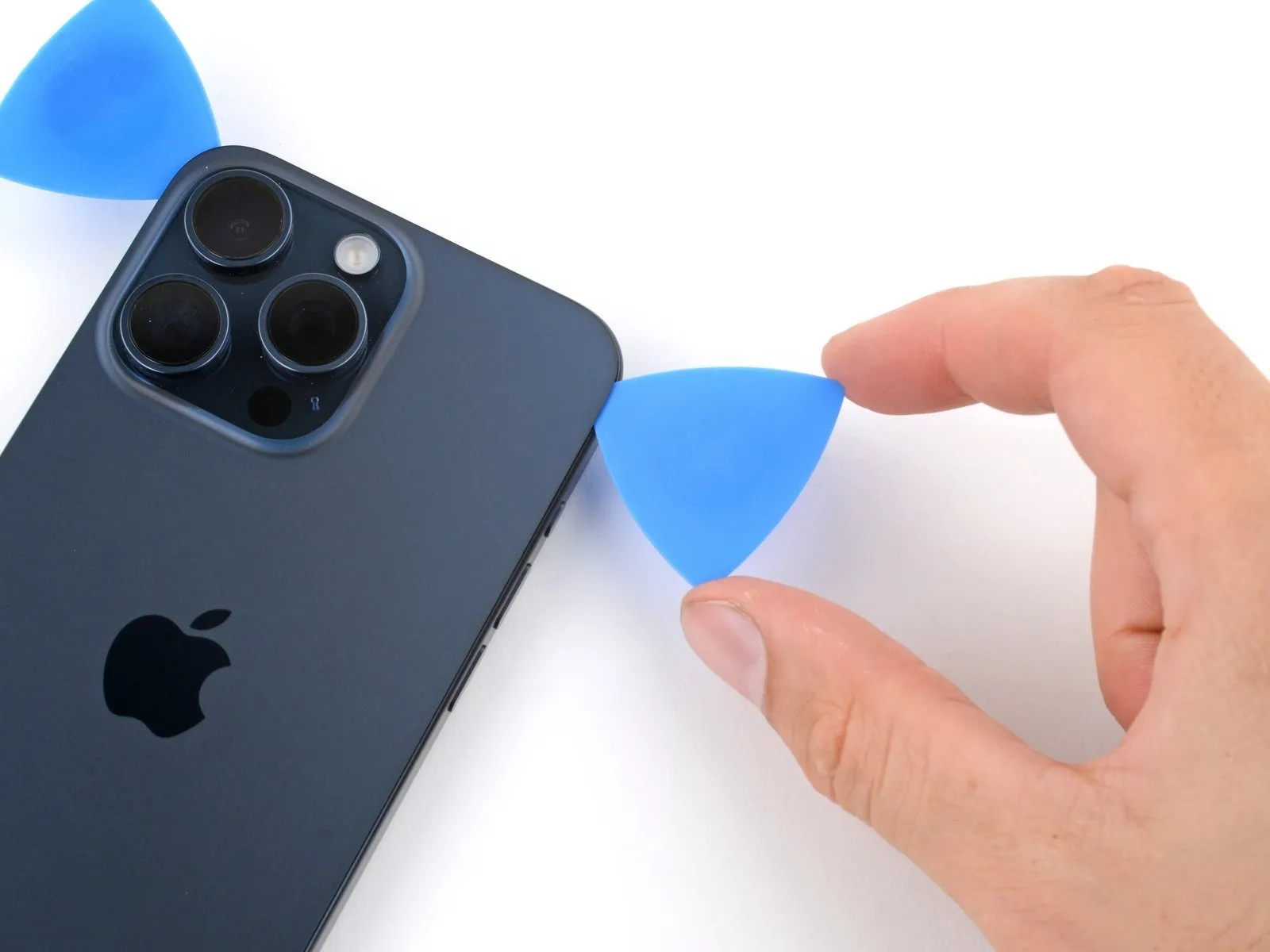
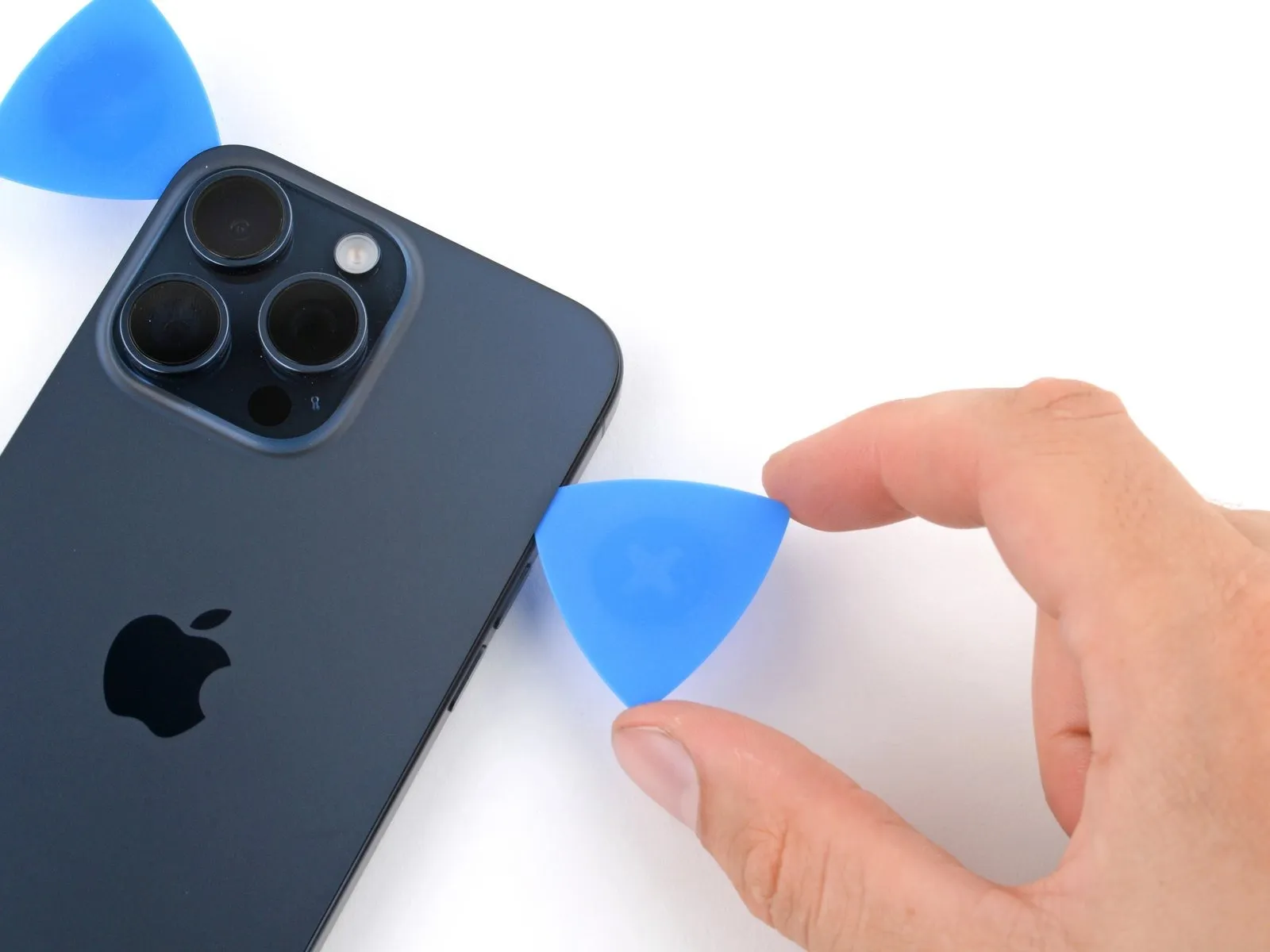
- To prevent damage to the wireless charging cable, ensure your prying tool does not extend beyond the volume up button's location.
- Employ a rotating motion with your prying tool around the upper-right edge of the rear glass panel.
- Advance your prying tool until it reaches the volume up button's position.
- Maintain the inserted prying tool in its current location to inhibit the adhesive layer from reforming.
Step 14 | Heat the right edge
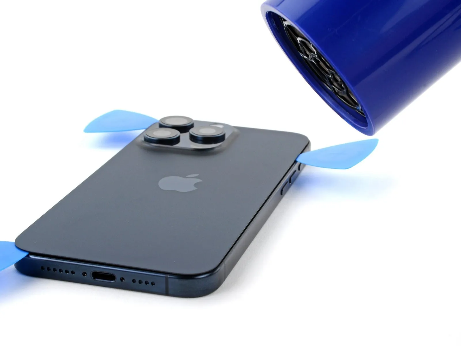
Step 15 | Separate the right edge adhesive
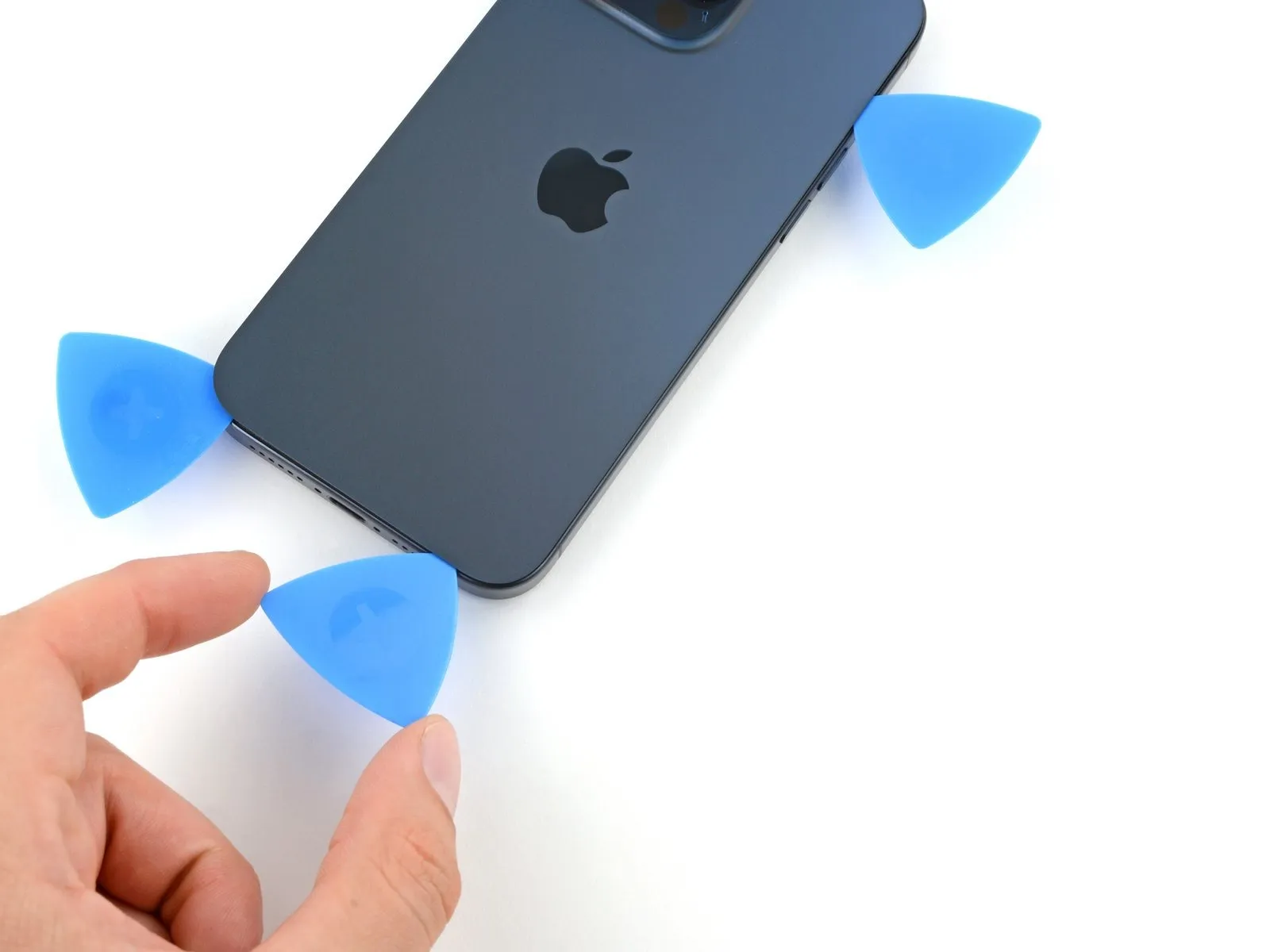


- To prevent damage to the wireless charging cable, ensure your pick does not extend beyond the volume down button's location during separation.
- Introduce a fourth opening pick positioned along the lower edge of the rear glass assembly.
- Perform a rotational motion with your pick, focusing on the lower-right corner of the rear glass.
- Advance your pick's insertion point until it reaches the volume down button.
Step 16 | Swing open the back glass
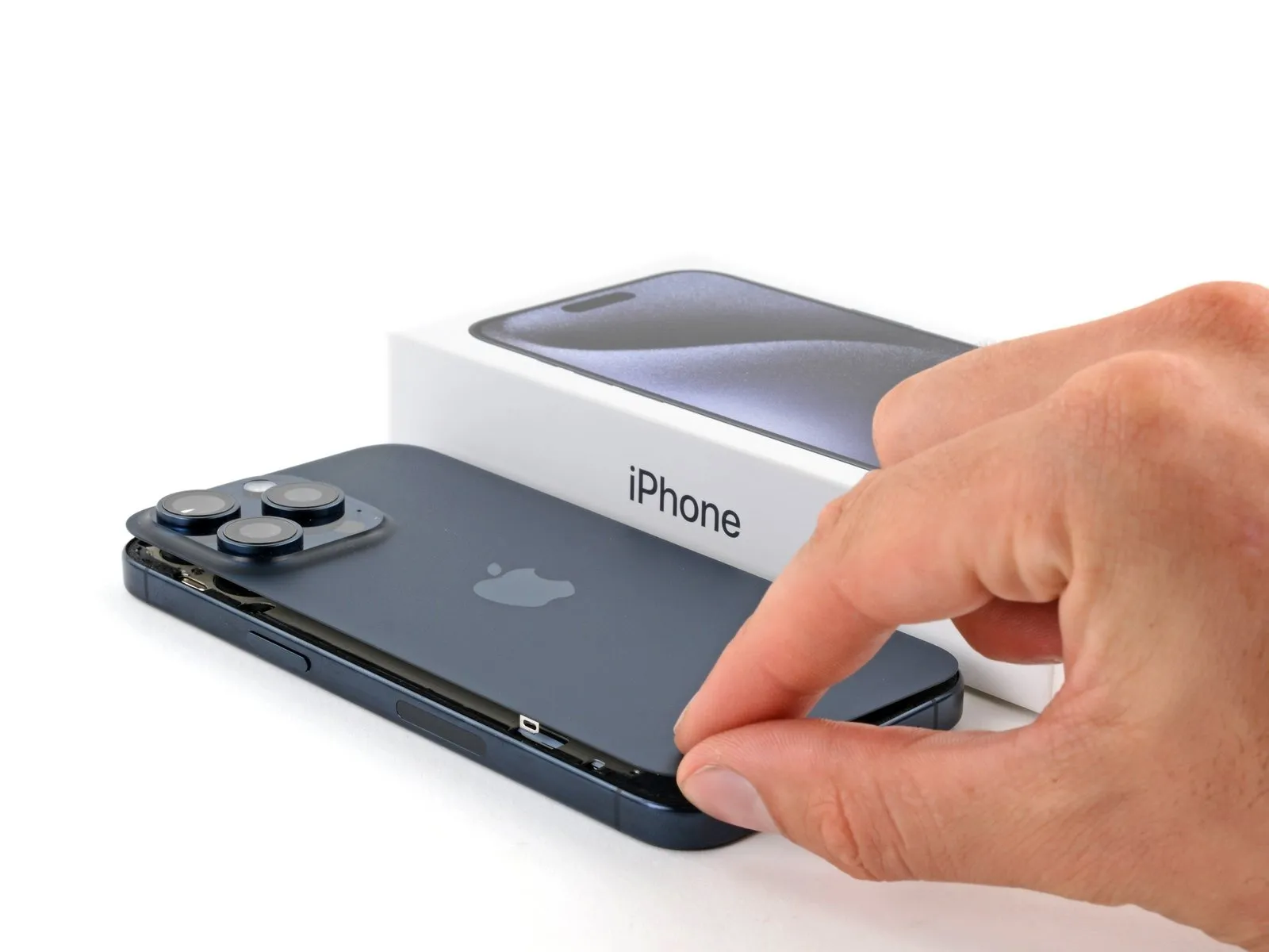


- Carefully pivot the rear glass assembly away from the device's right side.
- Should the rear glass exhibit resistance during separation, re-examine the entire outer boundary to identify any remaining adhesive or secured clips.
- Position the detached rear glass against a supporting structure, such as a container, to prevent undue stress on the connecting cable.
Step 17 | Remove the wireless charging connector cover
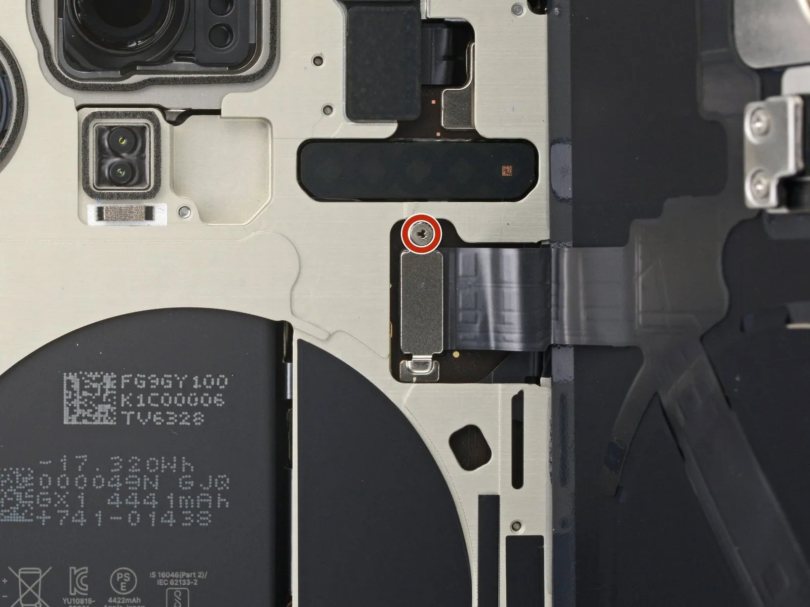


- Employ a tri-point Y000 driver for the screw removal process.The screw, measuring 1.0 mm in length, requires a tri-point Y000 driver for its extraction.A tri-point Y000 driver is essential for loosening the screw that holds the wireless charging connector cover in place.Carefully slide the cover away from its position on the logic board using tweezers.To detach the wireless charging connector cover, utilize tweezers to maneuver it out of its designated slot.
- After sliding, completely detach the wireless charging connector cover from the logic board.
Step 18 | Disconnect the wireless charging coil
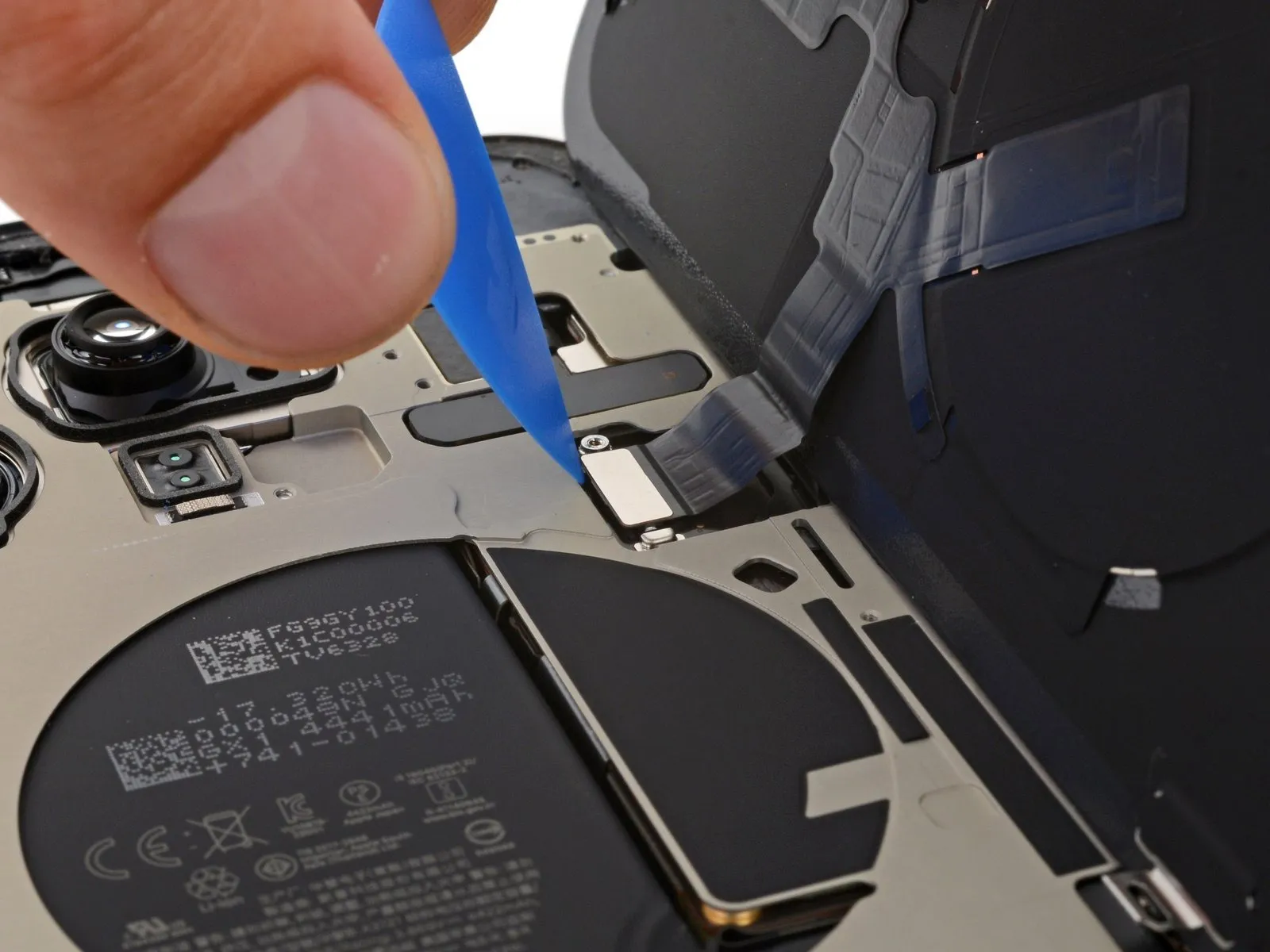

- Employ the pointed end of a plastic opening pick to release the wireless charging coil's press connector by levering it upwards and separating it.The press connector's connection is achieved by carefully positioning it atop its corresponding socket, followed by a controlled downward force on one edge until a distinct click is heard.To ensure a secure connection of a press connector, apply gentle pressure to one lateral surface until a positive locking sound is produced.
- Following the initial click, a second downward pressure must be applied to the opposing lateral surface to finalize the press connector's attachment.
Step 19 | Remove the back glass
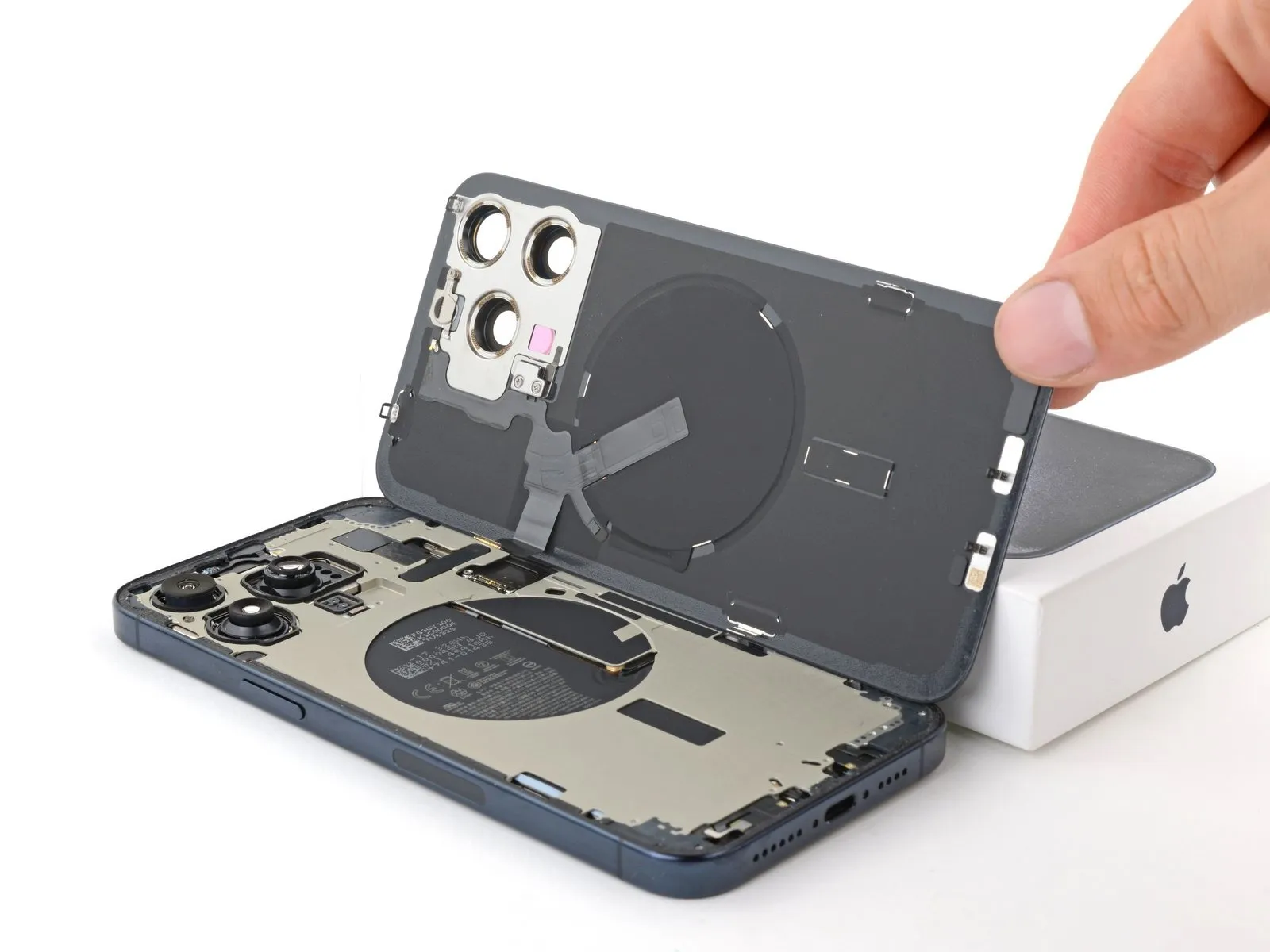

Step 20 | Disassembly complete
Successful completion of the device's separation is acknowledged.The subsequent instructions detail the procedures necessary for reassembling the iPhone.
Step 21 | Remove the back glass adhesive

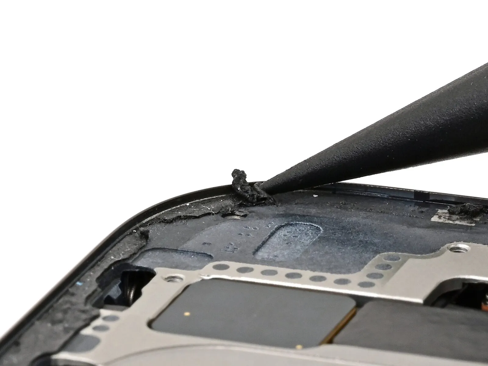
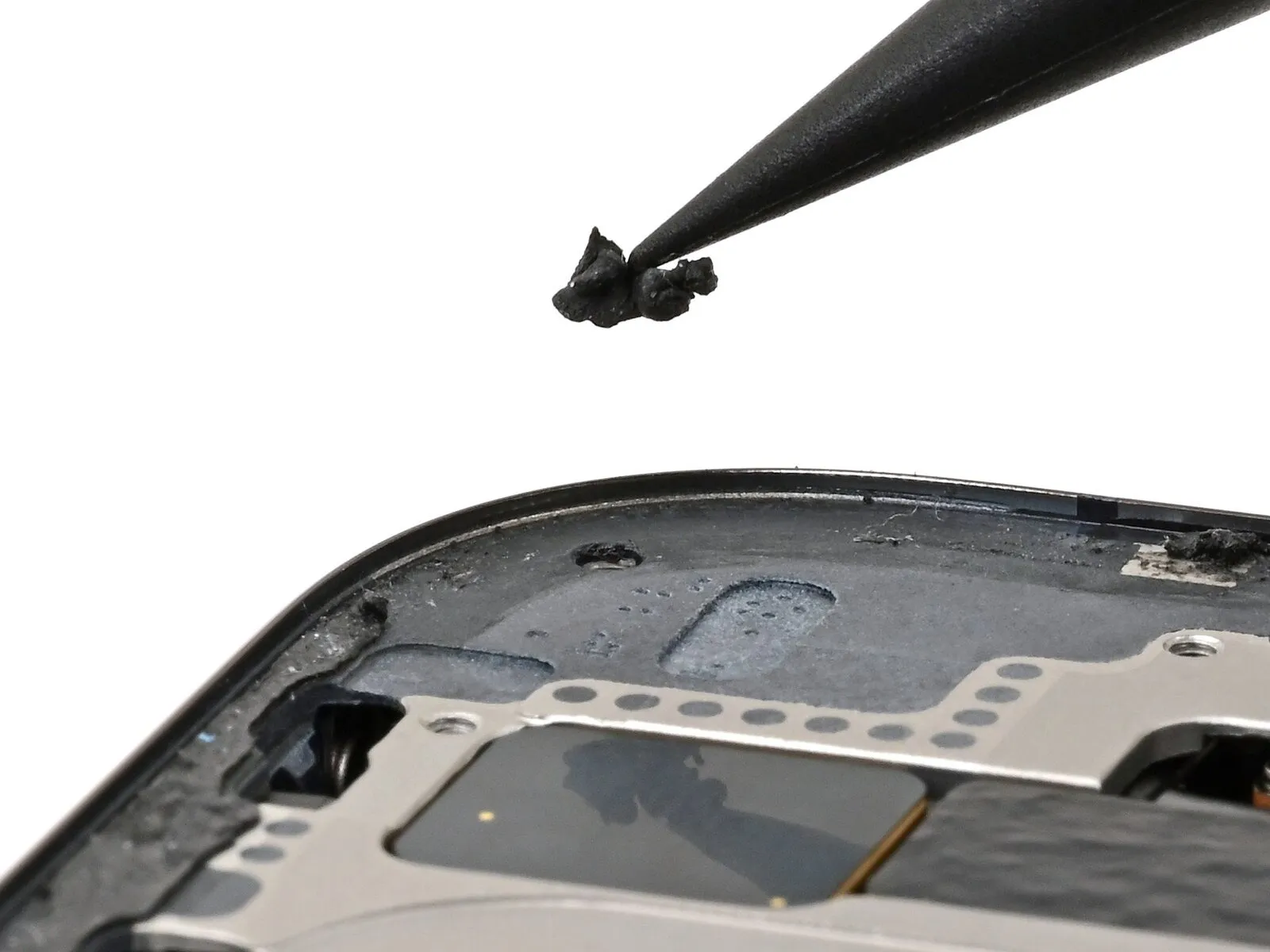
- Due to its high tack, separating the rear glass from the device may require a significant amount of time.
- Employ the tip of a spudger to gather and detach larger adhesive areas.To ease removal, apply heat using a hairdryer or heat gun to reduce the adhesive's viscosity.Continue this procedure until all substantial adhesive segments are detached.
- The rear glass adhesive possesses considerable stickiness, potentially prolonging the separation process.
- A spudger's pointed end can be utilized to consolidate and liberate larger adhesive portions from the frame.
Step 22
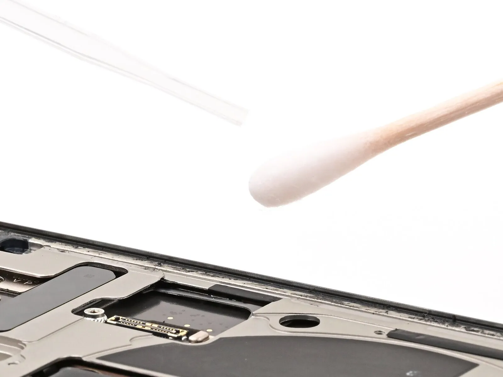


- To dissolve leftover adhesive, introduce a small quantity of adhesive remover, or isopropyl alcohol with a concentration of at least 90%, onto a cotton swab or coffee filter.The selected solvent should be applied using a cotton swab or coffee filter to facilitate precise application.Residual adhesive on the frame's surface must be eliminated to ensure proper component functionality and aesthetics.
- Employ the solvent-soaked swab or filter to carefully remove any traces of adhesive from the frame.
Step 23
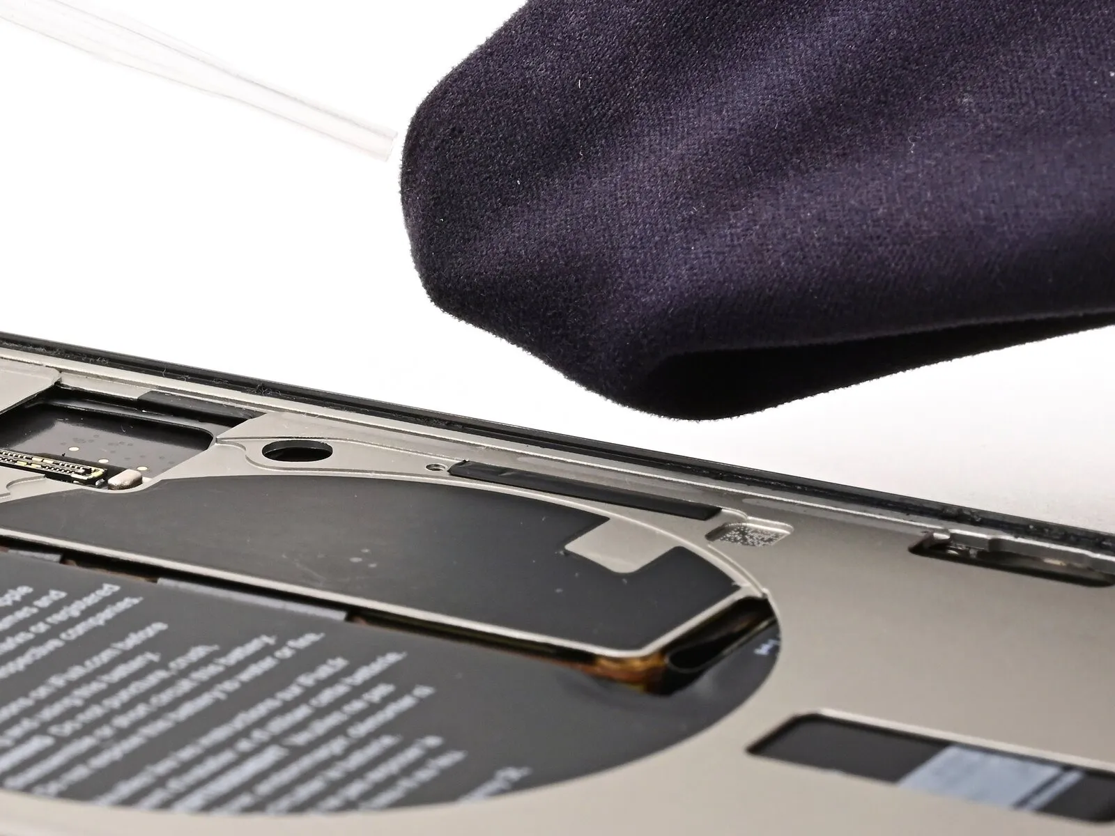


- To prepare the frame's surface for fresh adhesive, utilize a clean, lint-free cloth or coffee filter dampened with a small quantity of adhesive remover or isopropyl alcohol possessing a concentration of at least 90%.Residual adhesive must be completely eliminated from the frame's surface through thorough wiping with the prepared cloth or filter.Employing adhesive remover or high-grade (90%+) isopropyl alcohol is essential for surface preparation, ensuring optimal adhesion of the replacement adhesive.
Step 24 | Orient the replacement adhesive
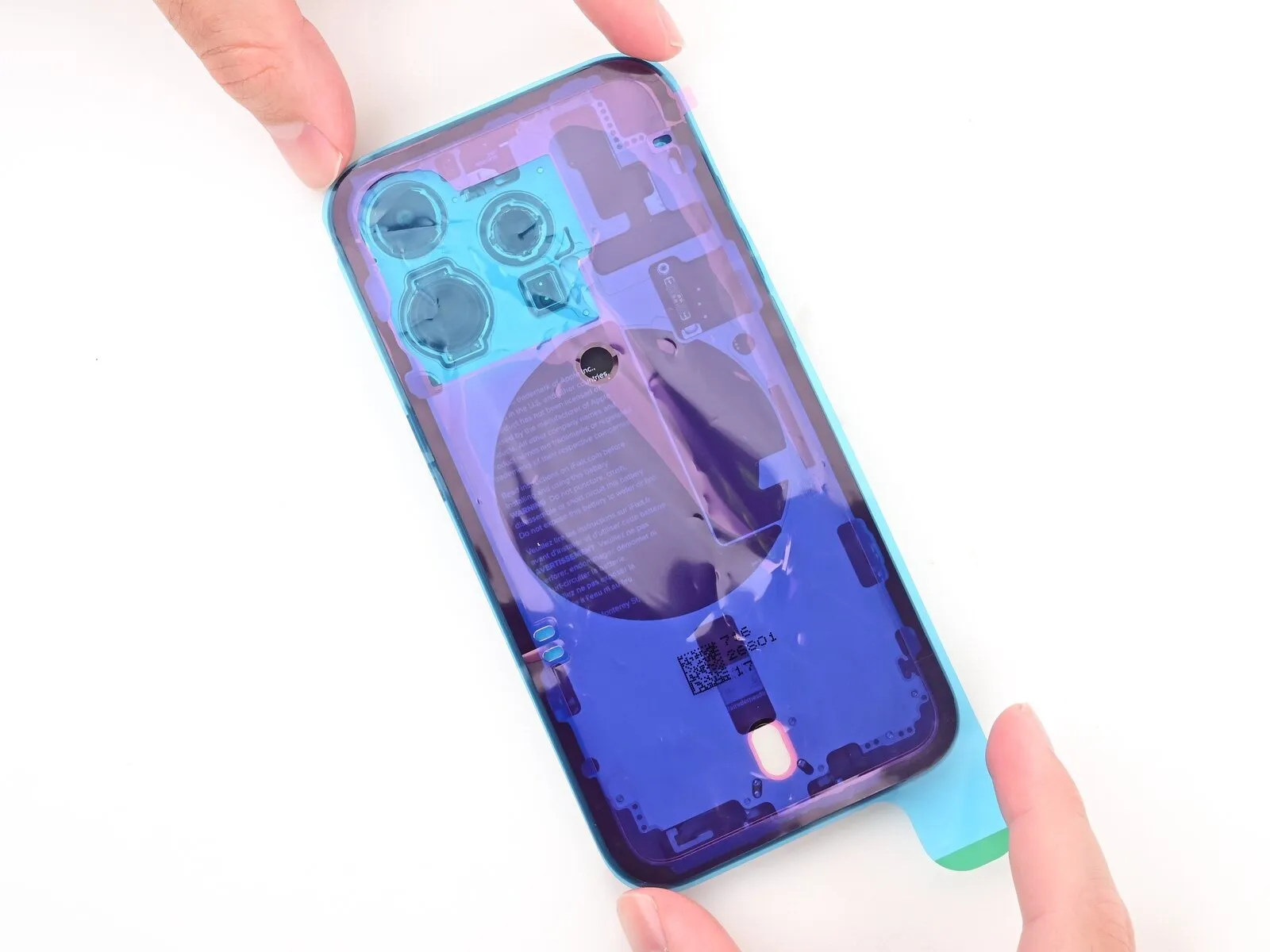
- To ascertain proper placement, position the adhesive sheet onto the frame's surface without removing any protective liners.The adhesive sheet's alignment should be confirmed by observing its relationship to existing frame features.Utilize elements like the camera aperture and edge indentations to mentally simulate the adhesive's contact area on the frame.
- Visual assessment of these frame details facilitates accurate adhesive sheet orientation prior to application.
Step 25 | Apply the replacement adhesive
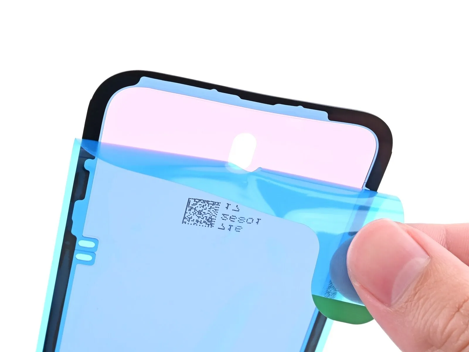
- Initiate the separation process by grasping the prominent tab located at the lower edge of the adhesive backing, subsequently removing the protective liner to reveal the surface intended for frame adhesion, but avoid complete removal.
- Exercise caution, as the revealed adhesive possesses significant tackiness; prevent unintended contact with surfaces until the application to the frame is prepared.
- Should your adhesive incorporate several liners, carefully peel away only the liner that exposes the adhesive surface designed for attachment to the frame.
Step 26
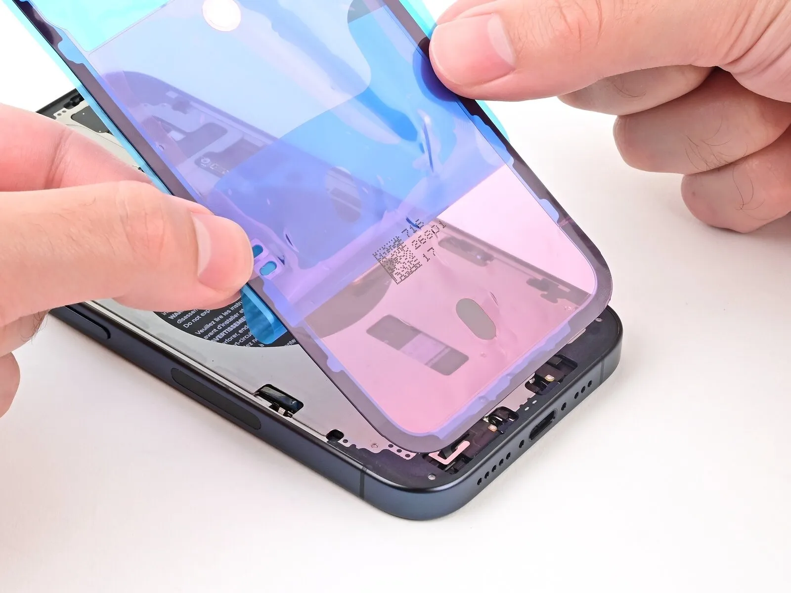


- After the adhesive has fully cured, repositioning is impossible, necessitating removal and reapplication with fresh adhesive.
- Maintain the back liner's separation to permit precise alignment of the adhesive's exposed edge with the iPhone's lower frame boundary.
- Following proper alignment, gently place the adhesive onto the bottom edge of the iPhone's frame.
Step 27
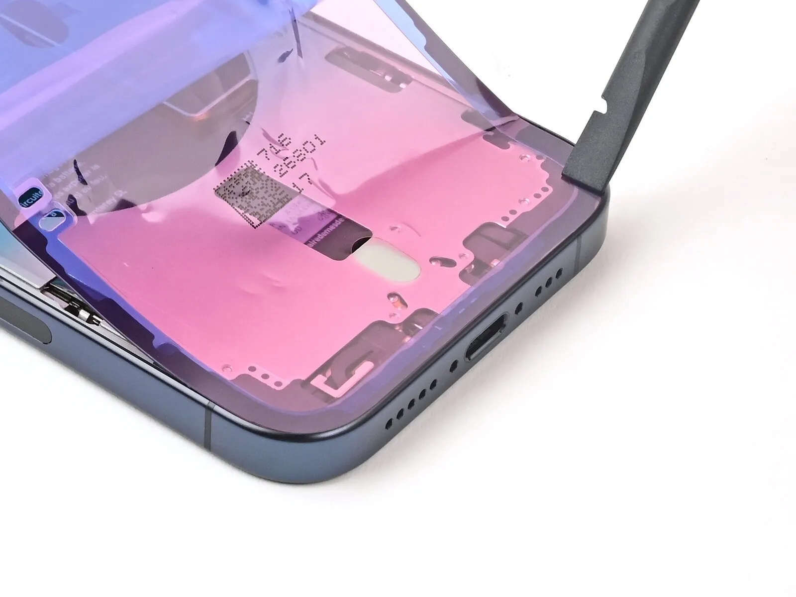

Employ the planar extremity of a spudger tool to secure the adhesive bond by applying pressure along the inferior margin.The adhesive's adhesion can be reinforced by utilizing the flat side of a spudger to apply even pressure across the lower edge.To ensure proper adhesion, use the flat end of a spudger and apply pressure to the adhesive situated along the device's bottom edge.
Step 28
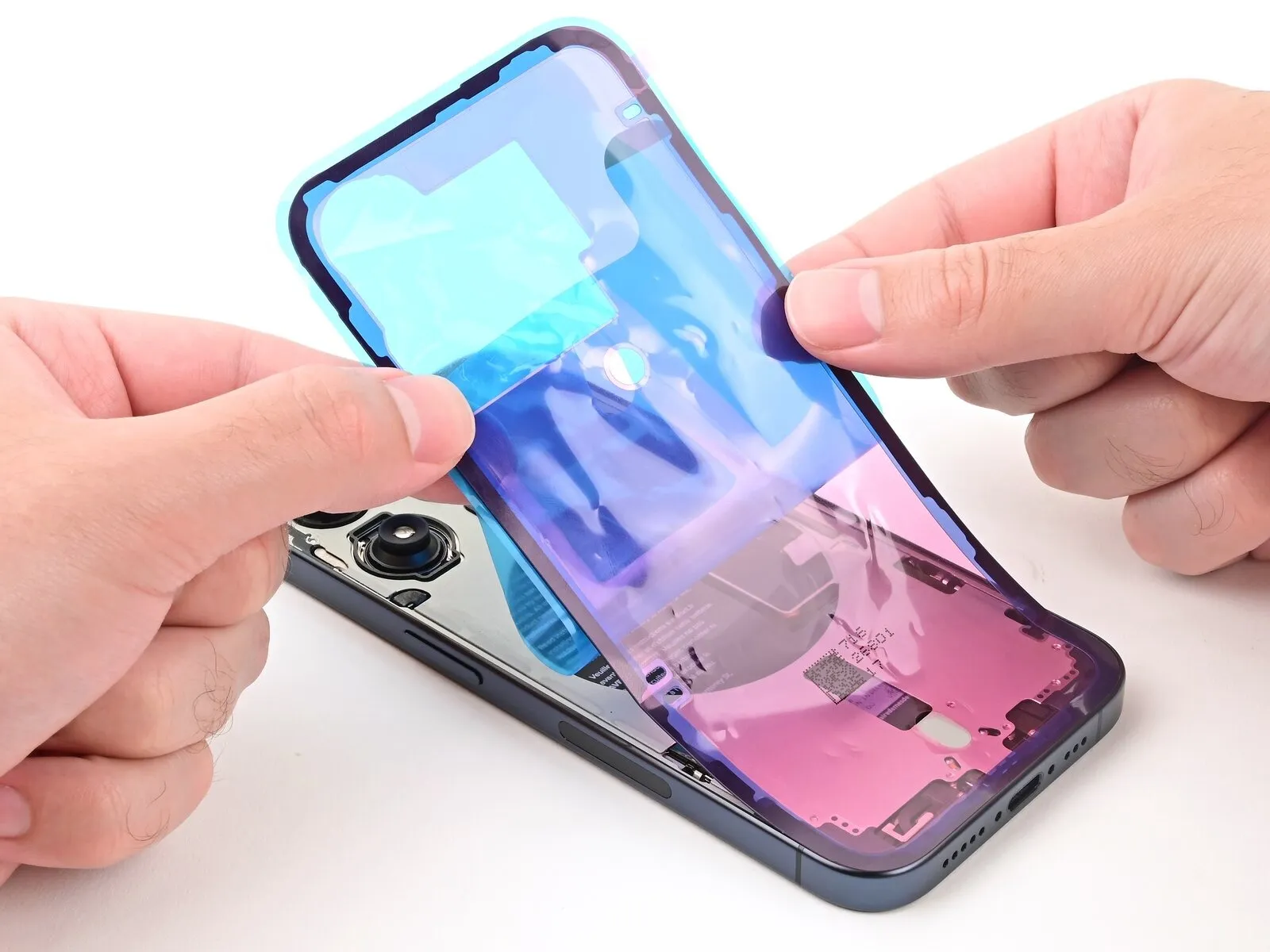


- Carefully detach the protective backing from the adhesive strip, positioning the adhesive along the iPhone's perimeter.
- Proper alignment of the adhesive's lower edge should ensure a precise fit along the side and top edges; otherwise, discard the adhesive and repeat the process with a fresh strip.
- While reassembly without adhesive is possible if a replacement isn't immediately available, understand that the iPhone's water resistance will be compromised until new adhesive is applied.
Step 29 | Press the adhesive into place
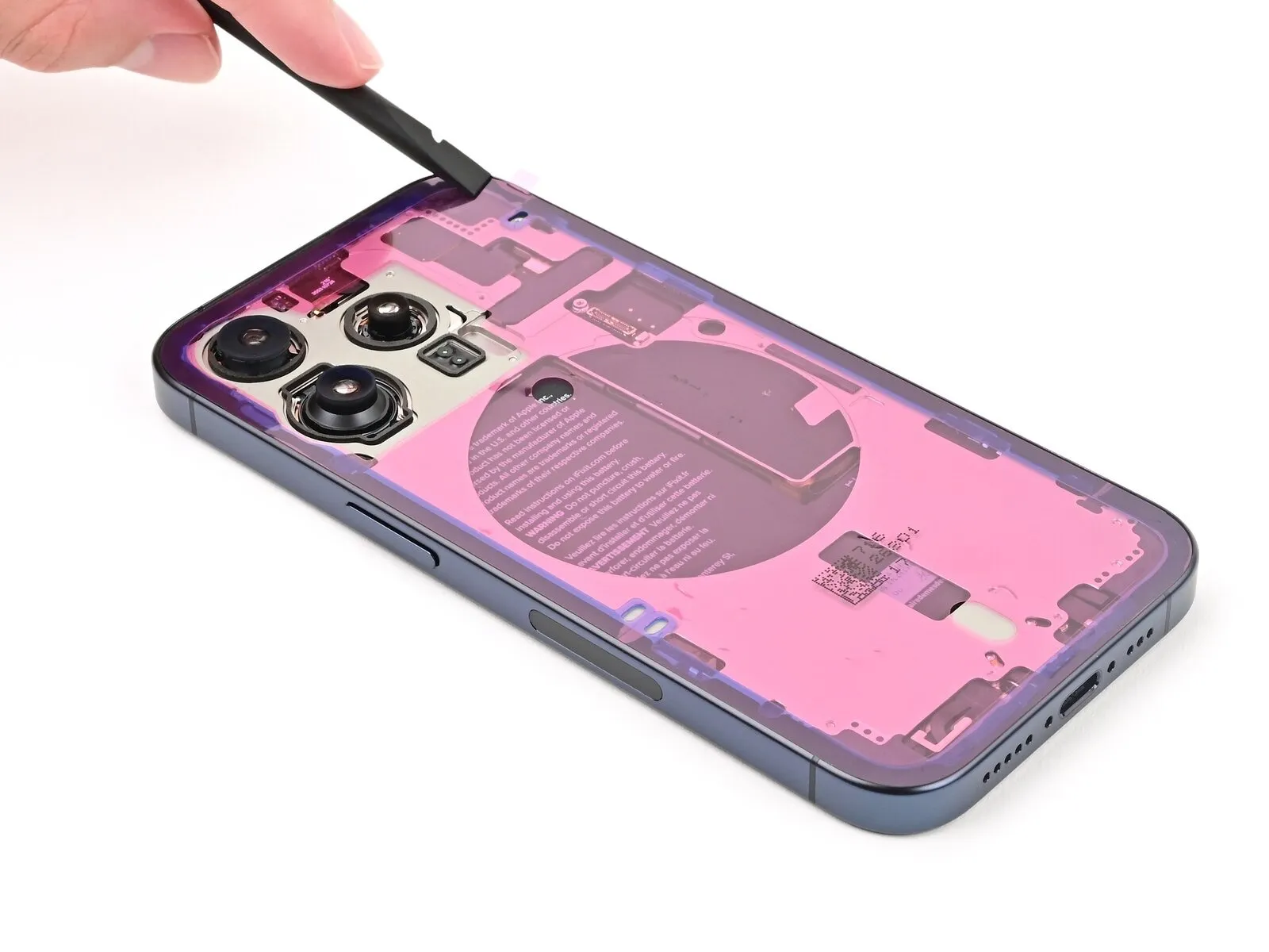


Step 30 | Remove the top liner
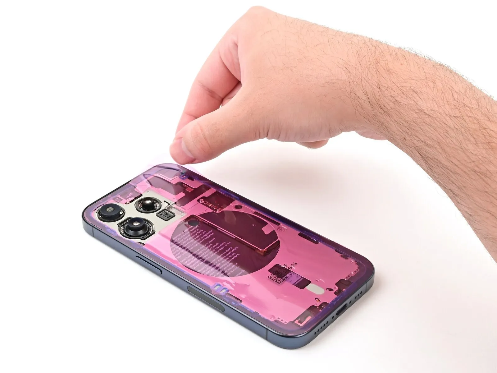


- To detach the uppermost protective covering, elevate the designated pull tab situated in the frame's upper-right quadrant, subsequently separating and discarding it.
- The positioning of your pull tab might vary; confirm that you are releasing the complete, full-sized top liner, rather than the thinner liners found along the perimeter.
Step 31 | Adhesive information
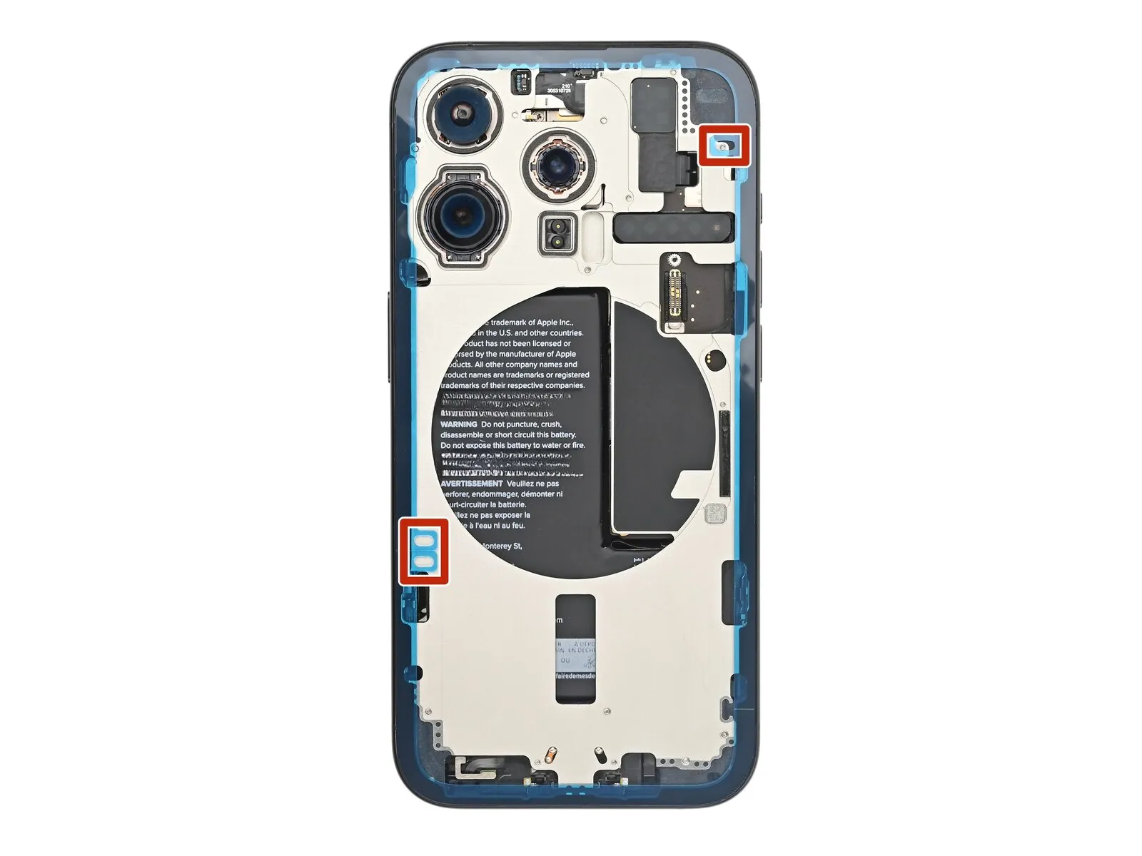
- After the uppermost protective layer is detached, observe three slender liners situated above the adhesive, each featuring a pull tab positioned close to the lower boundary.
- The location of these pull tabs might vary depending on the specific product.
- Should these pull tabs be absent, it’s possible the delicate liners were inadvertently peeled away during the prior procedure; exercise caution to prevent contact with the now-uncovered adhesive surface.
Step 32 | Align the back glass
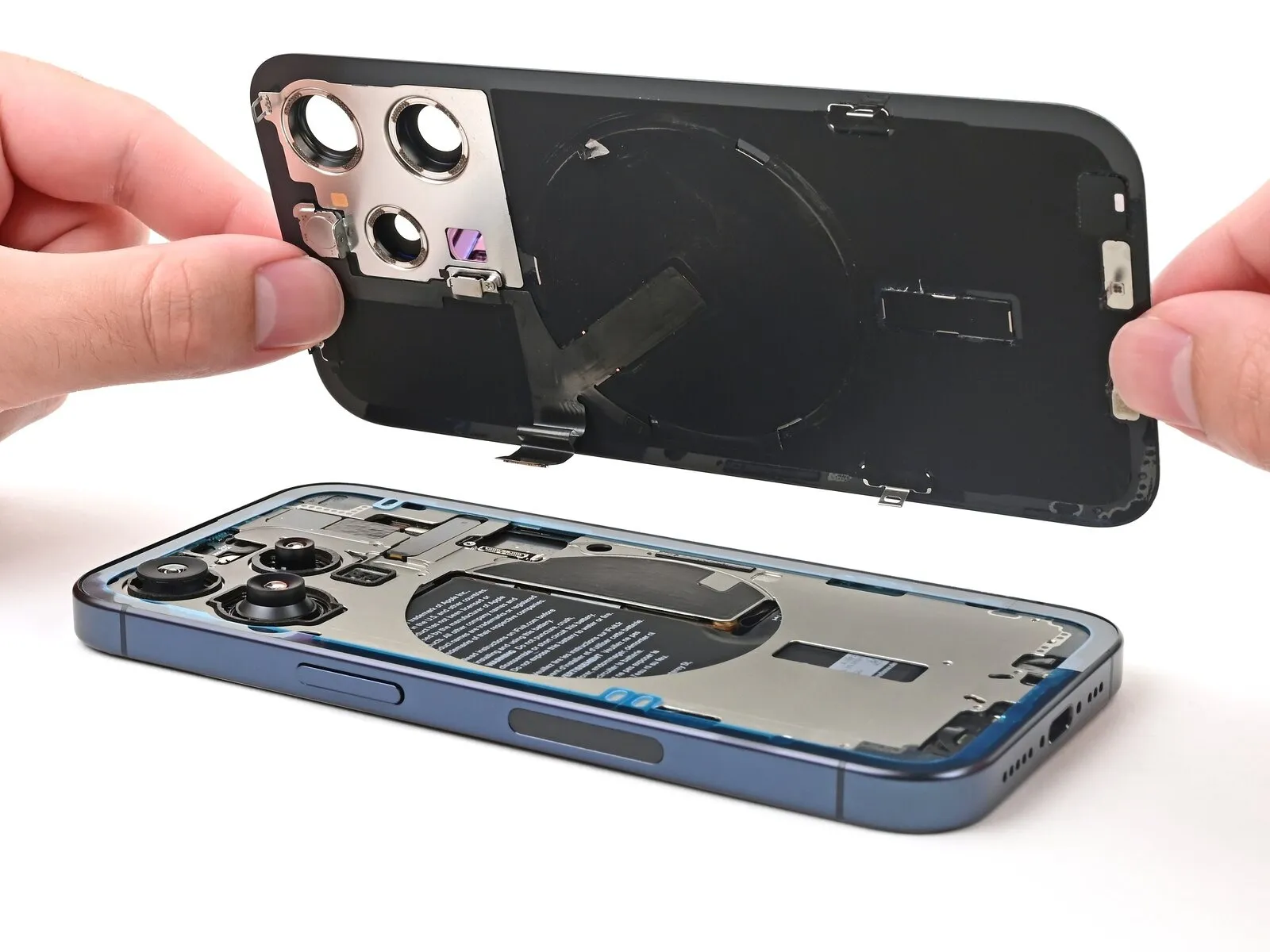

Step 33 | Connect the back glass


Step 34 | Install the wireless charging connector cover
- Employing tweezers, carefully maneuver the tab situated on the wireless charging connector cover to engage with its corresponding slot on the circuit board, ensuring proper alignment and seating.
- A specialized tri-point Y000 screwdriver is necessary for the subsequent installation step.The screw, precisely measuring 1.0 millimeters in length, must be utilized.This diminutive screw serves the critical purpose of fastening the wireless charging connector cover.Secure the wireless charging connector cover by carefully threading the 1.0 mm screw into its designated receptacle.To properly affix the wireless charging connector cover, employ a tri-point Y000 driver to tighten the 1.0 mm screw.
Step 35 | Remove the final adhesive liners
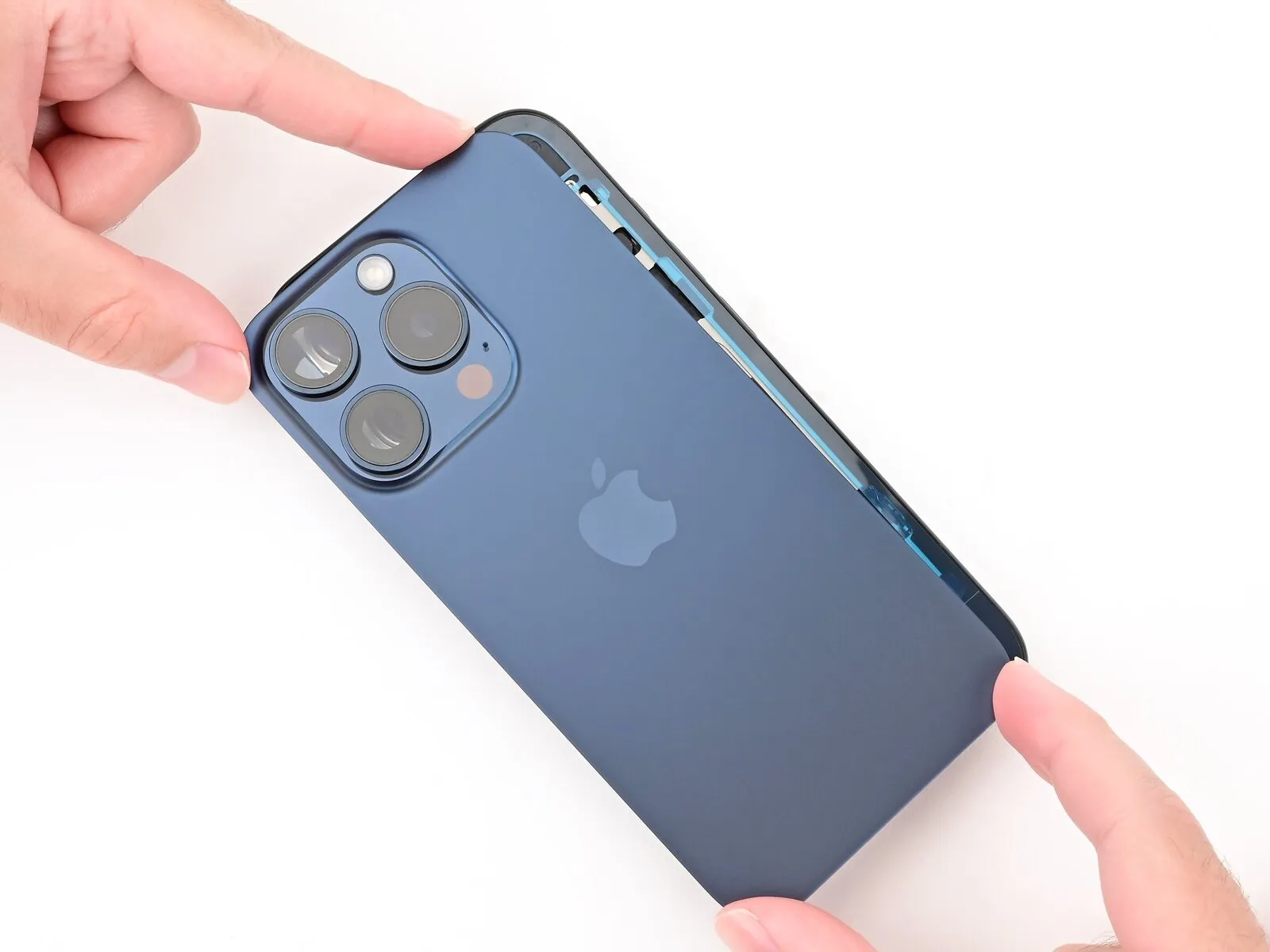


- Position the rear glass component above the device to permit access to the slim covering layer protecting the adhesive situated along the right-hand side of the frame.
- Employ tweezers to detach the narrow protective covering from the right edge.
Step 36
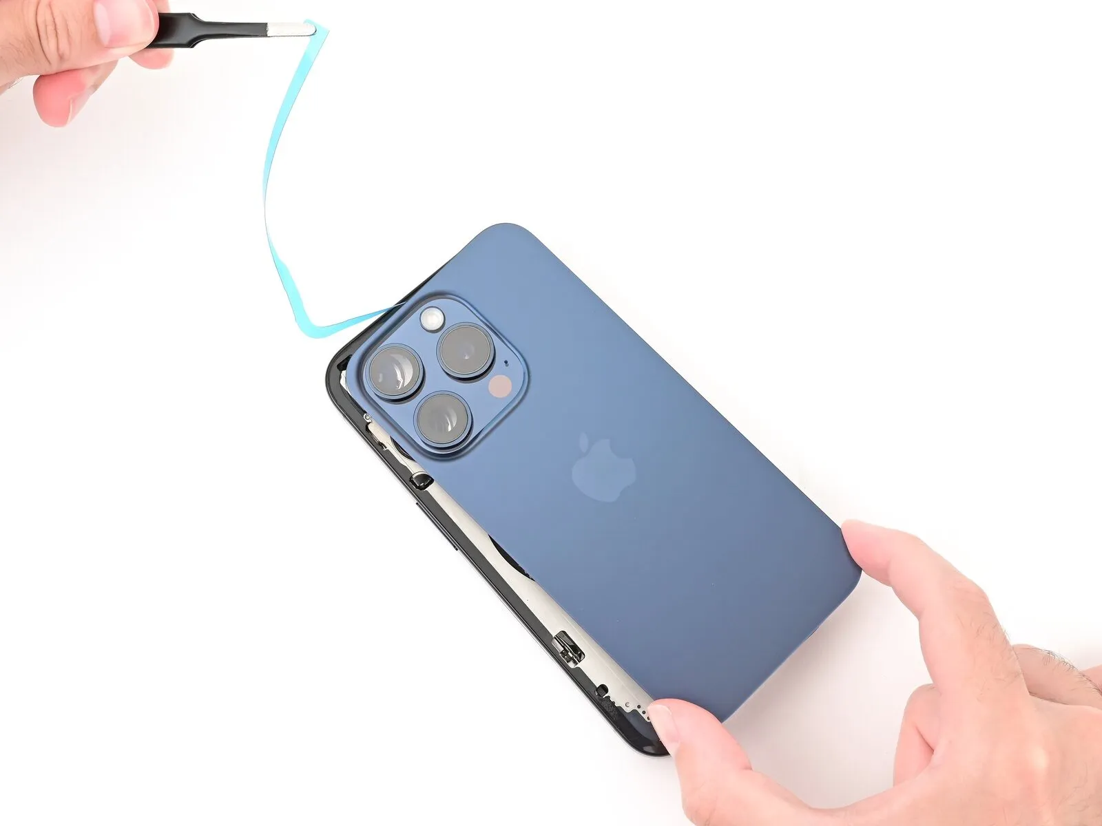

- Completely clear the residual, thin adhesive strips securing the rear glass by removing them.
Step 37 | Install the back glass



- Carefully position the rear glass component onto the device frame, ensuring proper alignment, and apply firm pressure to secure it.
Step 38
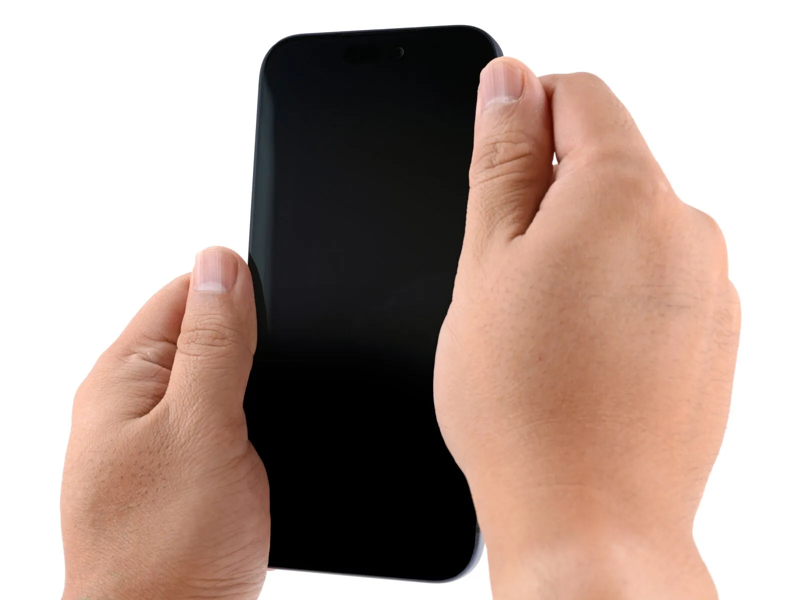
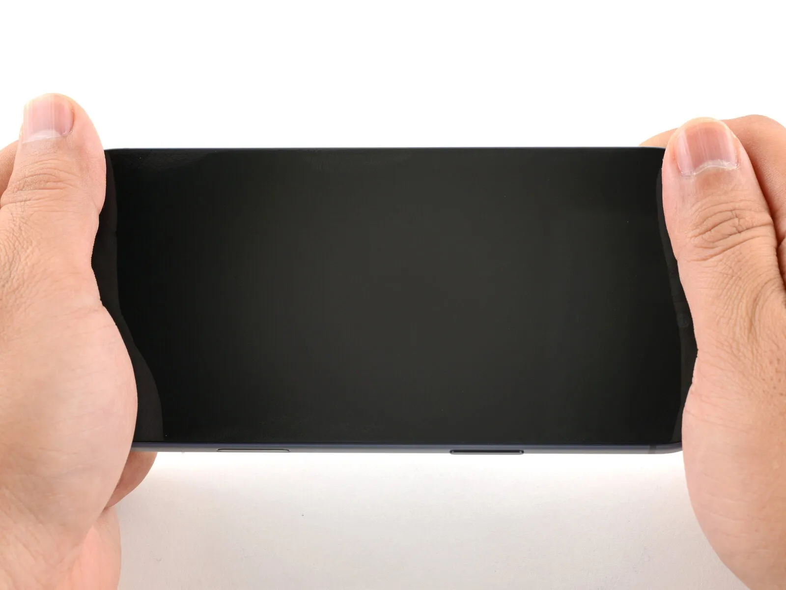
- Applying consistent, substantial pressure to the phone's perimeter will secure the adhesive bond and activate the retaining clips.
Step 39 | Install the pentalobe screws
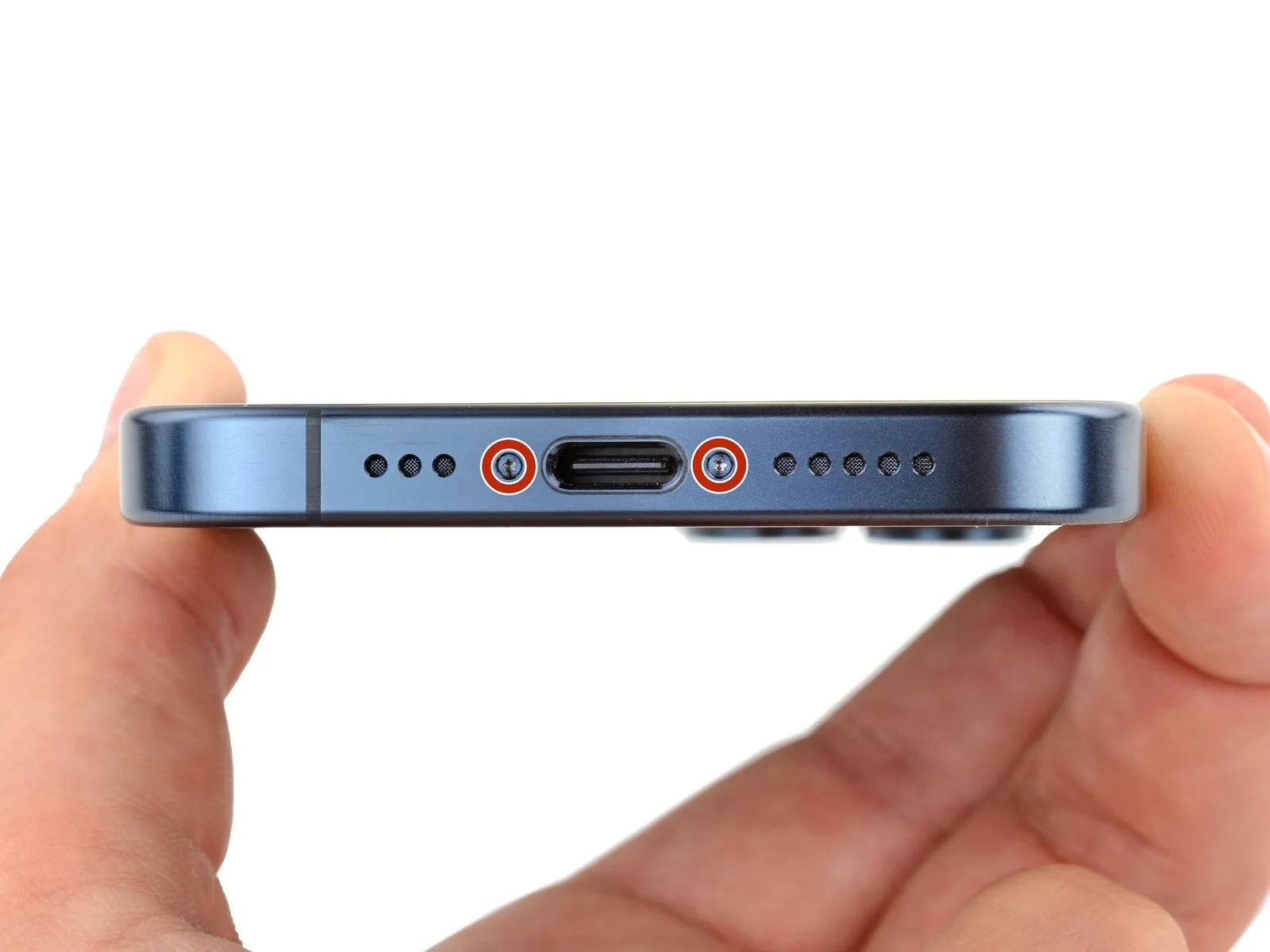
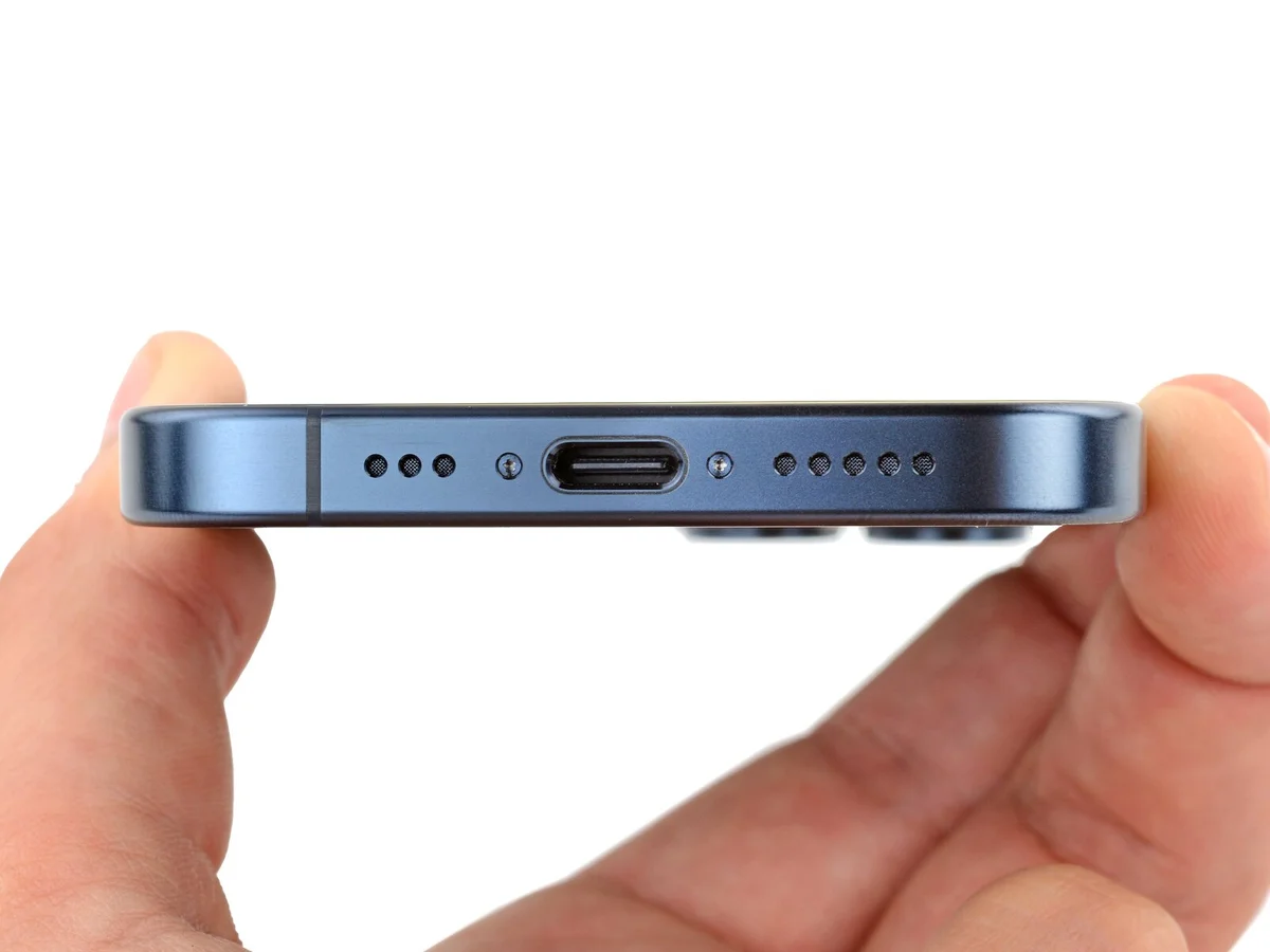
- Employ a P2 pentalobe screwdriver for the installation process.Two screws, each measuring 7 millimeters in length, require attachment.These fasteners are situated on both lateral aspects of the charging port.Securely fasten the screws to ensure proper component alignment.The P2 pentalobe screwdriver is essential for precise screw manipulation.
Step 40 | Heat the back glass


- Facilitate the adhesive's adherence by warming the perimeter of the rear glass with either a hairdryer or a heat gun, continuing until the surface feels warm to the hand.
Step 41 | Press the back glass

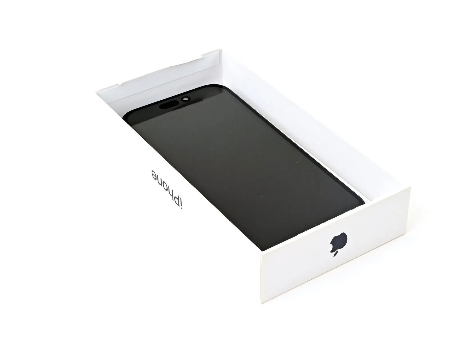
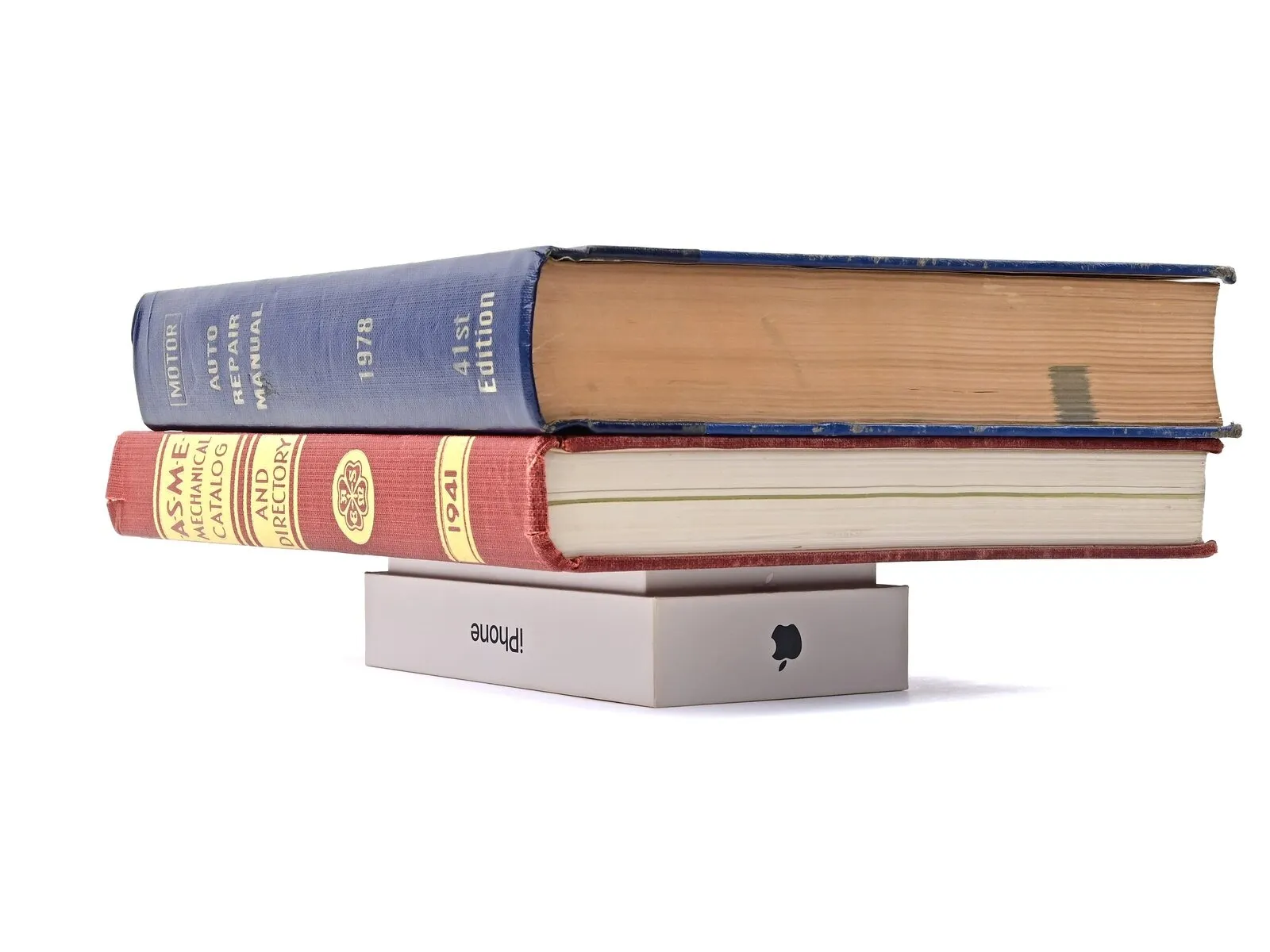
- Ensuring uniform pressure on the iPhone during reassembly is crucial for a secure screen-to-frame adhesion, necessitating consideration of the camera module's protrusion.
- Locate the iPhone's original packaging and utilize the lid, positioning it on a level work area.
- Should the original packaging be unavailable, proceed to an alternative compression technique, bypassing this procedure.
- Position the iPhone, with the display facing upward, within the box lid, aligning the camera bump with the corresponding indentation.
- Acquire an object approximating the iPhone's width but exceeding the box's sidewall height, and place it atop the iPhone, subsequently adding several substantial weights.
- Maintain the applied pressure for a minimum of thirty minutes, with overnight stabilization being the preferred duration for optimal bonding.
Step 42

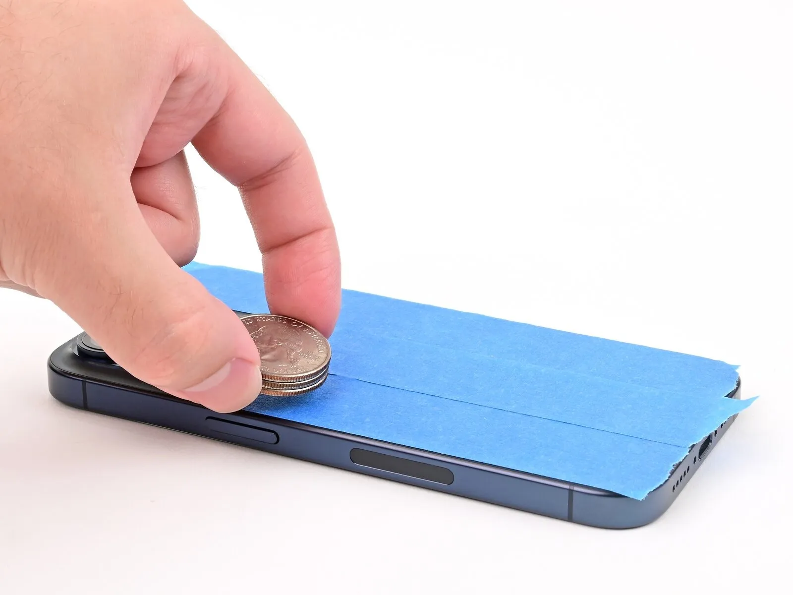

In the absence of the iPhone's initial packaging, an alternative technique for uniform screen compression involves the following procedure.
- Position the iPhone with its display facing downwards onto a cushioned, level surface.
- To safeguard the rear glass's coating, secure adhesive tape across its exterior.
- Along the perimeter of the rear glass, affix three coin layers, or comparable objects of equivalent thickness, onto the applied tape.
- Ensure a consistent distribution of these coins, maintaining a thickness equal to or exceeding the height of the camera module.
Step 43

To apply downward pressure, position several books or similarly weighted items atop your iPhone.
Because coins can create a lasting mark, avoid placing them on delicate or valuable surfaces during this process.
Maintain the applied pressure for a minimum of thirty minutes; an extended duration, such as overnight, is preferable for optimal results.