iPhone 15 Pro Rear Cameras Replacement
Use this guide to replace the rear cameras in your iPhone 15 Pro.
If your photos are coming out distorted or fuzzy, or your cameras aren't focusing or taking photos at all, it may be time to replace them.
- You'll need replacement screen adhesive to complete this repair.
Note: Due to Apple's parts pairing restrictions, on iOS 17.6 and earlier, you may receive warnings regarding replacement rear cameras, but they'll still function normally. On iOS 18 and newer, you can pair the replacement camera module using Apple's Repair Assistant.
Step 1 | Prepare your iPhone for disassembly

- Unplug all cables from your phone.
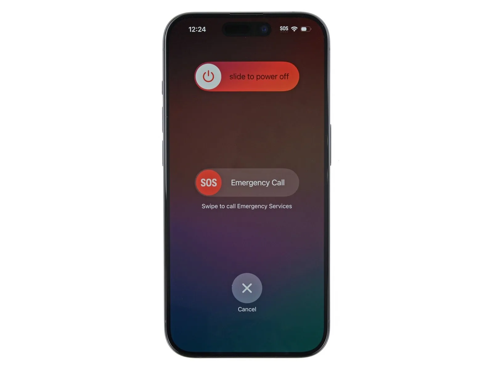
- Hold the power and either volume button and slide to power off your phone.
Step 2 | Tape over any cracks
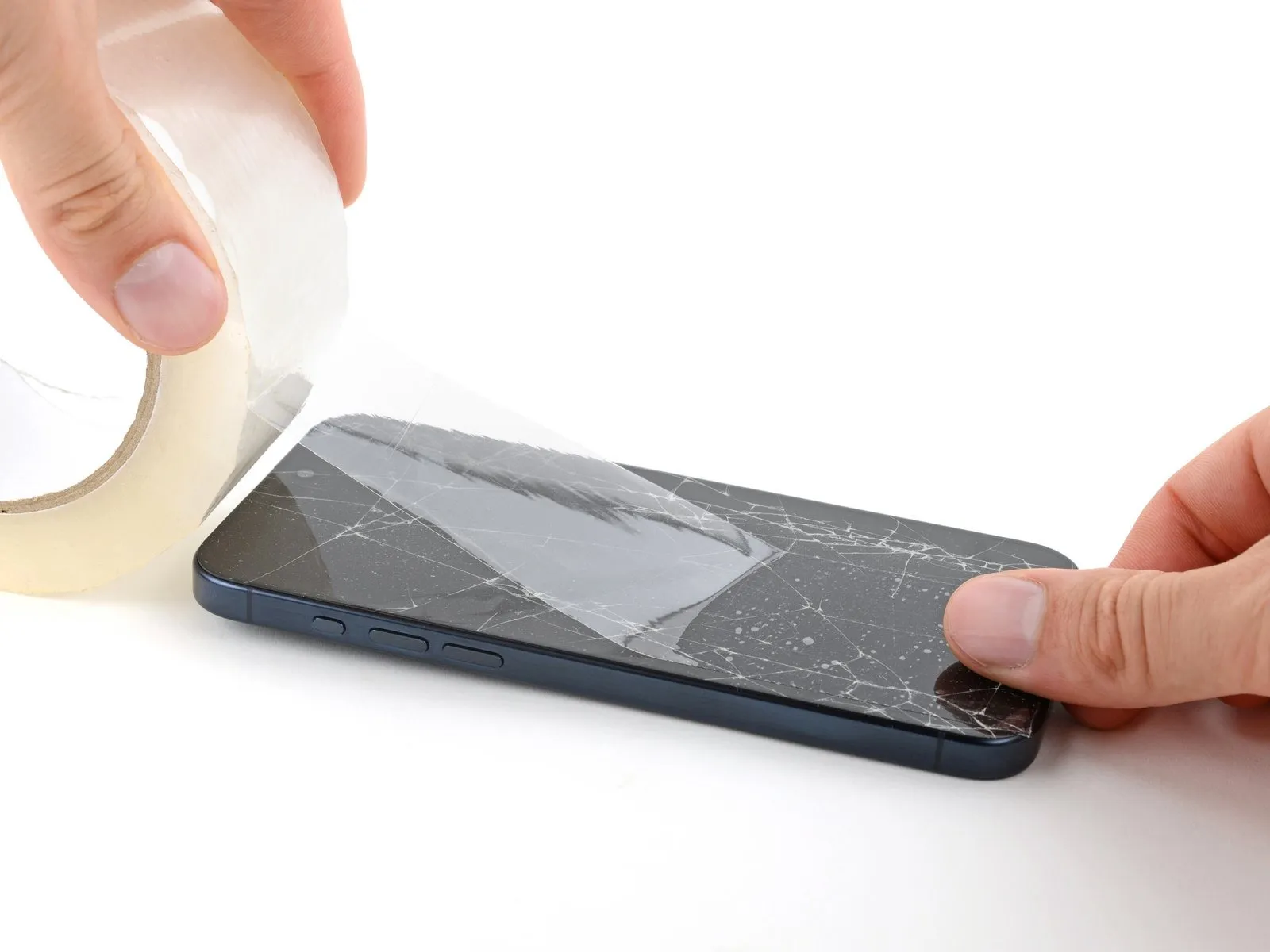
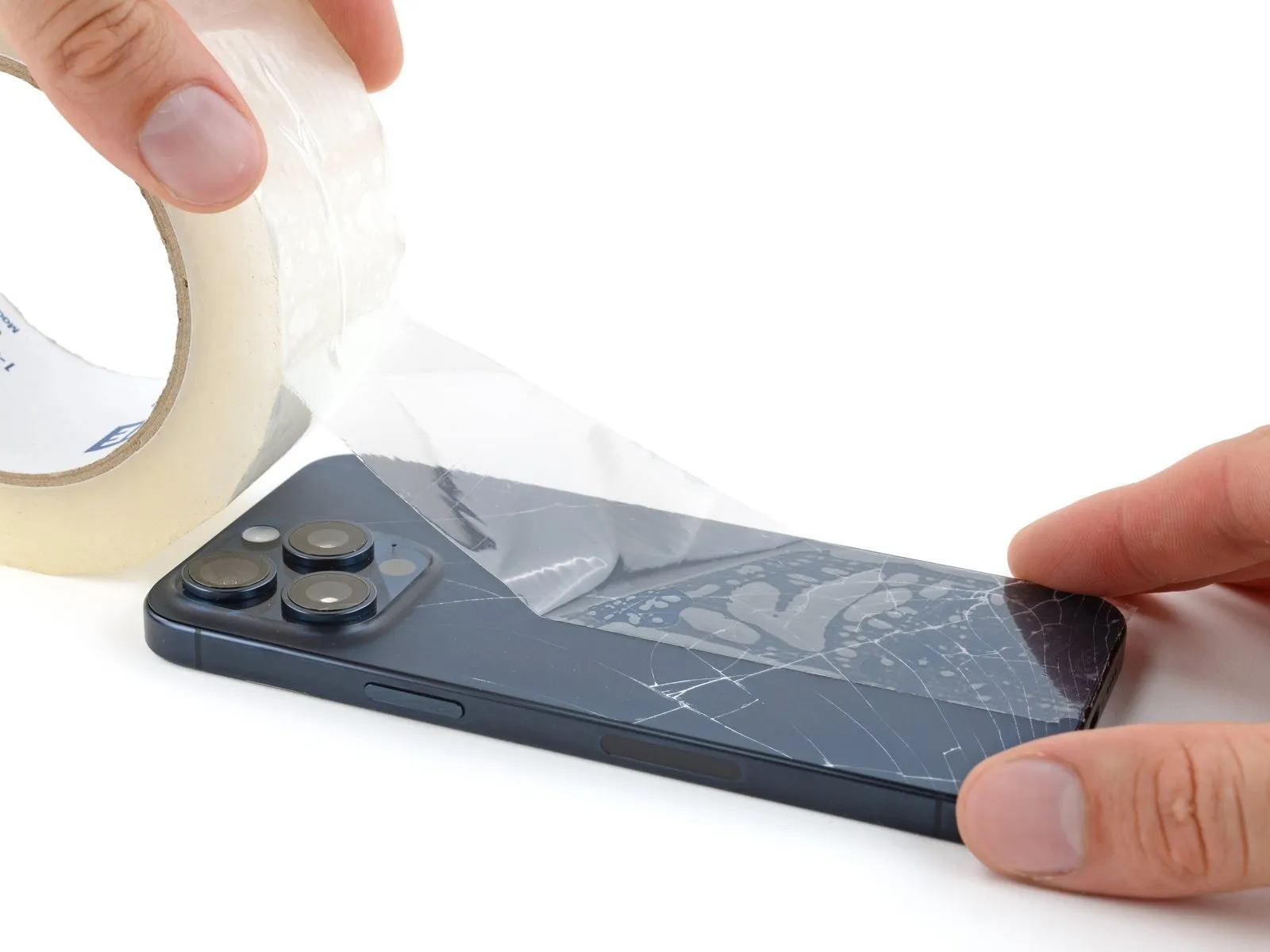
- Make sure there's a smooth area near the bottom edge that's big enough for a suction cup to stick to.
Step 3 | Mark your opening picks


- Measure 3 mm from the tip and mark the opening pick with a permanent marker.
- You can also mark the other corners of the pick with different measurements.
- Alternatively, tape a coin to a pick 3 mm from the tip.
Step 4 | Remove the pentalobe screws

Step 5 | Heat the bottom edge
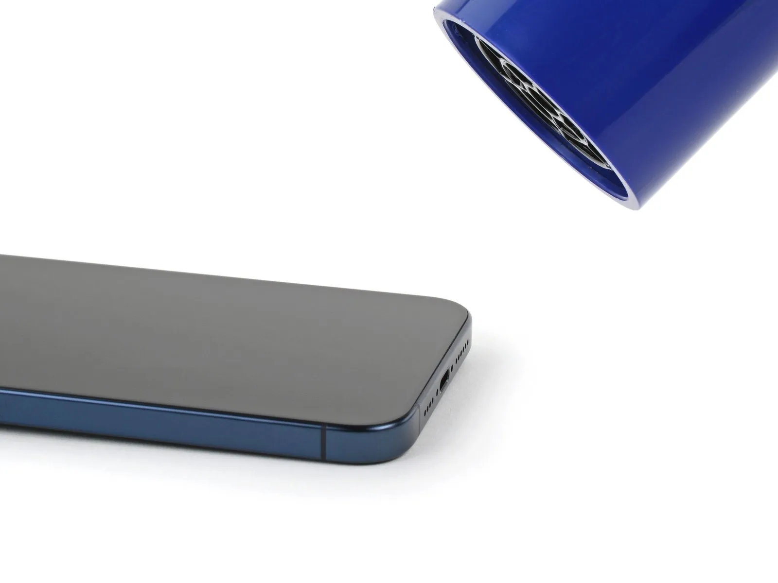
- Be careful not to heat the phone hotter than this-the battery is susceptible to heat damage.
Step 6 | Insert an opening pick
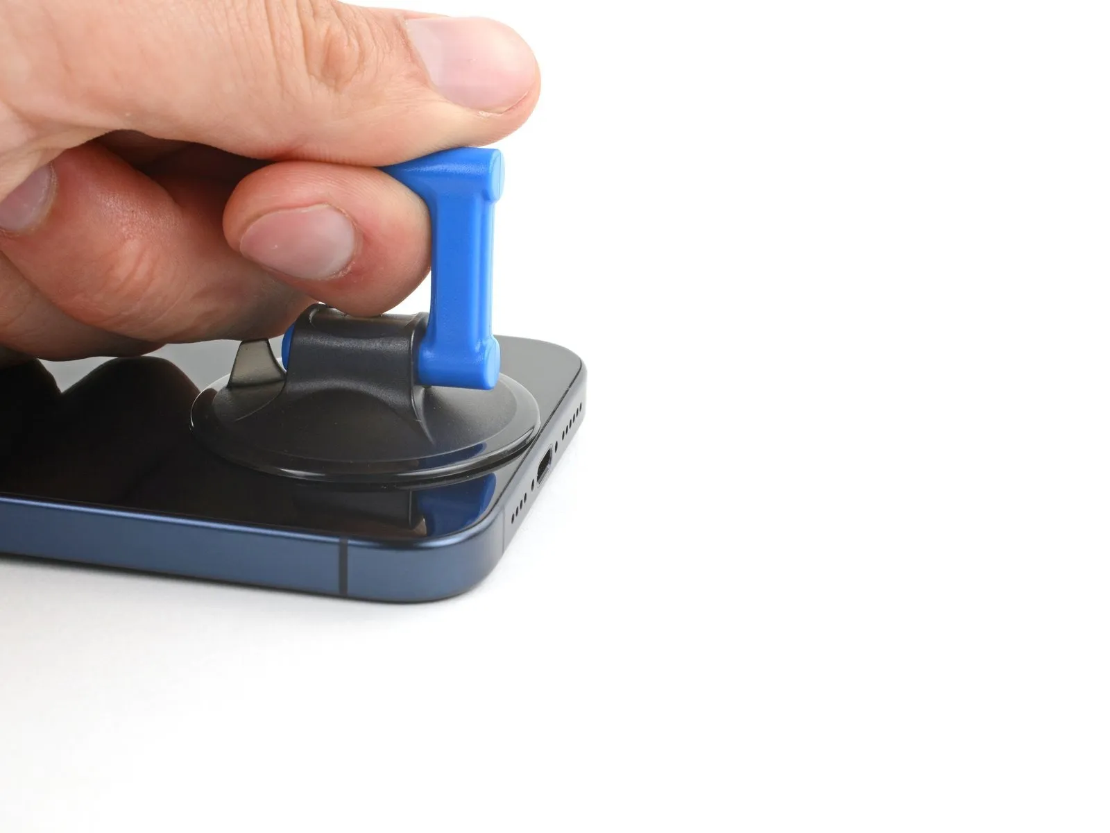
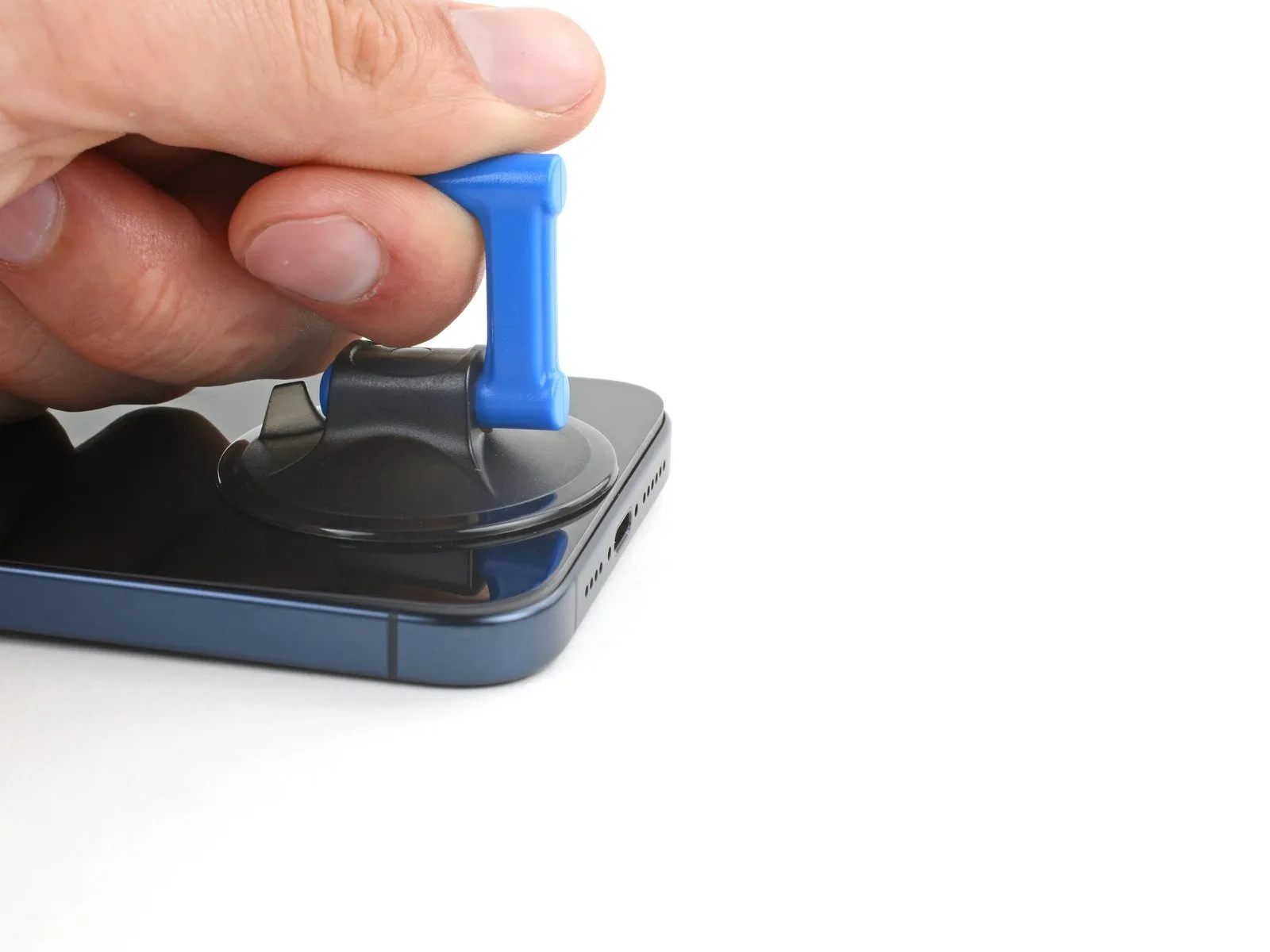
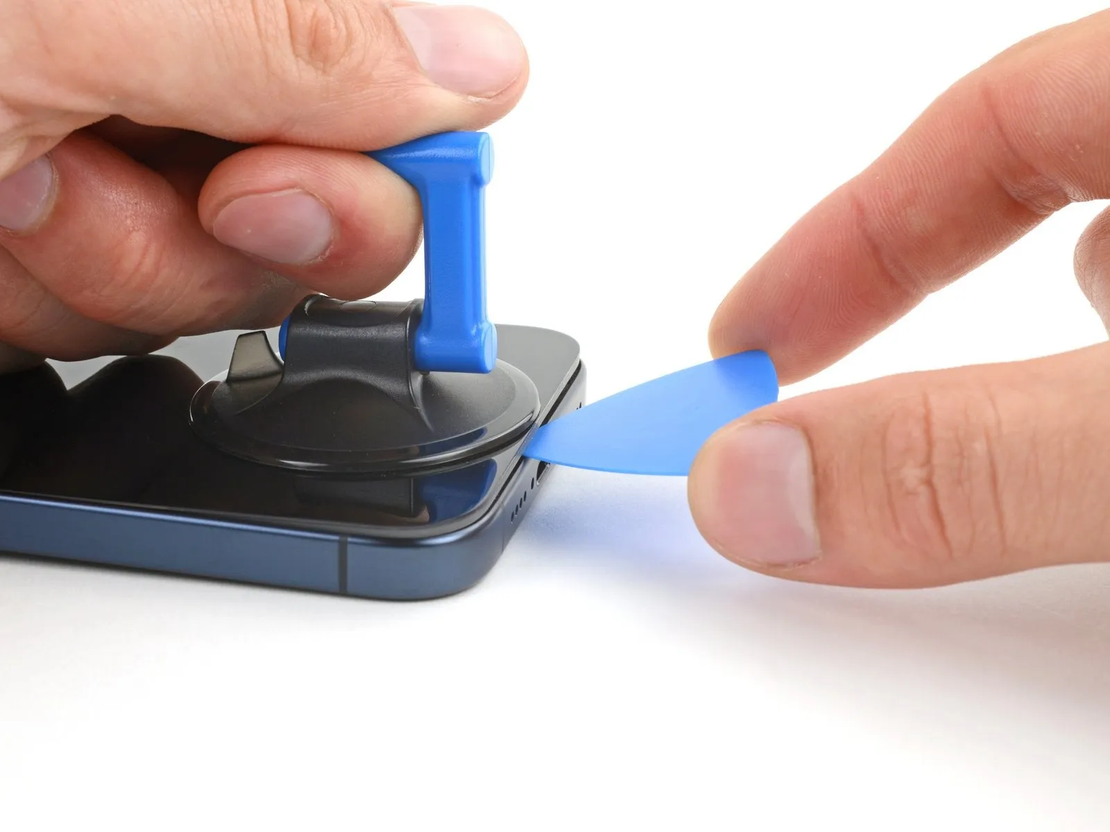
- Apply a suction handle to the bottom edge of the screen.
- Pull up on the handle with a strong, steady force to create a gap between the screen and the frame.
- Insert the tip of an opening pick into the gap.
Step 7 | Screen information

As you slice the adhesive securing the screen in the next steps, be careful of the following areas:
- There are two delicate cables connecting the screen to the phone: one just above the action button, and the other near the middle of the left edge.
- There are multiple spring contacts around the perimeter of the phone. Be extra careful not to insert your pick deeper than suggested in these locations to avoid bending the contacts.
Step 8 | Separate the bottom edge adhesive


- Don't insert your opening pick deeper than 3 mm along the bottom edge.
- Slide your pick back and forth along the bottom edge to separate the adhesive.
- Leave your pick inserted in the bottom right corner to prevent the adhesive from re-sealing.
Step 9 | Heat the right edge
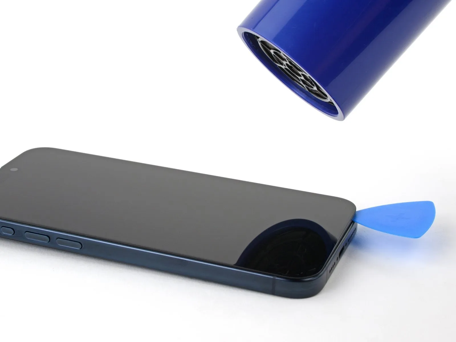
Heat the right edge of the screen until it's hot to the touch.
Step 10 | Position the opening pick
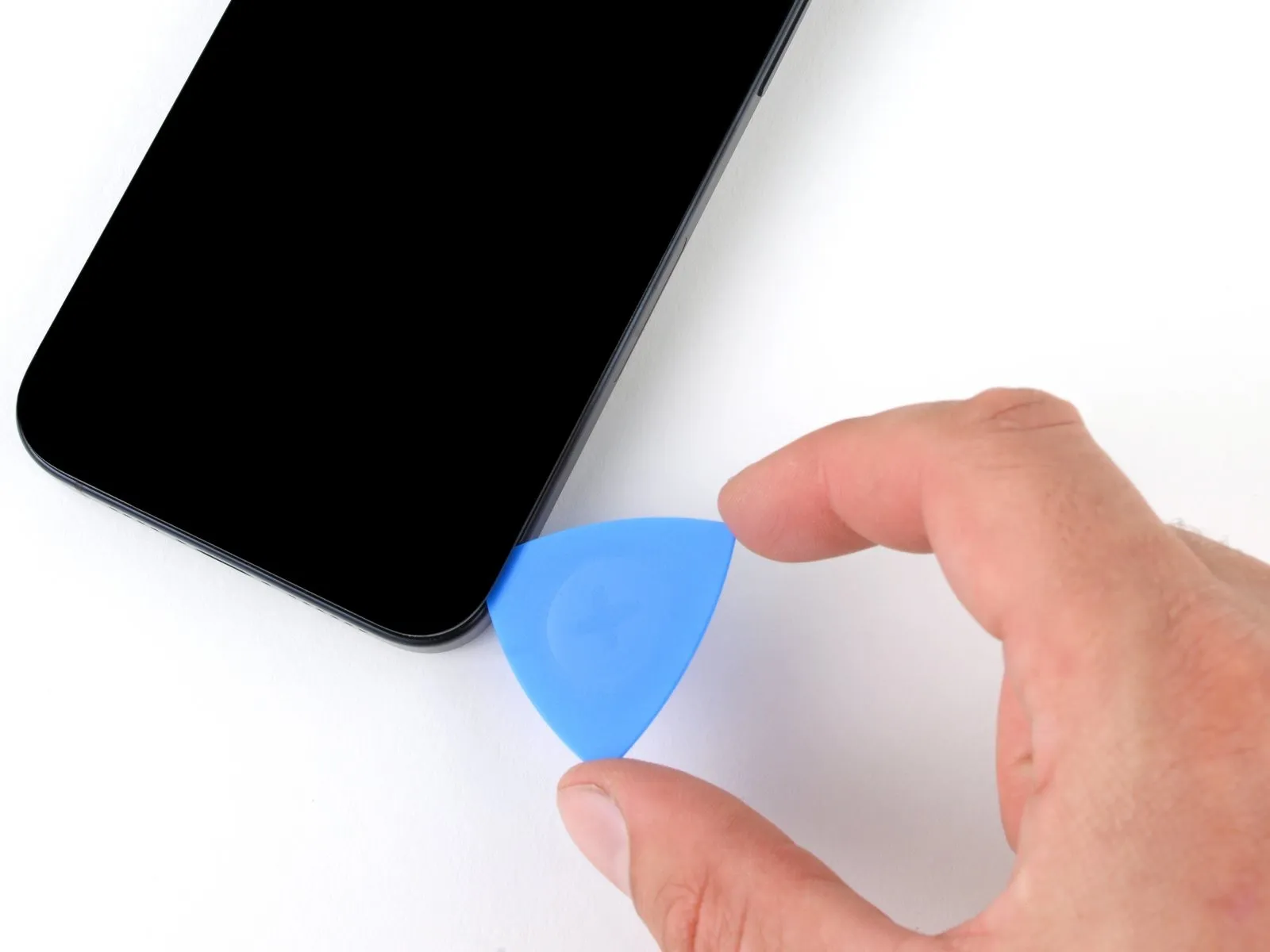
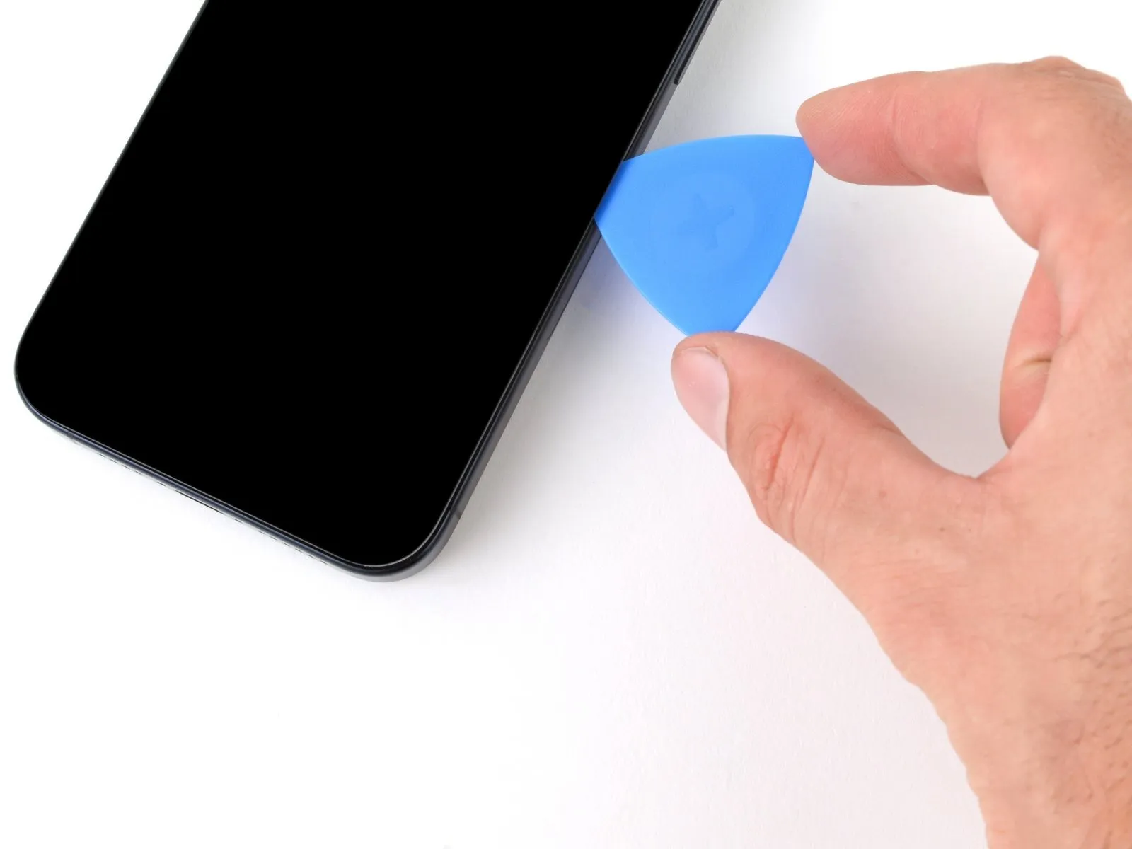
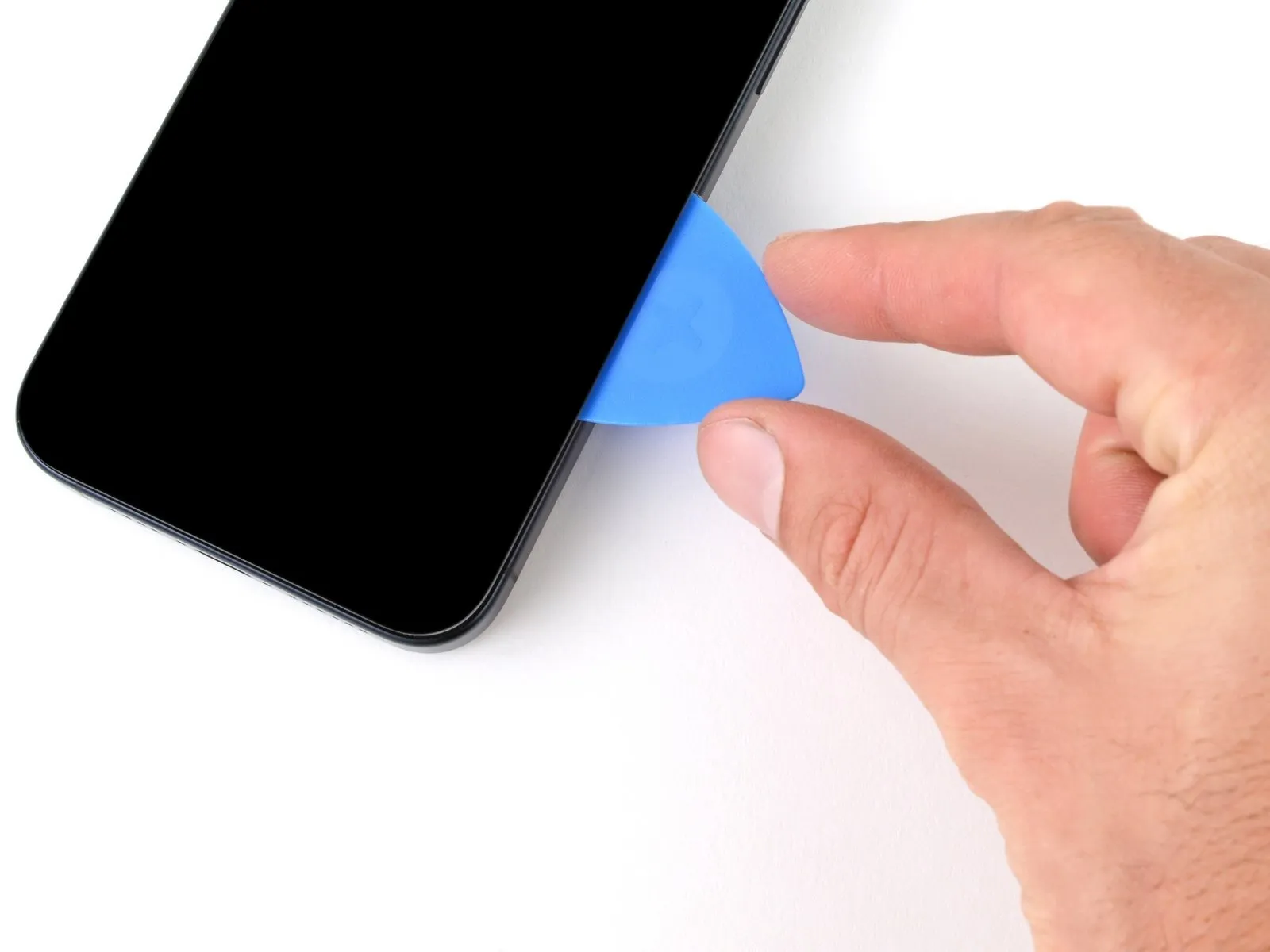
- Don't insert your pick deeper than 5 mm along the right edge.
- Slide your pick around the bottom right corner of the screen and toward the power button until you feel a hard stop at a clip securing the screen.
- Rotate your pick so the flat edge is under the screen.
Step 11 | Release the right clip
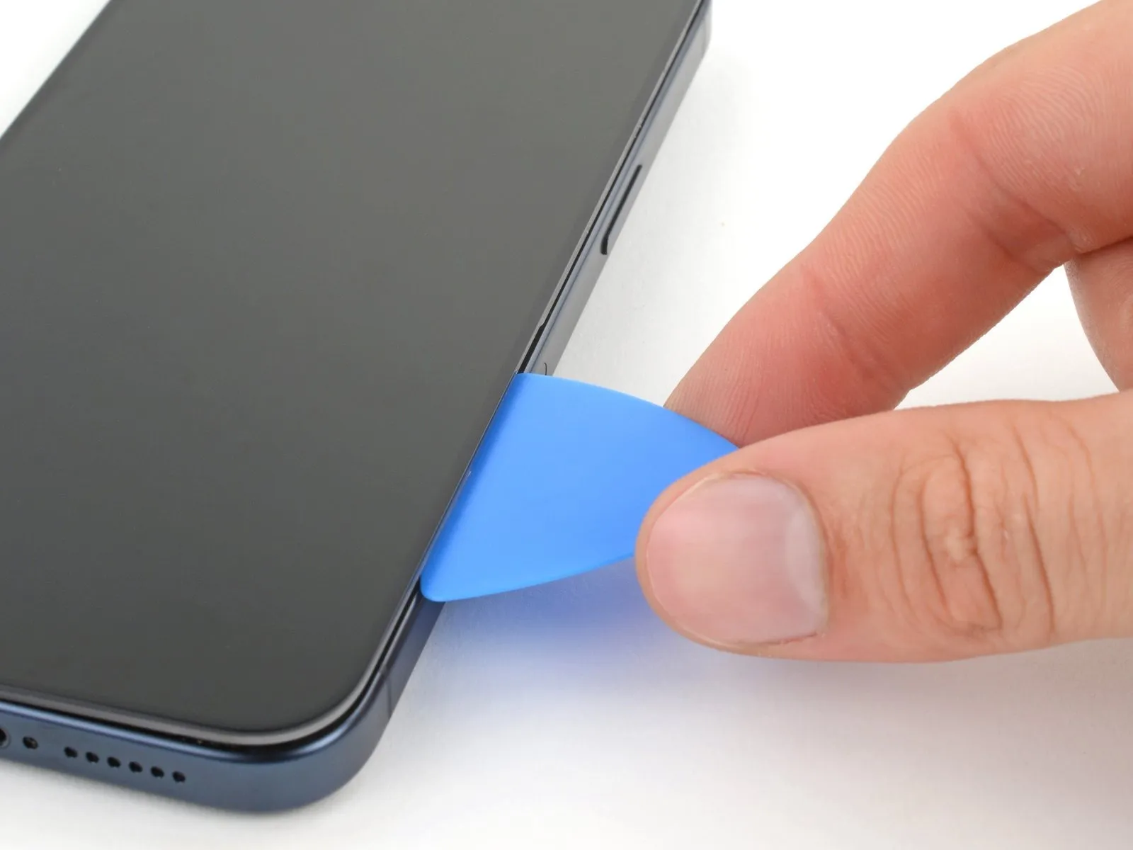
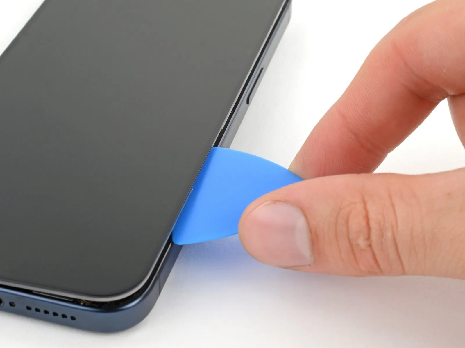
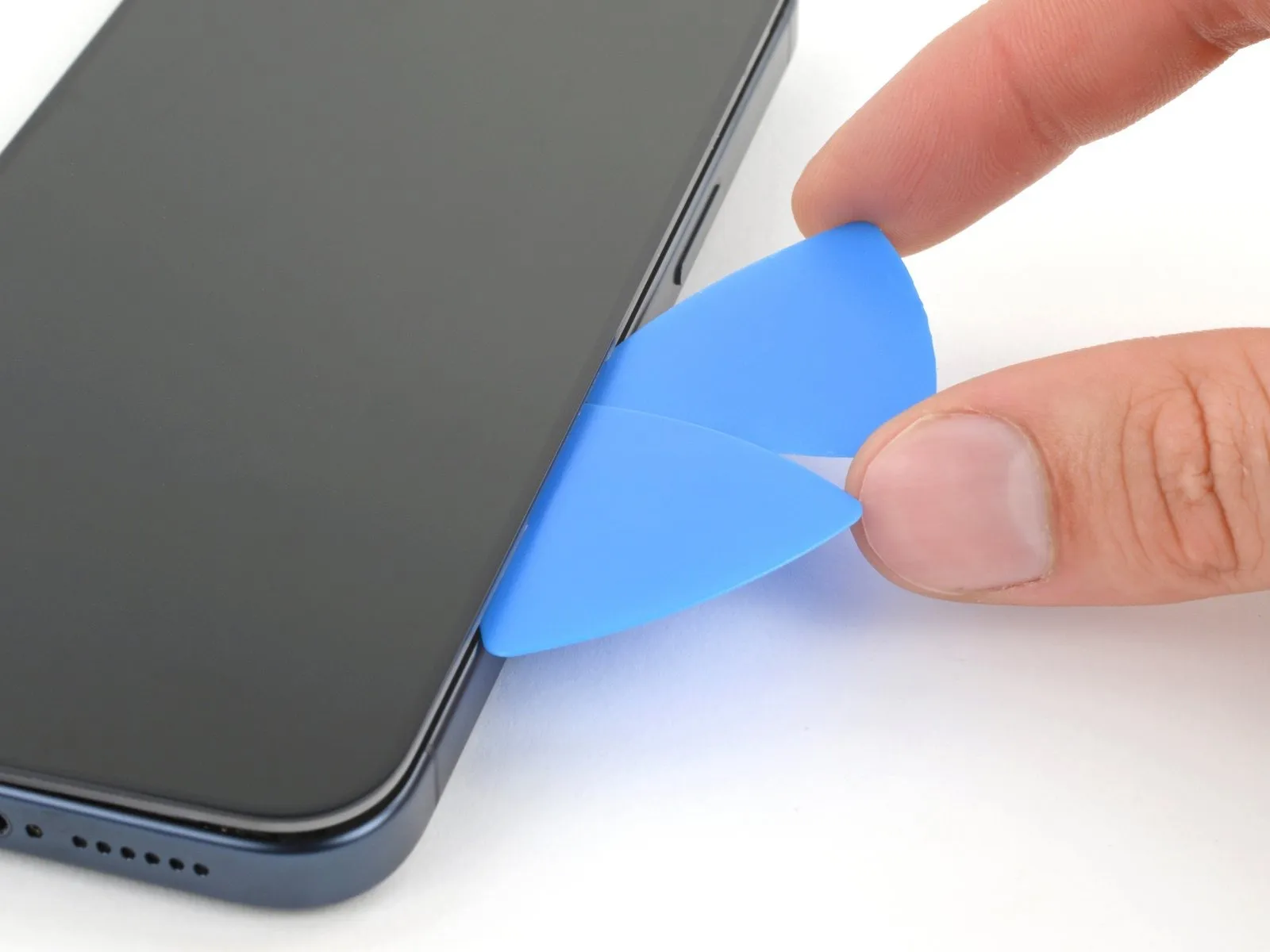
Twist the pick to increase the gap between the screen and the frame until the right clip releases.
Insert a second opening pick to the right of the first pick.
Step 12 | Separate the right edge adhesive
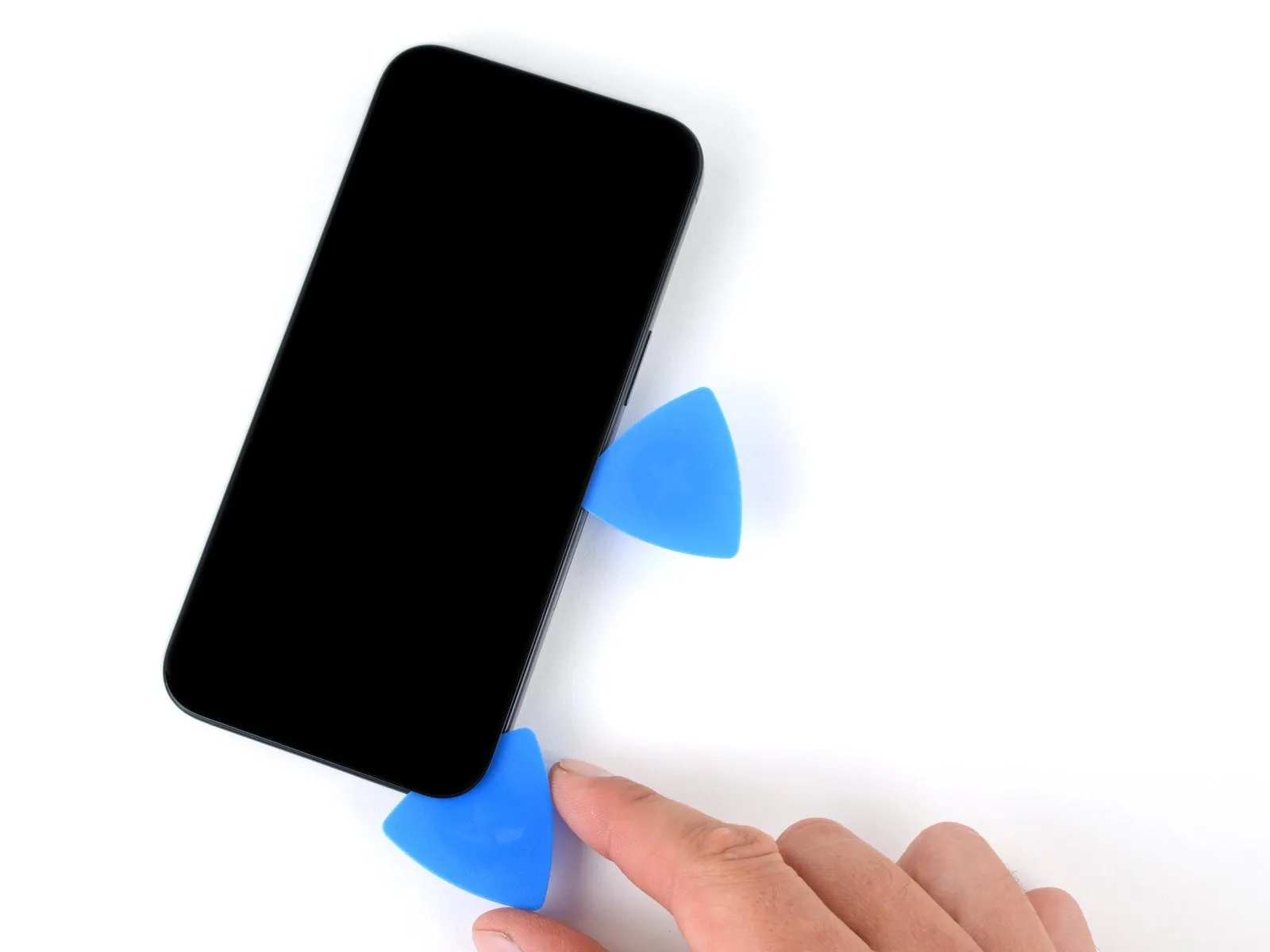
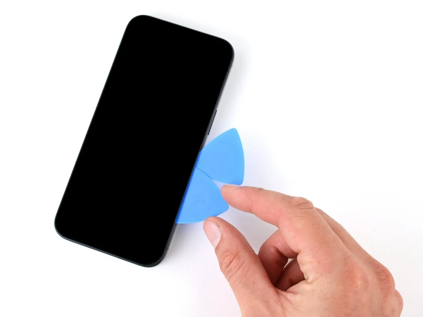
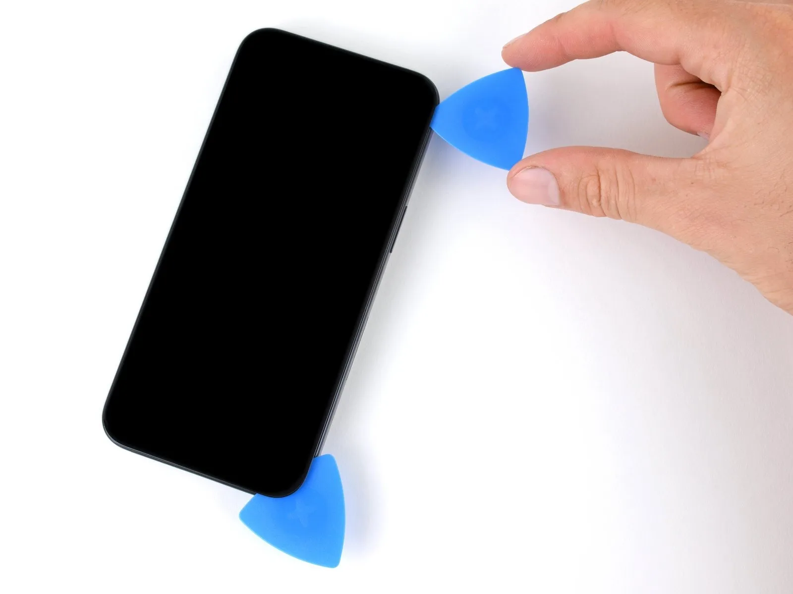
Slide the first pick back to the bottom right corner of the screen.
Slide the second pick to the top right corner of the screen to separate the adhesive.
Leave these picks inserted to prevent the adhesive from resealing.
Step 13 | Heat the top edge
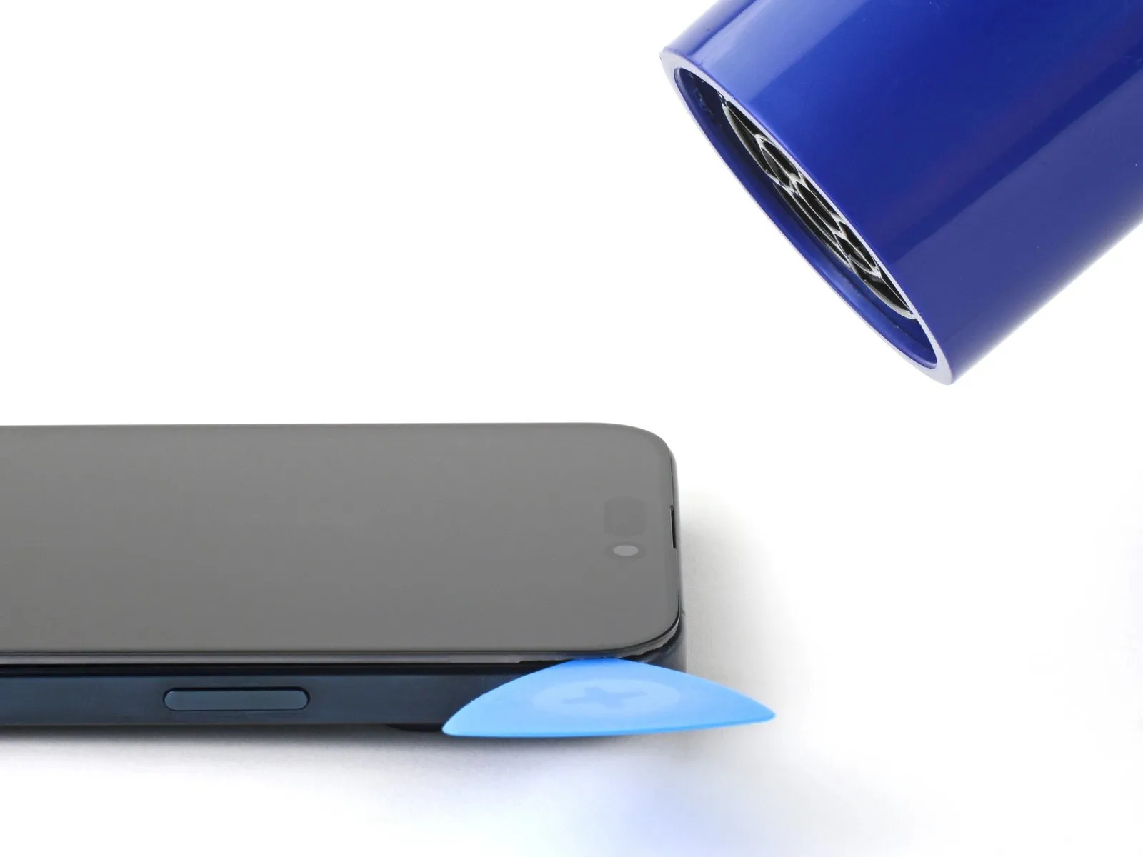
Heat the top edge of the screen until it's hot to the touch.
Step 14 | Separate the top edge adhesive


- Don't insert your pick deeper than 3 mm along the top edge.
- Slide your pick around the top right corner and along the top edge to release the two clips and adhesive securing it.
Step 15 | Heat the left edge

Heat the left edge of the screen until it's hot to the touch.
Step 16 | Separate the left edge adhesive

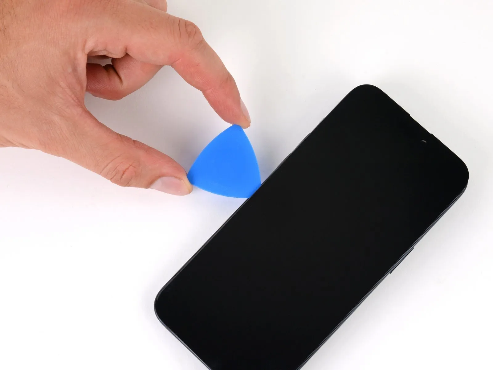

- Don't insert your pick deeper than 2 mm along the left edge to avoid the two cables connecting the screen to the phone.
- Rotate your pick around the top left corner of the screen.
- Slide your pick to the bottom left corner of the screen to separate the adhesive.
Step 17 | Prop up the screen

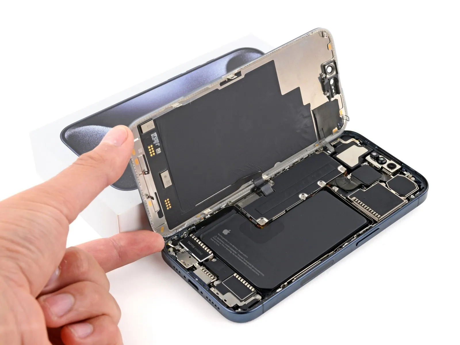
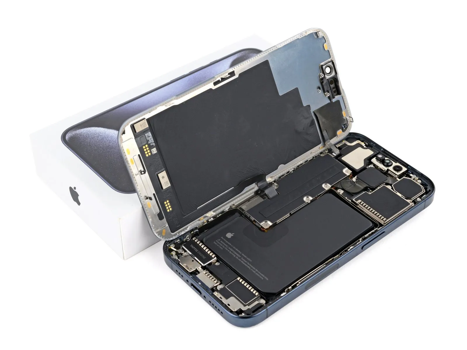
- Place a small box or stack of books to the left of your phone so you can prop up the screen while disconnecting its cables.
- Swing up the right edge of the screen like the front cover of a book.
- If the screen feels stuck, go back around the perimeter with an opening pick to separate any remaining adhesive.
- Prop up the screen so you can access its cables without straining them.
Step 18 | Unfasten the logic board cover

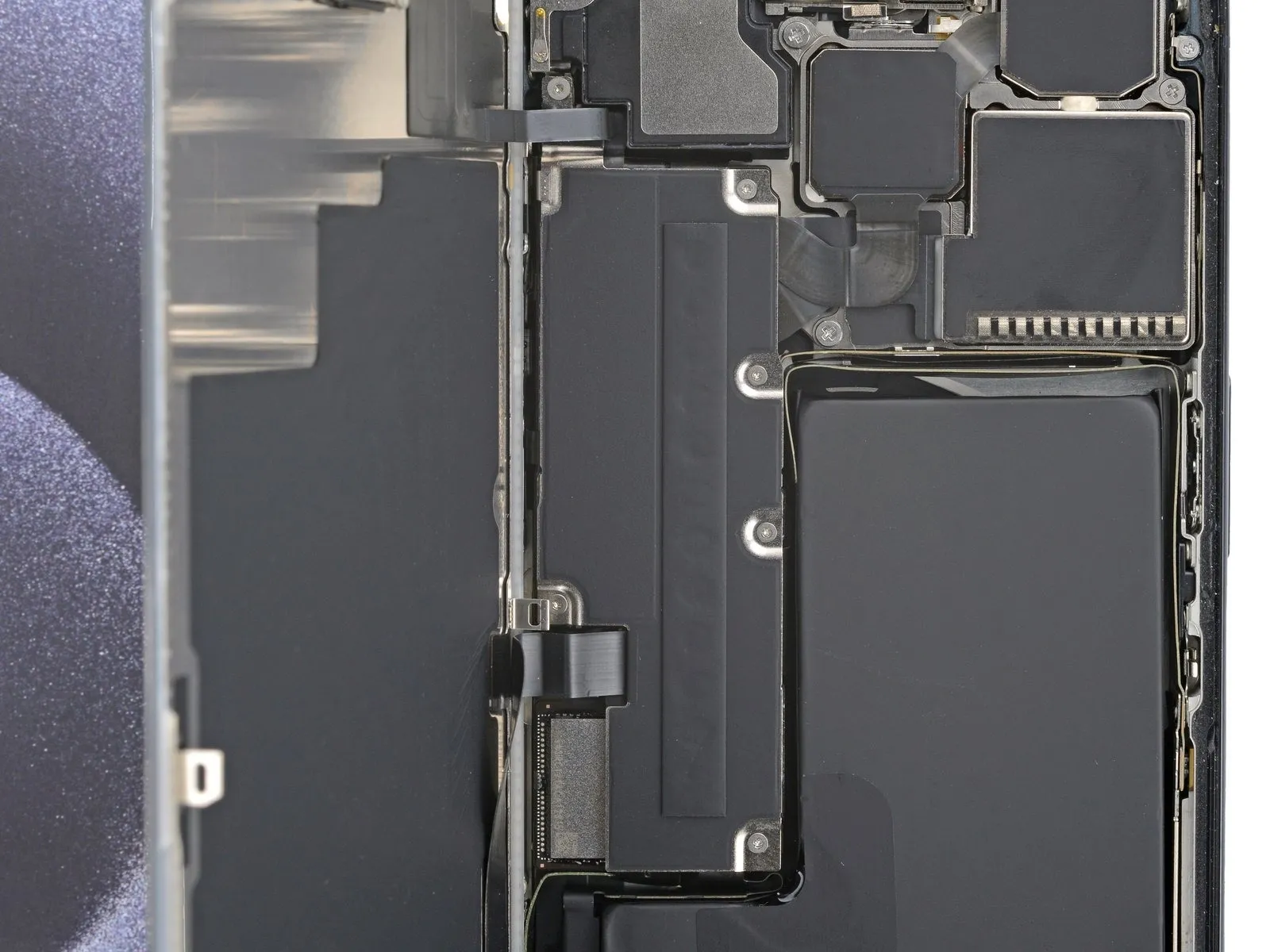
- Use a Y000 screwdriver to remove the six screws securing the logic board cover:
- Four 1.6 mm-long screws
- Two 1.3 mm-long screws
Step 19 | Remove the logic board cover

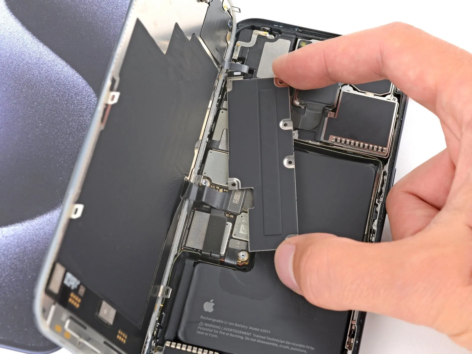
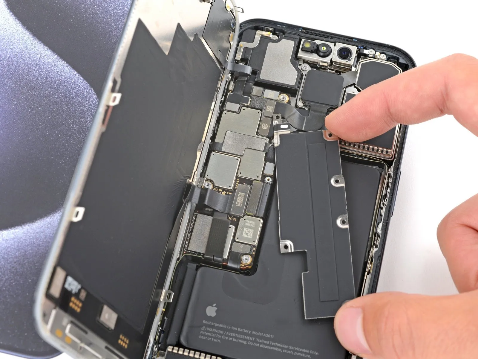
- Rotate the bottom of the logic board cover counterclockwise and slide the top left corner out from under the ambient light sensor cable to remove it.
During reassembly, make sure the top left corner of the cover goes under the ambient light sensor cable.
Step 20 | Disconnect the battery

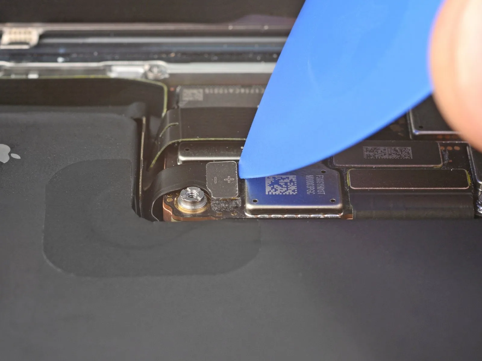
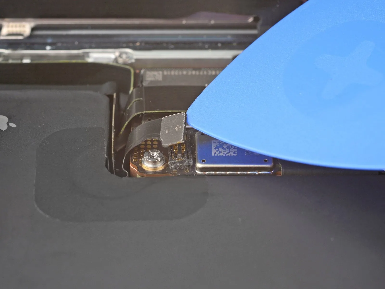
- Use the tip of an opening pick to pry up and disconnect the battery press connector from the bottom right corner of the logic board.
To reconnect a press connector, align it over its socket and gently press down on one side until it clicks into place, then press down on the other side. Make sure it sits flat, as the insulating rubber around the sockets might prevent it from connecting fully.
Step 21 | Disconnect the screen
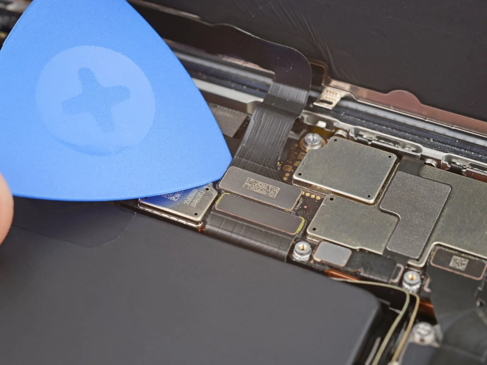
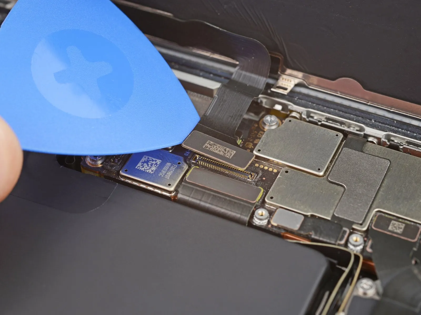
Step 22 | Disconnect the ambient light sensor
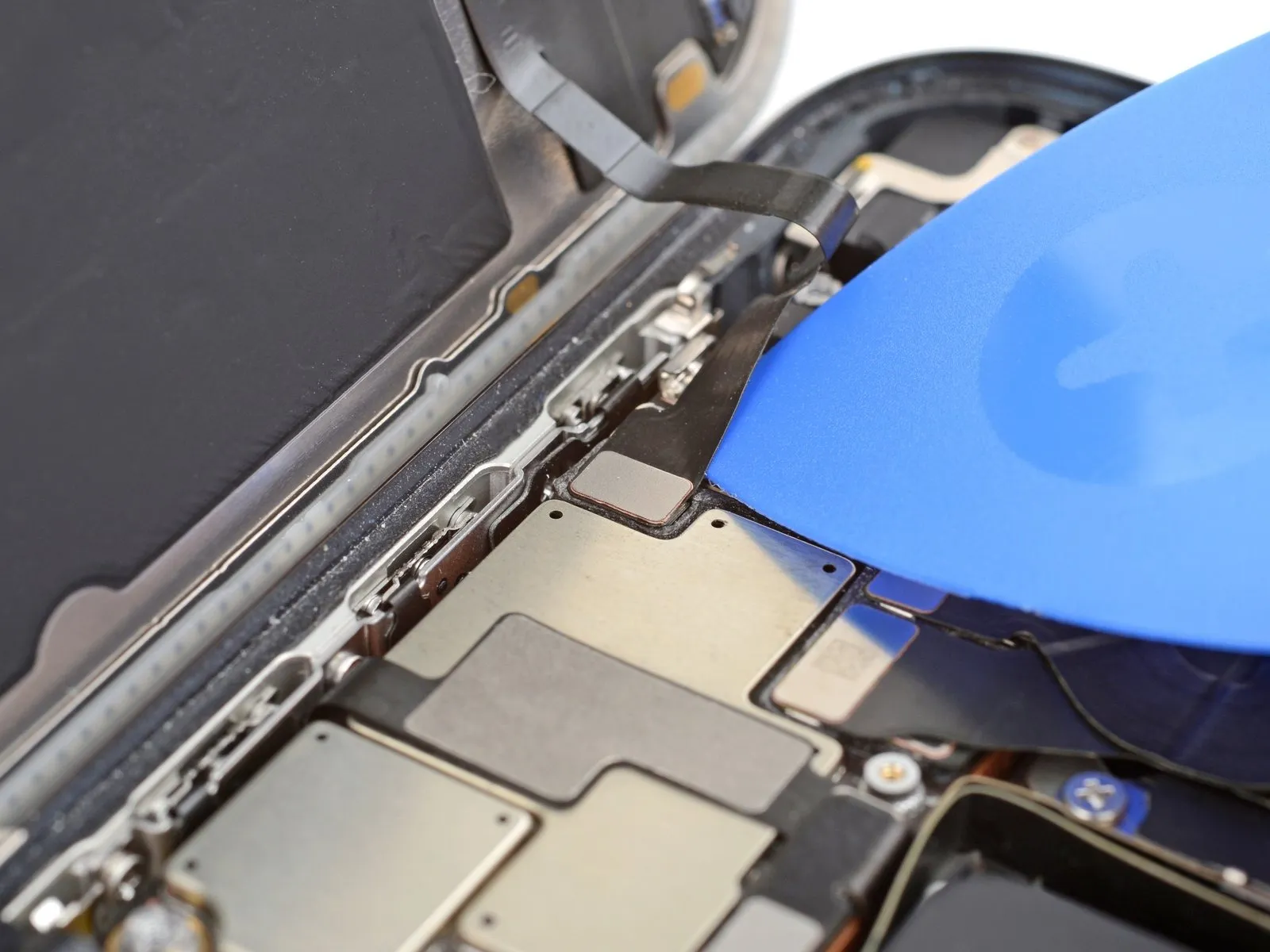
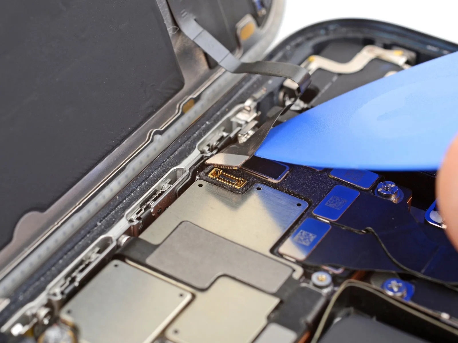
- Gently slide the tip of an opening pick under the ambient light sensor cable near the top left corner of the logic board.
- Lift the cable to disconnect it.
Step 23 | Remove the screen
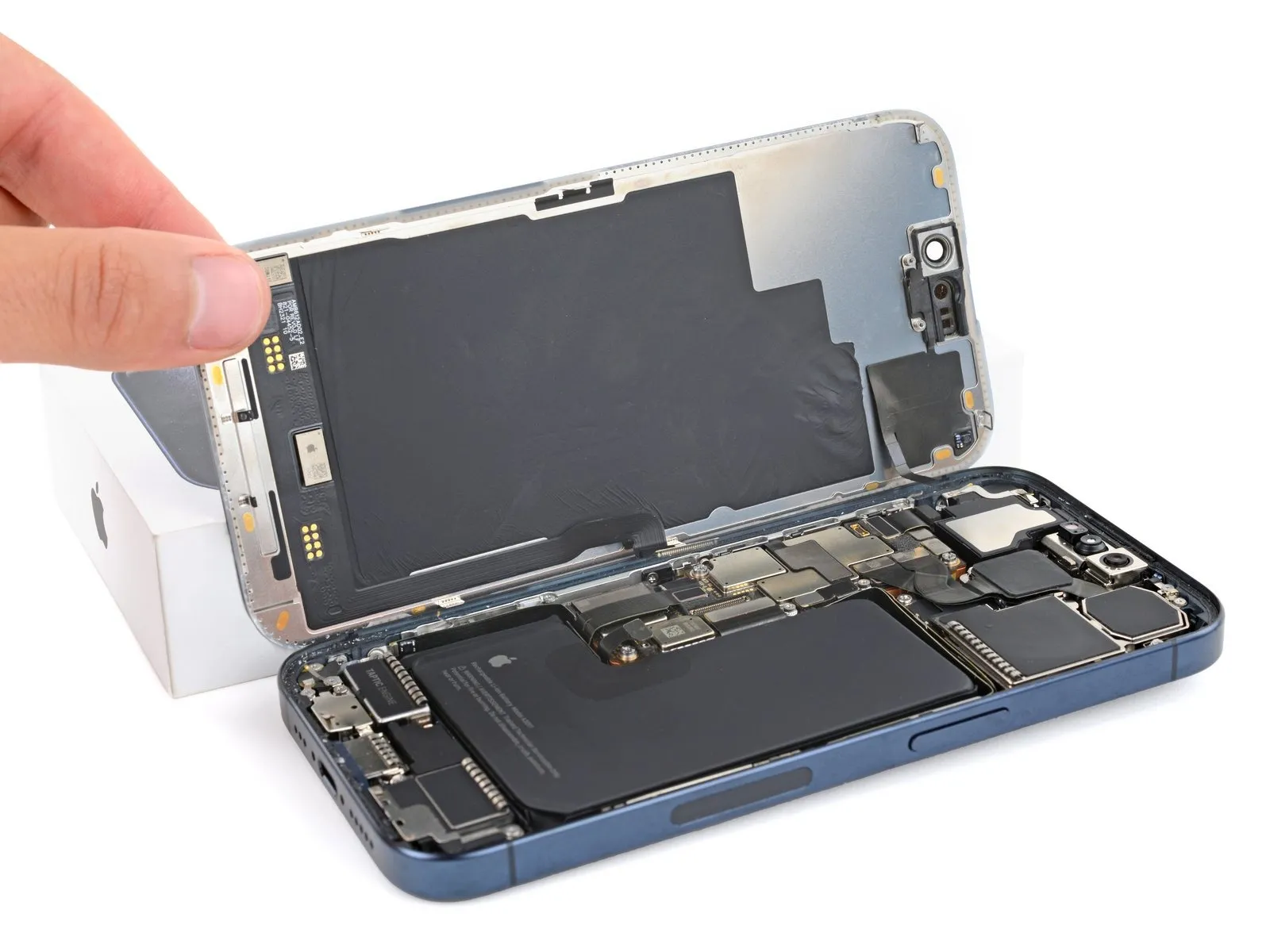
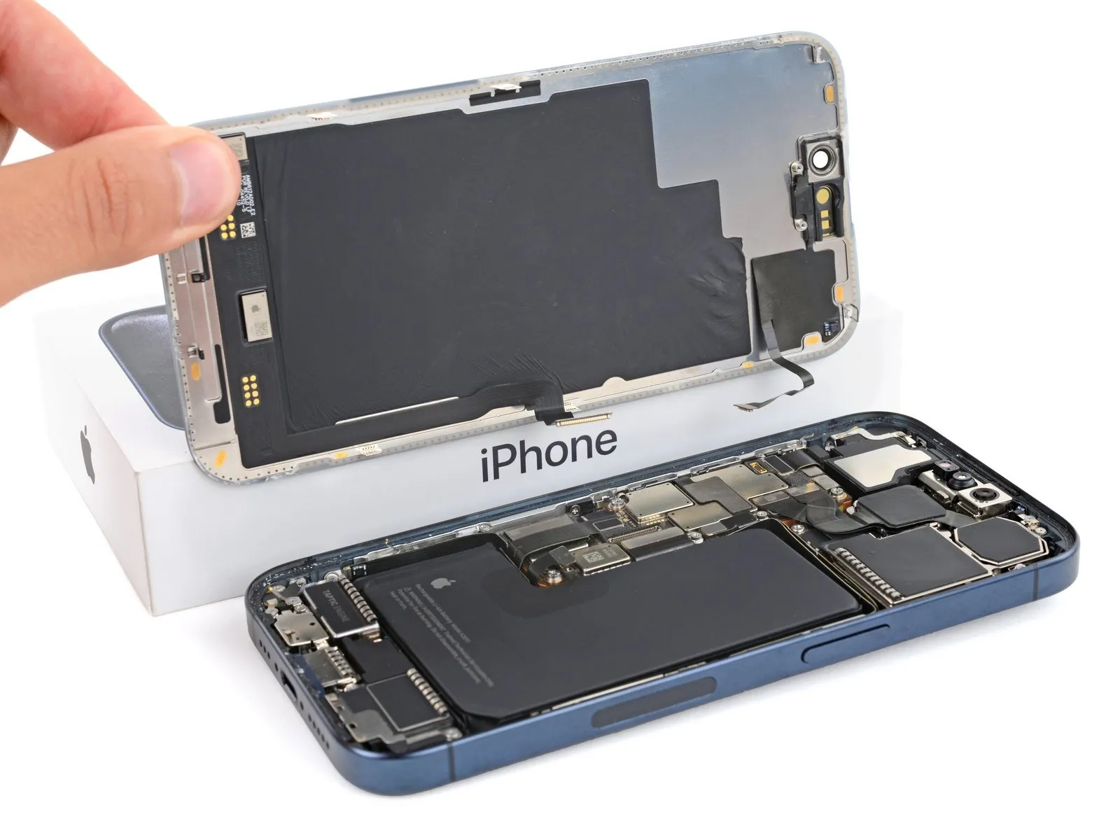
- Remove the screen.
- During reassembly, follow this guide to apply new adhesive and install your screen.
- Be careful not to damage any of the spring contacts as you clean the frame.
Step 24 | Disconnect the rear cameras
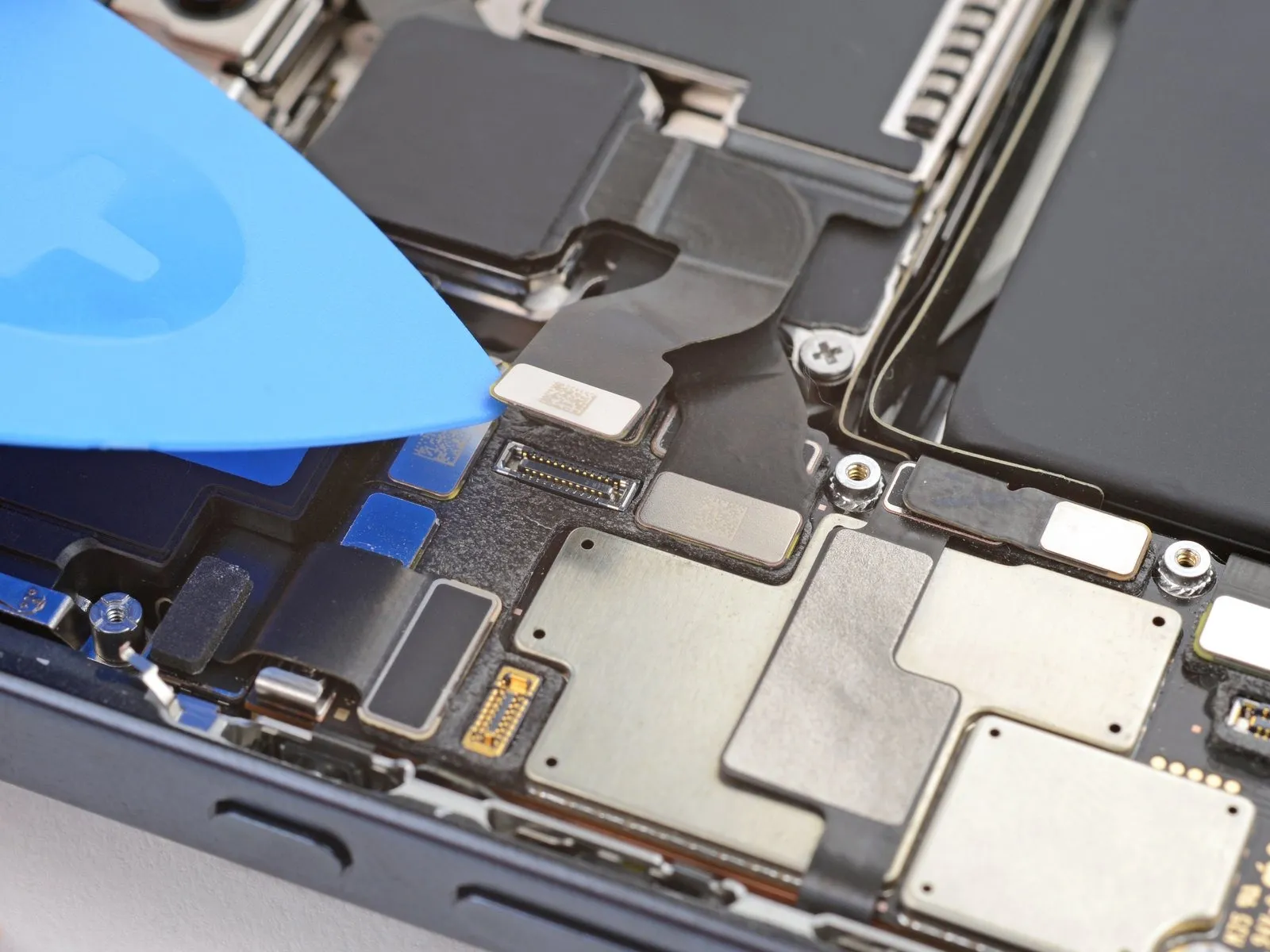


- Use the tip of an opening pick to pry up and disconnect the three rear camera press connectors from the top right of the logic board.
- The third connector is hidden beneath the top one-lift the top cable slightly to reveal the third connector.
Step 25 | Unfasten the rear cameras
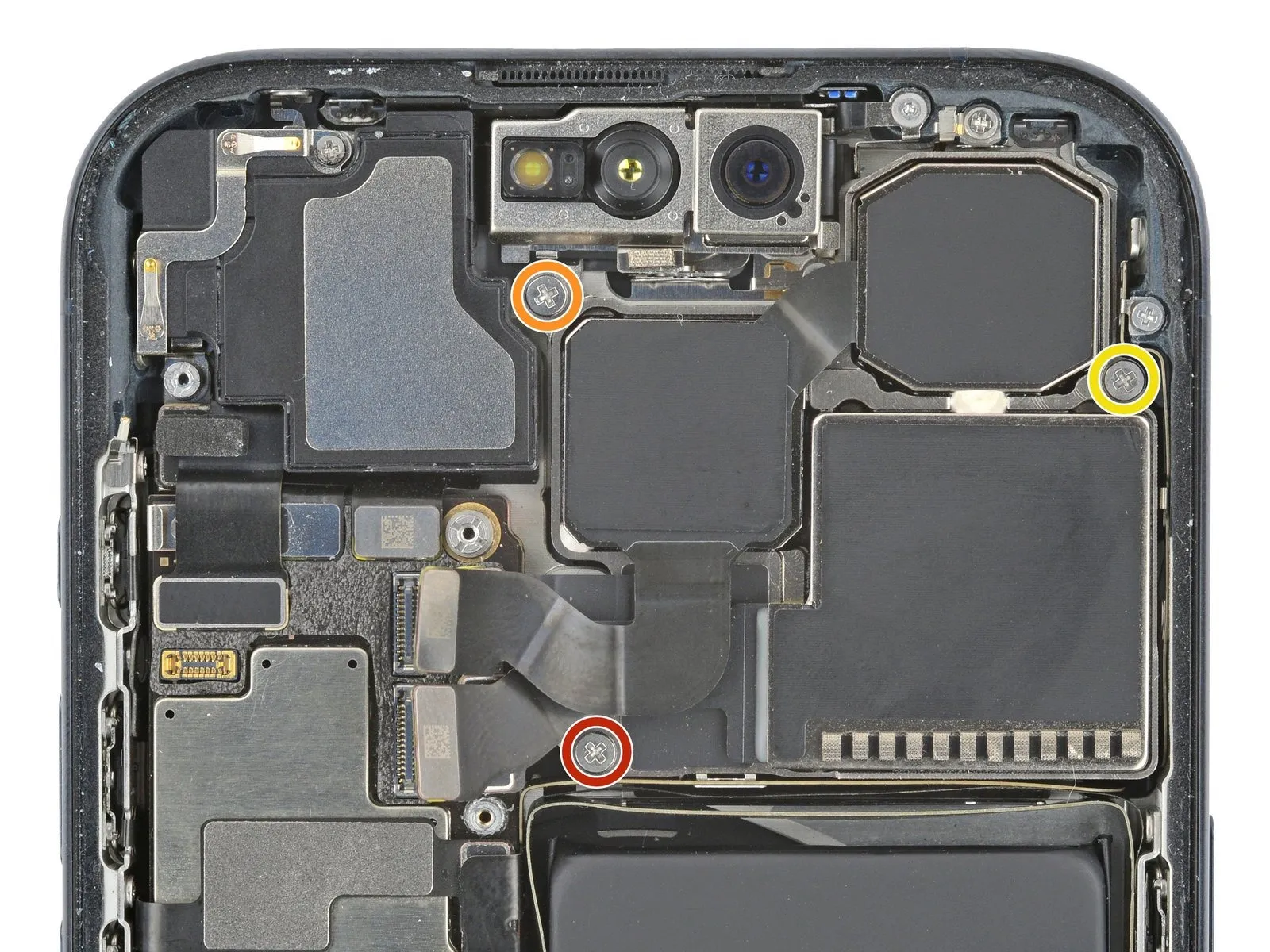

- Use a Phillips #000 screwdriver to remove the three screws securing the rear cameras:
A 3.8 mm-long screw
A 3.2 mm-long screw
A 2.8 mm-long screw
Step 26 | Remove the rear cameras
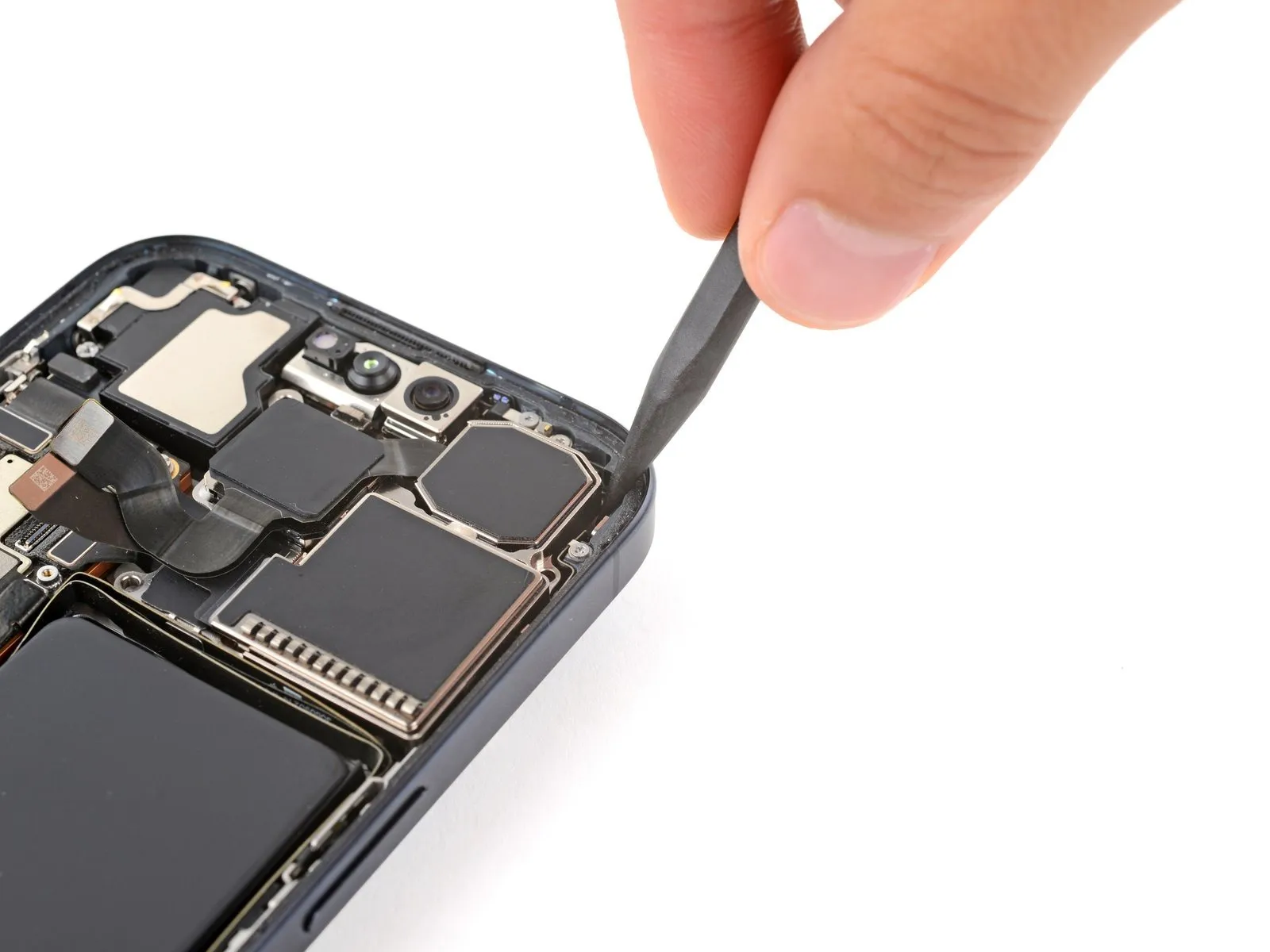


- Be careful not to touch or smudge the camera lenses during this step.
- Insert the point of a spudger between the top right corner of the rear cameras and frame.
- Pry up until you can grab the rear cameras with your fingers.
- Remove the rear cameras.
Step 27 | Disassembly complete

Congratulations on completing disassembly! The remaining steps show how to reassemble the iPhone.
Step 28 | Install the rear camera assembly


- Be careful not to touch or smudge the camera lenses.
- Align the rear camera assembly with its recess in the frame and set it into place.
Step 29 | Install the rear camera assembly screws
- Use a Phillips #000 screwdriver to install the three screws securing the rear cameras:
A one 3.8 mm-long screw
A one 3.2 mm-long screw
A one 2.8 mm-long screw
Step 30 | Connect the rear cameras
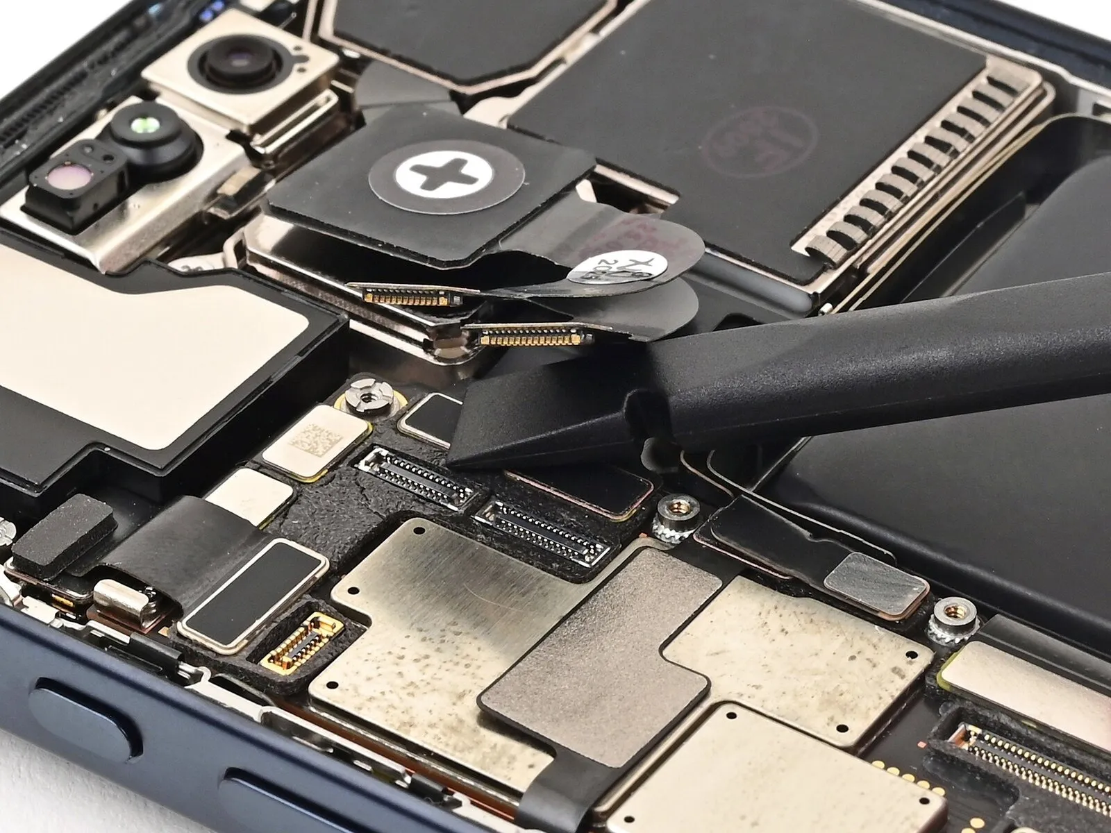


Use the flat end of a spudger to connect the three rear camera press connectors-starting with the black one-to their respective sockets on the logic board.
Step 31 | Remove the screen adhesive
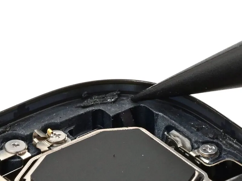
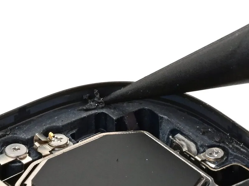
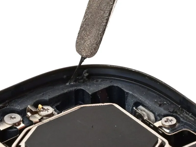
- The adhesive remaining on the phone is difficult to remove and leaves residue. If you have trouble removing the adhesive, apply some heat using a hair dryer or heat gun.
Use a spudger to push the screen adhesive up until you can grab it with a pair of tweezers.
Use a pair of tweezers, or your fingers, to remove the adhesive around the entire perimeter of the iPhone.
Step 32
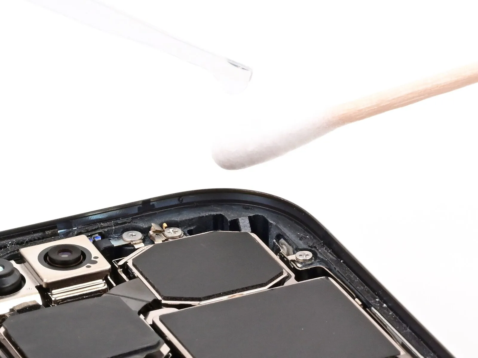
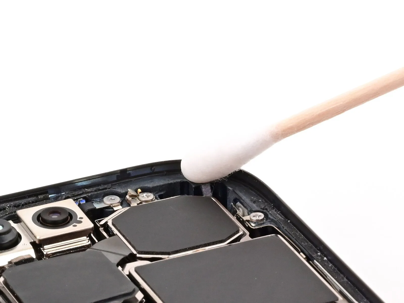
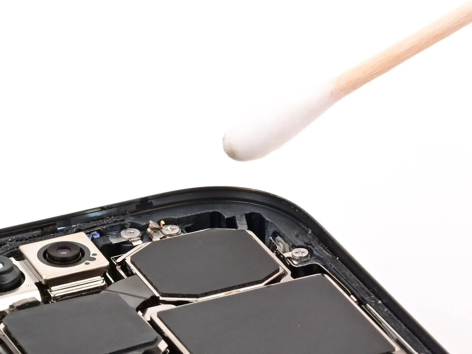
- Any unevenness will compromise the iPhone's seal. Clean the frame thoroughly.
Apply a few drops of high-concentration (greater than 90%) isopropyl alcohol to a cotton swab or lint-free cloth.
Wipe along the perimeter of the frame to clean the adhesive residue.
Wait a few minutes before proceeding to make sure any excess alcohol has evaporated.
Step 33 | Orient the adhesive

Step 34 | Apply the adhesive

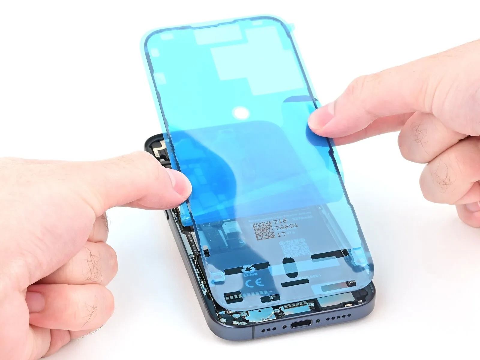
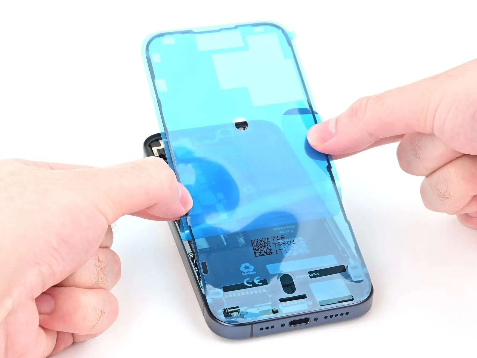
- Once the adhesive is pressed into place, you can't reposition it-you'll have to remove it and start over with new adhesive.
- Use the pull tab to begin peeling the back liner off of the adhesive starting from the bottom, but don't remove it all the way.
- While holding the back liner out of the way, carefully align the exposed edge of the adhesive to the bottom edge of the iPhone's frame.
- When the adhesive is aligned, set it down along the bottom edge.
Step 35
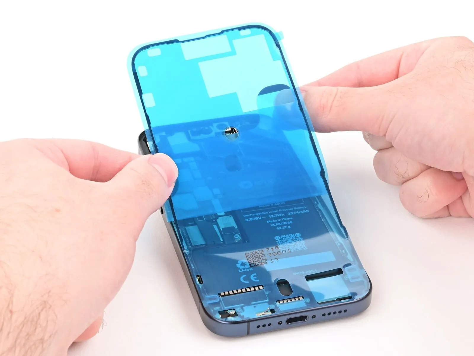
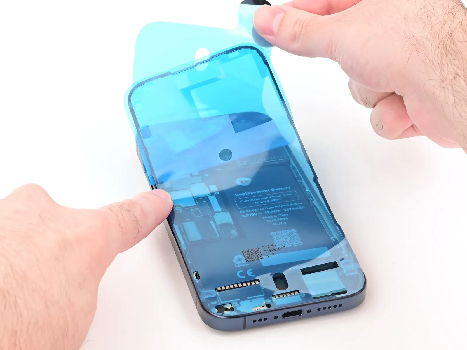
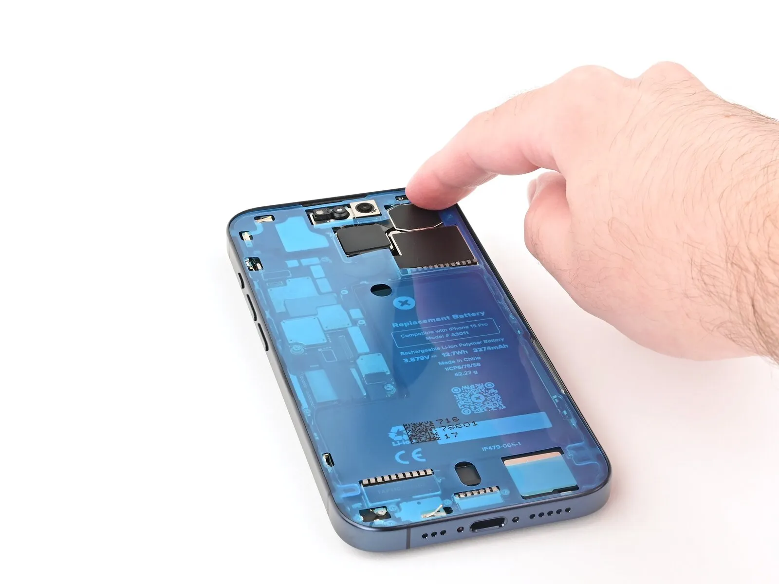
- Continue peeling the back liner off of the adhesive while setting the adhesive into place along the edges of the iPhone's frame.
- If you correctly aligned the lower edge of the adhesive, the side and top edges will fall perfectly into place. If the adhesive is misaligned, remove it and start over with new adhesive.
- If you don't have another one handy, it's okay to put your iPhone back together without adhesive, but keep in mind that it won't be water resistant until you install new adhesive.
Step 36 | Press the adhesive into place
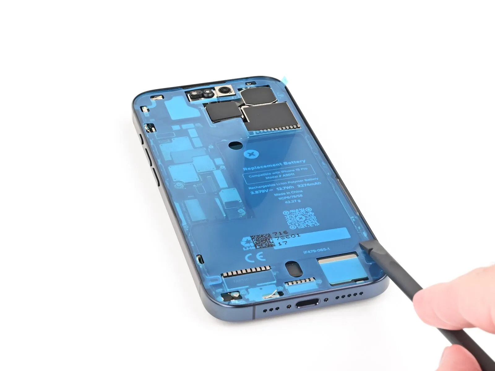
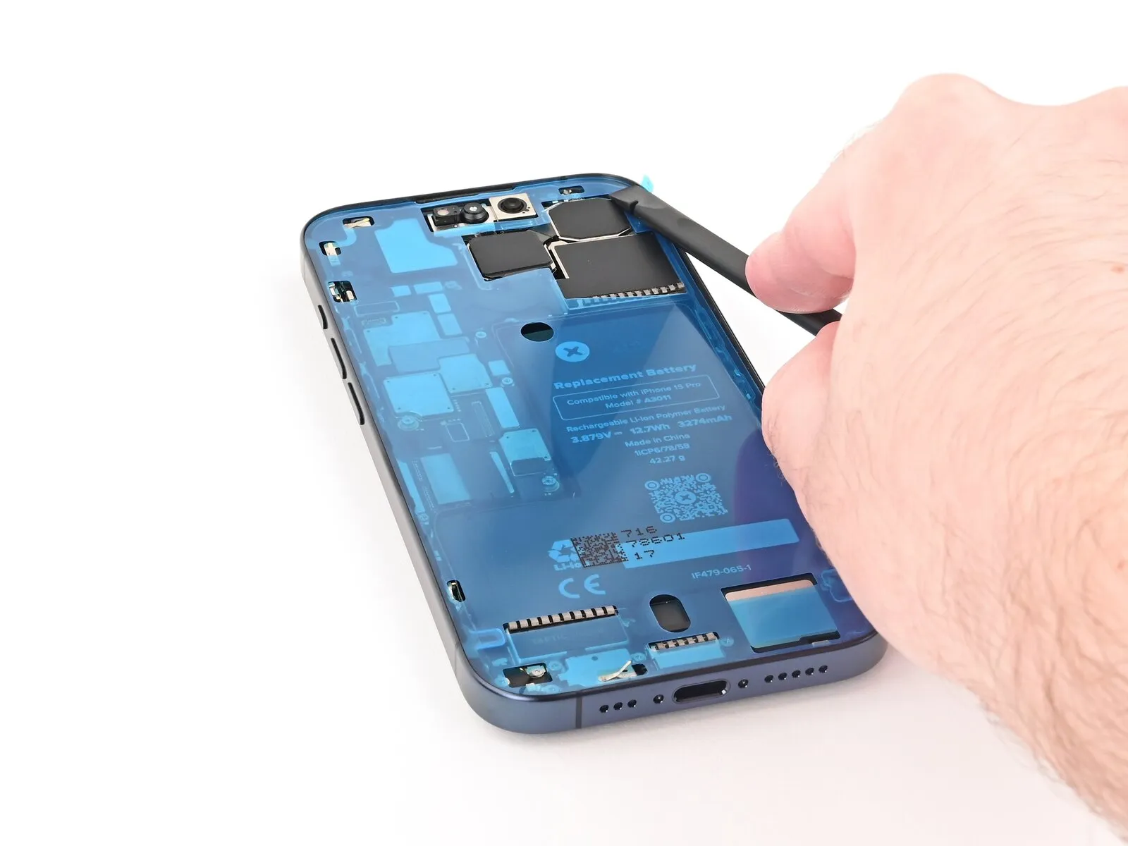
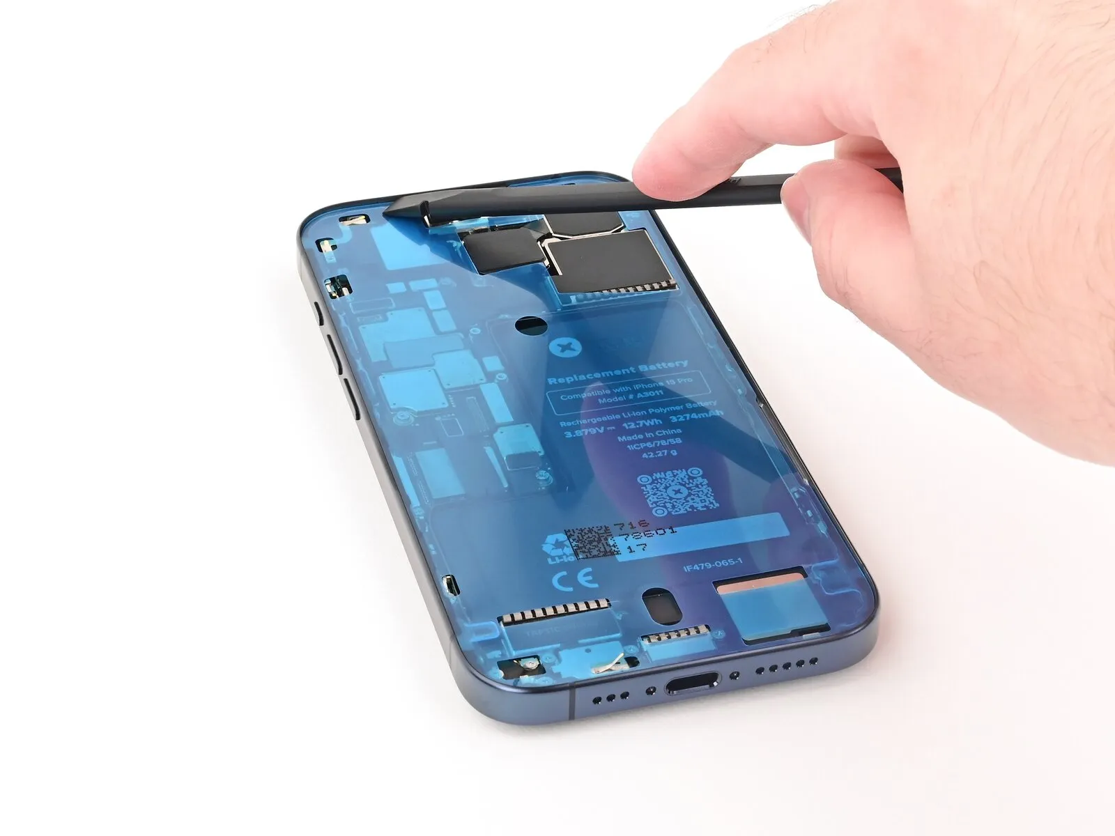
- Use the flat end of a spudger to press the adhesive into place all around the iPhone.
- Be careful not to press on the camera, spring contacts, or other internal components.
Step 37 | Remove the top liner

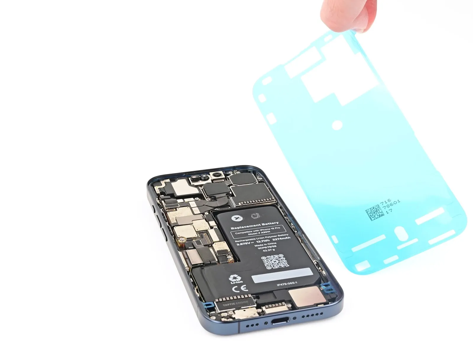
- Lift the pull tab in the top-right corner of the frame to peel off the top liner and remove it.
- Your pull tab may be in a different location. Make sure you're pulling the full-size top liner, not the thin liners along the edges.
Step 38 | Adhesive information
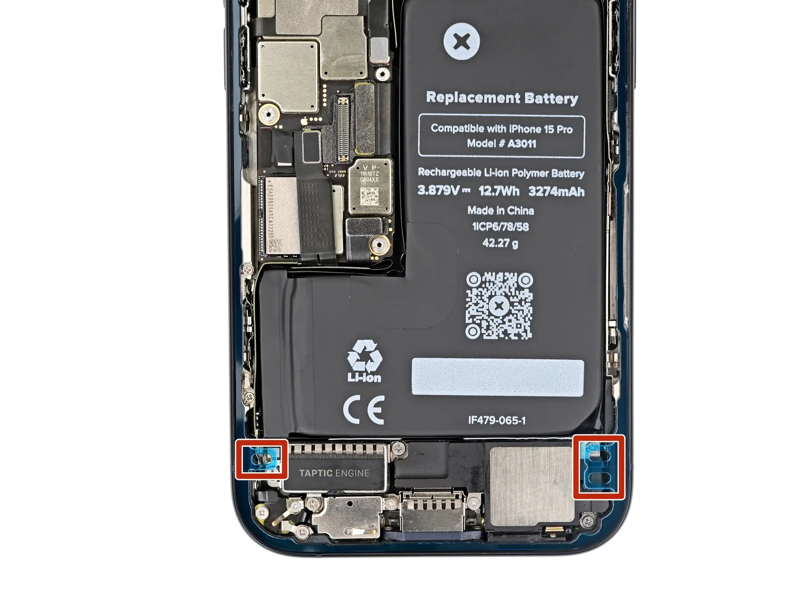
- Once the top liner is removed, there should be three narrow liners on top of the adhesive with pull tabs near the bottom edge.
- Your pull tabs may be in different positions.
- If you don't see these pull tabs, you may have accidentally removed the thin liners in the previous step. Be careful not to touch anything to the exposed adhesive.
Step 39 | Prop up the screen

Prop the screen up along the left edge of the iPhone frame, using a box or similar sturdy object to support the screen.
Step 40 | Connect the screen and ambient light sensor

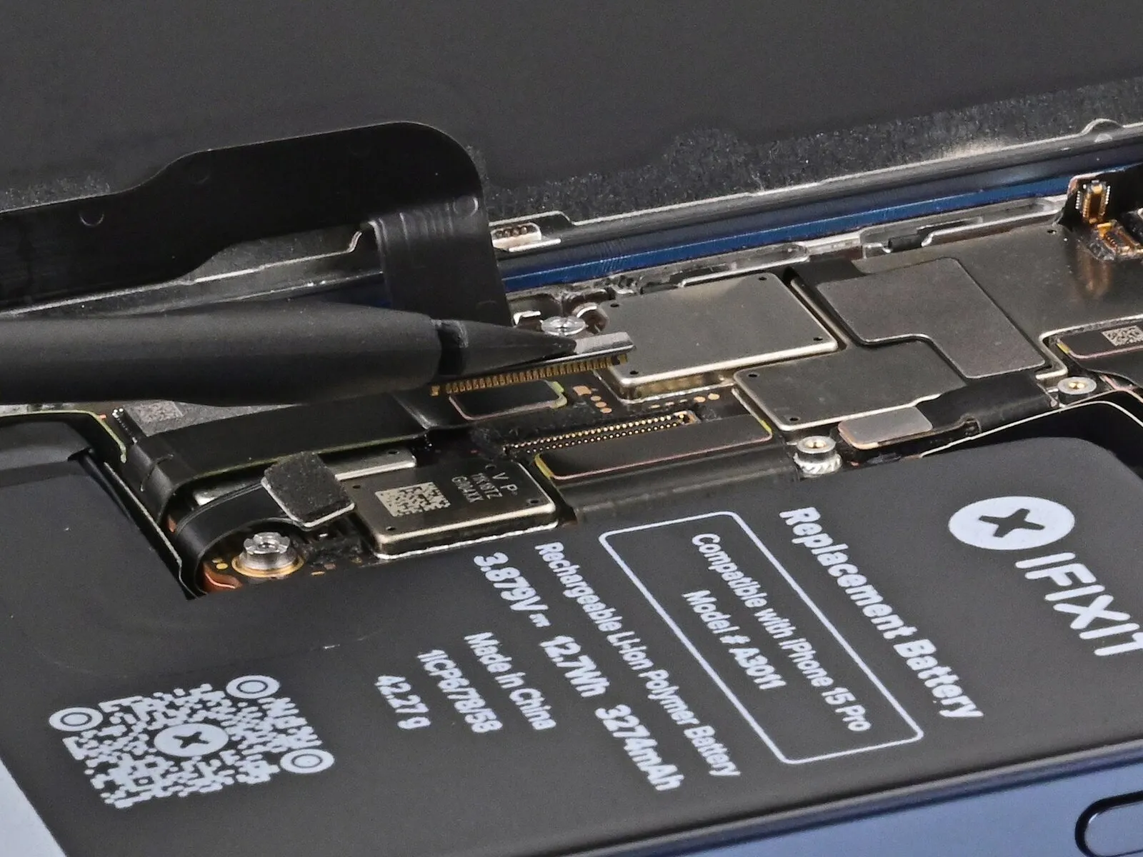
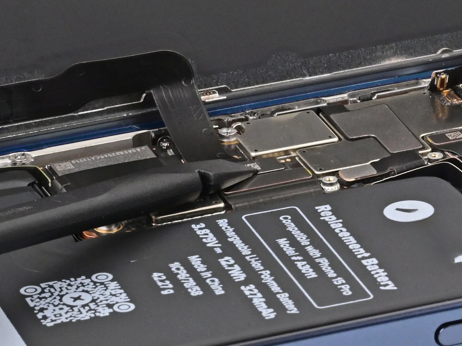
Use your finger or the flat end of a spudger to connect the screen and ambient light sensor press connectors.
Step 41 | Connect the battery

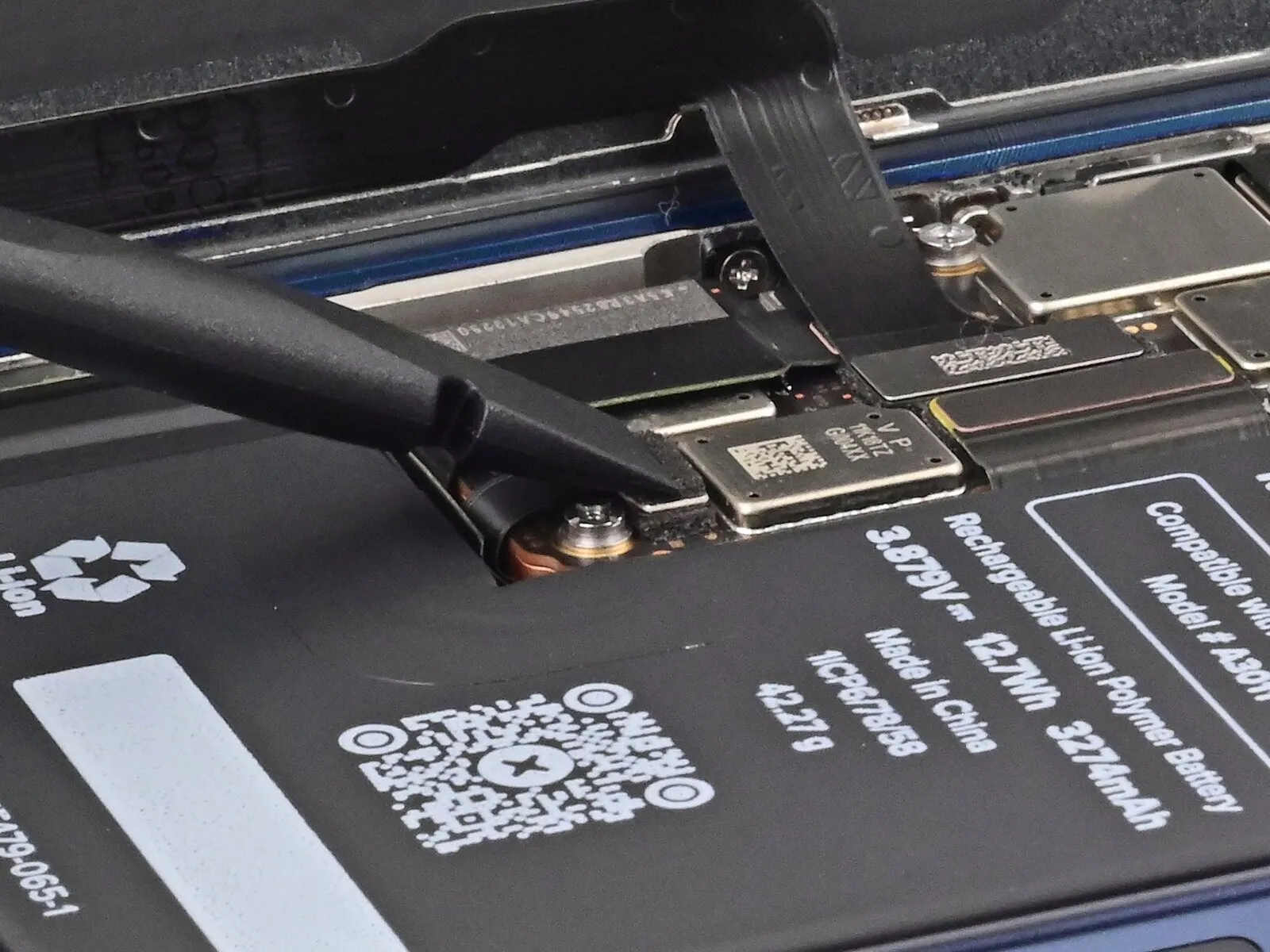
Step 42 | Install the logic board cover
Step 43 | Fasten the logic board cover
- Four 1.6 mm-long screws
- Two 1.3 mm-long screws
Step 44 | Remove the final adhesive liners

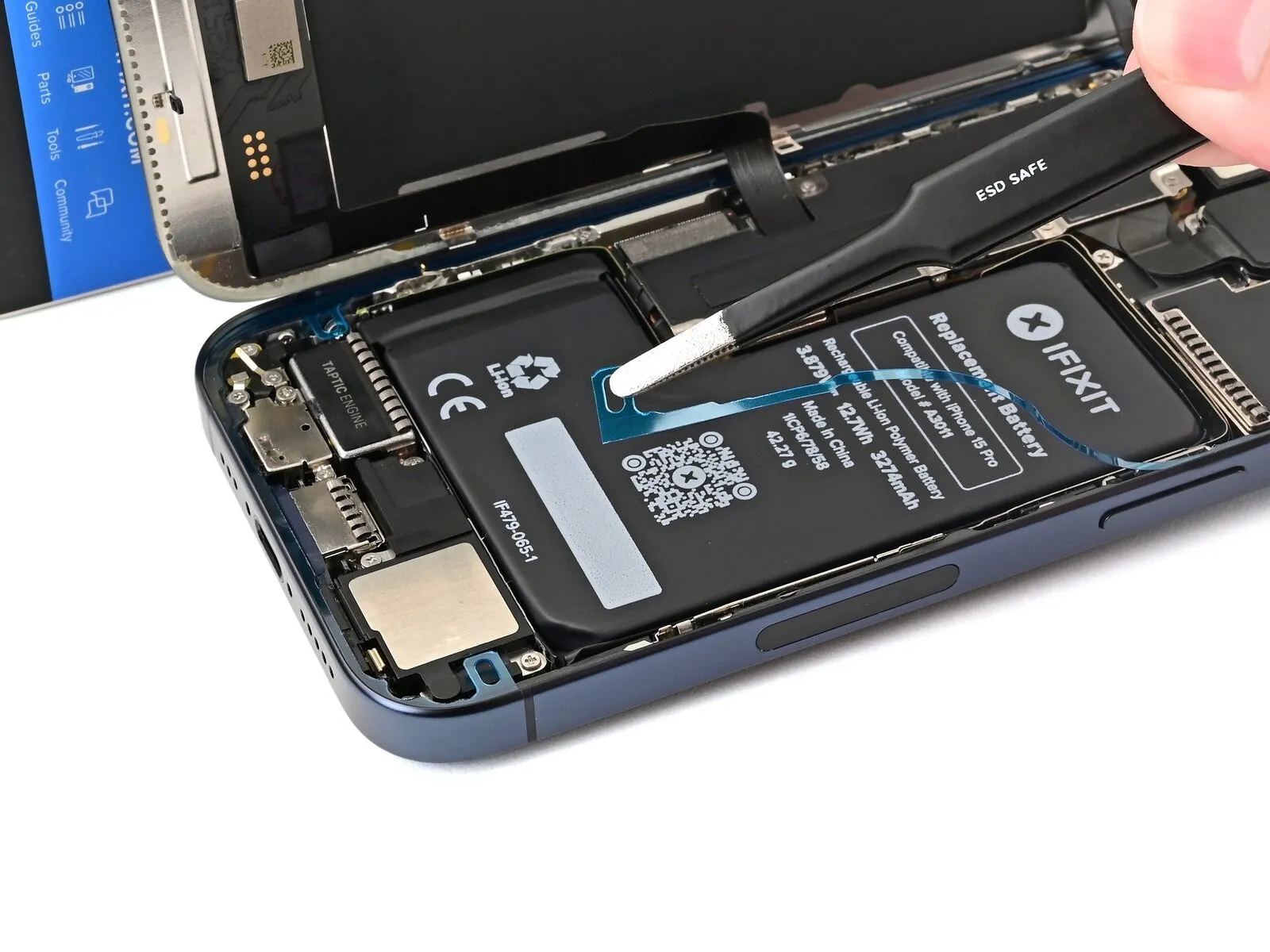
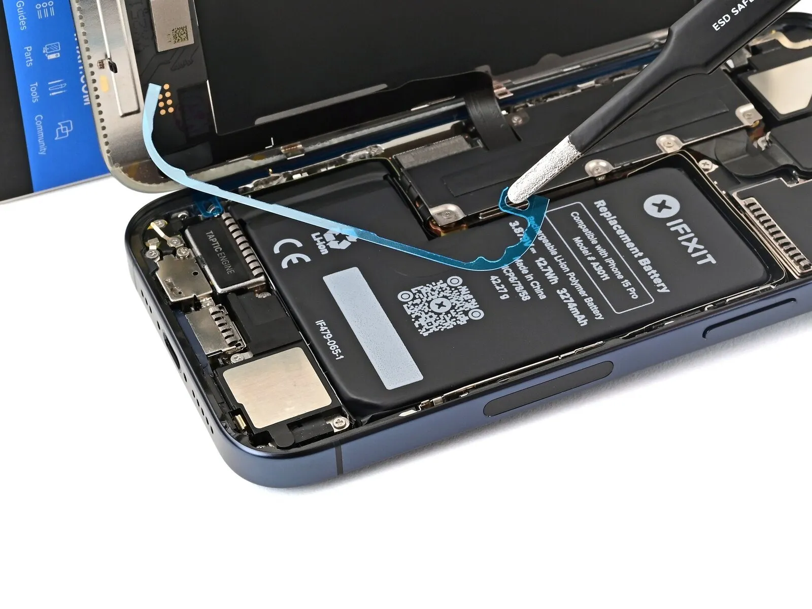
Make sure nothing accidentally sticks to it.
Use tweezers to remove the two narrow liners covering the adhesive along the right, top, and bottom edges of the frame.
Step 45

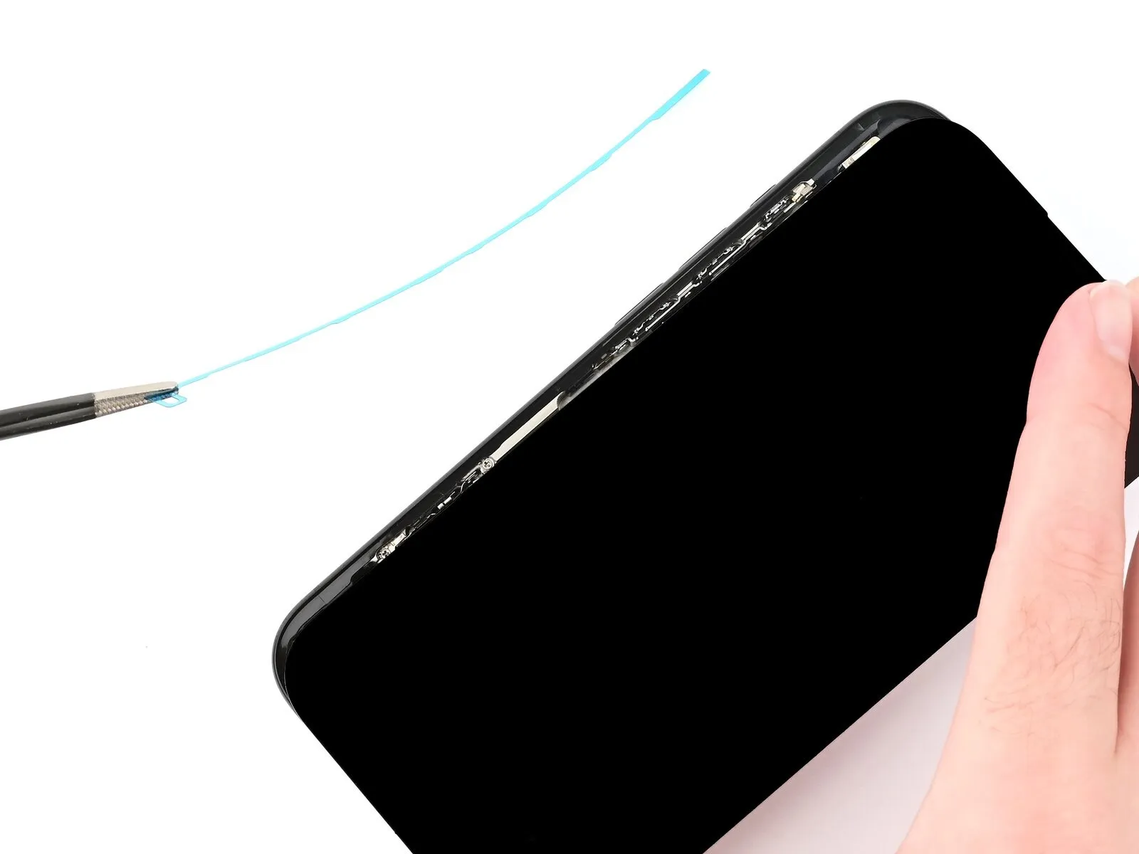
- Without letting the screen touch the adhesive, hold the screen over the phone so you can access the final liner along the left edge of the frame.
- Use a pair of tweezers or your fingers to remove the final liner along the left edge of the frame.
Step 46 | Place the screen
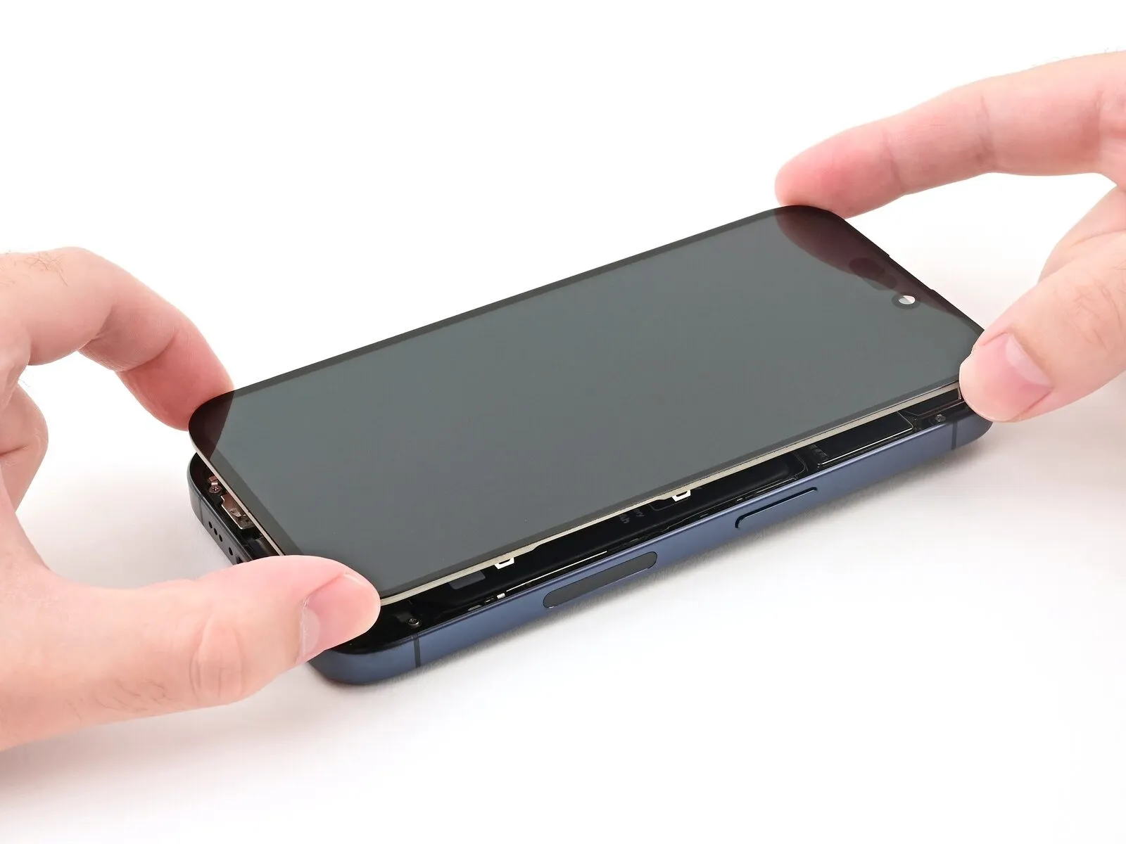
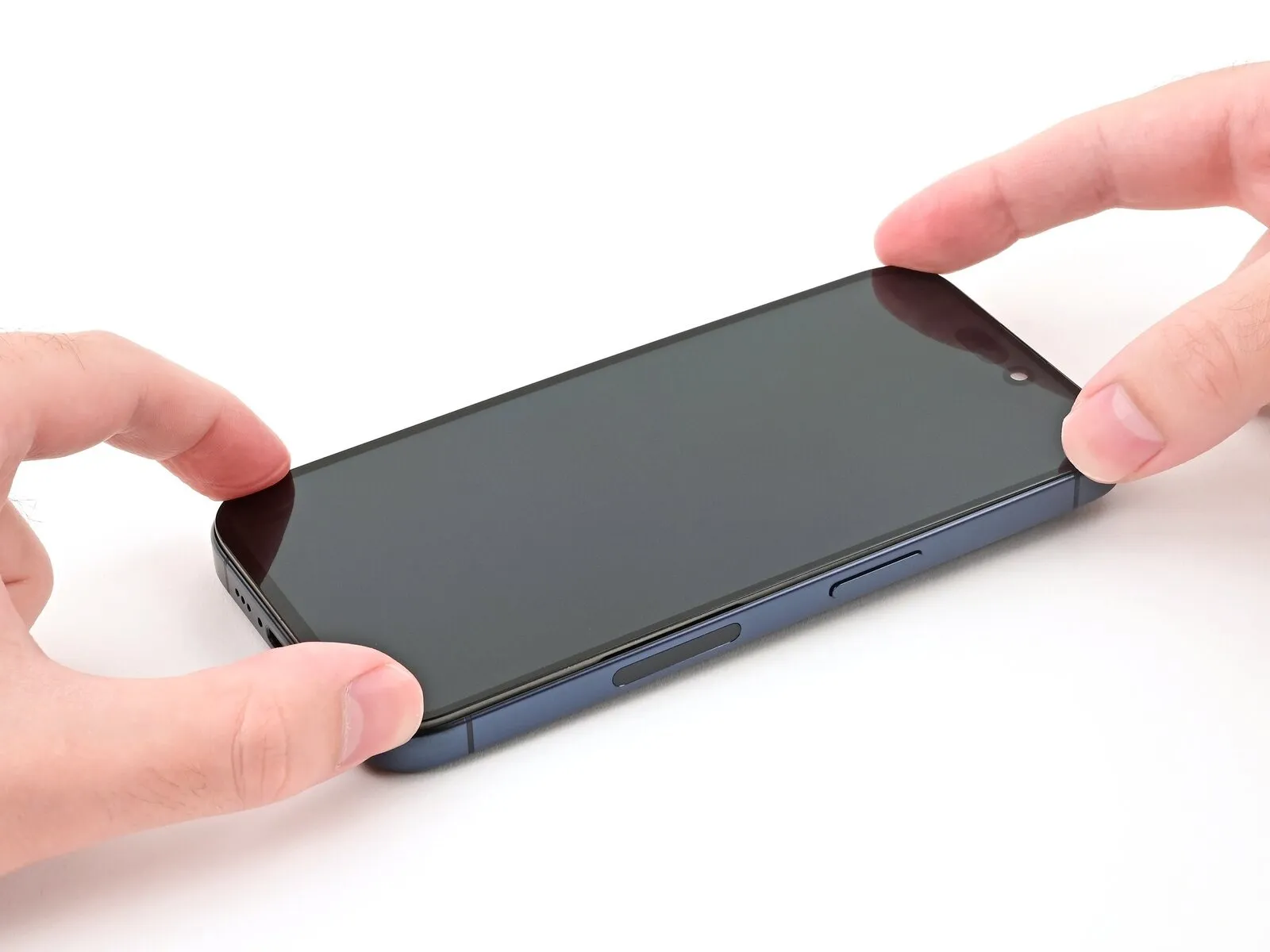
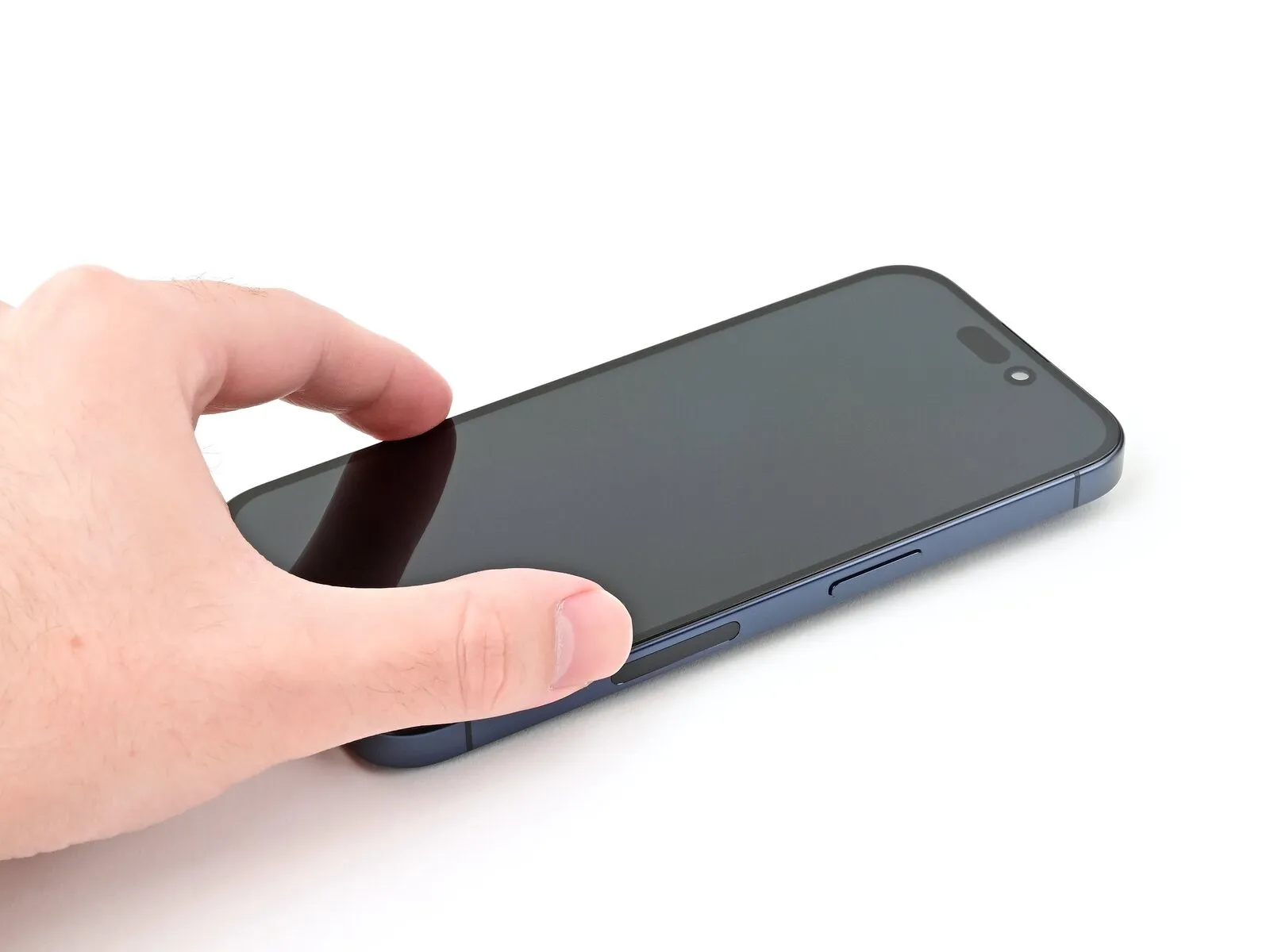
Step 47 | Press the screen
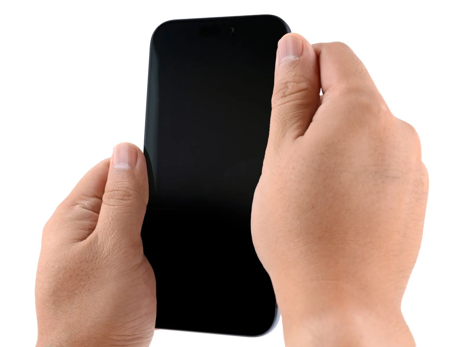
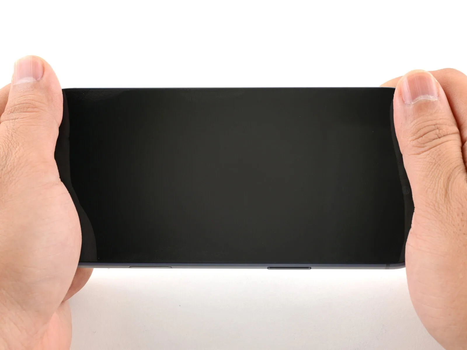
Step 48 | Install the pentalobe screws
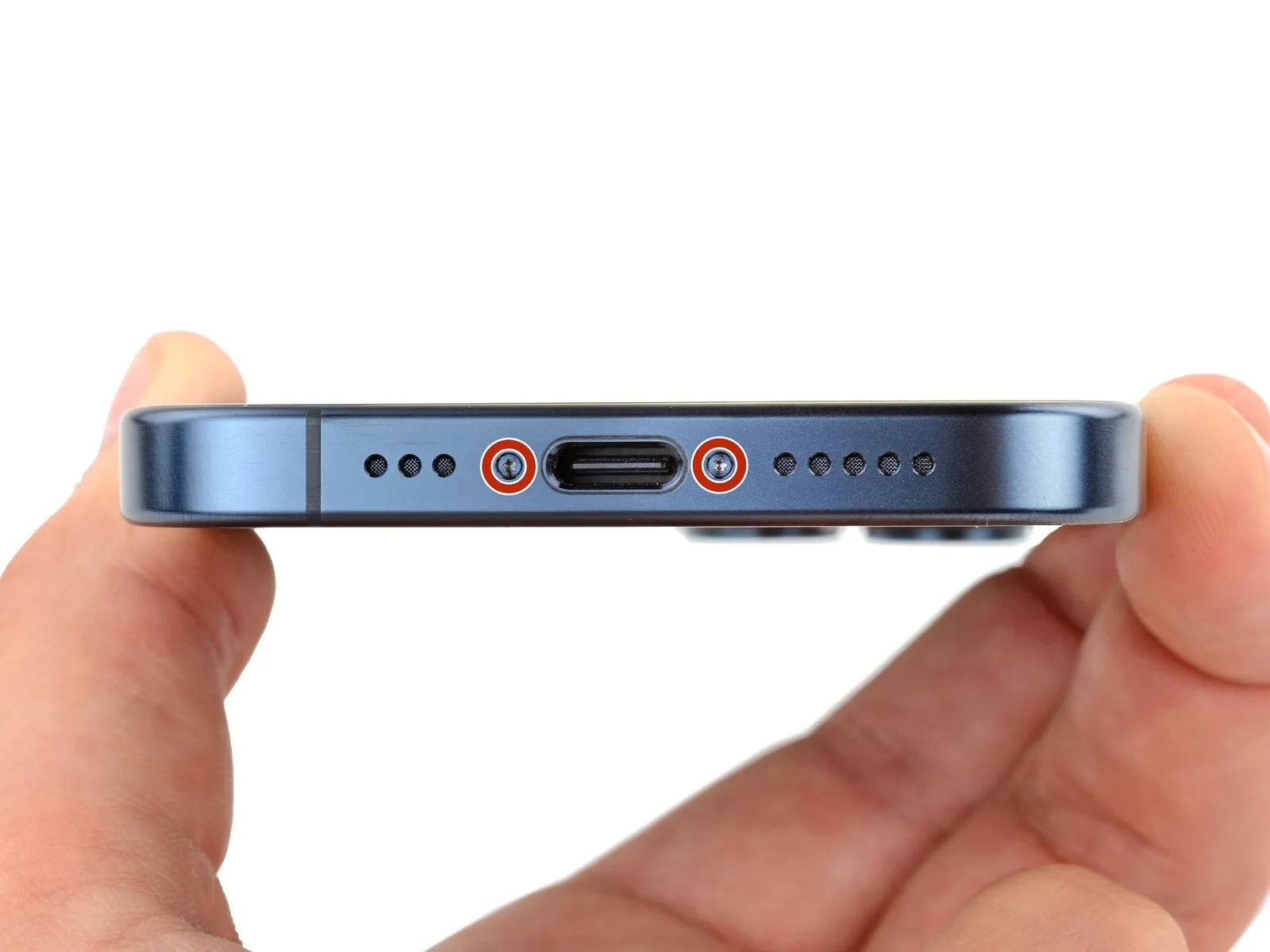
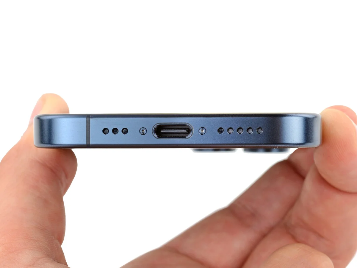
- Use a P2 pentalobe screwdriver to install the two 7 mm-long screws on either side of the charging port.
Step 49 | Heat the screen

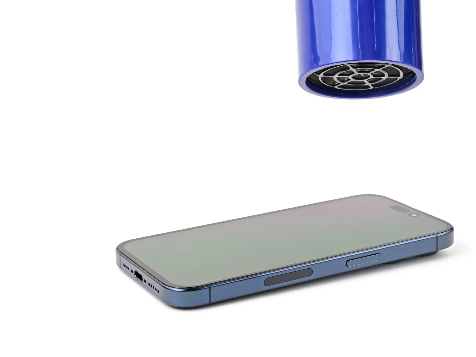
- To help the adhesive bond, apply heat to the edges of the screen using a hair dryer or heat gun until it's hot to the touch.
- If you have screen vise clamps, use them to strengthen the bond of the new adhesive. If not, keep reading for more ways to secure the screen.
Step 50 | Press the back glass

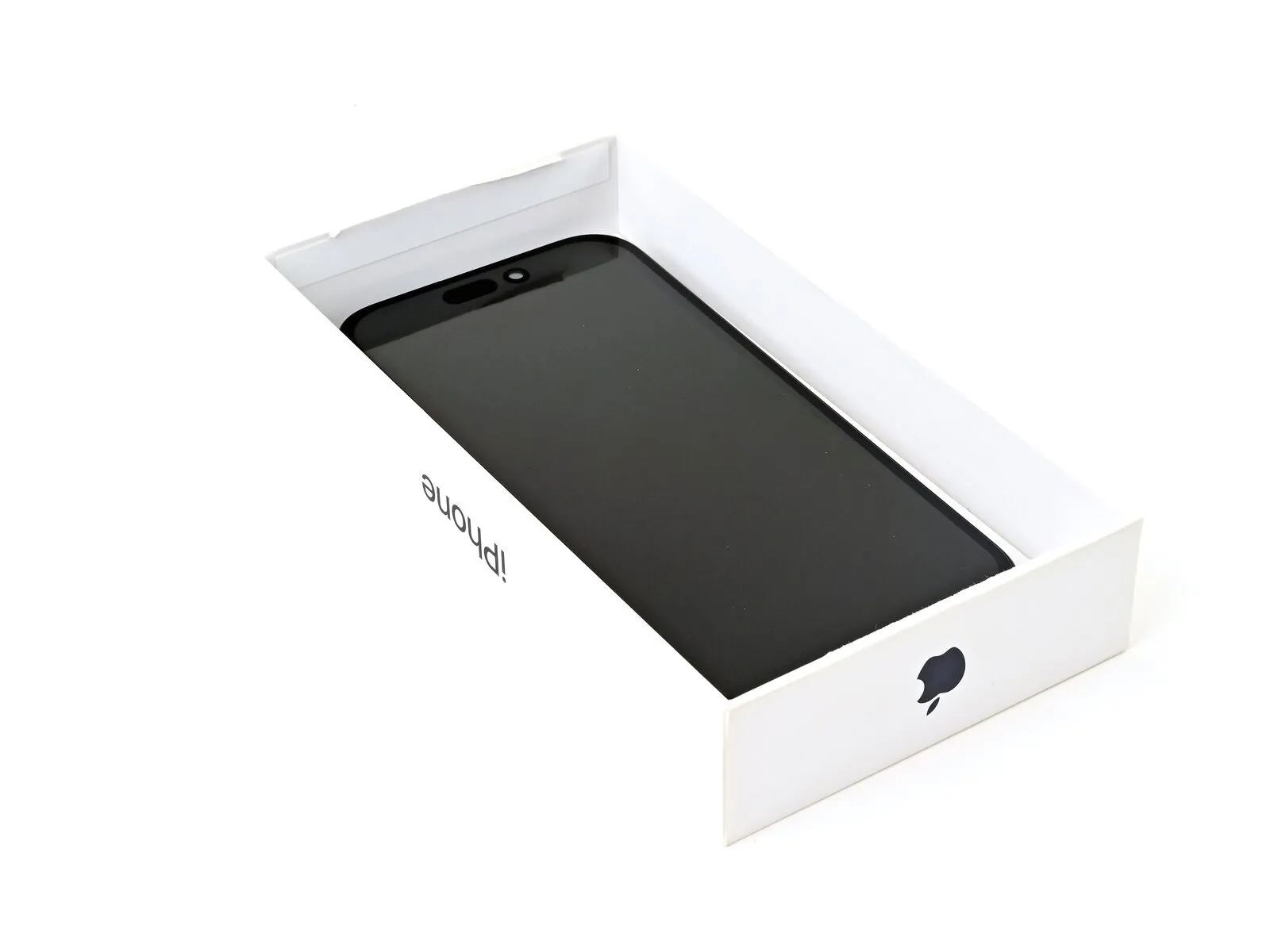

- To evenly compress the iPhone and strengthen the bond of the screen to the frame, you need to account for the camera bump.
- If you have the iPhone's original box, take the lid and place it on a flat surface.
- If you don't have the original box, skip this step for an alternate method.
- Place the iPhone screen-side-up in the lid of the box with the camera bump in its recess.
- Find something close to the size of the iPhone, but taller than the sides of the box. Stack it on top of the iPhone, followed by a few heavy objects.
- Leave the objects in place for at least thirty minutes, ideally overnight.
Step 51

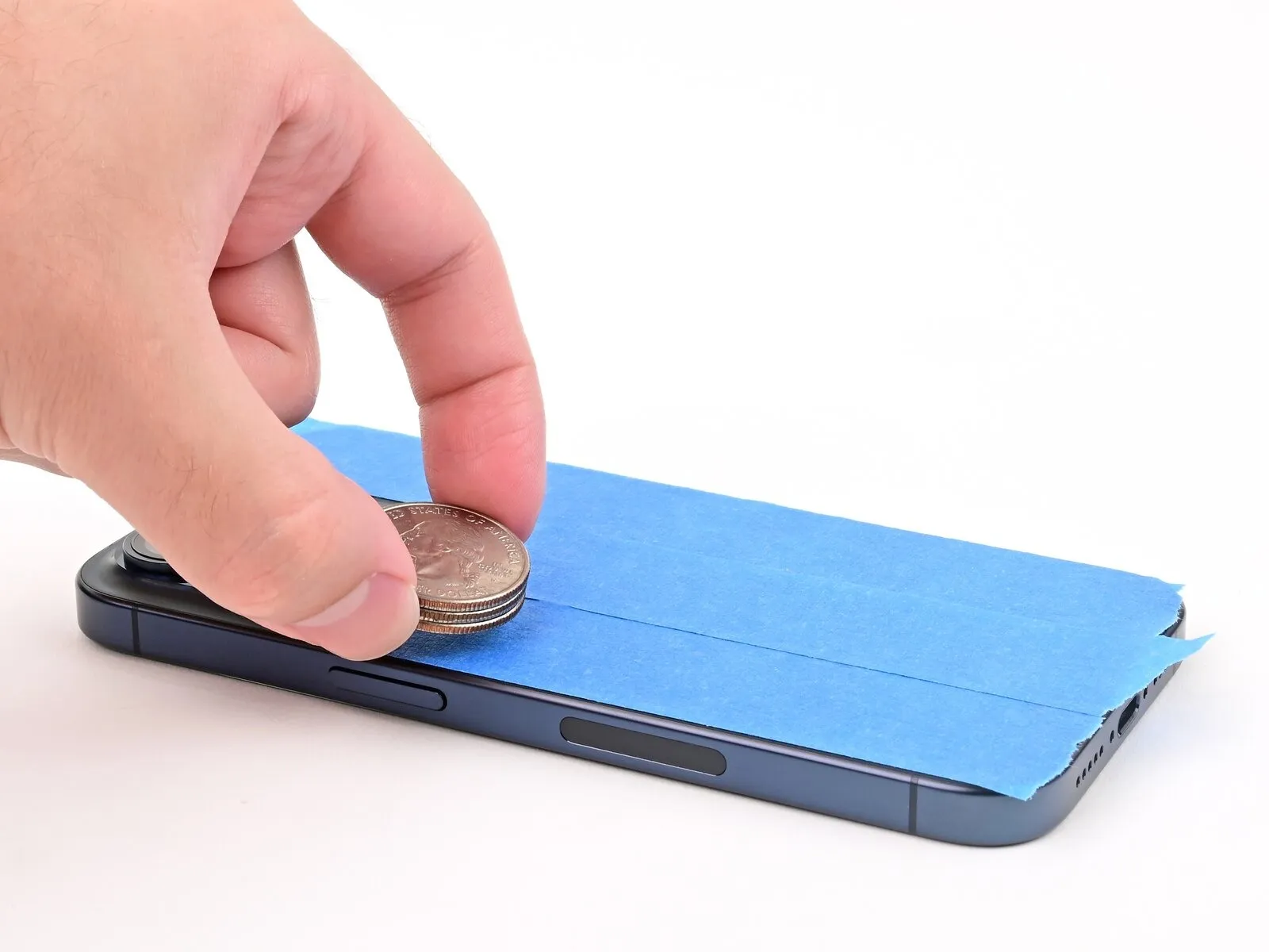

- Place the iPhone screen-side-down on a soft, flat surface.
- Apply tape to the back glass to protect its finish.
- Place three layers of coins or similarly thick objects on the tape along the edges of the back glass.
- Evenly distribute the coins and make sure they are at least as thick as the camera bump.
Step 52

- The coins may leave an impression on the bottom object, so don't use anything valuable.
- Leave the objects in place for at least thirty minutes, ideally overnight.