iPhone 15 Pro Max Screen Replacement
Use this guide to replace a broken or cracked screen in your iPhone 15 Pro Max.
- You'll need replacement screen adhesive to complete this repair.
Note: Due to Apple's parts pairing restrictions, on iOS 17.6 and earlier, True Tone and auto brightness are disabled after a screen replacement, even when using an original Apple screen. On newer iOS versions, these features may be restored automatically. If you're using an original Apple screen, you can use Repair Assistant to calibrate it with your iPhone.
Step 1 | Prepare your phone for disassembly
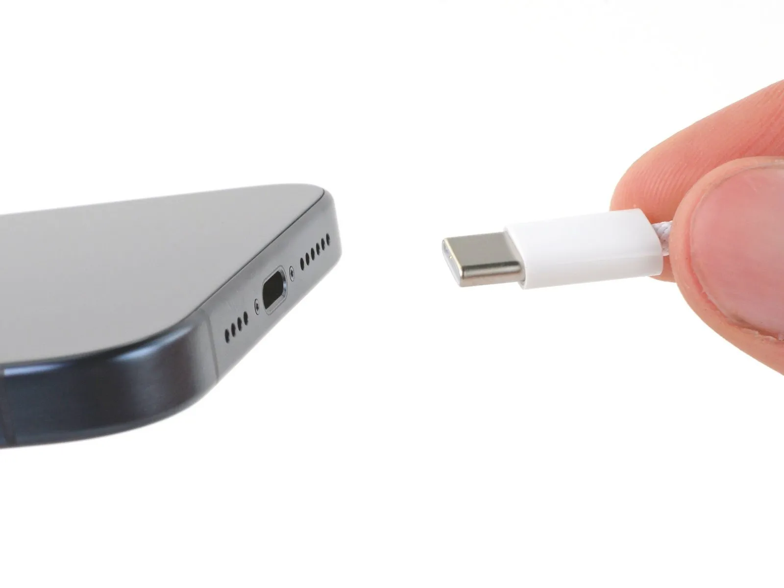
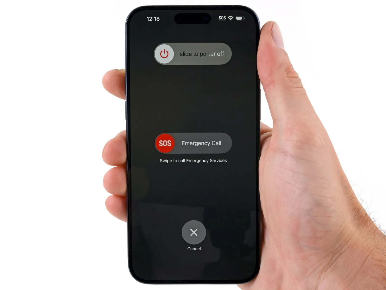
- Allow your phone's battery to drain below 25%, as a charged lithium-ion battery is a potential safety hazard.
- Unplug any cables from your phone.
- Hold the power and either volume buttons and slide to power off your phone.
Step 2 | Tape over any cracks
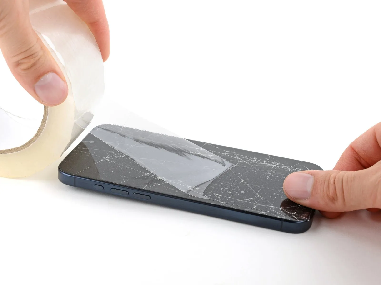
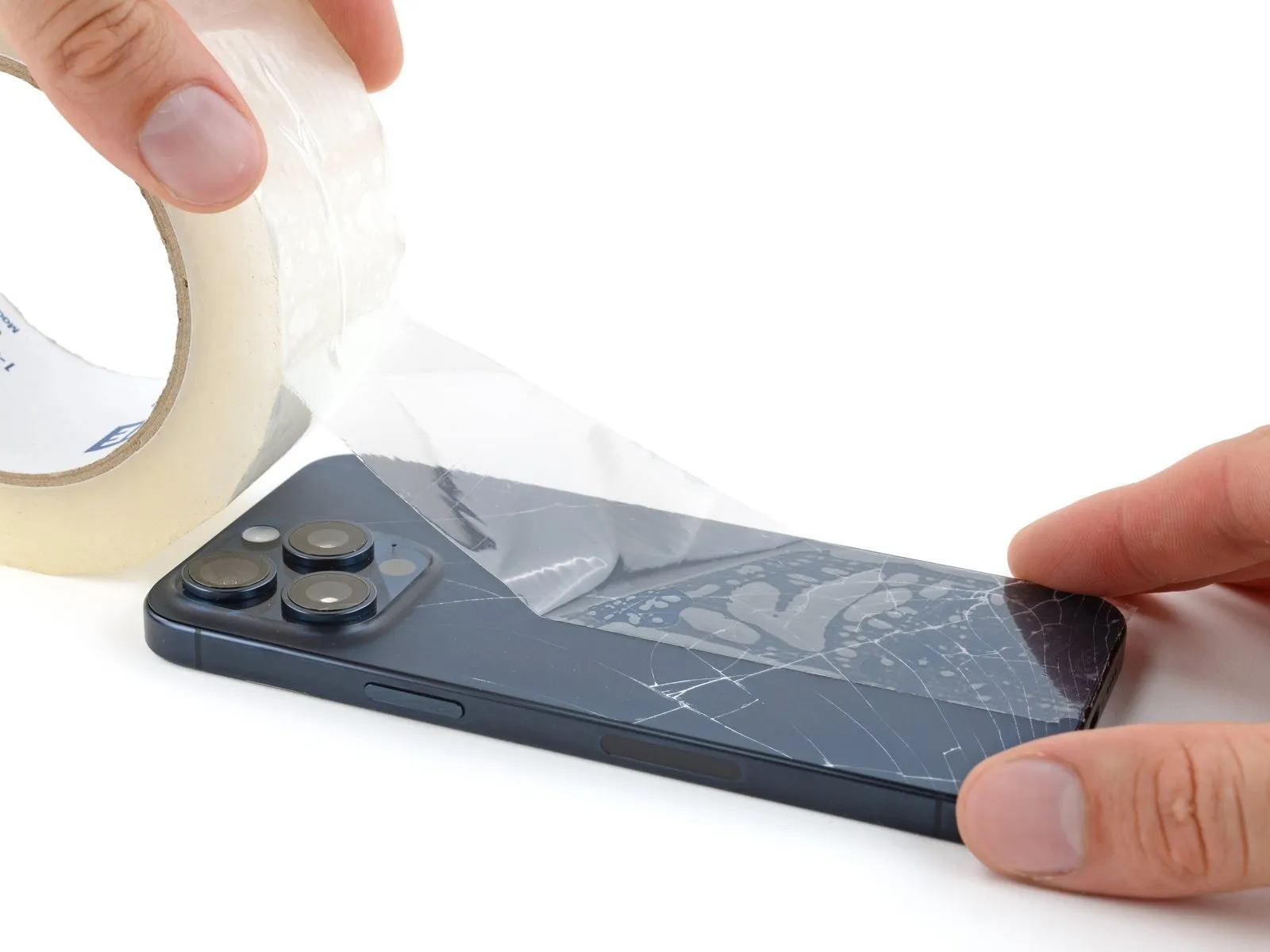
- If your screen or back glass is badly cracked, lay overlapping strips of packing tape over the glass to protect yourself and make disassembly easier.
- Make sure there's a smooth area near the bottom edge that's big enough for a suction cup to stick to.
Step 3 | Mark your opening picks


- If inserted too far, an opening pick can damage your device. Follow this step to mark your pick and prevent damage.
- Measure 3 mm from the tip and mark the opening pick with a permanent marker.
- You can also mark the other corners of the pick with different measurements.
- Alternatively, tape a coin to a pick 3 mm from the tip.
Step 4 | Remove the pentalobe screws
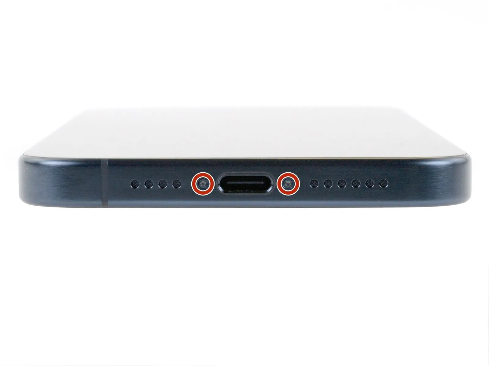
Use a P2 pentalobe driver to remove the two 7.2 mm-long screws on either side of the charging port.
Step 5 | Screen bezel information


- During the next two steps, make sure you're inserting your pick in the correct location:
- There's a plastic bezel on the underside of the screen that sits on the frame. Insert your pick here, making sure it's completely under the bezel.
- There's a seam between the plastic bezel and the display panel. Don't insert your pick here or you'll separate the two, complicating the repair.
Step 6 | Heat the bottom edge
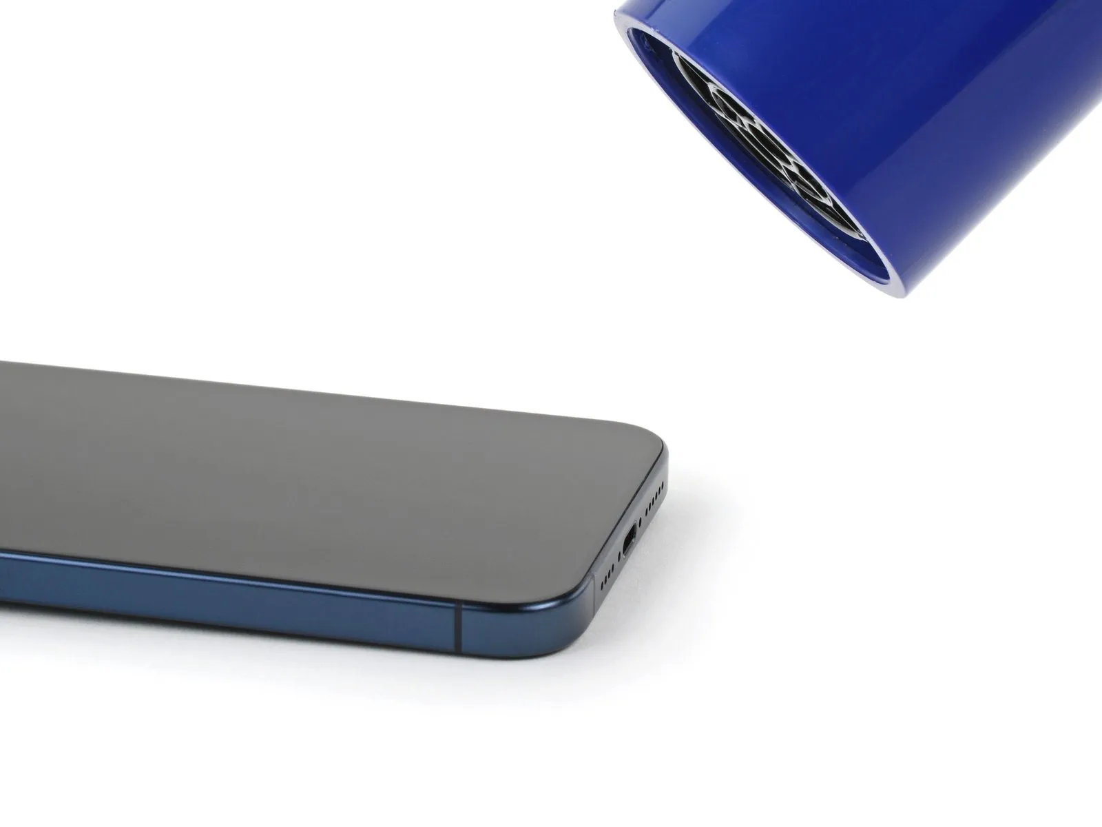
- Use a hair dryer or heat gun to heat the bottom edge of the screen until it's hot to the touch:
- Be careful not to heat the phone hotter than this-the battery is susceptible to heat damage.
Step 7 | Insert an opening pick
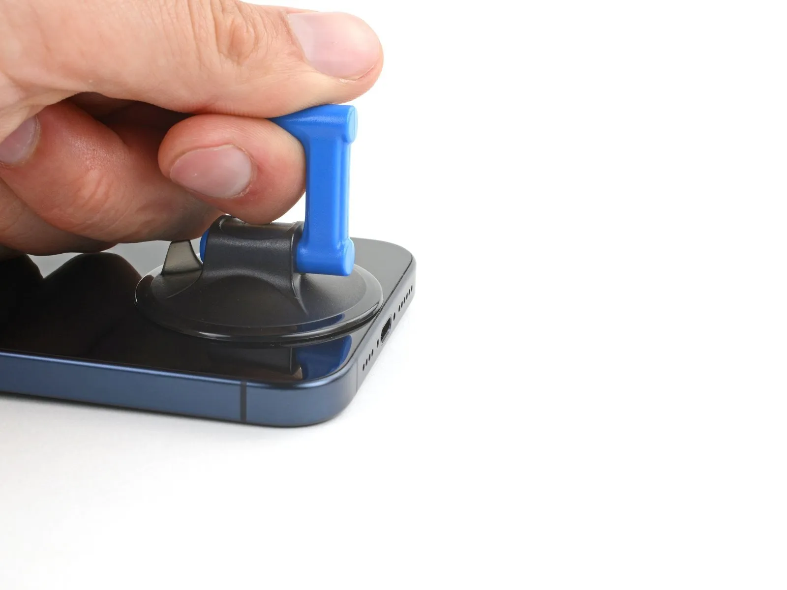
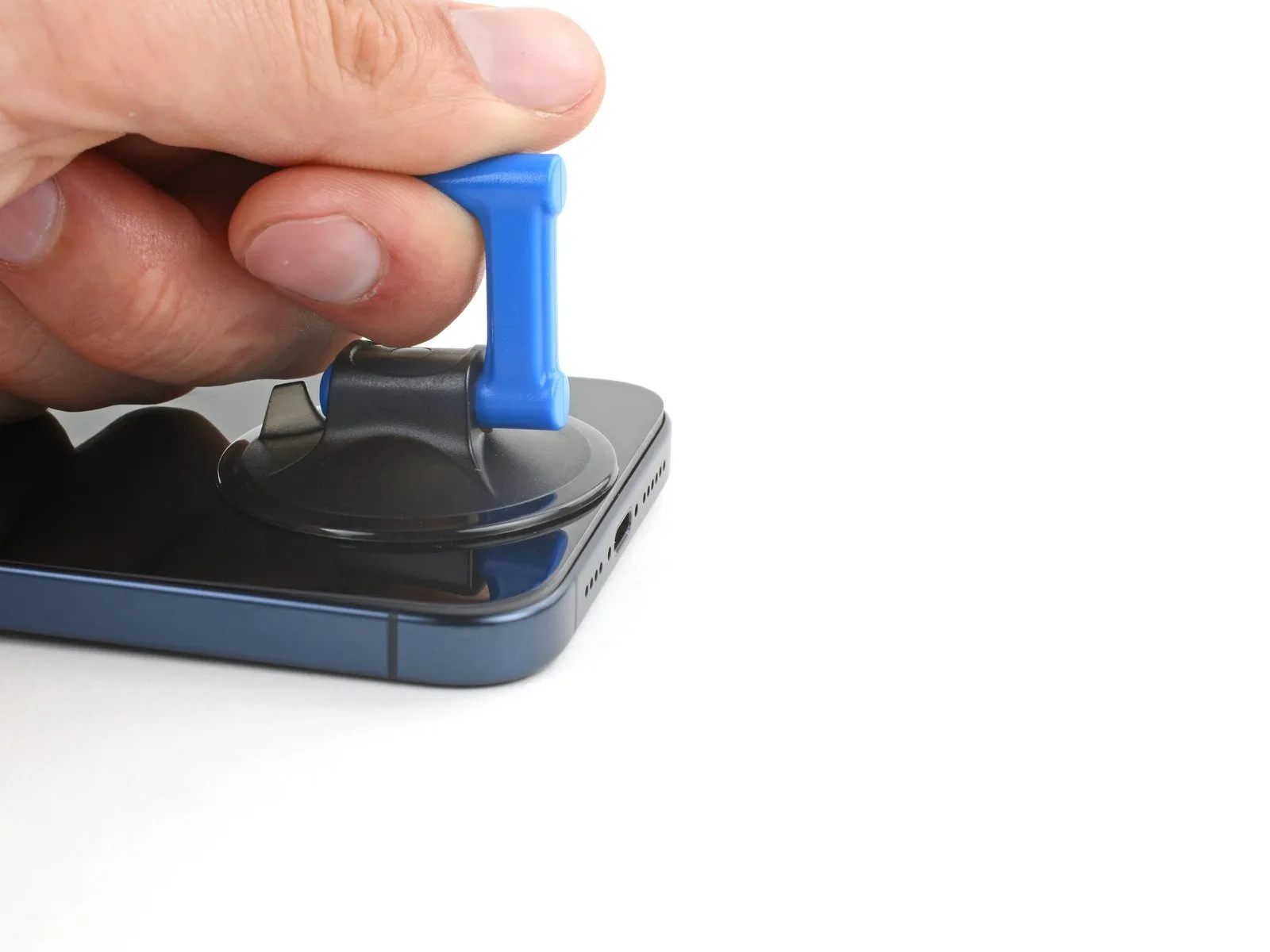
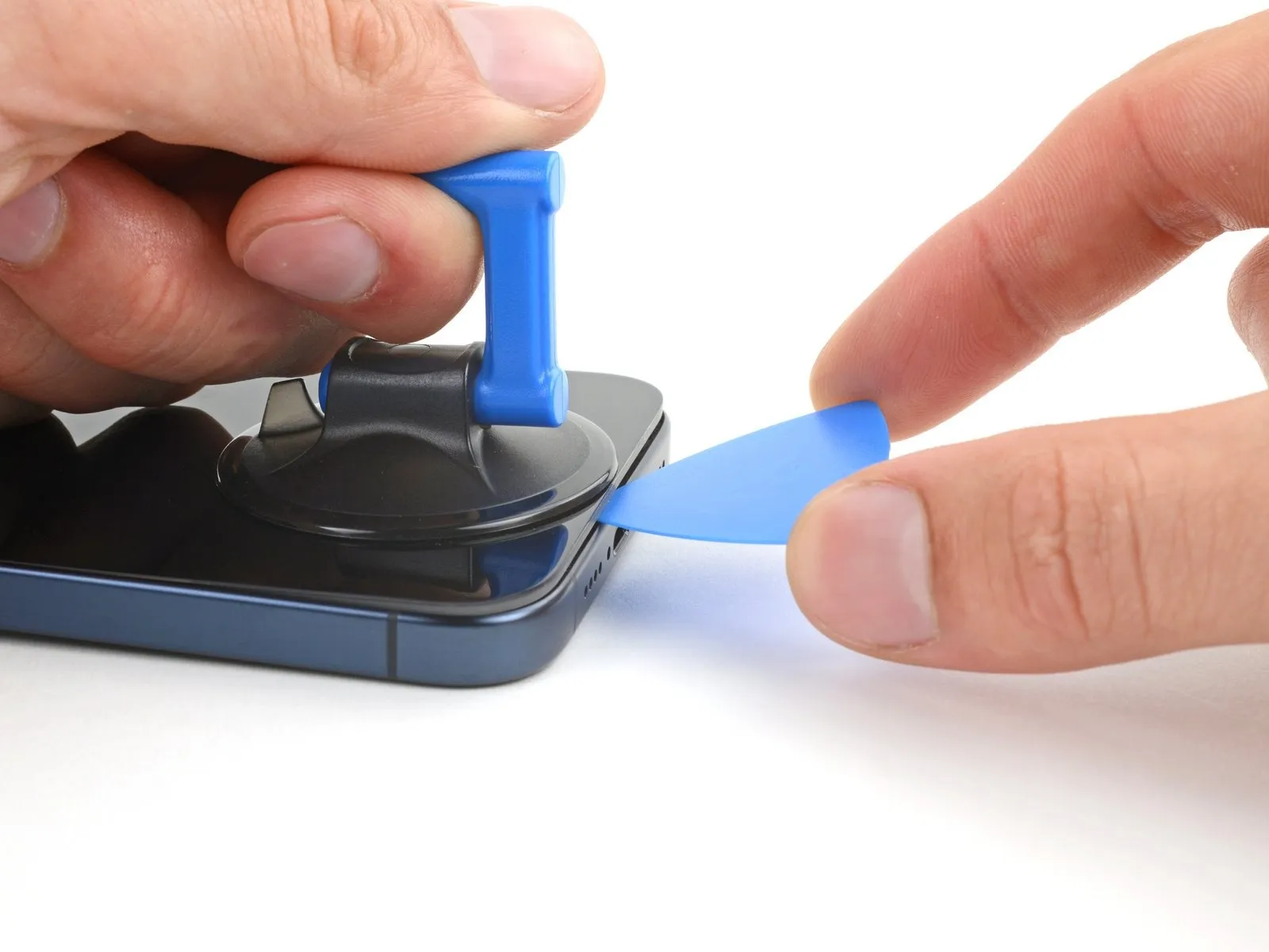
- Apply a suction handle to the bottom edge of the screen:
- Pull up on the handle with a strong, steady force to create a gap between the screen and the frame.
- Insert the tip of an opening pick into the gap.
Step 8 | Screen information

- As you slice the adhesive securing the screen in the next steps, be careful of the following areas:
- There are two delicate cables connecting the screen to the phone: one just above the action button, and the other near the middle of the left edge.
- There are multiple spring contacts around the perimeter of the phone. Be extra careful not to insert your pick deeper than suggested in these locations to avoid bending the contacts.
Step 9 | Separate the bottom edge adhesive


- Don't insert your opening pick deeper than 3 mm along the bottom edge.
- Slide your pick back and forth along the bottom edge to separate the adhesive.
- Leave your pick inserted in the bottom right corner to prevent the adhesive from re-sealing.
Step 10 | Heat the right edge
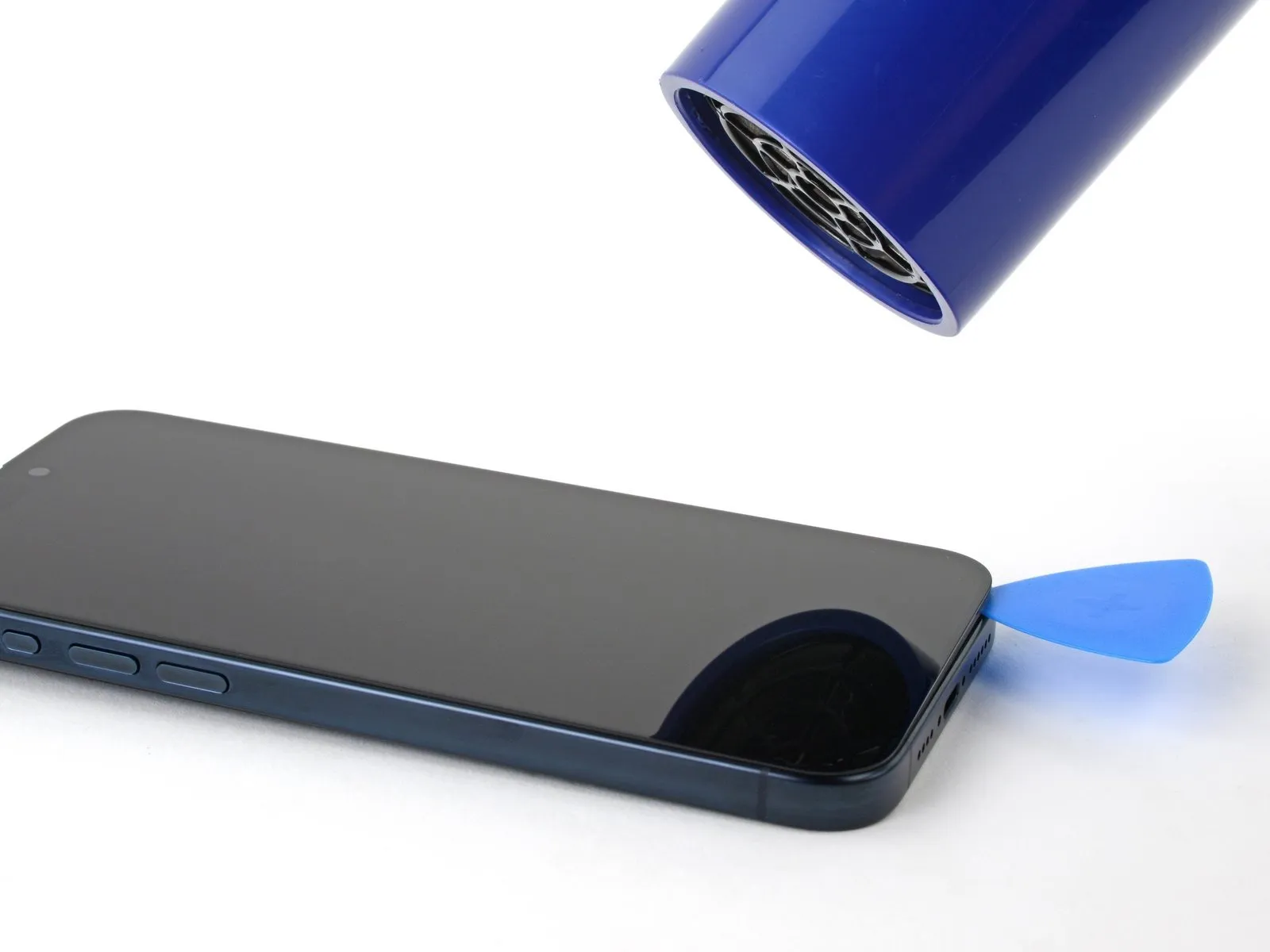
Step 11 | Position the opening pick
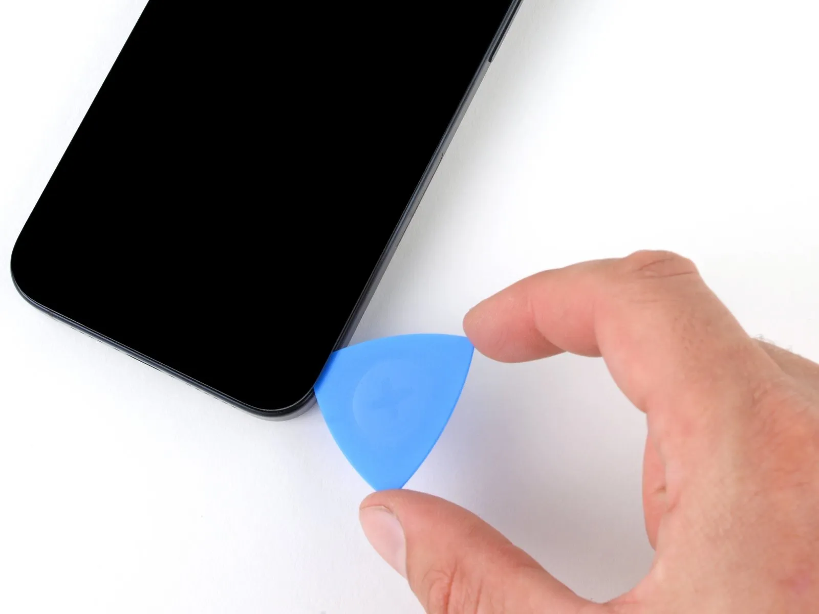
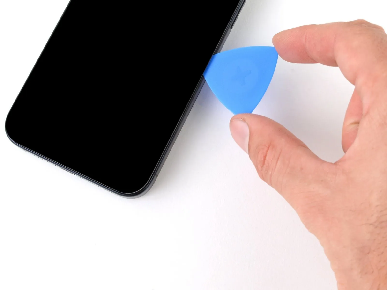
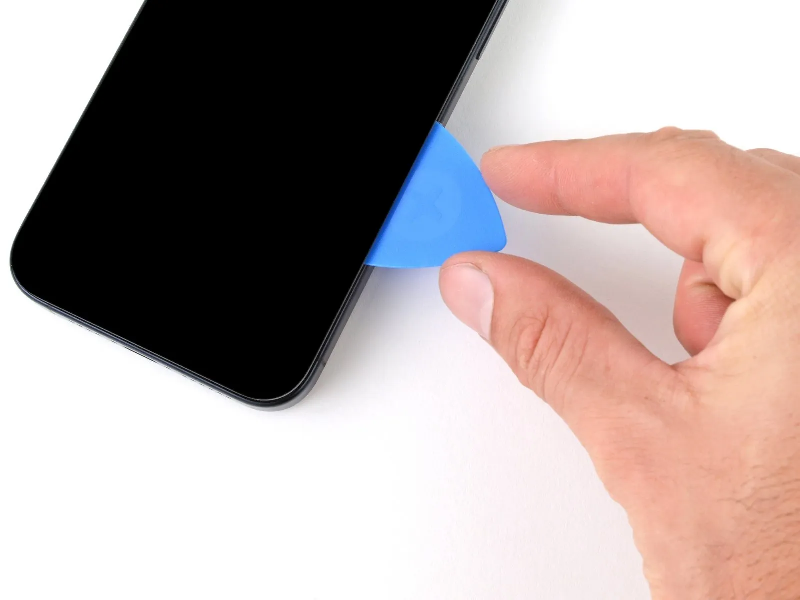
- Don't insert your pick deeper than 5 mm along the right edge.
- Slide your pick around the bottom right corner of the screen and toward the power button until you feel a hard stop at a clip securing the screen.
- Rotate your pick so the flat edge is under the screen.
Step 12 | Release the right clip
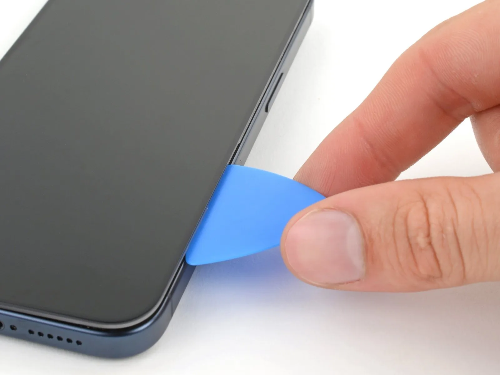
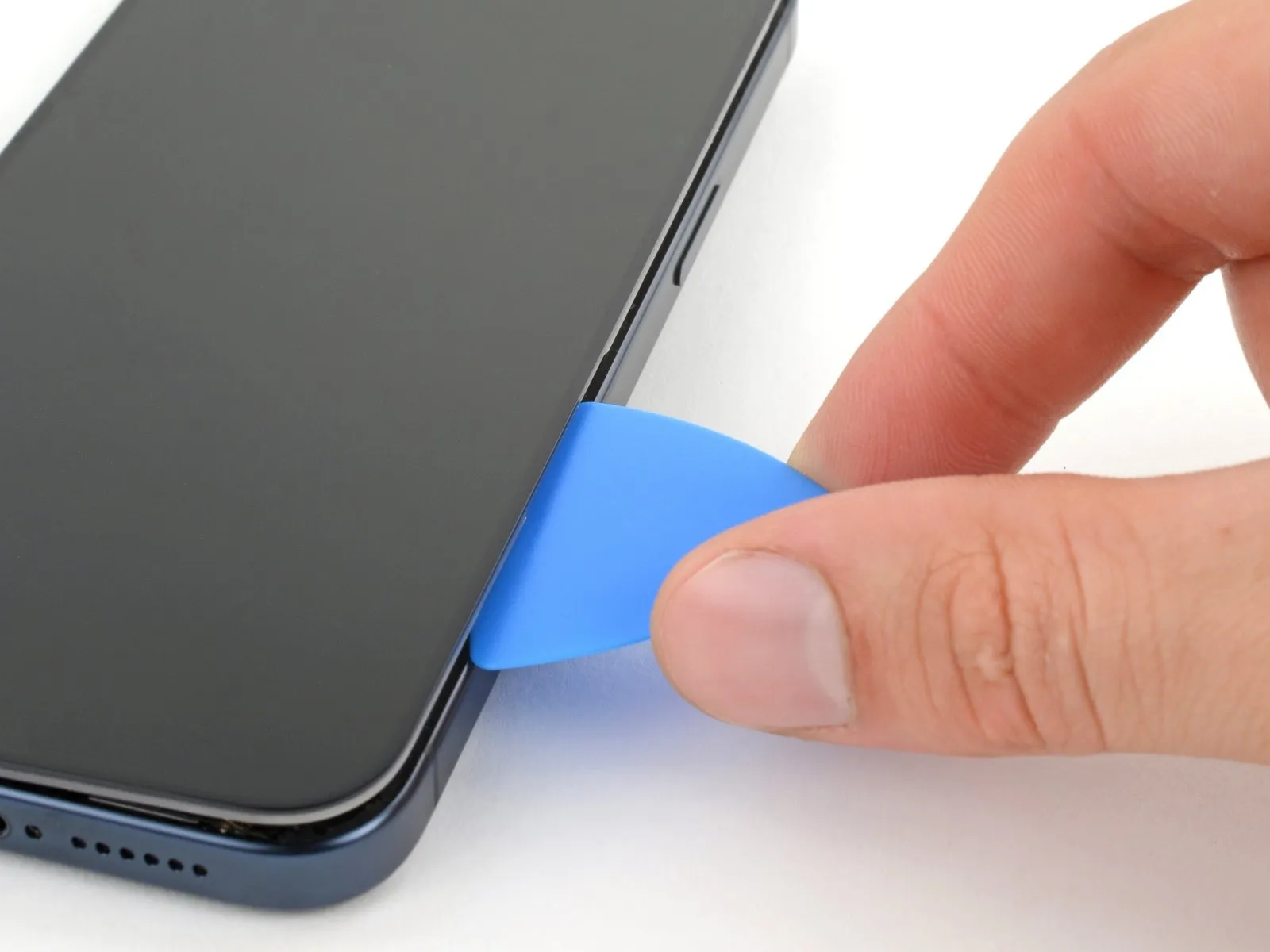
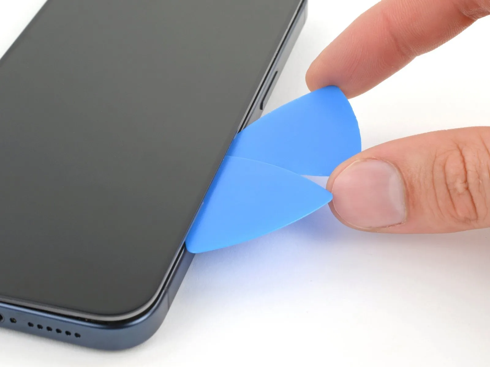
- Twist the pick to increase the gap between the screen and the frame until the right clip releases.
- Insert a second opening pick to the right of the first pick.
Step 13 | Separate the right edge adhesive
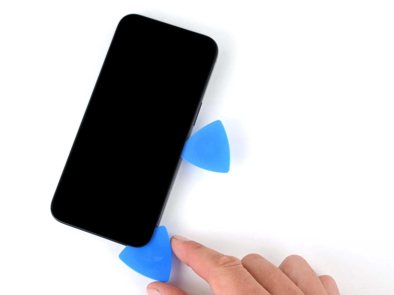
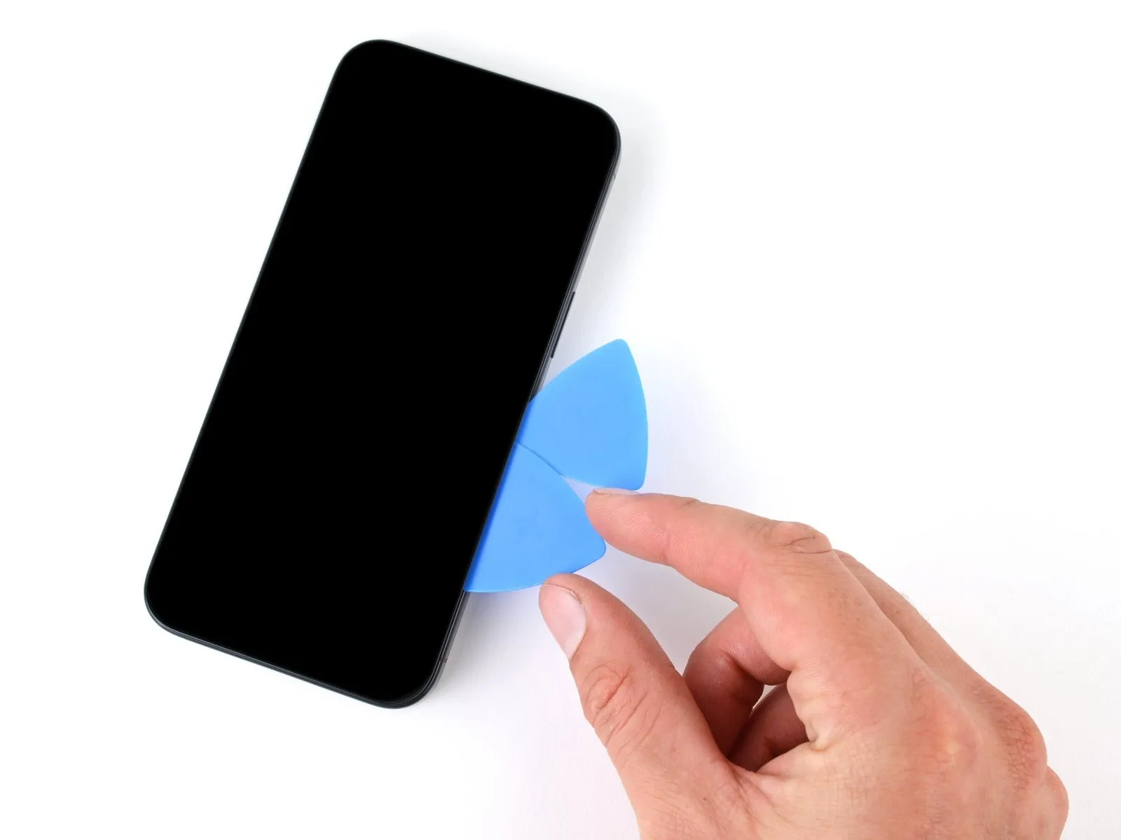
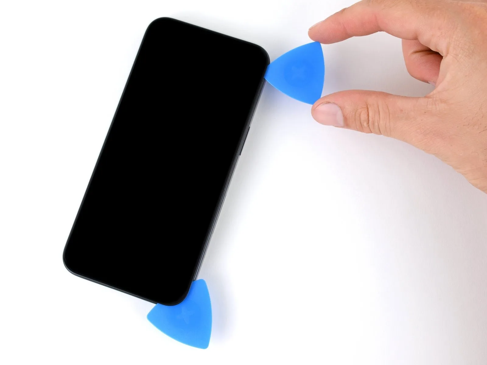
- Slide the first pick back to the bottom right corner of the screen.
- Slide the second pick to the top right corner of the screen to separate the adhesive.
- Leave these picks inserted to prevent the adhesive from resealing.
Step 14 | Heat the top edge
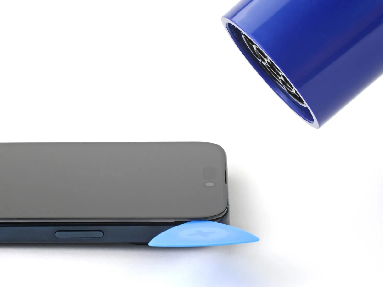
Step 15 | Separate the top edge adhesive


- Don't insert your pick deeper than 3 mm along the top edge.
- Slide your pick around the top right corner and along the top edge to release the two clips and adhesive securing it.
Step 16 | Heat the left edge

Step 17 | Separate the left edge adhesive

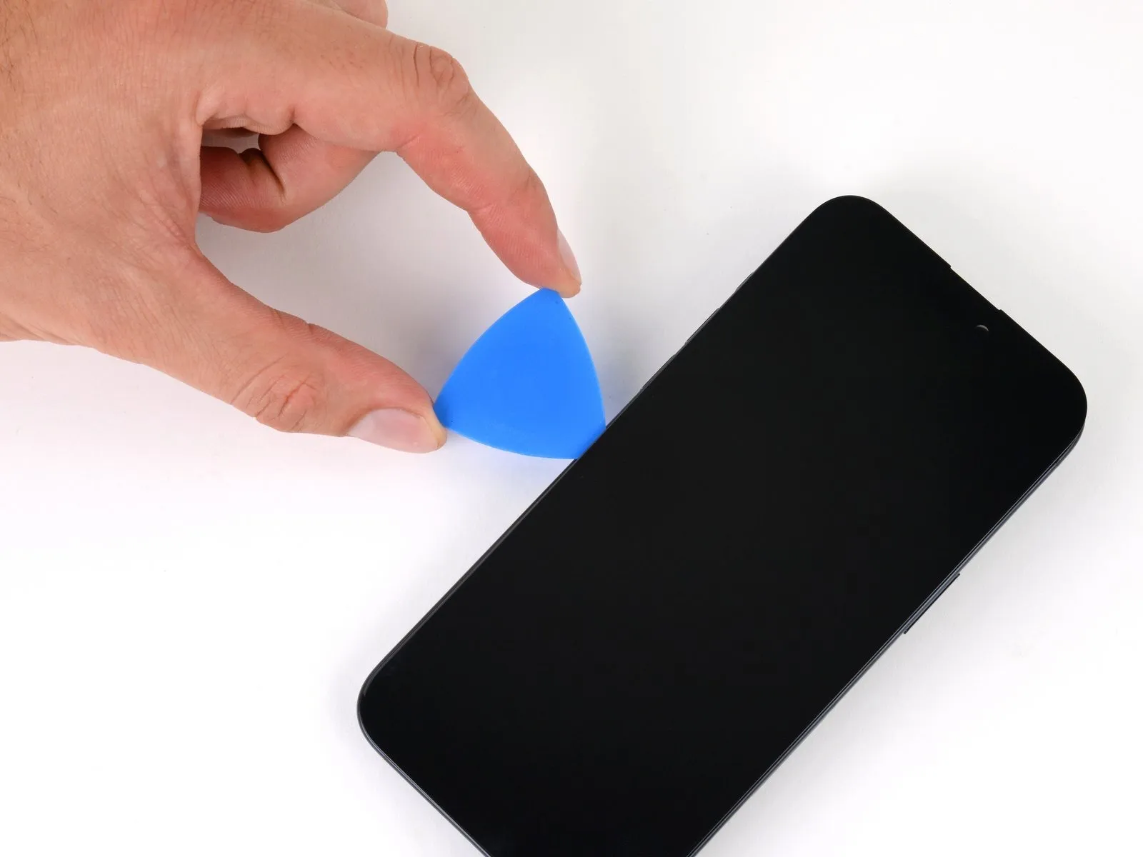

- Don't insert your pick deeper than 2 mm along the left edge to avoid the two cables connecting the screen to the phone.
- Rotate your pick around the top left corner of the screen.
- Slide your pick to the bottom left corner of the screen to separate the adhesive.
Step 18 | Swing open the screen

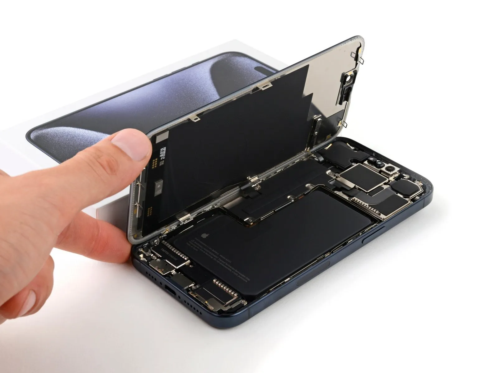
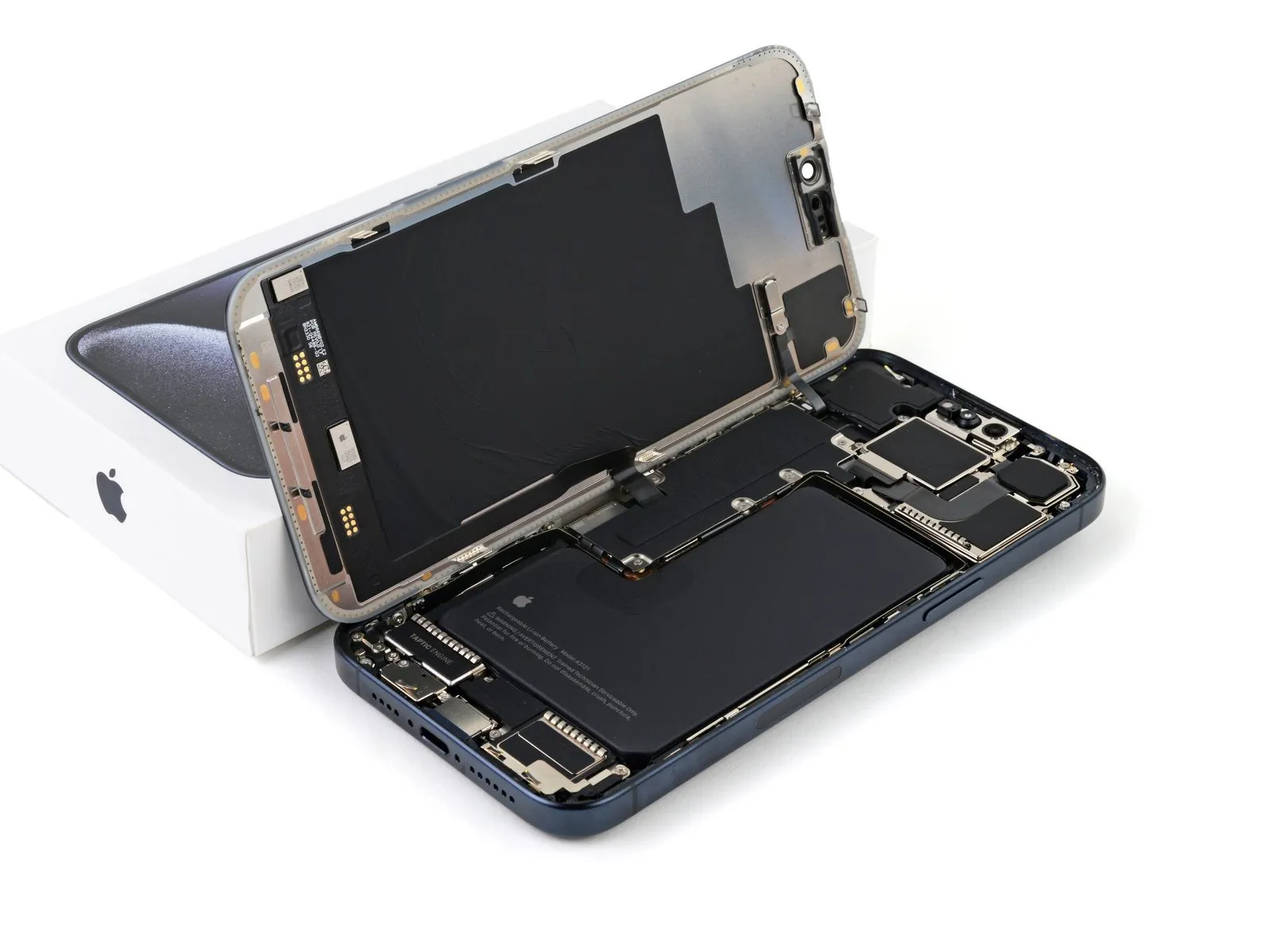
- Gently swing open the screen to the left of the phone.
- If the screen feels stuck, go back around the perimeter to check for missed sections of adhesive or stuck clips.
- Rest the screen against a box or similar object so it doesn't strain the cables.
Step 19 | Unfasten the logic board cover

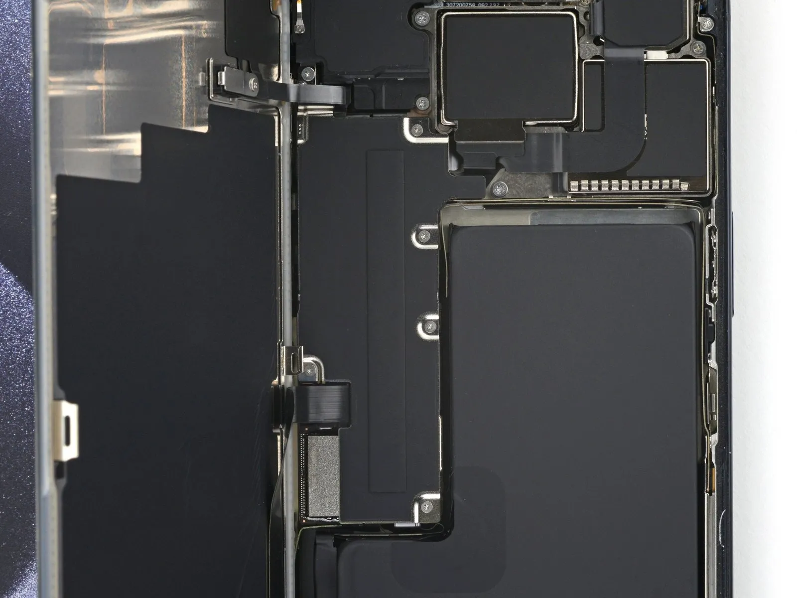
Throughout this repair, keep track of each screw and make sure it goes back exactly where it came from.
Use a tri-point Y000 driver to remove the six screws securing the logic board cover:
- One 2.1 mm-long screw
- Five 1.5 mm-long screws
Step 20 | Remove the logic board cover

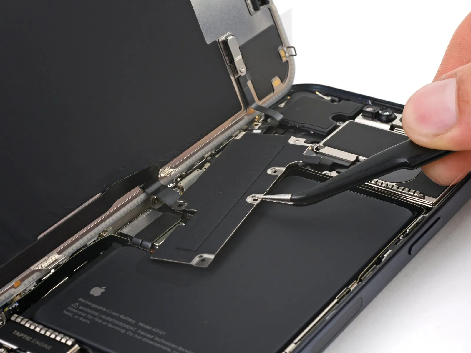
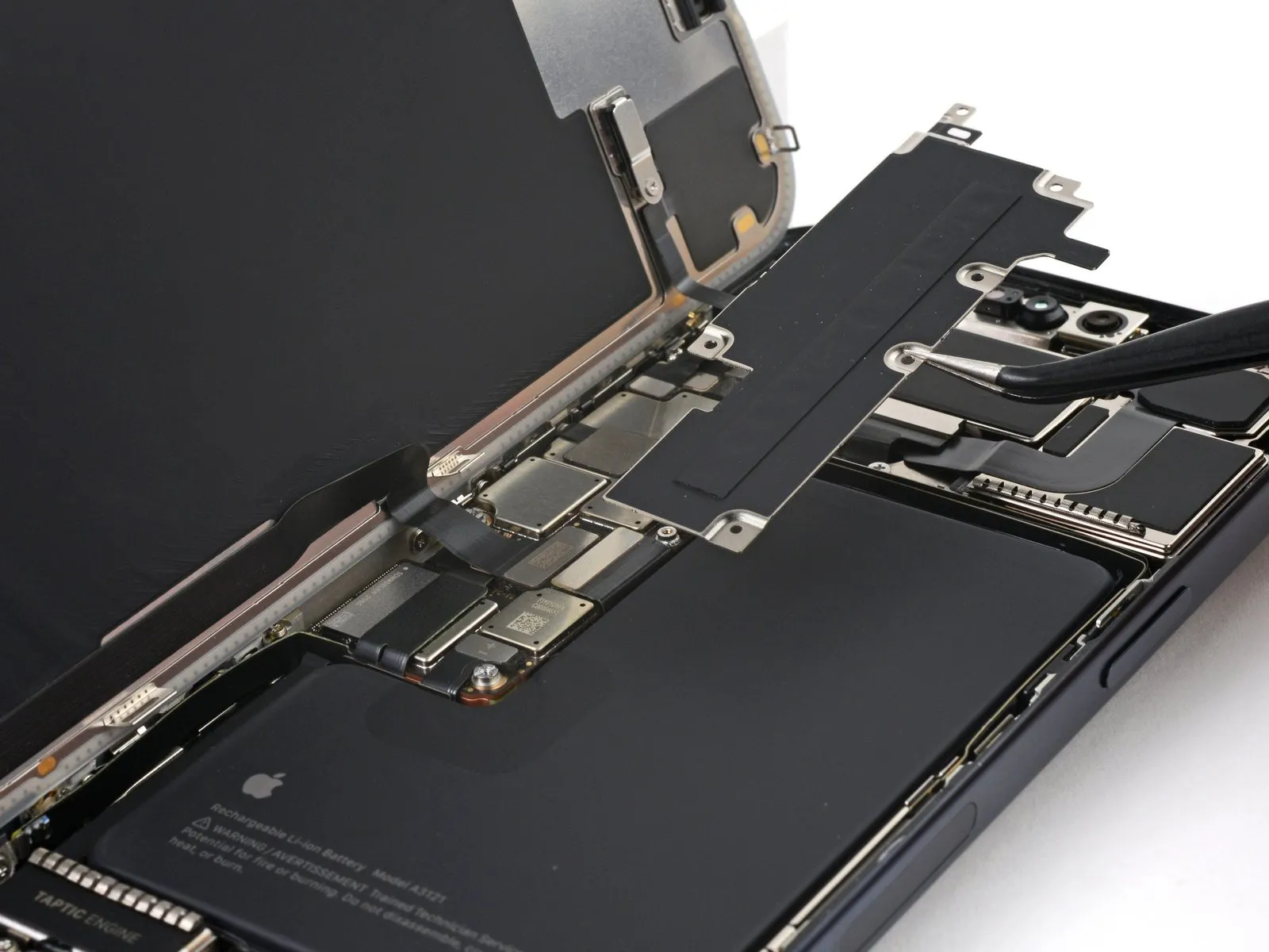
Use tweezers or your fingers to grab and slide the logic board cover toward the bottom of the phone to clear the sensor cable.
Remove the cover.
Step 21 | Disconnect the battery

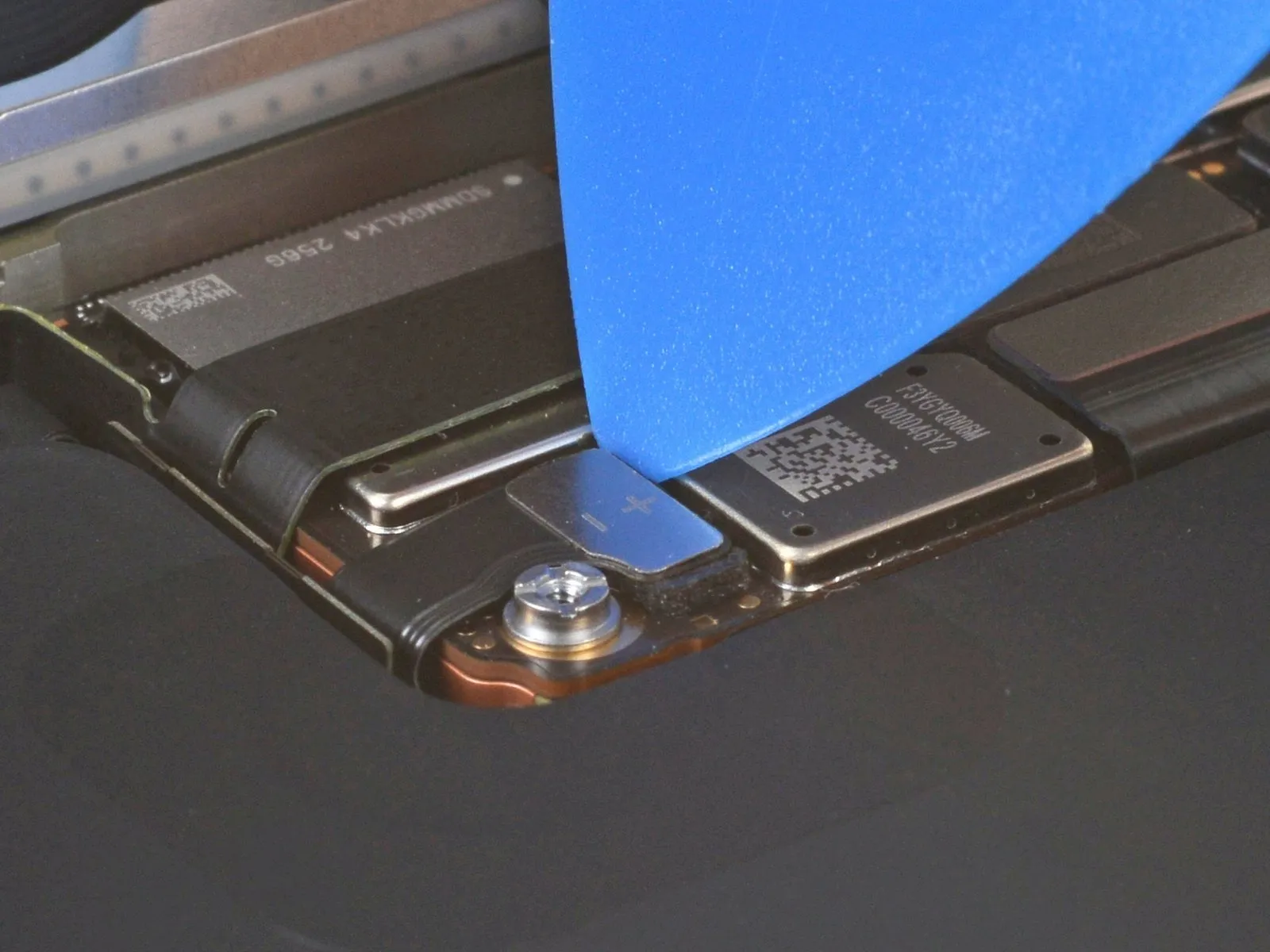
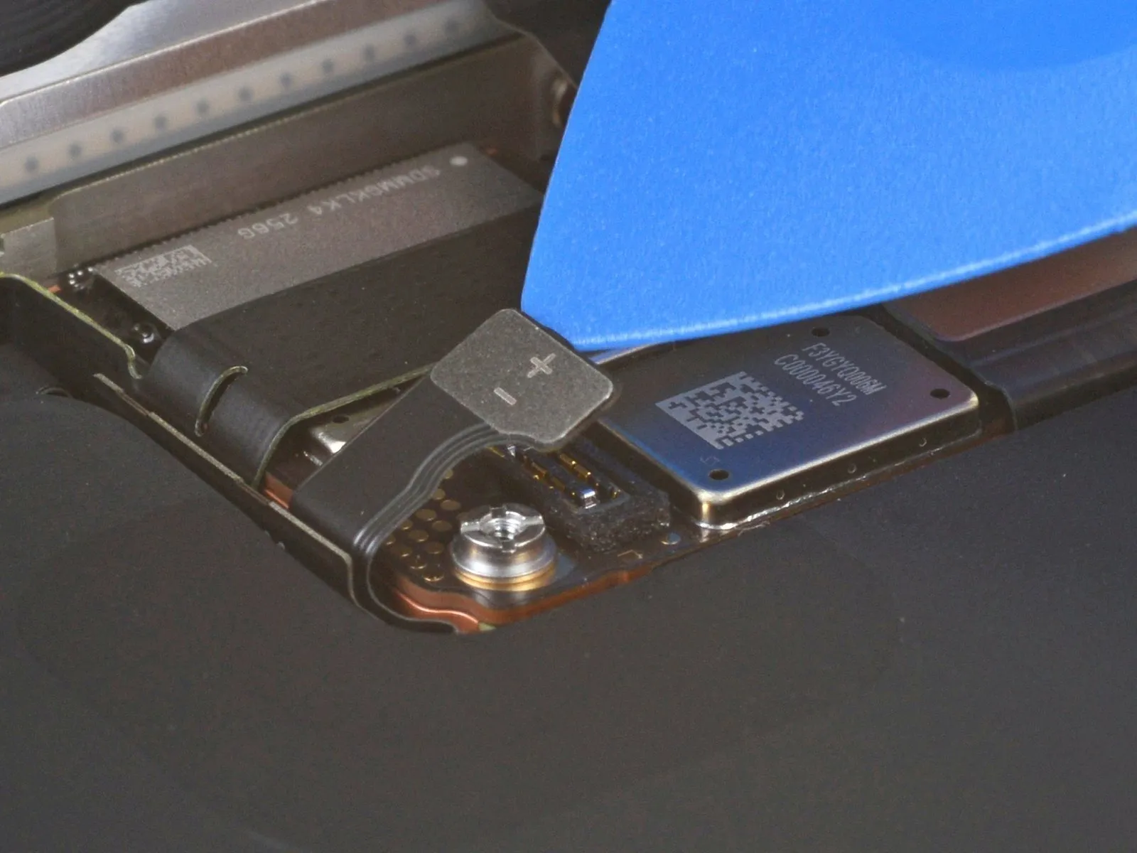
- Use the tip of an opening pick to pry up and disconnect the battery press connector.
- To reconnect a press connector, align it over its socket and gently press down on one side until it clicks into place, then press down on the other side. Make sure it sits flat, as the insulating rubber around the sockets might prevent it from connecting fully.
Step 22 | Disconnect the ambient light sensor
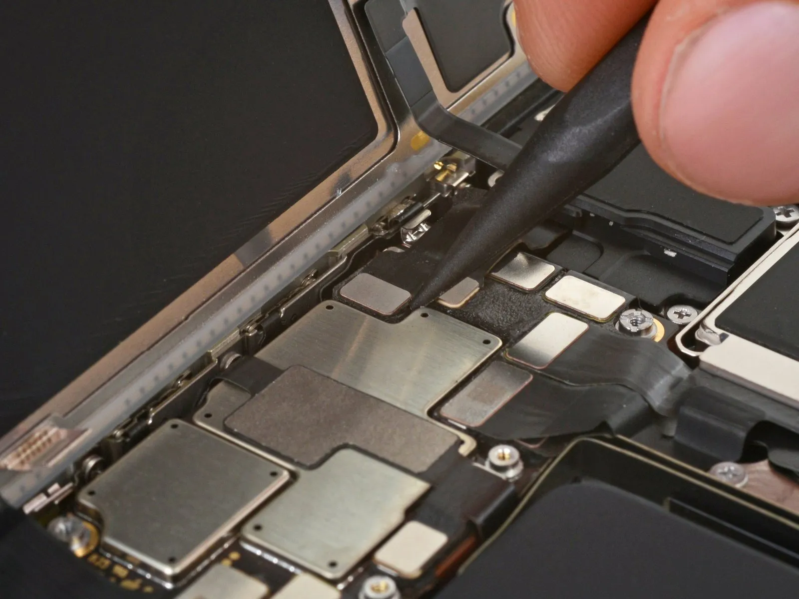
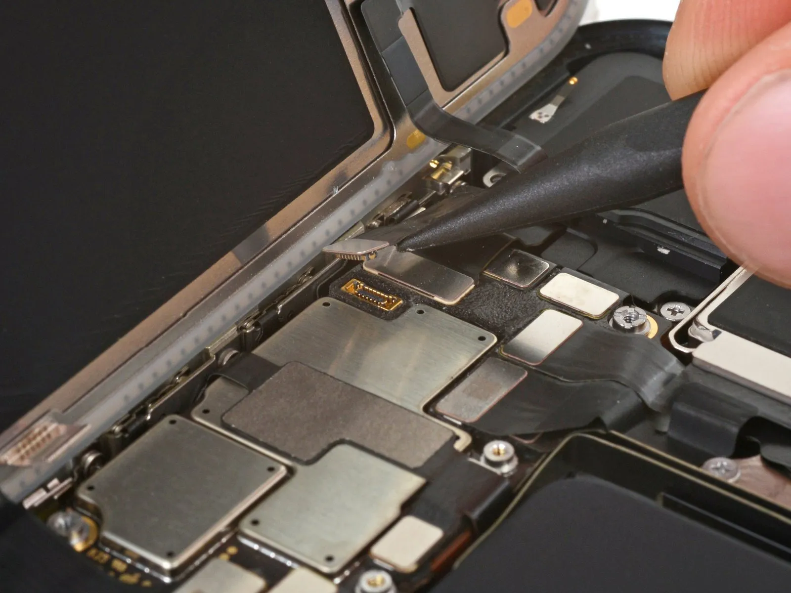
- Use the point of a spudger to pry up and disconnect the ambient light sensor press connector from the top left of the logic board.
Step 23 | Disconnect the screen

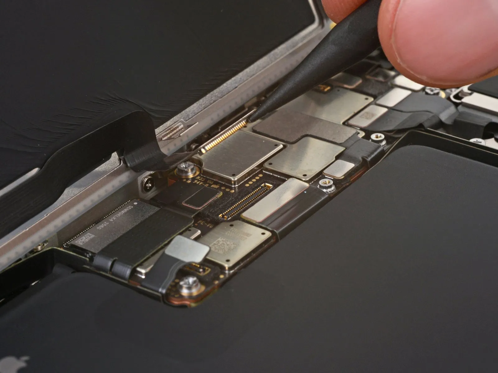
- Disconnect the screen press connector.
Step 24 | Remove the screen
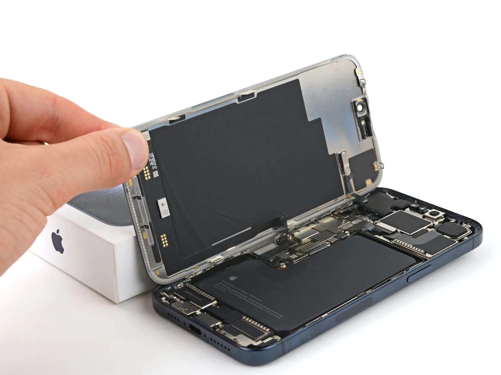
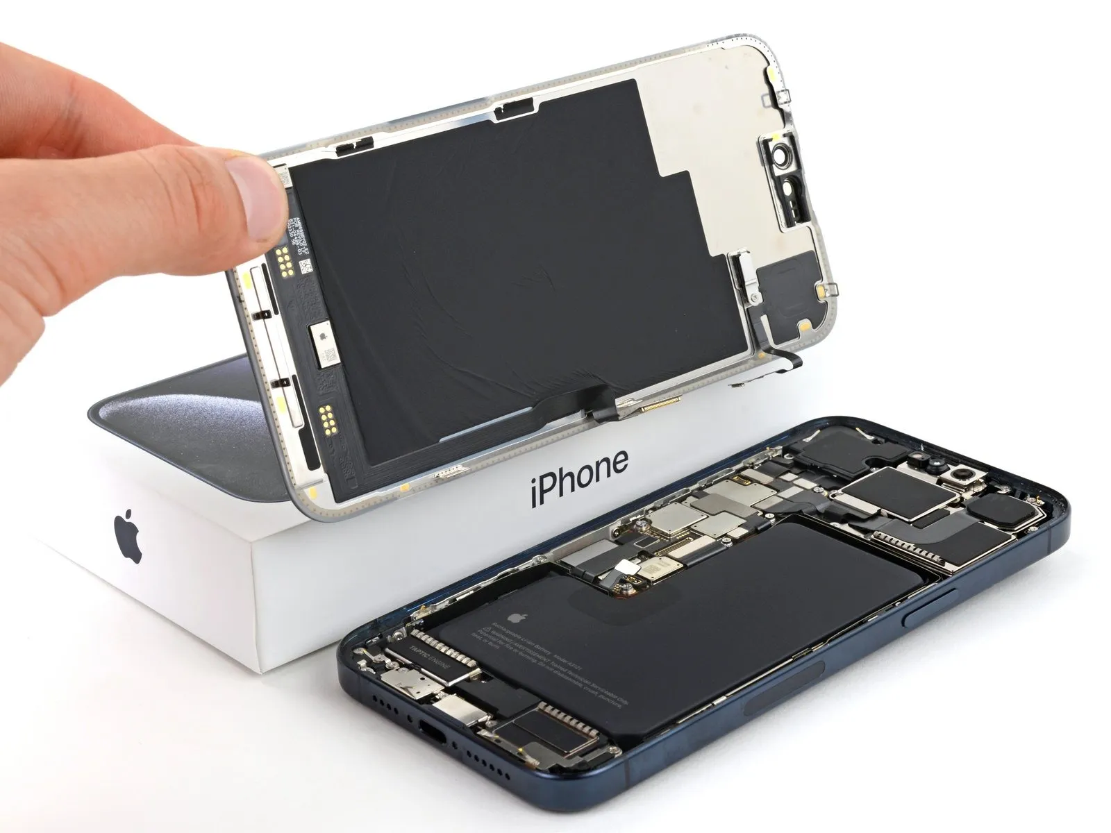
- Remove the screen.
During reassembly, stop here and use this guide to install new screen adhesive. - Be careful not to damage any of the spring contacts as you clean the frame.
Step 25 | Ambient light sensor information


- Check if your new screen comes with an ambient light sensor installed.
- If it doesn't, follow the remaining steps to remove and transfer the sensor from your original screen to your replacement.
Step 26 | Remove the ambient light sensor cover screw

Step 27 | Remove the ambient light sensor cover


- Use tweezers or your fingers to unlatch the ambient light sensor cover and remove it.
- During reassembly, make sure to hook the latch into the small groove on the left side of the black plastic enclosure.
Step 28 | Heat the ambient light sensor adhesive

Use a hair dryer or heat gun to heat the ambient light sensor until it's warm to the touch.
Step 29 | Pry up the sensor


- Be very gentle handing the ambient light sensor, as its cable is extremely fragile and thin. Avoid using your tool in the direction of the cable.
- Use the tip of an opening pick to pry up the edge of the ambient light sensor out of its black plastic enclosure.
- This may be tricky. The enclosure prevents you from inserting a tool underneath the sensor. Try from a couple angles, if your tool tends to slip.
Step 30 | Reheat the ambient light sensor

Step 31 | Separate the adhesive


- Insert the tip of your opening pick underneath the press connector cable.
- Slide your pick back and forth underneath both cables to separate the lower section of adhesive.
Step 32


- Be careful not to sharply crease or tear the ambient light sensor.
- Reheat the glued down section of the component at any point if the adhesive cools and becomes stubborn to cut.
- Use the flat end of your pick to slide back and forth underneath the sensor until you've separated roughly half of it from the screen.
Step 33 | Remove the ambient light sensor


- Use your fingers to grab the raised half of the sensor and peel it from the screen.