iPhone 16 Pro LiDAR Sensor Replacement
This document details the procedure for substituting the Lidar Sensor within an iPhone 16 Pro.The Lidar Sensor, a critical component for depth perception, is the focus of this replacement process.Upon finishing the outlined steps, it is essential to perform calibration of a genuine Apple Lidar Sensor utilizing the Repair Assistant application.
Successful completion of this repair necessitates the use of fresh replacement back glass adhesive to ensure proper sealing and structural integrity.To ensure accurate functionality, a genuine Apple Lidar Sensor must be employed during the calibration phase.Proper adhesion of the rear enclosure is guaranteed by installing new replacement back glass adhesive.
- The repair process involves the direct substitution of the Lidar Sensor module located within the iPhone 16 Pro.
Step 1 | Prepare the phone for disassembly


- To mitigate safety risks associated with fully charged lithium-ion batteries, permit the phone's power source to deplete to a level below 25 percent.Disconnect all connected wires and cords from the device before proceeding.Simultaneously press and maintain the power button alongside one of the volume buttons, then utilize the sliding mechanism to deactivate the phone's operation.
- A fully charged lithium-ion battery presents a potential safety concern, necessitating a partial discharge before repair.
- Deactivation of the device requires a simultaneous press of the power button and a volume button, followed by a slide action to cut power.
Step 2 | Tape over any cracks
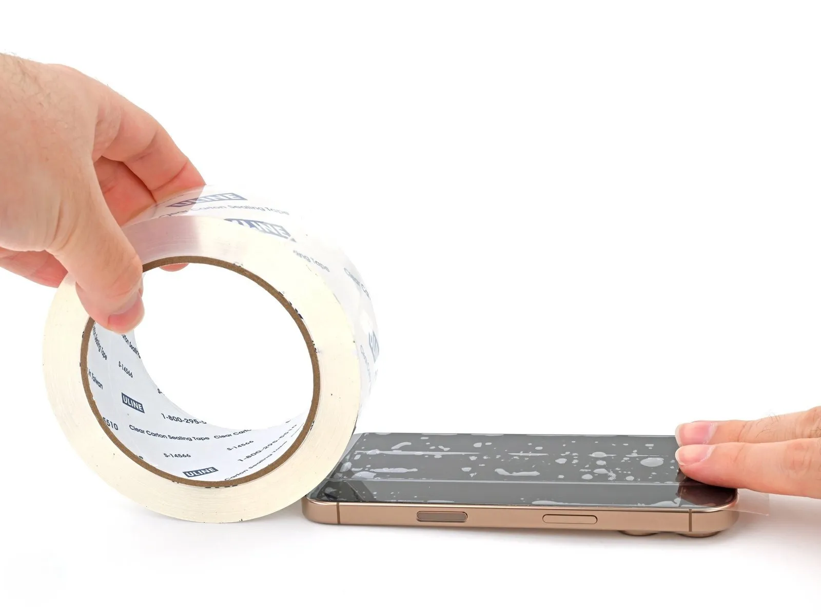
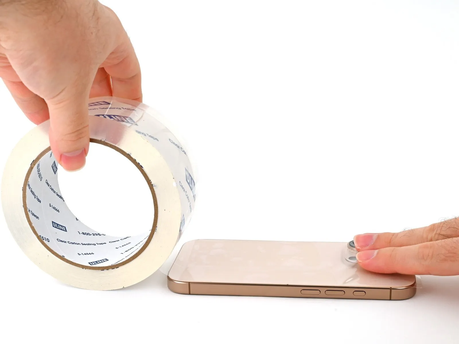
- To prevent injury and simplify the subsequent dismantling process when the display or rear glass exhibits severe cracking, apply multiple layers of adhesive packing tape across the fractured surfaces.
- Confirm the presence of a sufficiently sized, uninterrupted surface region proximate to the lower edge, ensuring it provides adequate adhesion for a suction cup.
Step 3 | Mark your opening picks


- Excessive insertion of a prying tool carries a risk of device damage; implement the following procedure to safeguard against this by marking the tool.
- Using a precise measuring tool, determine a distance of3 mmfrom the tool's distal end and clearly indicate this measurement on the prying tool with a permanent marking instrument.
- For enhanced precision, consider applying distinct markings to the tool's other corners, each representing a different measurement.
- As an alternative method, affix a coin to the prying tool's shaft, positioning it3 mmfrom the tip to serve as a visual depth guide.
Step 4 | Remove the pentalobe screws
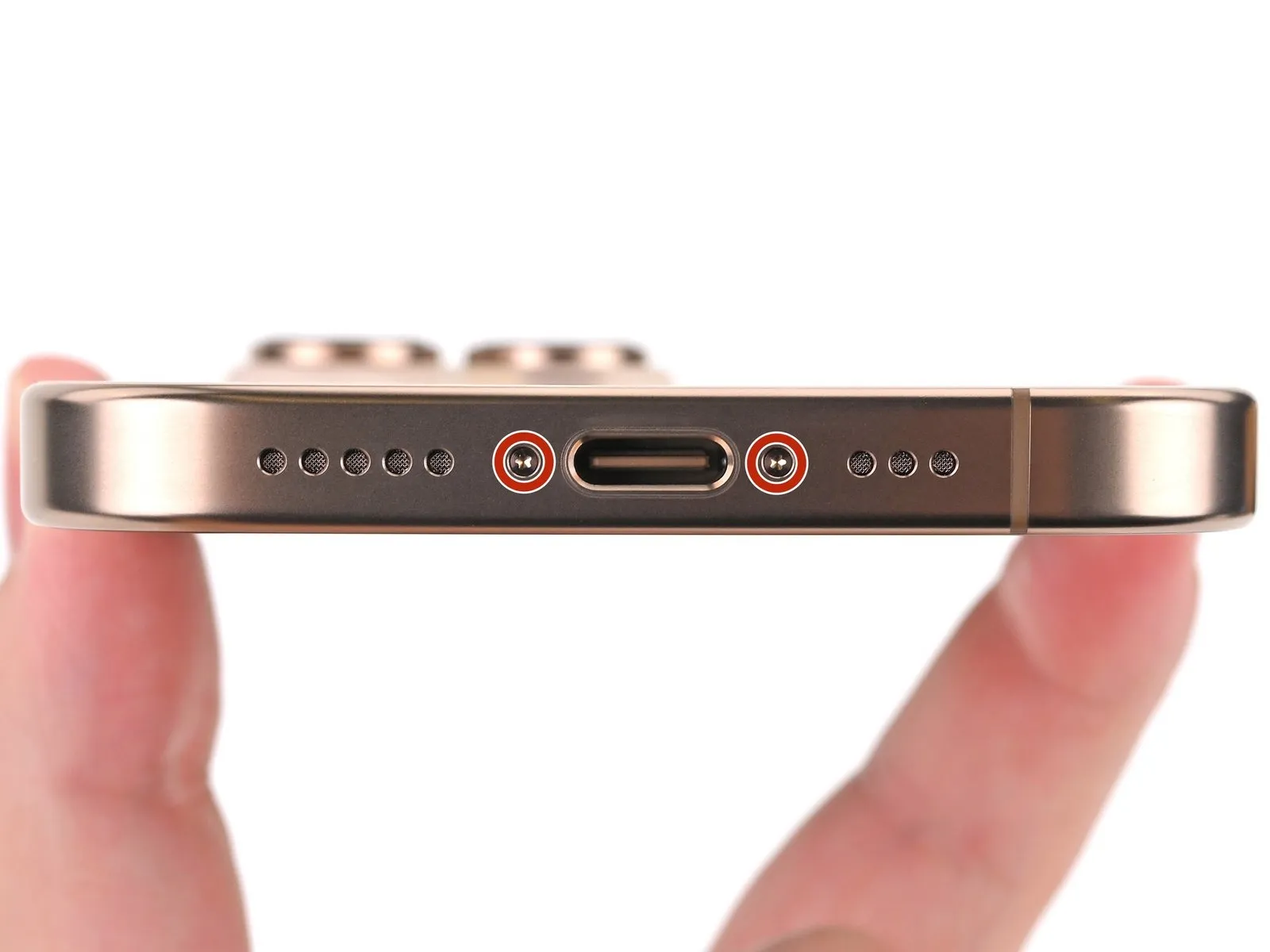

Employ a P2 pentalobe screwdriver for detaching the two screws, each measuring 7.4 millimeters in length, located on both sides of the USB-C connector.The screws securing the device near the USB-C port require removal utilizing a P2 pentalobe screwdriver.Two screws, with a length of 7.4 mm, are affixed to each side of the USB-C port and necessitate removal via a P2 pentalobe screwdriver.
Step 5 | Heat the bottom edge
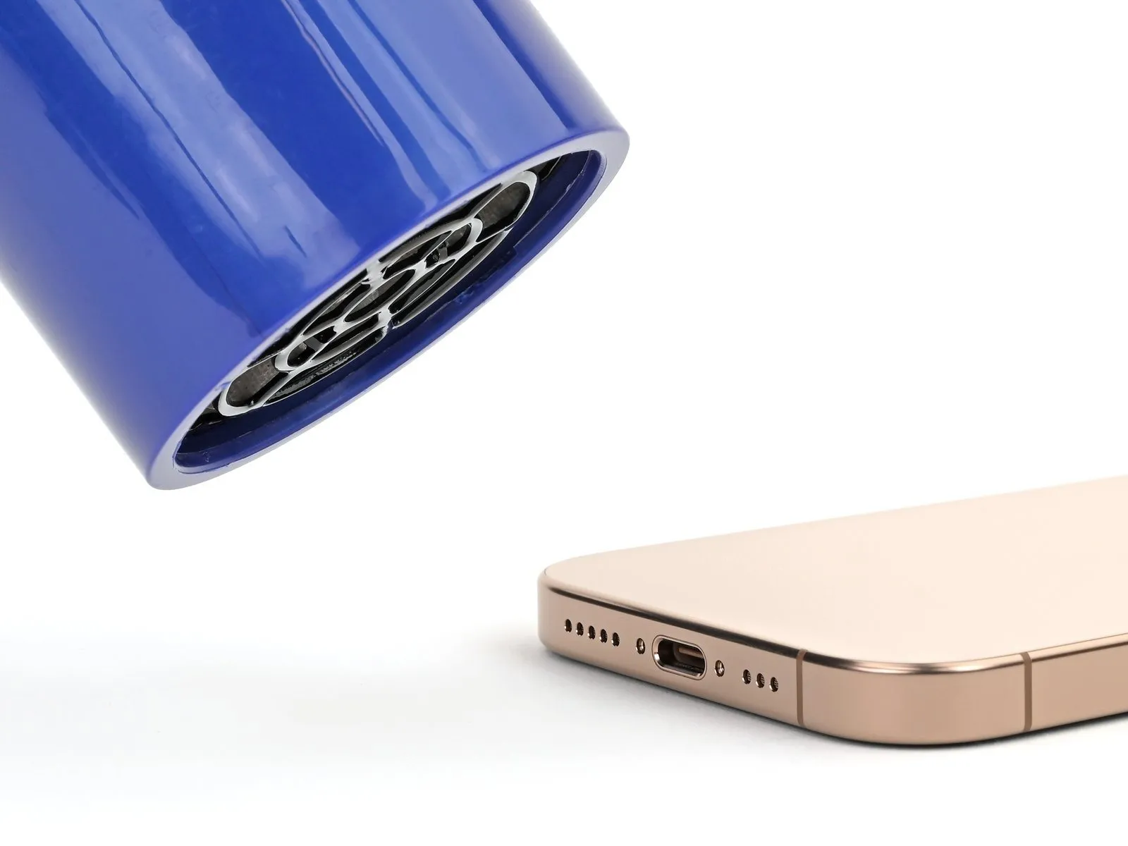
- Utilize a heated iOpener, or a similar device, on the lower perimeter of the rear glass panel, maintaining the heat for a duration of two minutes.As an alternative method, a hairdryer or heat gun can be employed to warm the lower edge of the back glass until it reaches a comfortably warm temperature.Exercise caution to prevent overheating the device; the internal battery is vulnerable to thermal degradation.
- The maximum safe temperature for the device is determined by the sensation of warmth when touched.
- Prolonged or excessive heat exposure may compromise the integrity and lifespan of the battery.
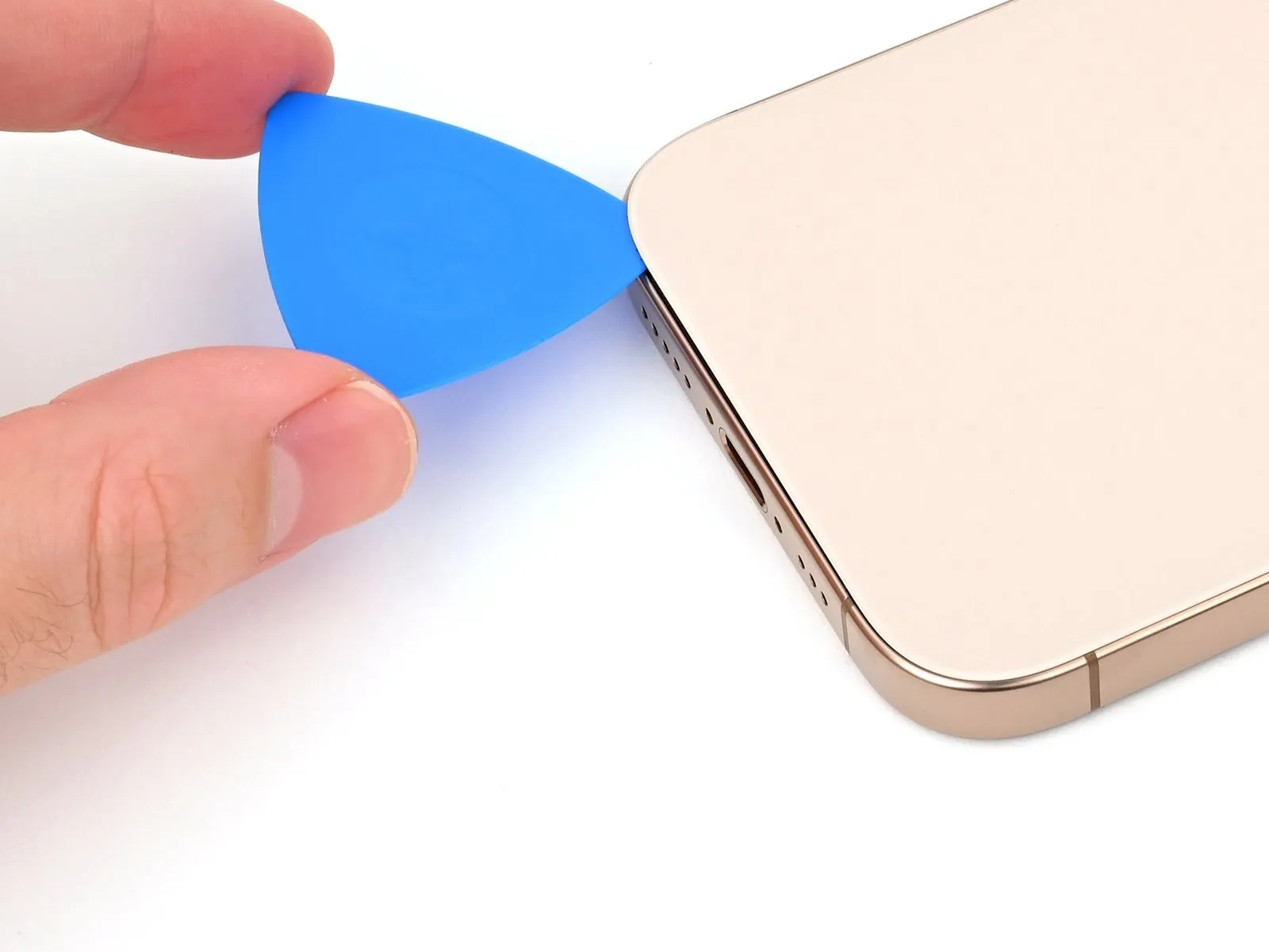
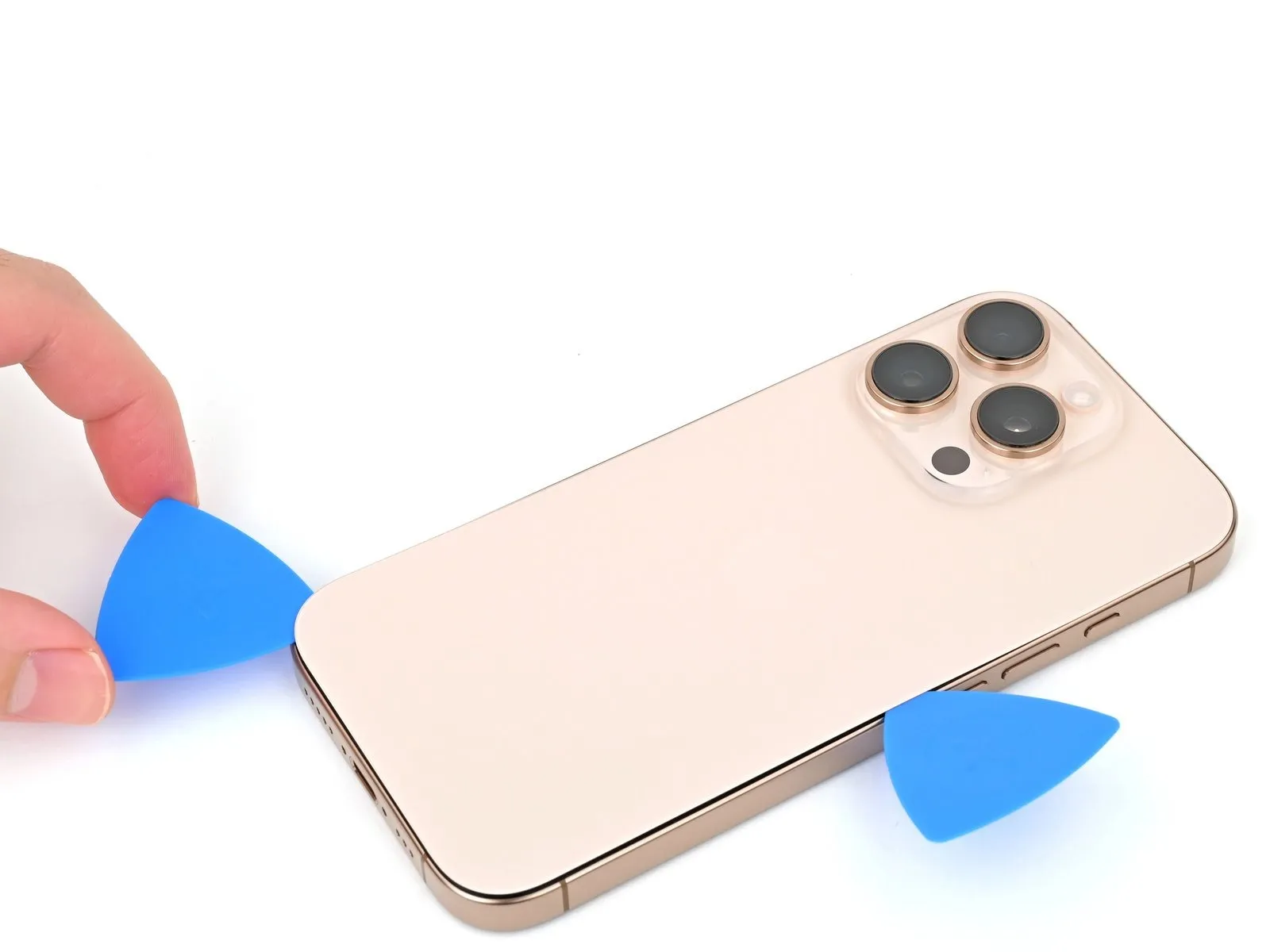
Step 6 | Insert an opening pick
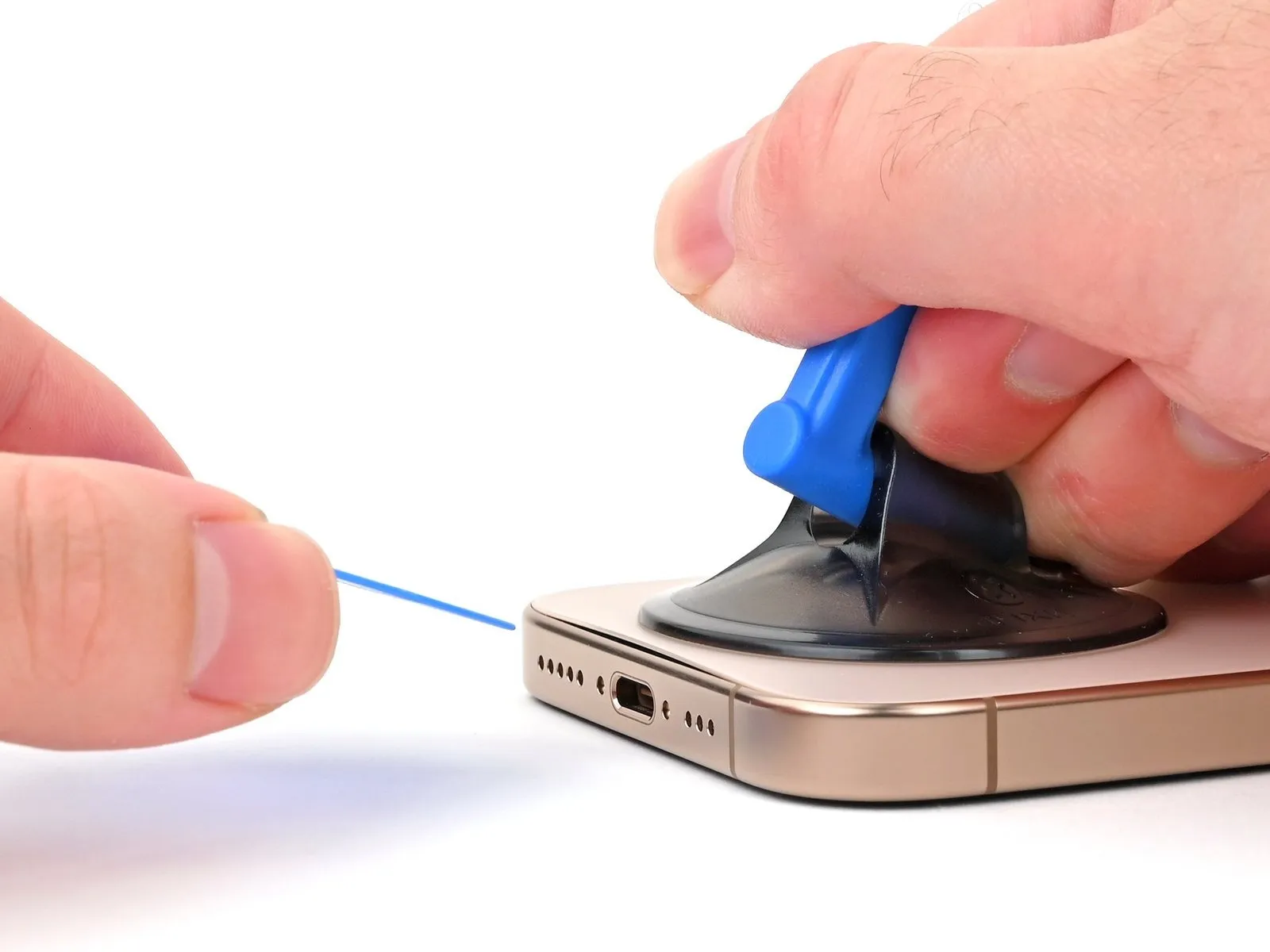
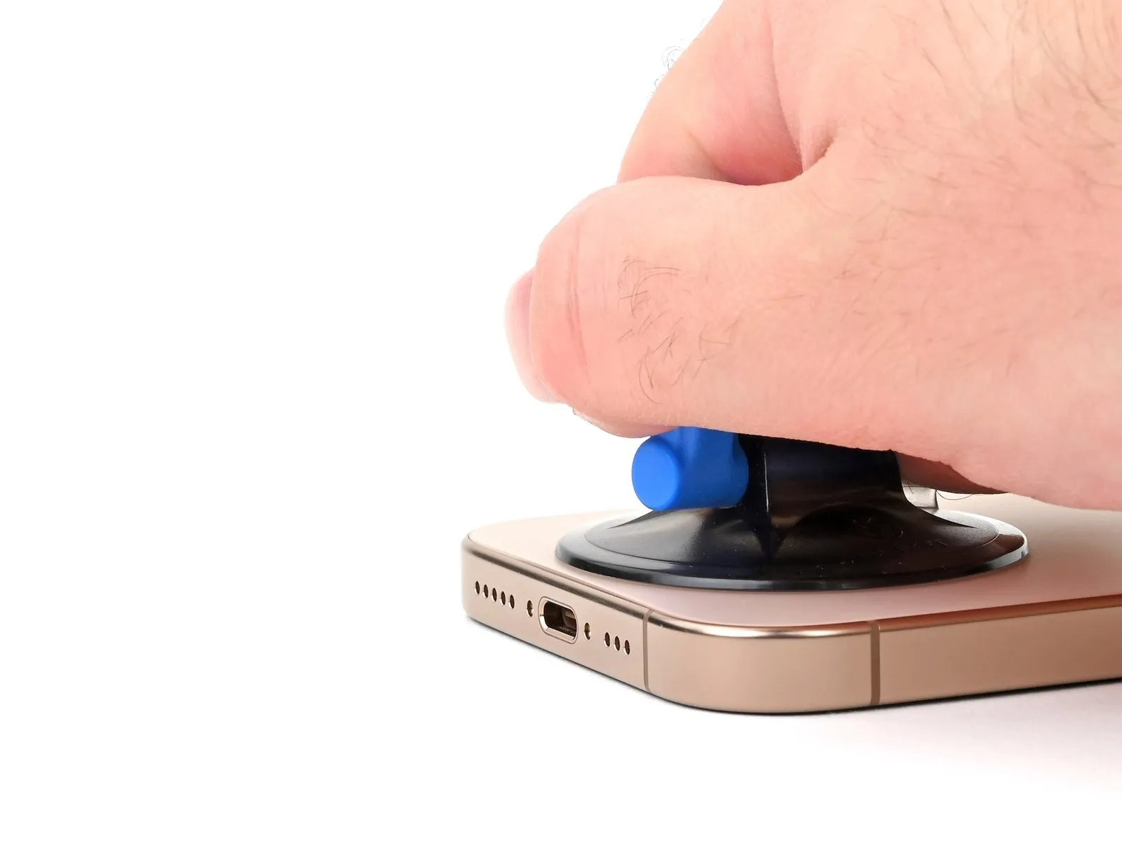

- Securely attach a suction cup to the lower perimeter of the rear glass, positioned directly over the USB-C connector.
Exert a consistent and considerable upward pull on the suction cup to generate separation between the rear glass and the device's structural frame.
Carefully introduce the pointed end of a prying tool into the newly formed space.
Step 7 | Back glass information
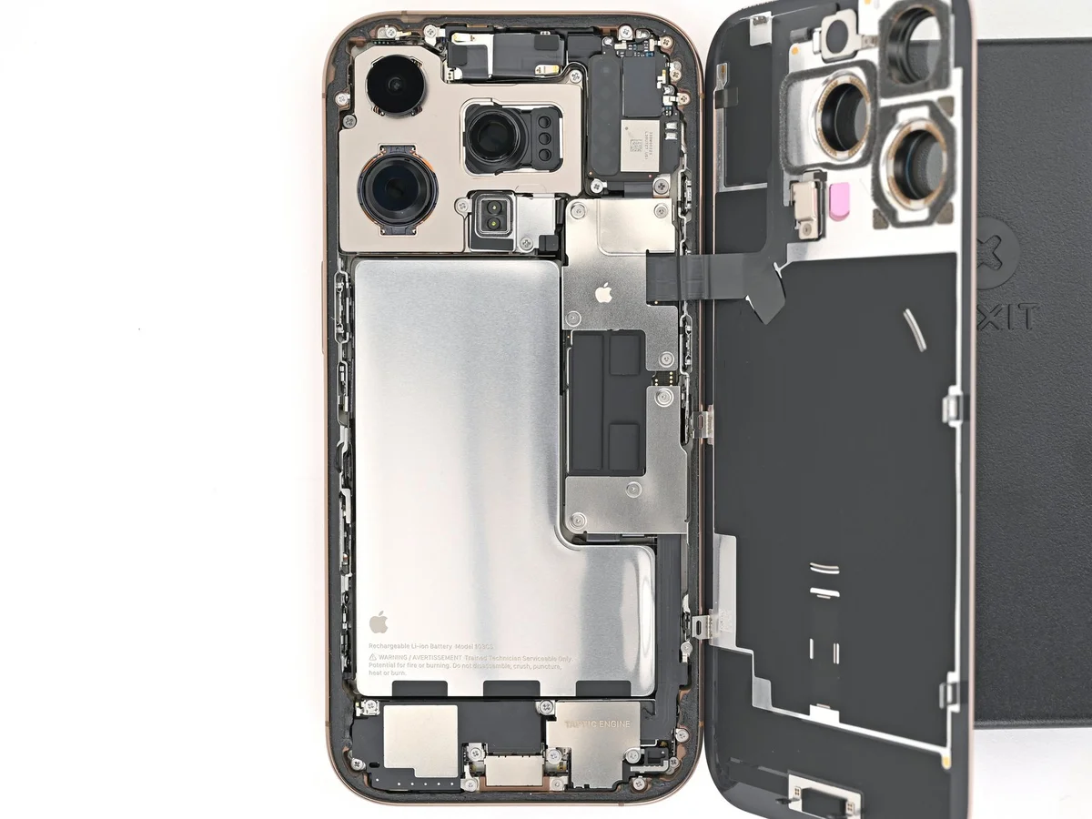
- During the process of separating the rear glass with a separating tool in subsequent procedures, exercise caution regarding specific regions.
A fragile cable, linking the rear glass assembly to the device's internal components, is situated near the volume up button; therefore, prevent tool insertion in this area to prevent cable damage.
Numerous spring contacts are positioned along the phone's edges; therefore, restrict tool insertion depth as instructed in each step to prevent deformation of these contacts.
Should the spring contacts become damaged, carefully reposition them using a spudger or opening pick to ensure proper alignment with the gold contact pads on the rear glass.
Step 8 | Separate the bottom edge adhesive

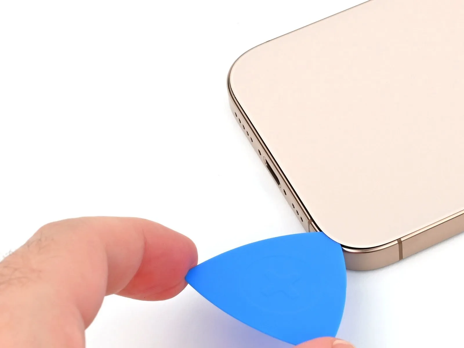
To prevent potential damage to the spring contact, ensure the pick's insertion depth does not exceed 5 millimeters along the lower edge.Employ a reciprocating motion, sliding the pick along the lower edge, to effectively release the adhesive bond.Maintain the pick's position within the lower-right corner to inhibit the adhesive from re-adhering.
Adhesive separation is achieved through a back-and-forth movement of the pick along the bottom edge.
A maximum insertion depth of 5 mm must be observed on the bottom edge to safeguard the spring contact's integrity.
Step 9 | Heat the right edge

Apply warmth to the right-hand perimeter of the rear glass panel, continuing until surface temperature is sufficient for tactile perception.Elevate the temperature of the back glass's right side to a point where it can be felt as warm by touch.
Step 10 | Separate the bottom right corner adhesive
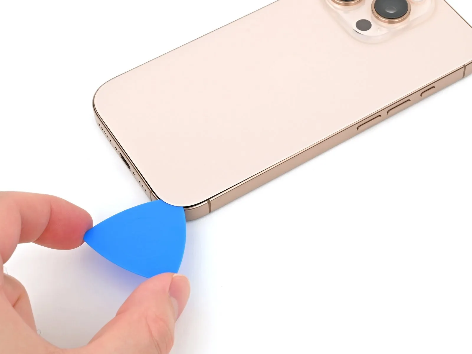

- Employ a prying tool to maneuver along the lower-right perimeter and ascend the right side to a midpoint, recognizing the resistance of a retaining clip that fastens the rear glass assembly.
Exercise caution and avoid cutting in the vicinity of the volume controls, as doing so risks compromising the wireless charging and flash illumination cable.
Maintain the pick's position within the separation to inhibit the adhesive layer from reforming.
Step 11 | Heat the left edge

Apply warmth to the left side of the rear glass panel, ensuring it reaches a temperature comfortable to the hand.Elevate the temperature of the back glass's left border to a point where it can be felt as warm to the touch.
Step 12 | Separate the left edge adhesive

- Introduce a supplementary opening tool into the gap located at the device's lower boundary.
Maneuver the second tool around the lower-left corner, proceeding along the screen's left side to detach the adhesive and disengage the metal fasteners.
Audible and tactile confirmation of the metal clip release will occur during their separation.
Maintain the position of the initial tool at the upper-left corner to inhibit adhesive re-bonding.
Step 13 | Heat the top edge

Step 14 | Separate the top edge adhesive


- To prevent harm to the spring contacts, ensure the insertion depth of your tool remains no greater than 3 millimeters along the upper perimeter.Employing a sliding motion, guide your opening tool along the top edge, progressing around the upper-right corner toward the volume up button, to sever the adhesive bond.The release of the upper two retaining clips will be accompanied by audible and tactile clicks, indicating successful separation.
- These clicks signify the disengagement of the clips as the adhesive is parted.
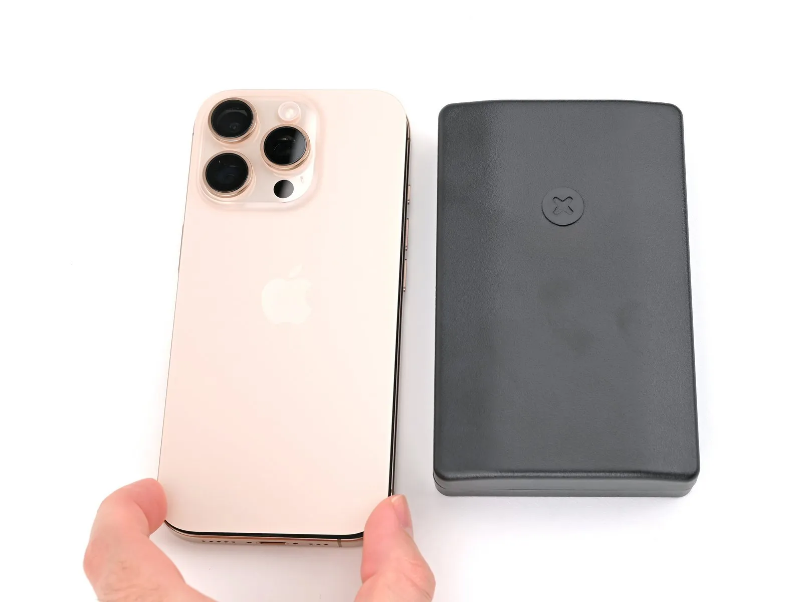
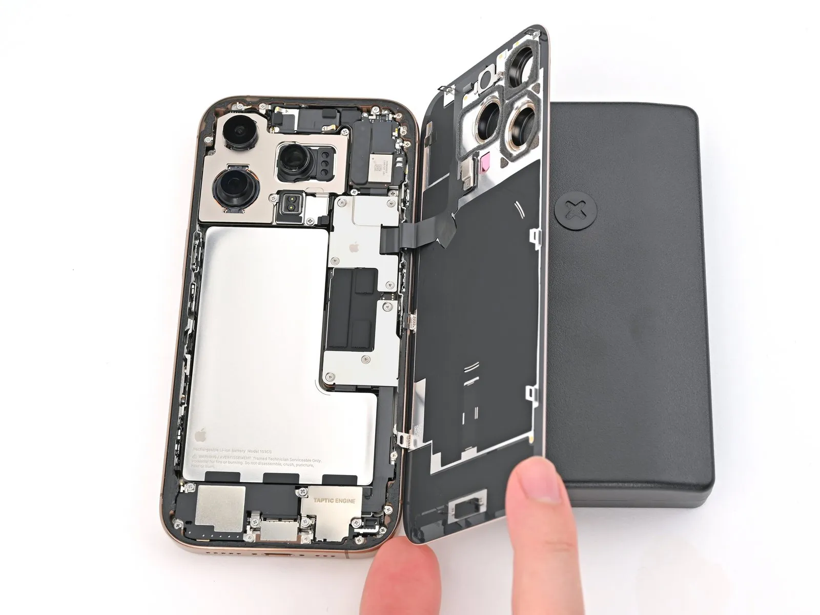
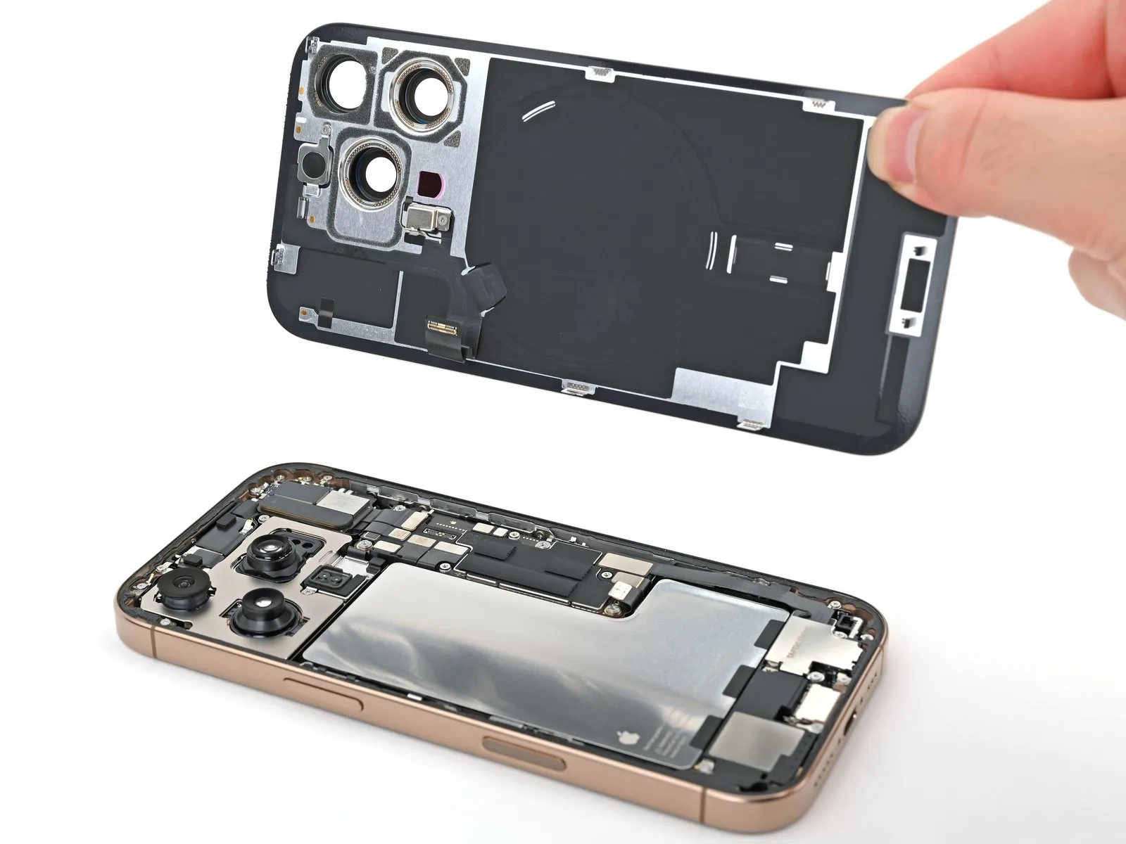
Step 15 | Swing open the back glass
- Refrain from completely detaching the rear glass panel at this stage, as it remains connected via a fragile ribbon cable; proceed with the subsequent instructions to ensure safe removal.
- Should the rear glass panel resist easy pivoting, avoid applying excessive force; instead, re-examine the edges with your tool to identify any remaining adhesive or obstructed clips.
- It might be necessary to elevate the rear glass panel slightly prior to pivoting it open to ensure complete disengagement of the retaining clips.
- Carefully pivot the rear glass panel in the direction of the volume buttons.
- Provide support for the rear glass panel using a stable, non-abrasive object, such as a small box, to prevent stress on the cable.
- Extract the opening tools.
- To safeguard the rear camera lenses during internal servicing, it is advisable to apply polyimide tape; exercise caution and avoid pressure on the lenses to prevent damage to their sensitive stabilization components.
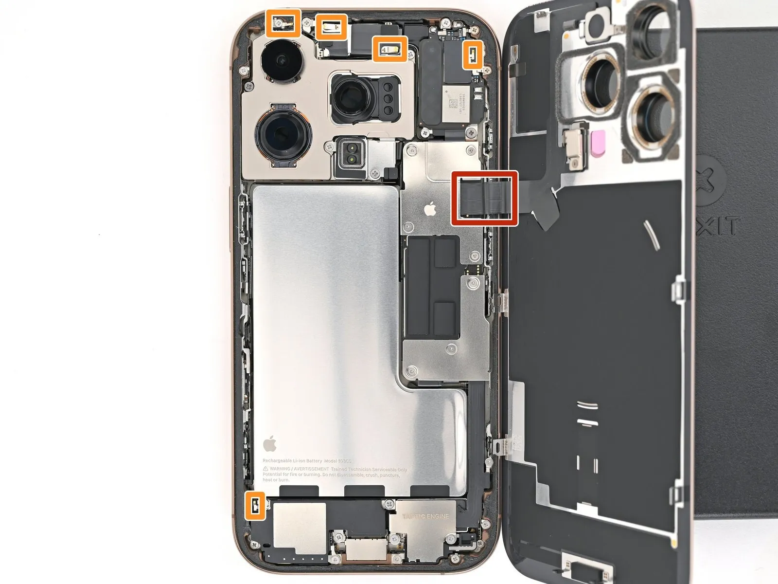
Step 16 | Disconnect the battery
- Employ a tri-point Y000 screwdriver for the task of detaching the lower connector cover's fasteners.The lower connector cover is held in place by three screws that require a tri-point Y000 screwdriver for removal.Three screws, each requiring a tri-point Y000 screwdriver, secure the lower connector cover.
- Two screws, each measuring 1.2 millimeters in length, are used to affix the lower connector cover.The lower connector cover is fastened with two screws, each having a length of 1.2 millimeters.A single screw, with a length of 1.0 millimeters, is also utilized in securing the lower connector cover.
- One screw, specifically 1.0 millimeters in length, contributes to the lower connector cover's attachment.To release the lower connector cover, a tri-point Y000 screwdriver is necessary to unscrew the three securing fasteners.The fasteners holding the lower connector cover consist of two 1.2 mm screws and one 1.0 mm screw, all requiring a tri-point Y000 screwdriver.
Step 17

- Employing either tweezers or direct manual manipulation, detach the lower connector cover.The lower connector cover can be dislodged using tweezers for precision or by carefully grasping it with your fingers.To facilitate removal, a tool such as tweezers or the fingertips can be utilized.Carefully lift and extract the lower connector cover, selecting tweezers or your fingers as the preferred method.For the purpose of removing the lower connector cover, either tweezers or manual finger contact is acceptable.
Step 18
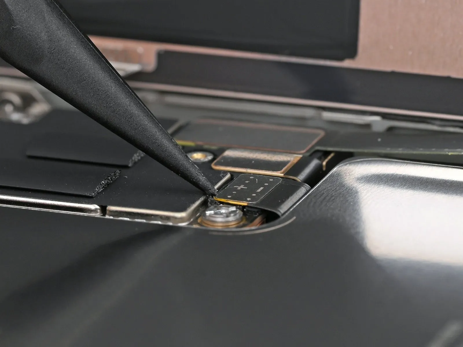
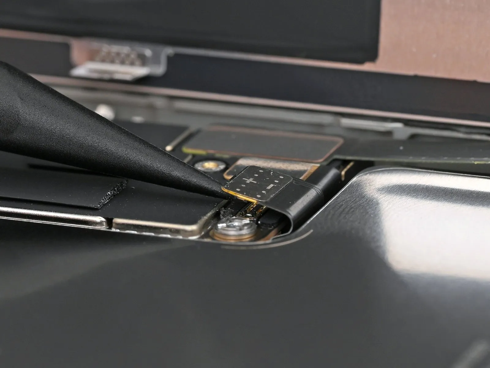
- Employ the tip of a spudger to carefully lift and detach the battery press connector.A spudger's pointed end facilitates the separation of the battery press connector from its socket.To release the battery press connector, apply gentle upward pressure with a spudger.
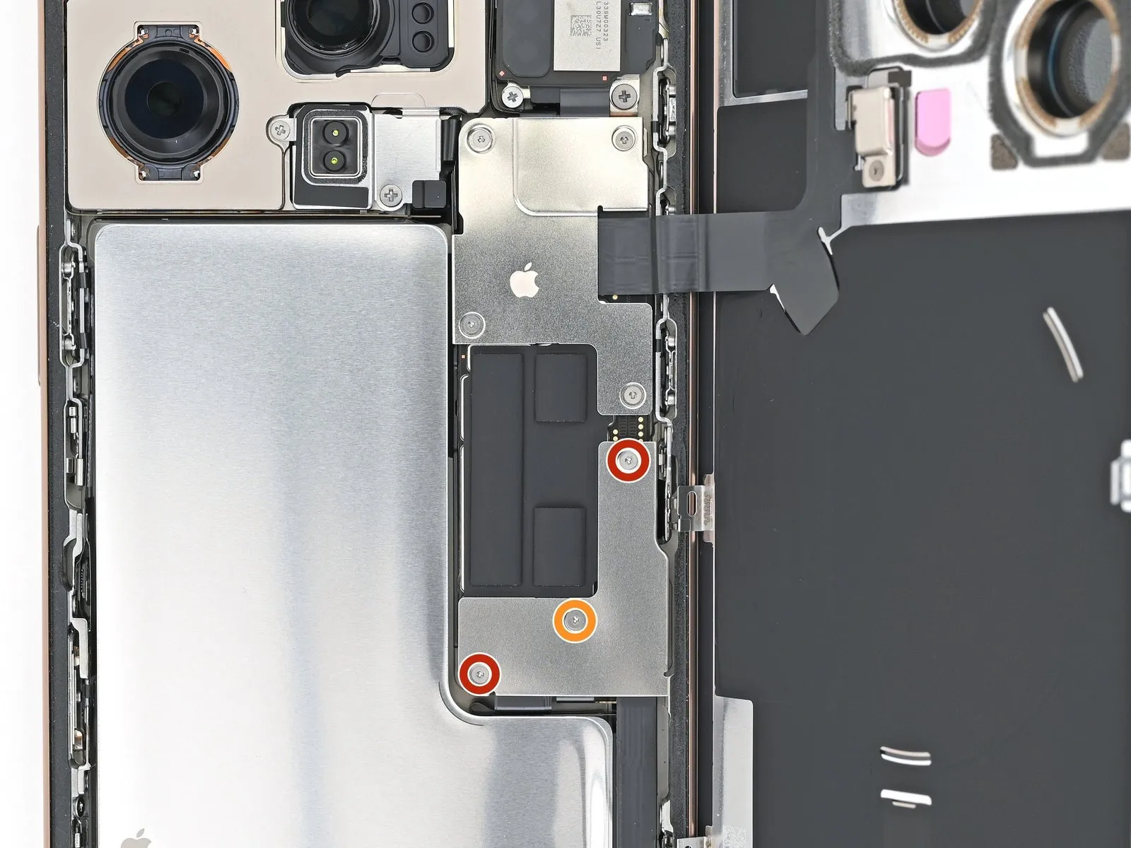
Step 19 | Disconnect the back glass

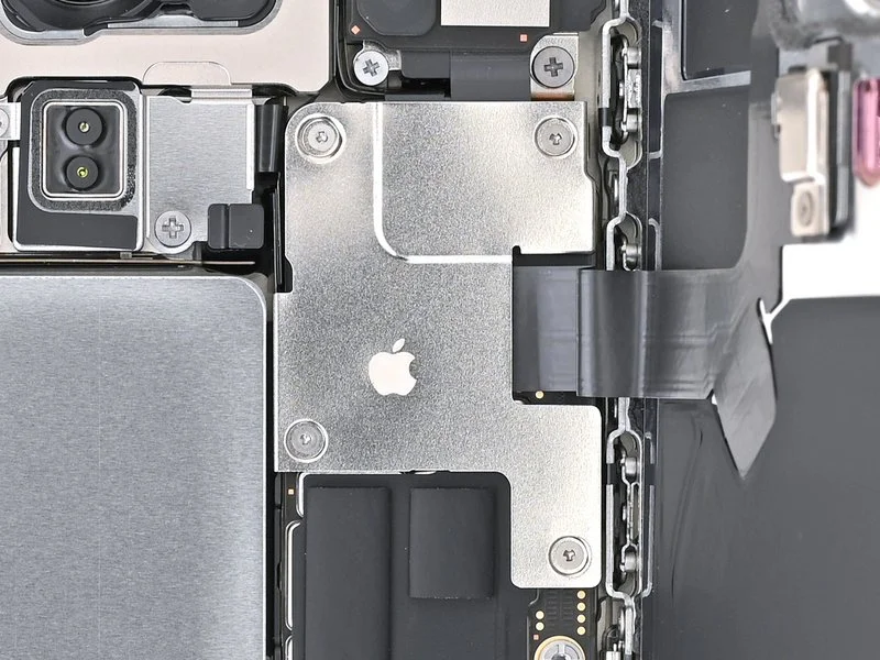
- Employ a tri-point Y000 screwdriver to detach the four screws that hold the upper connector cover in place.
- A quantity of two screws, each measuring 1.0 millimeters in length, are present.The assembly includes one screw with a length of 1.2 millimeters.A single screw, possessing a 1.6 millimeter length, is also incorporated.
- The upper connector cover is fastened by screws of varying sizes.Carefully unscrew the fasteners using the appropriate screwdriver.Ensure the tri-point Y000 screwdriver is properly seated on the screw heads to prevent damage.
- The screws are small and easily lost; keep track of them during removal.Note the screw lengths for correct reassembly; they are 1.0 mm, 1.2 mm, and 1.6 mm.Removal of the screws will allow access to the connector cover for further inspection or repair.
Step 20
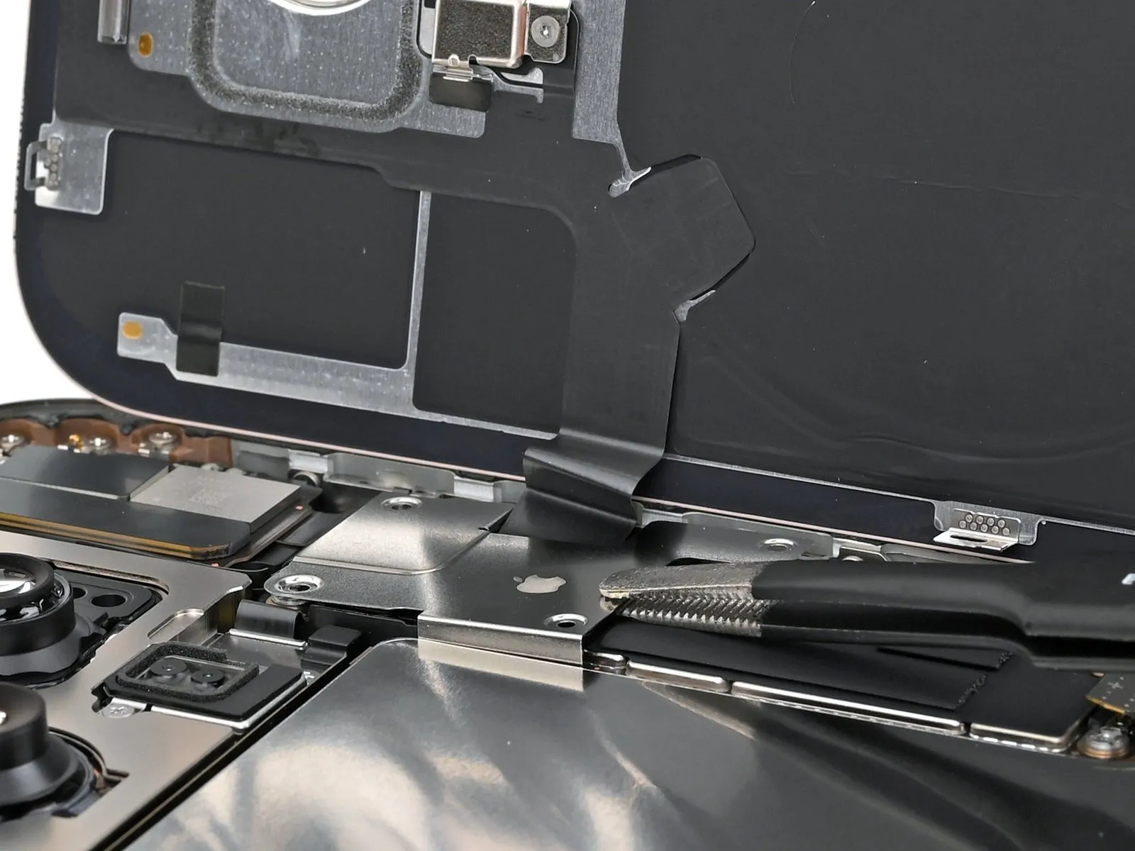

- Employing either tweezers or direct manual manipulation, carefully detach the upper connector cover.The upper connector cover can be dislodged by utilizing specialized tweezers or by grasping it with your fingertips.To facilitate removal, the upper connector cover should be lifted using tweezers or by hand.For the purpose of extracting the upper connector cover, tweezers are suitable, or it may be removed with a fingertip grasp.The upper connector cover necessitates removal, achievable through the application of tweezers or manual finger contact.
Step 21
Step 22 | Remove the back glass

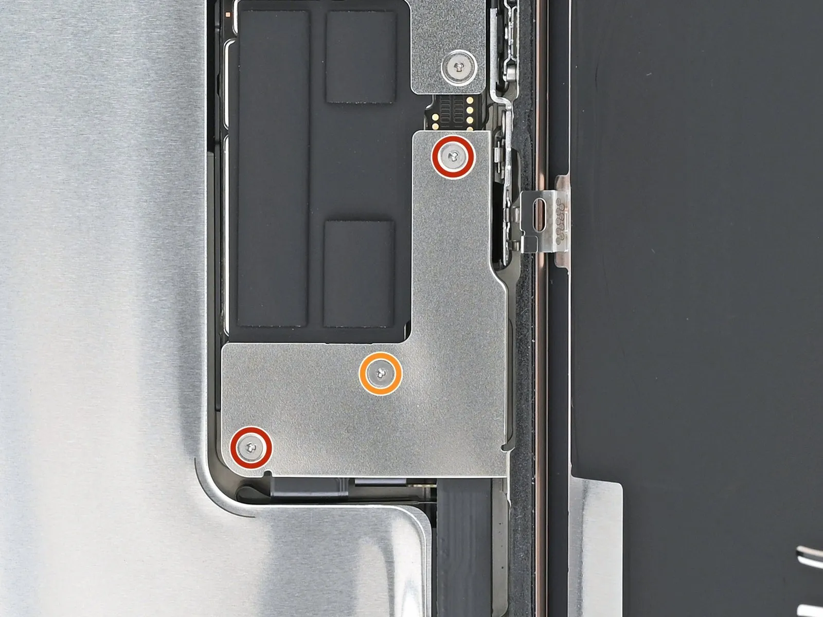
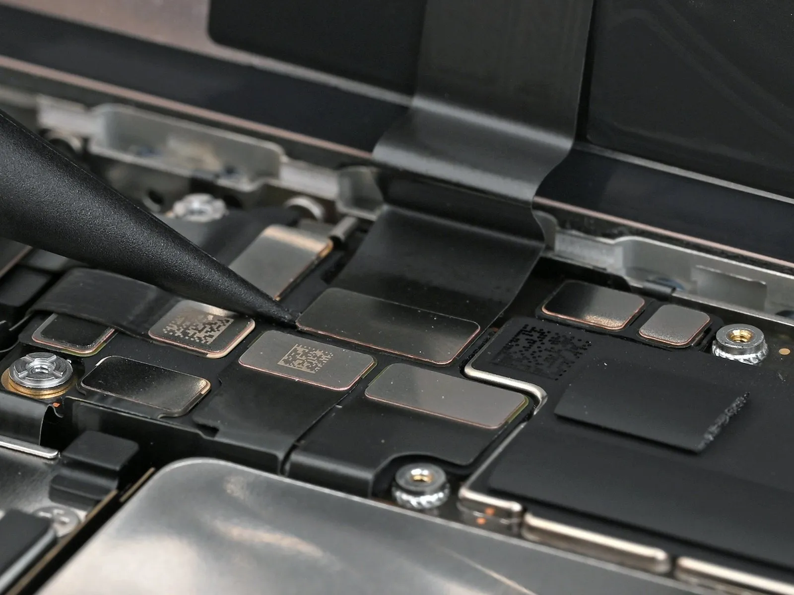
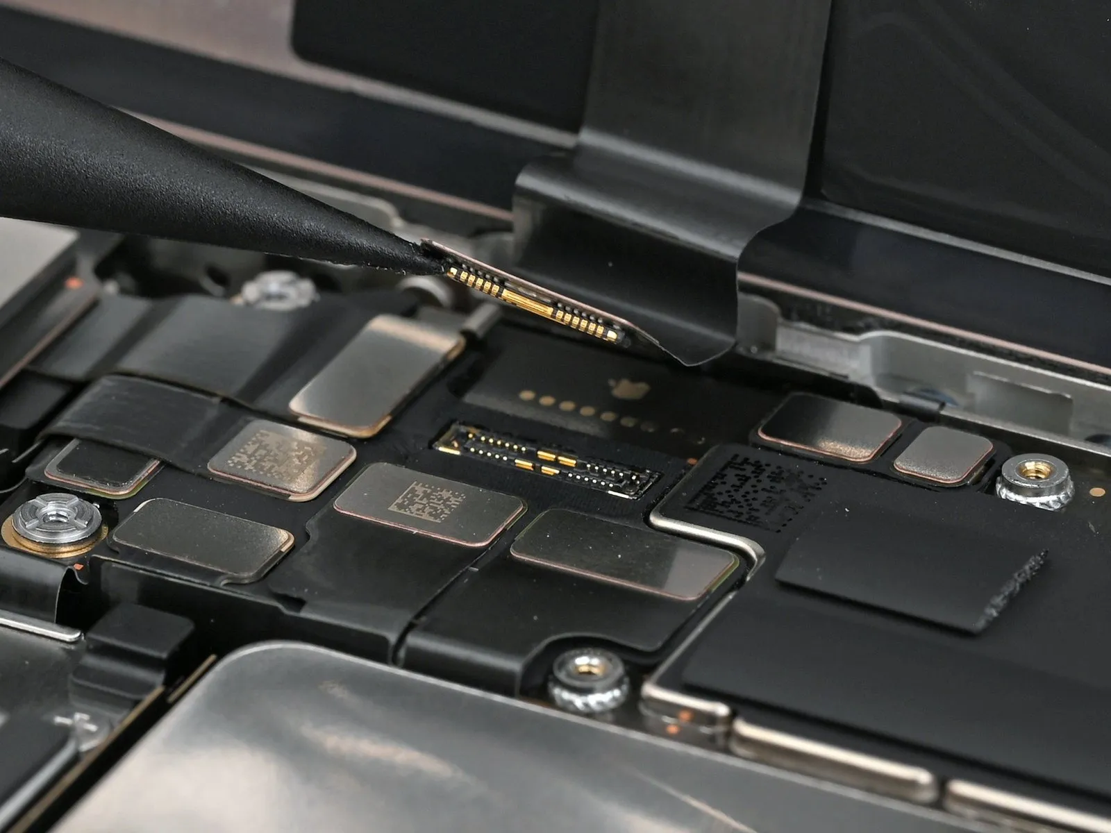
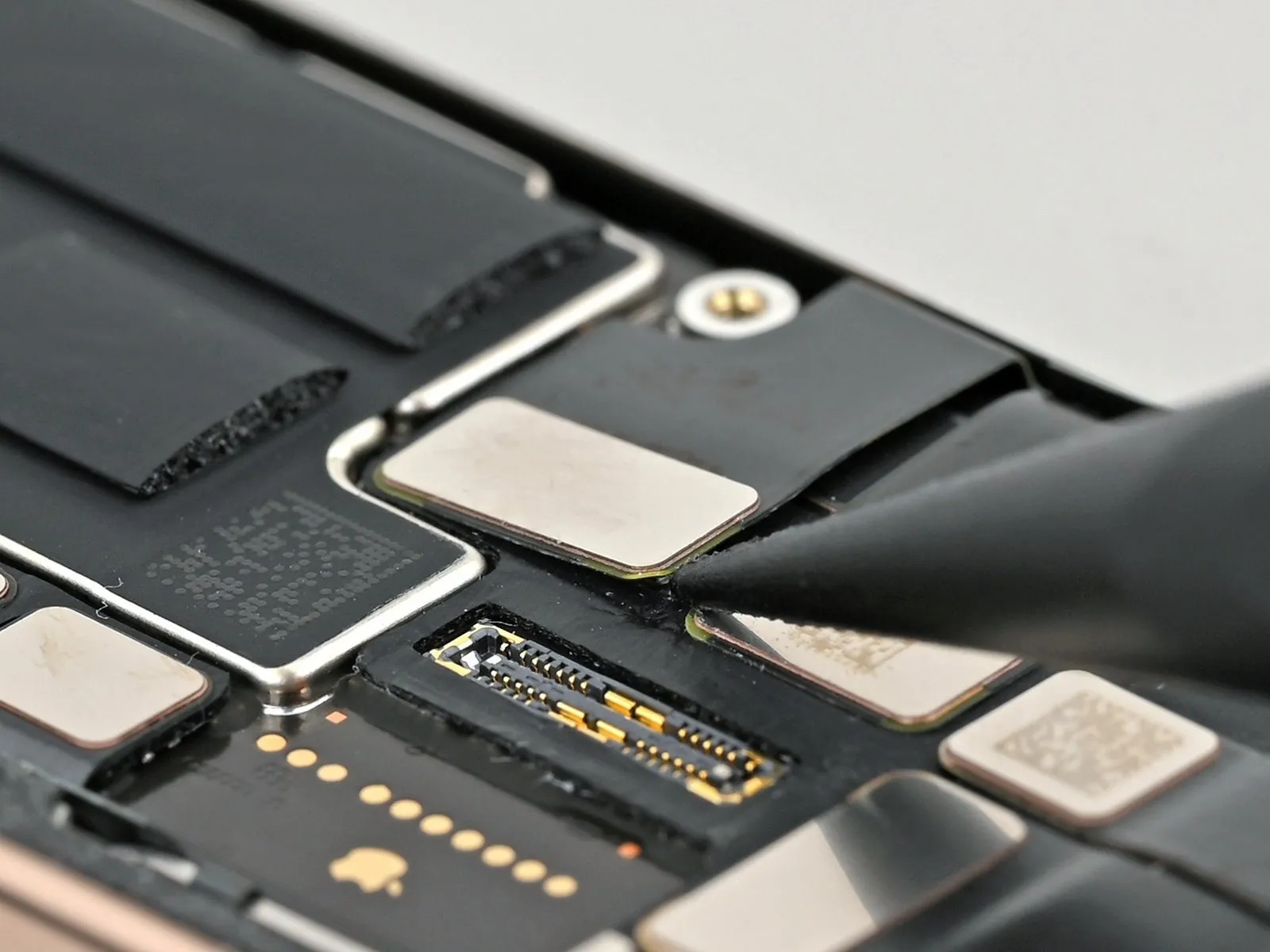
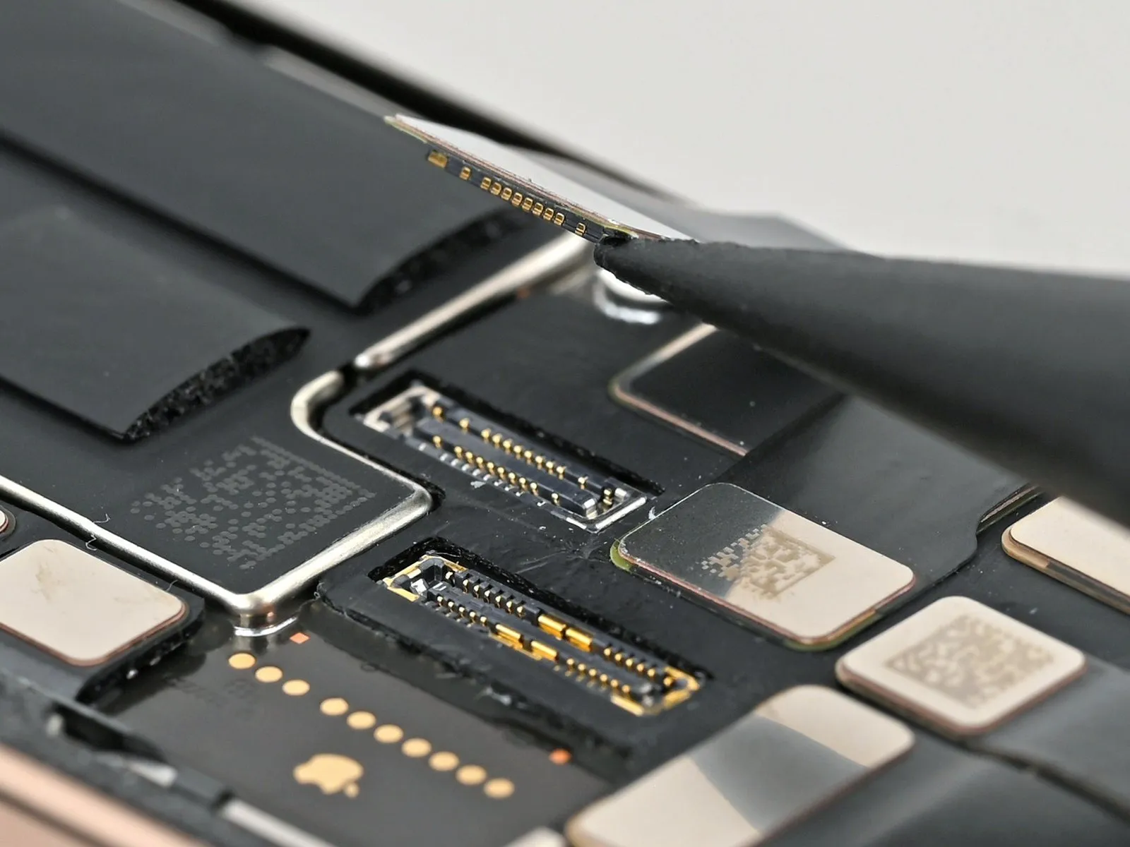
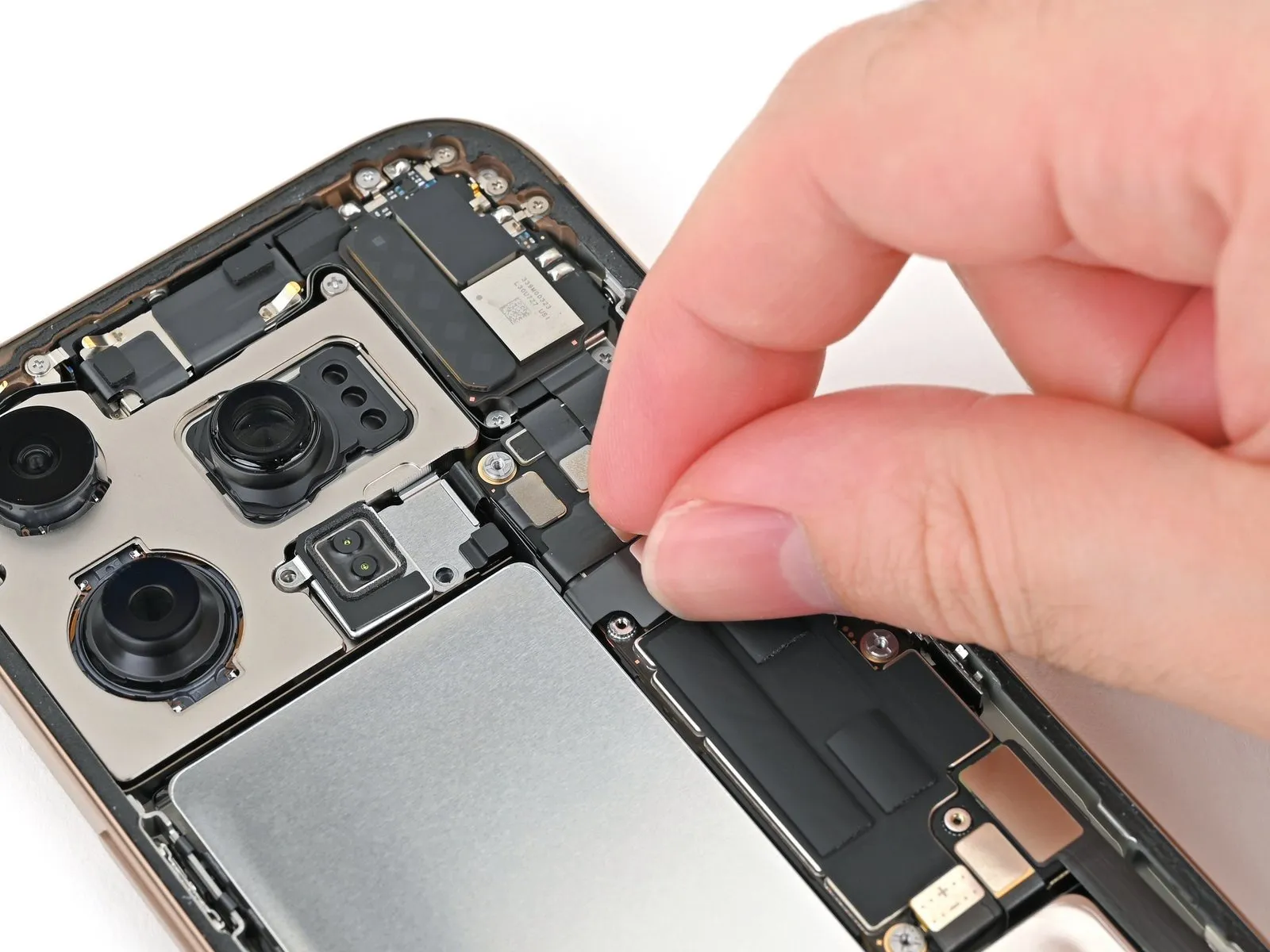
Step 23 | Disconnect the LiDAR sensor
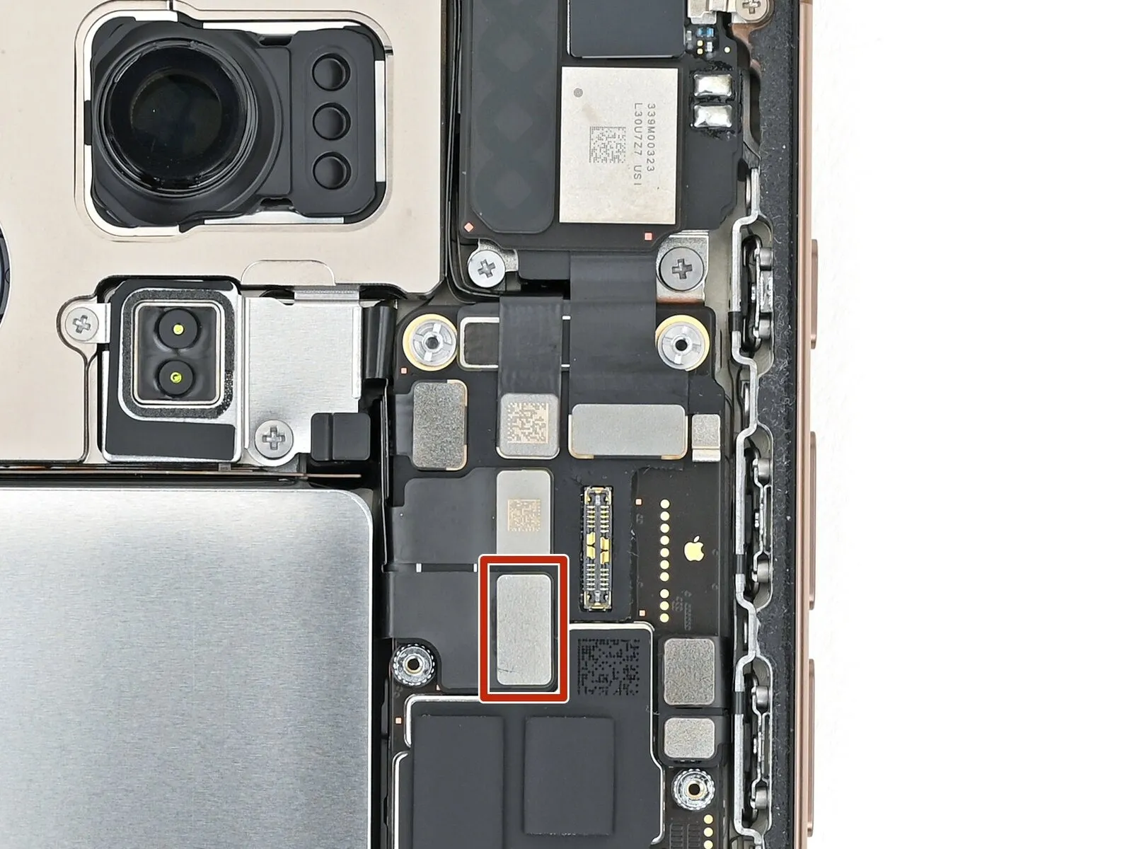
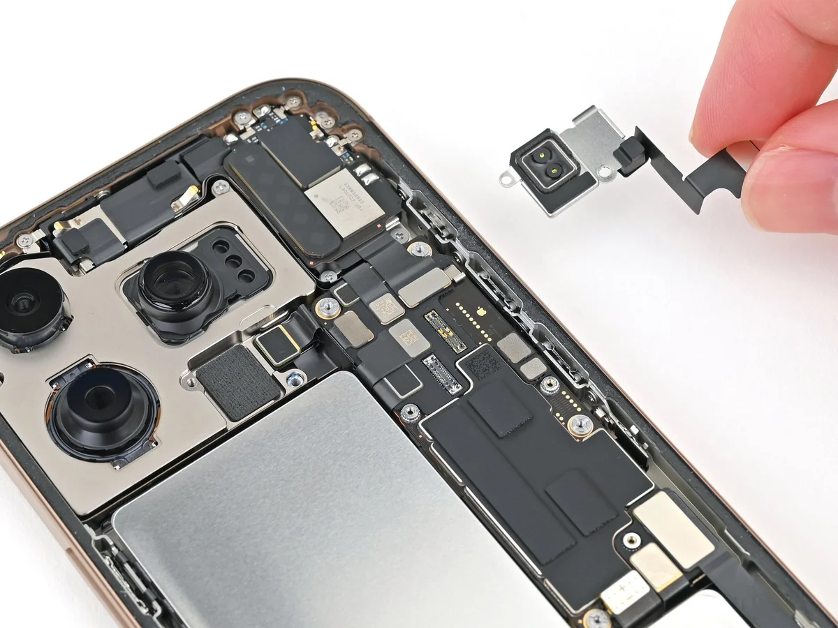
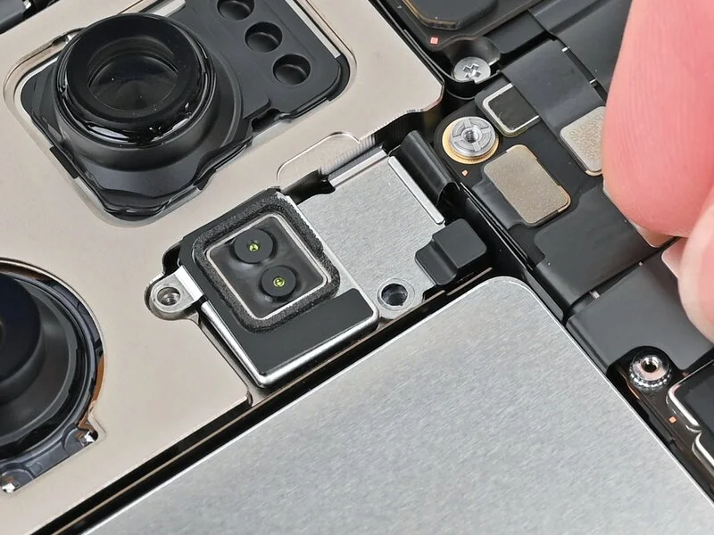
Step 24 | Remove the LiDAR Sensor
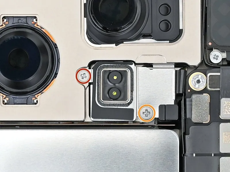
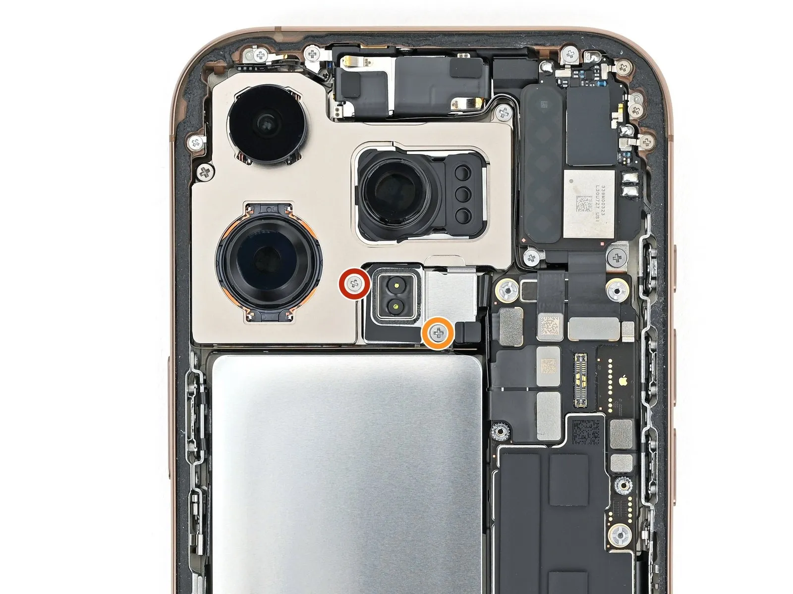
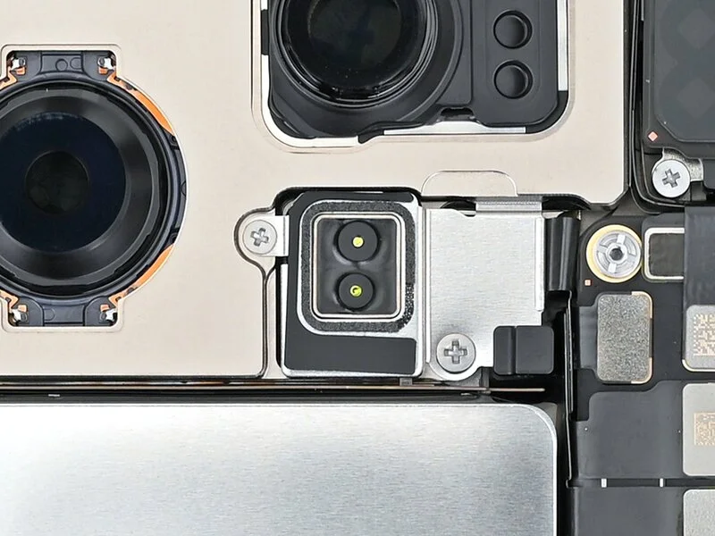
- Employ a Phillips screwdriver for the disassembly of the screws that hold the LiDAR sensor in place.A 1.7-millimeter screw is one of the fasteners used to secure the LiDAR sensor.The other fastener is a screw measuring 3.0 millimeters in length.
- The LiDAR sensor is affixed with two screws, requiring a Phillips screwdriver for their removal.
- To detach the LiDAR sensor, utilize a Phillips screwdriver and remove the two screws holding it in position; one is 1.7 mm long, and the other is 3.0 mm long.
Step 25
Step 26 | Disassembly complete

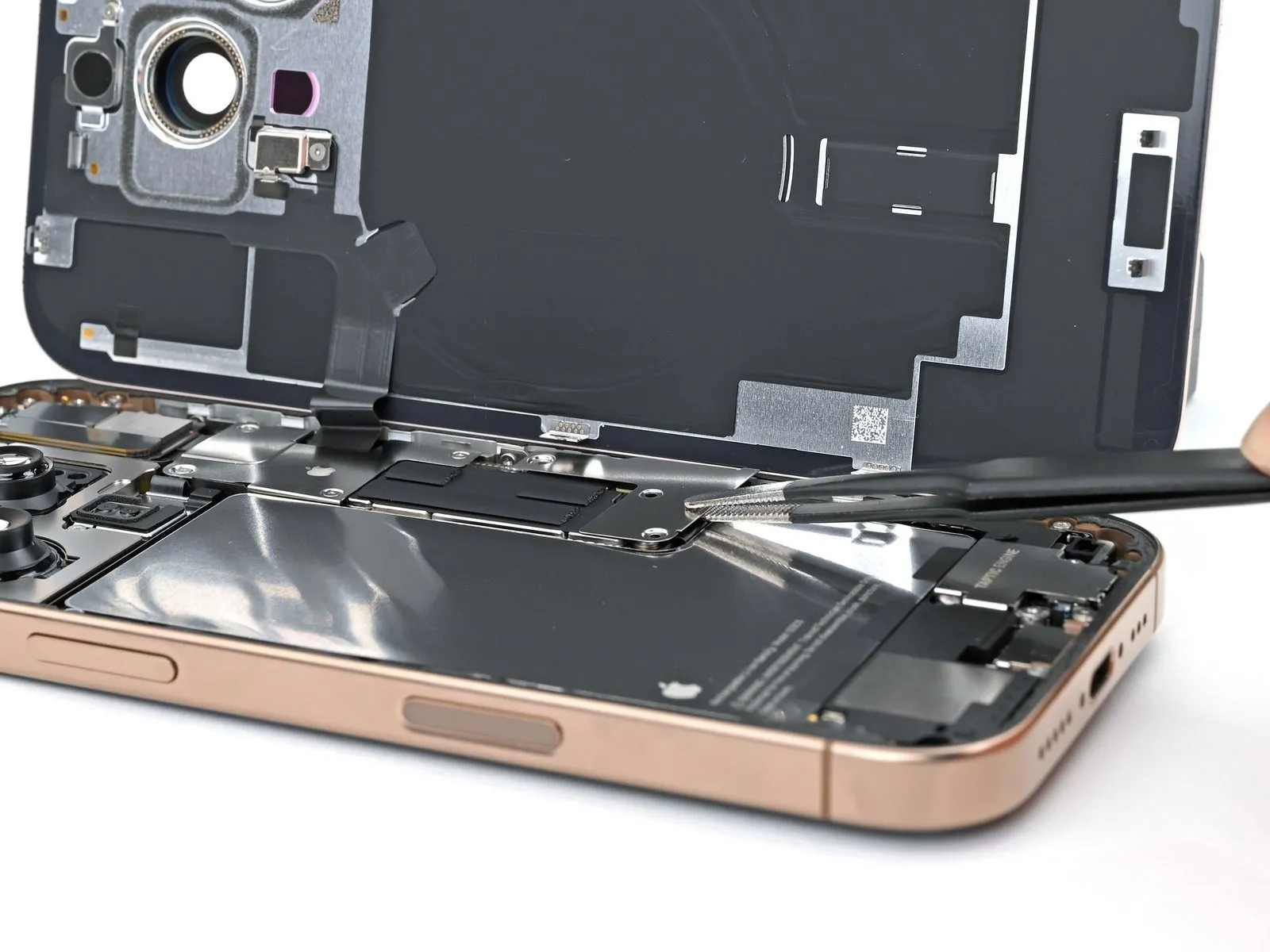
Step 27 | Install the LiDAR Sensor
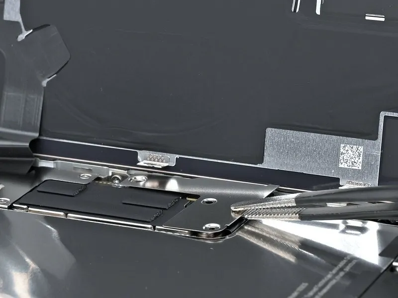
- Position the LiDAR sensor so that its screw apertures correspond with their intended locations.
- Confirm that the LiDAR sensor's connector is seated evenly positioned in the space located between the battery and the logic board.
Step 28
- A screw measuring 1.7 millimeters in length is required for this task.A second screw, with a length of 3.0 millimeters, is also necessary.
- Ensure proper alignment when installing the 1.7 mm and 3.0 mm screws to secure the LiDAR sensor.The installation of the LiDAR sensor necessitates the use of both a 1.7 mm and a 3.0 mm Phillips head screw.
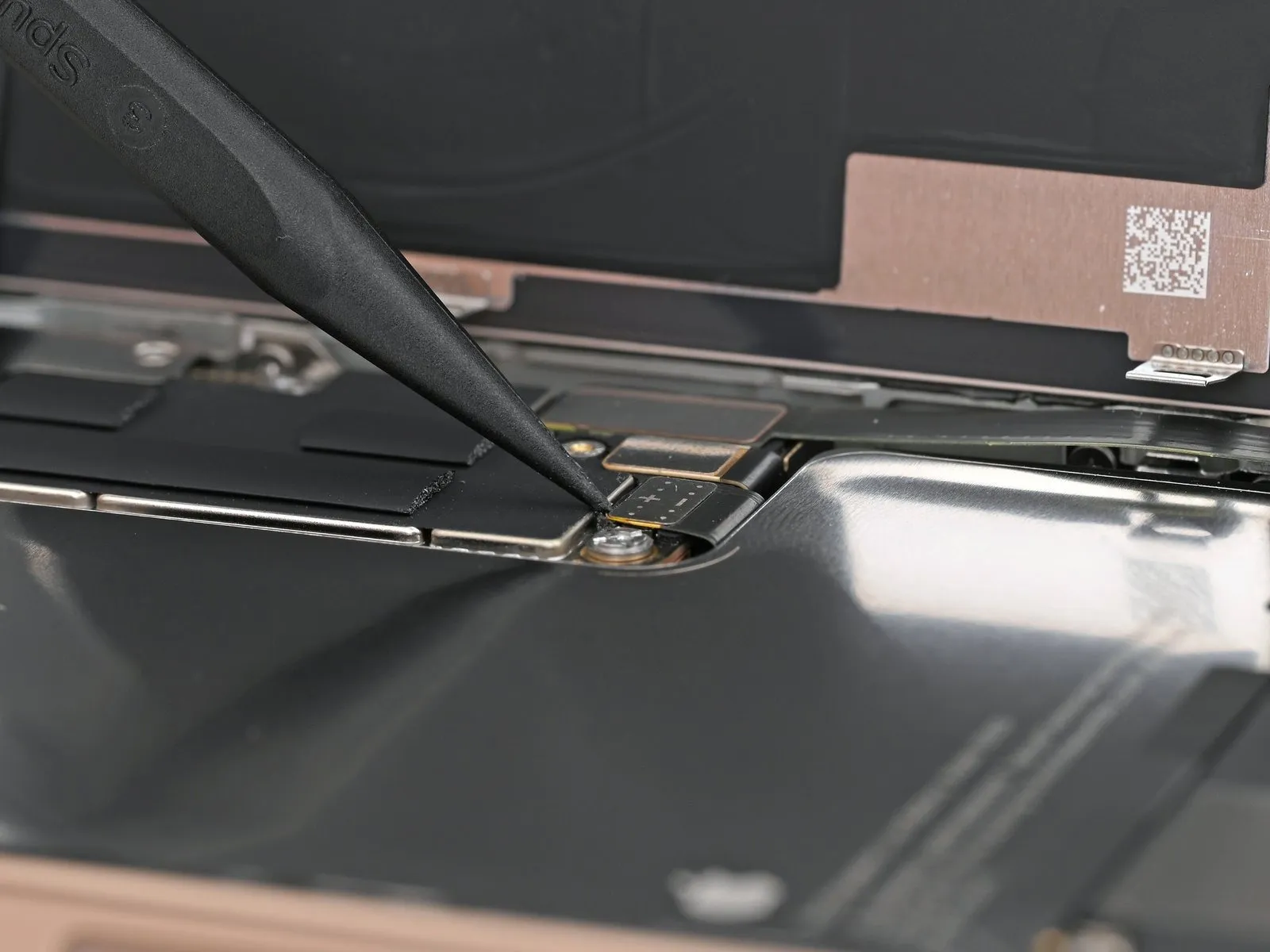
Step 29 | Connect the LiDAR sensor


Step 30 | Remove the leftover adhesive


- Exercise caution near the delicate grounding clips during frame cleaning to prevent damage.
- Employing blunt nose tweezers, or utilizing your fingertips, facilitates the removal of sizable adhesive sections from the frame's edges.A spudger is the appropriate tool for eliminating remaining adhesive residue adhered to the frame's surface.Persistent adhesive can be softened by applying warmth with a hair dryer or heat gun, then attempting removal.
- Should a grounding clip become displaced, carefully restore its original shape using your fingers or tweezers.
- The frame's perimeter should be cleared of substantial adhesive portions before proceeding with residue removal.
Step 31 | Clean the back glass


Step 32 | Clean the frame

- To prevent scratching, cover the spudger's tip with a clean, lint-free cloth or a coffee filter, then dispense a small quantity of isopropyl alcohol with a concentration exceeding 90 percent onto the covering.Employing a single direction, carefully remove adhesive remnants from the frame's edge by wiping.The cleaning process requires patience and deliberate action.
- A pristine frame surface facilitates a uniform application of replacement adhesive, which is crucial for a secure bond.
- Proper preparation of the frame’s surface is essential for optimal adhesion during the replacement process.
Step 33 | Apply the replacement adhesive

- To establish the correct positioning of the adhesive sheet relative to the frame, place it on the frame's surface.
- Employ frame elements like the camera aperture and the indentations situated on the upper and lower borders to aid in visualizing the adhesive's placement within the frame.
Step 34


- To reveal a portion of the adhesive, carefully lift the corner tab of the adhesive sheet's liner and remove it, exposing approximately one-third of the adhesive surface.
- Exercise caution, as the newly exposed adhesive possesses a high degree of tackiness; prevent unintended contact with other surfaces until it is prepared for application to the frame.
- Should your adhesive product incorporate multiple liners, remove only the uppermost liner to reveal the side intended for bonding to the frame.
Step 35


- Ensure the visible perimeter of the adhesive strip is precisely matched to the matching edge on the iPhone's chassis.
- Because the adhesive cannot be adjusted after initial contact, any misplacement necessitates complete removal and replacement with a fresh adhesive strip.
- After proper alignment has been achieved, apply even pressure to secure the adhesive strip to the iPhone's frame.
Step 36


- Carefully remove the adhesive backing, ensuring even contact with the surface by applying gentle pressure.
- Proper alignment of the adhesive is indicated by a seamless fit of the edges within the frame's boundaries.
- To correct minor adhesive misplacement, delicately reposition the longer sides toward the frame's structure.
- Should creases or wrinkles appear on the adhesive, discard it and apply a new strip for optimal results.
- In the absence of replacement adhesive strips, the iPhone can be reassembled and used, acknowledging a reduction in its water resistance until a proper seal is restored.
Step 37


- Employ a spudger to apply pressure to the adhesive sealant that secures the iPhone's frame.Exercise caution to avoid damaging the delicate grounding clips during this process; if displacement occurs, carefully reposition them using your fingers or tweezers.Excessive force should be avoided, as it can distort the adhesive's original shape.
- The adhesive perimeter requires complete engagement with the spudger for effective separation.
- Grounding clip misalignment can disrupt electrical connectivity and should be corrected with precision.
Step 38


- Employ a spudger tool, or manually use your fingers, to detach the pull tab affixed to the expansive front liner.The pull tab's typical location is situated within a corner of the liner.Utilize the pull tab to carefully separate the large front liner from the underlying adhesive.
- A remaining liner may persist along the edges, safeguarding the adhesive during reassembly; refrain from removing these smaller release liners at this stage.
- These peripheral liners serve to prevent premature adhesion during the reassembly process.
Step 39 | Connect the back glass

To facilitate access, carefully wedge the rear glass panel upward, maintaining pressure along its right-hand border.
Step 40

Employing either a fingertip or the planar edge of a spudger tool, ensure the back glass connector's secure attachment to the logic board through gentle pressure.To establish a reliable electrical connection, apply force with a finger or the broad, flat surface of a spudger tool to the back glass connector, positioning it against the logic board.A firm, even pressure, achievable with a finger or the flat end of a spudger, is necessary to properly seat the back glass connector onto the logic board’s surface.
Step 41 | Connect the battery

- Initiate the iPhone's power sequence to verify proper operation; subsequently, deactivate it to proceed with the remaining assembly steps.
- Should the iPhone fail to power on initially, establish a connection to a power source and attempt the power-on sequence again.
- In the event that a logic board replacement has been performed and the display remains unresponsive, consult the dedicated screen repair guide for manual connection of the display connector.
- Ensure the battery press connector is firmly seated on the logic board by applying pressure with a finger or spudger.
Step 42 | Install the connector covers

Step 43

- The cover is secured with two screws, each measuring 1.3 millimeters in length.
- Additionally, two screws with a length of 1.0 millimeters are utilized.
Step 44

Step 45

- A single screw within the assembly is 1.0 millimeters long.Proper tool selection is essential for preventing damage to the screw heads.
- Carefully align the driver with the screw recesses during installation.Ensure the screws are fully seated to maintain the cover's secure attachment.
Step 46 | Remove the final adhesive liners


- Employing either your fingertips or a specialized spudger tool, carefully separate the surrounding adhesive protective layers to reveal the underlying adhesive.
- During liner removal, prevent any contact between surfaces and the newly exposed adhesive to maintain its bonding properties.
- Thoroughly inspect both the device frame and rear glass assembly, eliminating any residual liners to guarantee a completely clean adhesive surface.
Step 47 | Install the back glass


- Position the rear glass component onto the device frame, initiating the placement with the uppermost boundary.
- Should you encounter opposition during installation, a surrounding retaining clip might be deformed and experiencing compression from the frame; carefully examine the area of resistance and delicately correct any deviations from their original shape.
- Apply even pressure across the iPhone's borders to ensure the rear glass makes complete contact with the frame.
Step 48 | Apply heat to the perimeter

- Apply warmth to the outer edge of the rear glass utilizing a hair dryer, heat gun, or iOpener until the surface reaches a temperature just beyond comfortable touch.
- This thermal application reduces the adhesive's viscosity, facilitating a superior re-bonding process.
Step 49 | Apply pressure to the perimeter


Employ your fingertips to apply consistent, secure pressure encompassing the entire circumference of the iPhone's casing.
Step 50


- Position the iPhone with its screen facing downwards onto a pristine, level workspace.
- Apply adhesive tape along the outer edge of the rear glass to safeguard its cosmetic appearance.
- Arrange a circular stack of coins bordering the rear glass, constructing a barrier matching the height of the rear camera lenses.
- As an alternative method, secure the device with vise clamps around its outer edges to properly establish the fresh adhesive seal.
Step 51


- To apply even pressure, position four to five substantial volumes directly atop the iPhone’s surface.
Because the weight could potentially create a minor mark on the book's exterior, avoid utilizing precious or irreplaceable materials.
Maintain the applied pressure by keeping the books in their position for approximately half an hour.
This sustained force facilitates the bonding process of the adhesive material.
Step 52 | Install the pentalobe screws
- Employ a P2 pentalobe screwdriver for the installation process.Secure the two screws, each measuring 7.4 millimeters in length, using the specialized screwdriver.These screws are positioned bilaterally, flanking the USB-C port.Properly engaging the P2 pentalobe driver is crucial for accurate screw placement.Ensure the screws are tightened adequately to maintain the integrity of the USB-C port assembly.