iPhone 16 Pro Taptic Engine Replacement
Use these instructions to substitute a new component.The device incorporates a Taptic Engine.Within the iPhone 16 Pro.
A replacement of theThe device incorporates a Taptic Engine.A lack of or diminished haptic feedback from your iPhone may be present.
- To finish the repair, ensure you have new adhesive specifically designed for the back glass.
Step 1 | Prepare the phone for disassembly


- Let the battery discharge until its voltage drops below.One-quarter.Because fully charged lithium-ion batteries present a possible safety risk.
- Disconnect all wires and cords connected to the device.
- Simultaneously press and maintain the power button and one of the volume buttons, then slide to initiate the power-off sequence.
Step 2 | Tape over any cracks
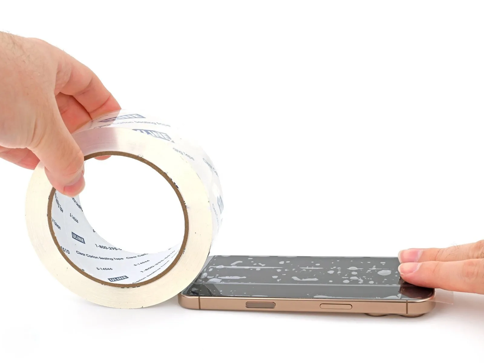
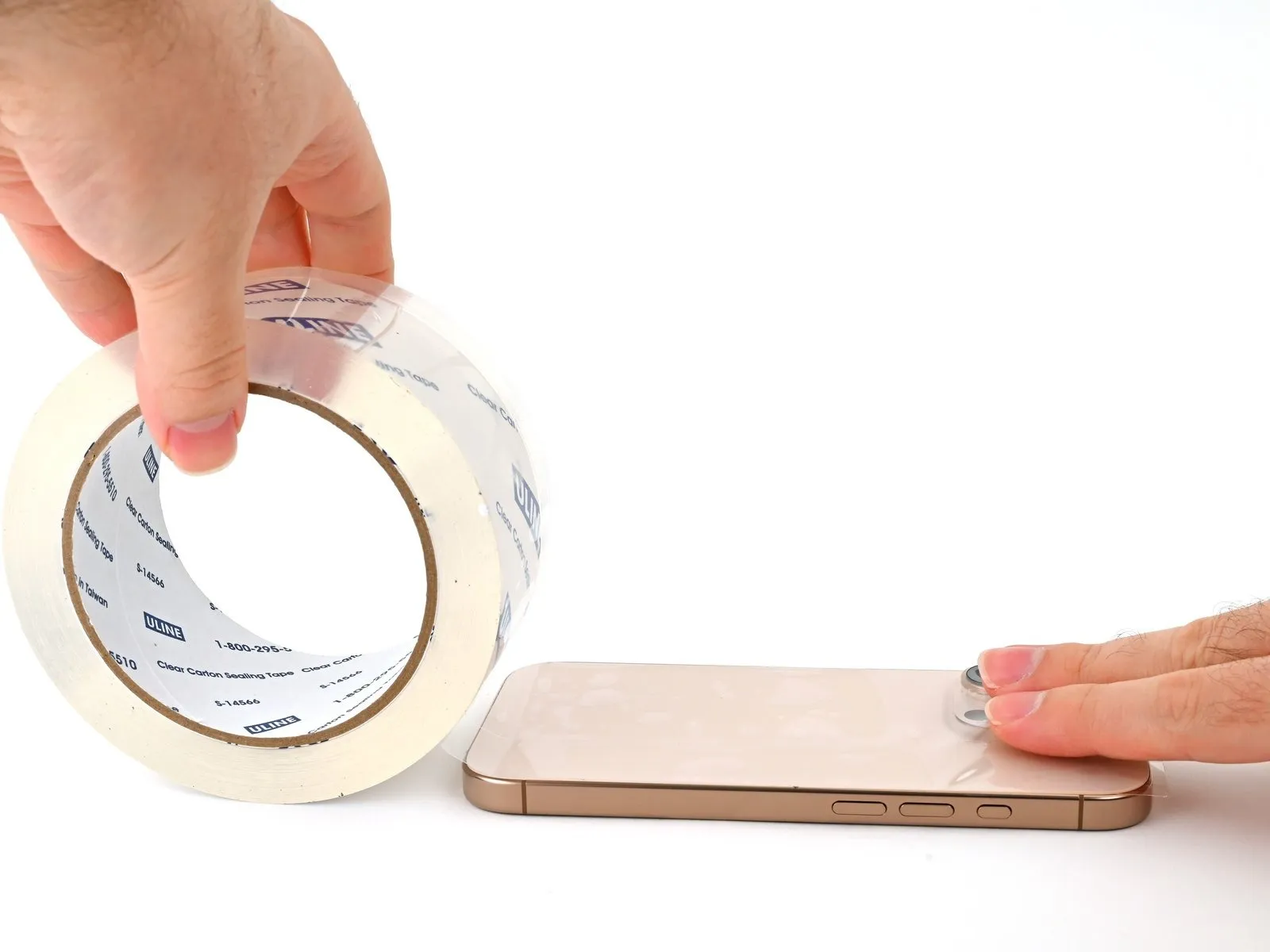
- To prevent injury and simplify the repair process when the display or rear glass exhibits severe cracking, apply strips of packing tape that slightly overlap each other across the damaged areas.
- Ensure a flat surface, approximately the size needed to accommodate a suction cup, exists close to the lower perimeter.
Step 3 | Mark your opening picks


- To avoid potential damage to your device, ensure the opening pick does not extend beyond a safe depth; to assist with this, mark the pick according to the following procedure.
- Determine the dimension using a measuring tool.Three millimeters.Using a permanent marker, clearly indicate the opening point on the pick.
- To allow for varied grip preferences, the remaining corners of the pick can be individually marked with the same measurement options.
- To provide extra grip for accessing the SIM card tray, securely affix a coin to the end of a SIM card removal tool.Three millimeters.Beginning at the very end, proceed from that point.
Step 4 | Remove the pentalobe screws
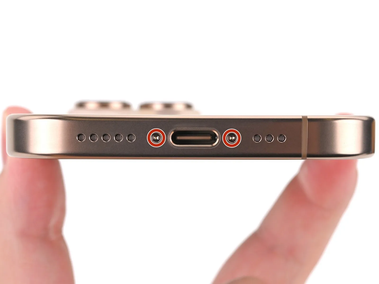

Employ a P2 pentalobe screwdriver to detach the two.The specified dimension is seven point four millimeters.Secure the USB-C port with the two long screws, one on each side.
Step 5 | Heat the bottom edge
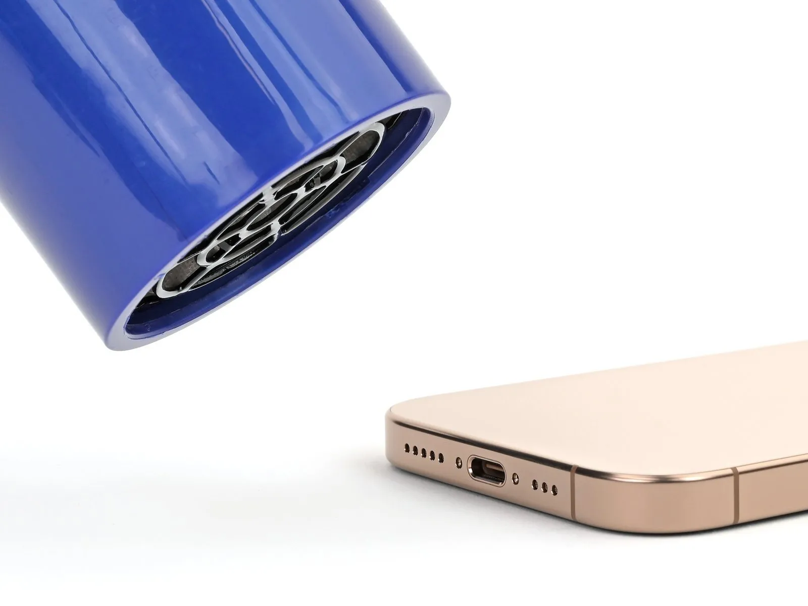
- Using a heat source, introduce it to the surface.Use the iOpener.Apply consistent pressure to the lower border of the rear glass panel for a duration of 120 seconds.
- Applying heat to the lower edge of the rear glass with a hair dryer or heat gun, until it reaches a temperature safe to touch, is another option.
- To prevent heat-related battery damage, ensure the device's temperature remains below the specified limit.
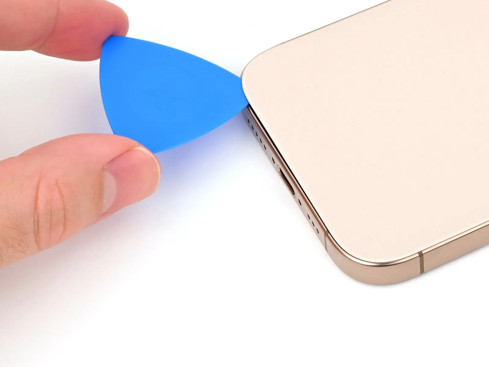
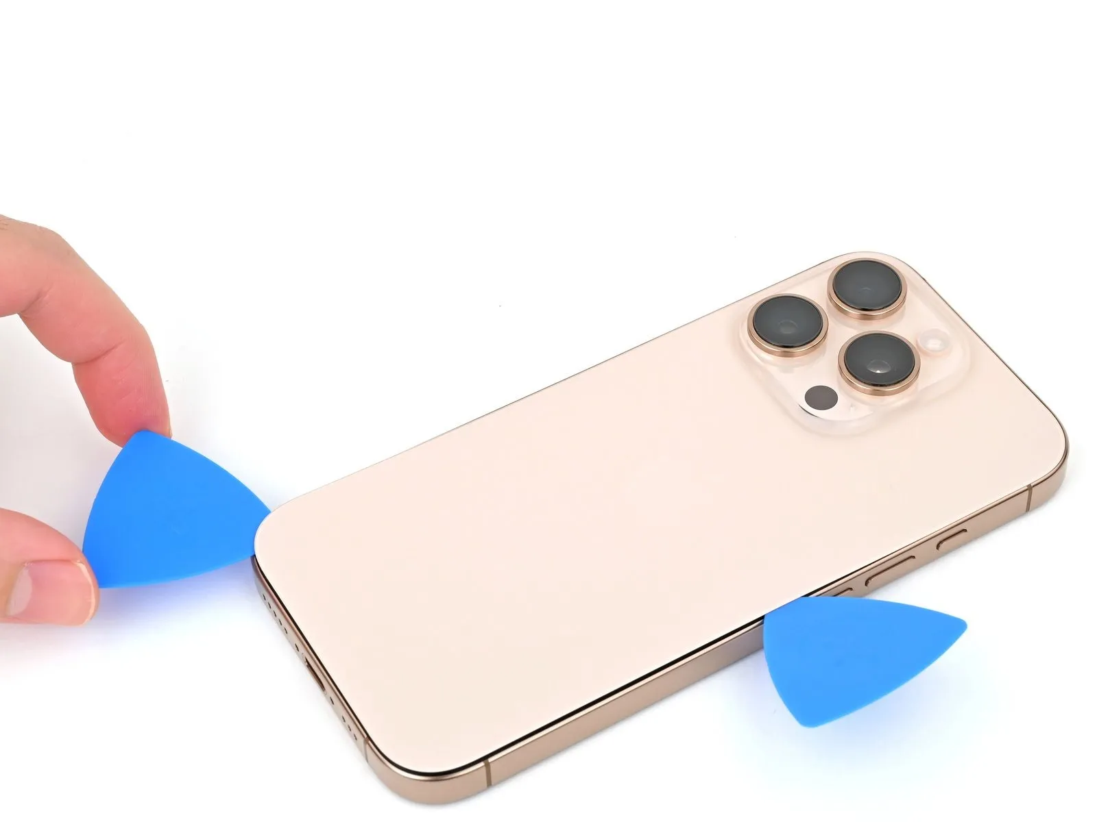
Step 6 | Insert an opening pick
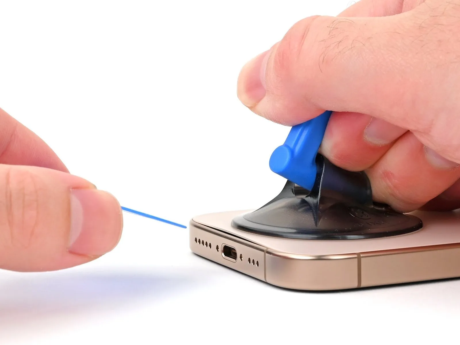
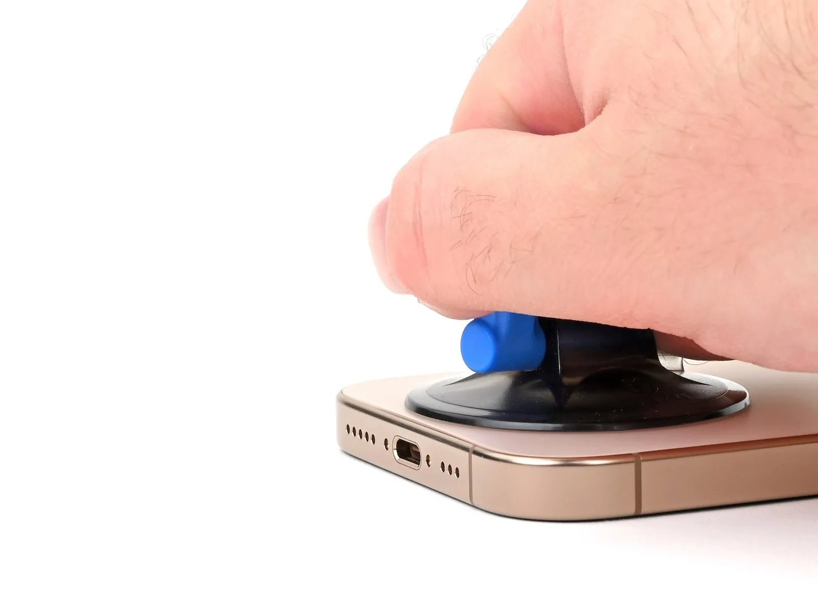

- Using a suction handle, secure it to the lower edge of the rear glass, positioning it directly over the USB-C port.
- Apply firm, consistent upward pressure to the handle to separate the rear glass from the frame.
- Carefully slide the pointed end of a prying tool into the separation.
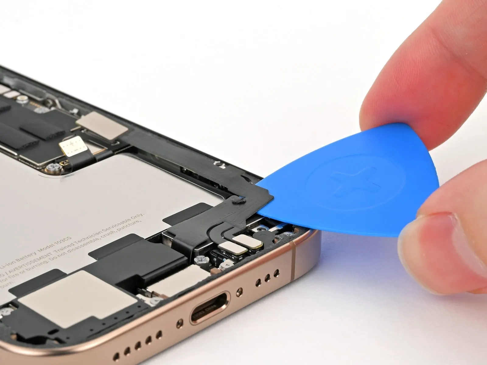
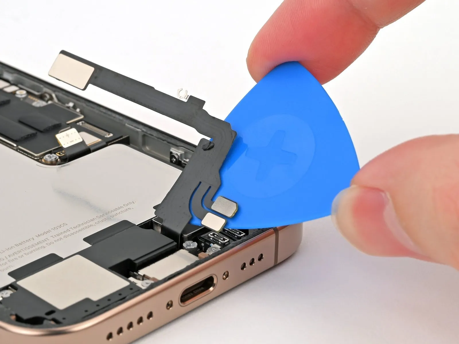
Step 7 | Back glass information
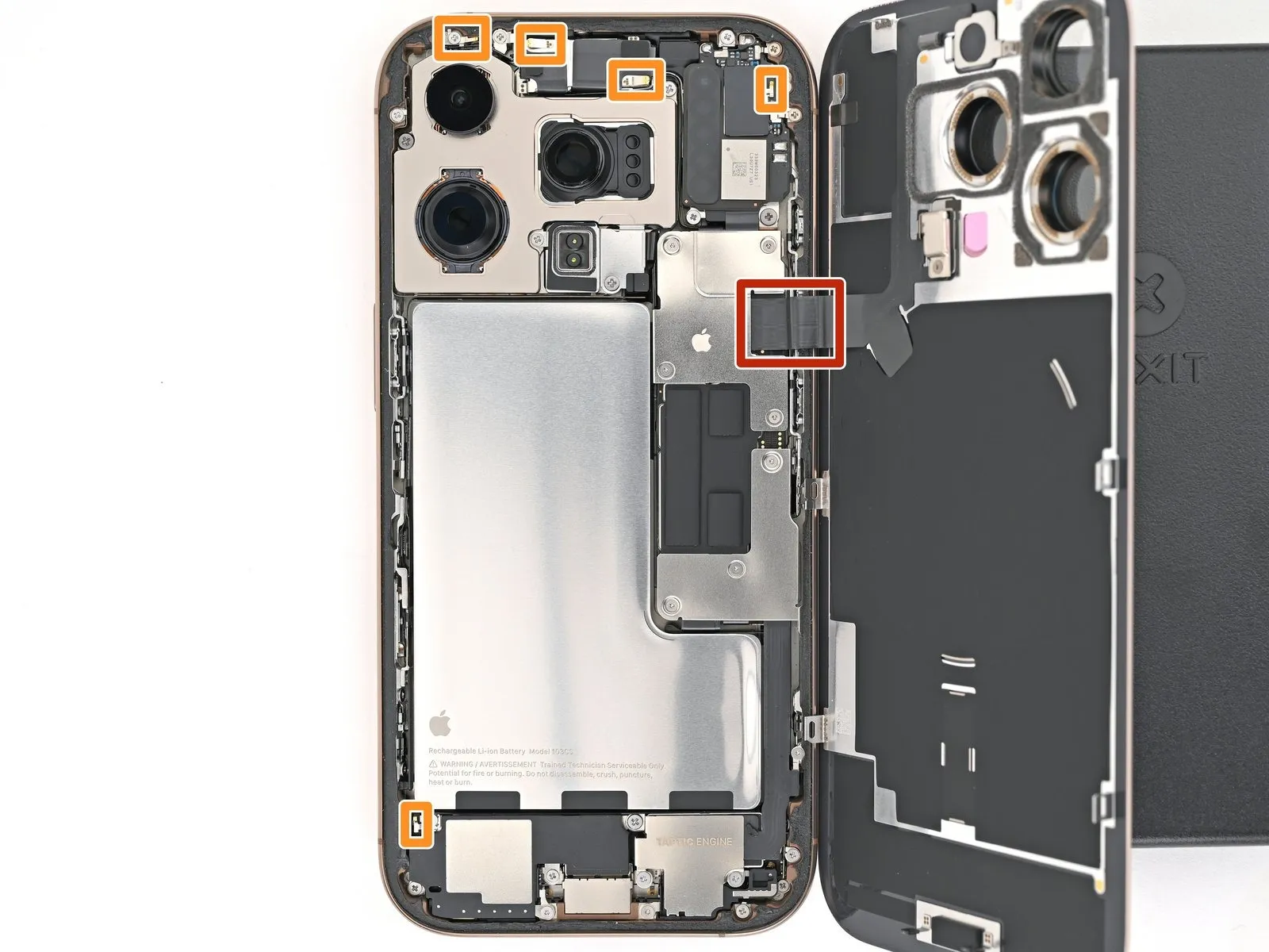
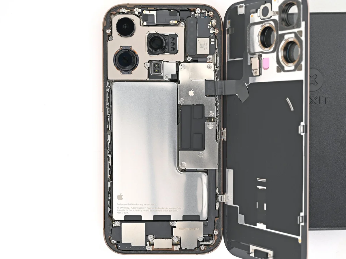
- Exercise caution while separating the back glass adhesive during subsequent procedures, specifically avoiding damage to these zones.
- To prevent damage to the fragile cable situated adjacent to the volume up button, refrain from using a prying tool in that area when separating the rear glass from the device.
- To prevent damage, exercise caution and limit the depth of your tool insertion during each step, as delicate spring contacts are situated along the phone's edges.
- Using a spudger or opening pick, carefully reshape any damaged spring contacts to ensure proper alignment with the gold contact pads located on the rear glass.
Step 8 | Separate the bottom edge adhesive

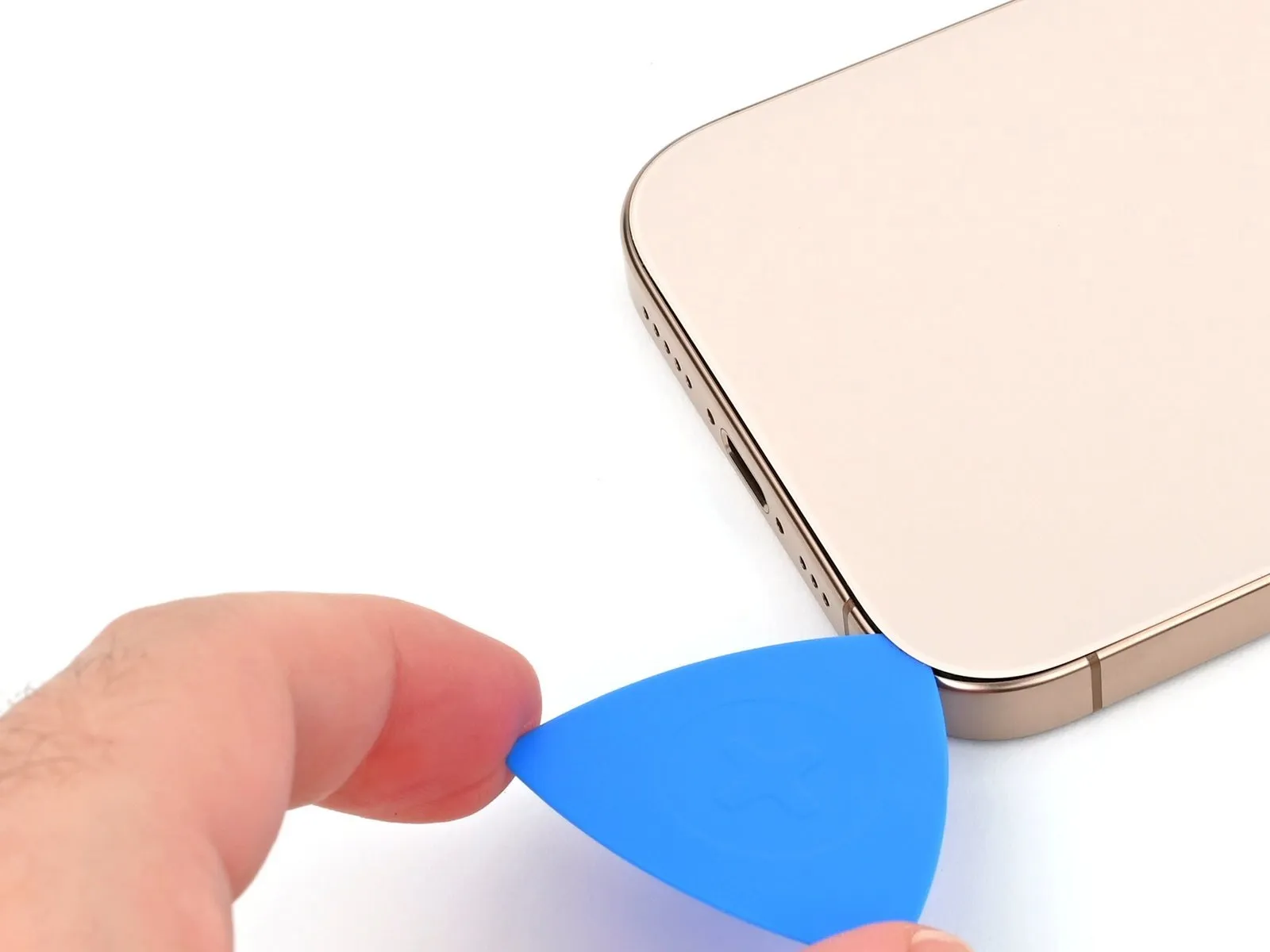
- To prevent spring contact damage, limit the insertion depth of your pick to a maximum of 5 mm when working on the bottom edge.
- Using a pick, gently work along the lower edge, moving it back and forth to loosen the adhesive bond.
- To stop the adhesive from bonding prematurely, maintain a pick in the lower right-hand corner.
Step 9 | Heat the right edge

- Apply heat to the right side of the rear glass panel until its surface temperature is high enough to be felt as hot when touched.
Step 10 | Separate the bottom right corner adhesive
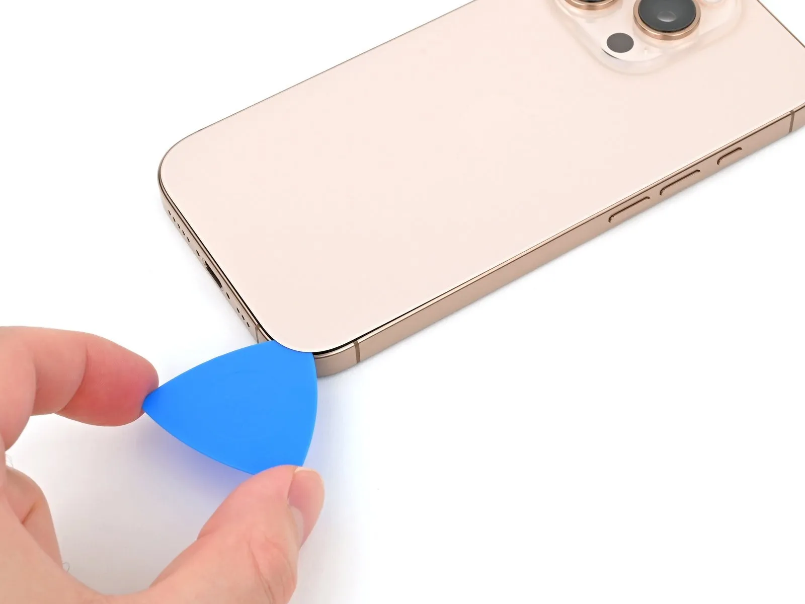

- Carefully insert a pick into the gap at the bottom right corner, progressing upwards along the right edge to a point midway up, stopping when you encounter the retaining clip that secures the rear glass.
- To prevent damage to the wireless charging/flash cable, exercise caution and avoid cutting in the vicinity of the volume buttons.
- Maintain the pick's position during the adhesive curing process to avoid unintended bonding.
Step 11 | Heat the left edge

- Apply heat to the left side of the rear glass panel until its surface temperature is high enough to be felt as hot when touched.
Step 12 | Separate the left edge adhesive

- Position another opening pick along the lower margin.
- Using the second pick, carefully work it along the left side of the screen, starting at the bottom left corner, to loosen the adhesive and disengage the metal clips.
- As the clips slide past, you will notice and sense them disengaging.
- Maintain the pick's position in the upper left corner to obstruct adhesive re-bonding.
Step 13 | Heat the top edge

Apply heat to the upper perimeter of the rear glass, encompassing the volume button region, until the surface reaches a temperature that is comfortably warm to the hand.
Step 14 | Separate the top edge adhesive


- Avoid pushing the tool past the specified depth.Three millimeters.To prevent damage to the spring contacts, maneuver the component along the upper edge.
- Carefully insert a separation tool along the upper edge, progressing around the top right corner until it reaches the volume up button, to break the adhesive seal; listen and feel for the distinct clicks indicating the release of the two upper retaining clips.
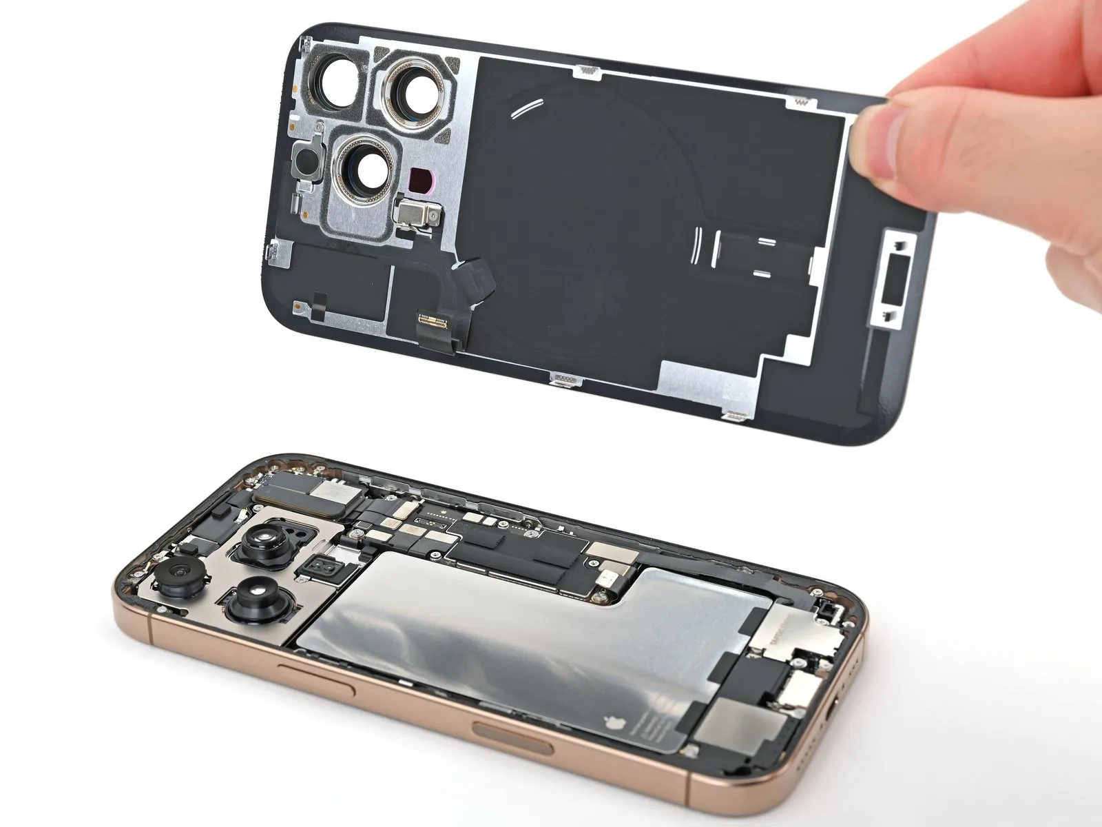
Step 15 | Swing open the back glass
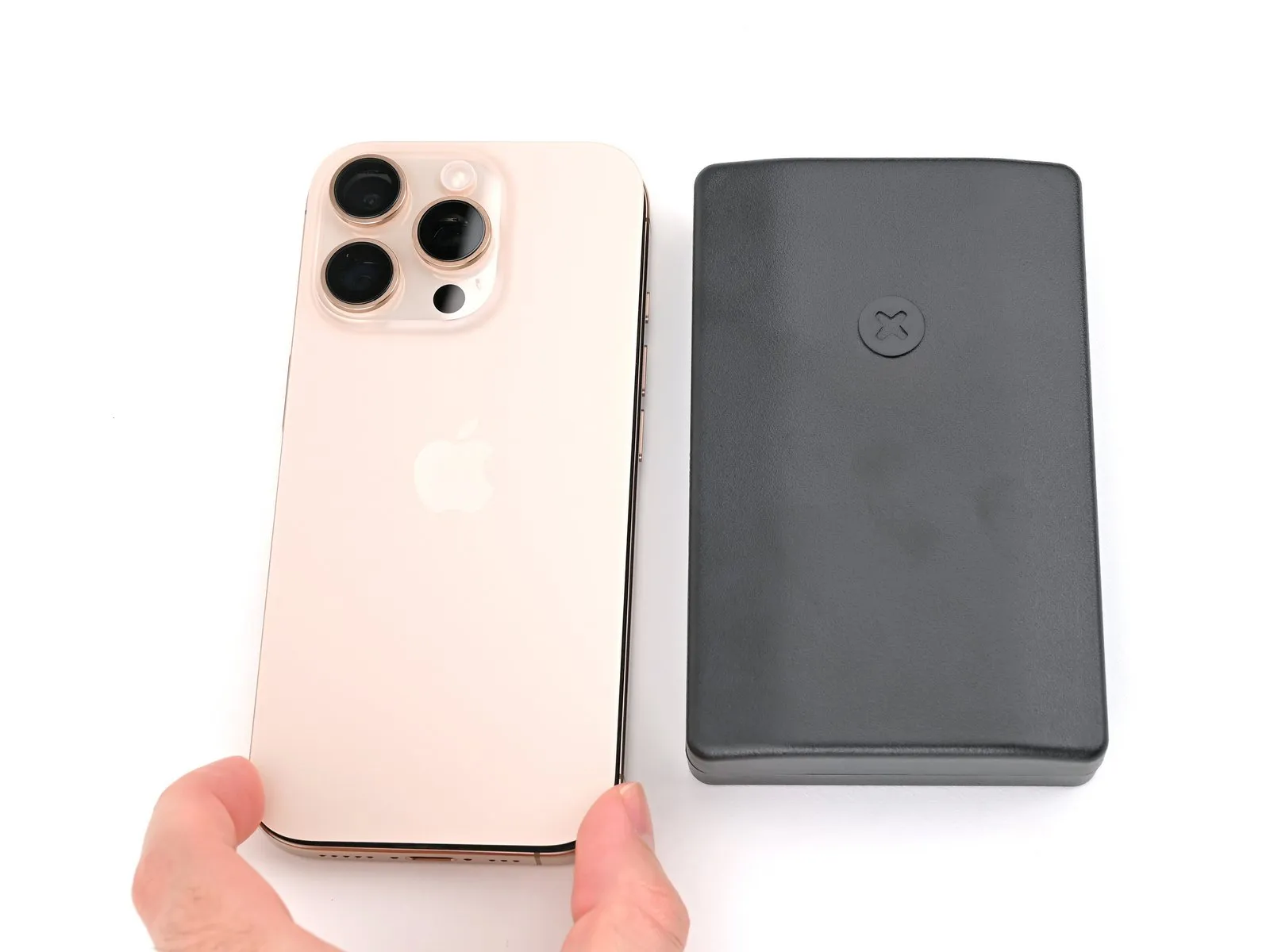
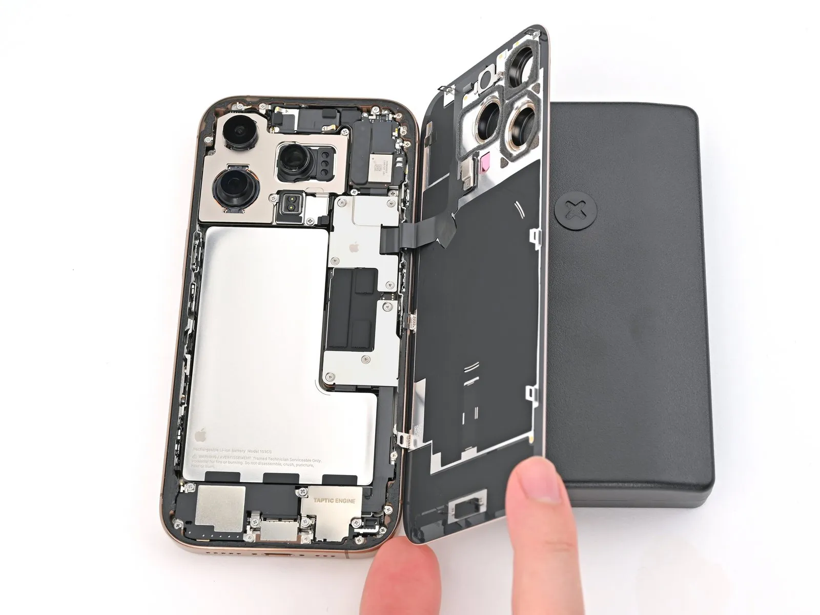
Avoid complete separation of the rear glass at this stage, as it remains connected via a fragile ribbon cable; proceed with the subsequent instructions to ensure safe detachment.
- Should you encounter resistance when attempting to open the rear glass, avoid applying excessive force; instead, carefully retrace the edges with your pick to identify and release any remaining adhesive or clipped fasteners.
- To ensure the retaining clips separate completely, a small upward movement of the rear glass might be necessary prior to pivoting it outwards.
- Carefully pivot the rear glass assembly away from the volume controls.
- To prevent damage to the cable, use a rigid, non-contaminating item—such as a small box—to provide backing for the rear glass during the repair.
- Take out the opening picks.
- To shield the rear camera lenses from potential scratches during internal repairs, apply polyimide tape; exercise caution and avoid applying pressure to the lenses themselves to prevent harm to their sensitive stabilization components.
Step 16 | Disconnect the battery
- Employ a three-pronged screwdriver.Use a Y000-type screwdriver.Loosen and extract the three screws that hold the lower connector cover in place.
- Two.One point two millimeters.Utilize screws with a length designated as "long."
- Begin the process by executing the singular action.One millimeter.Utilize a screw with a substantial length.
Step 17

- Employ the specified tool to perform the action.Employ fine-tipped pliers or similar precision instruments.orUse your hands.Gently lift and detach the lower connector cover.
Step 18
- Carefully employ the tip of a screwdriver to apply pressure.Use a plastic pry tool, often referred to as a spudger, to gently separate components.Use a prying tool to release and detach the battery press connector.
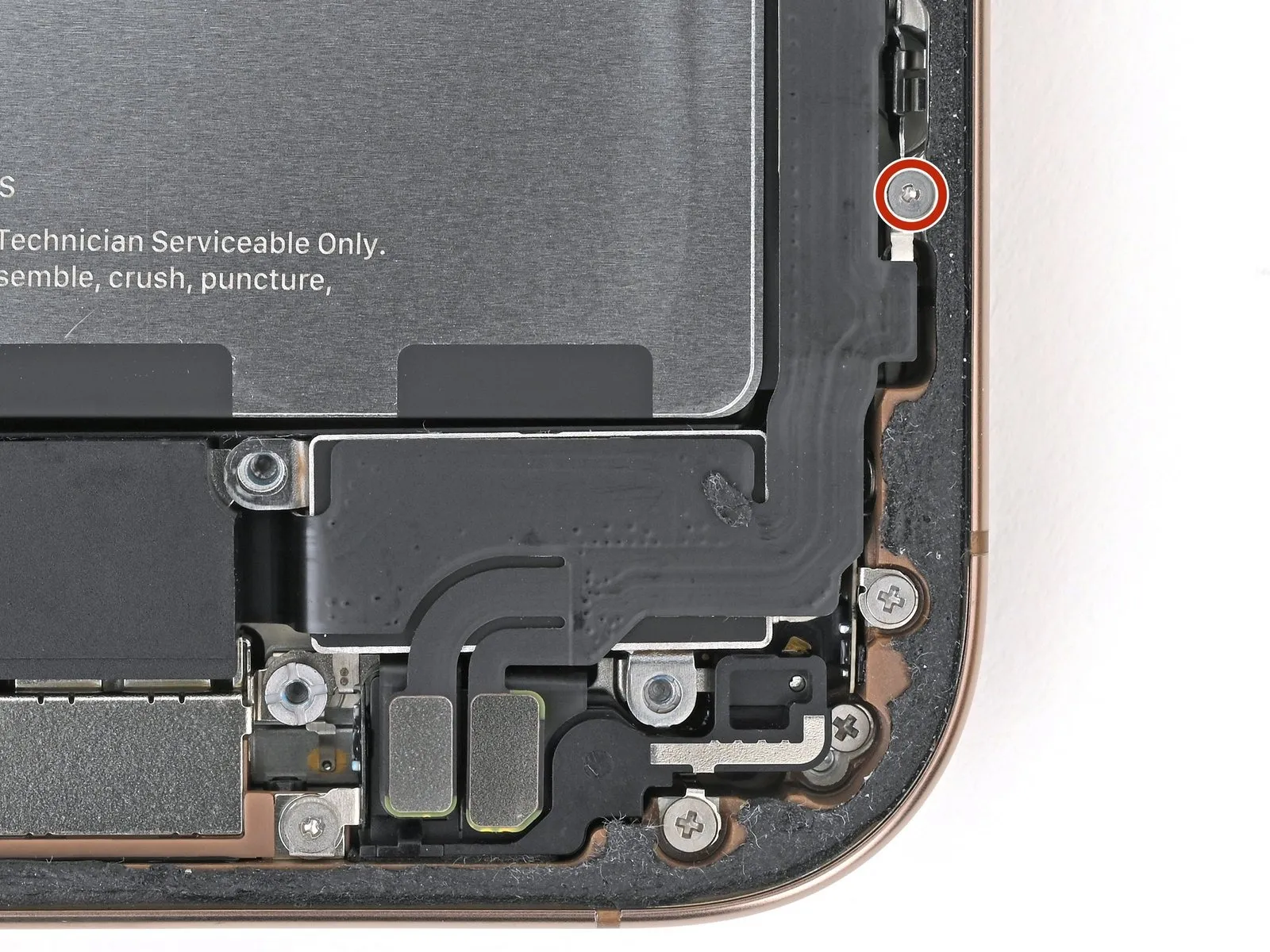
Step 19 | Disconnect the back glass

- Employ a Y000 tri-point screwdriver to detach the four screws that hold the upper connector cover in place.
- Use two.One millimeter.Utilize screws with a length designated as "long."
- Begin the process by performing action one.One point two millimeters.Utilize a screw with a substantial length.
- Begin the process by executing the action designated as "One."One point six millimeters.Employ a screw with a substantial length.
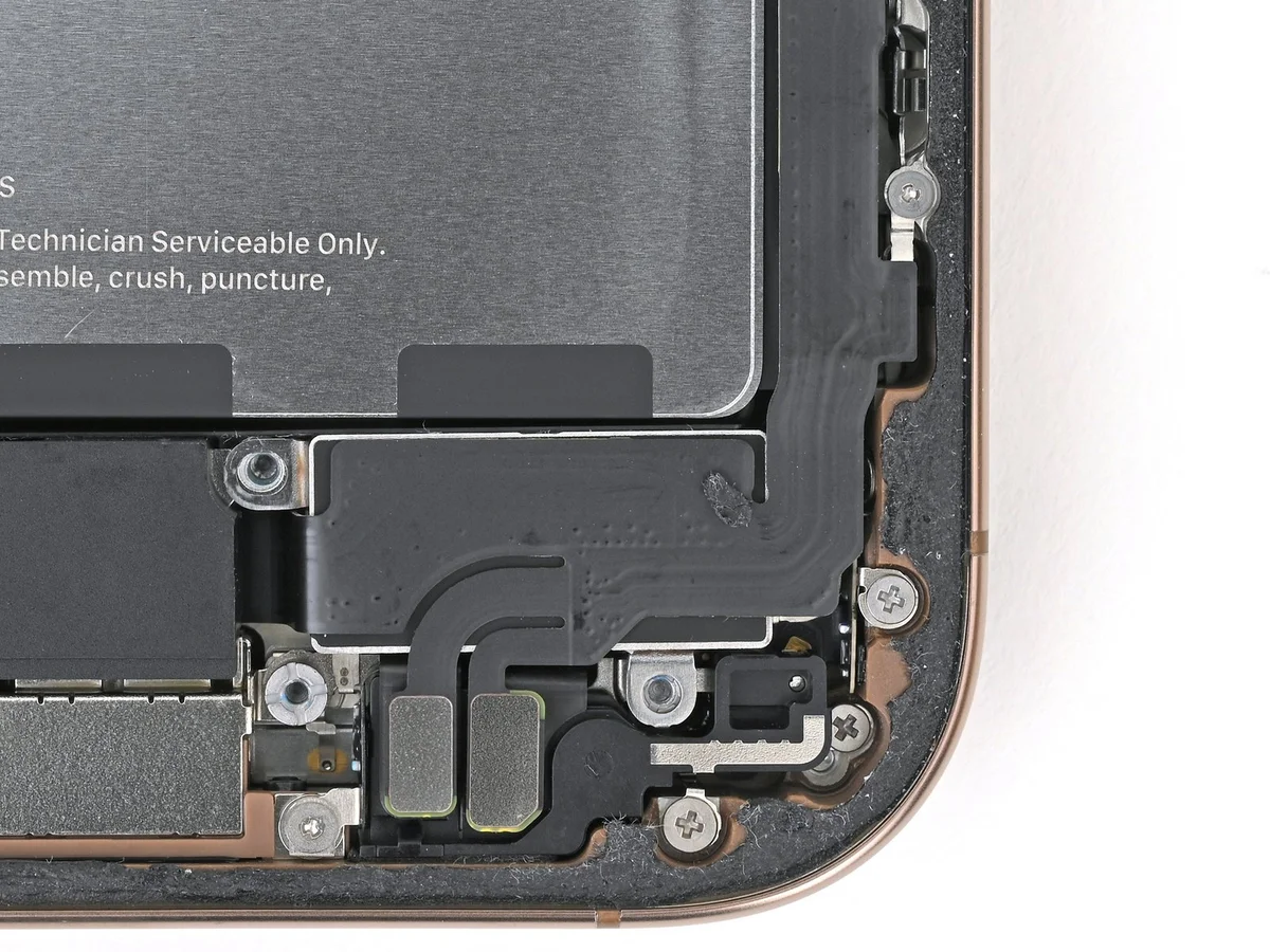
Step 20

- Employ the specified tool to perform the action.Employ fine-tipped pliers or similar precision instruments.orUse your hands.Gently lift and detach the upper connector cover.
Step 21
Step 22 | Remove the back glass

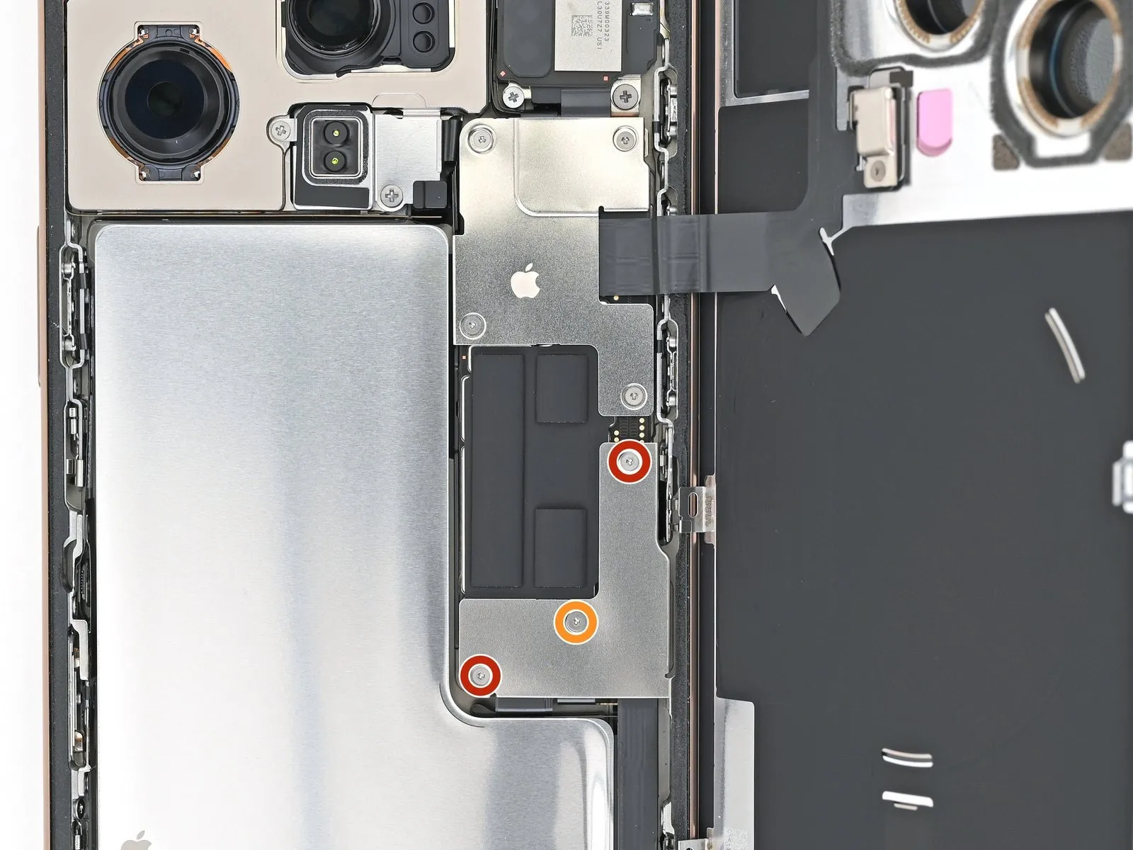
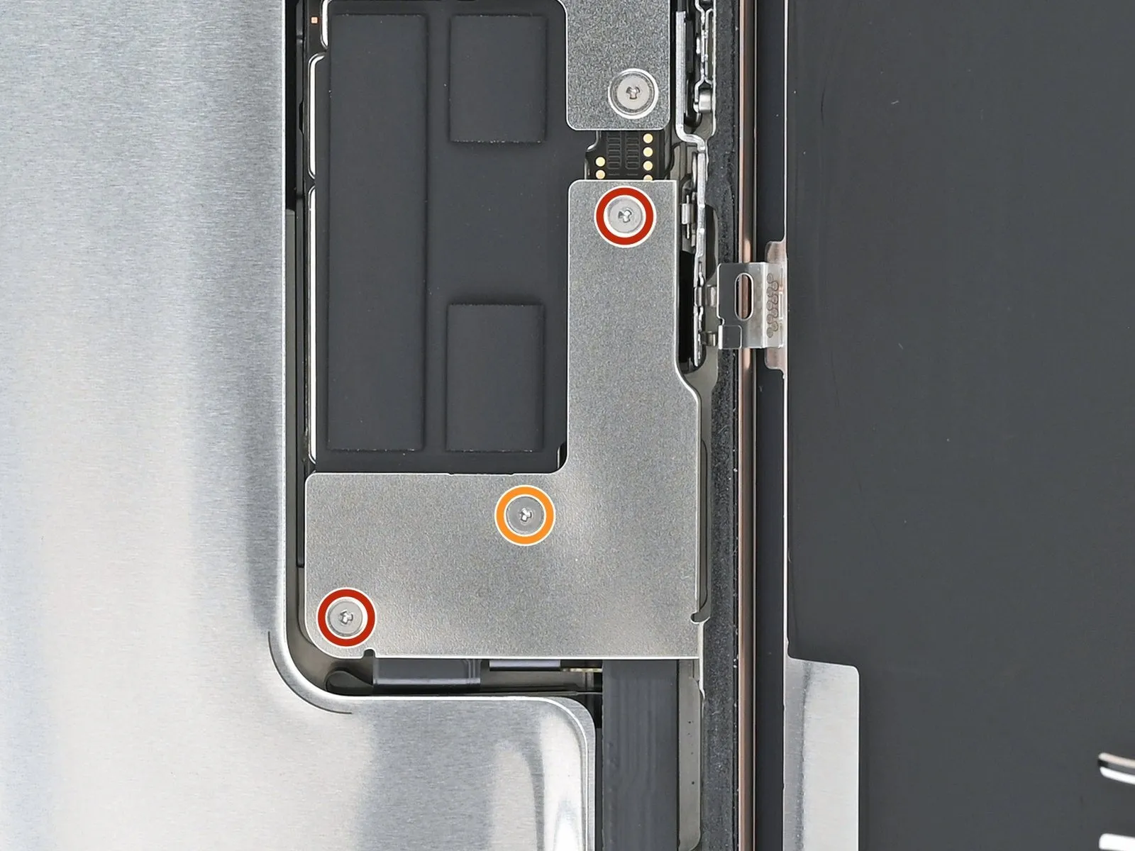
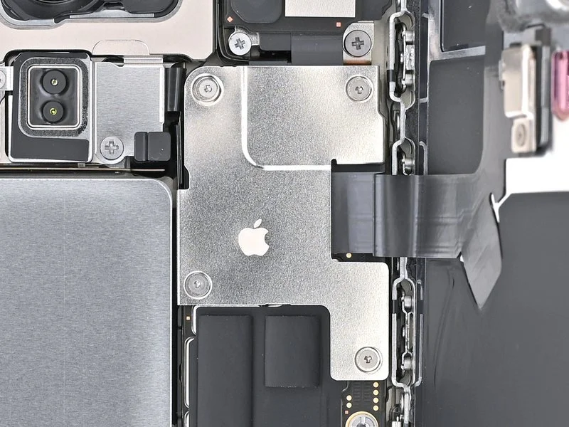
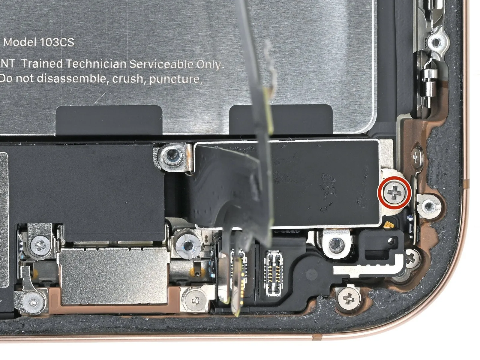
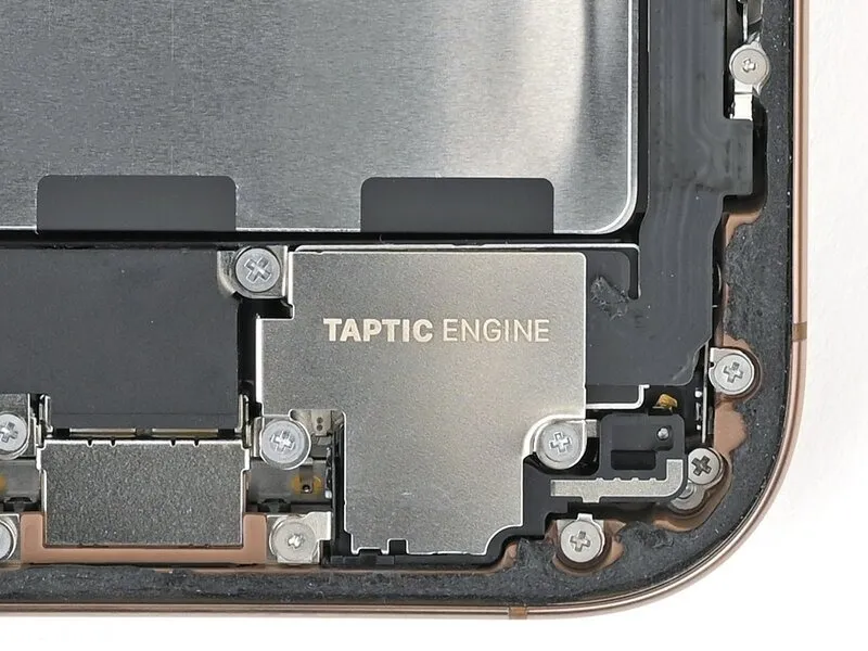
Step 23 | Remove the Taptic Engine cover

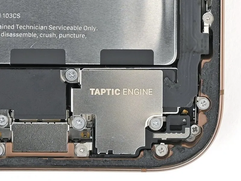
- Begin the process by performing action one.A screw measuring 3.0 millimeters in length.
- Two.Screws measuring 1.7 millimeters in length.
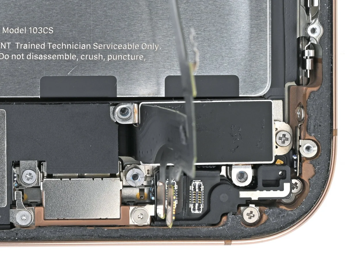
Step 24
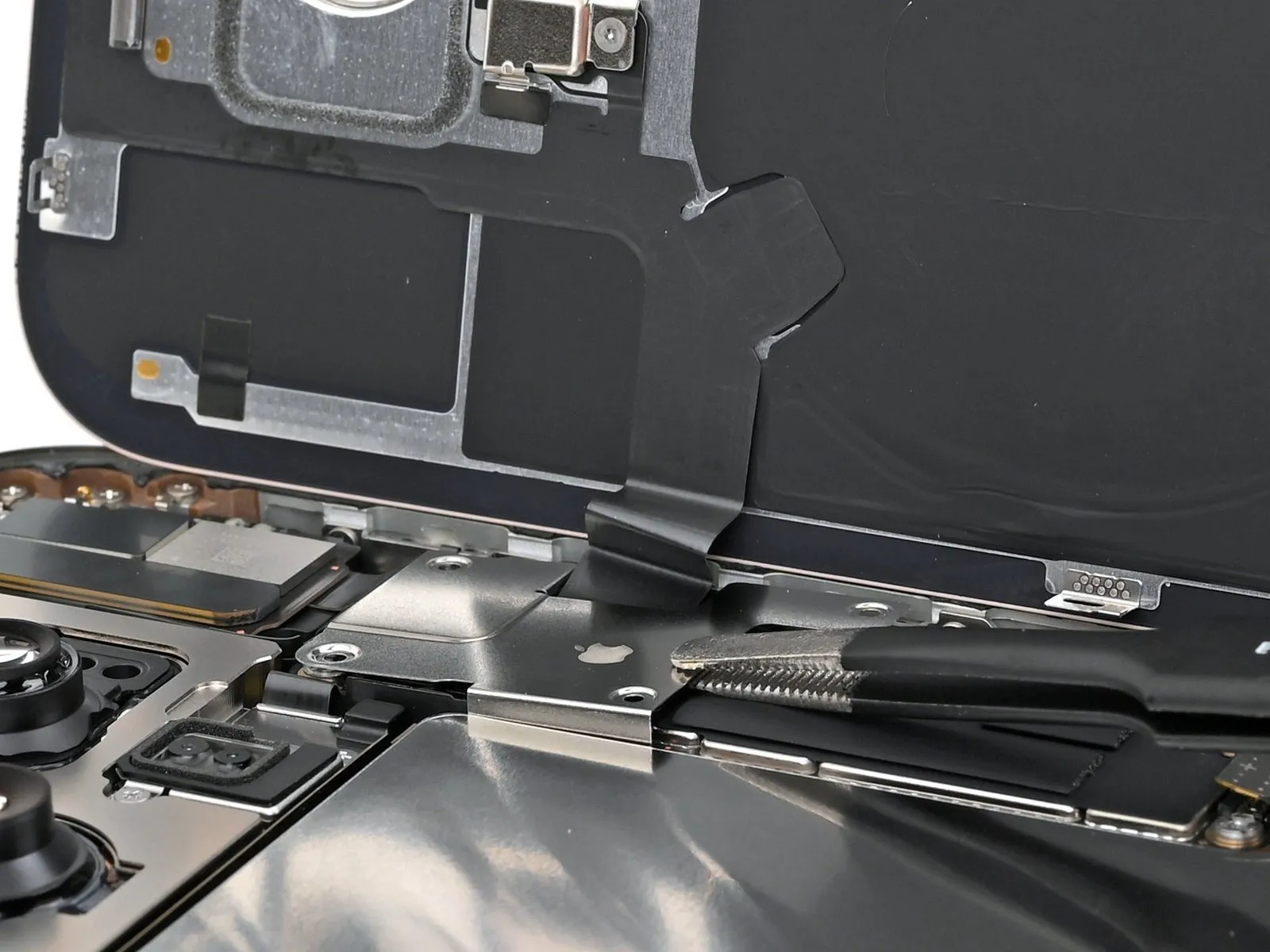
- Carefully raise the Taptic Engine cover's upper border using tweezers or your fingertips.
- After releasing the lower edge from the frame's securing latches, detach the Taptic Engine cover.
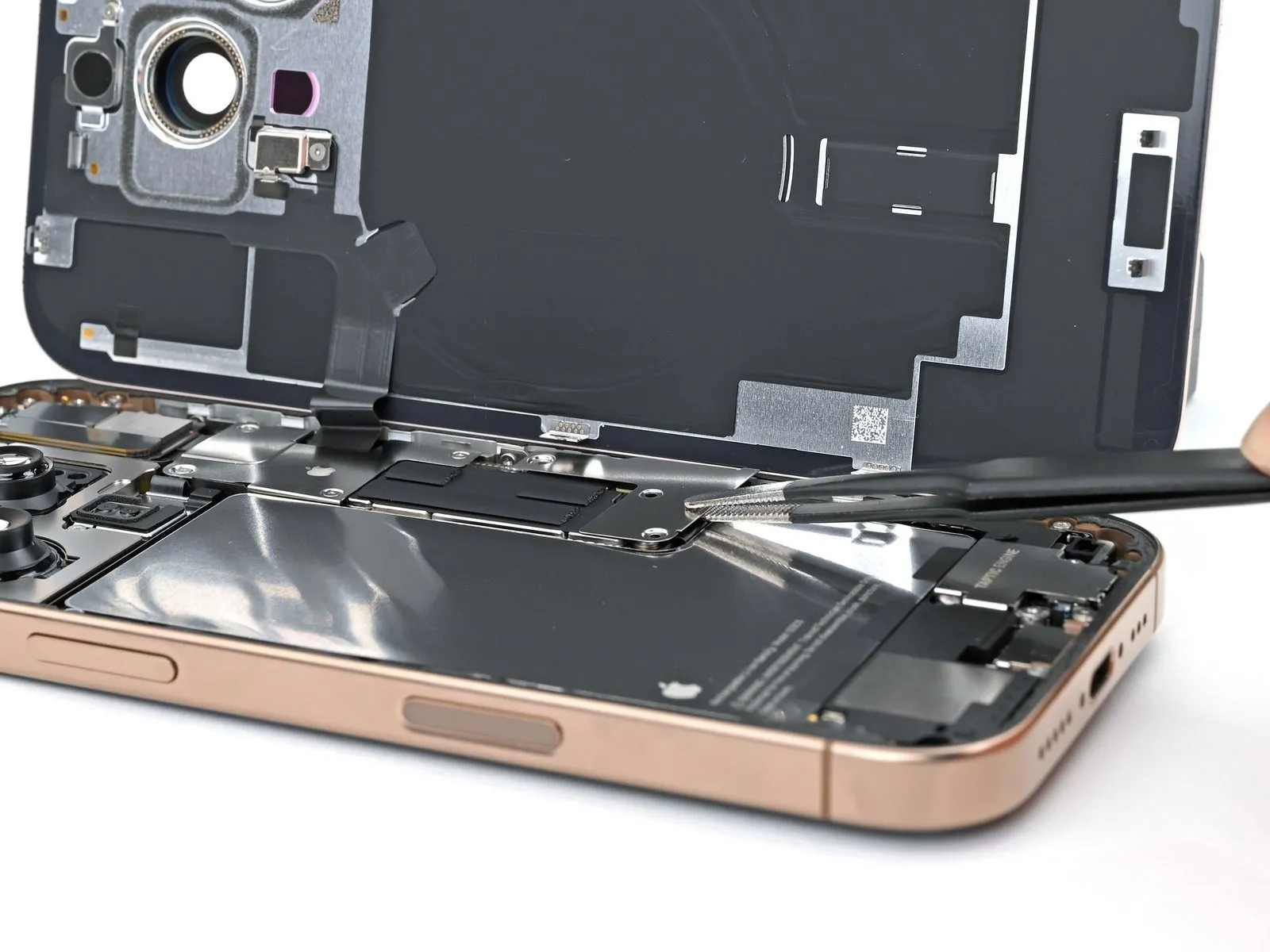
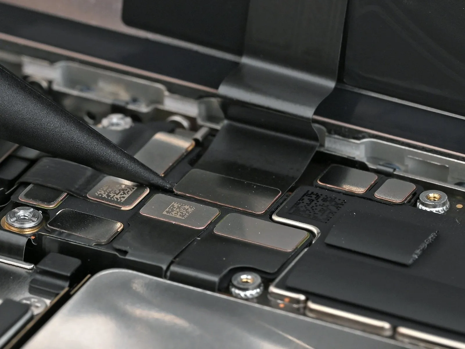
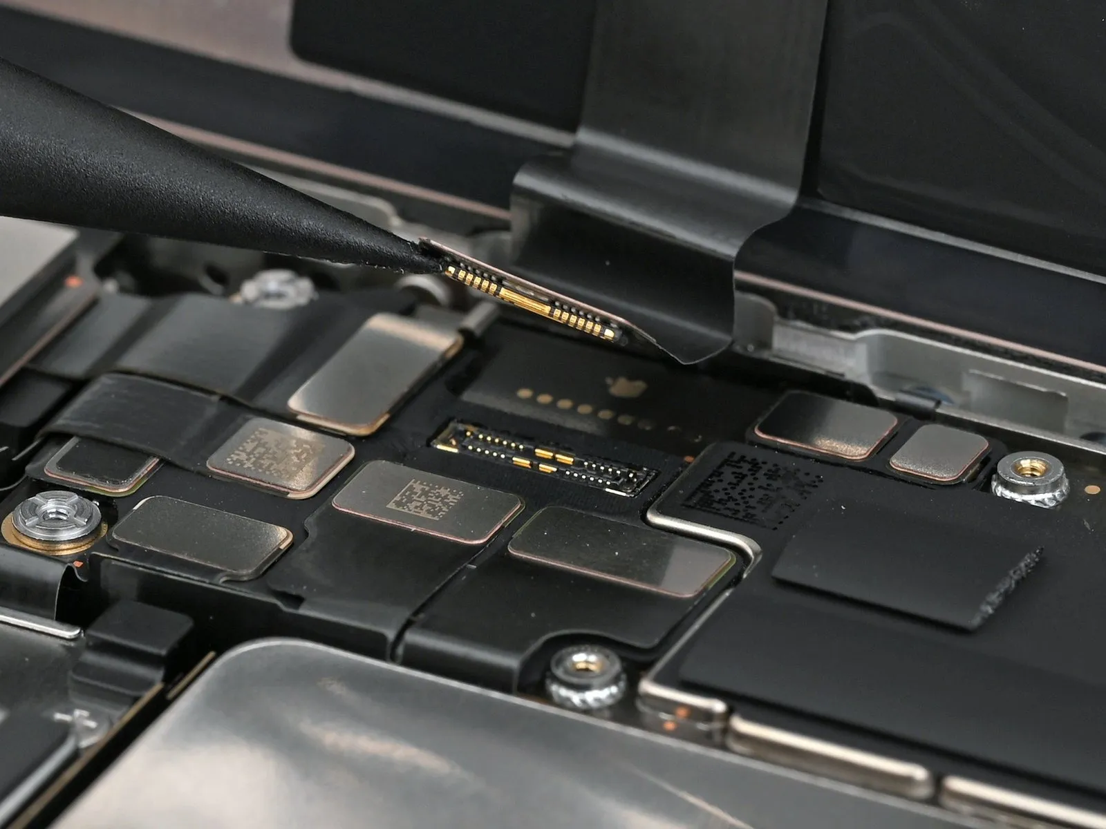
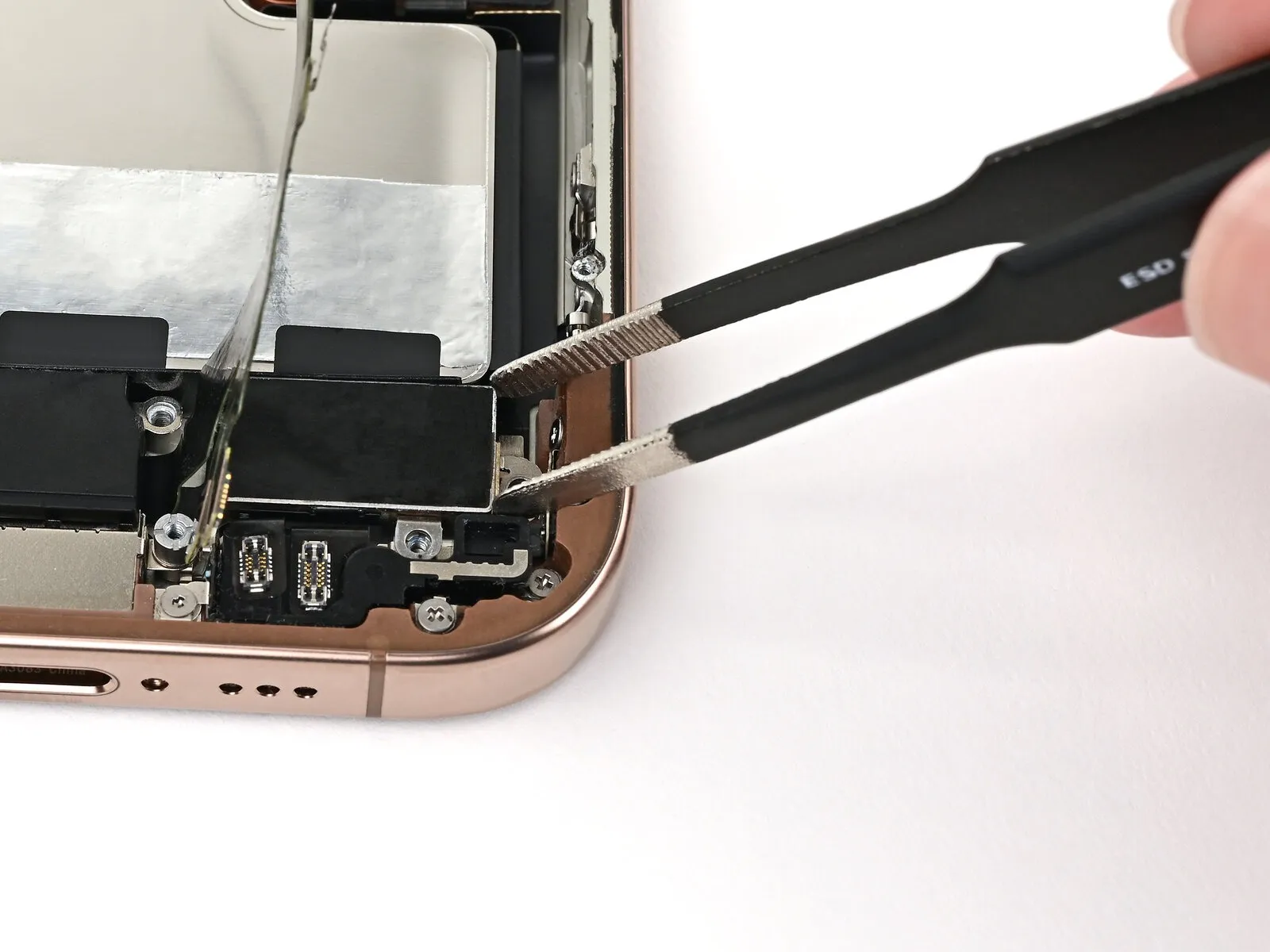
Step 25 | Disconnect the lower assembly cable
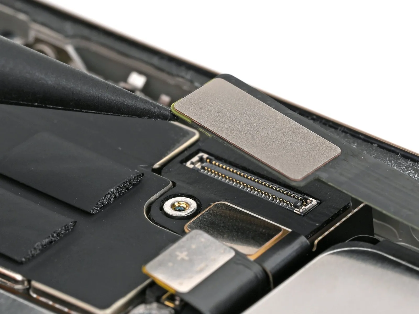
- Carefully insert the tip of a screwdriver to.Use a plastic pry tool, often referred to as a spudger.Using a prying tool, release the lower assembly cable connector from the logic board.
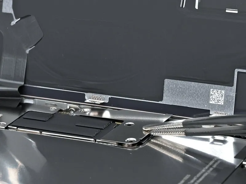
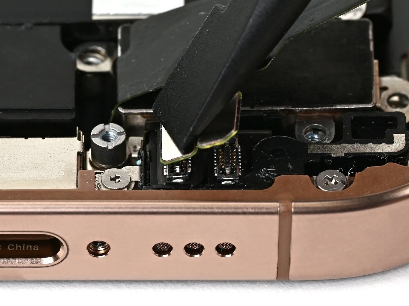
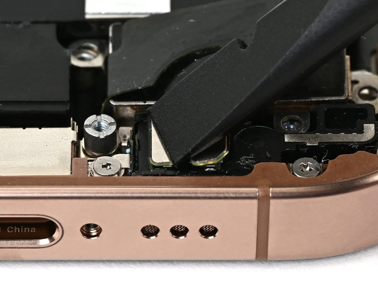
Step 26
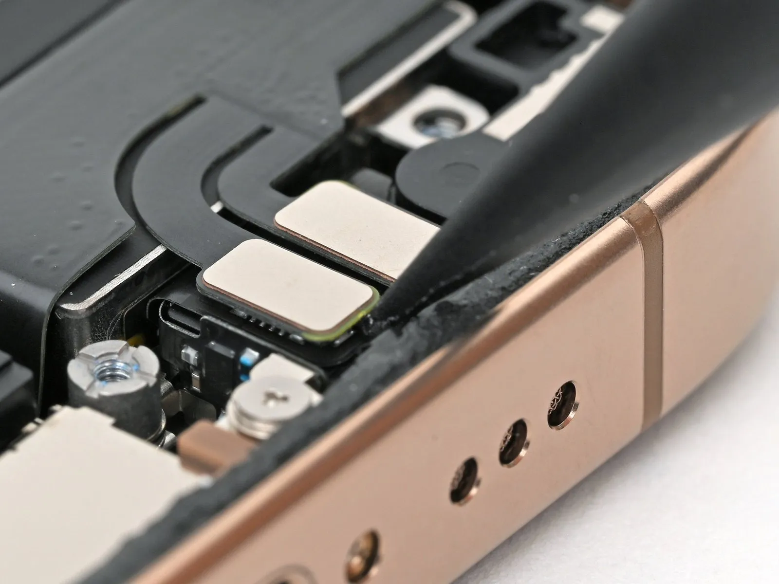
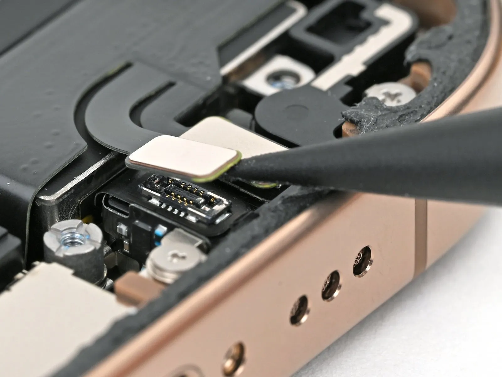
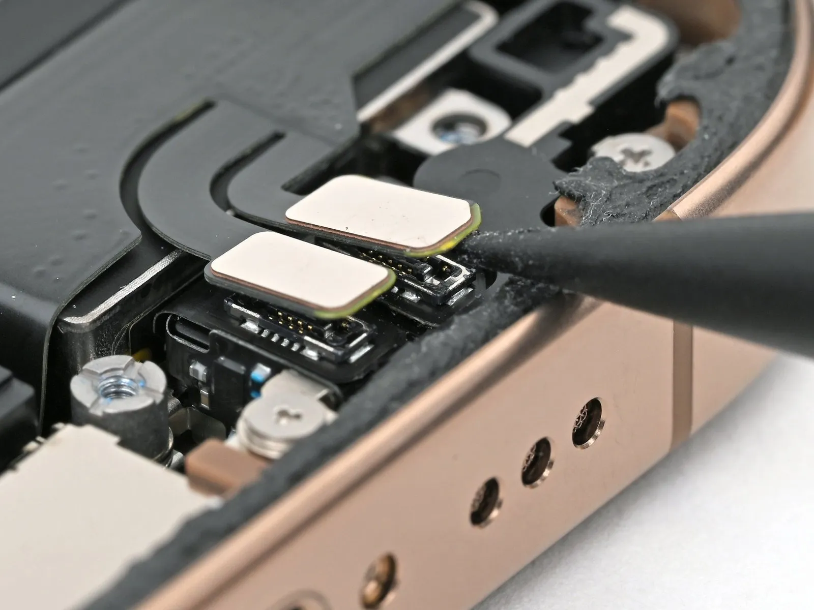
- Carefully employ the tip of a screwdriver to apply pressure.Use a plastic pry tool, often referred to as a spudger.Using a prying tool, carefully separate and detach the two press connectors located on the lower right side of the frame.
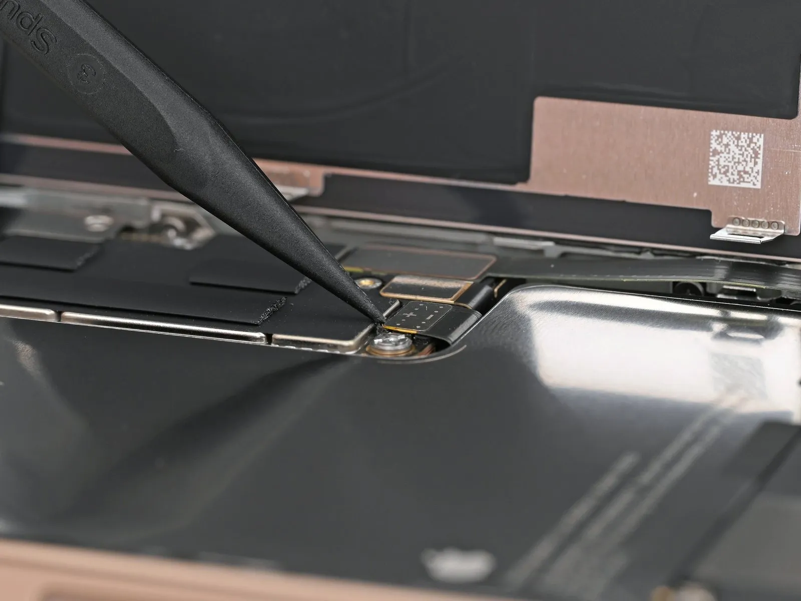
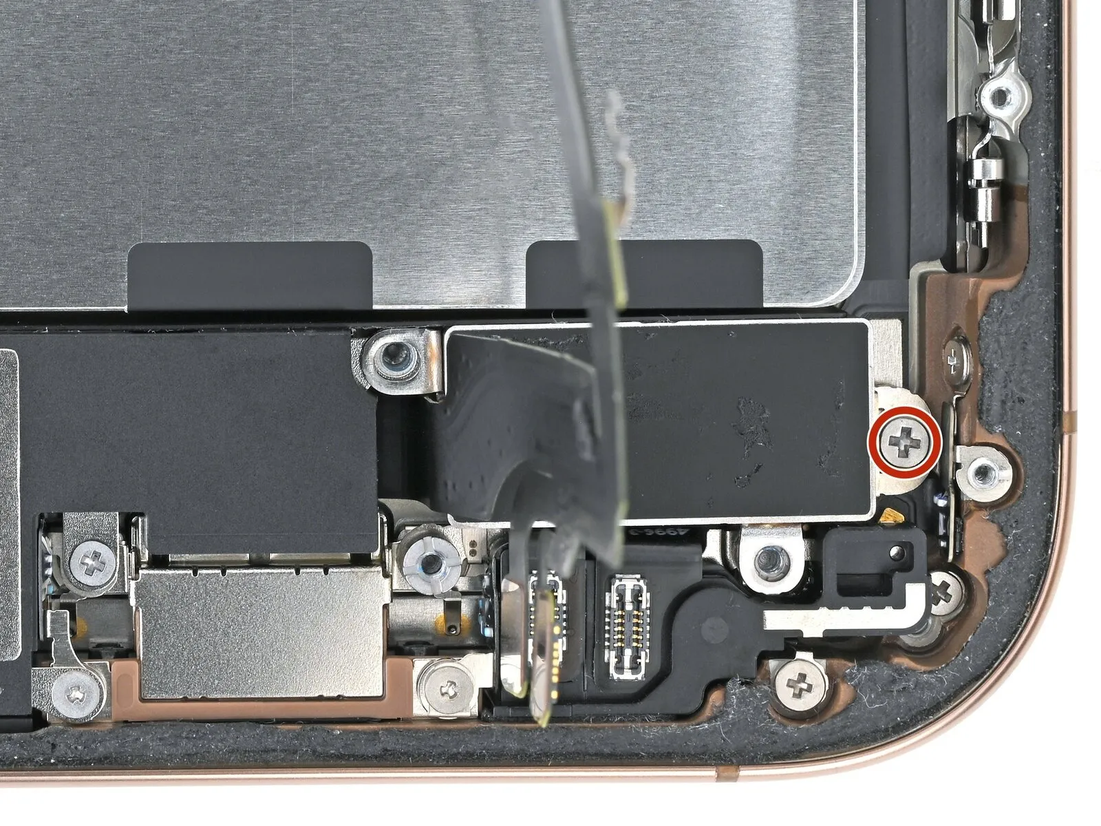
Step 27
- Employ a Y000 tri-point screwdriver for removal.One millimeter.A lengthy screw fastens the cable to the lower assembly.
Step 28
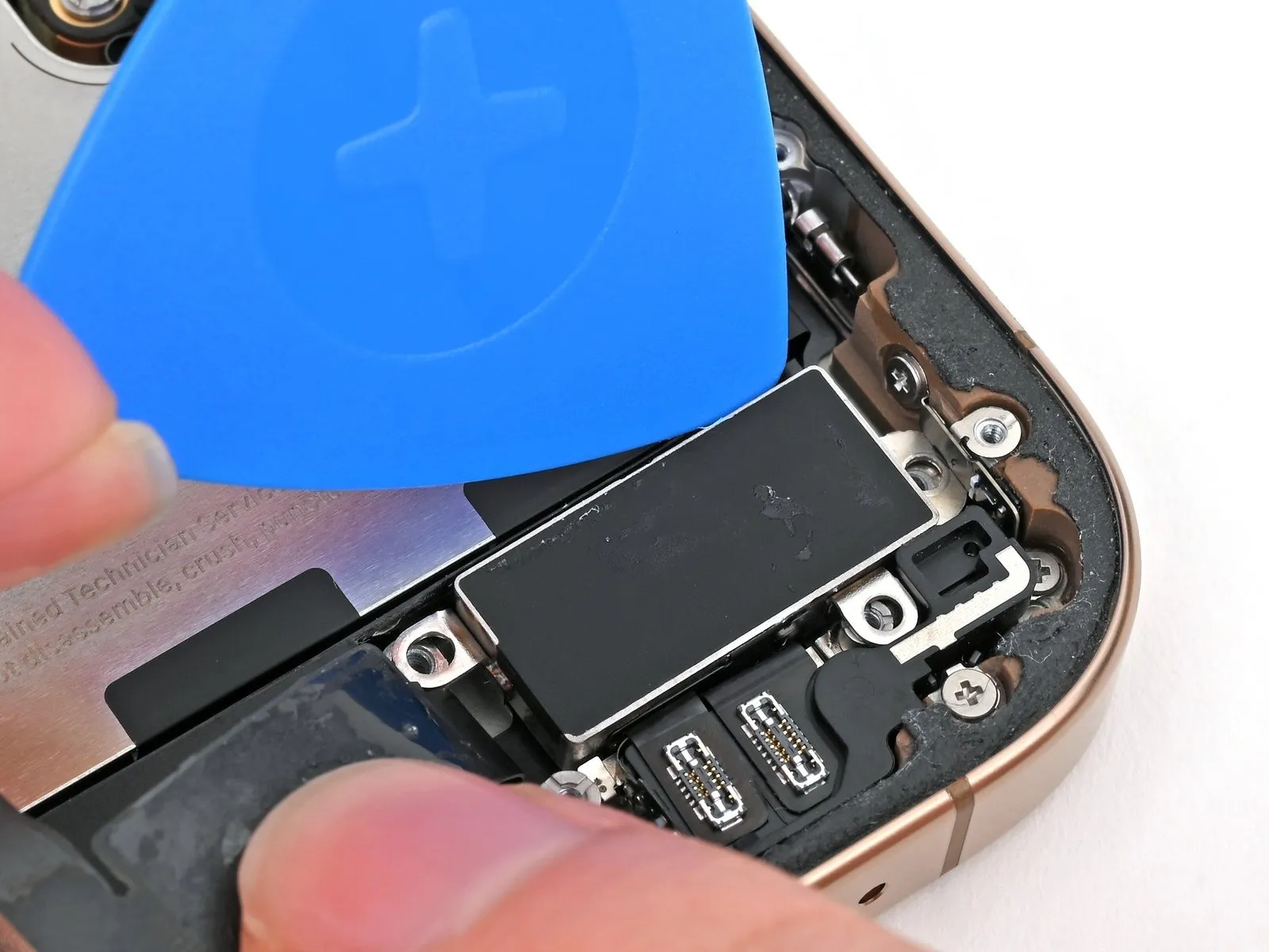
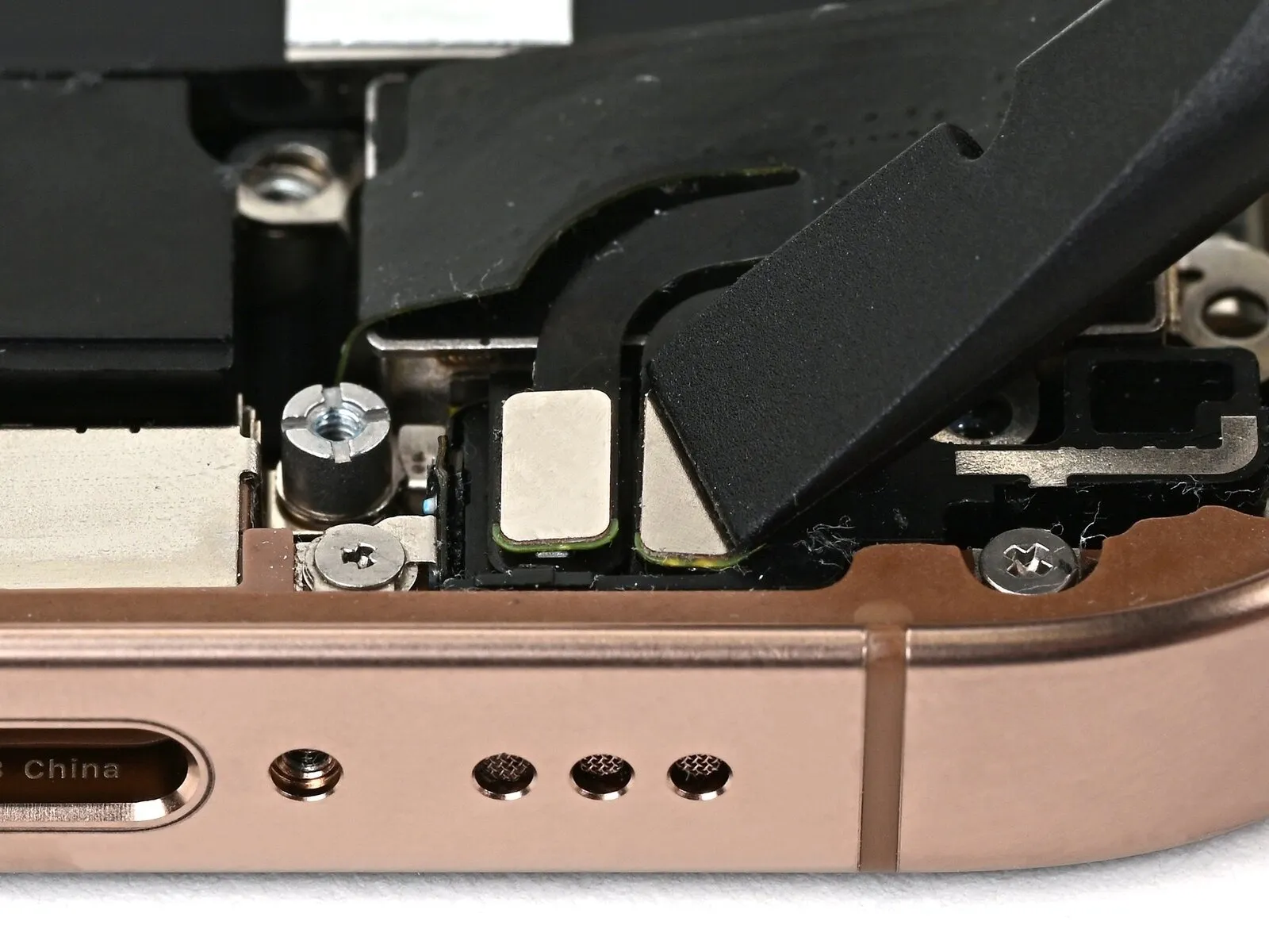
- Apply heat to the lower assembly's cable area situated above the Taptic Engine, using either an iOpener or a hair dryer, until the surface reaches a temperature that is noticeable upon contact.
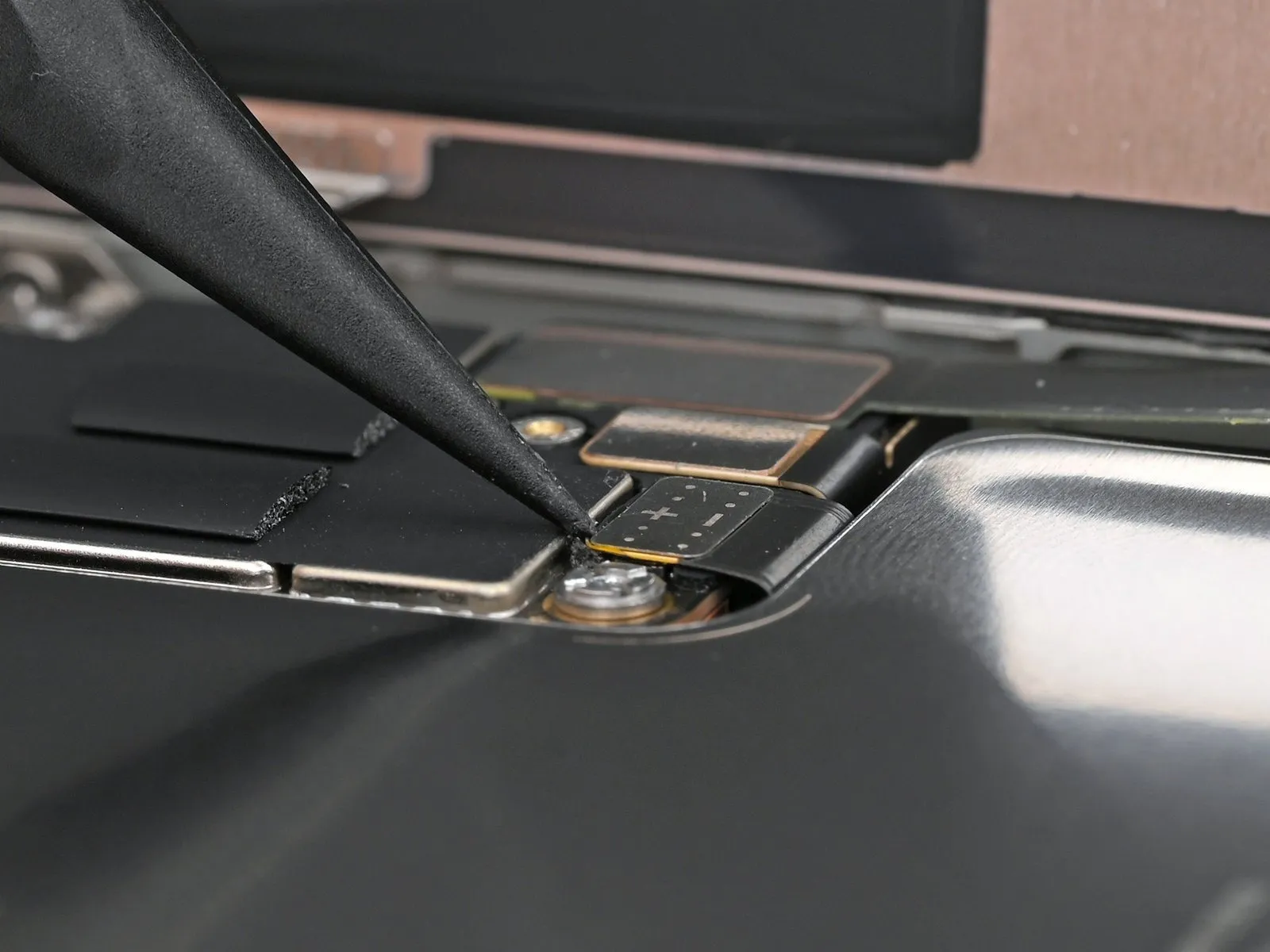
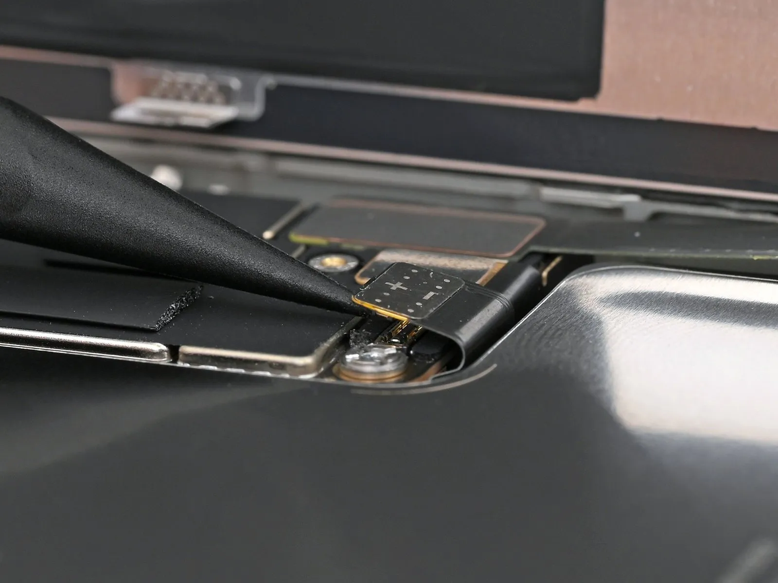
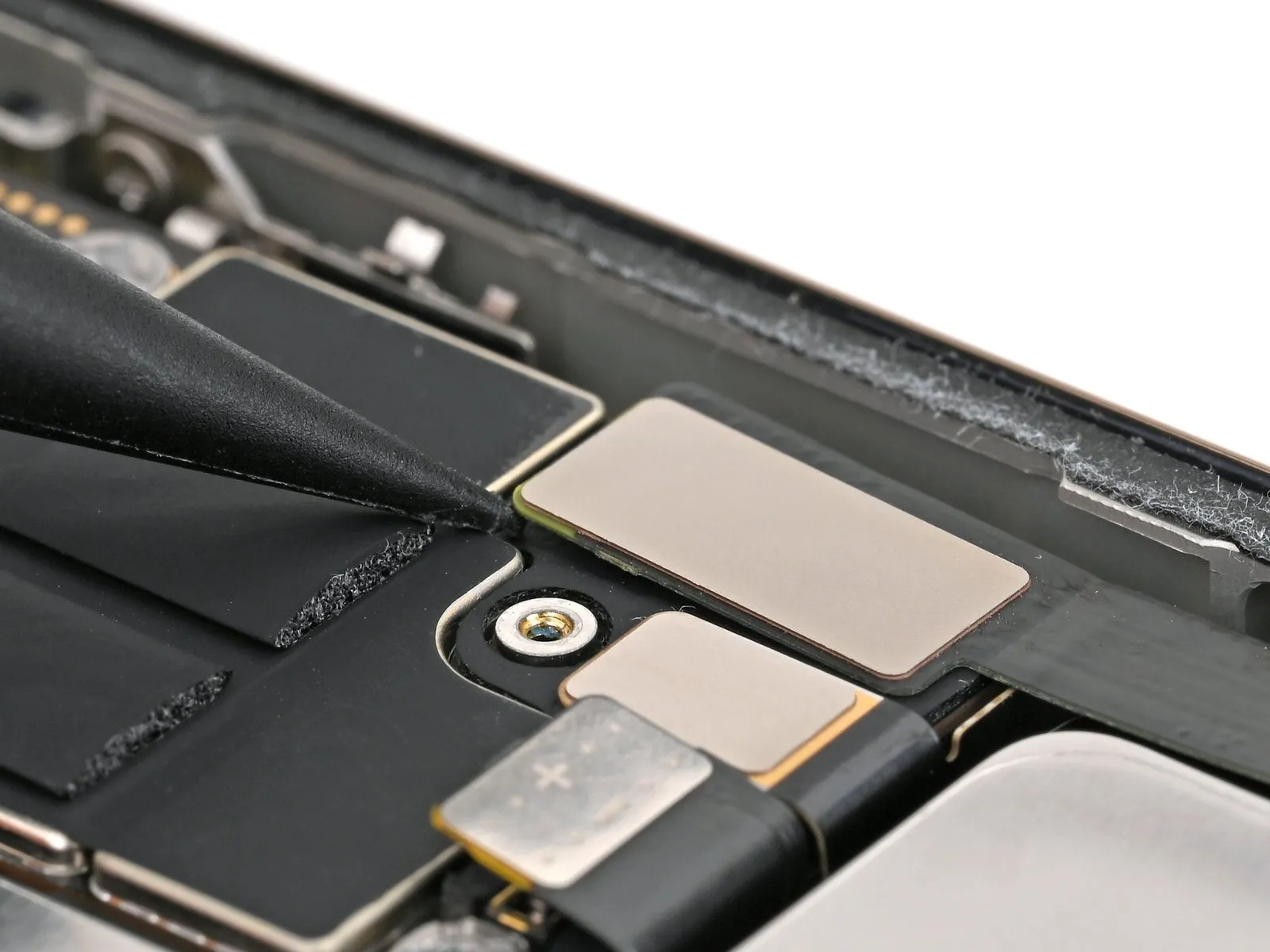
Step 29
- Using an opening pick, gently disengage the lower assembly cable by sliding the pick between the cable and its attached component.The device incorporates a Taptic Engine..
- To gain access, gently maneuver the cable, ensuring it's clear of the work area.The device incorporates a Taptic Engine..
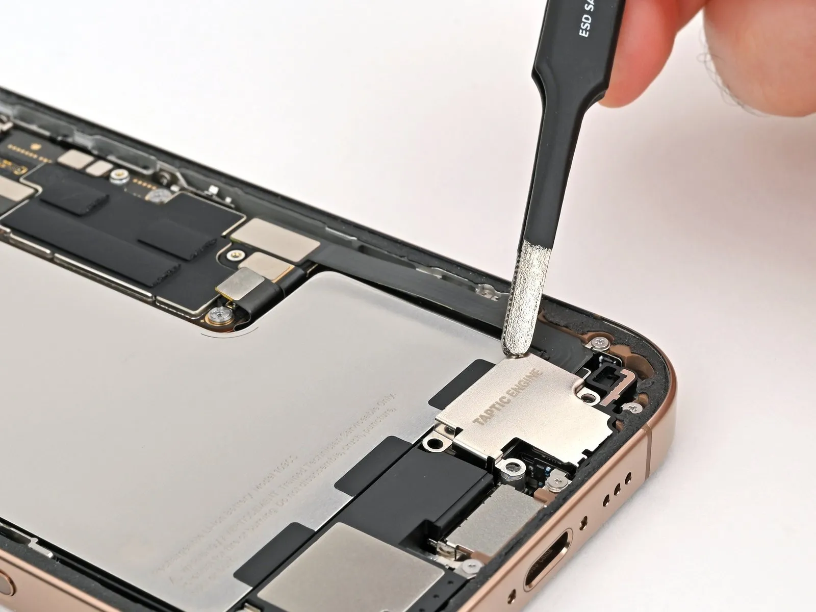
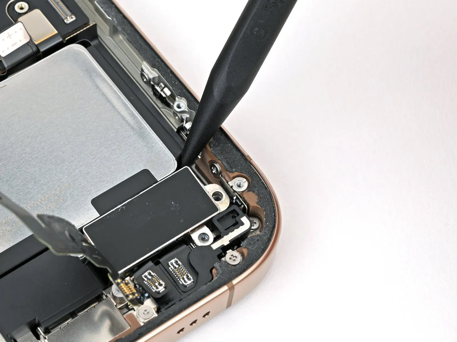
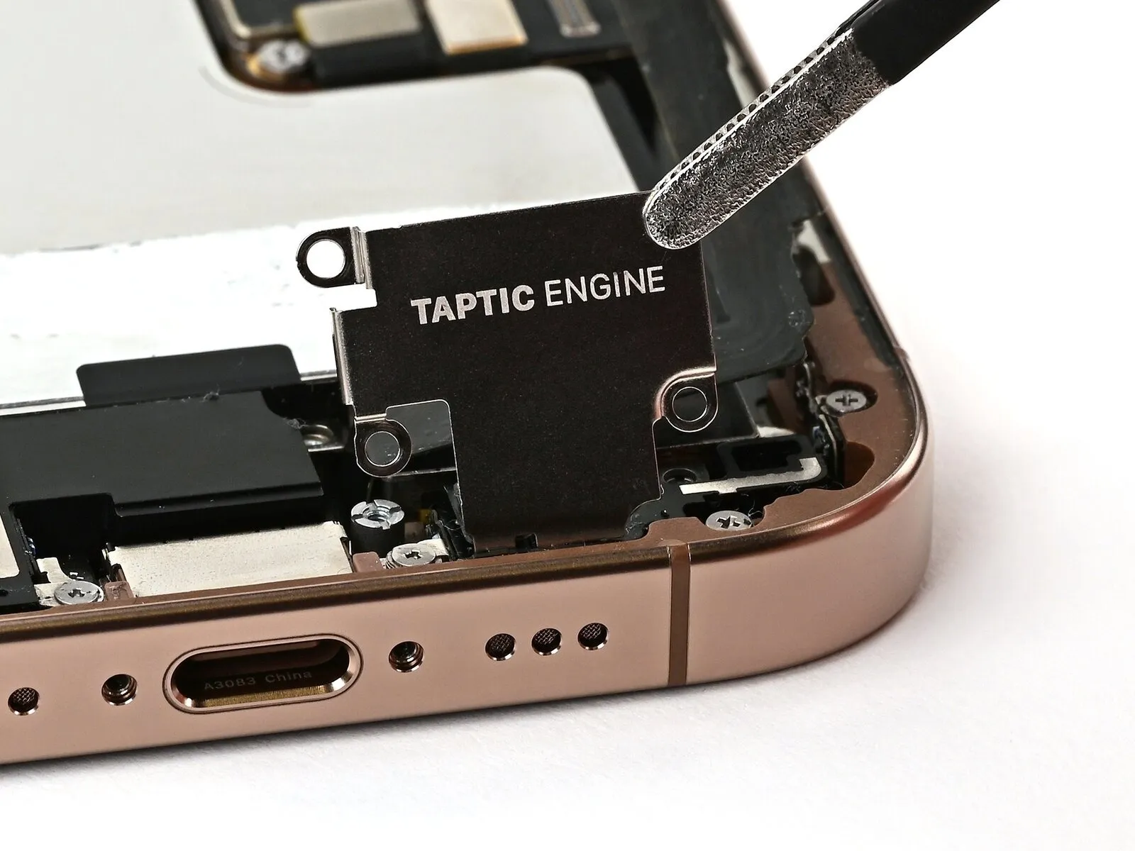
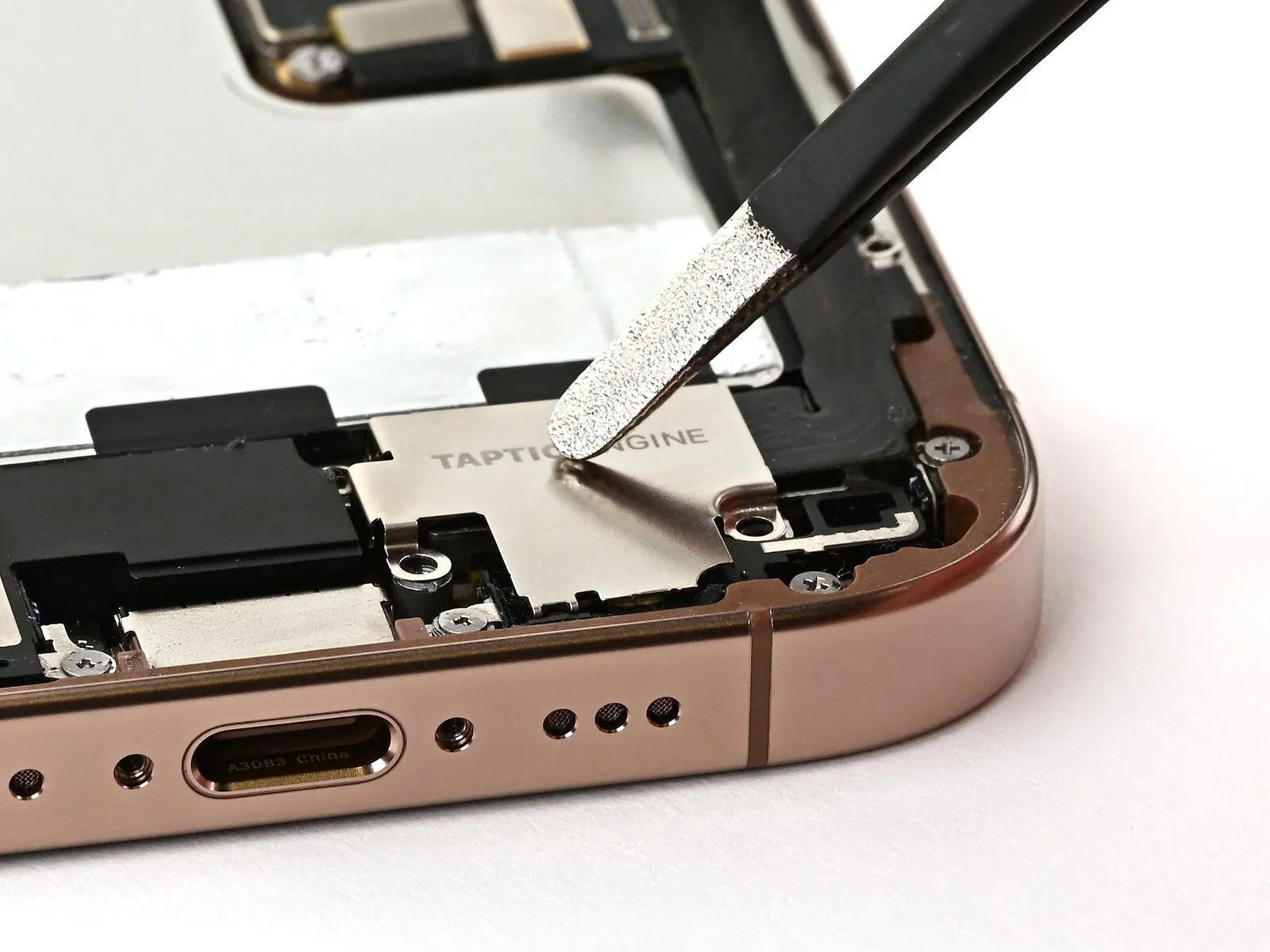
Step 30 | Remove the Taptic Engine
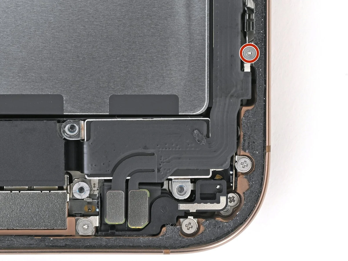
- Employ a Phillips screwdriver to detach theA screw measuring 1.9 millimeters in length.Ensure the component is firmly fixed.The device incorporates a Taptic Engine..
Step 31

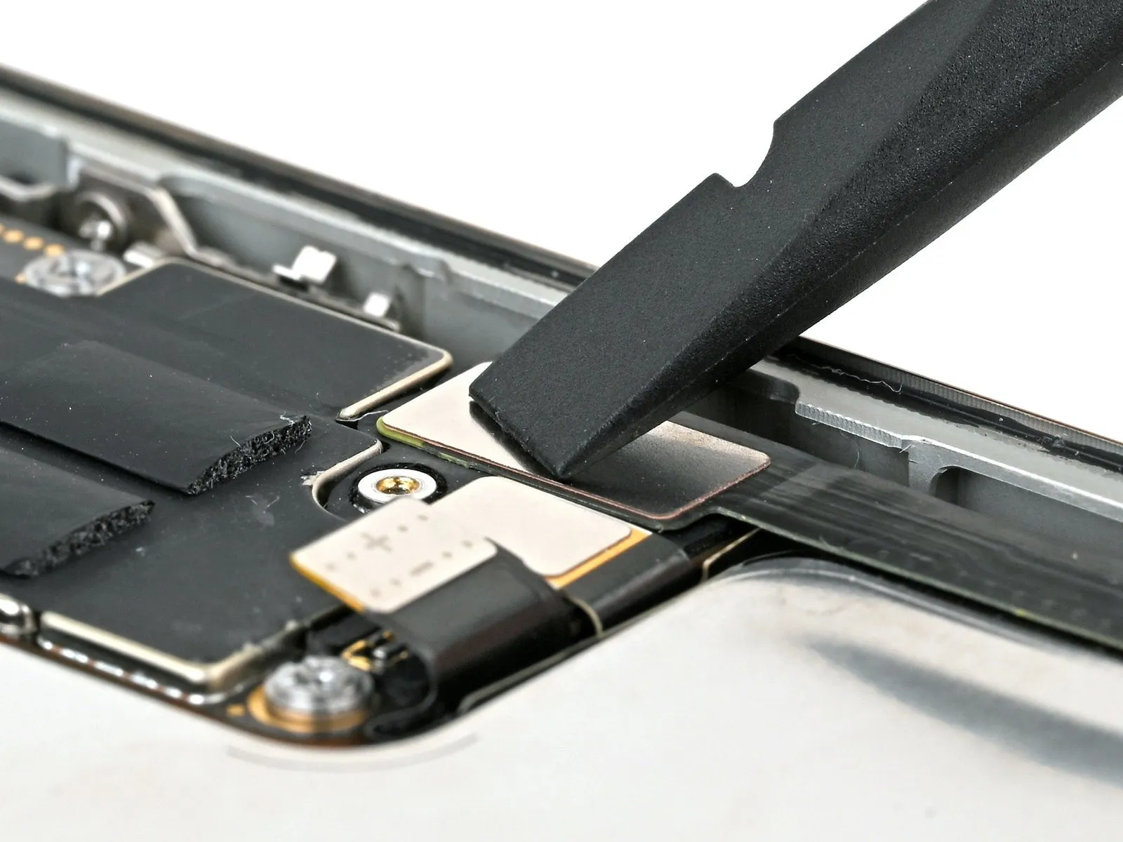
- Carefully insert the pointed end of a prying tool beneath the upper border.The device incorporates a Taptic Engine.Carefully detach the plastic buffer strip, which is affixed to the component.
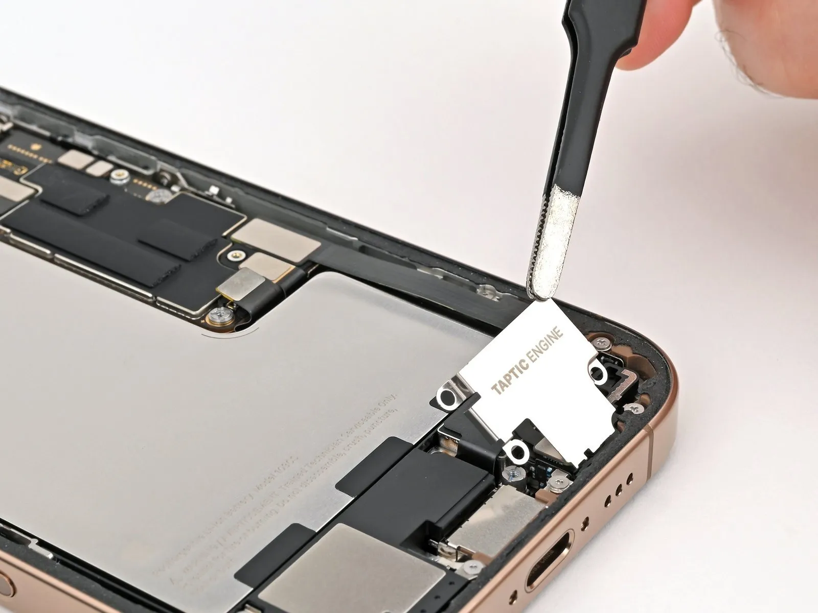
Step 32
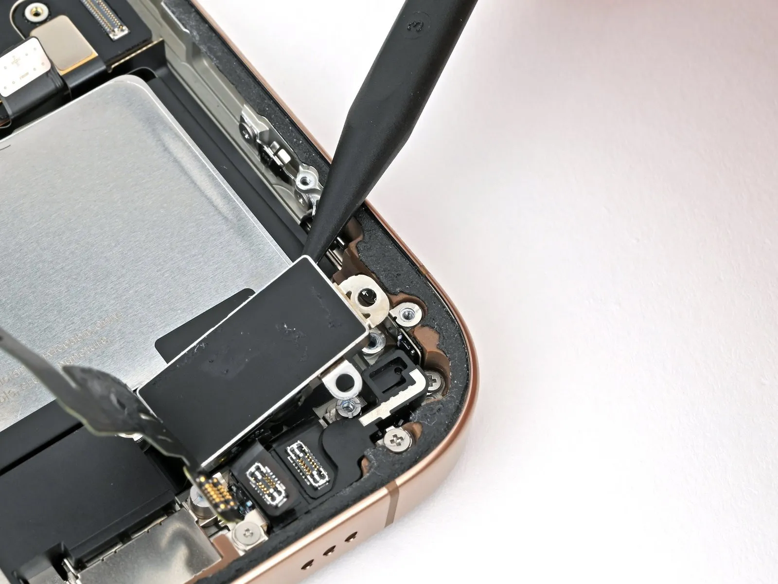

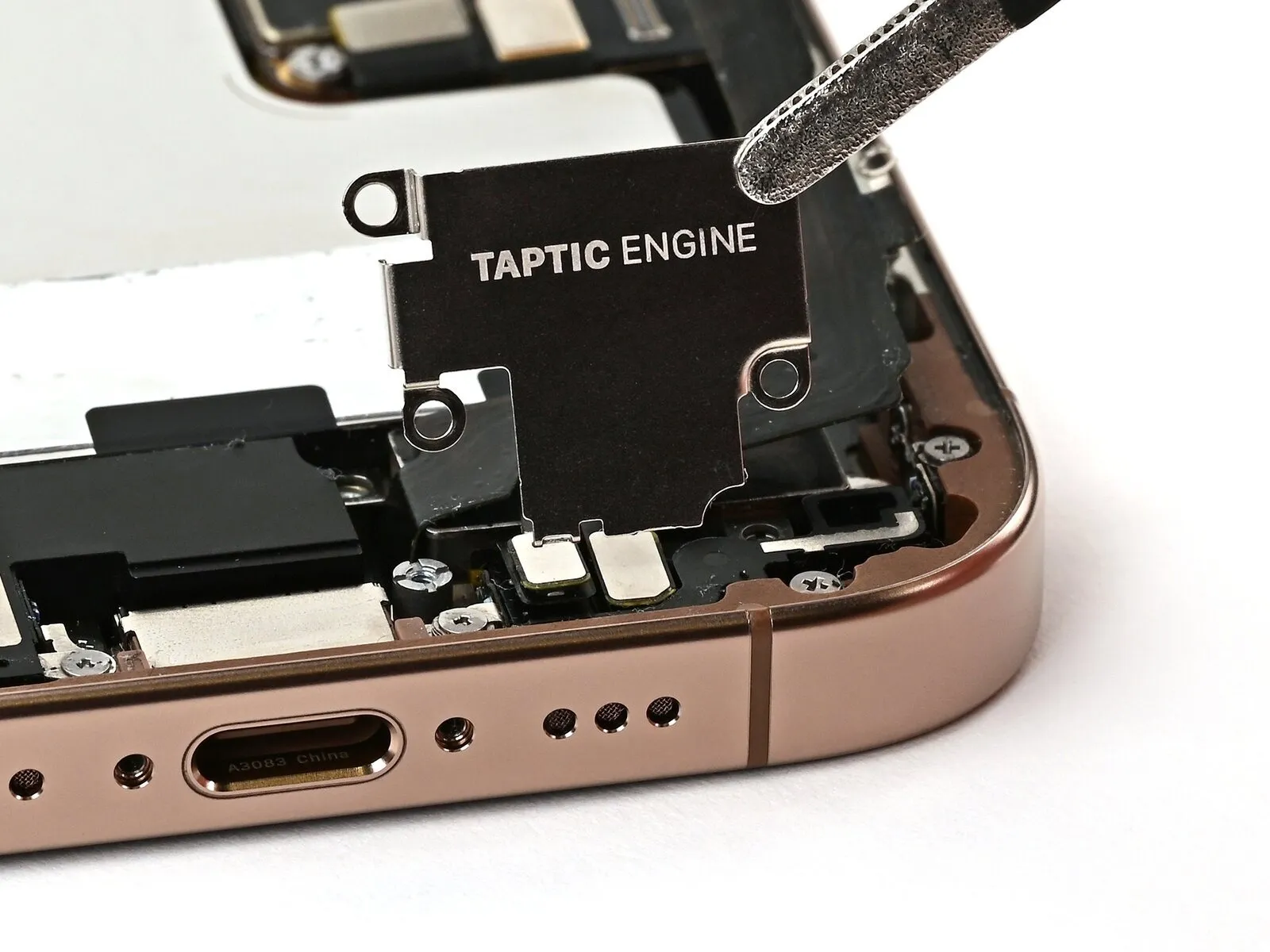
- Carefully lift the component using a spudger tip.The device incorporates a Taptic Engine.Begin the removal process by grasping the component at its upper-rightmost point.
- Avoid applying force that could damage the battery during separation.
- Using the appropriate wrench, disconnect the component, ensuring all associated fasteners are released and the specified dimensions remain unaltered.The device incorporates a Taptic Engine..
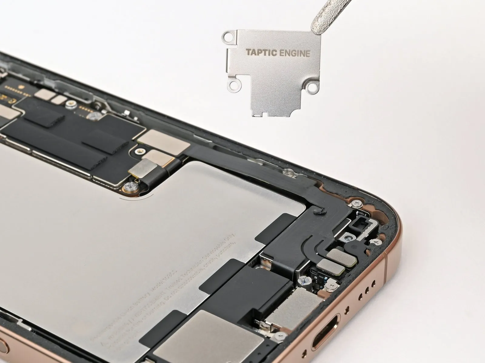
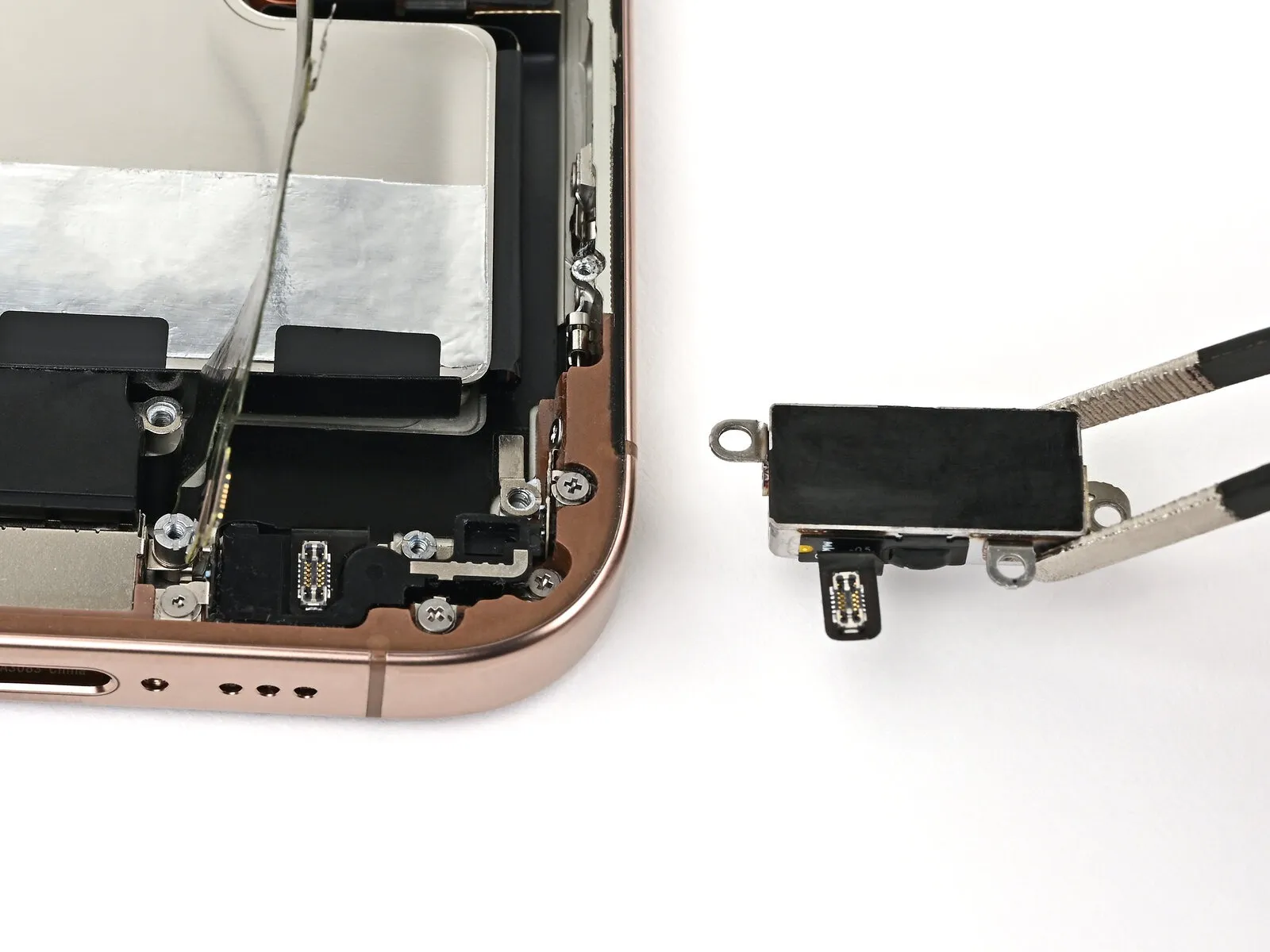
Step 33 | Disassembly complete

Step 34 | Install the Taptic Engine
- Employ the specified tool to perform the action.Use tweezers with a flat, rounded tip.Carefully position the Taptic Engine so its screw posts match the frame's corresponding holes, ensuring proper alignment before securing it.
Step 35

- Employ a 3/8-inch socket wrench to loosen the retaining bolt, ensuring you apply consistent pressure to prevent damage to the threaded stud and observe the caution regarding eye protection.Use a Phillips-head screwdriver.Secure the component using the specified fasteners, ensuring proper alignment as indicated by the dimensions and tolerances detailed in the parts list.A screw measuring 1.9 millimeters in length.Affix the Taptic Engine, positioned along the device's right side.
Step 36 | Connect the lower assembly cable
- Carefully engage the two lower assembly press connectors by applying pressure with a finger or spudger.
To install these press connectors, carefully position each one directly above its corresponding socket, then apply downward pressure sequentially to each side until you hear a distinct click confirming secure engagement; avoid excessive force, and if initial attempts fail, realign the connector before retrying.
Step 37

Employ a Y000 tri-point screwdriver for this step.Secure the component using the specified fasteners, ensuring proper alignment as indicated by the dimensions and tolerances detailed in the parts list.A screw measuring 1.0 millimeters in length.Affix the cable to the lower assembly.
Step 38

Employ either a fingertip or a spudger.Secure the lower assembly cable by firmly seating its connector into the designated receptacle on the logic board's bottom-right corner.
Step 39 | Install the Taptic Engine cover
- Employ either tweezers or your fingertips to manipulate the component.Secure the Taptic Engine cover in place.
- Verify that the cover’s lower edge engages securely with the retaining mechanism.Secure the component to the frame.
Step 40

Employ a screwdriver with a Phillips head.Secure the Taptic Engine cover with the three screws, ensuring each is properly tightened.
- A screw, measuring 3.0 mm in length, is required.
- Use two screws, each measuring 1.7 millimeters in length.
Step 41 | Remove the leftover adhesive


- Employ the specified tool to perform the action.Use tweezers with a flat, unpointed tip.Use your fingers to detach sizable adhesive sections from the frame's edges.
- Employ a 3/8-inch socket wrench to loosen the fastener, ensuring you apply even pressure to avoid damaging the retaining clip and following all safety precautions outlined in section 4.2 regarding potential pinch points.Use a plastic pry tool, often referred to as a spudger, to avoid scratching surfaces.Carefully remove any remaining adhesive from the frame's surface using a scraper.
- To loosen a firmly adhered adhesive, utilize heat.Utilize a device designed to emit warm, directed airflow, ensuring the unit’s wattage is no greater than 1500W and its cord is undamaged, to gently warm the component.orApply warmth using a device that generates heat, ensuring the temperature does not exceed 200°F (93°C) to prevent damage.Repeat the process.
Step 42 | Clean the back glass


Step 43 | Clean the frame

- Using a cloth, remove any remaining adhesive from the frame's edges by wiping consistently in a single direction.
- Careful execution is essential; a thoroughly cleaned frame surface enables uniform application of the replacement adhesive, which is critical for optimal bonding.
Step 44 | Apply the replacement adhesive

- Carefully observe the frame's features—including the camera opening and indentations at the top and bottom—to guide the adhesive placement.
Step 45


- Because the adhesive surface is highly adhesive, avoid contact with other materials until you are prepared to bond it to the frame.
- Remove the protective layers from the adhesive until the surface designed to bond with the frame is revealed.
Step 46


- Because the adhesive bonds immediately upon contact, any adjustments after placement are impossible; instead, removal and replacement with fresh adhesive are required.
- Ensure proper positioning, then apply even pressure to secure the adhesive strip against the frame.
Step 47


- Proper adhesive placement ensures the borders seat flush and precisely.
- Carefully reposition any slight adhesive misalignments by gently drawing the extended borders toward the frame.
- Should the adhesive develop creases or wrinkles, discard the affected material and reapply with a new portion of adhesive.
- Should a replacement set of adhesive strips be unavailable, the iPhone can be reassembled and operated without them; however, be aware that the device's water resistance will be reduced until the adhesive is properly replaced.
Step 48


- Exercise caution to avoid damaging the delicate grounding clips; should one become displaced, carefully reposition it using your fingers or tweezers.
- Apply gentle pressure to avoid distorting or overextending the adhesive material.
Step 49


- Employ a 3/8-inch socket wrench to loosen the retaining bolt, ensuring you maintain a firm grip and avoid over-torquing the fastener to prevent damage, and then carefully detach the component.Use a plastic pry tool, often referred to as a spudger, to avoid scratching surfaces.Locate the pull tab, typically found at a corner, and use it to raise the large front liner, ensuring your fingers are positioned to facilitate this lifting action.
- Carefully separate the substantial adhesive front liner from its backing by grasping and lifting the designated pull tab.
- To avoid unintended adhesion during reassembly, a protective liner might still be in place around the edges; wait to peel back these small liners.
Step 50 | Connect the back glass

Using a repair tool, gently support the rear glass panel on its right side to prevent movement.
Step 51

Gently depress the component with your fingertip or the broad, planar end of a prying tool.Use a plastic pry tool, often referred to as a spudger, to gently separate components.Carefully align and secure the back glass connector to the logic board, ensuring a firm connection.
Step 52 | Connect the battery

- Employ a fingertip or a plastic spudger to apply gentle pressure.Use a plastic pry tool to gently separate.Align the battery press connector and apply pressure to secure it to the logic board.
- Before finalizing the iPhone's reassembly, verify the repair's functionality by powering on the device and confirming expected operation; then, turn it off again to proceed with the remaining steps.
- Attempt to power on the iPhone; if unsuccessful, establish a connection to a power source and repeat the power-on process.
- After installing a new logic board, if the display remains inactive, proceed with the subsequent steps.Employ the provided template to align the display panel, ensuring its edges remain within a 2mm tolerance of the frame, and use the included adhesive strips to secure it in place, observing all safety precautions regarding static discharge and potential pinch points.Carefully engage the display connector by hand.
Step 53 | Install the connector covers

Step 54

- Employ a 3/8-inch socket wrench to loosen the retaining bolt, ensuring you apply a steady force to prevent damage to the threaded connection and following the torque specifications outlined in section 4.2.Use a Y000 tri-point screwdriver.Using the Phillips head screwdriver, fasten the four screws—each measuring 3.5mm—that hold the back glass connector cover in place.
- Use screws, each measuring 1.3 millimeters in length.
- Use screws, each measuring 1.0 mm in length.
Step 55

Step 56

- Employ a 3/8-inch socket wrench to securely tighten the fastener to a torque of 15 Nm, ensuring proper engagement and preventing damage to the component.Use a Y000-sized tri-point screwdriver.Using a Phillips head screwdriver, fasten the battery connector cover in place with the three screws provided.
- Use screws, each measuring 1.3 millimeters in length.
- A screw, measuring 1.0 millimeters in length, is required.
Step 57 | Remove the final adhesive liners


- Carefully apply pressure with your fingertips or a similar tool.Use a plastic pry tool to access.Carefully remove the complete border of liners, revealing the underlying adhesive.
To prevent contamination, avoid any contact between your fingers or tools and the adhesive now revealed after liner removal.
Carefully inspect both the frame and rear glass, ensuring all liners have been completely removed; any remaining liners must be discarded.
Step 58 | Install the back glass


- Align the upper edge of the rear glass with the frame and gently position the entire component.
Should you encounter difficulty during assembly, a perimeter clip might be deformed and obstructed by the frame; carefully examine the area where the resistance is felt and carefully restore any clips to their original shape.
Apply even pressure to the perimeter of the rear glass to ensure it makes full contact with the device's frame.
Step 59 | Apply heat to the perimeter

Apply warmth around the edges of the rear glass using a hairdryer, heat gun, or iOpener, continuing until the surface becomes uncomfortably warm to the touch.
Applying warmth loosens the adhesive, facilitating a stronger connection.
Step 60 | Apply pressure to the perimeter


- Apply consistent, even pressure with your hands to encompass the entire outer edge of the iPhone.
Step 61


- Position the iPhone, with the display facing downward, on a clean and level workspace.
To shield the back glass's surface from scratches, apply masking tape completely around its edges.
Using coins, build a circular barrier along the edge of the rear glass, raising it to the same height as the rear camera lenses.
To ensure proper adhesion, secure the device's edges with vise clamps.
Step 62


- Apply even pressure across the iPhone’s top surface by positioning three to four substantial volumes to ensure a flat contact.
To prevent potential marking, avoid placing valuable items beneath the book cover during this process, as the coins' weight may create a minor indentation.
Allow the books to remain positioned atop the device for approximately half an hour.
Applying force will engage the adhesive properties.
Step 63 | Install the pentalobe screws
Employ a 3/8-inch socket wrench to tighten the fastener to a torque of 15 Nm, ensuring caution is exercised to prevent damage to the retaining clip.Use a P2 screwdriver with a pentalobe tip.Secure the pair using the provided fasteners.Screws measuring 7.4 millimeters in length.Flanking the USB-C port are components on both its left and right sides.