iPhone 16 Pro Max 5G mmWave Antenna Replacement
Instructions for disassembling and substituting the 5G mmWave antenna within an iPhone 16 Pro Max are detailed in this document.
Connectivity problems, while maintaining Wi-Fi functionality, might necessitate the replacement of the 5G mmWave antennaTo finalize this repair, a replacement back glass and antenna adhesive – or an equivalent double-sided adhesive like Tesa tape – will be required.
- The necessary components for this procedure includeMinor variations in the visual representations throughout this guide should be disregarded.
These discrepancies do not impact the accuracy or effectiveness of the repair process.The overall sequence of steps outlined will remain consistent despite these visual differences.This document provides a comprehensive walkthrough of the antenna replacement process.
Step 1 | Before you begin
- To mitigate potential safety risks associated with charged lithium-ion batteries, permit the iPhone's battery level to descend below the 25% threshold.
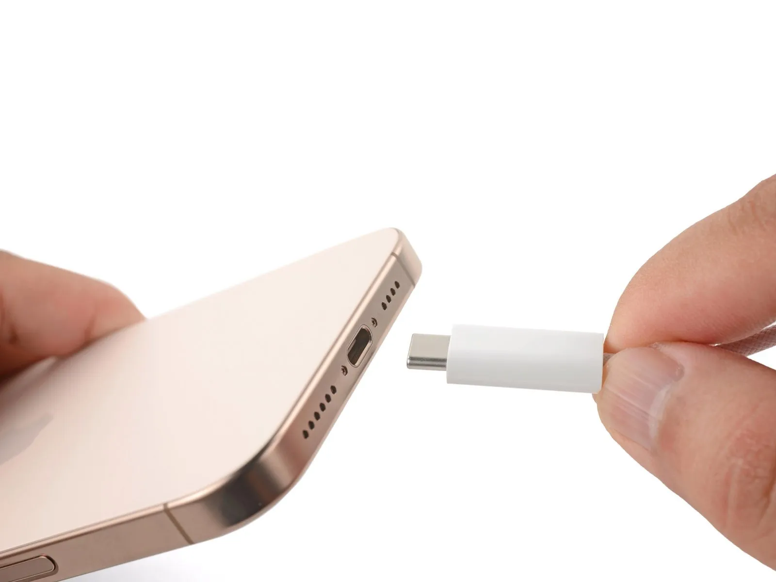
- Disconnect all connected cables from the iPhone prior to commencing the power-off procedure.
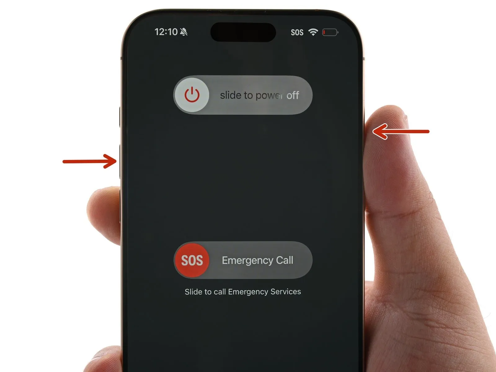
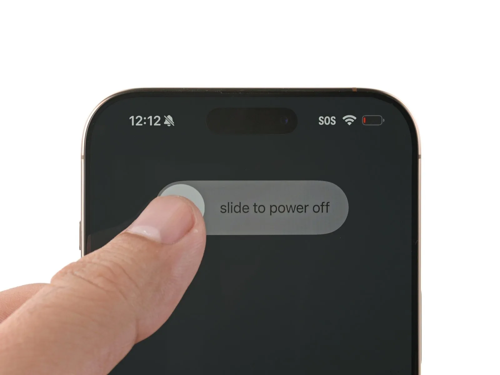
- Simultaneously depress the power button and either volume button, then utilize the swipe gesture to deactivate the iPhone.
Step 2 | Tape over any cracks
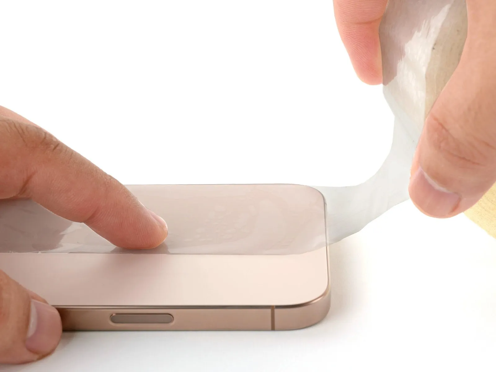
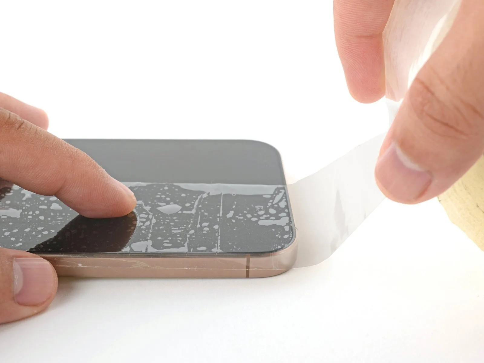
- To prevent injury and simplify the subsequent separation of components, apply several layers of adhesive packing tape across the fractured screen or rear glass surface.
- Ensure a sufficiently sized, uninterrupted section exists close to the lower perimeter, allowing for secure adhesion of a suction cup.
Step 3 | Remove the pentalobe screws
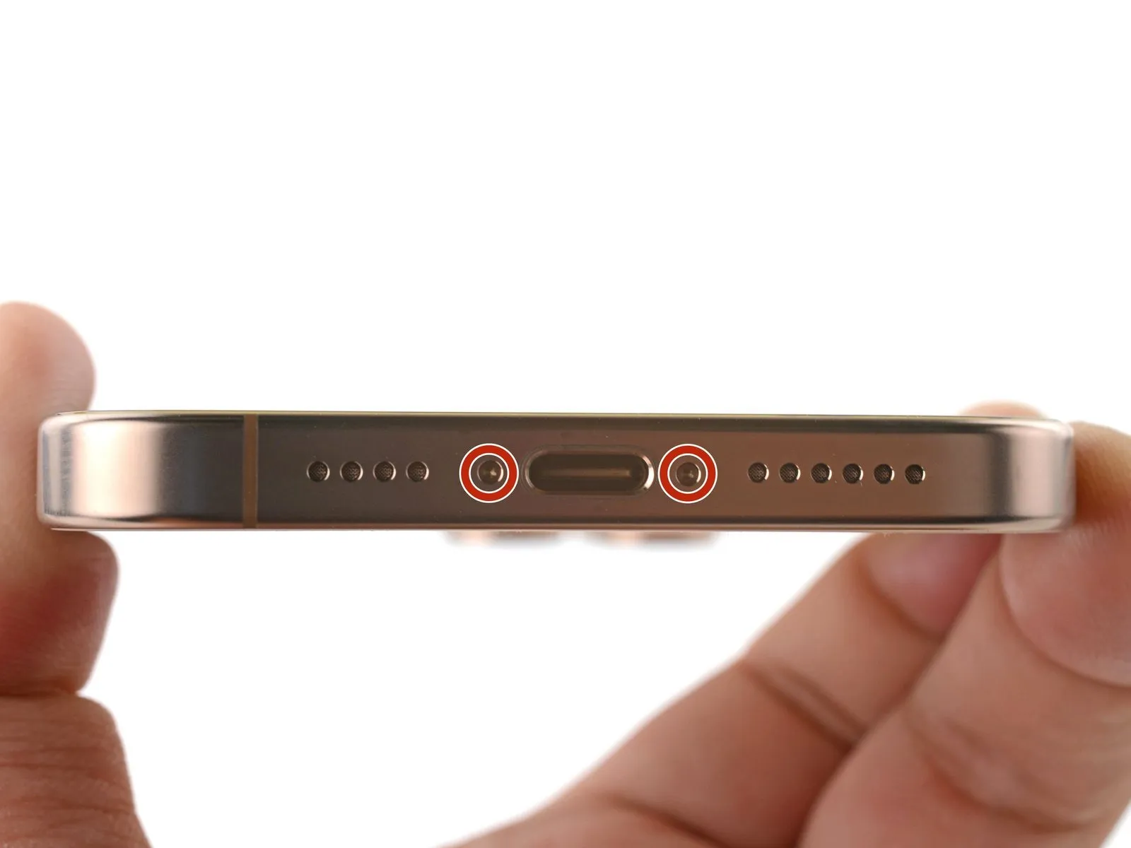

Employ a P2 pentalobe driver for the task of detaching the two screws, each measuring 7.4 mm in length, positioned laterally around the charging port.The two screws flanking the charge port must be unscrewed utilizing a P2 pentalobe driver.To facilitate removal of the screws situated on both sides of the charging port, a P2 pentalobe driver is required; these screws are each 7.4 mm long.
Step 4 | Mark your opening picks


- Caution is advised: Overly deep insertion of a prying tool poses a risk of device harm.To mitigate potential damage, implement the following procedure to indicate the safe insertion depth of your pick.
- Establish a reference point by measuring precisely 3 millimeters from the pick's distal end.
- Utilize a permanent marker to clearly denote this 3-millimeter position on the pick's tip.For enhanced precision, consider marking the pick's other corners with varying measurements to accommodate different opening scenarios.As an alternative method, affix a coin to the pick's tip, ensuring the coin's edge is positioned 3 millimeters from the pick's point.
- This marking serves as a visual guide, preventing the pick from being inserted beyond a safe distance.
- Adherence to this precaution will help avoid unintended internal component damage during the repair process.
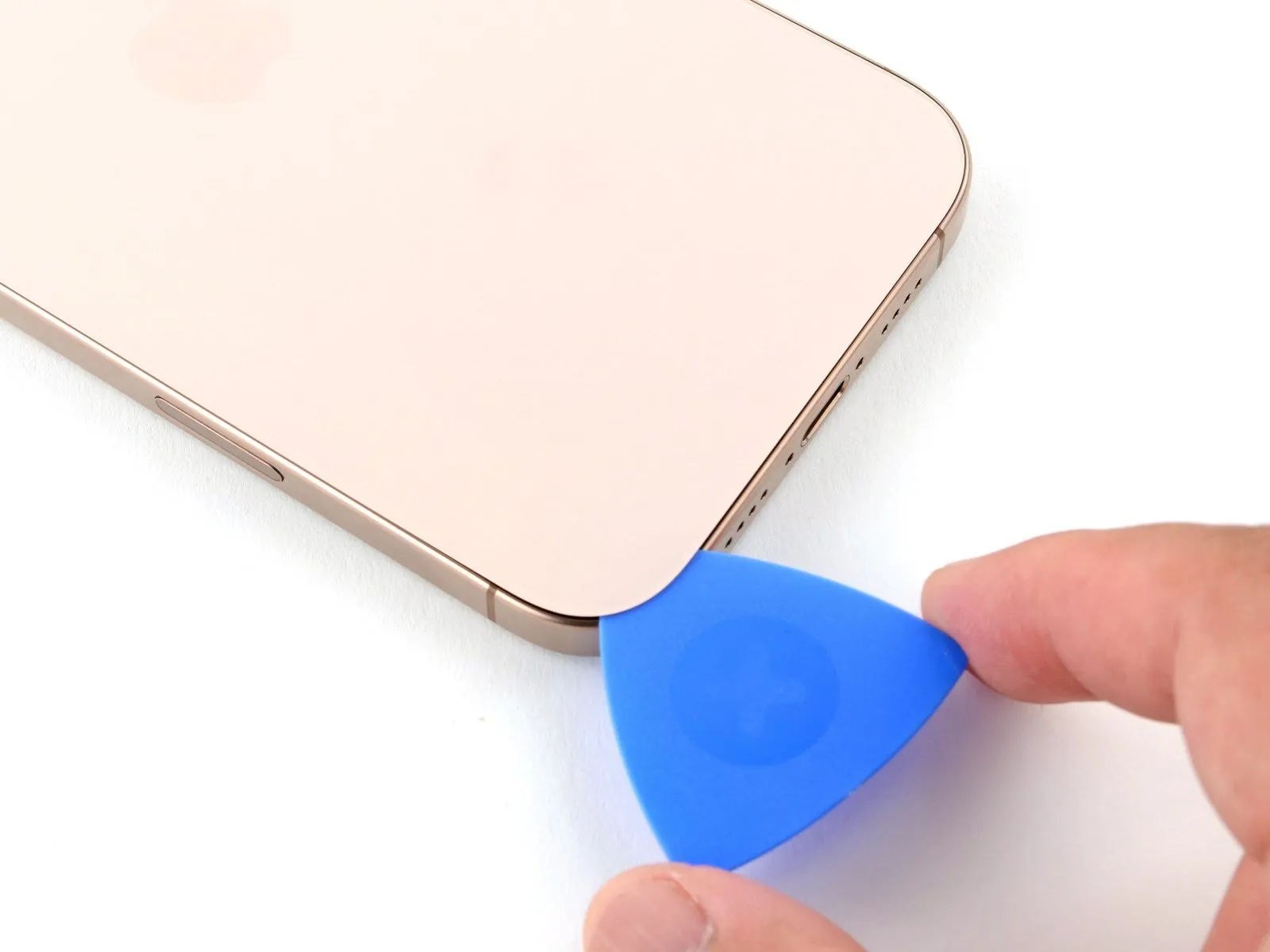
Step 5 | Create a gap using a suction handle
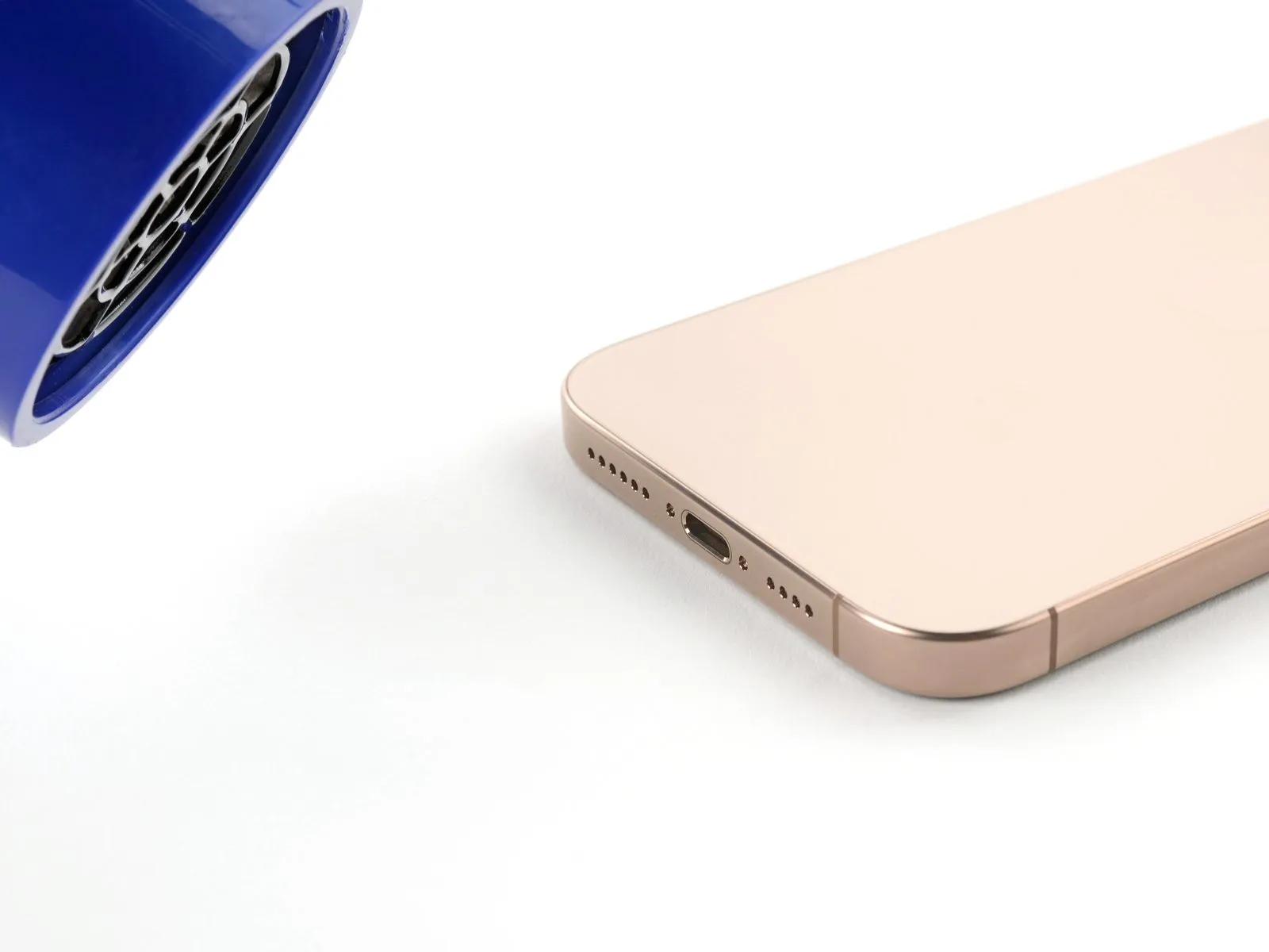
- The subsequent procedures detail the process of establishing a preliminary separation utilizing a suction handle.A hair dryer, or alternatively a heat gun, can be employed to warm the lower perimeter of the rear glass panel to a point where it registers as hot upon contact.An iOpener presents another viable option for applying heat to the rear glass surface.
- Adherence to the following guidelines is crucial for the correct application and heating of the iOpener.Employing a suction handle facilitates the creation of an initial space between components.To achieve the necessary temperature, direct heat from a hair dryer or heat gun towards the lower edge of the rear glass.The rear glass's lower edge requires heating until it becomes noticeably warm to the touch.An iOpener offers a specialized tool for localized heating and separation.
- Proper heating and application of the iOpener are essential for effective separation.The use of a hair dryer or heat gun allows for targeted warming of the rear glass.Ensure the bottom edge of the back glass reaches a temperature where it feels hot to the touch.Heating the rear glass with a hair dryer or heat gun prepares it for separation.The iOpener provides a method for applying heat and facilitating the initial gap.
Step 6


- Secure a suction handle to the lower perimeter of the rear glass panel.Exert a consistent, powerful upward pull on the handle to establish separation between the back glass and the device's frame.Should separation fail to occur, increase the localized heat application to the edge and attempt the process once more.
- Carefully introduce the pointed end of an opening pick into the newly formed space.
- The suction handle should be firmly affixed to the rear glass's lower boundary.
- A continuous, forceful upward motion on the handle is necessary to initiate a separation.Persistent lack of separation indicates a need for additional heat directed at the edge, followed by a renewed attempt.A specialized opening pick is required for insertion into the created void.
Step 7 | Back glass information
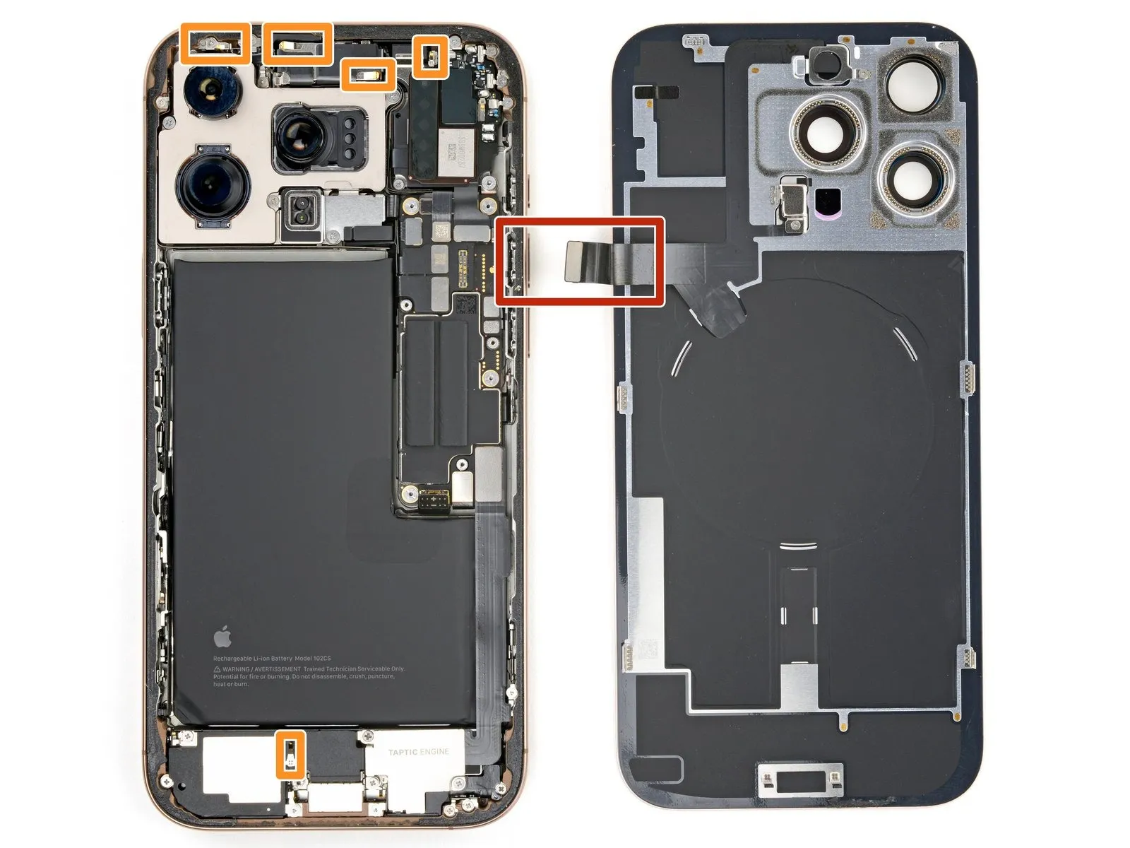
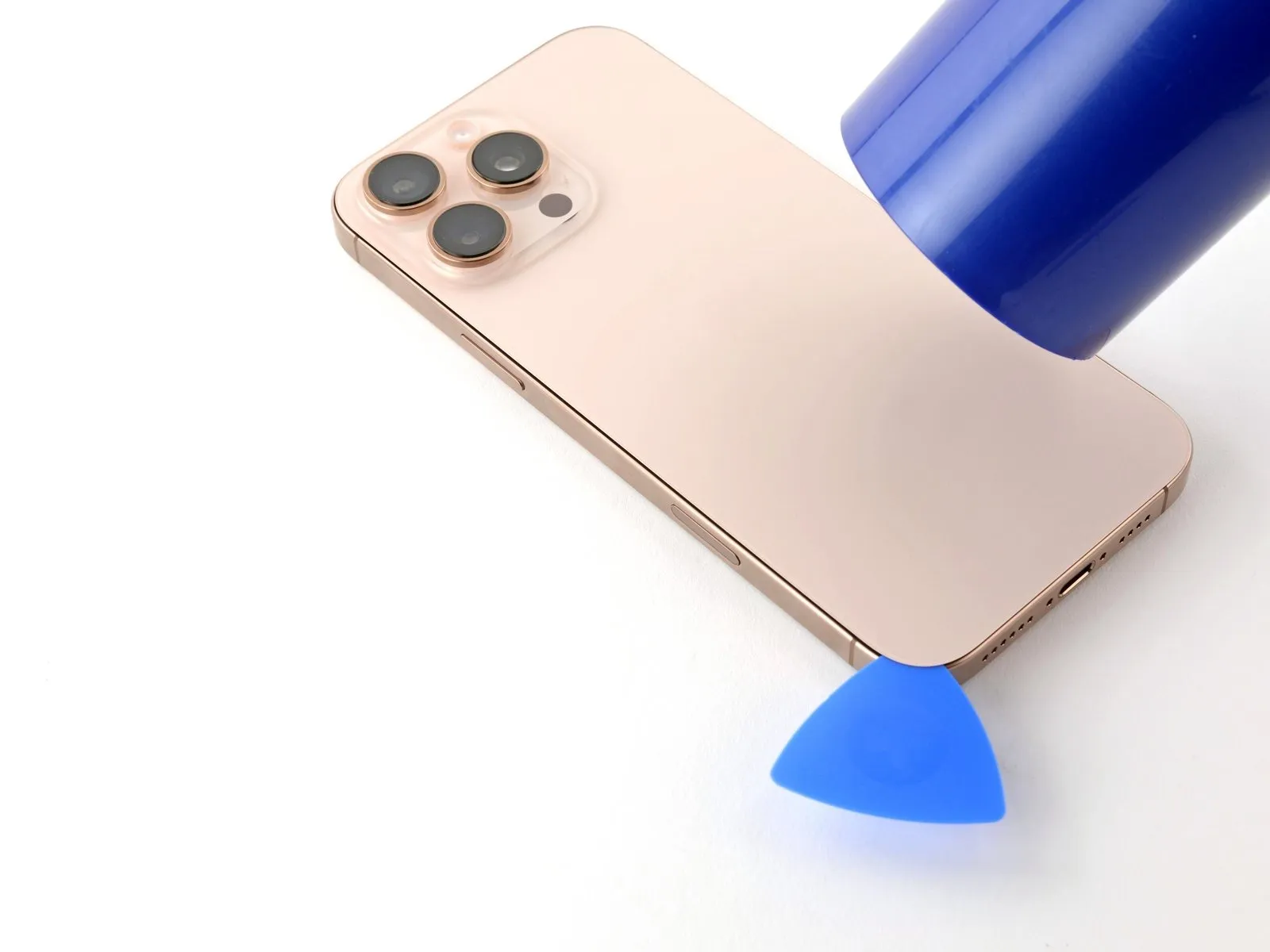
- During the process of separating the rear glass with a separating tool, maintain a maximum insertion depth of 3 millimeters to prevent potential harm to adjacent components.
- A fragile flex cable, situated near the volume up button and responsible for connecting the rear glass to the iPhone's internal circuitry, requires careful avoidance during separation to prevent cable damage.
- Numerous spring contacts are positioned along the iPhone's outer edges and must be protected from damage during the glass removal procedure.
Step 8 | Separate the bottom edge adhesive

- Utilize the opening pick, sliding it along the lower perimeter to sever the bonding agent.Should the adhesive present resistance during separation, apply heat for approximately one minute and attempt the process anew.Maintain the opening pick positioned within the lower-left corner to inhibit the adhesive from reattaching.
- The adhesive's separation can be facilitated by applying targeted heat.
- A minute of reheating can resolve difficulties encountered when slicing the adhesive.To maintain separation, secure the opening pick in the lower-left area.Employing the opening pick allows for a clean severance of the adhesive bond along the bottom edge.
Step 9 | Heat the left edge
Applying warmth with a hairdryer or heat gun to the left-hand side of the rear glass panel is necessary to facilitate separation.Elevate the temperature of the left edge of the back glass by using a heat source until it reaches a touch-sensitive warmth.The rear glass's left border requires thermal treatment via a hairdryer or heat gun to achieve sufficient warmth for disassembly.
Step 10 | Separate the left adhesive

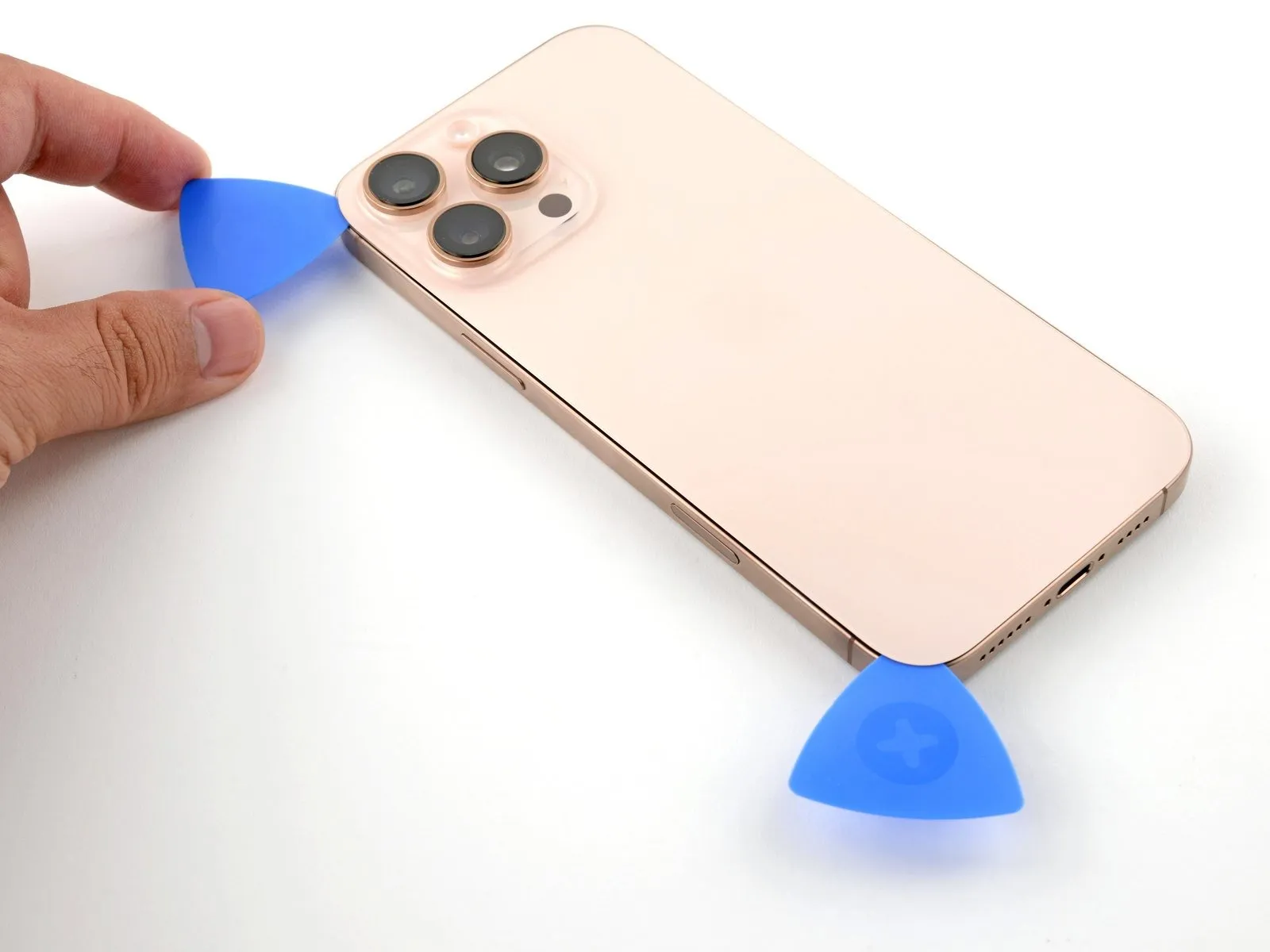
- Introduce a supplementary opening tool into the lower-left area, situated near the already placed tool.
- Ensure the tool's insertion depth remains below 3 mm to safeguard the spring contact points from harm.
- Move the tool along the left side to detach the adhesive bond and disengage the metal fasteners.
- The audible and tactile indication of metal clip release will occur as the tool traverses past them.
- Maintain the initial tool's position within the upper-left corner to inhibit the adhesive from re-adhering.
Step 11 | Heat the top edge and corner

Applying warmth with a hair dryer or heat gun to the upper edge and upper-right corner of the rear glass panel is necessary to soften the adhesive.The targeted areas should be heated until they reach a temperature that is perceptible upon contact.This warming process facilitates the separation of the back glass from the device's frame.
Step 12 | Separate the top adhesive

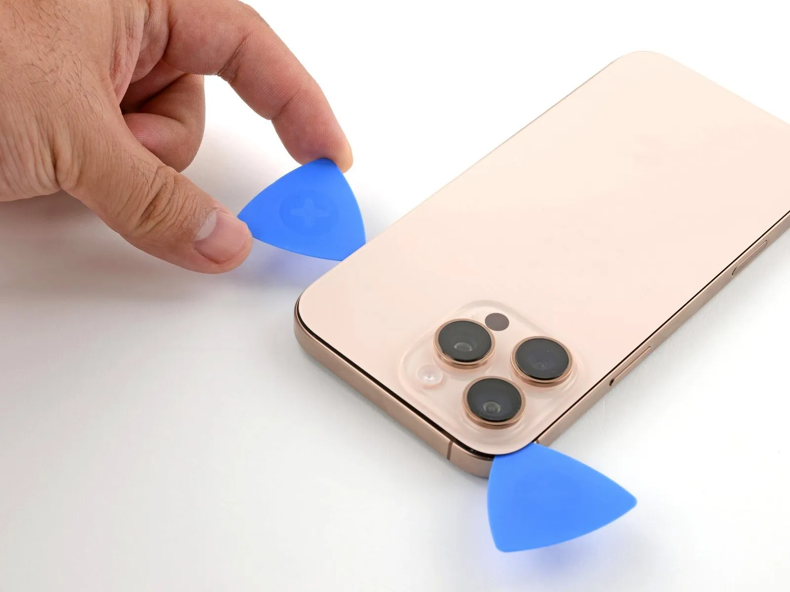
- To preclude harm to the spring contacts, ensure the insertion depth of your tool remains no greater than 3 millimeters.Employ a third opening tool and position it within the upper-leftmost recess.Advance the opening tool along the superior border, maneuvering it around the upper-right corner, and halt its progress directly over the volume up button.
- Maintain the placement of this tool to inhibit the adhesive from reforming a bond.
- Exceeding a depth of 3 mm risks compromising the integrity of the spring contacts.
- A third opening tool is needed to be introduced into the top-left corner.
Step 13 | Heat the right edge

Step 14 | Separate the right adhesive


- A fourth opening tool should be positioned within the lower-rightmost recess.
- Moving the opening tool along the corner and upward along the right side, pausing just beneath the volume down button, is required.
Step 15 | Reposition the back glass

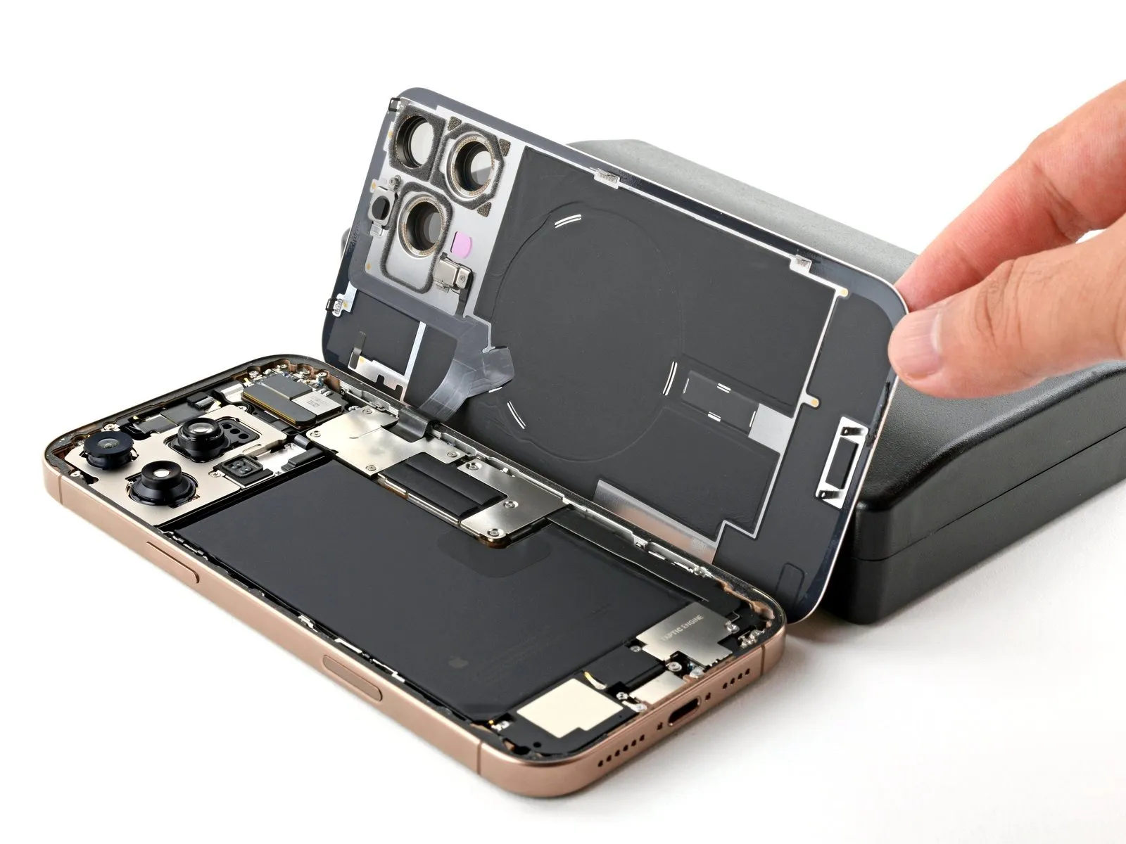
- Initiate the opening motion of the rear glass by pivoting it towards the right side of the iPhone, which will break the remaining adhesive bond.
Step 16 | Remove the battery connector cover

- Three screws, each measuring 1.3 millimeters in length, are utilized.
- A single screw with a 1.0-millimeter length is also present.
Step 17

Step 18 | Disconnect the battery
Step 19 | Remove the back glass connector cover

- A quantity of two screws are present.These screws measure 1.3 millimeters in length.Additionally, two screws are included.
- The length of these screws is 1.0 millimeters.Carefully observe the screw lengths to ensure correct reassembly.Properly matching screw sizes is crucial for maintaining device integrity.
Step 20
Step 21 | Remove the back glass
Step 22
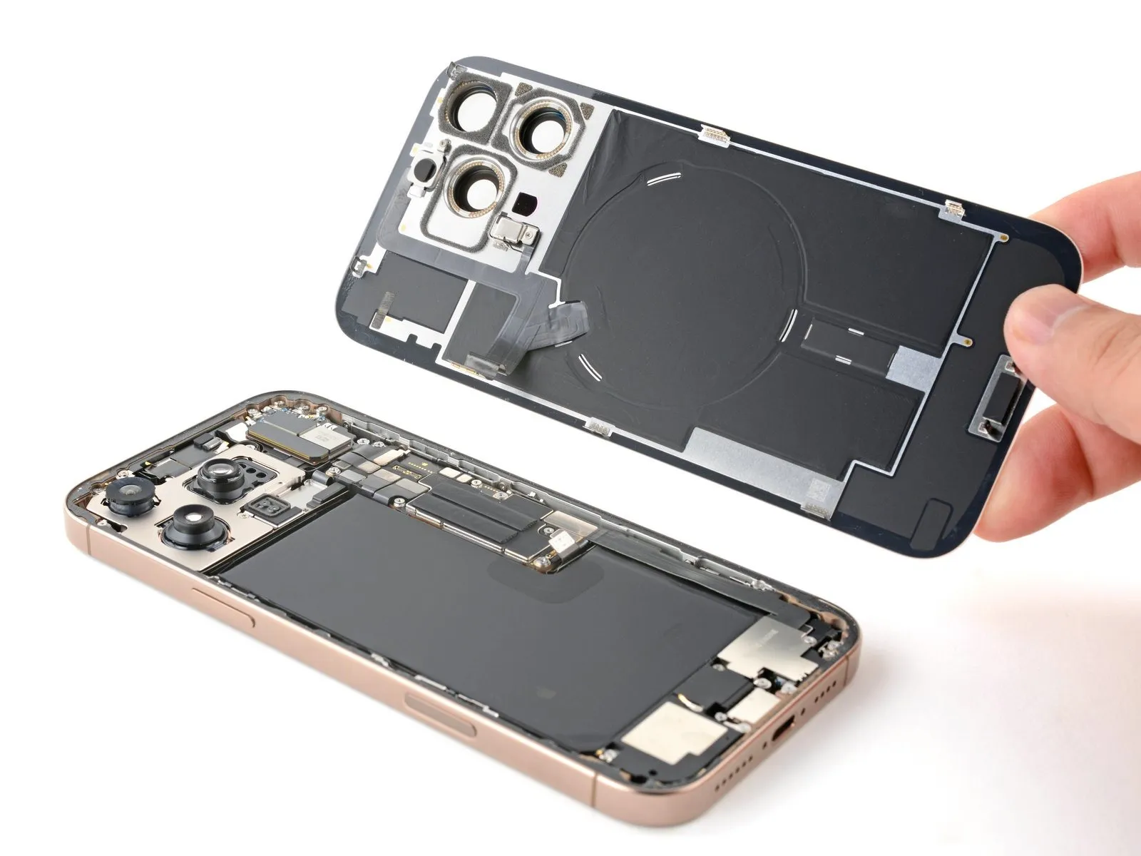
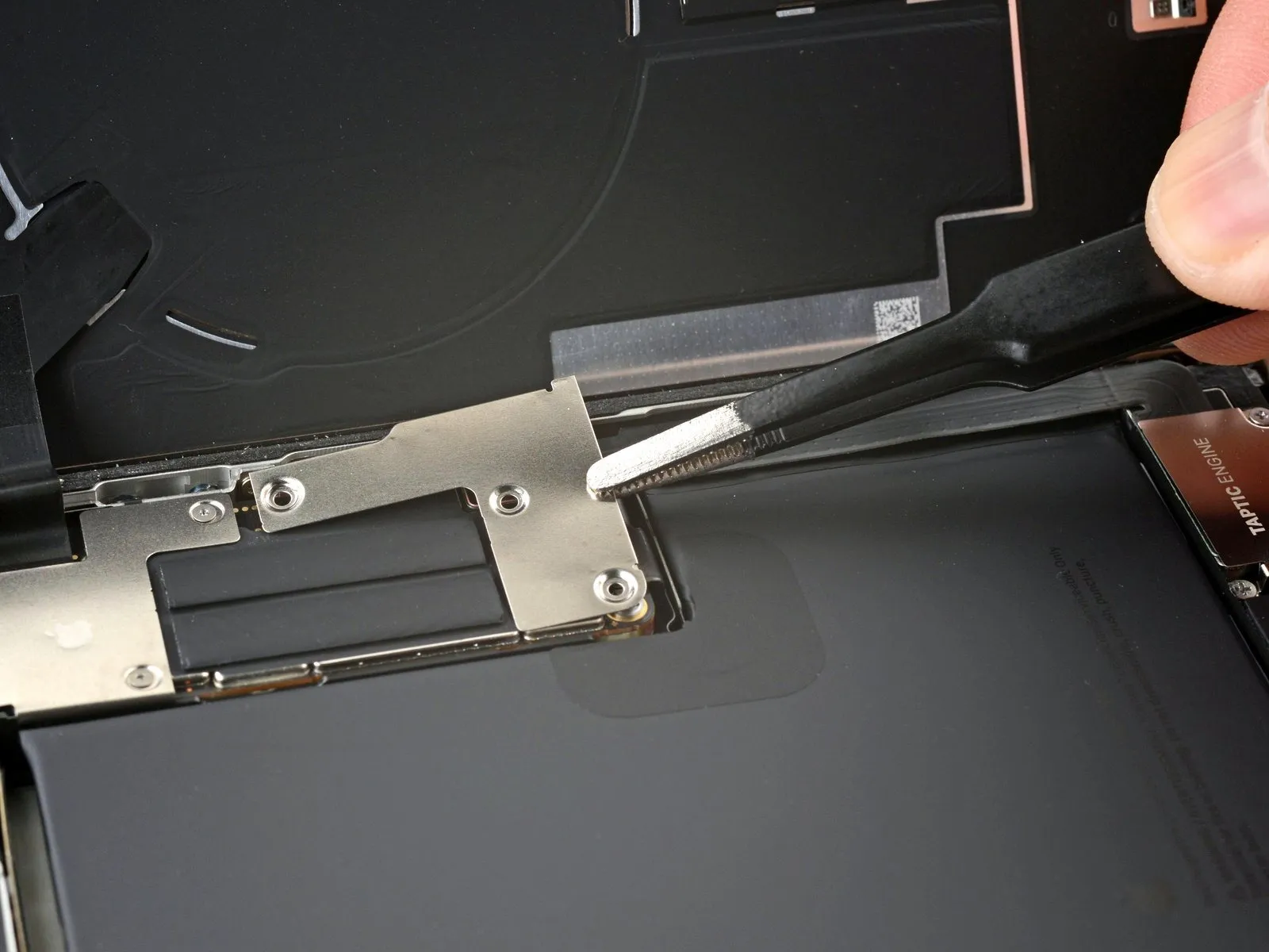
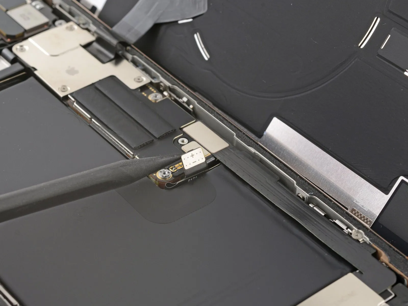
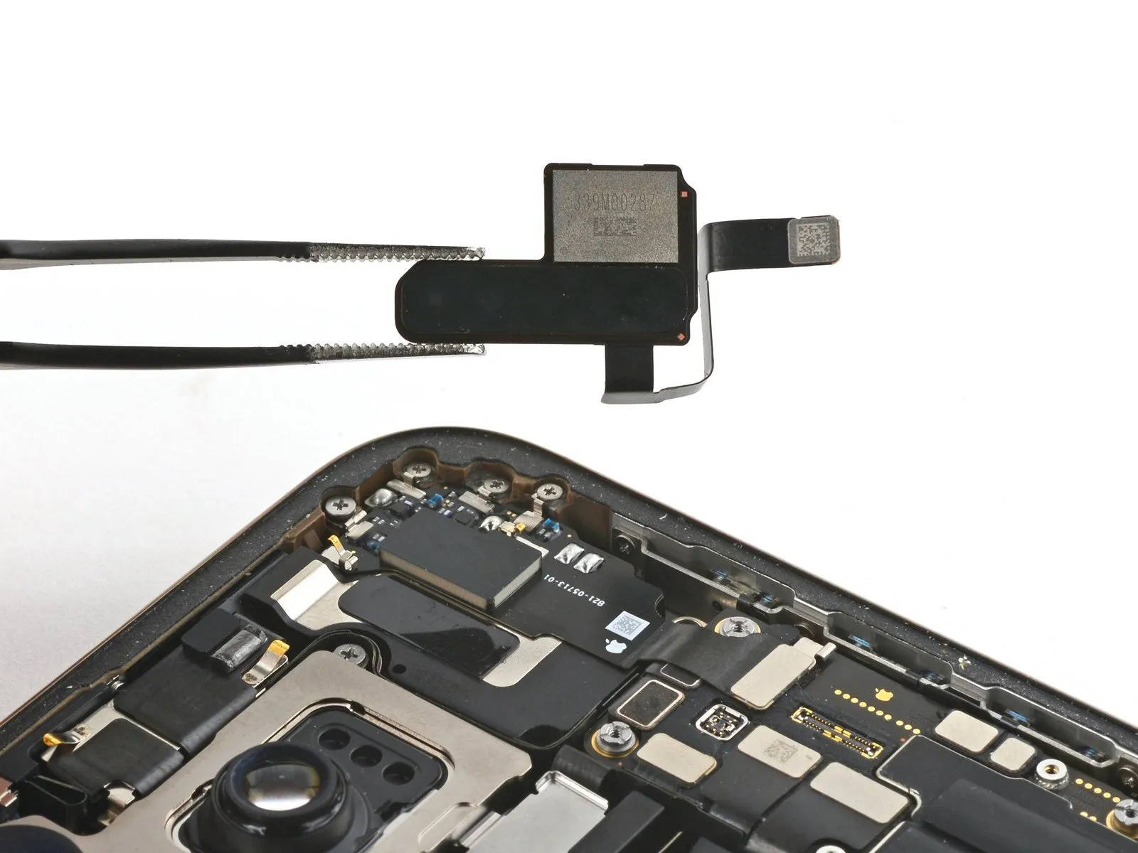
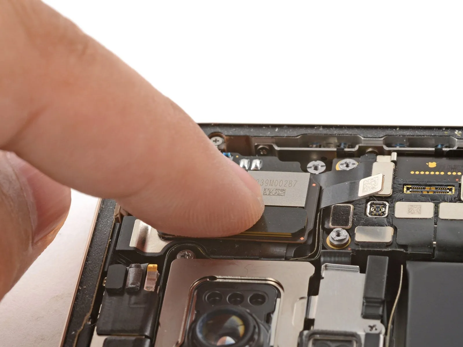
Step 23 | Remove the 5G mmWave antenna

Step 24
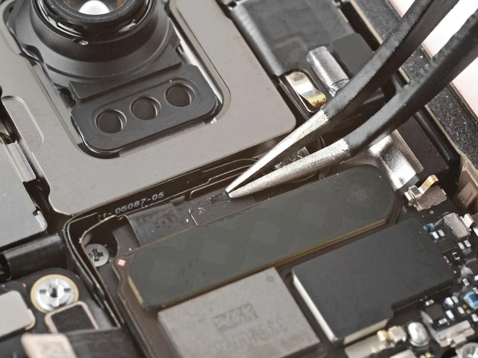

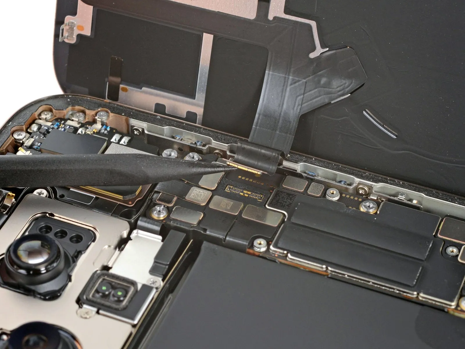
- A minimal quantity of stretch-release adhesive secures the 5G millimeter wave antenna's placement.
- Employ tweezers to gently lift the antenna's black adhesive release tab.
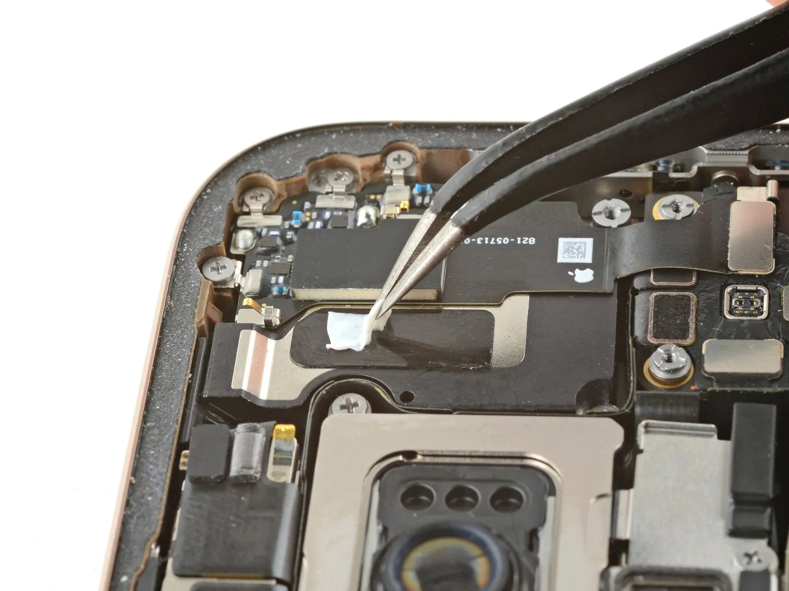
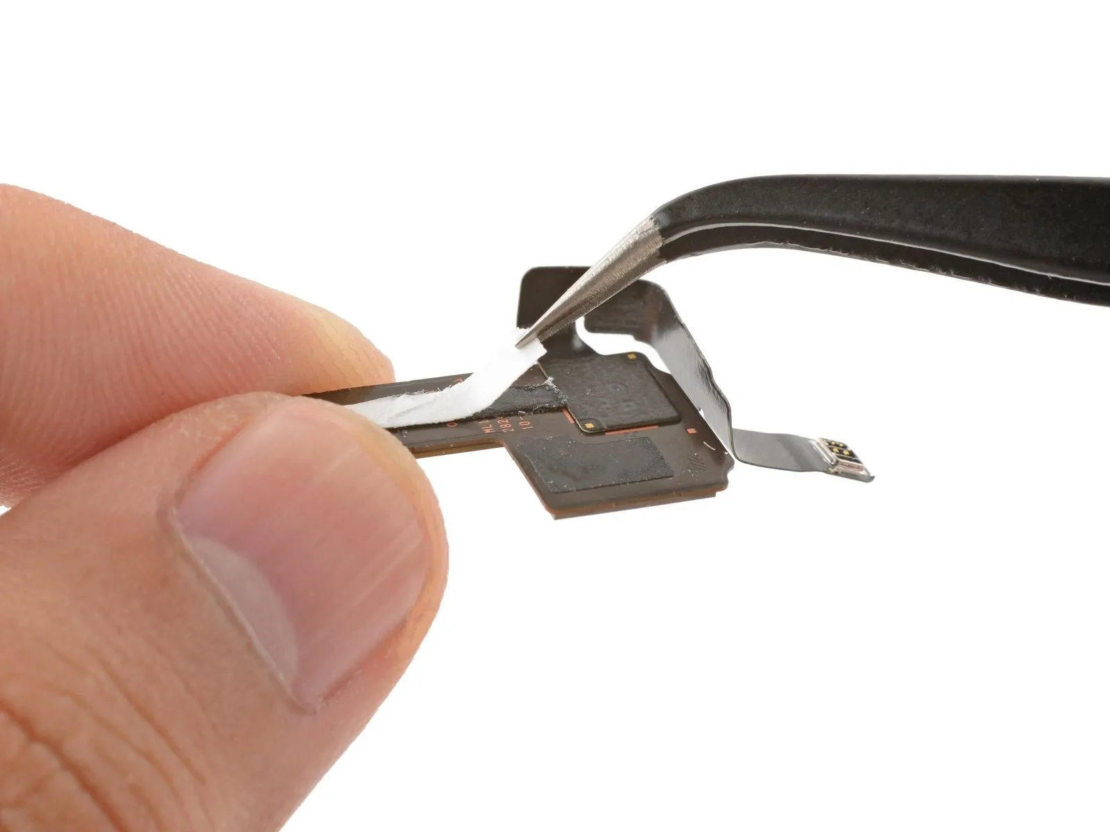
Step 25
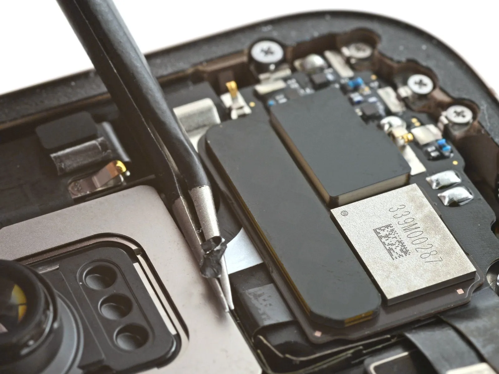
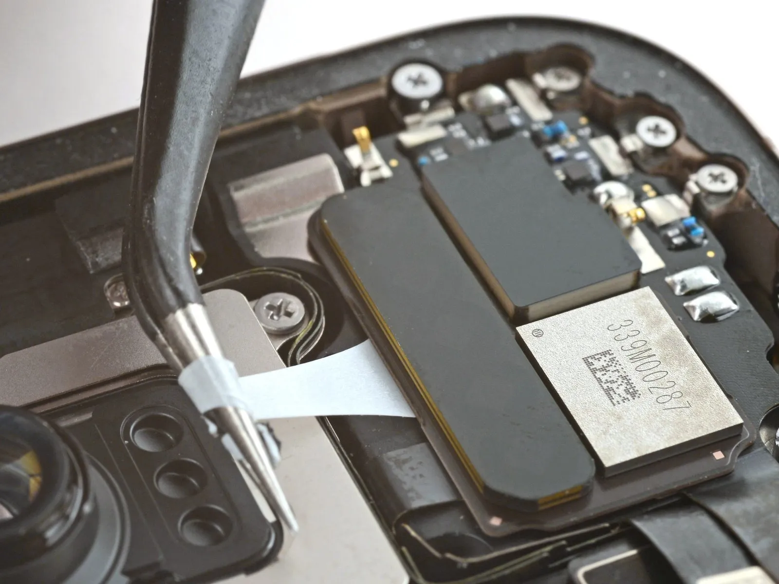
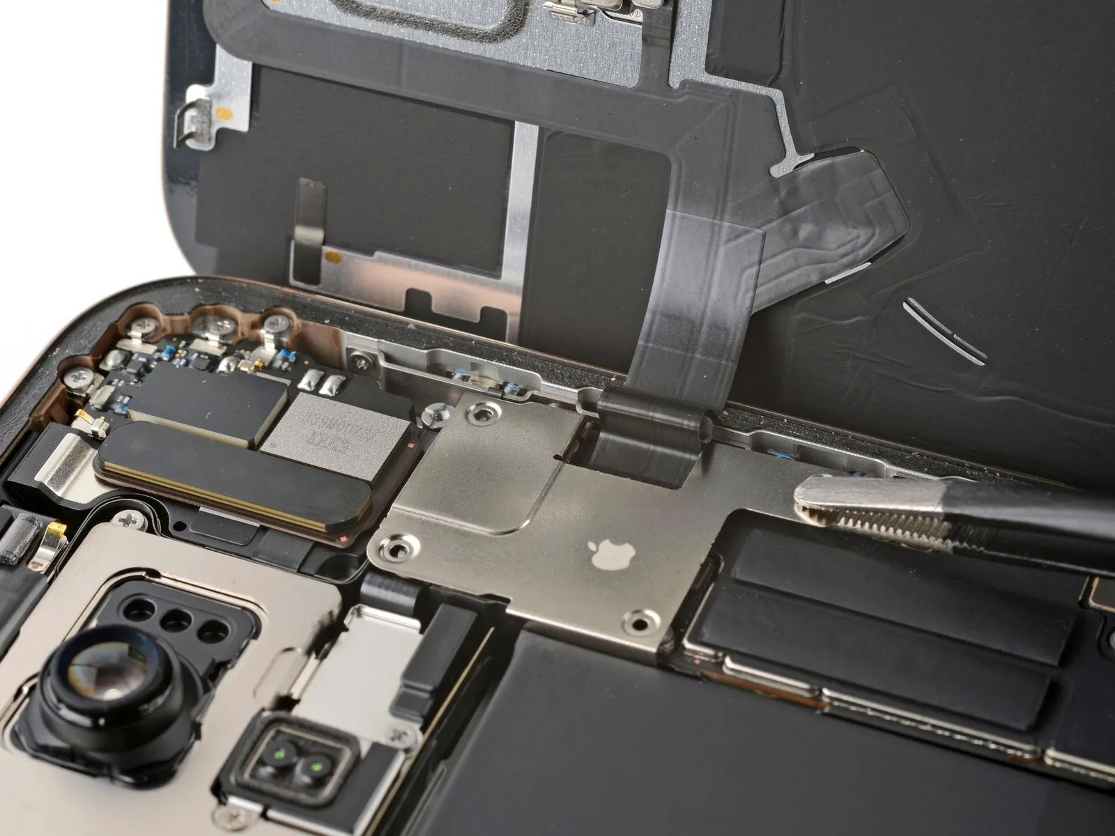
- Employing tweezers provides a secure grip on the adhesive pull tab, enabling a gentle, angled extraction.Should the adhesive fracture during removal, utilize tweezers to secure the detached portion and persist with the pulling action.When complete removal proves difficult, introduce a small amount of isopropyl alcohol exceeding 90% purity beneath the antenna to facilitate the subsequent procedure.
- A shallow angle is crucial when pulling the adhesive pull tab to prevent damage.The broken adhesive edge can be re-engaged with tweezers to maintain a firm hold for continued extraction.A single drop of high-concentration isopropyl alcohol, greater than 90%, assists in separating the adhesive from the surface.
- Successful extraction may require multiple attempts using tweezers to manage any breaks in the adhesive.
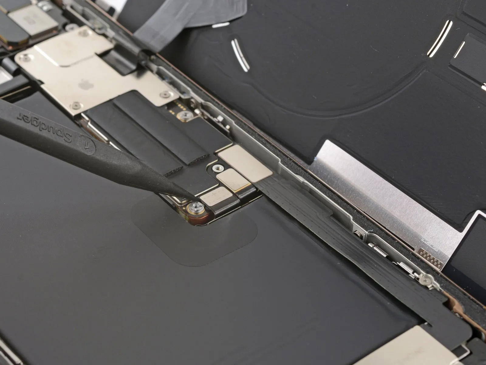
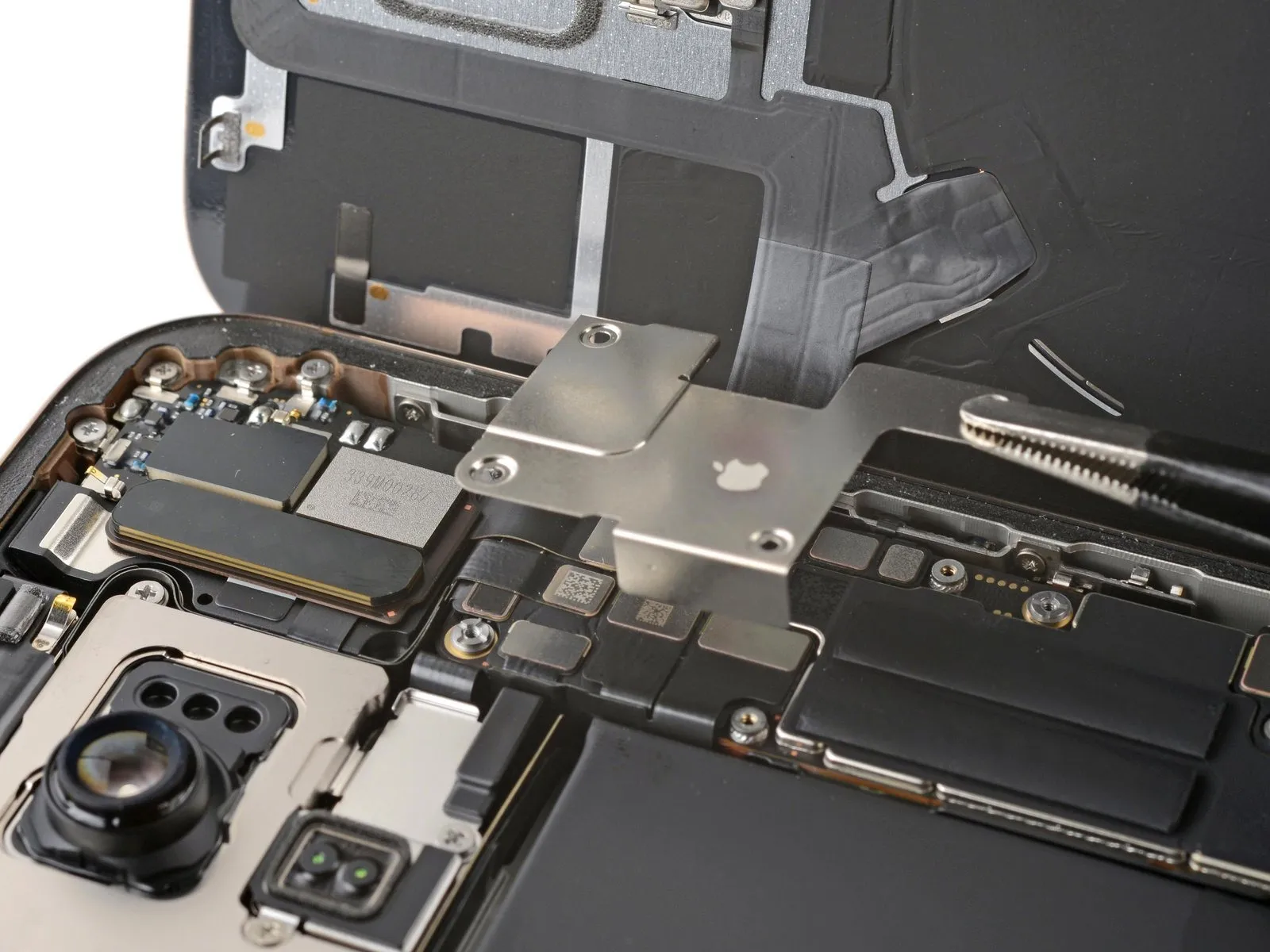
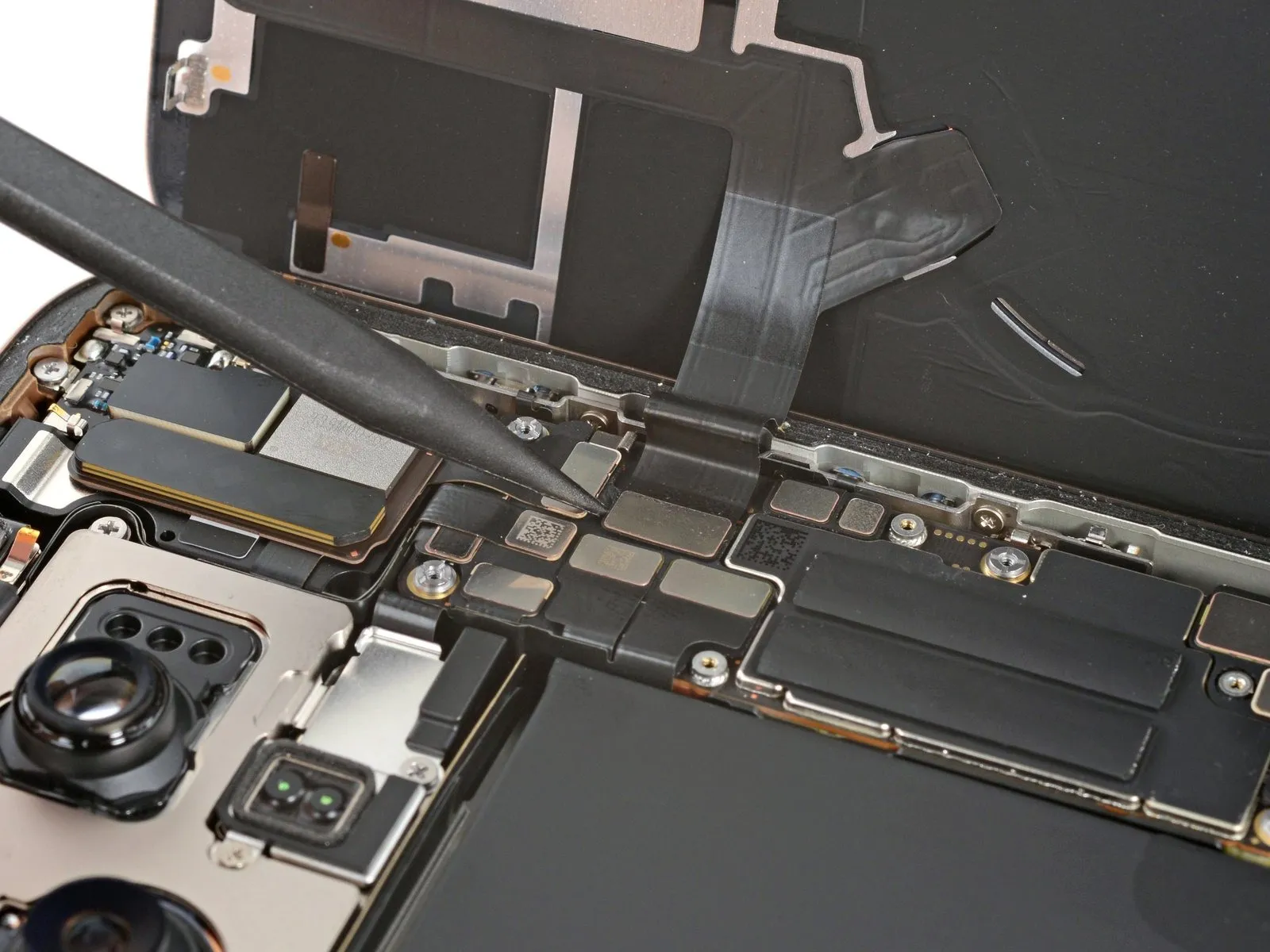
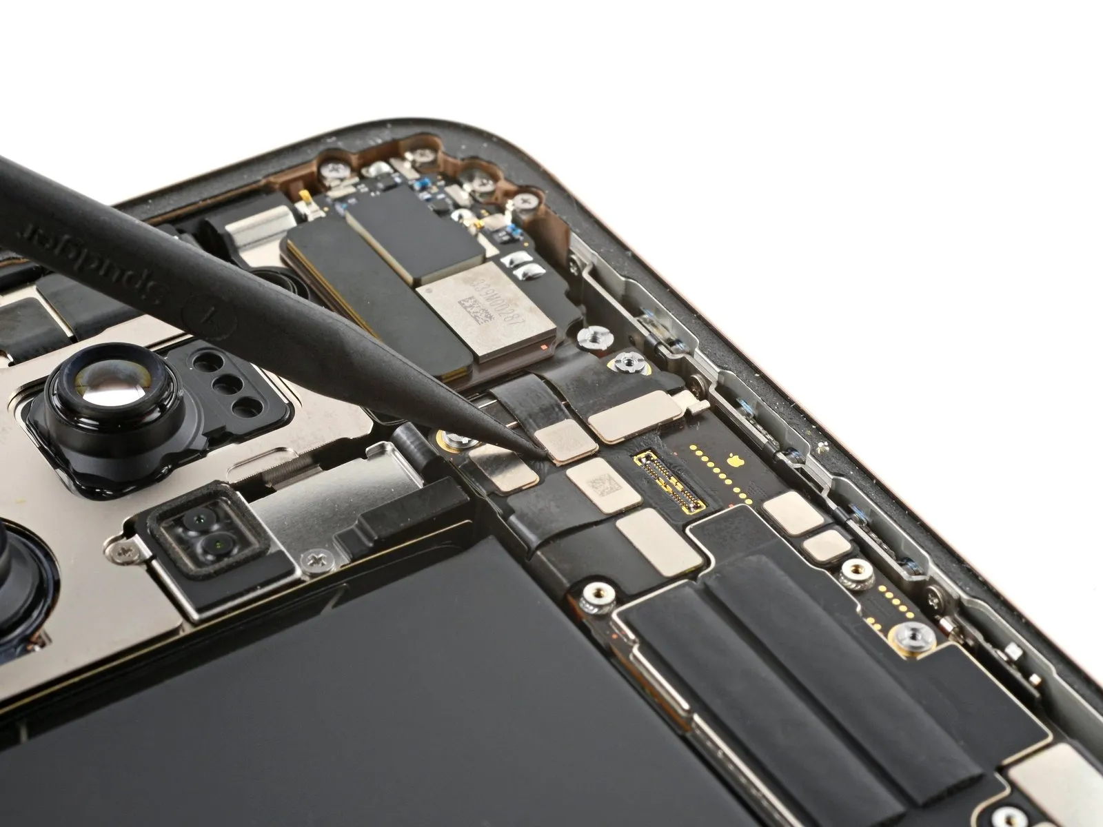
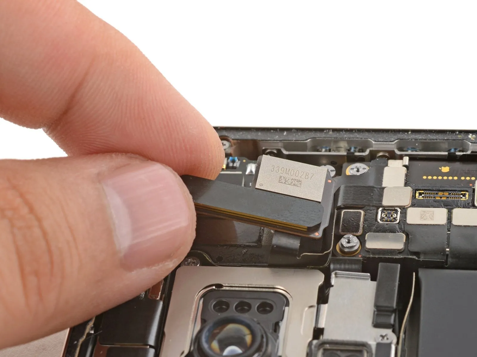
Step 26
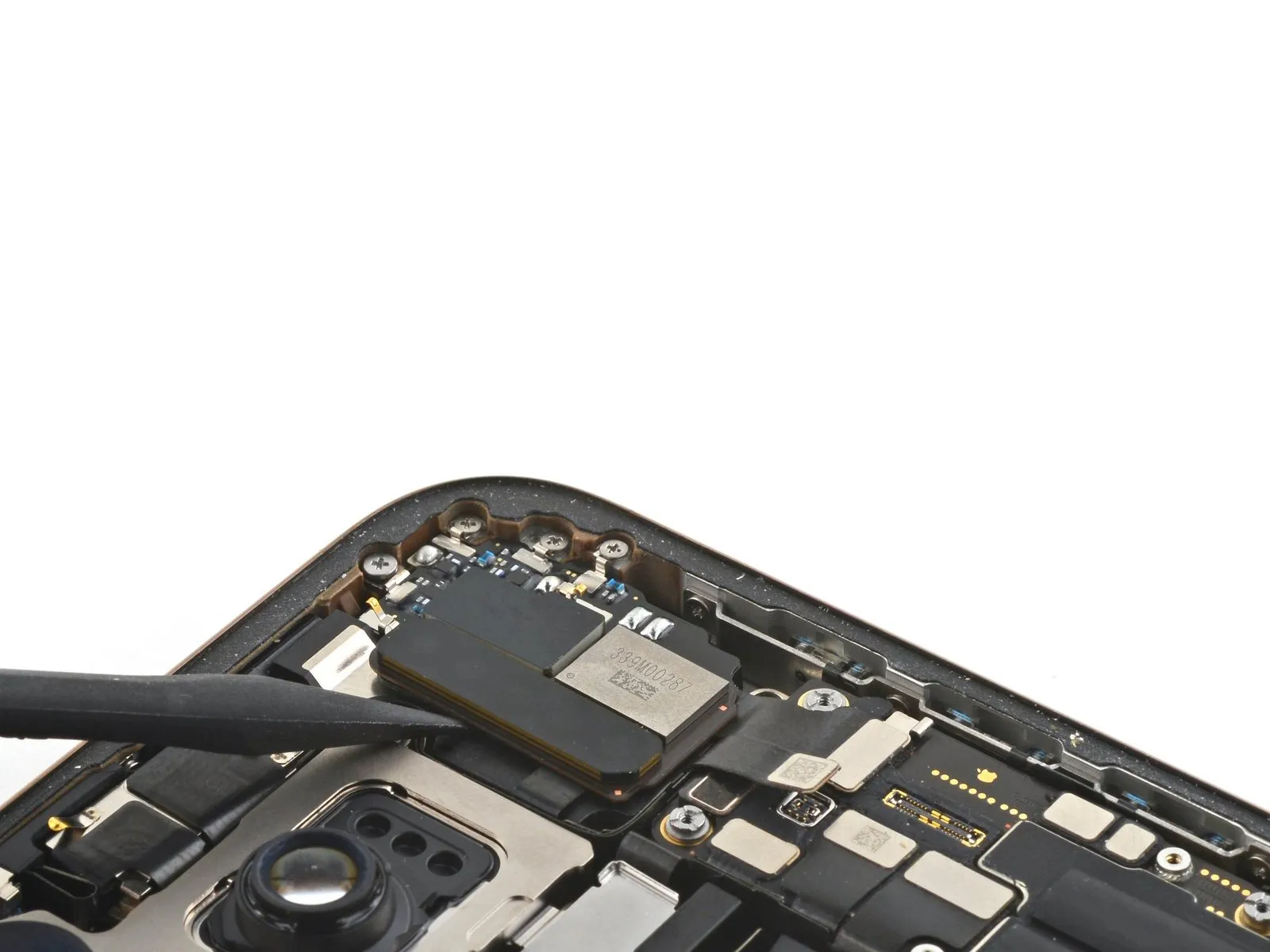

Employ the tip of a spudger to carefully lift and detach the 5G mmWave antenna.The antenna's secure attachment necessitates utilizing a spudger for controlled separation.To dislodge the 5G mmWave antenna, leverage the pointed end of a spudger for prying action.
Step 27 | Disassembly complete

Having finished the disassembly process, the subsequent instructions detail the reassembly procedure for your iPhone.
Slight variations in the visual appearance of reassembly images might occur based on the specific iPhone model being serviced; however, the documented steps remain accurate for all supported devices.
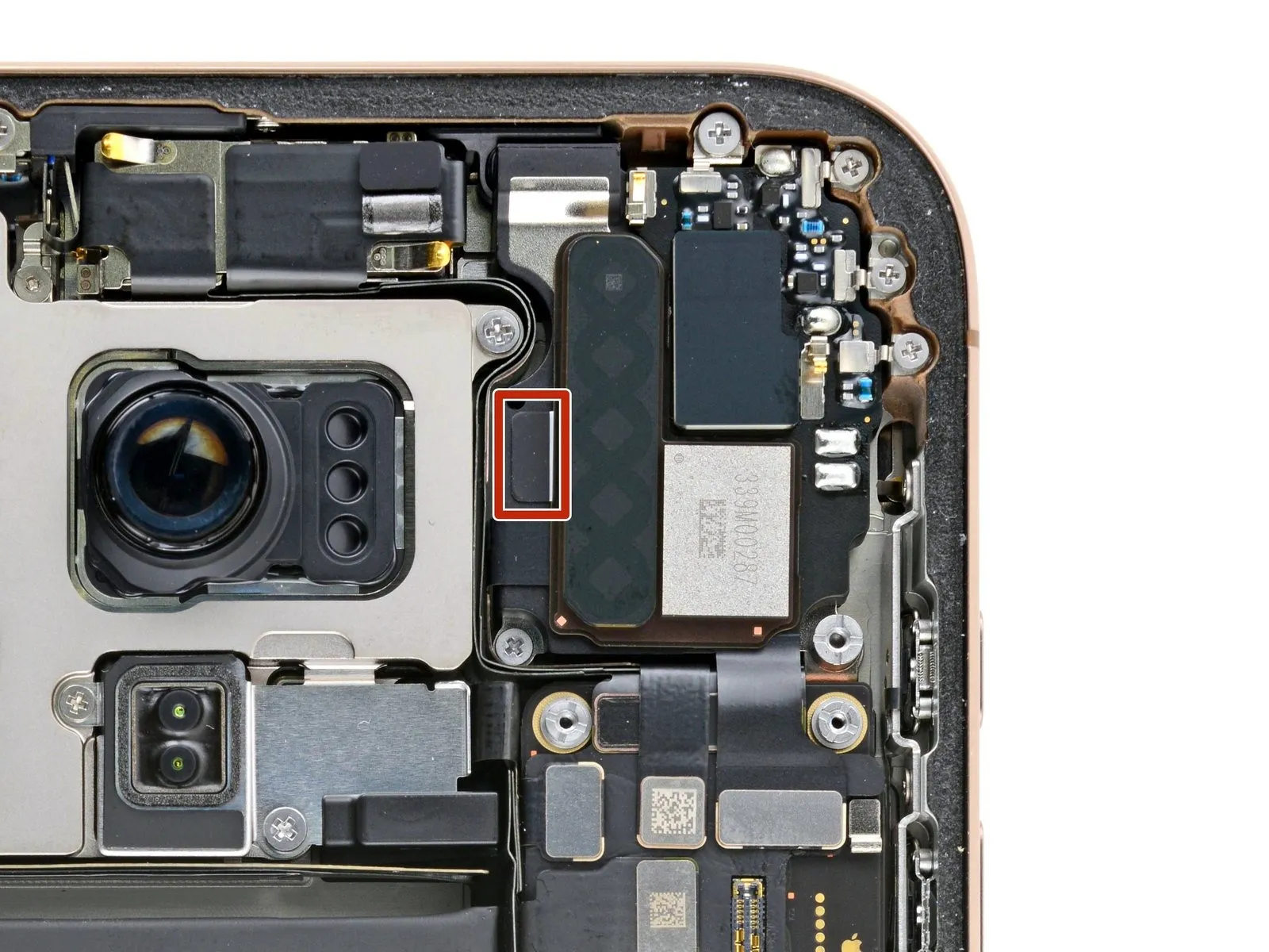
Step 28 | Install the mmWave antenna
- Employing either tweezers or a spudger, eliminate any leftover adhesive from the earpiece speaker's upper surface and the antenna's rear side.To ensure proper attachment, utilize a small segment of double-sided adhesive tape if the replacement component lacks pre-applied adhesive.Residual adhesive on both the earpiece speaker and antenna should be carefully removed with specialized tools.The antenna's securement to the earpiece speaker necessitates the removal of any existing adhesive traces.For parts lacking adhesive, a small piece of double-sided tape provides a reliable method of attachment.
- Employing a spudger or tweezers allows for the effective elimination of adhesive remnants from the designated areas.
Step 29
- Position the mmWave antenna precisely in relation to the earpiece speaker.Verify that the antenna's connector establishes contact with its corresponding socket on the logic board.Ensure the antenna's connector fully engages with the logic board socket.
- Apply pressure to the antenna against the earpiece speaker to establish a firm connection.
Step 30
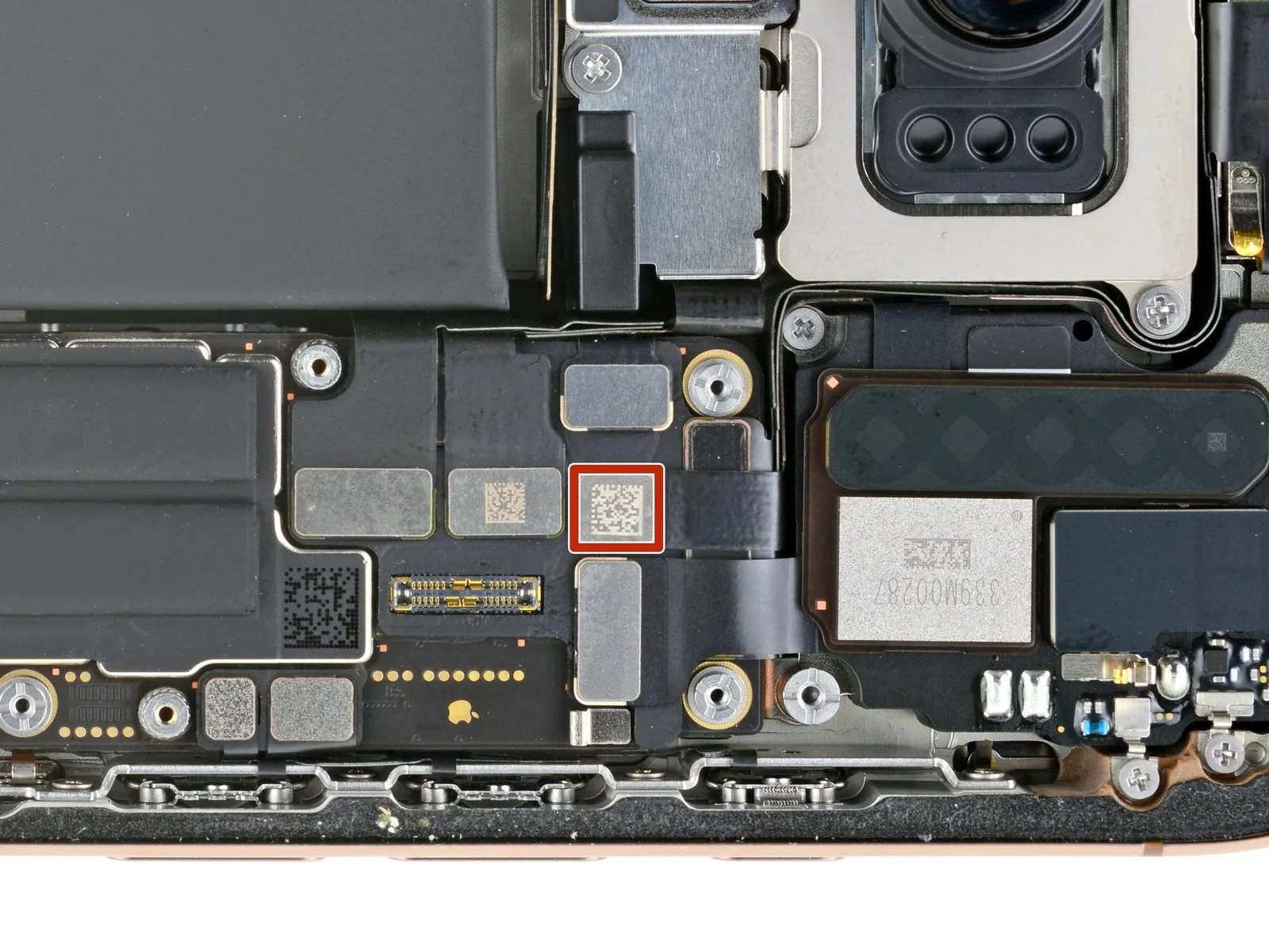
- Apply pressure to the antenna connector using a finger or a spudger to secure it to the logic board.For reconnection, meticulously align the connector and apply downward force to one edge until a distinct click is heard, then repeat the process on the opposing edge.Avoid applying pressure to the central portion of the connector during reattachment.
- Pin damage, potentially irreversible, can occur if the connector's alignment is incorrect.
- Proper alignment is crucial to prevent bending of the connector's pins, which could result in permanent component failure.
Step 31 | Remove the leftover adhesive


Should a grounding clip become displaced, carefully restore it to its original position utilizing your fingers or a pair of tweezers.
Employ blunt-nose tweezers or your fingers to detach sizable adhesive fragments from the frame's edges.
Employing a spudger, meticulously remove any remaining adhesive residue adhered to the frame's surface.
For particularly resistant adhesive, apply warmth with a hairdryer or heat gun to soften it, then attempt removal again.
Step 32 | Clean the back glass


To facilitate proper adhesion, employ a microfiber or lint-free cloth saturated with a few drops of isopropyl alcohol with a purity greater than 90 percent to clean the perimeter of the back glass if it is being reused.
Step 33 | Clean the frame

- Cover the tip of a spudger with a non-abrasive cloth, such as a lint-free cloth or coffee filter, before applying a small amount of isopropyl alcohol with a concentration exceeding 90%.The spudger's tip, now moistened with alcohol, should be used to carefully clean the frame's edge, moving in a single direction to remove adhesive remnants.Careful attention to detail is essential during this cleaning process.
- A thoroughly cleaned frame is critical for the proper application of replacement adhesive.
- Ensuring an even adhesive layer requires meticulous cleaning, which contributes to a stronger and more reliable bond.
Step 34 | Apply the replacement adhesive

- Position the adhesive sheet onto the frame's surface to establish the correct alignment.
- Employ elements like the camera aperture and indentations on the upper and lower borders to confirm the adhesive's placement within the frame.
Step 35


- Grasp the corner tab of the adhesive backing and carefully remove a portion of the liner, revealing approximately one-third of the adhesive surface.The adhesive material possesses a high degree of tackiness; prevent unintended contact with other surfaces until application to the frame is prepared.Should your adhesive sheet incorporate multiple layers of liner, remove only the layer that exposes the surface intended for bonding to the frame.
- The exposed adhesive's strong adhesion requires careful handling to avoid premature bonding.
- Prior to application, ensure the adhesive remains free from contaminants to guarantee proper adhesion to the frame.
Step 36


- Ensure precise positioning of the visible border on the adhesive striprelative to the matching edge found on the iPhone's chassis.
- Because adhesive placement is permanent, any misalignment necessitates removal and replacement with a fresh strip.
- Following proper alignment, apply gentle pressure to secure the adhesive stripto the frame.
Step 37


- Carefully remove the adhesive backing, ensuring firm contact between the adhesive and the surface.
- Proper alignment of the adhesive is indicated by a seamless fit of the edges with the surrounding frame.
- To correct minor misalignments, delicately reposition the longer sides of the adhesive towards the frame.
- Should the adhesive develop creases or wrinkles, discard it and apply a new set for optimal results.
- In the absence of replacement adhesive strips, the iPhone can be reassembled and used temporarily; however, be aware that water resistance will be reduced until a new adhesive is installed.
Step 38


- Employ a spudger to apply pressure to the adhesive securing the iPhone's edges.
- Exercise caution near the delicate grounding clips; should one become displaced, carefully restore it to its original position utilizing your fingers or tweezers.
- Avoid excessive force, as this could cause the adhesive to become distorted and lose its intended shape.
Step 39


- Employ a spudger or manual dexterity to disengage the pull tab affixed to the extensive front liner, typically located within a corner.
- Utilize the pull tab to detach the expansive front liner from its adhesive backing.
- Remaining liners may still protect the outer edges, safeguarding the adhesive surface during reassembly; postpone their removal for the time being.
Step 40 | Connect the back glass

To facilitate access, carefully support the rear glass component by applying pressure along its right-hand border on the iPhone.
Step 41

To establish a secure connection between the rear glass connector and the logic board, apply pressure using either a fingertip or the broad, planar edge of a spudger tool.Ensure proper alignment before applying force to avoid damaging the delicate components on the logic board.The rear glass connector must be firmly seated on the logic board to maintain functionality.
Step 42 | Connect the battery

- Apply pressure to secure the battery press connector to the logic board, utilizing either a fingertip or a spudger tool.Before finalizing the iPhone's reassembly, it's advisable to verify the repair's functionality; initiate the device and confirm expected operation, then deactivate it to proceed.Should the iPhone fail to power on, establish a connection to an external power source and attempt activation once more.
- In the event that a logic board replacement occurs and the display remains unresponsive, consult the dedicated screen repair guide to perform a manual connection of the display connector.
- Ensure the battery press connector is firmly engaged with the logic board by applying consistent pressure with a finger or a spudger.
- To confirm the repair's success prior to final assembly, activate the iPhone and verify all functions operate normally, then deactivate the device for continued reassembly.
Step 43 | Install the connector covers

Position the back glass connector cover so that the screw apertures are aligned, then set it down.
Step 44
Employ a specialized tri-point Y000 driver for the task of fastening the back glass connector cover.The cover is held in place by four screws requiring a tri-point Y000 driver for removal and installation.Two screws, each measuring 1.3 millimeters in length, are part of the fastening assembly.
- The securing mechanism includes two screws with a length of 1.0 millimeters.Secure the back glass connector cover utilizing a tri-point Y000 driver to engage the screws.
- A tri-point Y000 driver is essential for manipulating the screws that retain the back glass connector cover.The four screws fastening the back glass connector cover necessitate the use of a tri-point Y000 driver for proper installation.
Step 45

Position the battery connector cover so that the screw apertures are aligned, then set it down into its designated location.
Step 46
- Employ a tri-point Y000 driver for the battery connector cover's screw installation.The cover is fastened with three screws requiring a tri-point Y000 driver for removal and installation.Two screws, each measuring 1.3 millimeters in length, are used to secure the battery connector cover.
A single screw, with a length of 1.0 millimeters, is also part of the battery connector cover's fastening mechanism.To properly engage the screw heads, a tri-point Y000 driver is essential.
The battery connector cover is held in place by a combination of two 1.3 mm screws and one 1.0 mm screw.Ensure the correct driver, a tri-point Y000, is utilized to avoid damaging the screw heads during the installation process.
Step 47 | Remove the final adhesive liners


- Employing either your fingertips or a spudger, carefully separate the surrounding liner layers to reveal the underlying adhesive.
During liner removal, prevent any contact between surfaces and the newly exposed adhesive to maintain its bonding properties.
Thoroughly inspect both the frame and rear glass assembly, eliminating any residual liner fragments to guarantee complete adhesive exposure.
Step 48 | Install the back glass


- Position the rear glass component onto the device frame, initiating the placement with the uppermost boundary.
Should you encounter opposition during installation, a surrounding retaining clip might be deformed and compressed by the frame; carefully examine the area of resistance and delicately realign any clips that are not straight.
Apply even pressure across the iPhone's borders to ensure the rear glass makes complete contact with the frame.
Step 49 | Apply heat to the perimeter

- Employ a hair dryer, heat gun, or iOpener to warm the edges of the rear glass.Continue applying heat until the surface temperature becomes uncomfortable to briefly touch.This warming process reduces the adhesive's viscosity.The softening action facilitates a more secure re-bonding later.Ensure the device's perimeter is uniformly heated to prevent uneven adhesive release.Avoid overheating a single area, as this could damage the display or other internal components.The goal is to make the adhesive pliable, not to melt any parts.
Careful temperature management is crucial for a successful repair.
Step 50 | Apply pressure to the perimeter


- Employ your fingertips to apply consistent, secure pressure encompassing the entire outer edge of the iPhone's casing.
Step 51


- Position the iPhone with its display facing downwards onto a pristine, level workspace.
Apply a continuous strip of adhesive tape along the outer edge of the rear glass to safeguard its cosmetic appearance.
Arrange a circular stack of coins along the edge of the rear glass, constructing a barrier that matches the height of the rear camera lenses' projections.
As an alternative method, secure the device with vise clamps around its outer edges to properly establish the fresh adhesive seal.
Step 52


- To apply even pressure, position four to five substantial books flatly atop the iPhone’s surface.
Because the weight could potentially create minor marks on the book covers, avoid using books of significant monetary value.
Maintain the books’ position for approximately half an hour to ensure adequate contact time.
This sustained force facilitates the bonding process of the adhesive material.
Step 53 | Install the pentalobe screws
Utilize a P2 pentalobe driver for screw manipulation.The two screws, each measuring 7.4 millimeters in length, require installation.These fasteners are positioned laterally, flanking the charging port.Properly securing these components necessitates the use of the specified driver.