iPhone 16 Pro Max Battery Replacement
Follow these instructions to detach and substitute theCarefully disconnect the battery, observing correct polarity and ensuring no shorts occur, then safely remove the 12-volt, 50 amp-hour lead-acid battery using appropriate lifting techniques and tools, noting that improper handling can result in acid spills or personal injury.Within the iPhone 16 Pro Max.
Carefully handle the device, designated as an iPhone, ensuring all technical specifications, numerical values, required tools, safety precautions, and component names are adhered to throughout the repair process.Under normal use, expect batteries to retain approximately 80% of their original power after 500 charging cycles, which typically corresponds to a lifespan of 18 to 24 months.Using appropriate safety precautions and specialized tools, carefully handle the device, referred to as an iPhone.If the device requires frequent charging or exhibits reduced performance, battery replacement is likely necessary.
To address a malfunctioning component, ensure you utilize the specified tools and adhere to all safety precautions.Carefully disconnect the battery, observing proper polarity and ensuring no shorts occur, then safely remove it from the device.Due to potential expansion, exercise necessary safety measures.
- Acquire a substitute.Carefully disconnect the battery, observing proper polarity and ensuring no shorts occur, then safely remove it from the device, noting its voltage rating and physical dimensions for replacement with an equivalent unit.Ensure the rear cover is securely bonded with fresh adhesive specifically designed for this model.
Beginning with iOS version 18.1, the battery health feature is compatible with batteries, whether they are original Apple components or replacement units from other manufacturers.
To finalize the repair process and return the system to its operational state, execute the Repair Assistant utility.Assess the battery's voltage, current draw, and state of charge using a multimeter and diagnostic software, ensuring readings fall within the manufacturer's specified tolerances of 10.5-13.8 volts, 0-5 amps, and 80-100% capacity, and observe for any anomalies that could indicate degradation or failure..
Step 1 | Before you begin
- To mitigate safety risks associated with charged lithium-ion batteries, ensure your iPhone's battery level drops to less than 25% before proceeding.
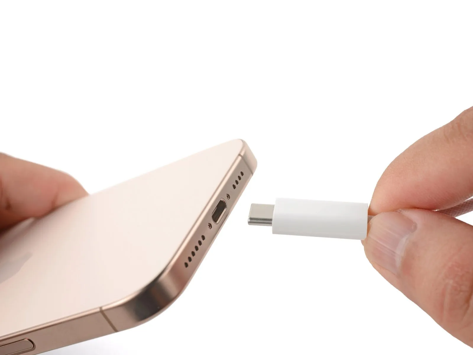
- Disconnect all external cables from the iPhone.
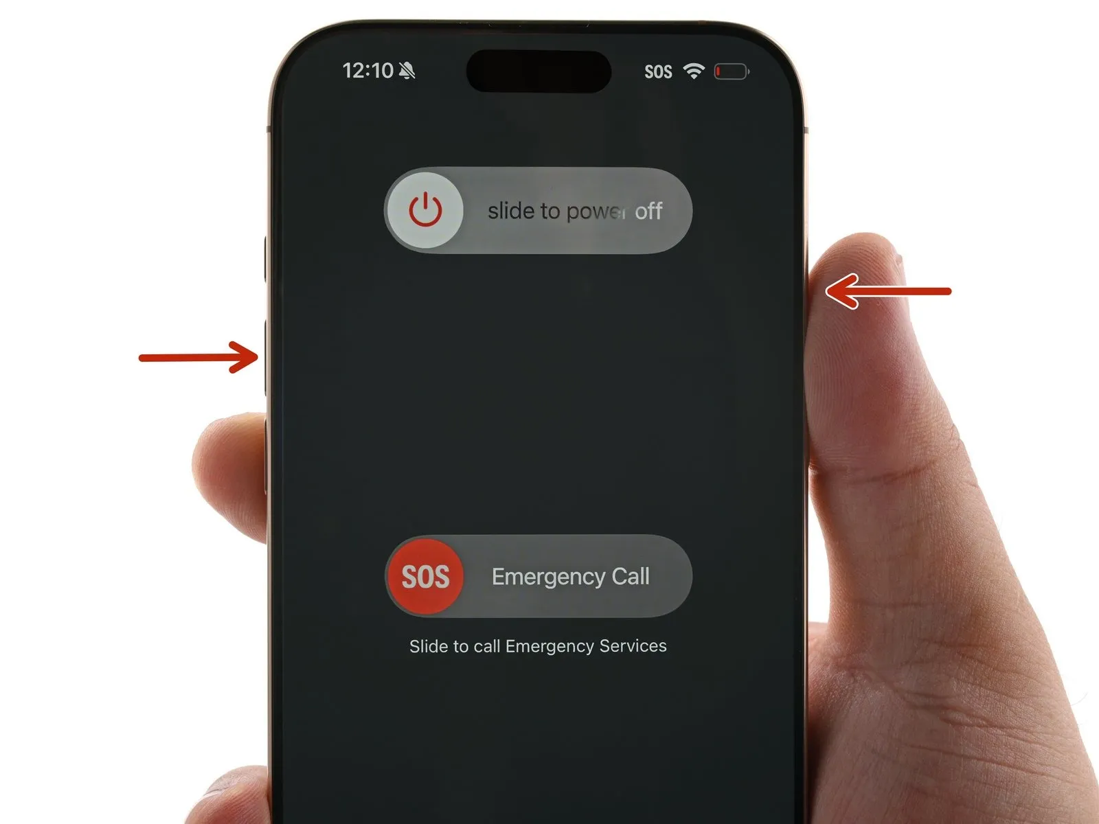
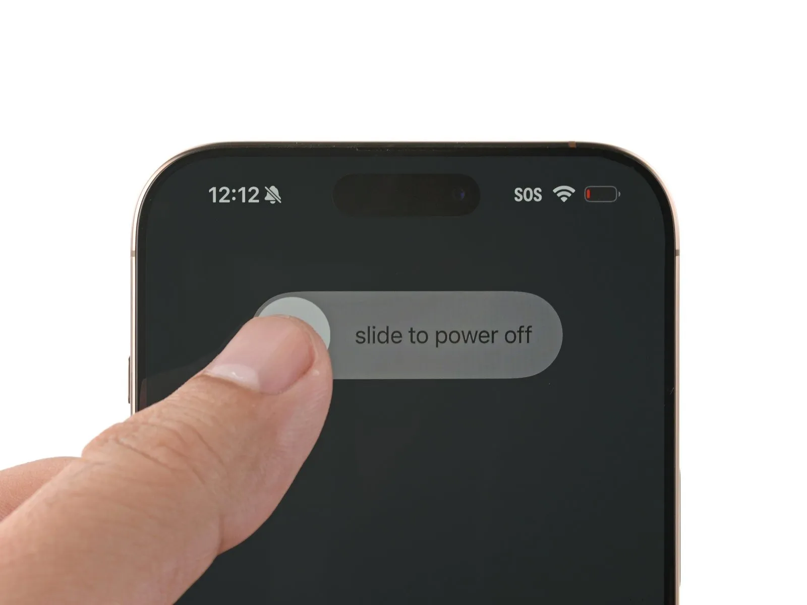
- Simultaneously press and maintain the power button and one of the volume buttons, then slide your finger to deactivate the device.
Step 2 | Tape over any cracks
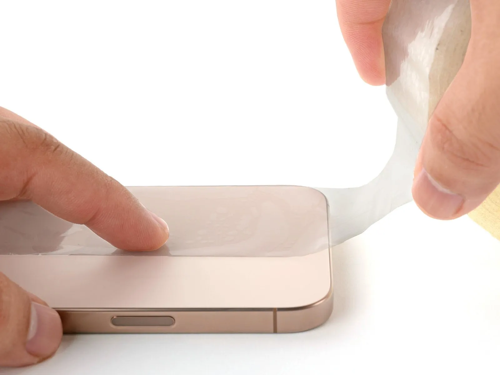
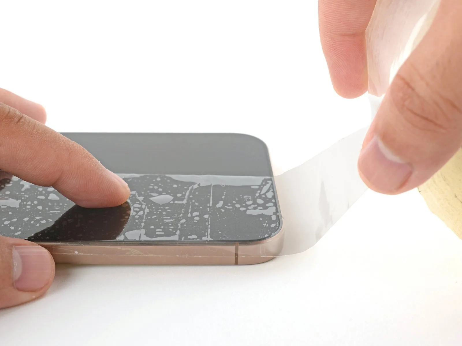
- To prevent injury and simplify the repair process when the display or rear glass exhibits severe cracking, apply strips of packing tape, ensuring they overlap, across the damaged areas.
- Ensure a flat surface, measuring sufficiently to accommodate a suction cup's adhesion, exists close to the lower border.
Step 3 | Remove the pentalobe screws
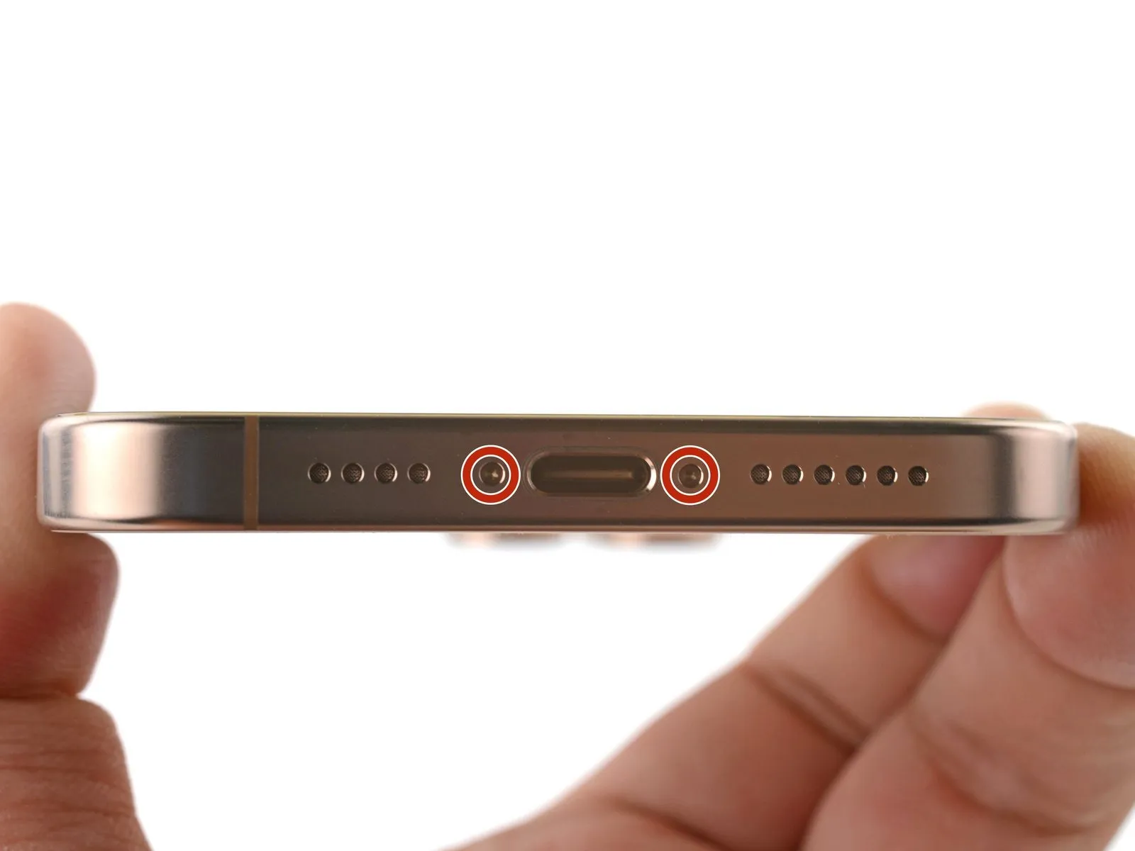

Employ a 3/8-inch socket wrench to loosen the retaining bolt, ensuring you maintain a firm grip and observe the torque specification of 15 Nm to prevent damage to the component.Use a P2 driver with a pentalobe tip.Detach the pair of fasteners.Screws measuring 7.4 millimeters in length.Flanking the charging port are two locations.
Step 4 | Mark your opening picks


- Excessive insertion of the opening pick may result in device damage.
- To avoid potential damage, use a marker to clearly identify the pick.
- Determine the dimension using a suitable measuring tool.Three millimeters.Using a permanent marker, indicate the opening point on the pick.
- Alternative corner markings, using the same measurement tools, can be applied to the remaining corners of the pick.
- Securely affix a coin to the tip of a pick using adhesive tape.Three millimeters.Beginning at the very end.
Step 5 | Create a gap using a suction handle
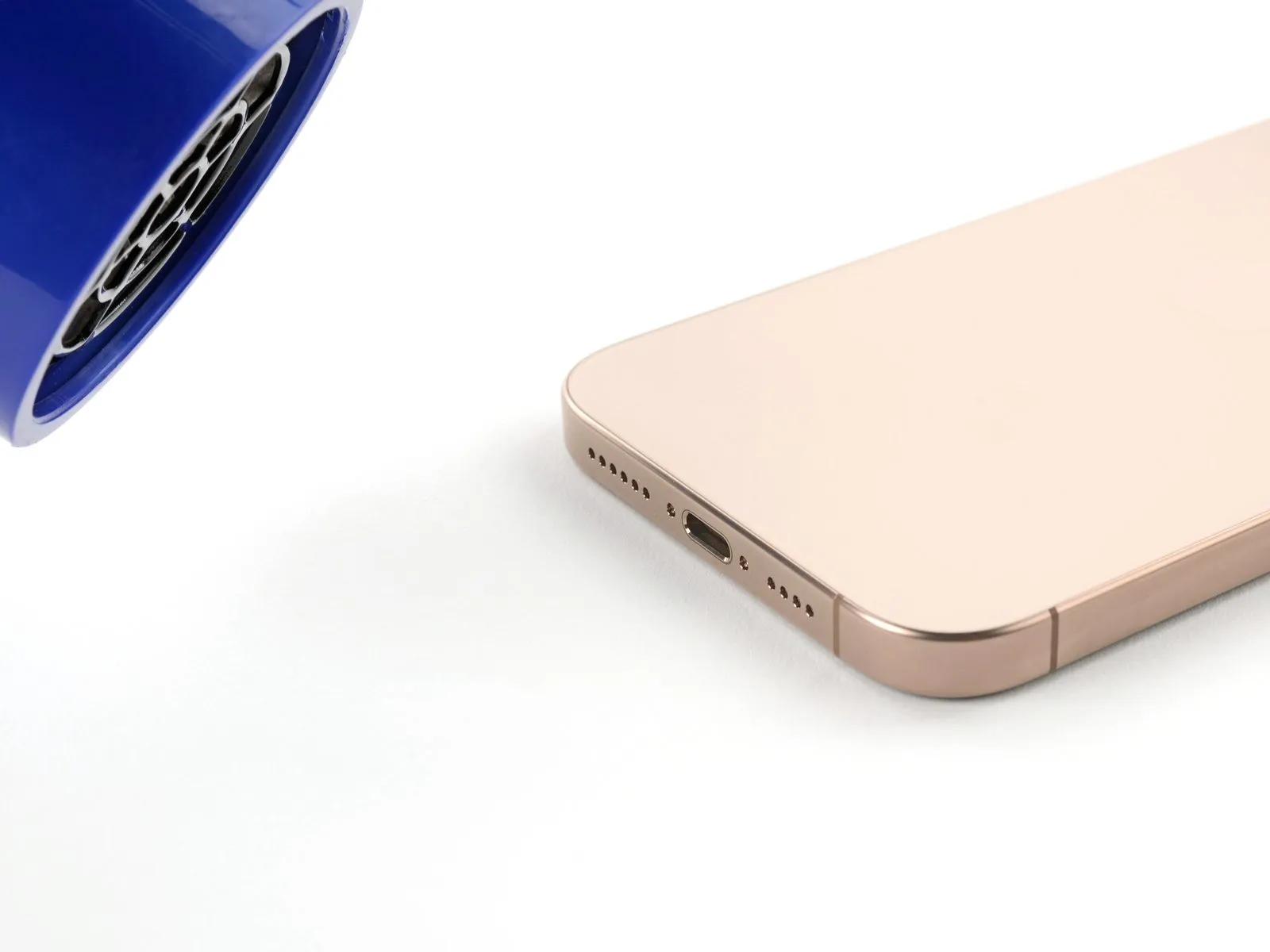
- Employ a suction handle to establish a starting space, as detailed in the following procedures.
- Employ a 3/8-inch socket wrench to tighten the fastener to a torque of 15 Nm, ensuring no damage occurs to the surrounding components and observing all safety precautions.Utilize a device designed to emit warm, directed airflow, ensuring the unit's wattage is consistent with 1200W and its cord length does not exceed 1.8 meters, while maintaining a safe operating distance of at least 6 inches from the component being dried.orApply warmth with a device capable of generating directed heat.Apply heat to the lower perimeter of the rear glass panel until its surface is warm enough to be comfortably touched.
- Alternatively, employ aUse the iOpener to gently warm the adhesive securing the display assembly.Apply warmth to the rear glass panel.
- To properly install, warm the adhesive backing and then press the component firmly into place, adhering to all specified dimensions and precautions.Use a specialized tool designed for electronics repair, often referred to as an iOpener, to gently warm the adhesive securing the device's casing.Ensure correct alignment and secure fastening according to specifications.
Step 6


- Using a suction handle, secure it firmly to the lower edge of the rear glass panel.
- Apply firm, consistent upward pressure to the handle to separate the rear glass from the frame.
- Increase the temperature being applied to the edge and repeat the process until a separation is visible.
- Carefully slide the pointed end of a prying tool into the separation.
Step 7 | Back glass information
- During the subsequent steps of separating the rear glass, ensure the tool remains shallow, never exceeding a depth of 3mm.Three millimeters.Exercise caution to prevent harm to these components.
- To prevent damage, avoid inserting tools near the volume up button, as this area houses a fragile cable linking the rear glass assembly to the iPhone.
- The iPhone incorporates numerous spring-loaded electrical contacts arranged circumferentially.
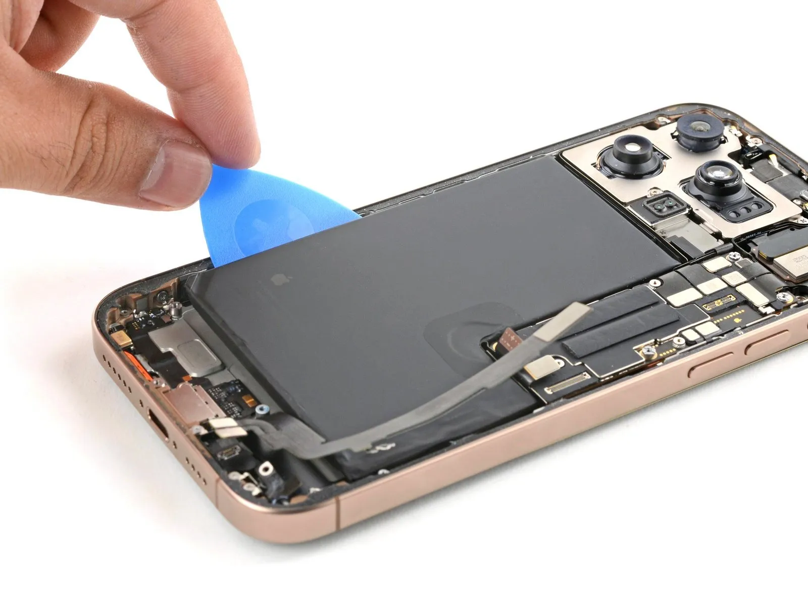
Step 8 | Separate the bottom edge adhesive

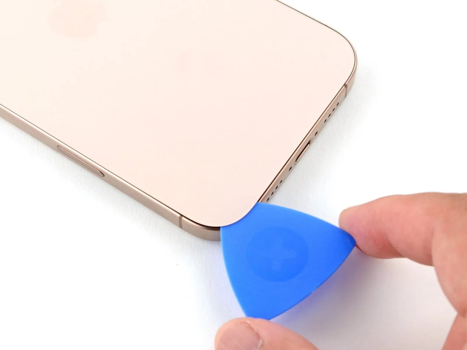
- Using a pick, carefully separate the adhesive bond by gently working it along the lower perimeter.
- To ease cutting, apply heat to the adhesive edge for one minute and retry the slicing process.
- Maintain a gap in the lower left corner using the provided pick to stop the adhesive from bonding shut.
Step 9 | Heat the left edge
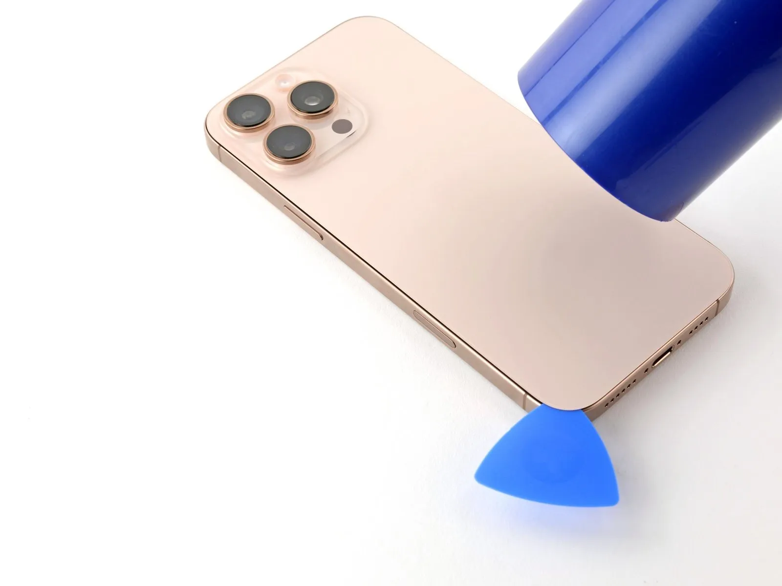
Apply warmth with a hair dryer or heat gun.Apply warmth to raise the temperature.Apply heat to the left side of the rear glass panel until its surface temperature is high enough to be felt as hot when touched.
Step 10 | Separate the left adhesive

- Position another opening pick near the first, specifically in the lower-left corner.
- Avoid pushing the tool beyond the specified depth.Three millimeters.Exercise caution to prevent harm to the spring contacts.
- Using a pick, carefully work along the left side, releasing the metal clips while breaking the adhesive bond.
- As the clips slide past, you will notice and sense them disengaging.
- To stop the adhesive from bonding prematurely, maintain the presence of the pick in the upper-left corner.
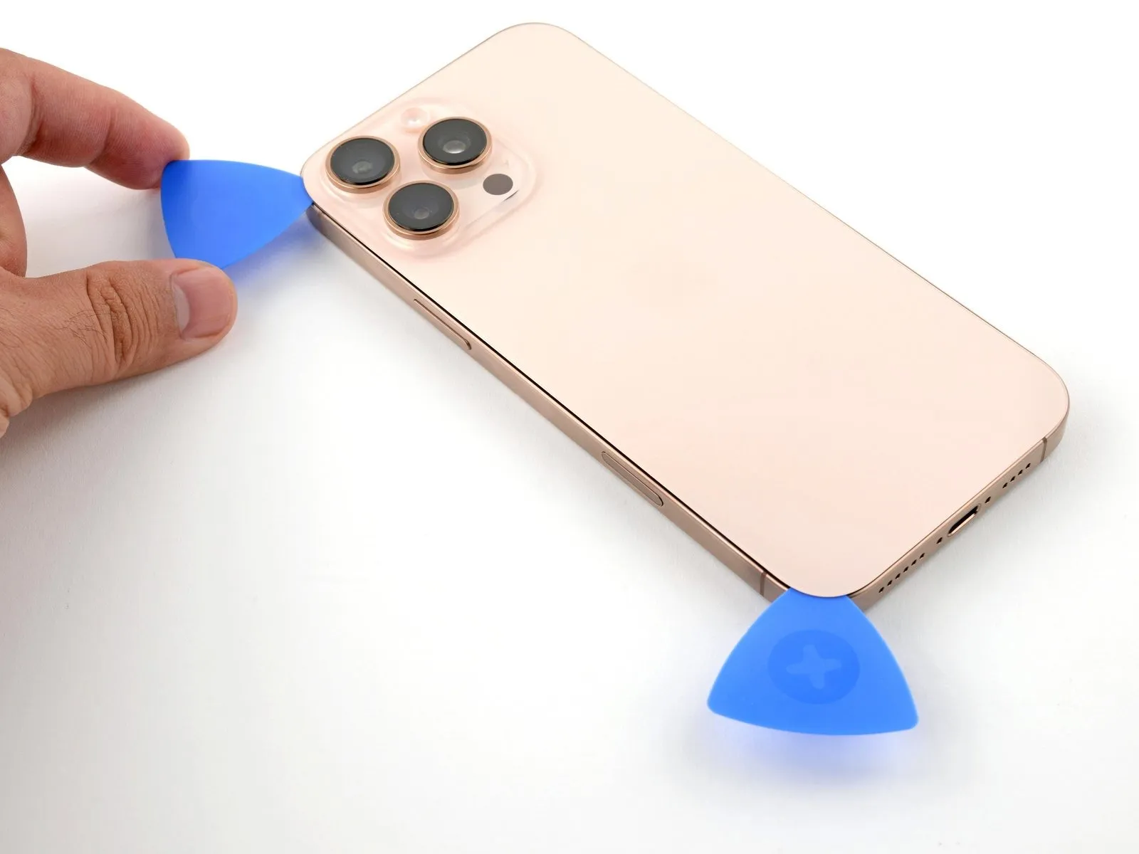
Step 11 | Heat the top edge and corner

Apply warmth with a hair dryer or heat gun.Apply warmth, ensuring the temperature reaches a maximum of 150 degrees Fahrenheit, using a heat gun or hairdryer.Apply heat evenly across the back glass's upper edge and the upper-right corner, ensuring these areas reach a temperature detectable by touch.
Step 12 | Separate the top adhesive

- Ensure the pick's insertion depth does not exceedThree millimeters.Exercise caution to prevent harm to the spring contacts.
- Using a third opening pick, position it within the top-left corner.
- Using the opening pick, carefully maneuver it along the device's upper edge, progressing around the top-right corner until it rests positioned directly above the volume up button.
- Maintain the pick's position within the gap to stop the adhesive from bonding together.
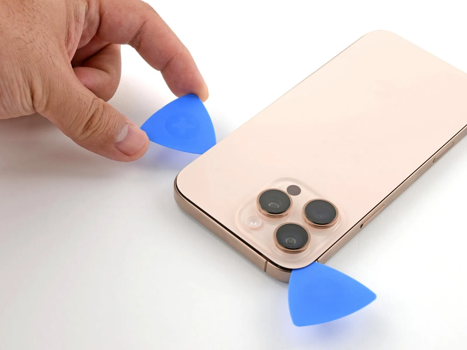
Step 13 | Heat the right edge

Step 14 | Separate the right adhesive


- Position a fourth opening pick within the lower-rightmost corner.
- Position the opening pick along the device's corner, then move it upward along the right side, pausing just beneath the volume down button.
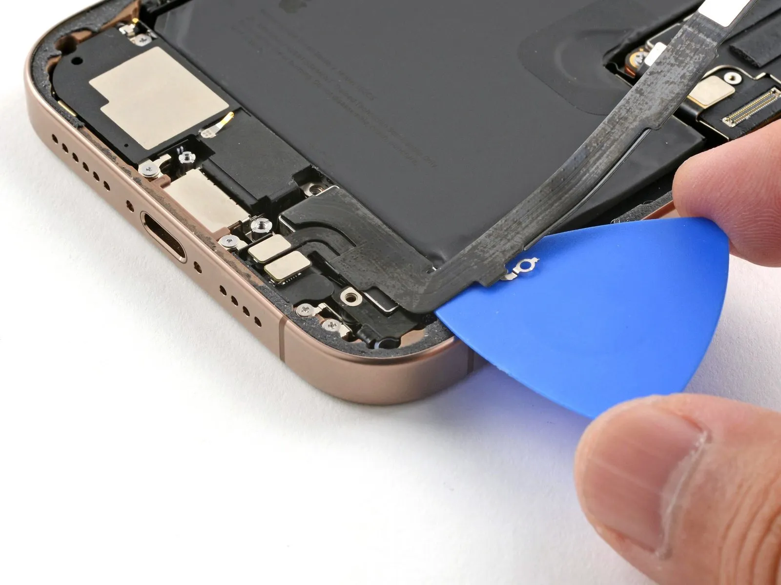
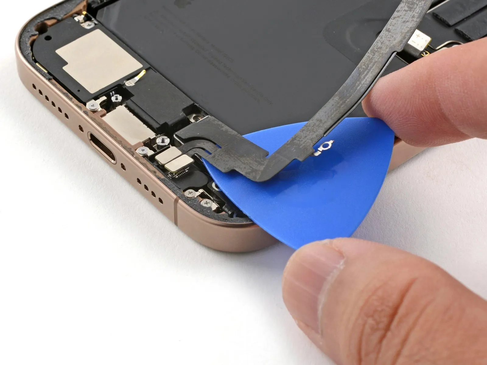
Step 15 | Reposition the back glass

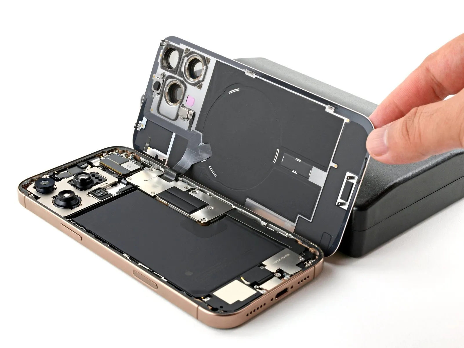
- Carefully pivot the rear glass cover away from the iPhone body on its right side to release the remaining adhesive bond.
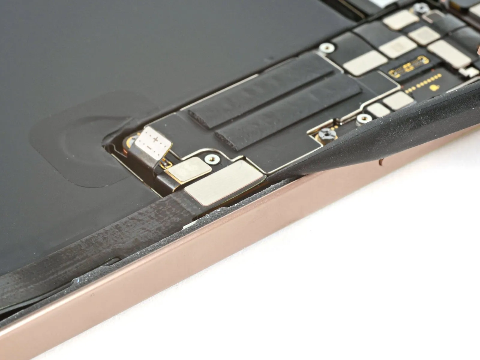
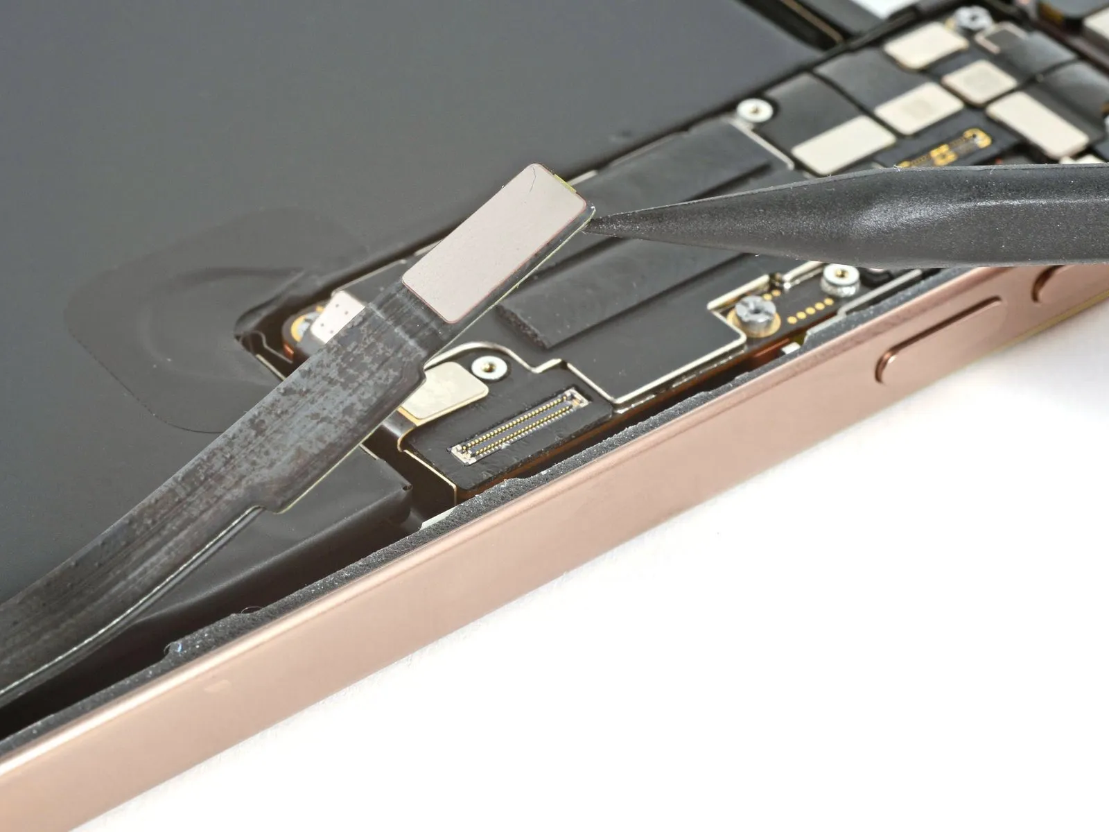
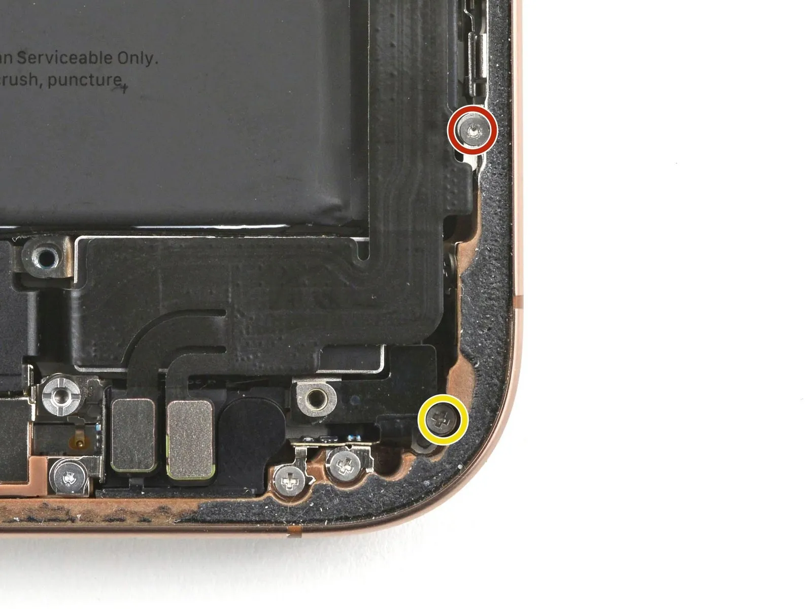
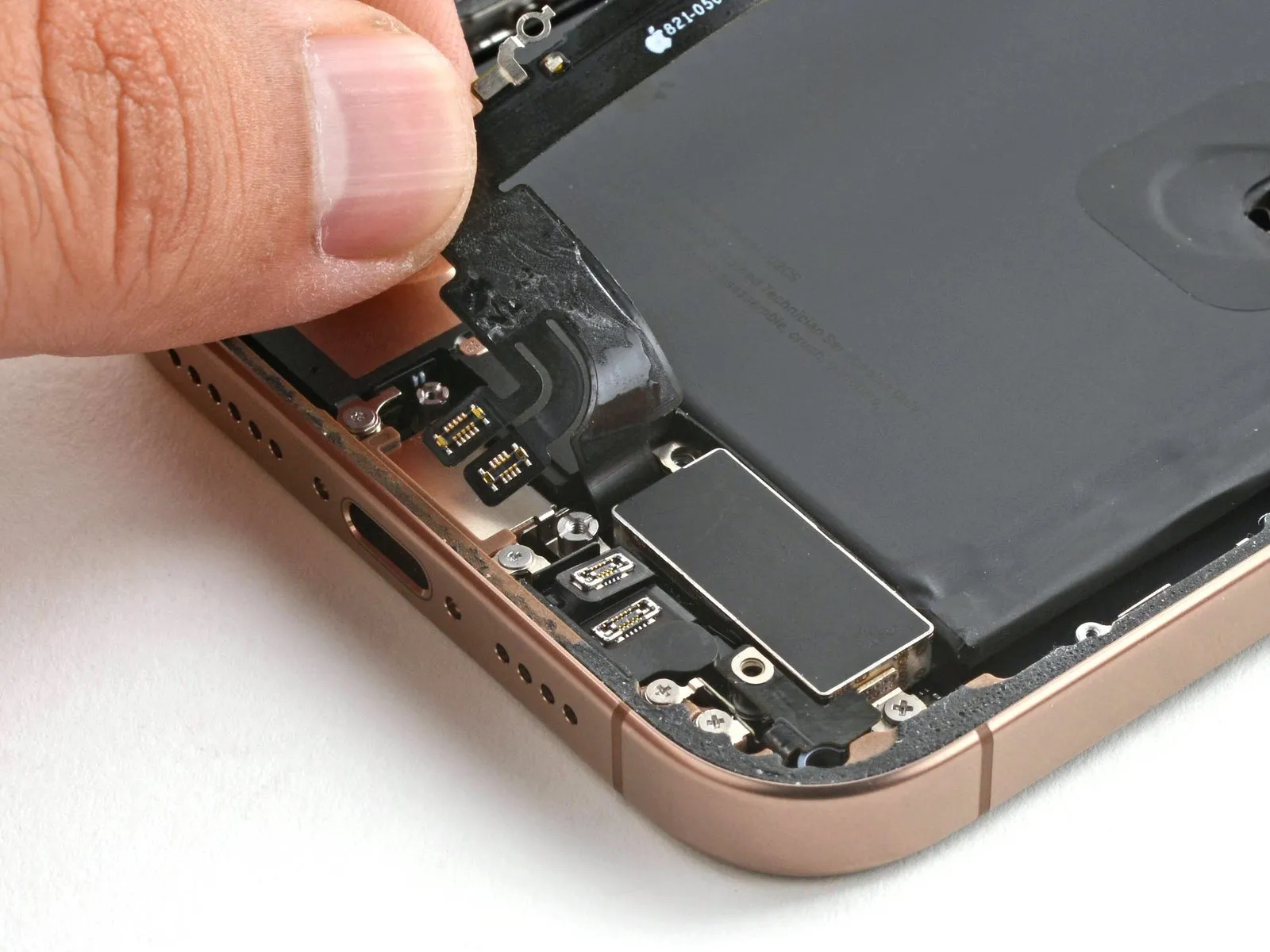
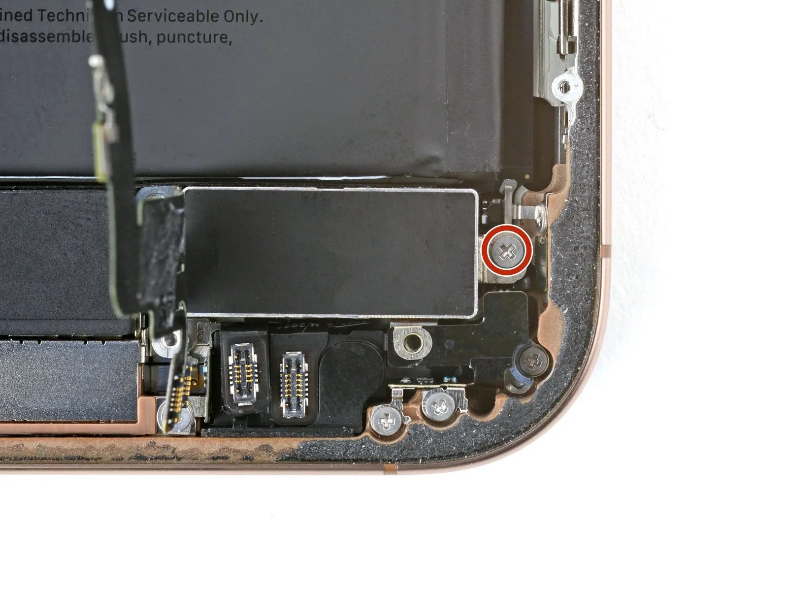
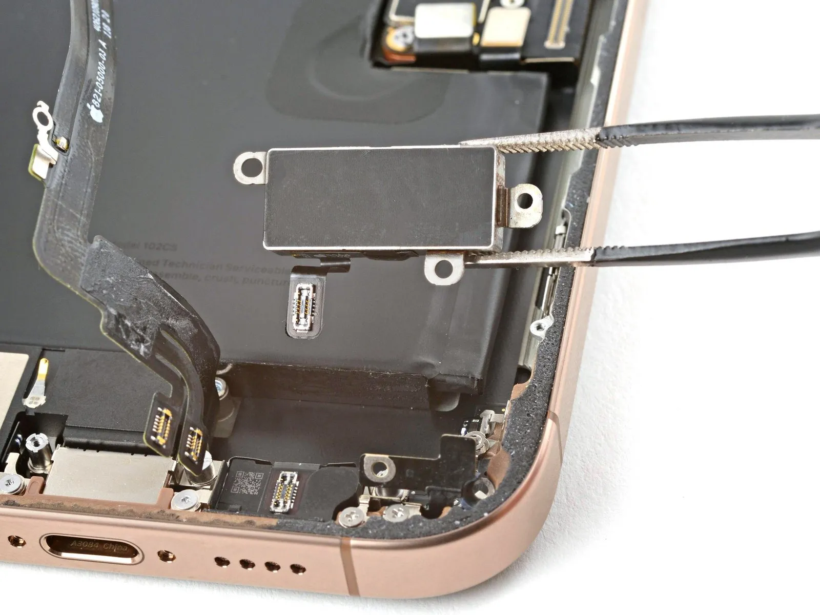
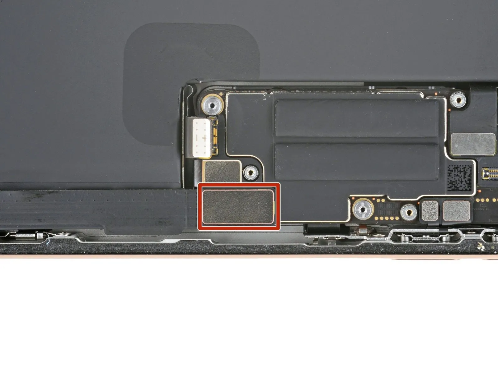
Step 16 | Remove the battery connector cover

- Use two screws, each measuring 1.3 millimeters in length.
- A screw, measuring 1.0 millimeters in length, is required.
Step 17

Step 18 | Disconnect the battery
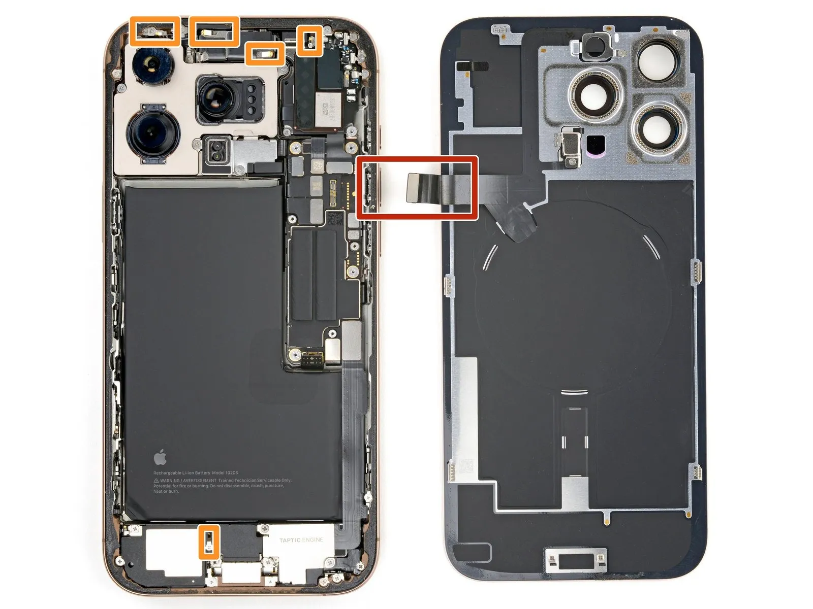
Step 19 | Remove the back glass connector cover

- Employ a quantity of two.One point three millimeters.Use screws with a length of the specified dimension.
- Use a quantity of two.One millimeter.Utilize screws with a length designated as "long."
Step 20
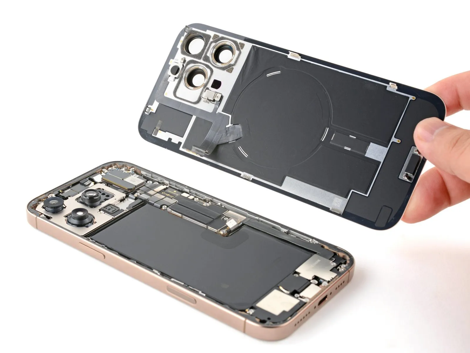
Step 21 | Remove the back glass
Step 22
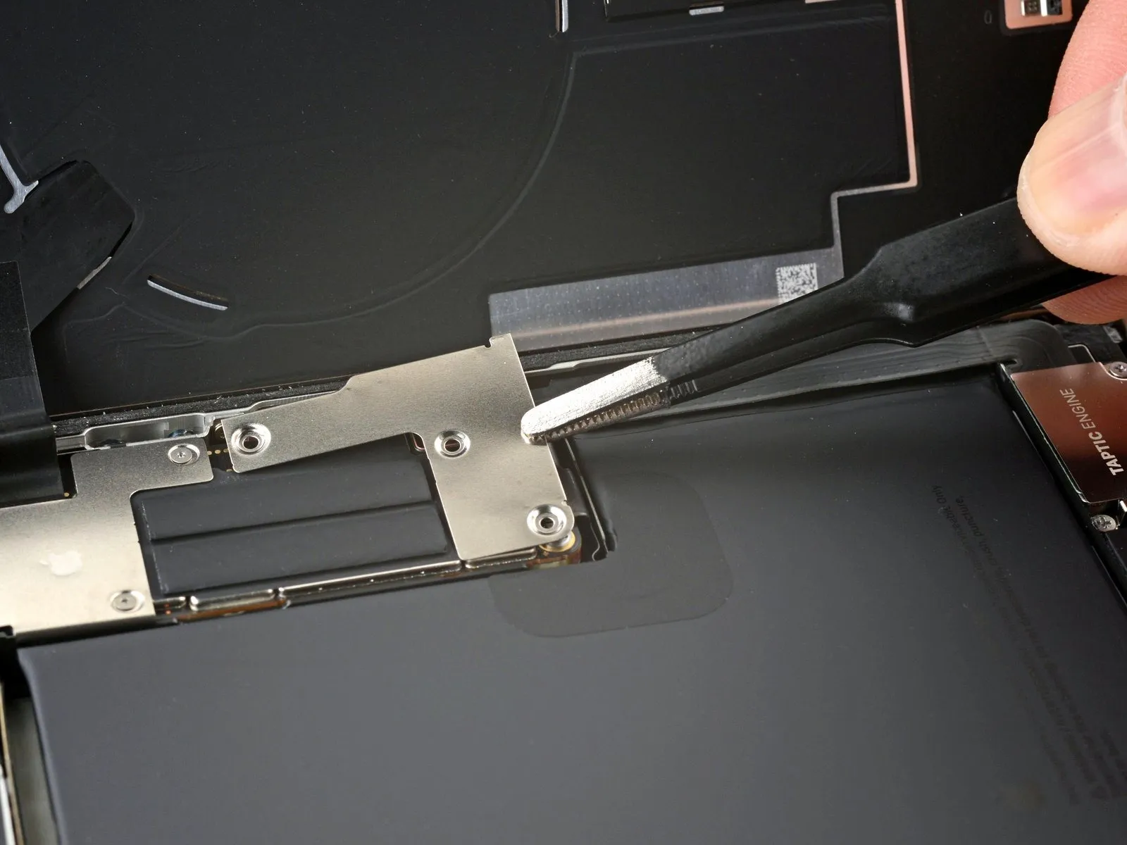
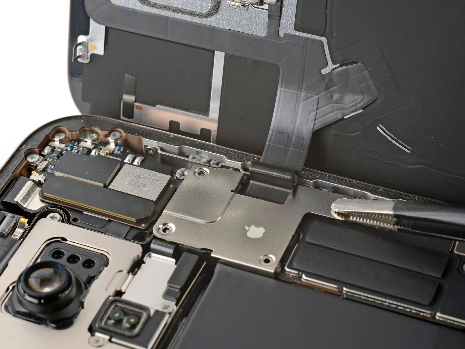
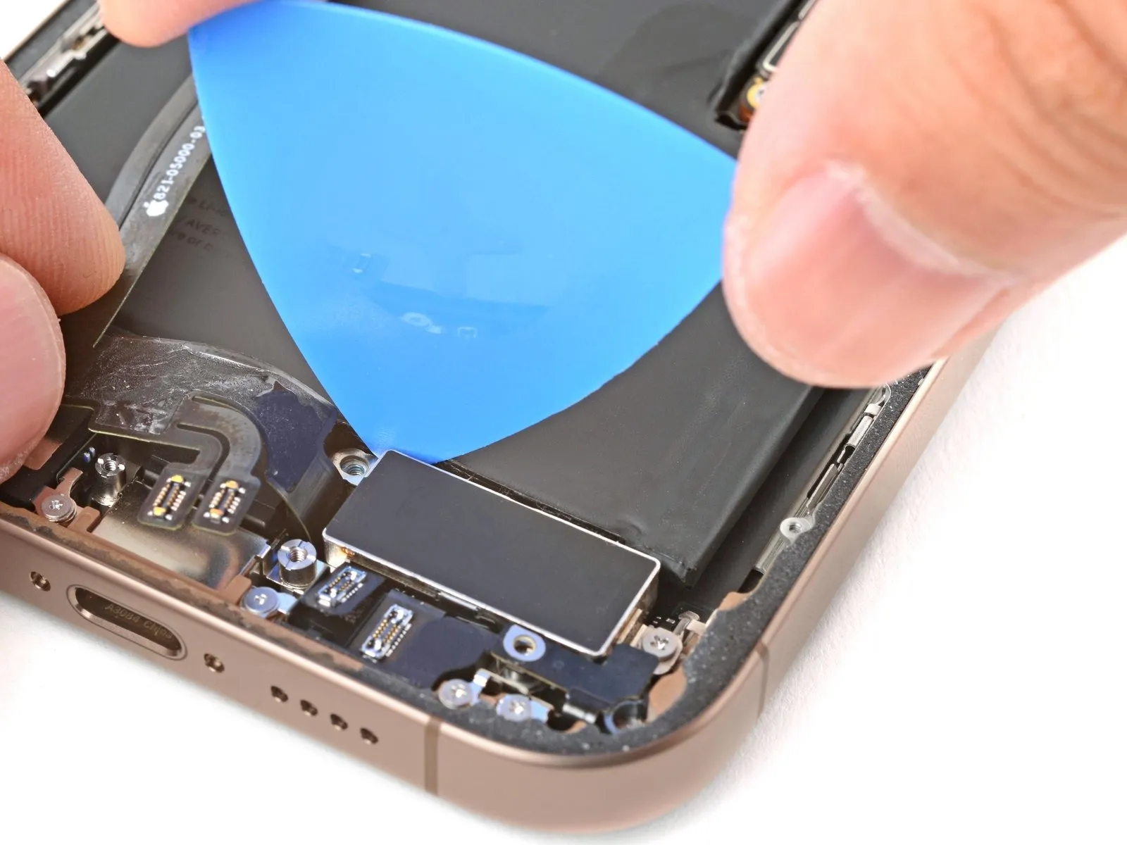
Step 23 | Remove the Taptic Engine cover
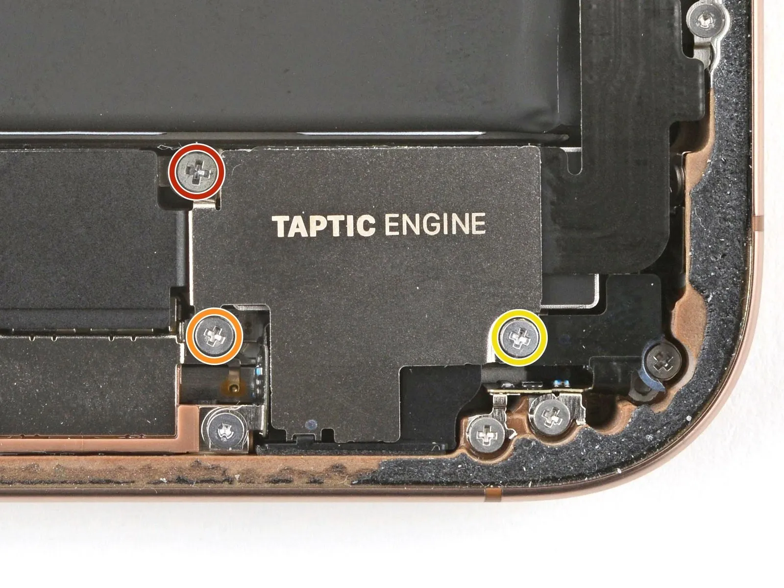

- Employ a 5/32-inch hex key to tighten the retaining screw to a torque of 6-8 inch-pounds, ensuring you do not overtighten and damage the threads.Use a Phillips-head screwdriver.Use a Phillips screwdriver to detach the Taptic Engine cover by unscrewing the three fasteners.
- A screw, measuring 2.9 millimeters in length, is required.
- A screw, measuring 1.3 millimeters in length, is required.
- A screw, measuring 2.4 millimeters in length, is required.
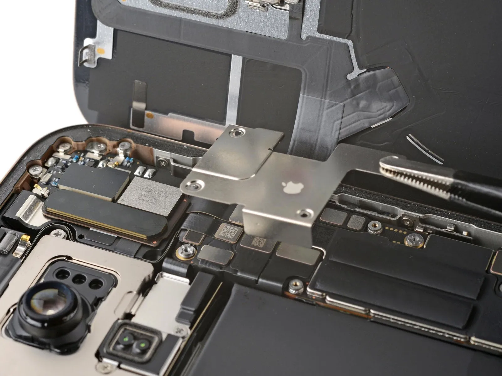
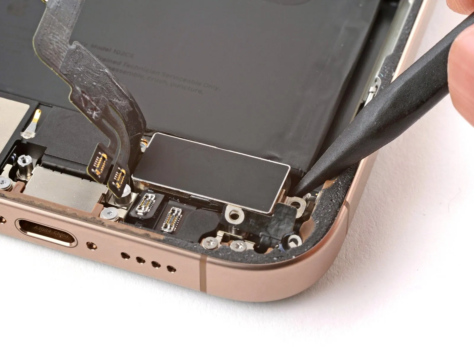
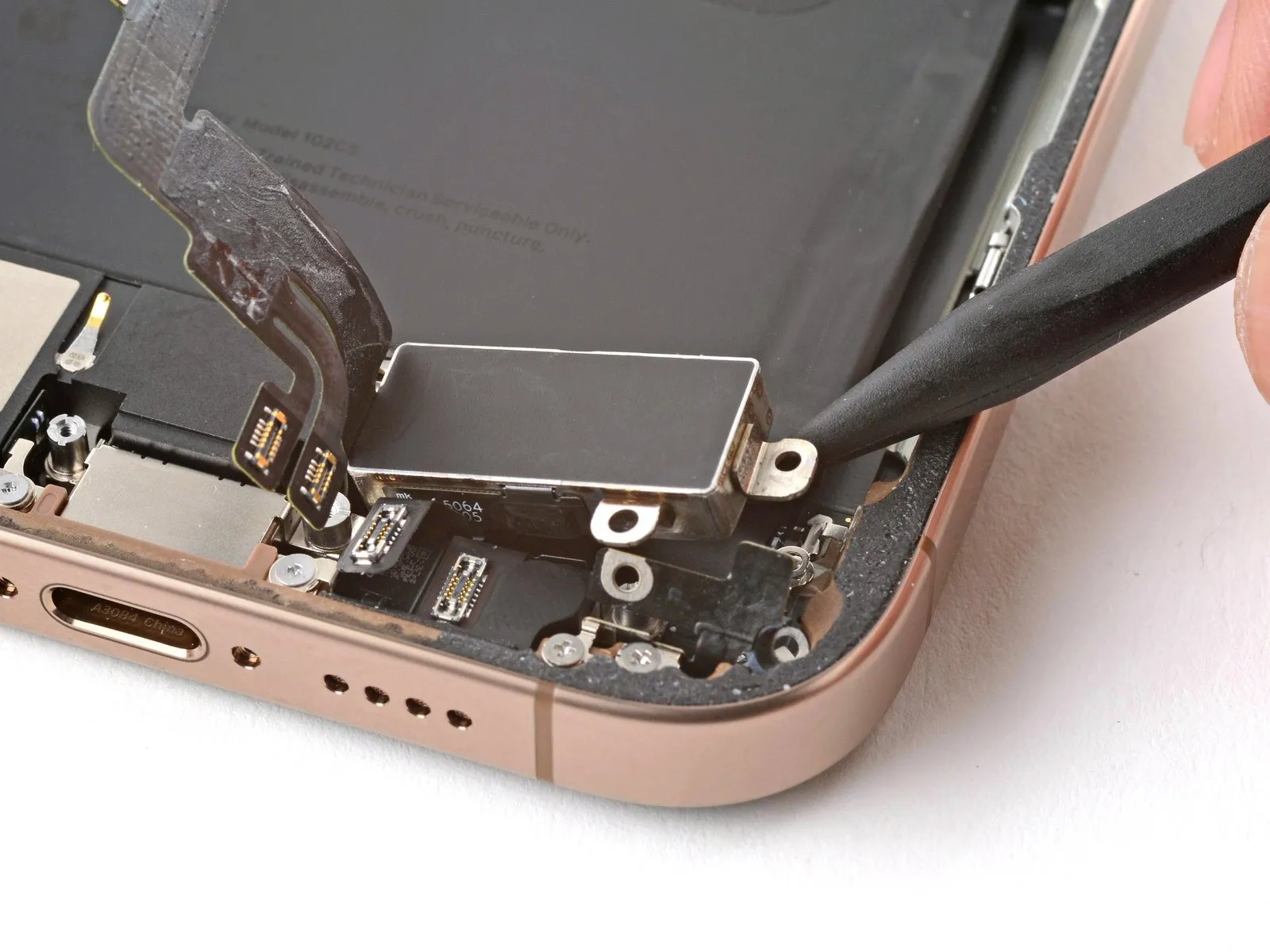
Step 24

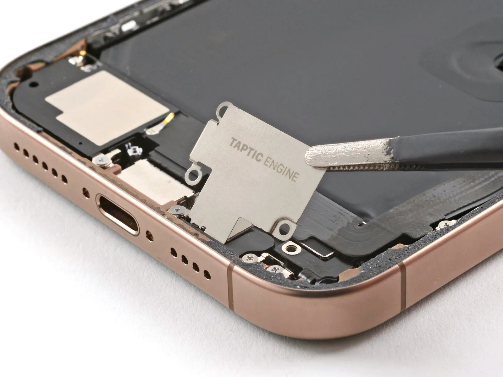

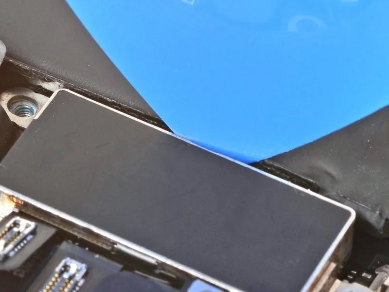
- Carefully raise the Taptic Engine cover's upper edge by gently prying with tweezers or your fingertips.
- After releasing the lower edge from the frame's securing latches, detach the Taptic Engine cover.
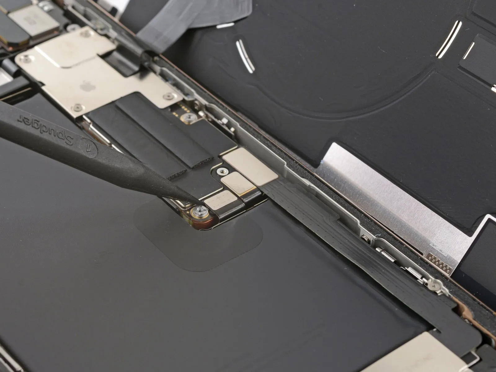
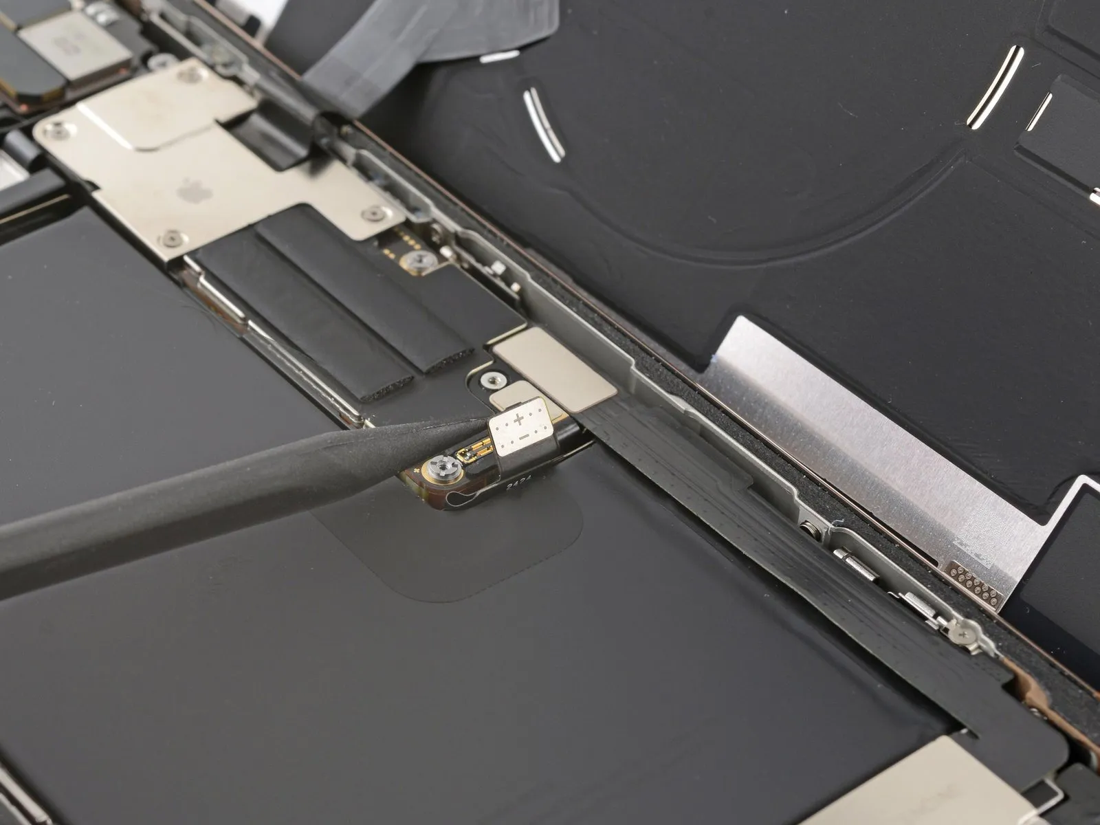
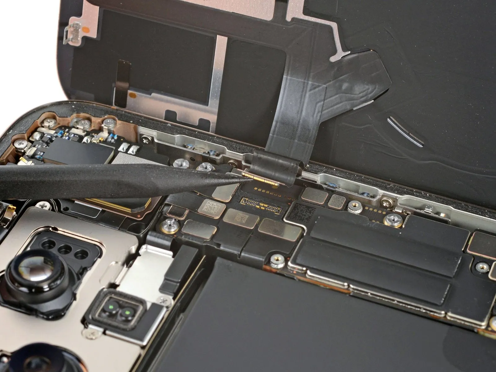
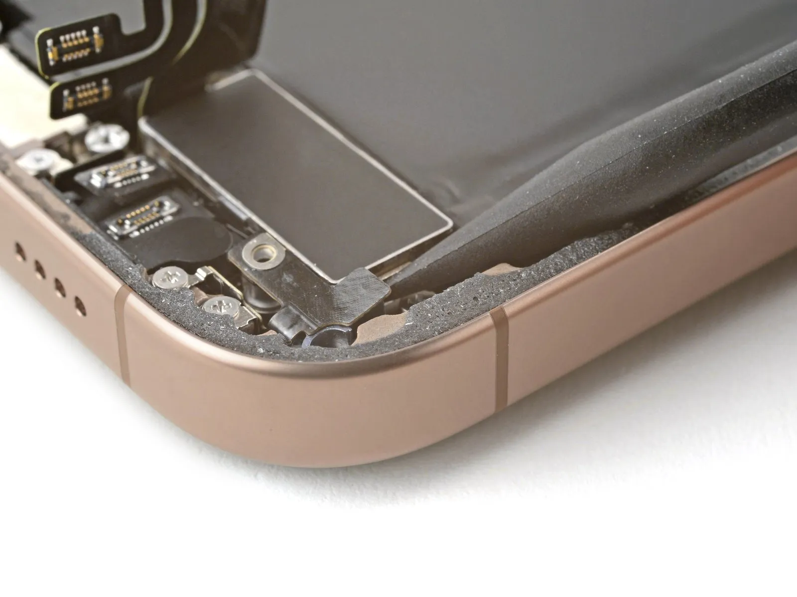
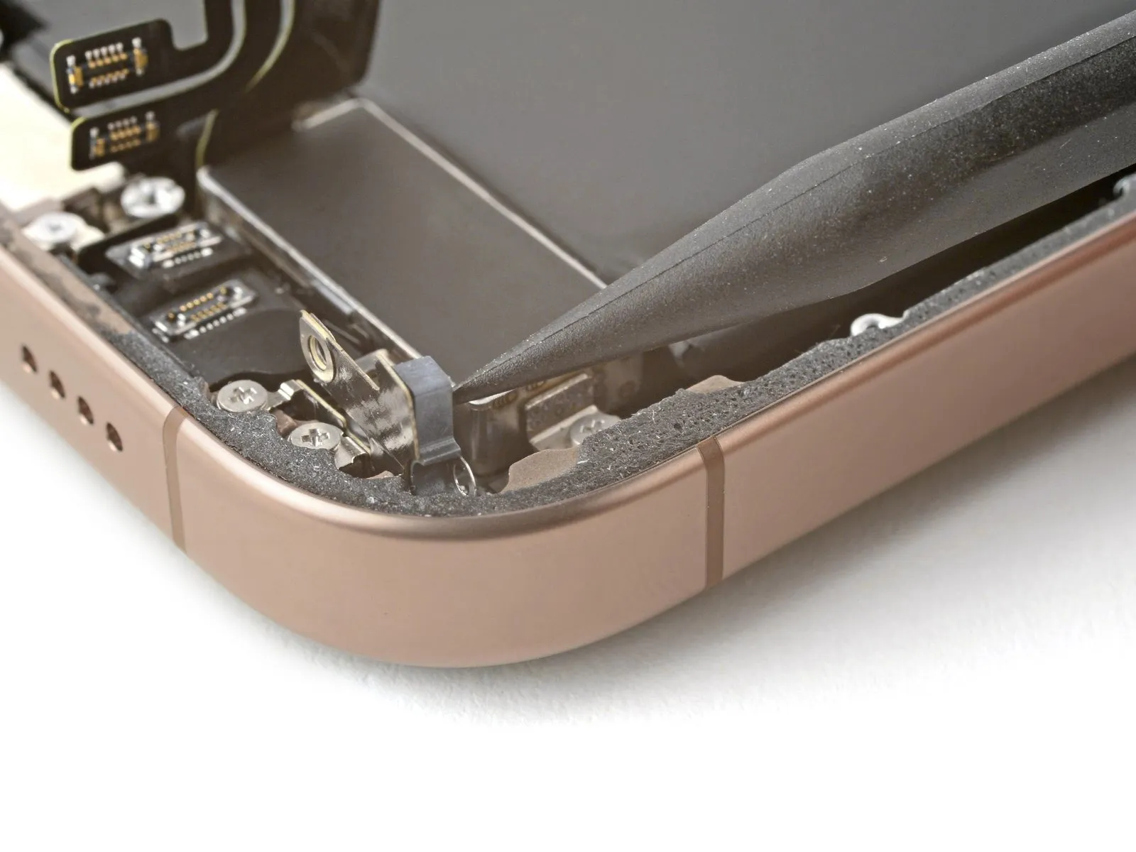
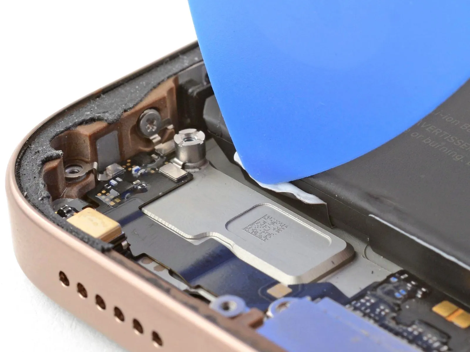
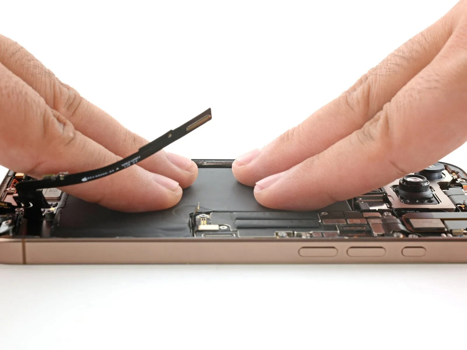
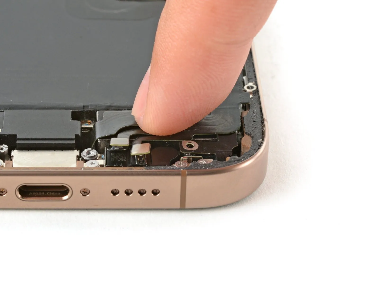
Step 25 | Loosen the lower assembly cable
- Carefully insert the tip of a screwdriver to.Use a plastic pry tool, often referred to as a spudger.Using a prying tool, carefully release and detach the cable connecting the lower assembly to the logic board.
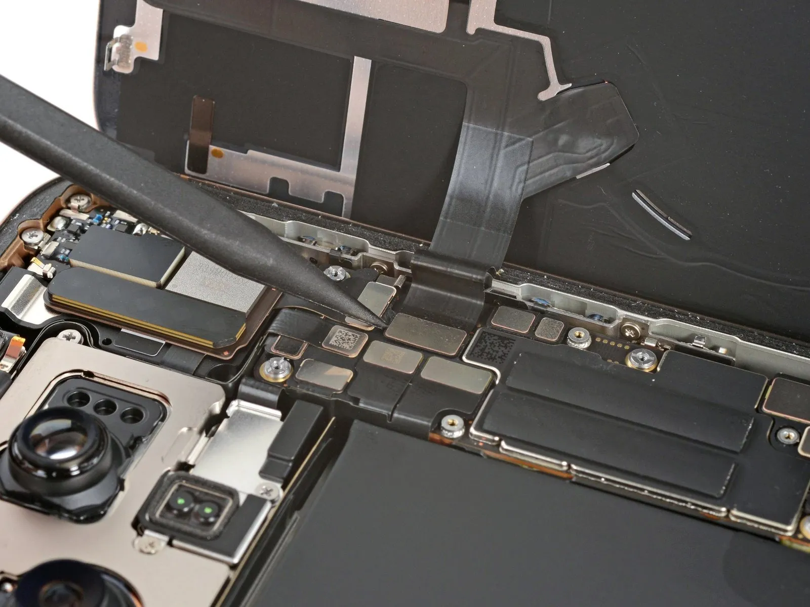
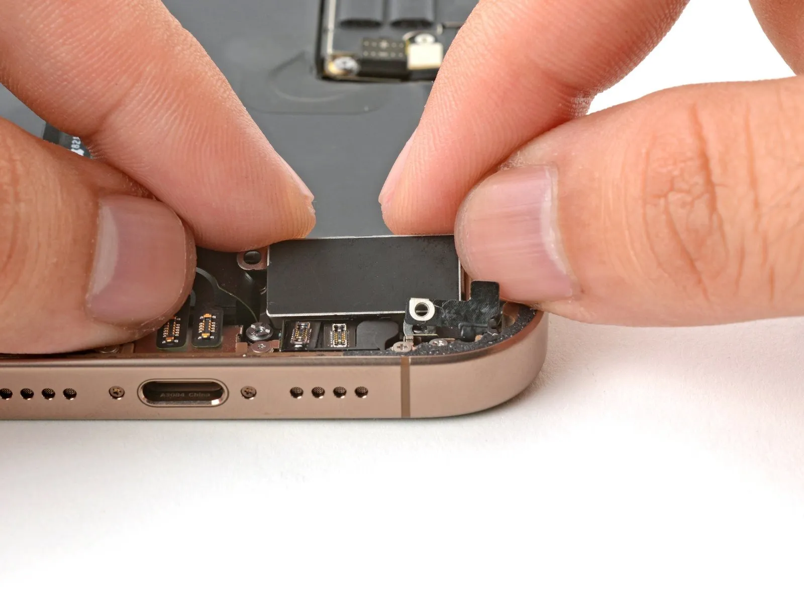
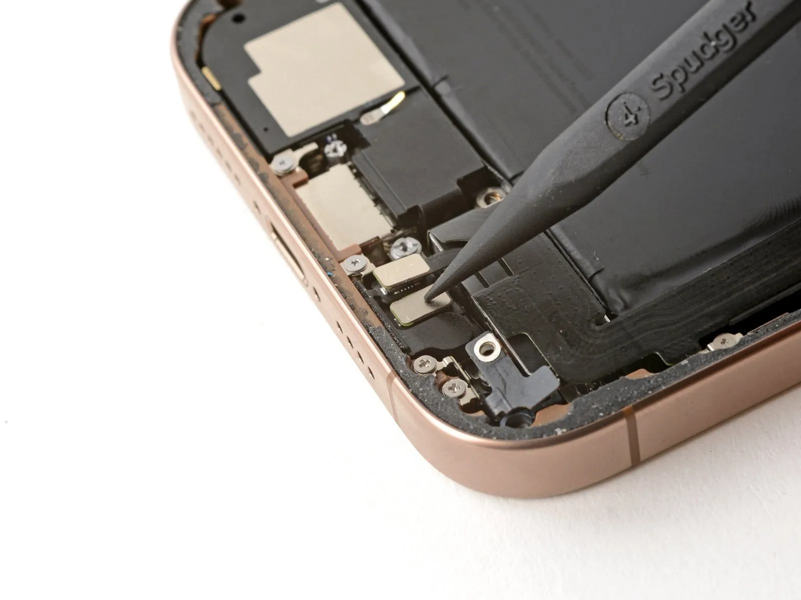
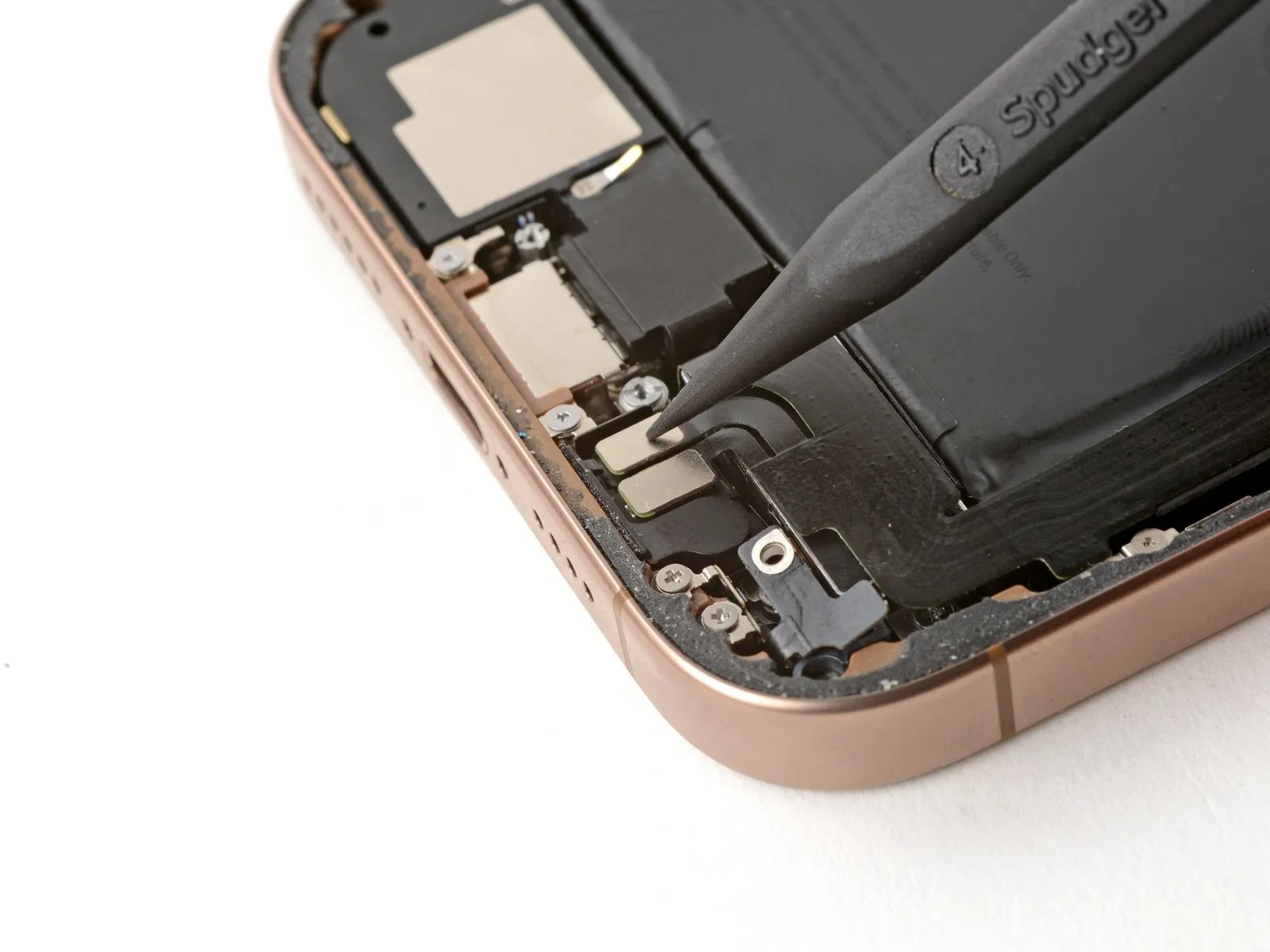
Step 26
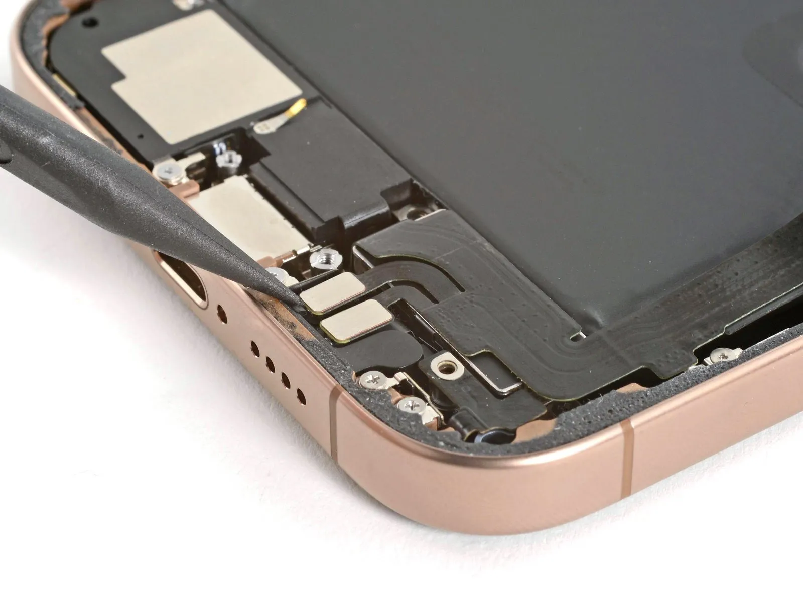

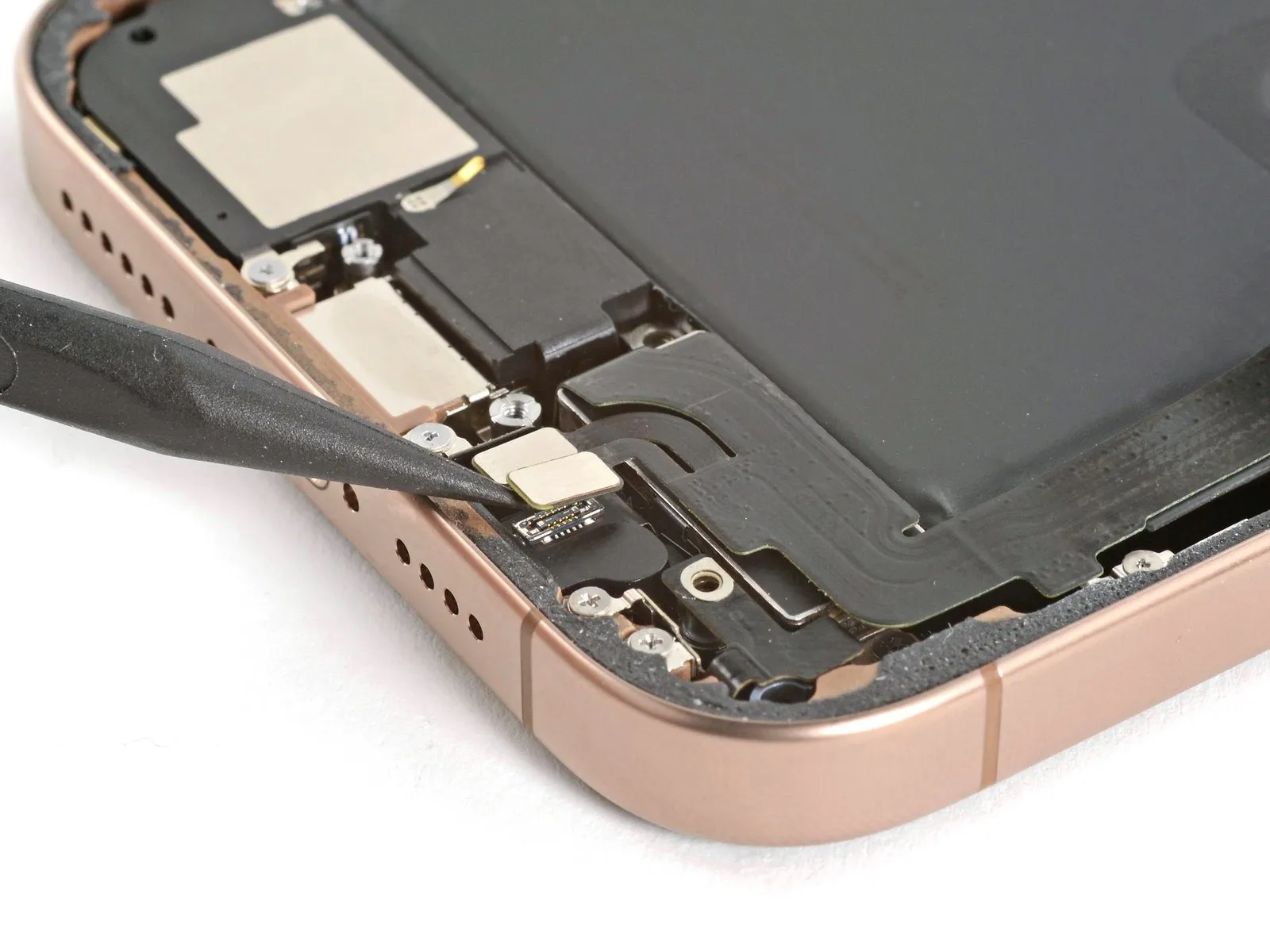
- Carefully insert the tip of a screwdriver to.Use a spudger.Carefully use a prying tool to release and separate the two connectors situated on the lower right side of the frame.
Step 27
- Detach the lower assembly cable by unscrewing the two fasteners.
Begin the process with the number one.A Y000 tri-point screwdriver is needed to remove a screw measuring 1.0 mm in length.
Begin the process by executing the action designated as "One."A Phillips head screw with a length of 1.3 millimeters.
Step 28

- Apply heat to the lower assembly's cable section, located above the Taptic Engine, using a hair dryer until the surface reaches a temperature that is noticeably warm when touched.
Step 29
- Carefully position the component so that it moves along the designated track.Use a specialized tool designed for prying, often referred to as an opening pick.Carefully detach the lower assembly cable from its connection.The haptic feedback actuator is referred to as the Taptic Engine..
- To gain access, gently maneuver the cable, ensuring it's clear of the work area.The device incorporates a Taptic Engine..
Step 30 | Remove the Taptic Engine
- Employ a 3/8-inch socket wrench to tighten the fastener to a torque of 15 Nm, ensuring that you observe all safety precautions and handle the component with care.Use a Phillips-head screwdriver.Detach the component.A screw measuring 2.1 millimeters in length.Ensure the component is firmly fixed.The device incorporates a Taptic Engine..
Step 31
- Carefully employ the tip of a screwdriver to apply pressure.Use a plastic pry tool, often referred to as a spudger, to avoid scratching surfaces.Raise the corner bracket by rotating it.
Step 32

- Carefully insert the tool's end intoUse a specialized tool designed for prying, often referred to as an opening pick.Position yourself so you can access the upper border.The device incorporates a Taptic Engine.Carefully detach the plastic buffer strip, which is bonded to the component.
Step 33
- Carefully employ the tip of a screwdriver to apply pressure.Use a plastic pry tool, often referred to as a spudger, to avoid scratching surfaces.Carefully lever the component upward.The device incorporates a Taptic Engine..
- Avoid applying force that could damage the housing by ensuring the tool does not contact the enclosure during separation.Carefully disconnect the battery, observing proper polarity to avoid short circuits, and ensure the terminals are clean before proceeding; replacement requires a 12-volt, 400 cold-cranking amp (CCA) battery, and use caution to prevent acid exposure while handling..
- Carefully detach the component, ensuring all original specifications and dimensions are maintained.The device incorporates a Taptic Engine..
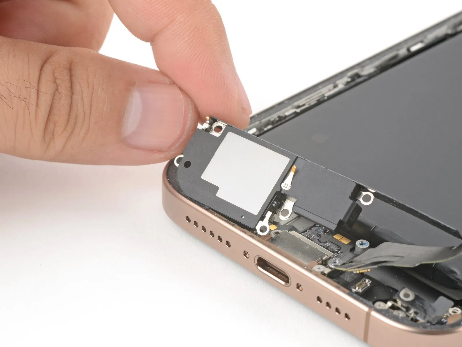
Step 34 | Remove the loudspeaker

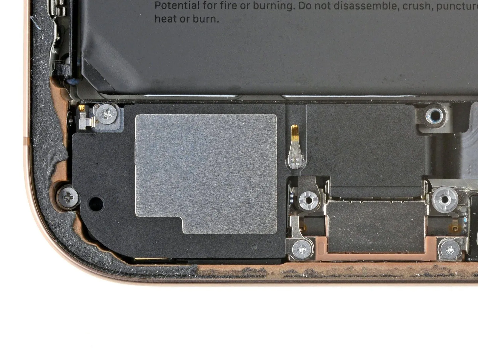
- Using a screwdriver, detach the loudspeaker by unscrewing the four fasteners that hold it in place.
- Use a unit of measurement equal to one.A Phillips screwdriver is needed to tighten or loosen a screw measuring 1.7 millimeters in length.
- Use a single unit.A Phillips head screw measuring 1.5 millimeters in length.
- Use a single unit.A screw with a length of 4.1 millimeters.
- Use a single unit.A Y000 tri-point screwdriver is needed to remove a screw measuring 1.3 millimeters in length.
Step 35
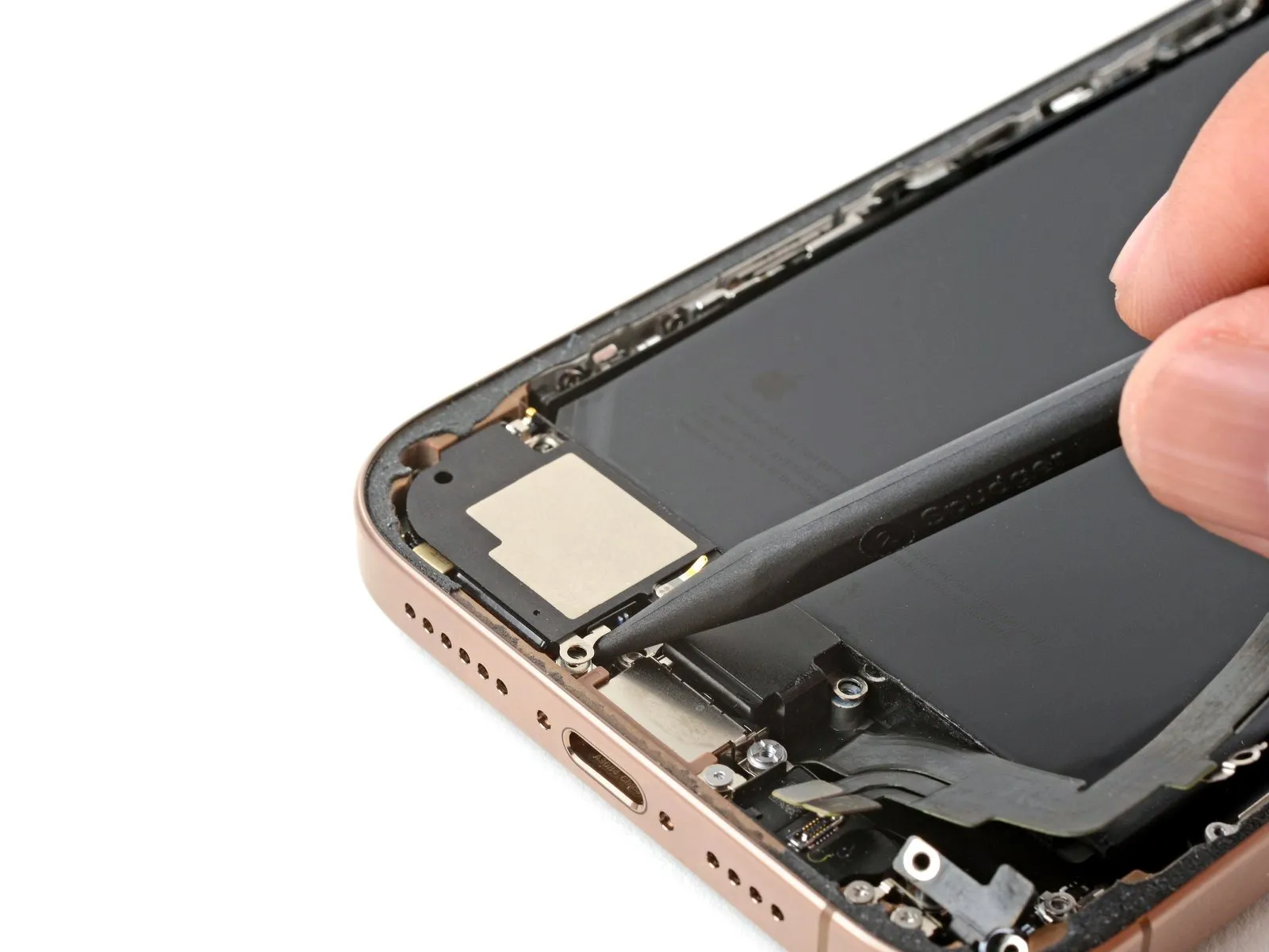
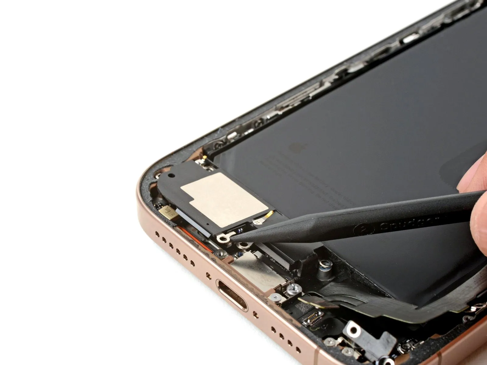
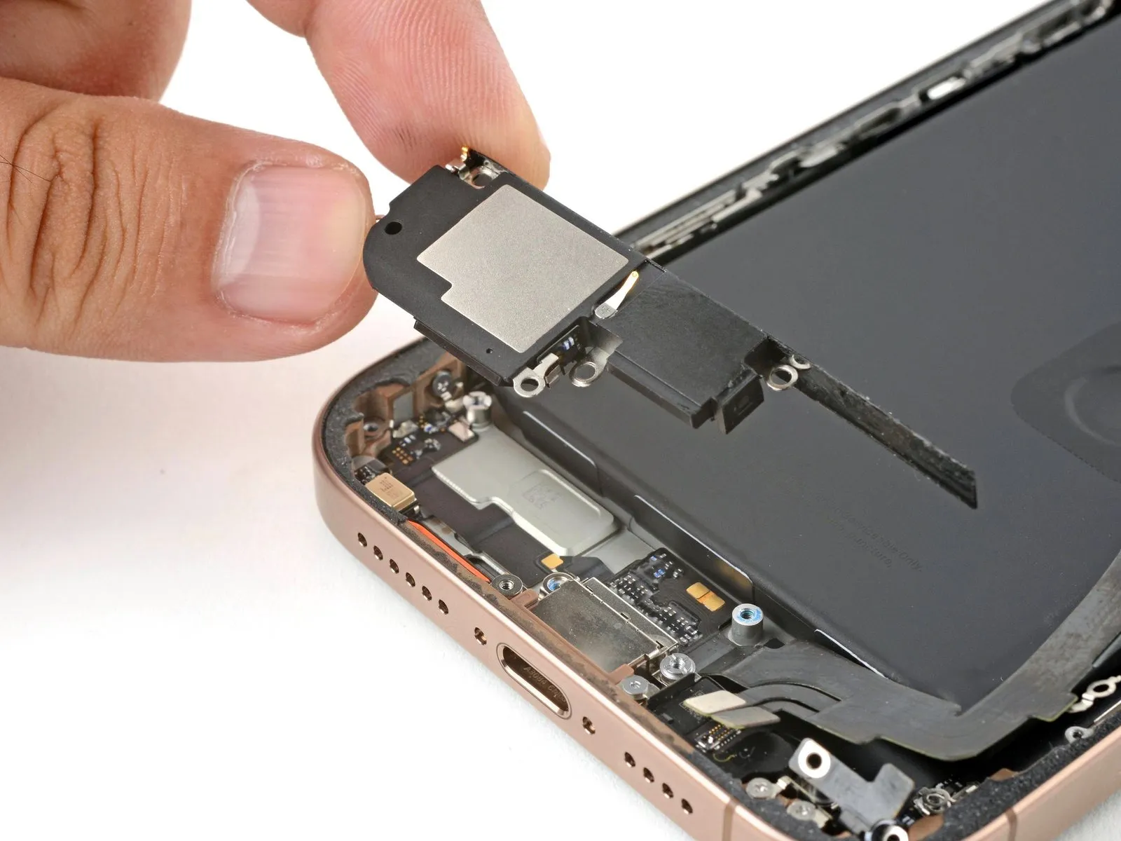
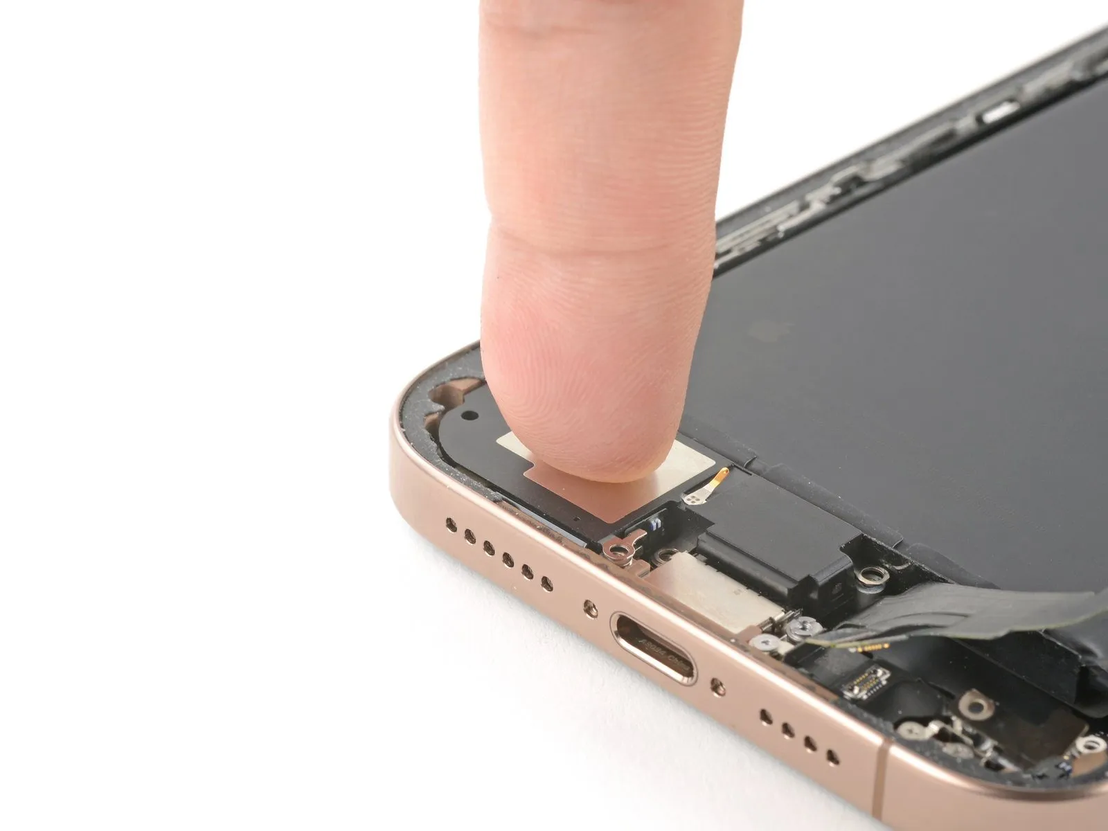
- Carefully position the tip of aUse a plastic pry tool, often referred to as a spudger, to gently separate components.Locate the screw hole situated on the lower right side of the loudspeaker's base.
- Using a prying tool, carefully disengage and extract the loudspeaker.
Step 36 | Battery adhesive information

To detach the iPhone battery, carefully release the three adhesive strips holding it in place, following the subsequent four procedures.
Exercise caution to avoid any damage, such as indentations or holes, to theCarefully disconnect the battery, observing polarity to avoid short circuits, and ensure proper grounding during removal to prevent electrical shock; the battery is rated at 12 volts and utilizes a standard group size 24 terminal configuration, requiring a 10mm wrench for connection/disconnection, and must be handled with insulated gloves to prevent personal injury from acid exposure.Exercise caution and do not employ cutting implements in the vicinity of the component.
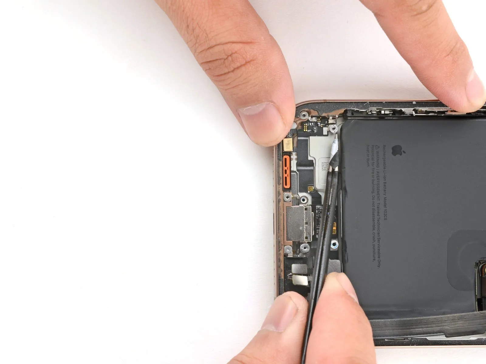
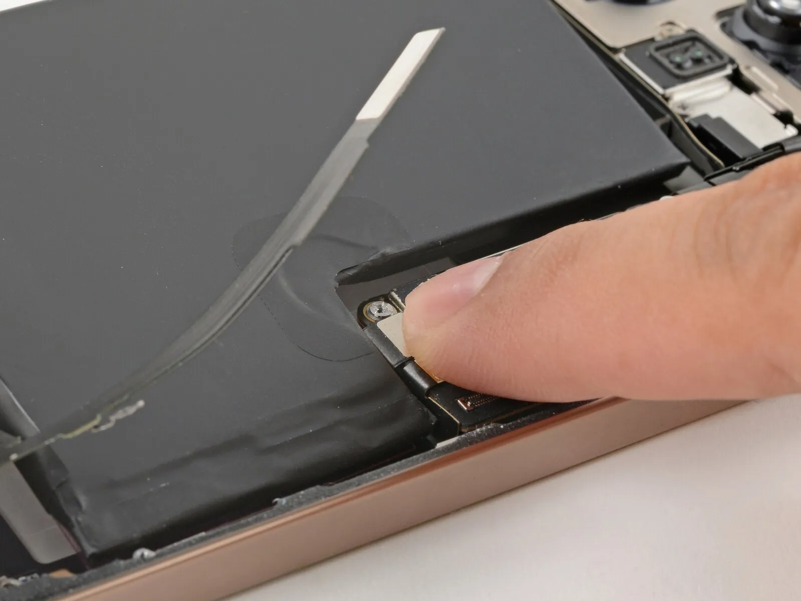
Step 37 | Remove the battery


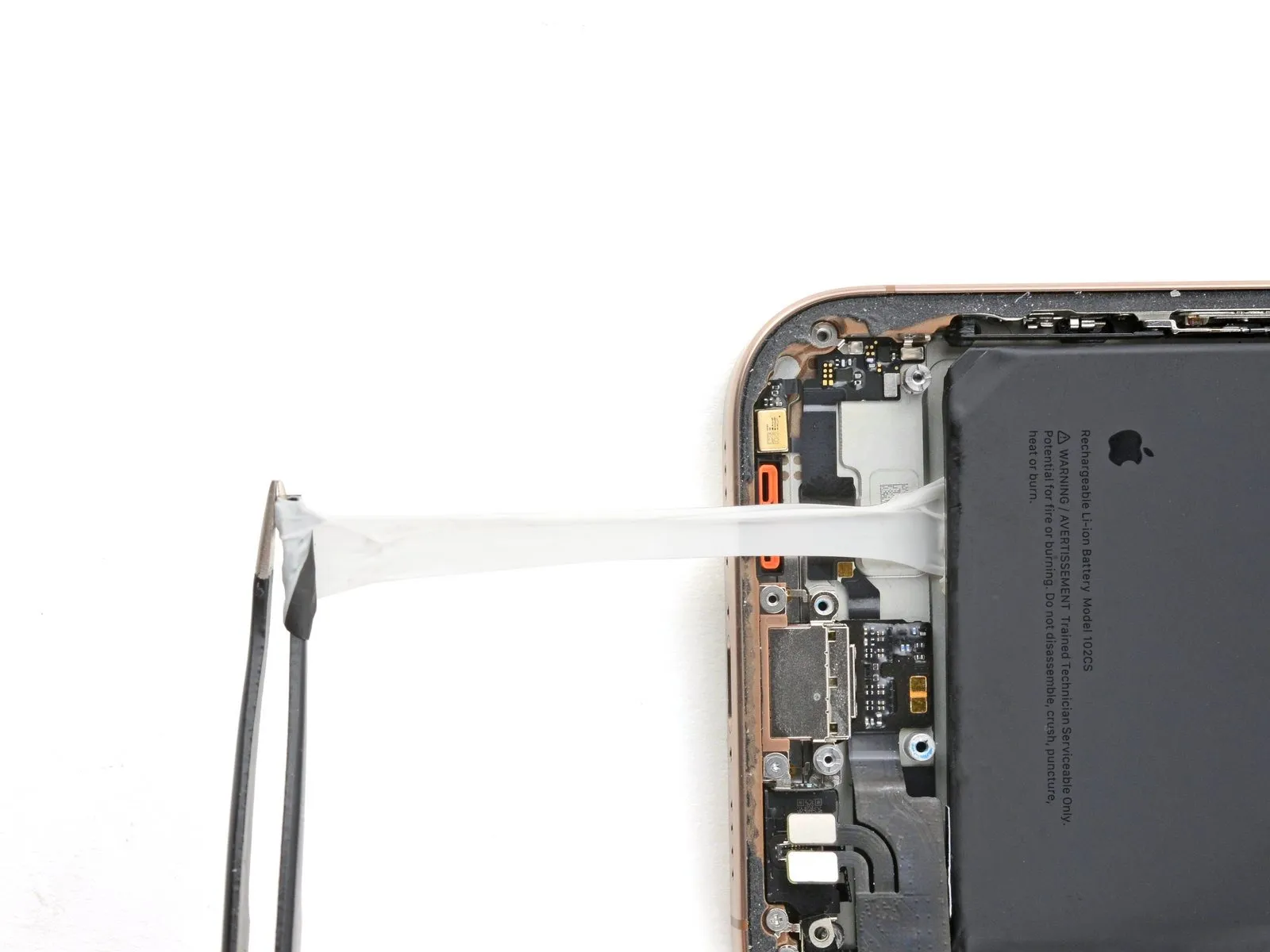
- Carefully insert the pointed end of a prying tool between the battery and the black pull tab located at its base to detach them.
- Carefully lift the tab from the battery's surface using tweezers.
- Wait to extract the retaining tab from beneath the battery.
Step 38
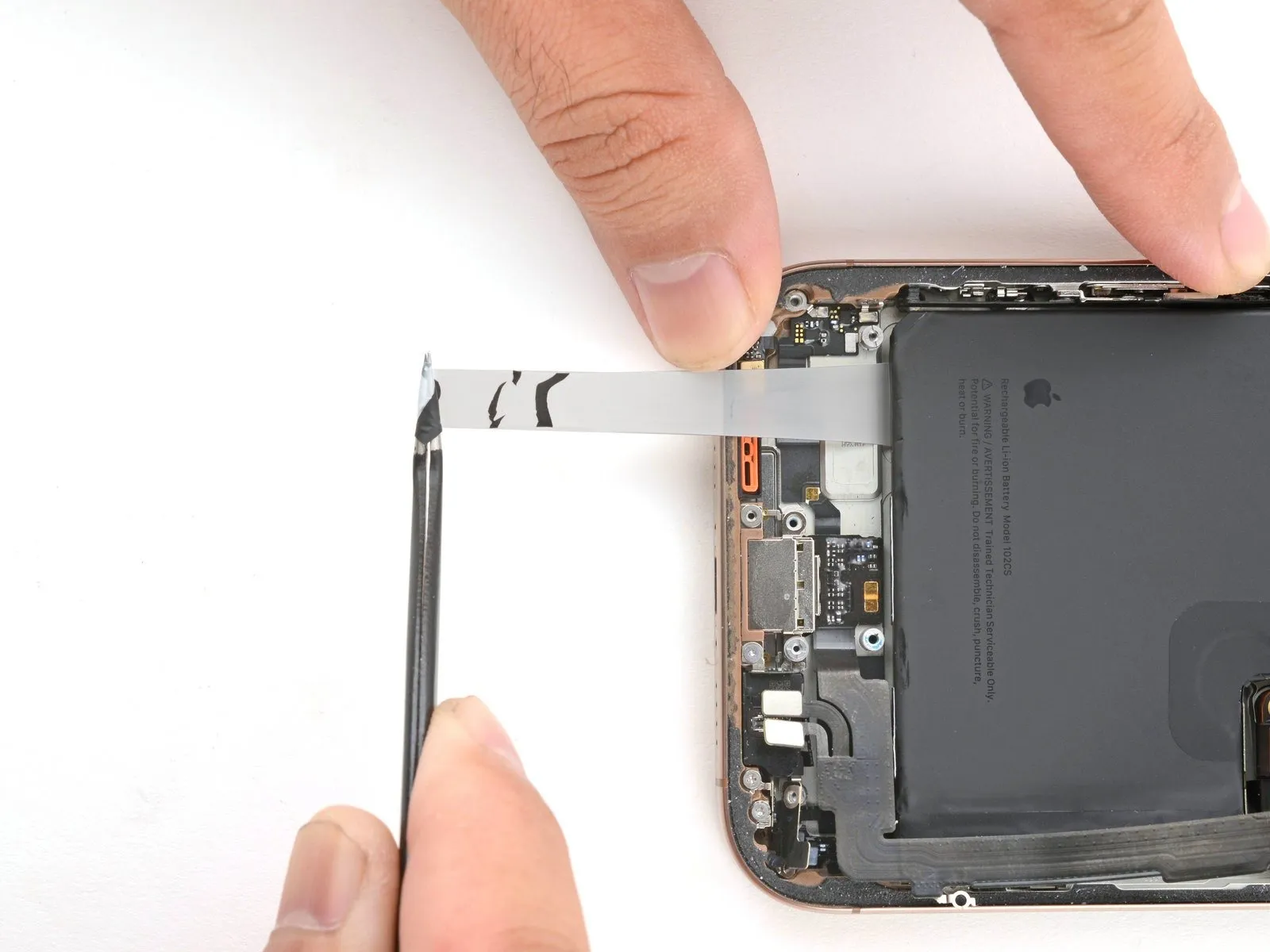

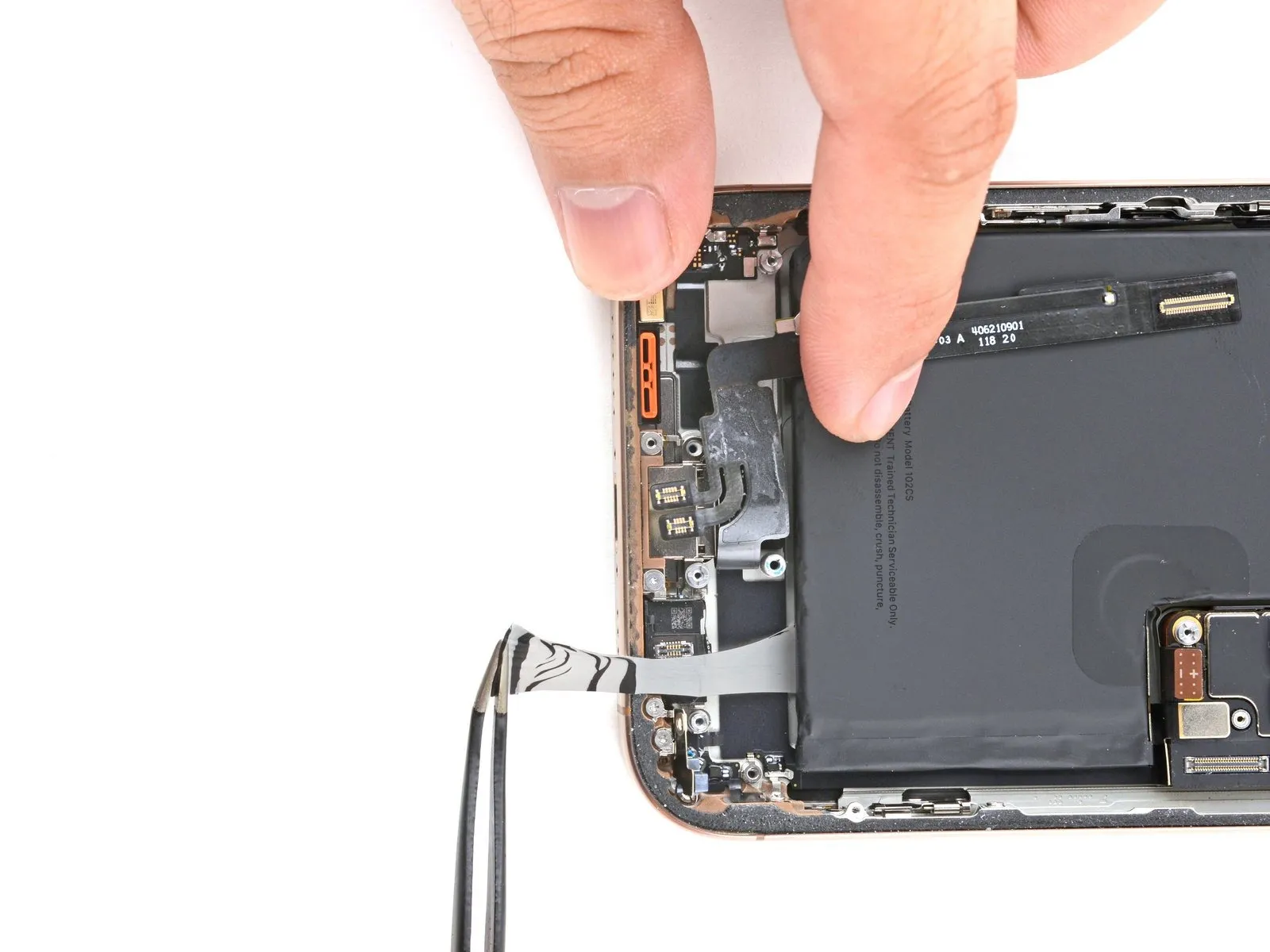
- Grasp the pull tab securely with tweezers or your fingertips.
- Gently separate the battery from its housing by easing the adhesive free, maintaining a shallow angle.
- Allow ample time for the adhesive strip to fully extend, reapplying pressure as needed to ensure proper adhesion. Prevent scraping or pulling the strip across any components or wiring located above the battery.
- To manage excess strip length, fold it around your tweezers and proceed with the removal process.
- Should a strip become detached, attempt to recover it from beneath the battery; if unsuccessful, proceed to the subsequent strip.
Step 39
Apply the same steps again, using the other two adhesive strips.
To reach the adhesive strips, gently maneuver the lower assembly cable, adjusting its position as necessary.
Step 40

Having successfully detached the three stretch release adhesive strips, proceed by disconnecting the battery, then follow the reassembly instructions located three steps further down.
Should any adhesive strips become detached, proceed to the subsequent step for removal using isopropyl alcohol.
Step 41 | Alternate method to remove the battery
- Should the adhesive strips fail, proceed with the following instructions to detach the battery.
- Gently raise the lower portion of the device's frame to achieve the desired tilting angle.
- Carefully dispense using either a pipette or a syringe.Apply a quantity of two to three drops.Carefully apply isopropyl alcohol with a concentration exceeding 90% along the battery's lower edge, positioning the alcohol near the points of separation for each detached adhesive strip.
- Allow 60 seconds for the isopropyl alcohol to saturate the area beneath the battery, facilitating adhesive loosening.
Step 42
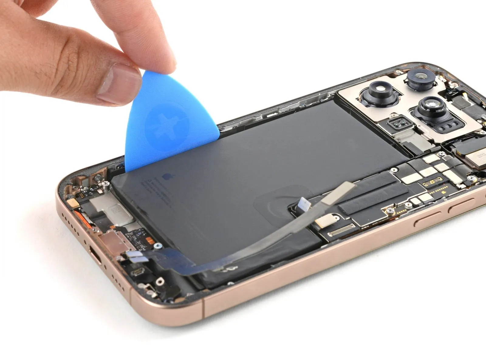
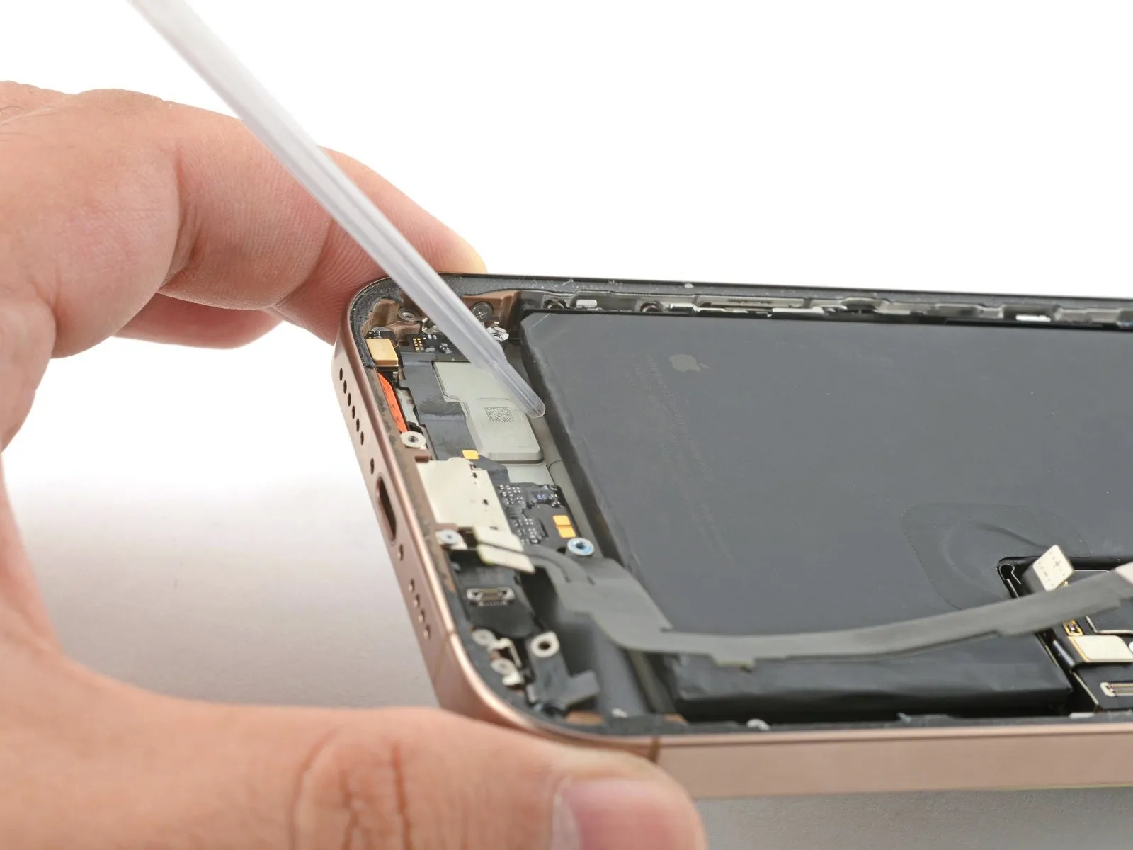
- Using a thin, flat opening pick, gently slide its edge into the gap located on the left side of the battery, where it meets the device frame.
- Apply consistent, gradual upward pressure to dislodge the battery, allowing the adhesive to detach.
- Handle the battery with care to avoid any deformation; if resistance is encountered during removal, carefully add additional isopropyl alcohol to ease separation.
- After the adhesive has weakened, carefully grasp and detach the battery.
Step 43 | Disassembly complete

With the device now disassembled, proceed to the following instructions for reassembly, which detail the process of putting your iPhone back together.
Visual differences in the repair illustrations might occur based on your specific iPhone version, but the steps remain accurate for all models.
Step 44 | Install the replacement battery
- Thoroughly clean the battery compartment, eliminating all traces of adhesive residue.
- Using a clean, non-shedding cloth dampened with a small amount of isopropyl alcohol, carefully clean the frame's exterior.
Step 45

- Carefully remove the protective covering.Carefully remove the adhesive backing from the battery.
- To secure a battery lacking pre-applied adhesive, adhere to the subsequent instructions.Apply fresh adhesive strips designed for stretch release.Alternatively, affix it using adhesive double-sided tape.
Step 46

- Due to the strong adhesive on the battery, exercise caution during placement within its designated area; once contact is made, repositioning is impossible.
- Carefully position the battery so that it is partially inserted into its designated compartment.
- Carefully position the battery within the designated compartment.
Step 47

- Apply consistent, even pressure to the battery surface with your hands, maintaining contact for a full ten-second duration to ensure proper adhesion to the frame.
- To prevent electrical damage, detach the battery connector from the logic board.
Step 48 | Install the loudspeaker
- Position the lower edge of the loudspeaker so it forms an angle with the frame.
- Carefully insert the loudspeaker into its designated cavity.
Step 49
- Using a Phillips head screwdriver, fasten the loudspeaker to its housing with the four screws provided.
Begin the process with a single unit.One point seven millimeters.Use a Phillips screwdriver to remove the extended screw.
Begin the process with a single unit.A measurement of one and one-half millimeters.Use a Phillips screwdriver to remove the screw, which is long.
Begin the process with a single unit.The specified dimension is four point one millimeters.Use the provided long standoff screw.
Begin the process with a single unit.One point three millimeters.Employ a tri-point screwdriver, type Y000, to manipulate the extended screw.
Step 50 | Install the Taptic Engine
Step 51

Step 52
Step 53
Step 54
- Using a Phillips head screwdriver, fasten the lower assembly cable with the provided screws.
A tri-point screw, type Y000, with a length of 1.0 mm is required.
A Phillips screw, measuring 1.3 millimeters in length, is required.
Step 55
Step 56
- Position the Taptic Engine cover, ensuring the screw holes are properly aligned.
Verify that the cover's lower border securely engages with the frame.
Step 57
- Employ a 3/8-inch socket wrench to loosen the fastener, ensuring you apply consistent pressure to avoid damaging the retaining clip and observe the torque specification of 15 Nm as indicated in the service manual, and be aware that improper handling may result in component breakage.Use a Phillips-head screwdriver.Using the Phillips head screwdriver, fasten the Taptic Engine cover in place with the three screws.
- Begin the process by executing step one.A screw measuring 2.9 millimeters in length.
- Begin the process with the number one.A screw measuring 1.3 millimeters in length.
- Begin the process by executing the singular action.A screw measuring 2.4 millimeters in length.
Step 58
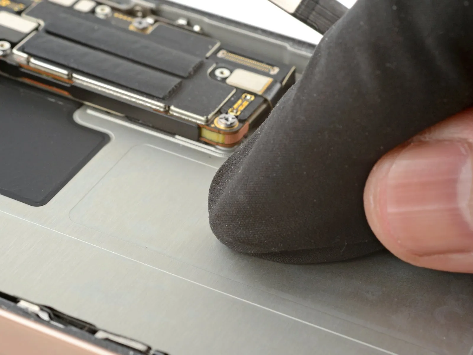
- Carefully align the assembly cable connector and then secure it to the logic board by applying even pressure with a finger or spudger.
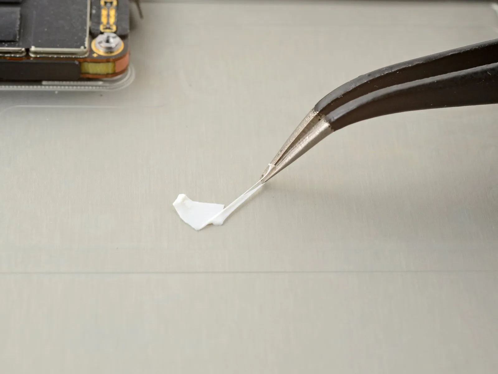
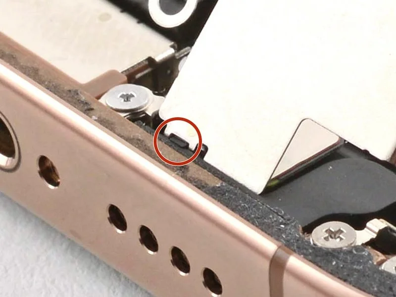
Step 59 | Remove the leftover adhesive


- Carefully avoid damaging the delicate grounding clips during frame cleaning; if one becomes displaced, restore it to its original position using your fingers or tweezers, applying gentle pressure.
Carefully detach sizable adhesive remnants from the frame's edges, employing either blunt-nosed tweezers or direct finger manipulation.
Carefully remove adhesive remnants from the frame's surface using a spudger.
To loosen a firmly bonded adhesive, direct warm air from a hair dryer or heat gun onto the area and repeat the process.
Step 60 | Clean the back glass


- To facilitate proper adhesion when reinstalling the rear glass, use a microfiber or lint-free cloth lightly dampened with a small quantity of isopropyl alcohol having a concentration greater than 90%, and clean the glass's edges.
Step 61 | Clean the frame

- To protect the surface, cover the tip of a screwdriver with either a clean, lint-free cloth or a coffee filter.Use a plastic pry tool to gently separate.Use a small amount of isopropyl alcohol with a concentration exceeding 90% to moisten the area.
- Carefully remove adhesive residue by wiping along the frame's edge in a single direction; thoroughness at this stage is important because a clean surface enables the new adhesive to spread uniformly, which is essential for a strong, reliable bond.
Step 62 | Apply the replacement adhesive

- To ensure correct placement, position the adhesive sheet onto the frame, aligning it with key features like the camera opening and the notches located on the upper and lower borders.
Step 63


- Carefully lift the corner tab of the adhesive backing, then slowly remove the liner to reveal approximately one-third of the adhesive surface.Use a bonding agent..
- Because the adhesive surface is highly adhesive, avoid contact with other materials until you intend to bond it to the frame.
- Carefully remove the protective backing layers from the adhesive until only the surface intended to bond with the frame is visible.
Step 64


- Ensure the visible perimeter is precisely positioned.Double-sided tapeCarefully align the adhesive with the iPhone's frame edge; after application, repositioning is impossible and requires replacement of the adhesive strip.
- Ensure proper positioning, then apply light pressure to the visibleDouble-sided tapeSecure the component to the frame.
Step 65


- Carefully remove the backing material from the adhesive, ensuring firm contact with the surface as you apply it.
- Proper adhesive placement ensures the borders seat flush and precisely.
- Carefully reposition any slight adhesive misalignment by gently drawing the extended edges toward the frame.
- Should the adhesive develop creases or wrinkles, discard the affected material and reapply a new portion of adhesive.
- Should replacement adhesive strips be unavailable, the iPhone can be reassembled and used as normal without them; however, be aware that the device's water resistance will be reduced until a new adhesive set is installed.
Step 66


- Carefully apply pressure along the device's outer edges with a spudger to release the adhesive securing it.
- Handle the delicate grounding clips with caution; should they become displaced, restore them to their original position using your fingers or tweezers, applying gentle pressure.
- Apply gentle pressure to avoid distorting or overextending the adhesive.
Step 67


- Carefully detach the large front liner by gently prying up the pull tab, typically located at a corner, using a spudger or your fingertips.
- Carefully separate the extensive adhesive backing from the component using the provided pull tab.
- To avoid unintended adhesion during reassembly, a protective liner might still be in place around the edges; postpone its removal for now.
Step 68 | Connect the back glass

Using a repair tool, gently support the rear glass panel on its right side to prevent movement.
Step 69

Step 70 | Connect the battery

- Carefully align the battery press connector and secure it to the logic board by applying even pressure with a finger or spudger.
To troubleshoot a non-responsive iPhone, establish a connection to a power outlet and attempt powering it on.
After logic board replacement, a non-functional display necessitates following the screen guide's instructions to establish a direct connection to the display connector.
Step 71 | Install the connector covers

Step 72
- Employ a Y000 tri-point screwdriver to fasten the four screws that hold the back glass connector cover in place.
- Two.One point three millimeters.Utilize screws of a substantial length.
- Two.One millimeter.Utilize screws of extended length.
Step 73

Step 74
- Employ a 3/8-inch socket wrench to loosen the retaining bolt, ensuring you maintain a firm grip and wear safety glasses to protect against potential debris; subsequently, carefully detach the component.Use a Y000-sized tri-point screwdriver.Using a Phillips head screwdriver, fasten the battery connector cover in place with the three screws provided.
- Two.Screws, each measuring 1.3 millimeters in length, are required.
- Begin the process by executing the singular action.A screw measuring 1.0 millimeters in length.
Step 75 | Remove the final adhesive liners


- Carefully separate the surrounding liners with your fingers or a spudger to reveal the underlying adhesive.
To prevent adhesive contamination, avoid any contact with the adhesive surface once the liners are removed.
Carefully inspect both the frame and rear glass, ensuring all liners have been completely removed; confirm the absence of any remaining liners.
Step 76 | Install the back glass


- Align the upper edge of the rear glass with the frame and gently position the entire component.
Should you encounter difficulty during movement, inspect the perimeter clips, as one might be deformed and obstructed by the frame. Carefully realign any clips that appear bent at the location of the resistance.
Apply even pressure to the perimeter of the rear glass to ensure it makes full contact with the device's frame.
Step 77 | Apply heat to the perimeter

- Employ a 5/32-inch Allen wrench to tighten the retaining screw to a torque of 6-8 inch-pounds, ensuring the component is securely fastened and preventing damage due to excessive force.Utilize a device designed to emit warm, directed airflow, typically employing a heating element and fan, to dry hair; ensure the appliance's wattage is appropriate for the intended application and observe all safety precautions outlined in the manufacturer's documentation.,Apply warmth using a device that generates heat, ensuring the temperature remains consistent and does not exceed 200°F (93°C) to avoid damaging surrounding components.Using appropriate safety precautions, ensure the specified component is either a or anUse a specialized tool designed for electronics repair, such as an iOpener.Carefully apply heat to the back glass edges until the surface temperature is high enough to be uncomfortable to the touch.
Applying warmth loosens the adhesive, facilitating a stronger connection.
Step 78 | Apply pressure to the perimeter


- Apply consistent, even pressure with your hands along the entire edge.Using appropriate safety precautions, carefully manipulate the device to access the internal components, noting that the iPhone is a complex assembly requiring meticulous handling and specialized tools..
Step 79


- Position theUsing appropriate safety precautions and tools, carefully handle the device, referred to as an iPhone.Position the device with the display facing downward on a level, non-abrasive surface.
Apply a length of tape along the edges of the rear glass to shield the surface from scratches.
Using coins, build a circular barrier along the back glass's edge, raising it to the same height as the rear camera lenses.
To ensure proper adhesion, secure the device's edges with vise clamps.
Step 80


- Use between three and four substantial weights to secure the component.Refer to the documentation for detailed specifications regarding the printed materials.Position directly atop.Carefully handle the device, referred to as an iPhone..
To prevent potential marking, avoid placing valuable items beneath the book cover during this process.
Allow the books to remain positioned atop the device for approximately half an hour.
Applying force will engage the adhesive properties.
Step 81 | Install the pentalobe screws
- Employ a driver specifically designed for P2 pentalobe screws.Secure the pair using the specified fasteners.Screws measuring 7.4 millimeters in length.Flanking the charging port are two locations.