iPhone 16 Pro Max Screen Replacement
This document details the procedure for substituting a malfunctioning, fractured, or unresponsiveCarefully detach the display panel, noting that it is secured with adhesive and requires gentle manipulation to avoid damage, and ensure proper alignment during reinstallation to maintain touch functionality.Using a 5/32-inch hex key, carefully tighten the retaining screw to a torque of 6 in-lbs, ensuring you do not overtighten and damage the threads.iPhone 16 Pro Max.
To proceed, obtain a substituteSecure the display assembly with adhesive specifically designed for screen applications.Ensure all preceding steps have been executed and all necessary components are reassembled correctly.
- Carefully observe that the specified torque of 25 Nm must be applied when tightening the M6 bolt using a torque wrench.To avoid short circuits, exercise extreme caution and refrain from utilizing metal tools for separation or contacting any bare electrical connections while this procedure is performed, as battery disconnection is not possible.Using appropriate safety precautions, carefully manipulate the device to access the internal components, noting that the iPhone is a complex assembly requiring meticulous handling..
To ensure proper functionality following the repair, perform calibration using genuine Apple components.Carefully detach the display panel, ensuring all retaining screws—typically five Phillips head screws—are removed and noting their locations for reassembly, then gently separate the screen from the device casing, being mindful of the flexible display cable connecting it and avoiding any undue stress that could cause damage.Employ the Repair Assistant application to proceed.
Step 1 | Before you begin
To mitigate safety risks associated with charged lithium-ion batteries, ensure your iPhone's battery level drops to less than 25% before proceeding.
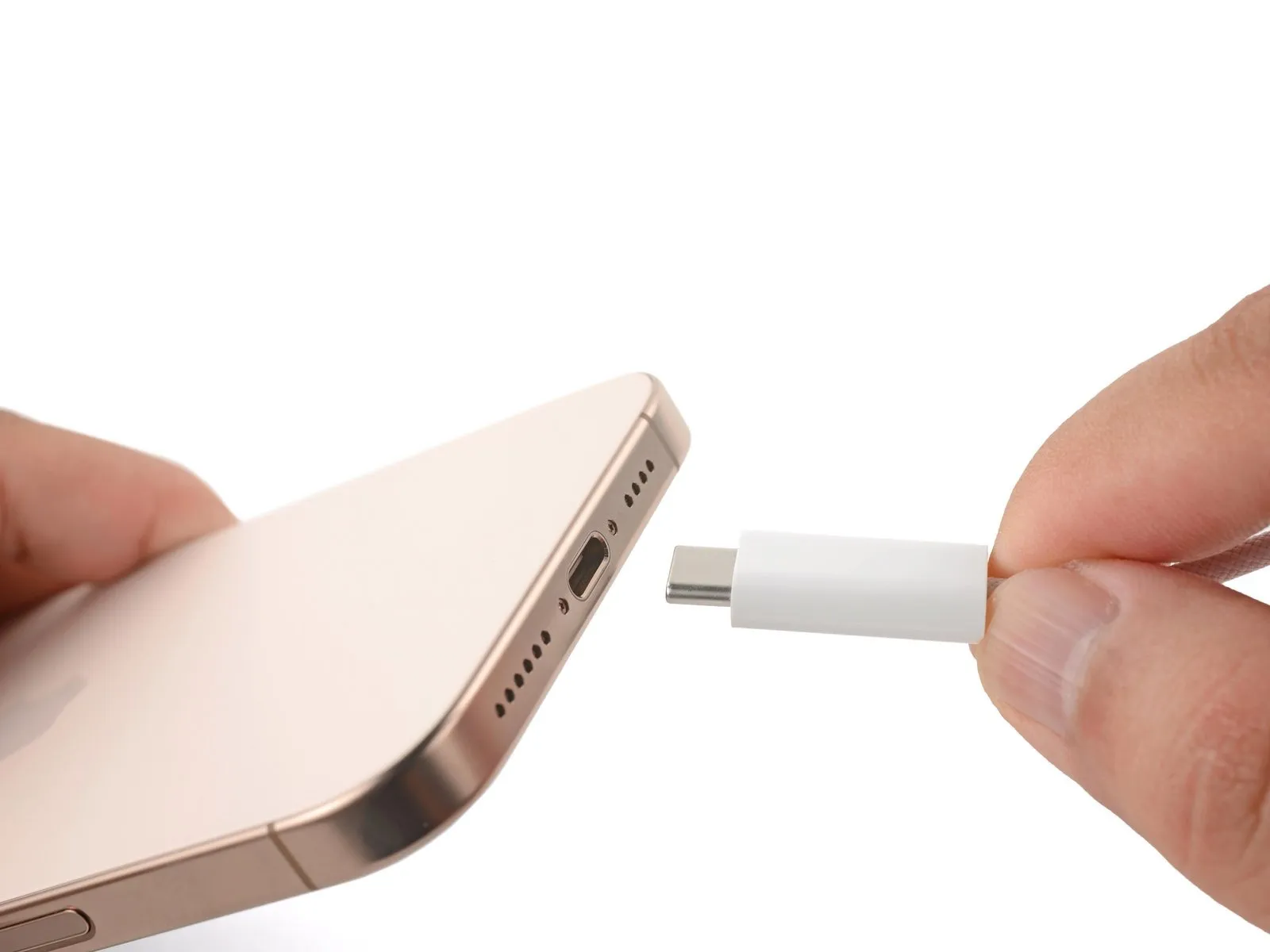
- Disconnect all connected cables from the iPhone.
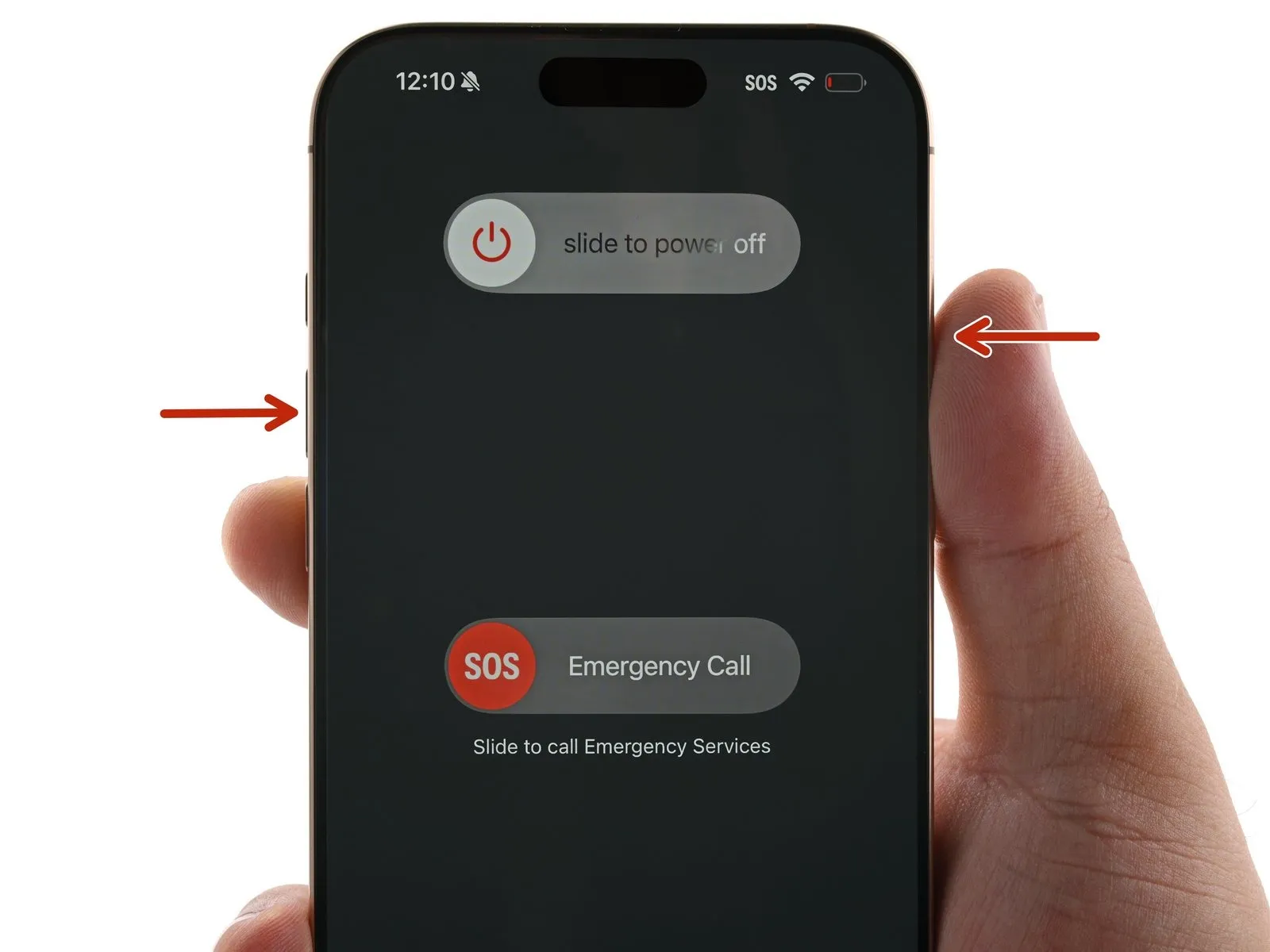
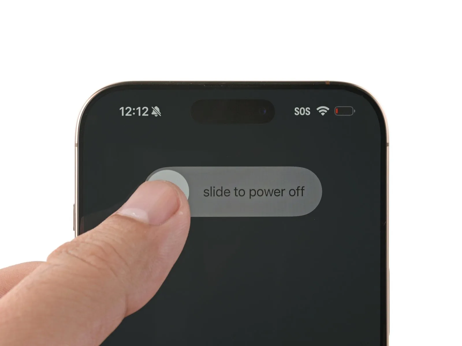
- Simultaneously press and maintain the power button and one of the volume buttons, then slide your finger to deactivate the iPhone.
Step 2 | Tape over any cracks
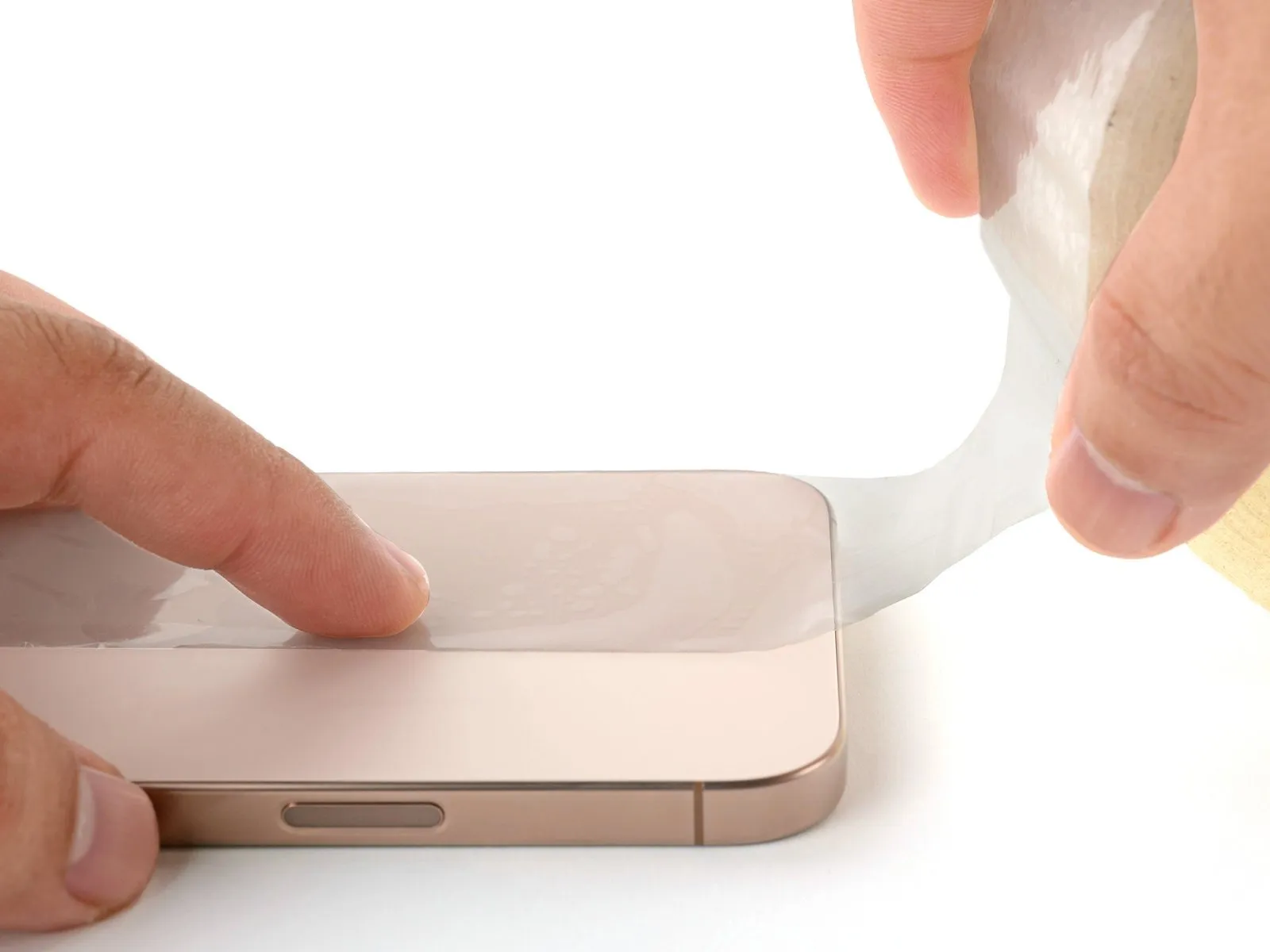
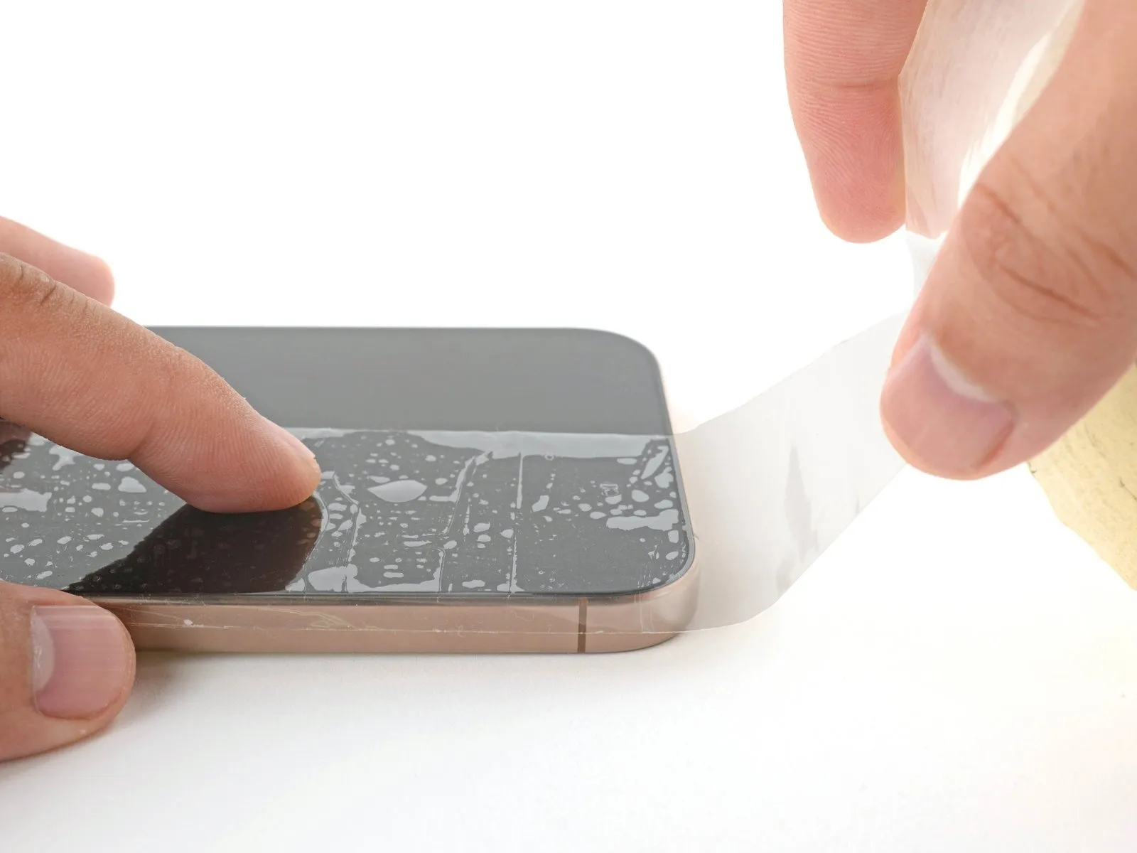
To prevent injury and simplify the repair process when the display or rear glass exhibits severe cracking, apply multiple layers of packing tape, ensuring they overlap, across the damaged areas.
Ensure a flat surface, approximately the size needed for suction cup adhesion, exists close to the lower perimeter.
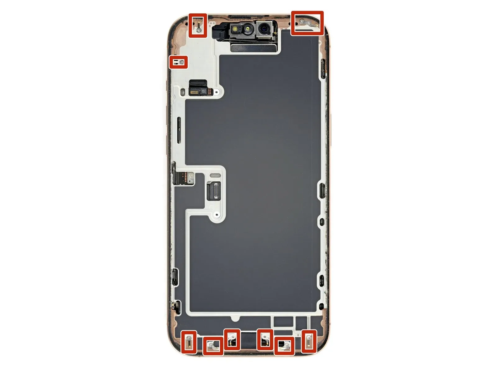
Step 3 | Remove the pentalobe screws
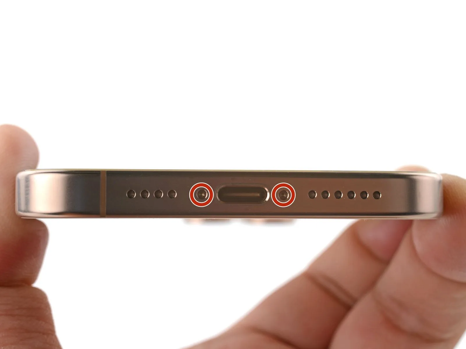

Employ a 5/32-inch hex key to tighten the retaining screw to a torque of 6-8 inch-pounds, ensuring that excessive force is avoided to prevent damage to the threads.Use a P2 driver with a pentalobe tip.Using the appropriate screwdriver, detach the two screws, each measuring 7.4 mm in length, located on both sides of the charge port.
Step 4 | Mark your opening picks


Before proceeding, be aware that potential hazards exist; observe all safety precautions to prevent injury.Excessive insertion of the opening pick may result in device damage.
- Determine the dimension using an appropriate measuring tool.Three millimeters.Using a permanent marker, indicate the opening's position on the tip.
- Alternative corner markings, using the same measurement values, are permissible.
- Securely affix a coin to the tip of a pick using adhesive tape.Three millimeters.Beginning at the very end, proceed from that point.
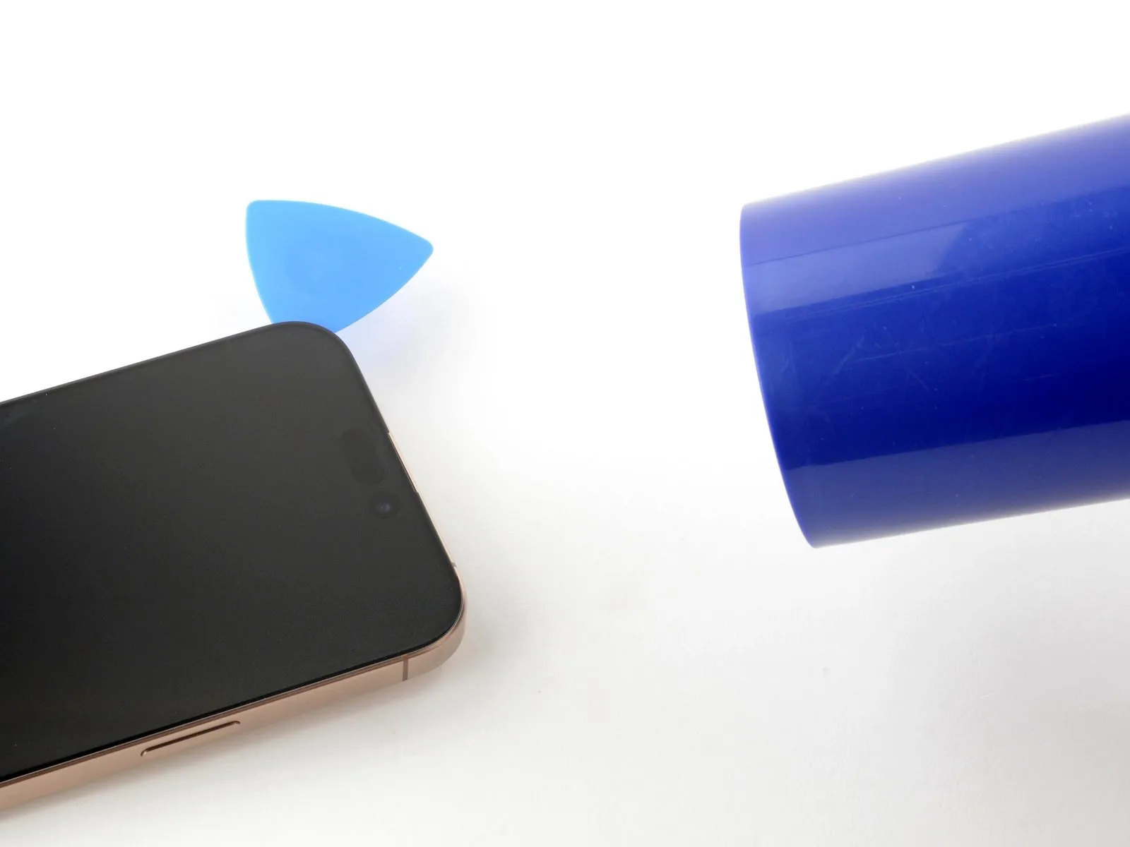
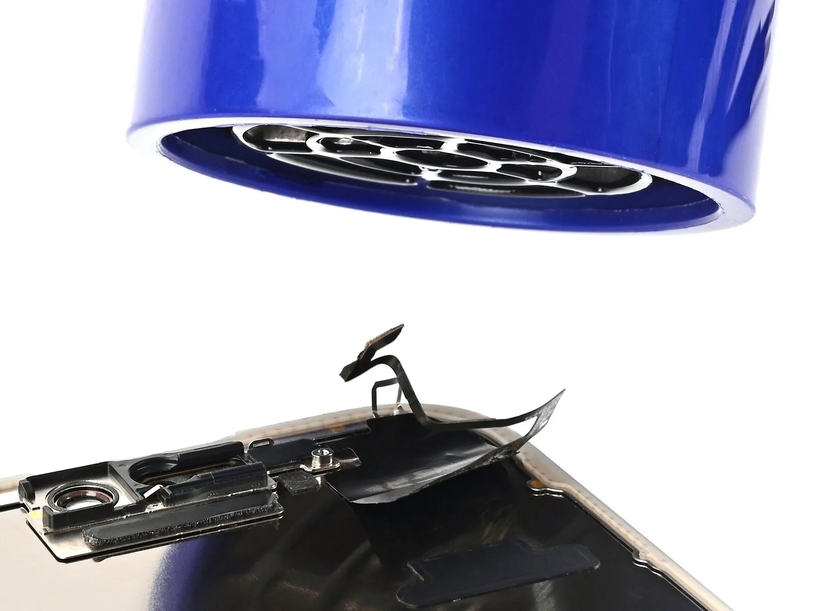
Step 5 | Create a gap with a suction handle
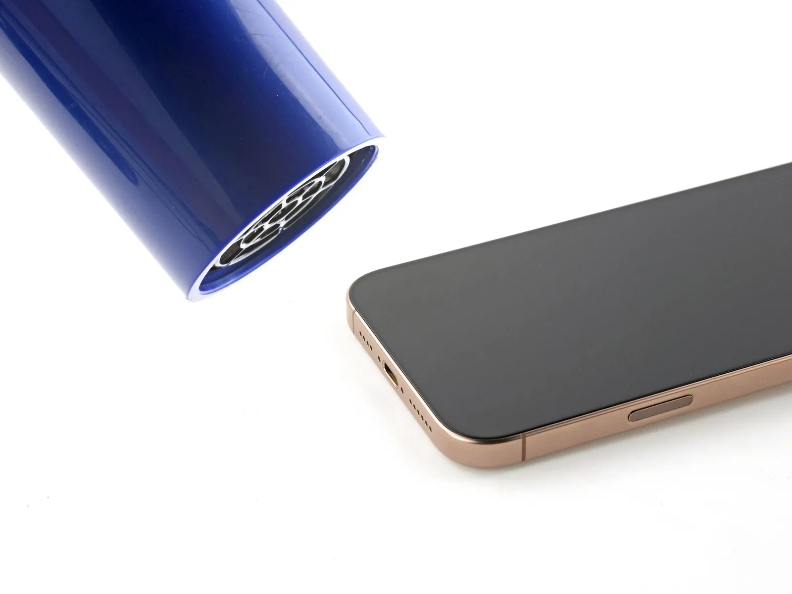
- Apply heat evenly along the screen's lower border with a hair dryer or heat gun, ensuring the surface reaches a temperature that is noticeably warm when touched.
- Alternatively, an iOpener can be employed to warm the display; ensure correct application and heating by adhering to the subsequent procedure.
Step 6


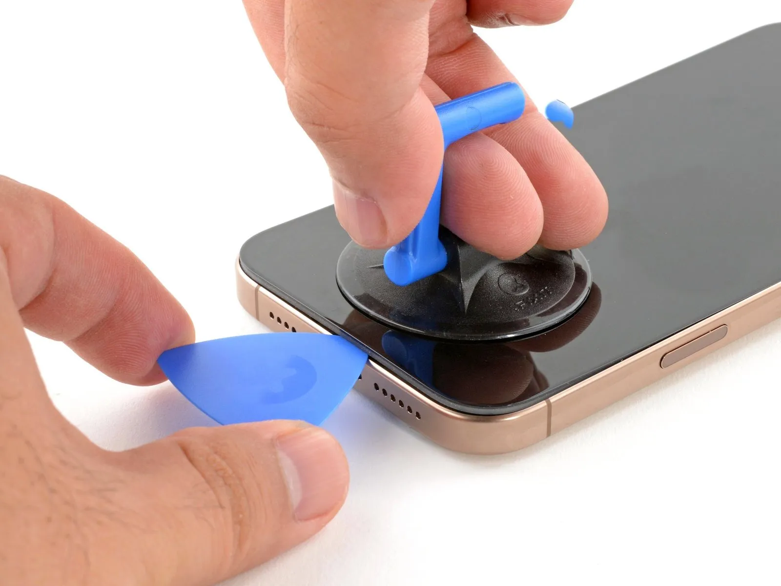
- Using a suction handle, carefully secure the lower edge of the screen.
- Using one hand to stabilize the frame, apply a firm, consistent upward pull to the handle, generating a separation between the screen and the frame.
- Increase the heat applied to the edge and repeat the separation attempt if a gap doesn't form.
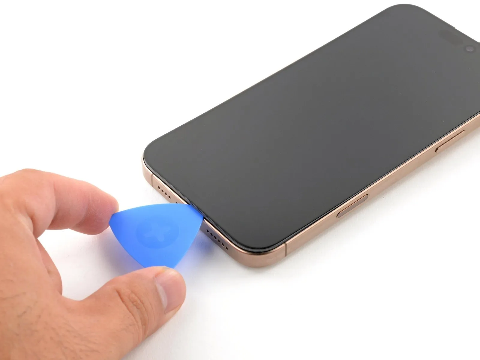
- Carefully slide the pointed end of a prying tool into the separation.
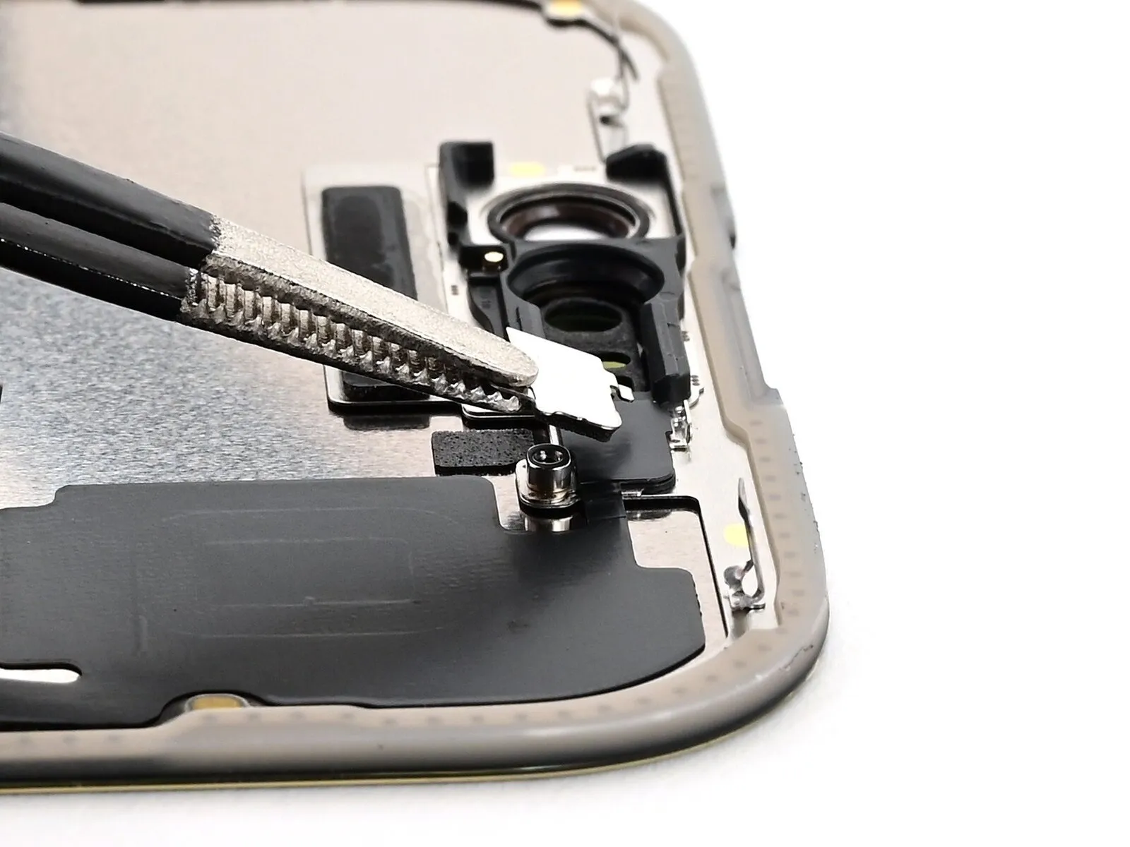
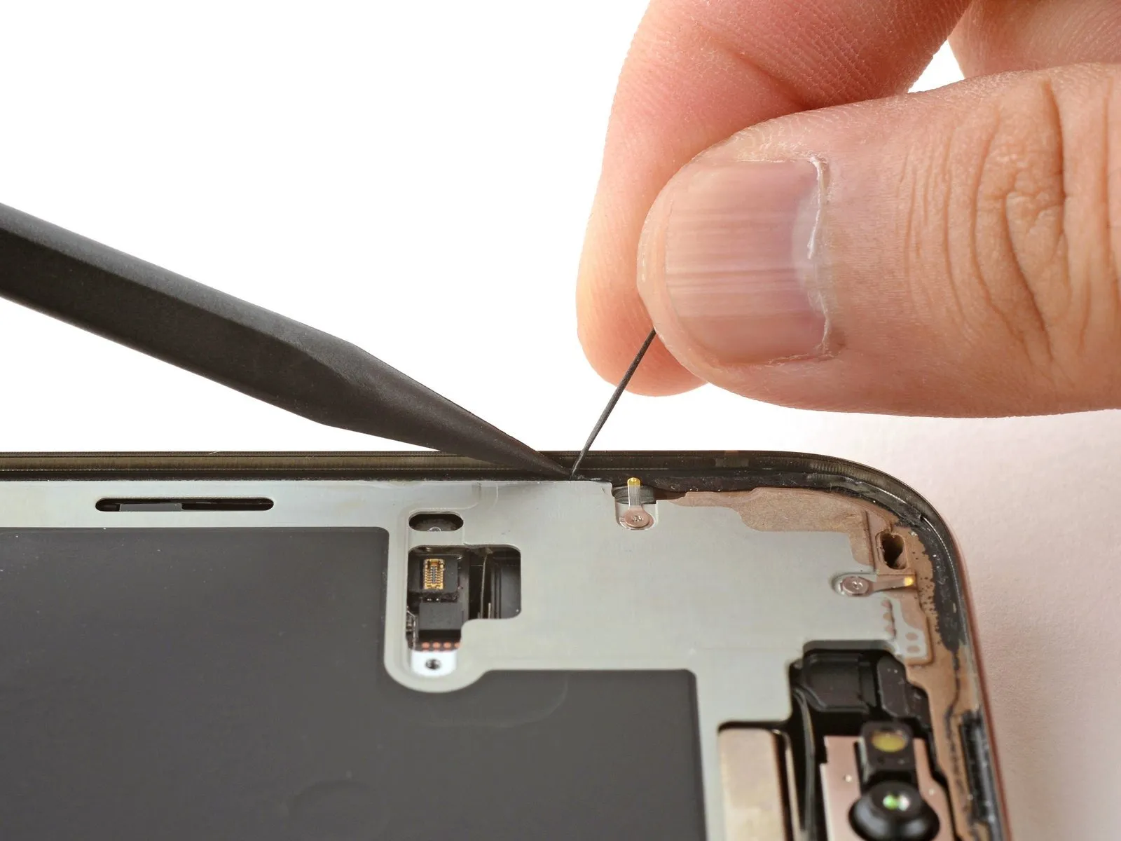
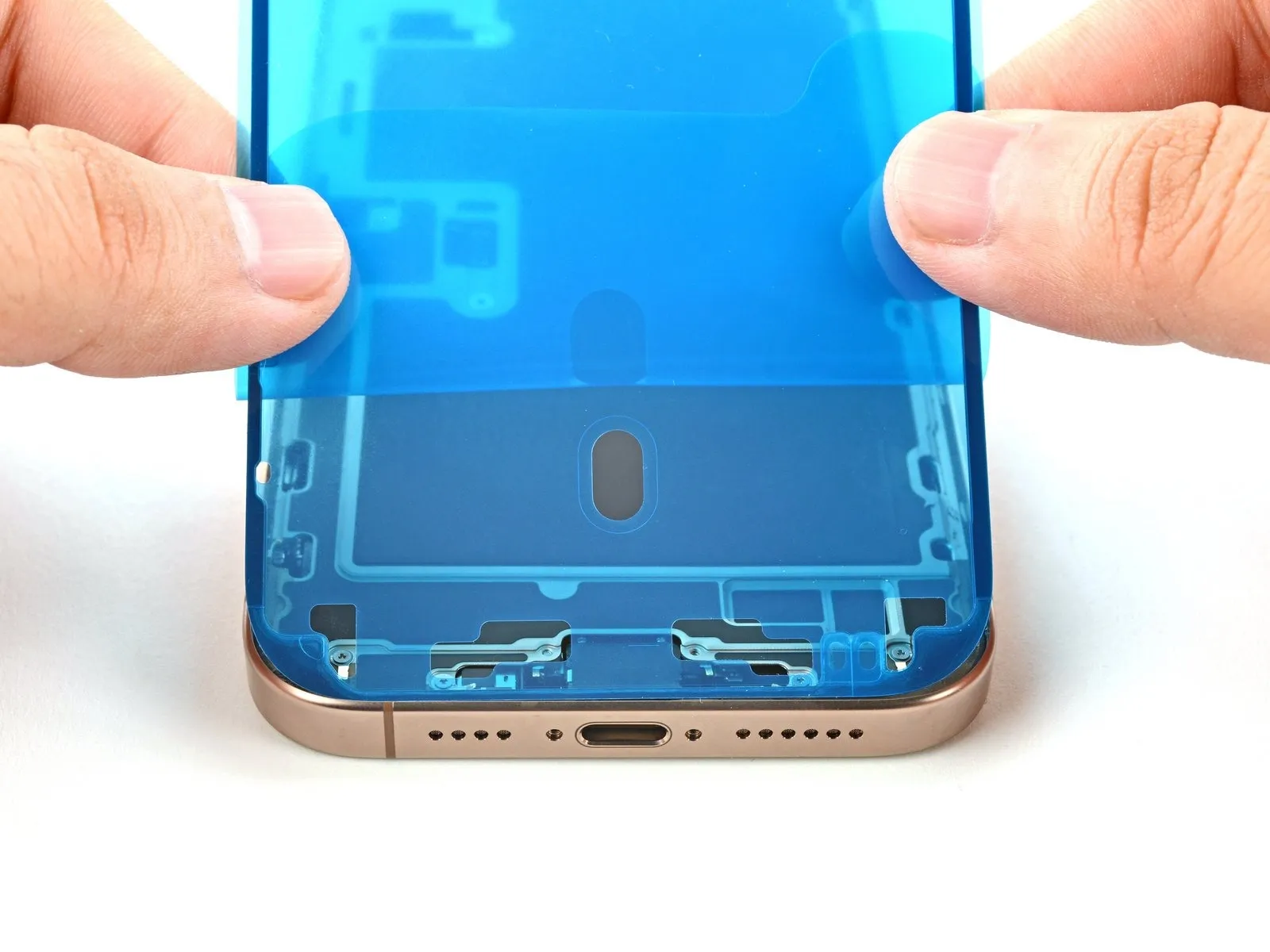
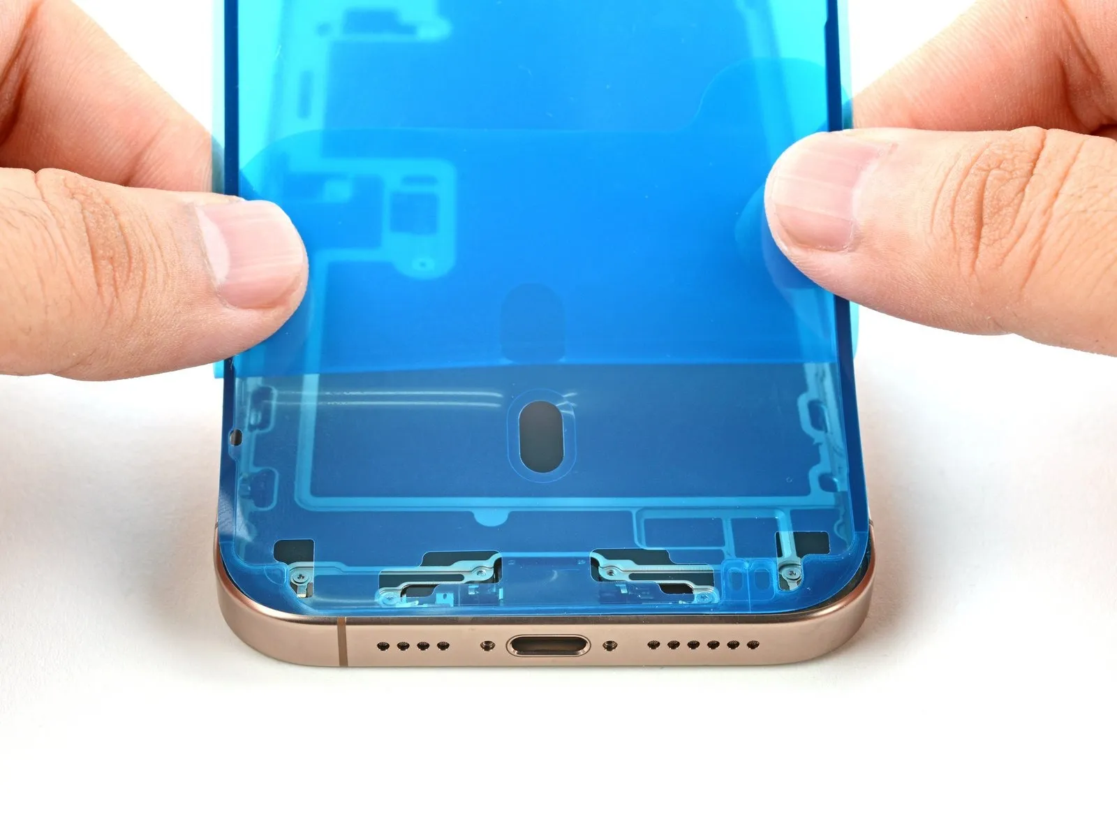
Step 7 | Screen information

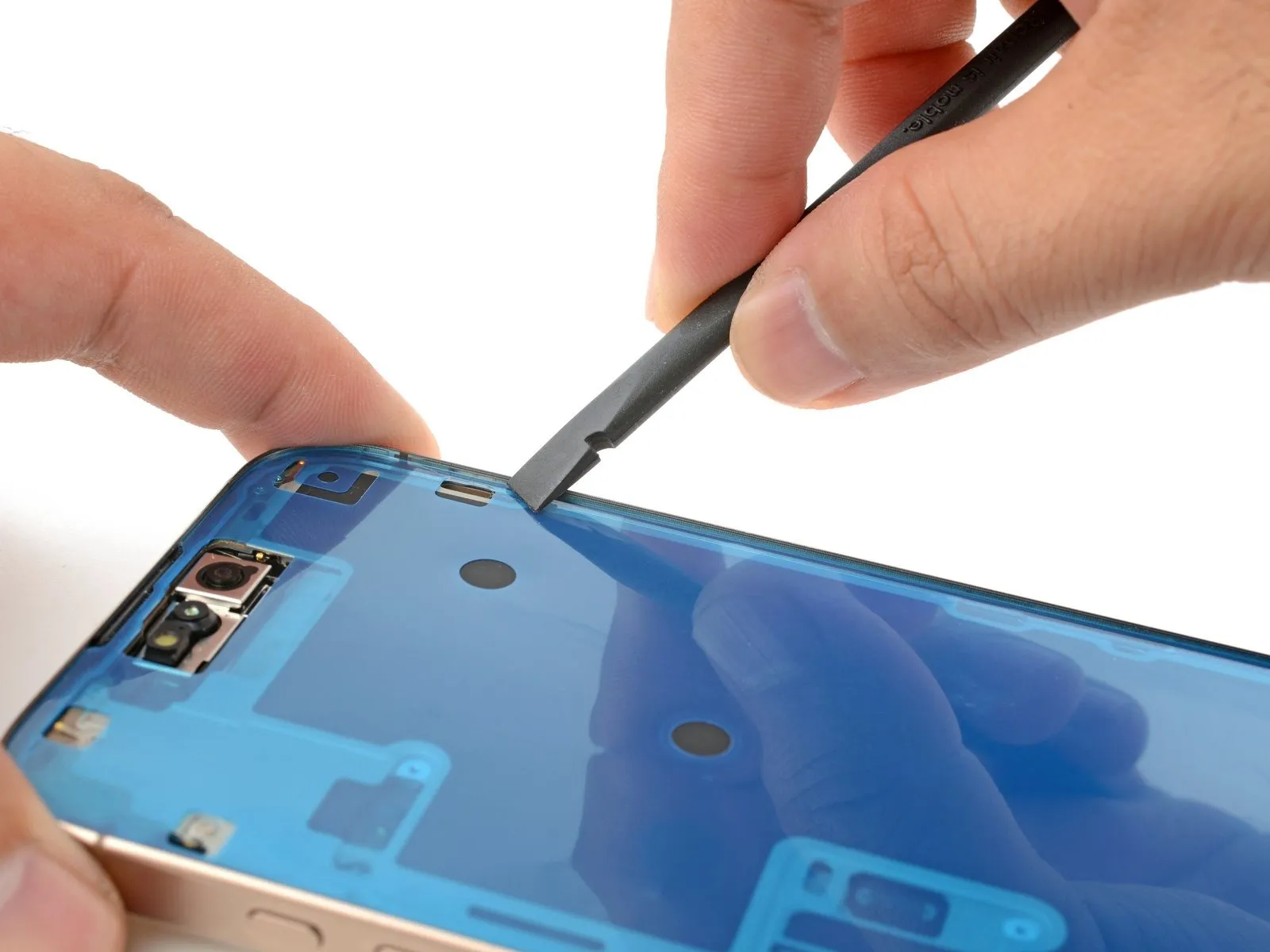
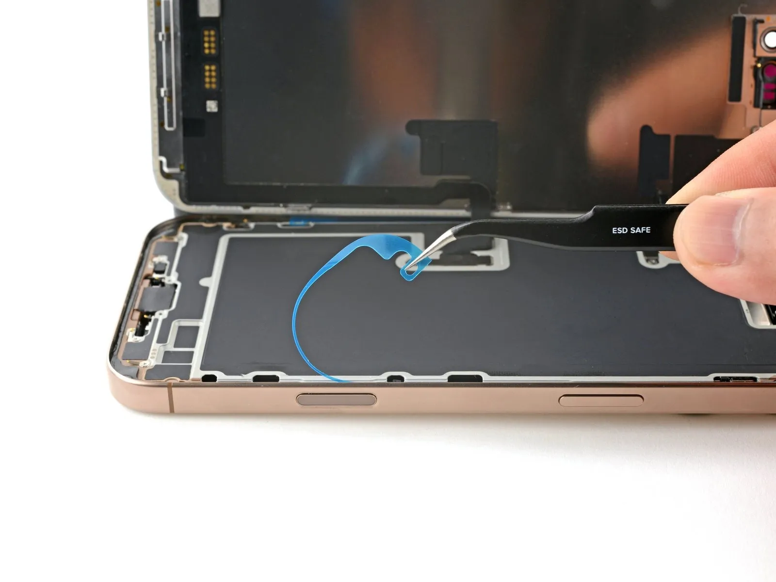
- To prevent damage to surrounding components, limit the depth of your tool insertion to a maximum of 3 mm when separating the screen from its adhesive during the subsequent steps.
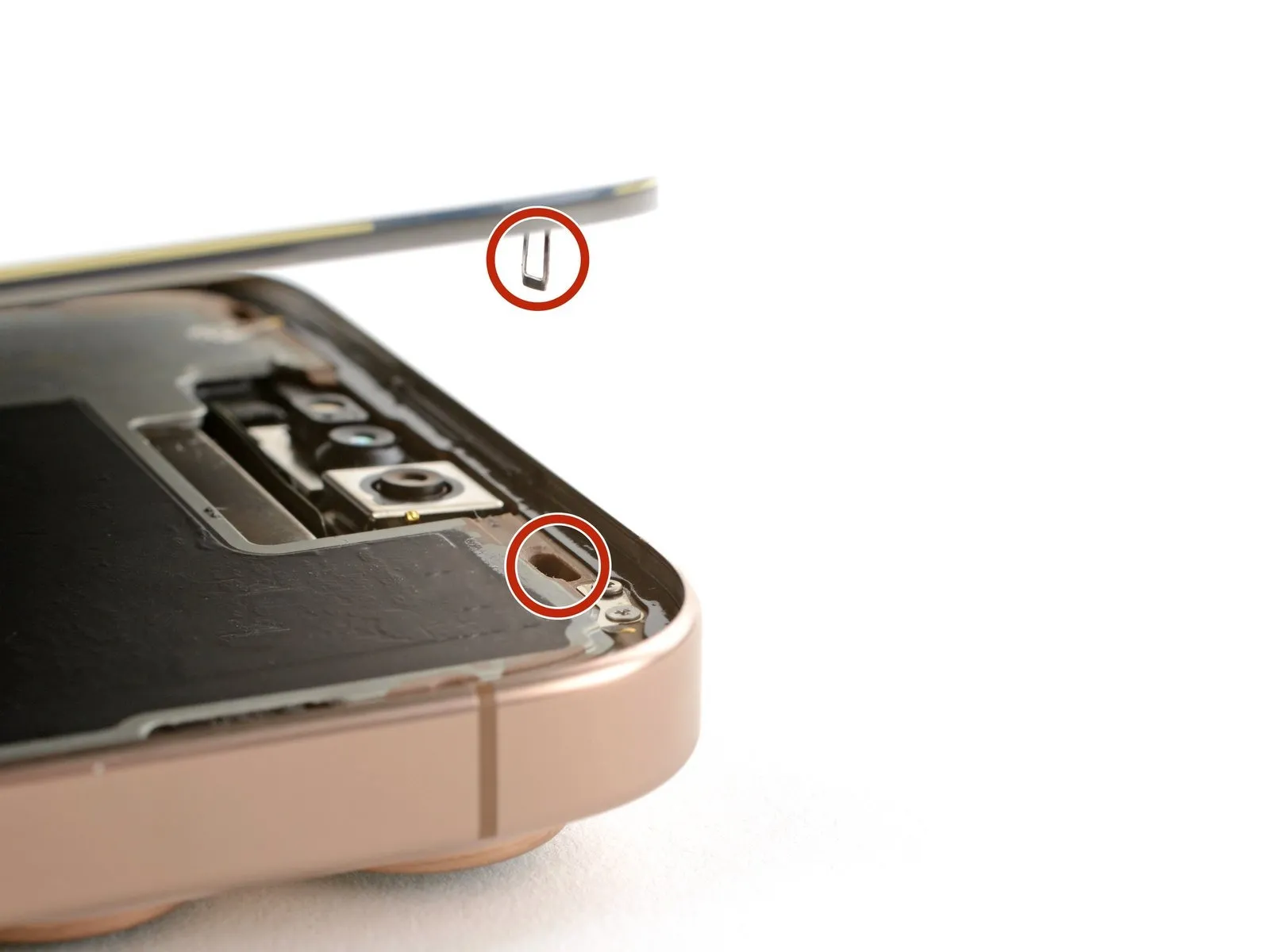
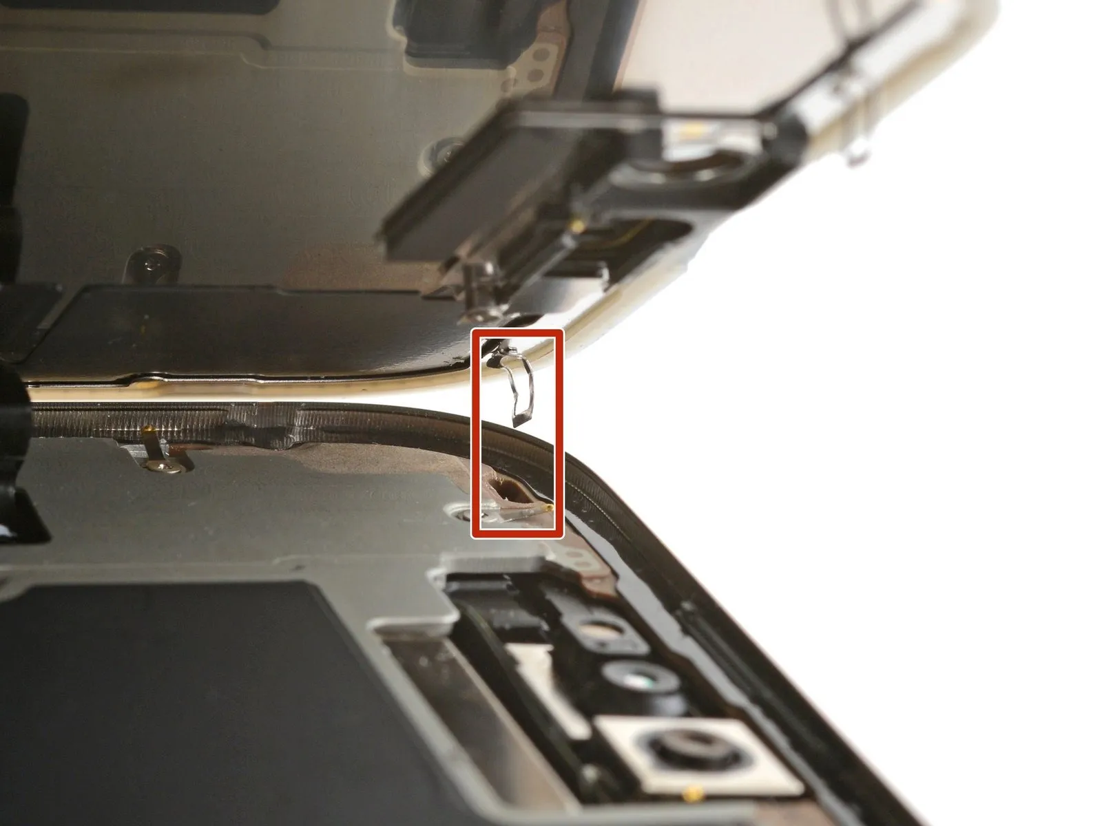
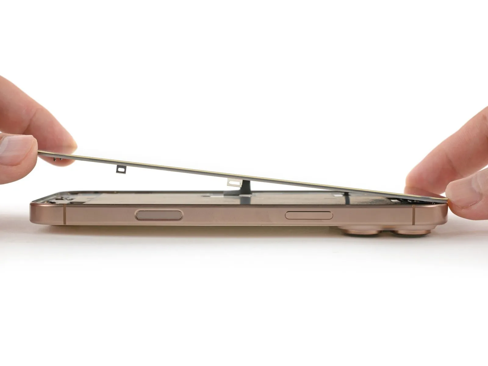
- Two thin wires, essential for the screen's function, attach to the iPhone: one is located directly over the Action button, and the other is positioned approximately midway down the left side.
- The iPhone incorporates several spring-loaded electrical contacts arranged circumferentially.
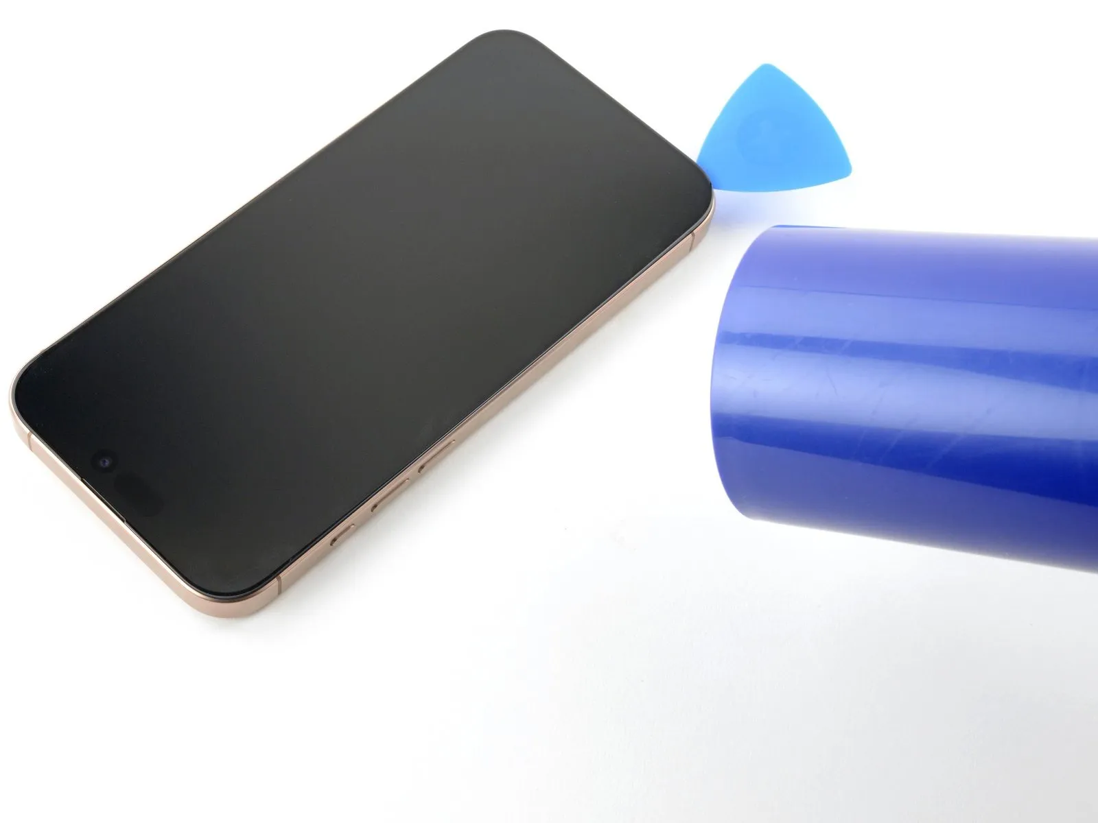
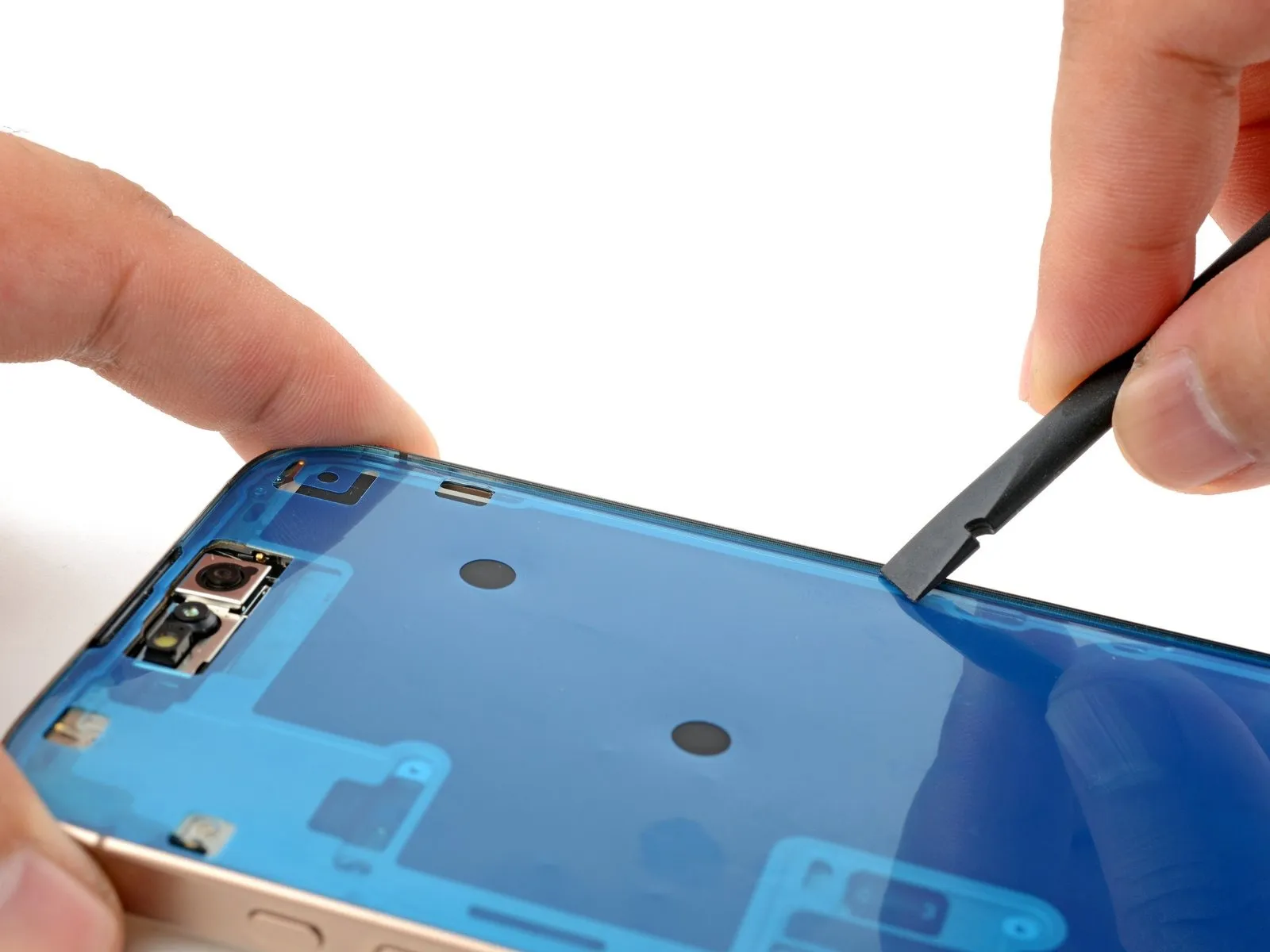
Step 8 | Slice the bottom edge adhesive

- Using the opening pick, carefully separate the adhesive bond by gently working it along the lower perimeter.
- To prevent spring contact damage, limit pick insertion depth to a maximum of 3 millimeters.
- To ease cutting, apply heat to the adhesive edge for one minute.
- Maintain a gap in the lower left corner using the provided pick to stop the adhesive from bonding shut.
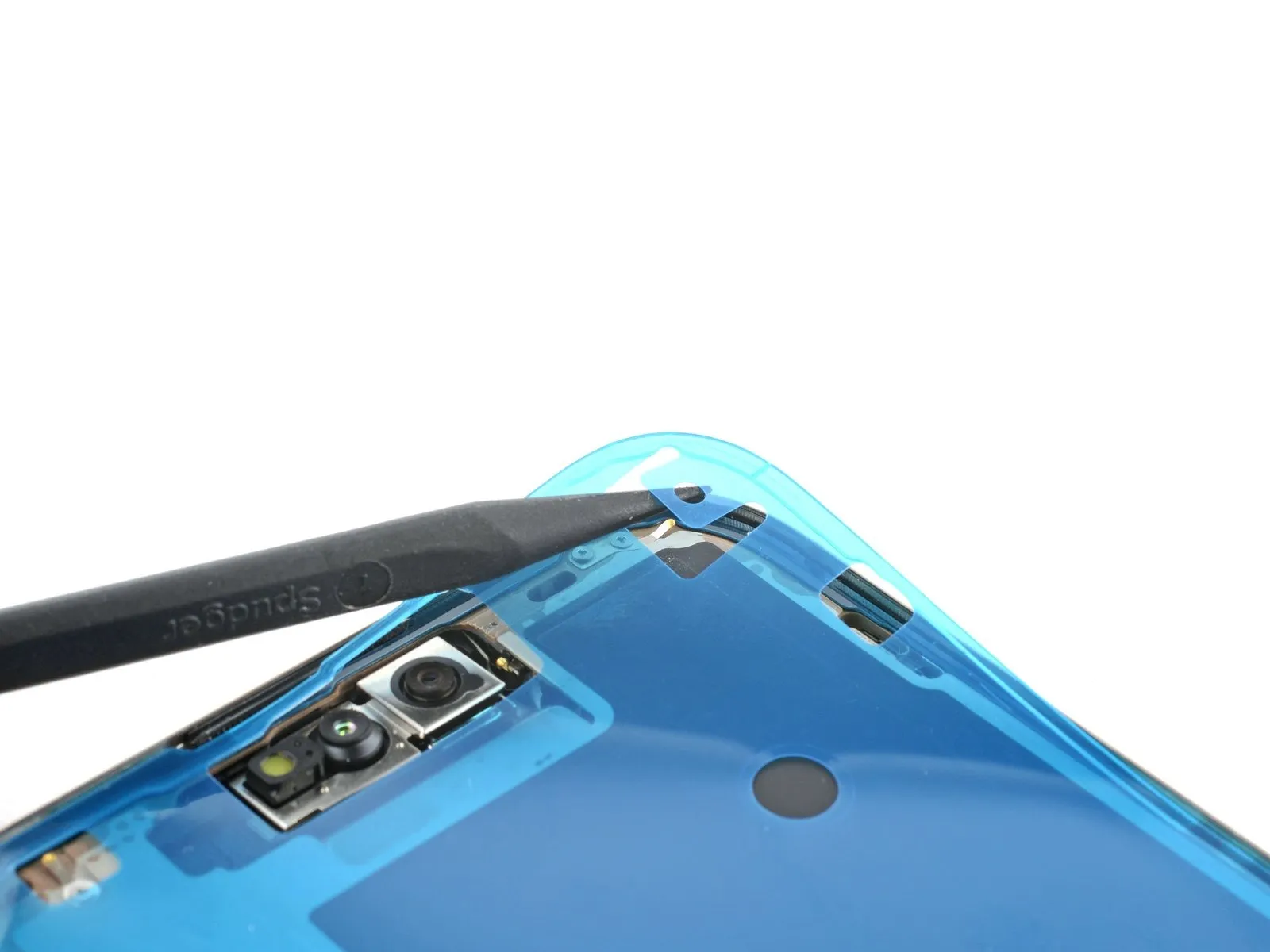
Step 9 | Heat the left edge
- Apply heat to the left screen edge using a hair dryer or heat gun, ensuring the surface reaches a temperature that is noticeably warm when touched.
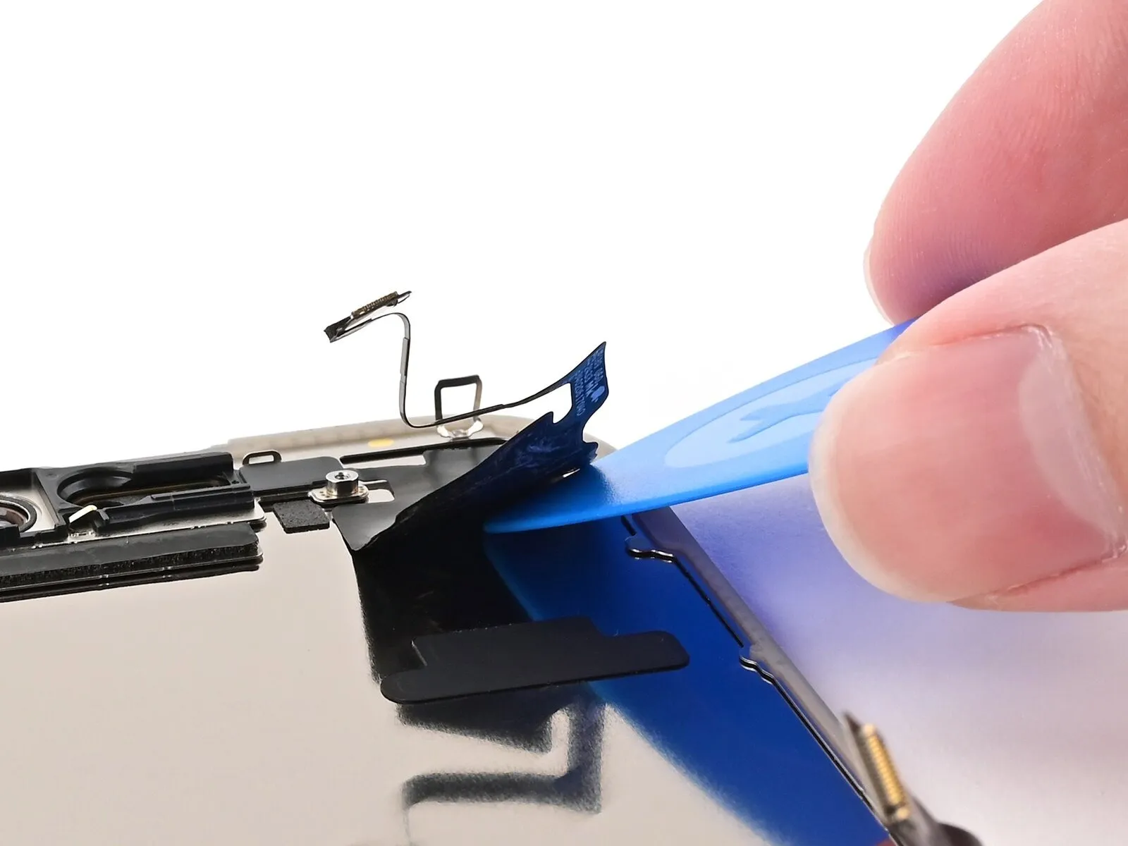
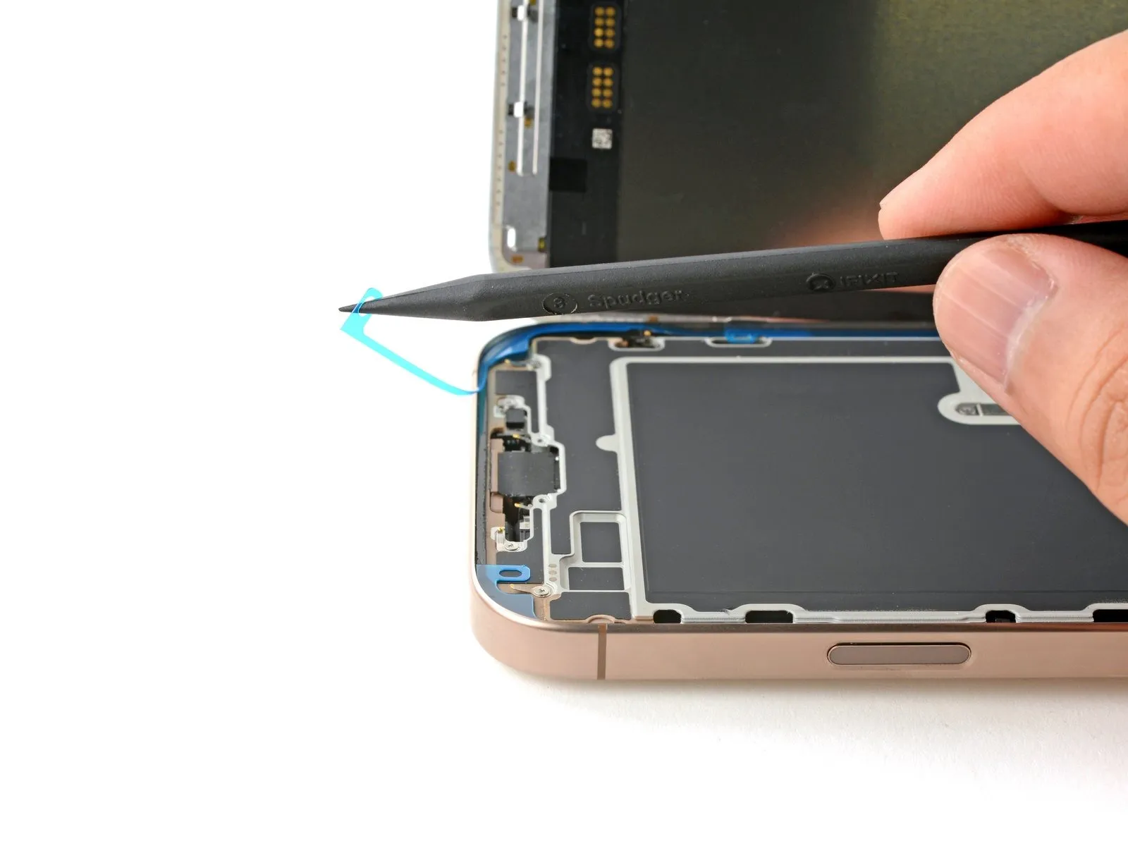
Step 10 | Separate the left adhesive
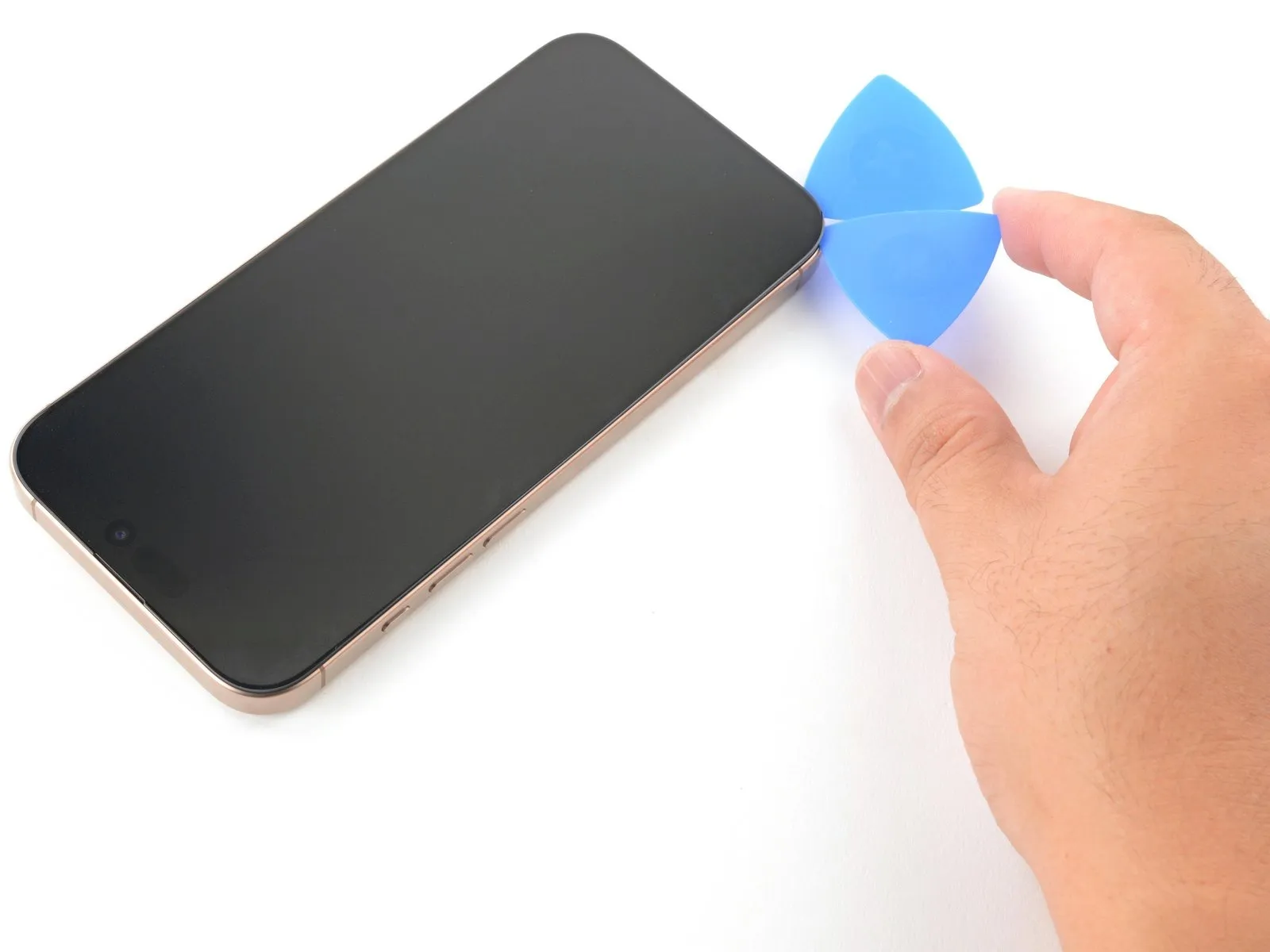
- To prevent damage to the spring contacts and cables, limit the insertion depth of the pick to a maximum of 3 millimeters.
- Position another opening pick near the first, specifically in the lower-left corner.
- Using the opening pick, carefully work along the left side of the display, gently prying to sever the adhesive bond and disengage the securing metal clips.
- As the clips slide past, you will notice and sense them disengaging.
- Maintain a positioning tool within the upper left aperture to obstruct adhesive re-adhesion.
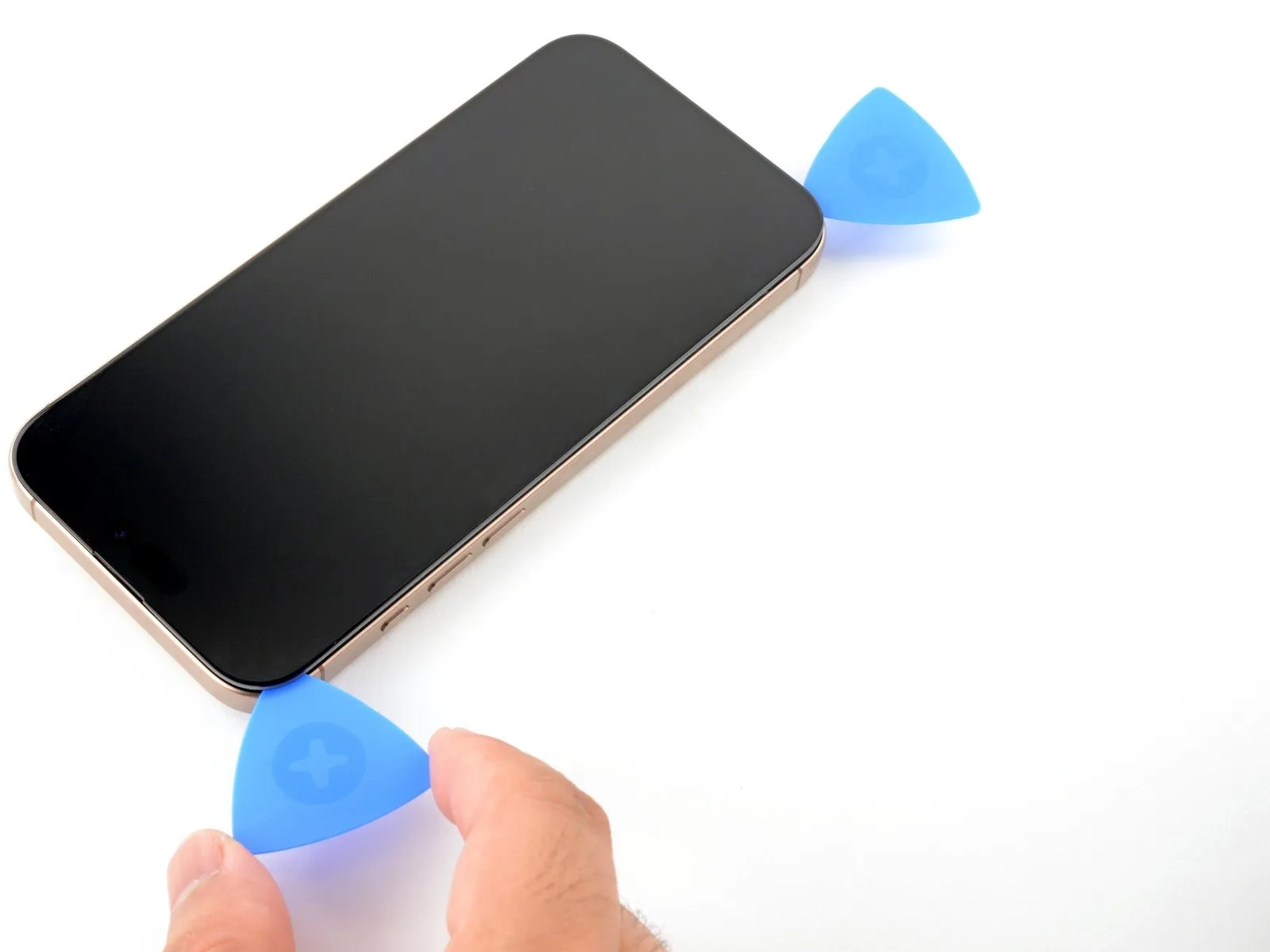
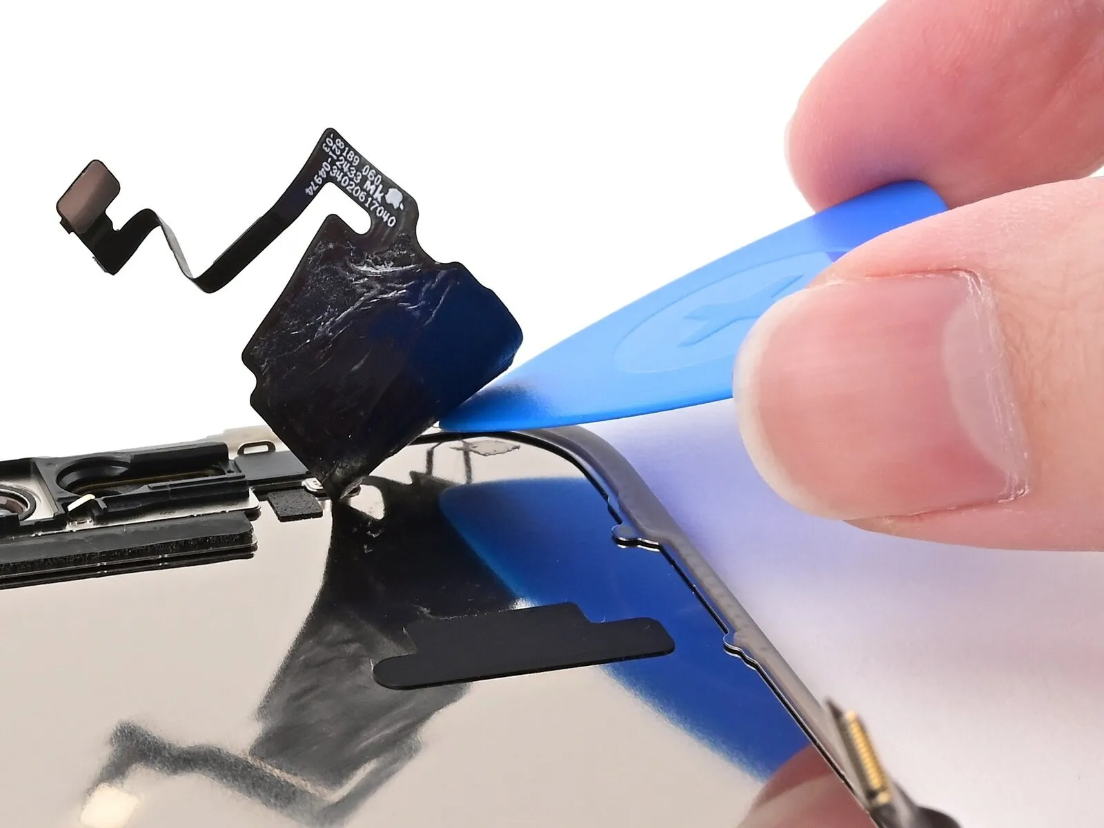
Step 11 | Separate the remaining adhesives

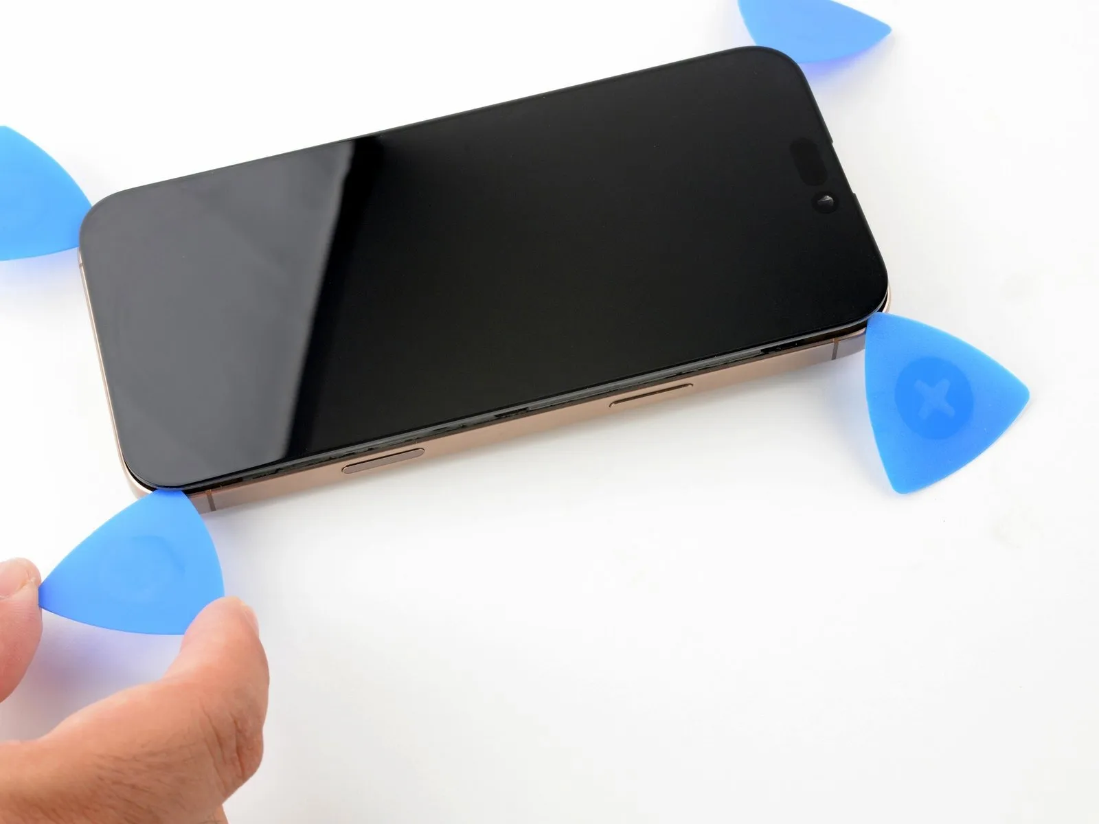
Continue the process of applying heat and carefully separating the screen from the device frame, working your way around all other sides.
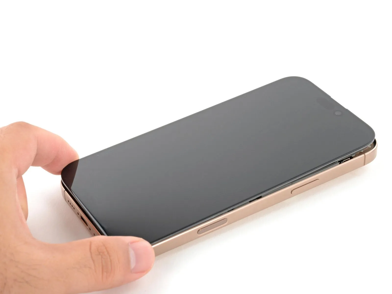
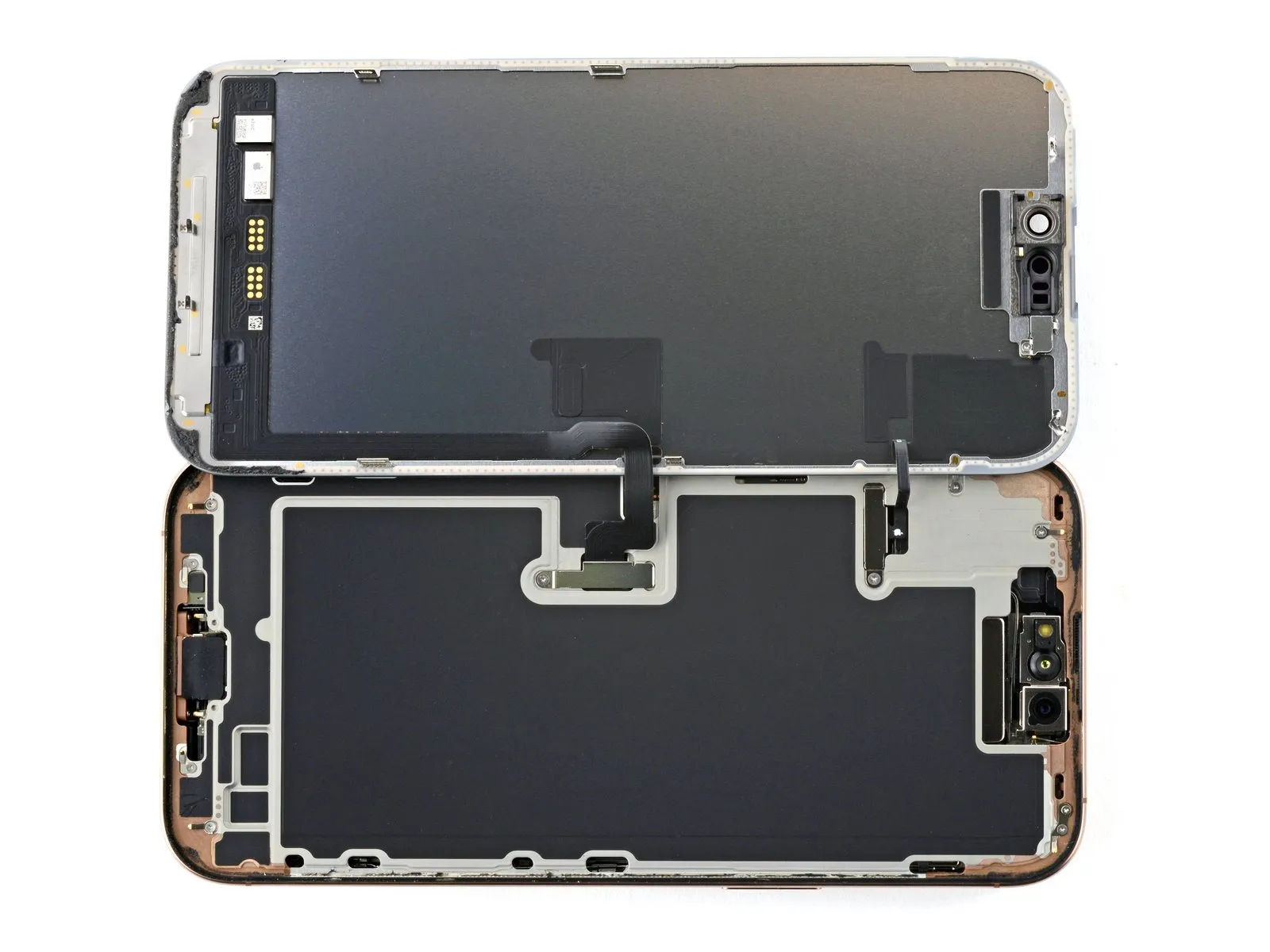
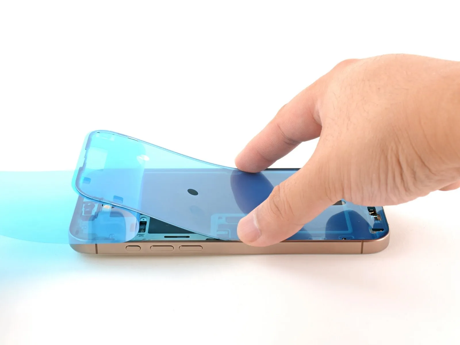
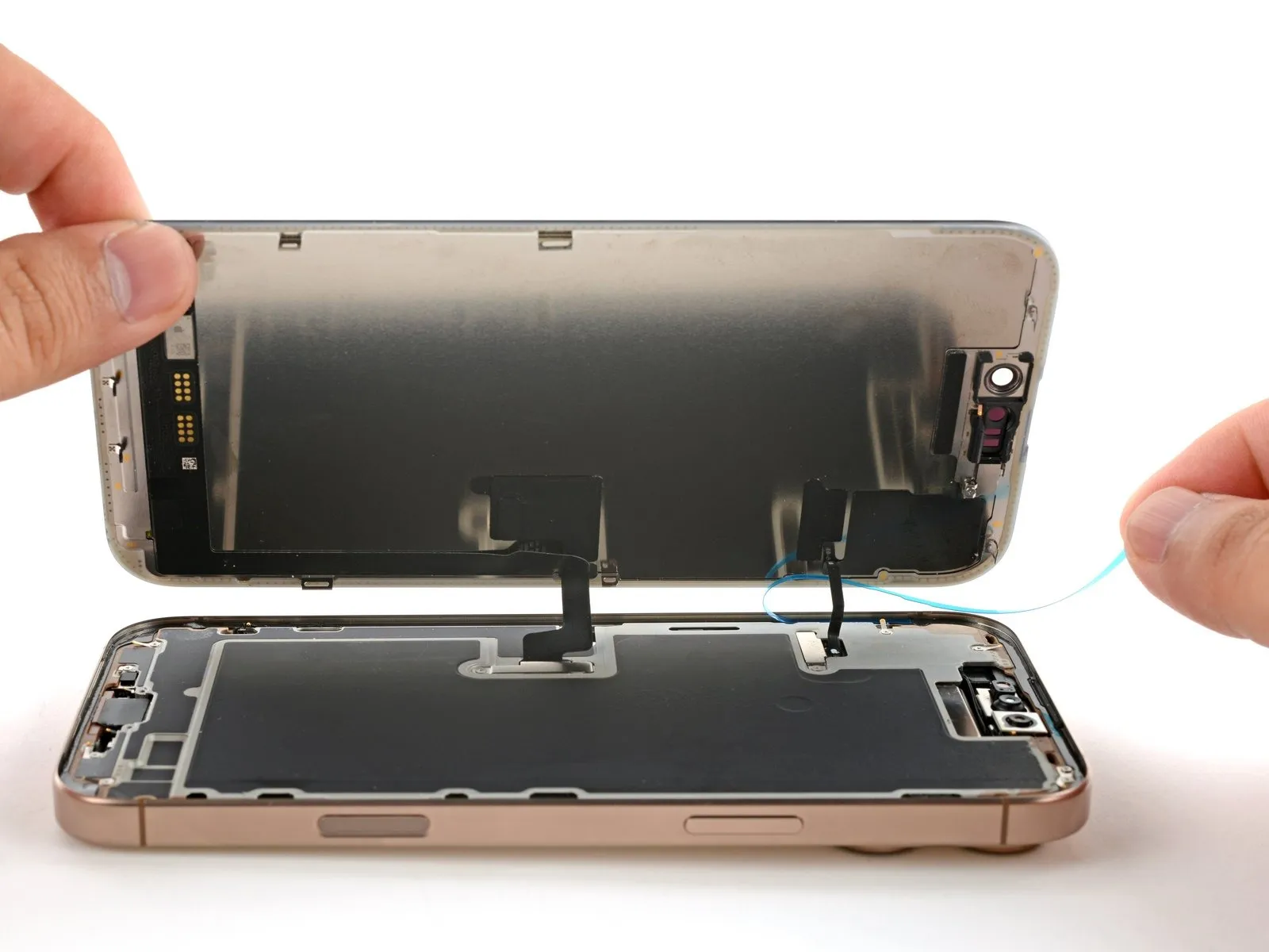
Step 12 | Swing open the screen

- Ensure the display panel is completely detached from the frame; if resistance is encountered, re-examine the edges using your pick, meticulously searching for any remaining adhesive or secured clips.
- Gently raise the screen, ensuring the retaining clips situated along the longer sides disengage from the surrounding frame.
- Carefully lift the display assembly away from the iPhone's left side, pivoting it open, and then position it horizontally on a clean, stable workspace.
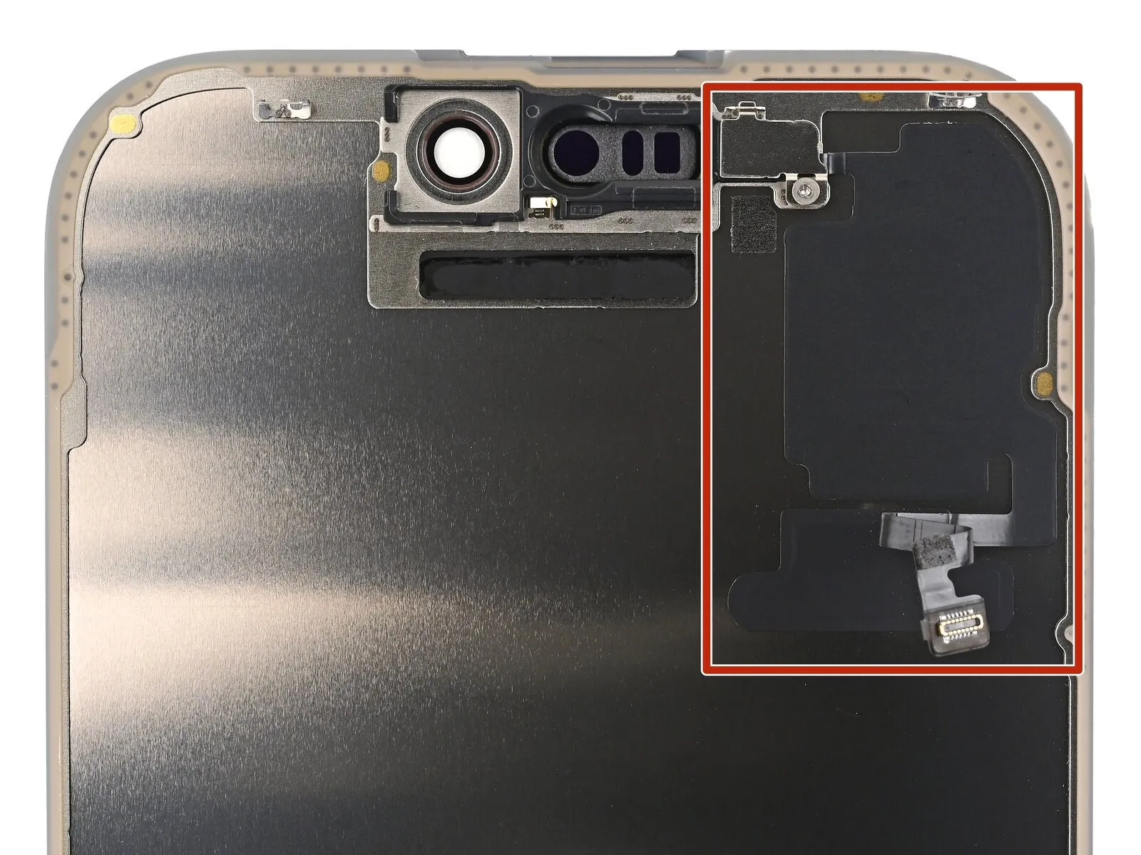
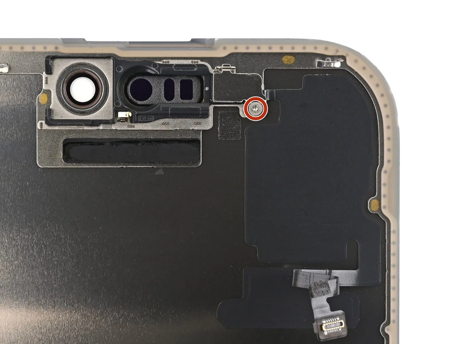
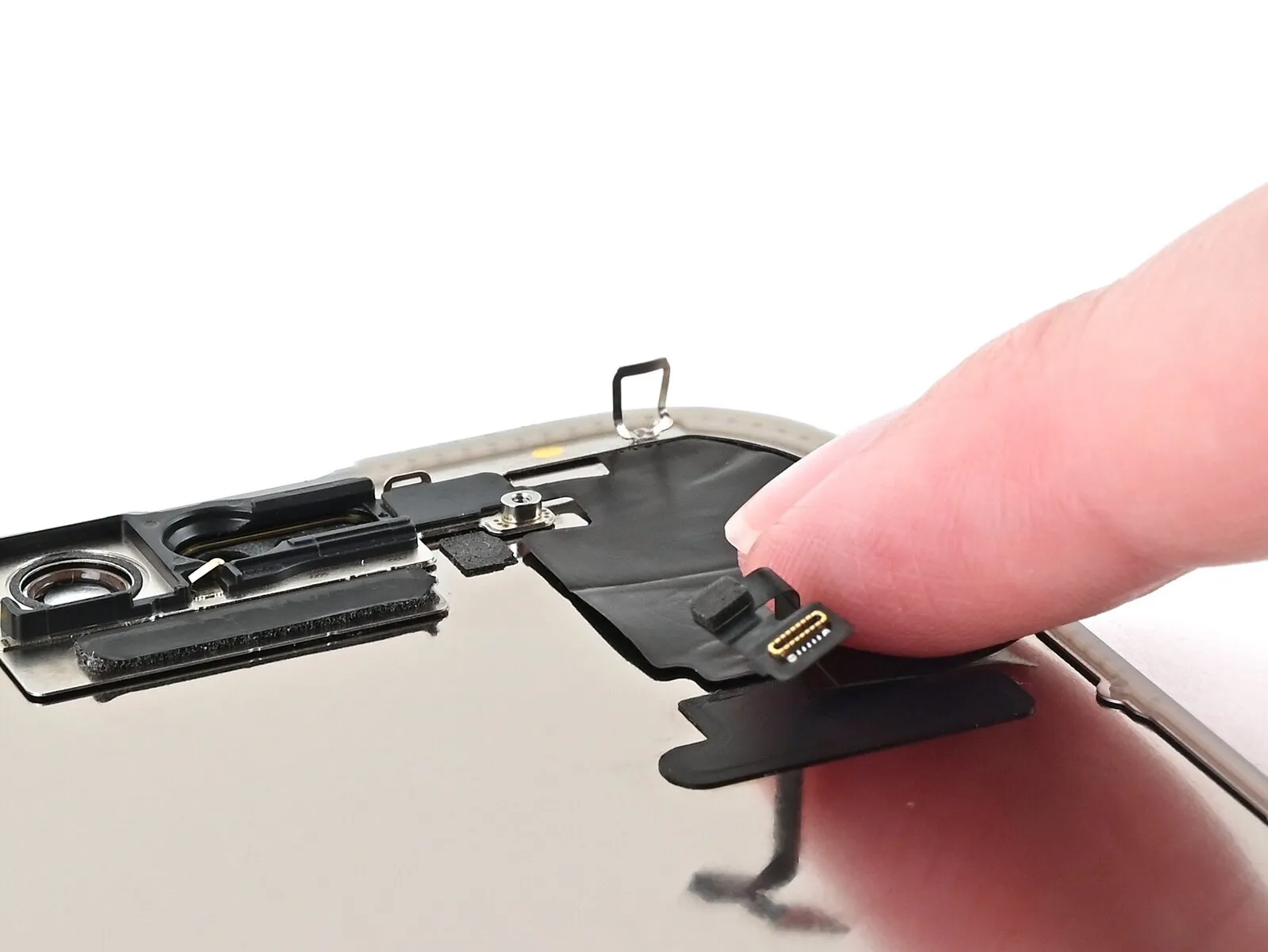
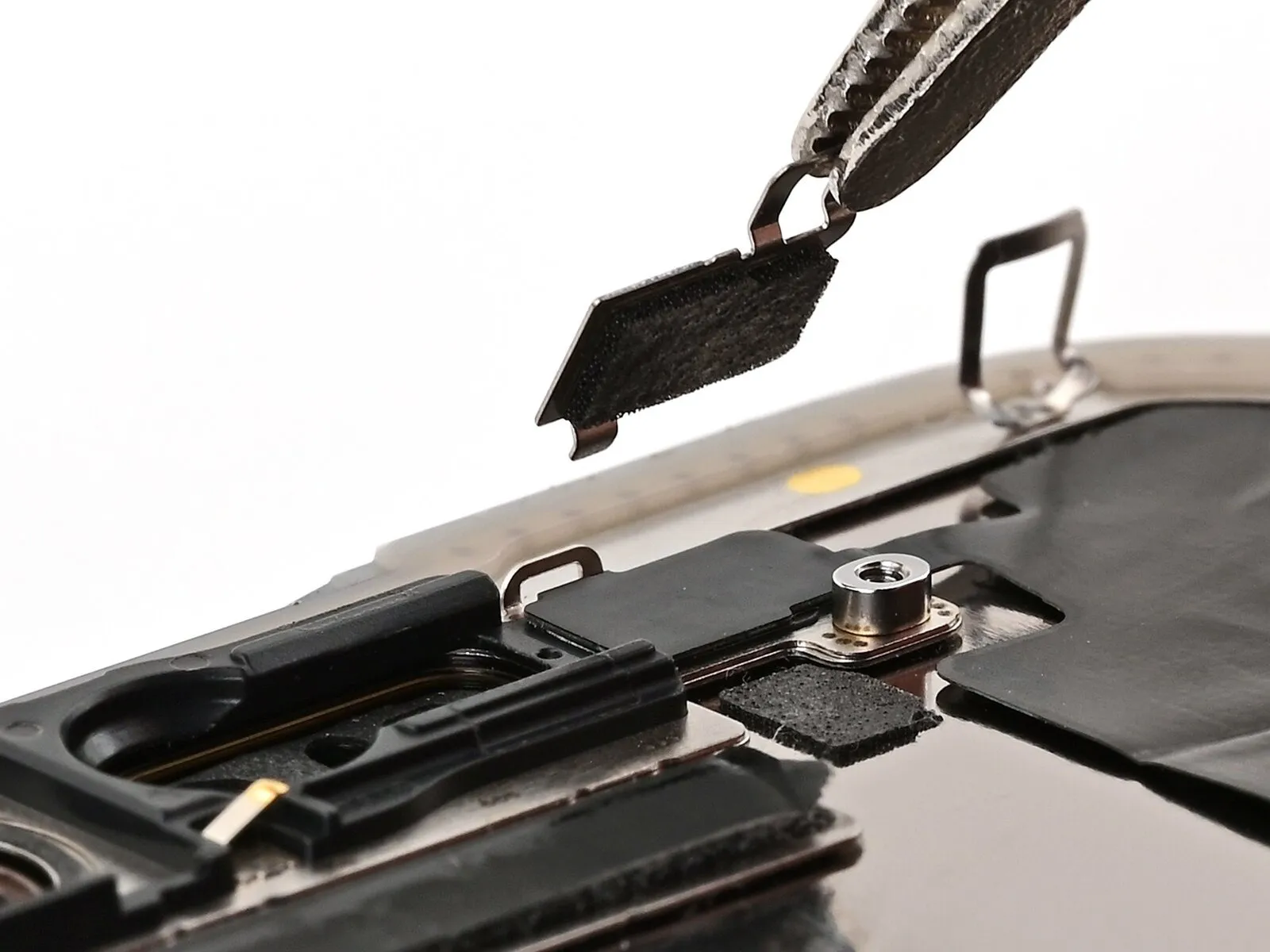
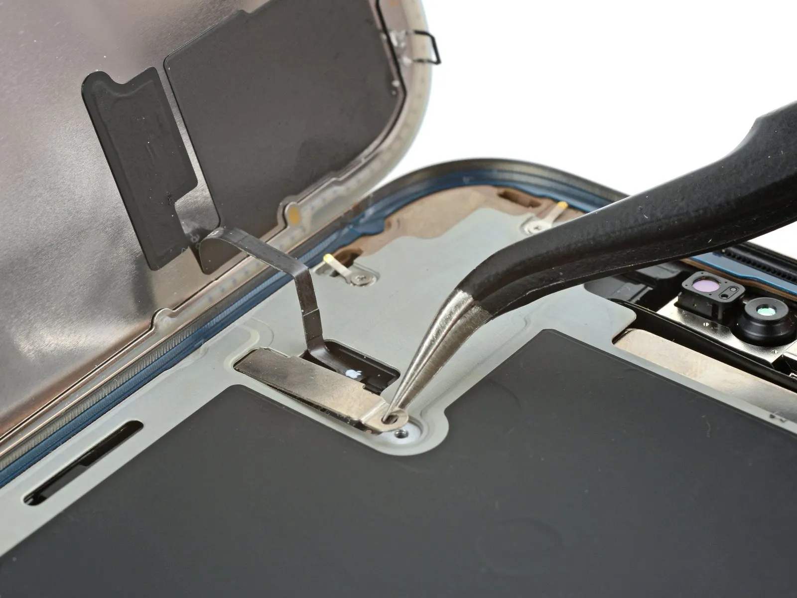
Step 13 | Remove the connector covers

- Employ a 3/8-inch socket wrench to loosen the retaining bolt, ensuring you maintain a firm grip and avoid over-tightening during reassembly, as excessive force can damage the threaded portion of the shaft.Use a Y000-sized tri-point screwdriver.Detach the pair of fasteners.Screws measuring 1.3 millimeters in length.Carefully attach the covers over the front sensor and display connector to ensure they are properly seated.
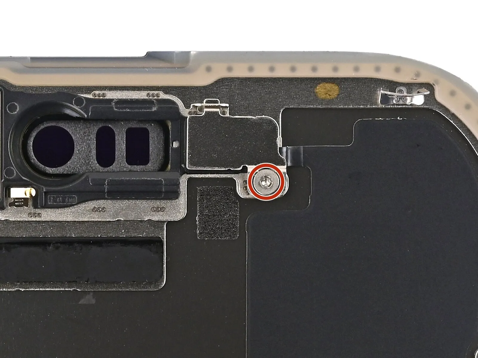
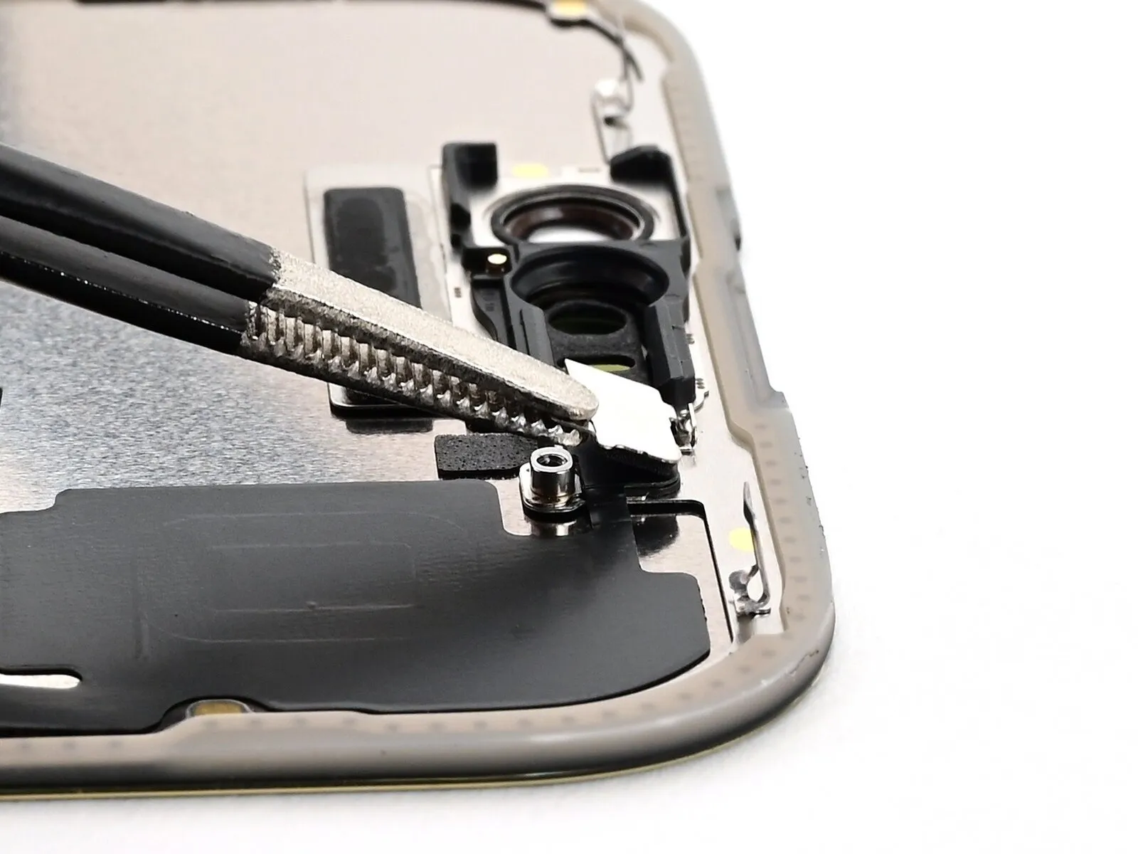
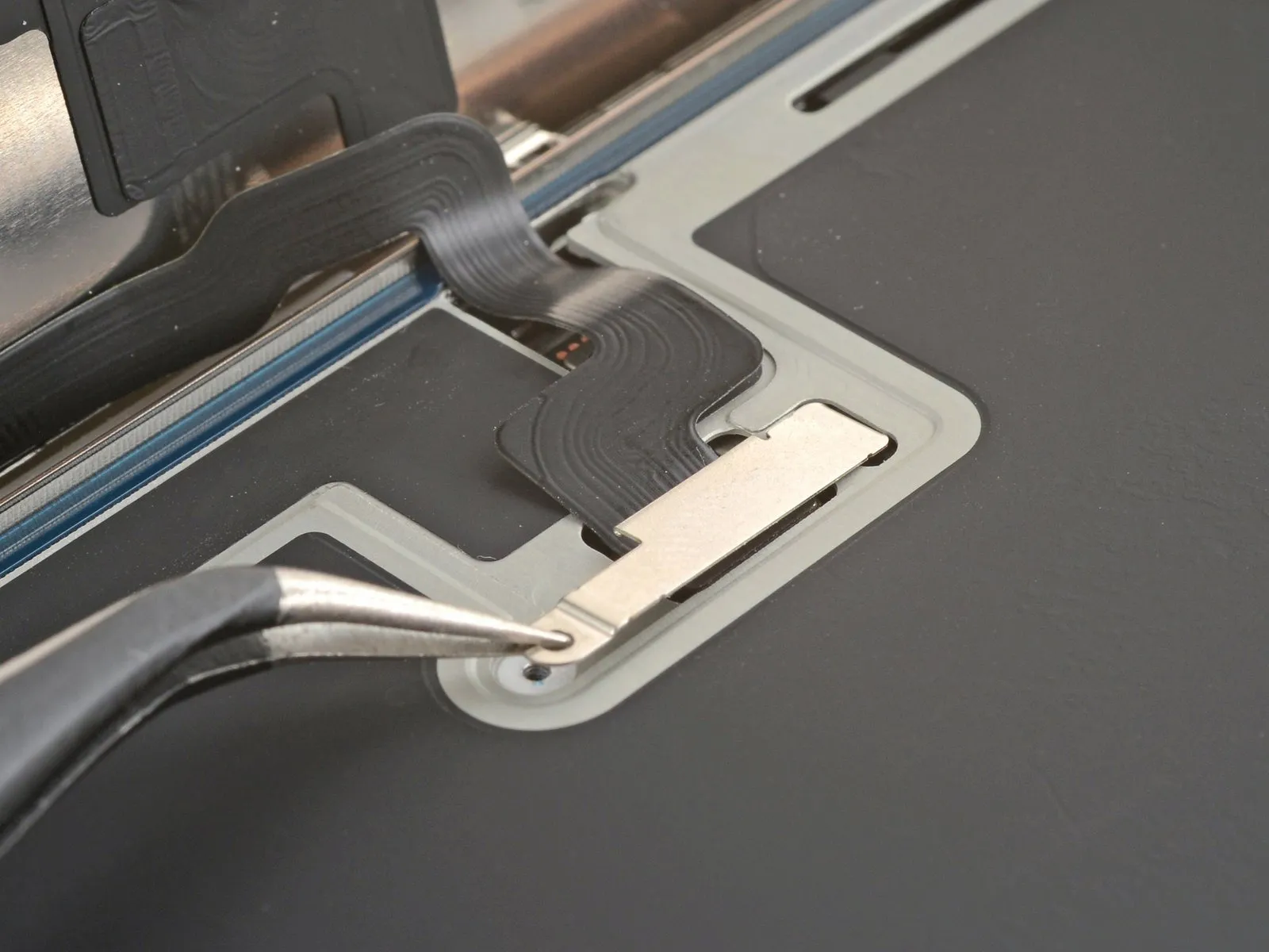
Step 14
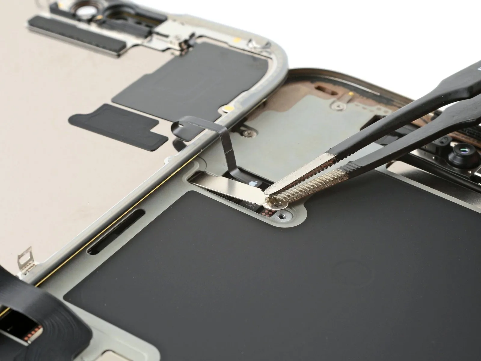

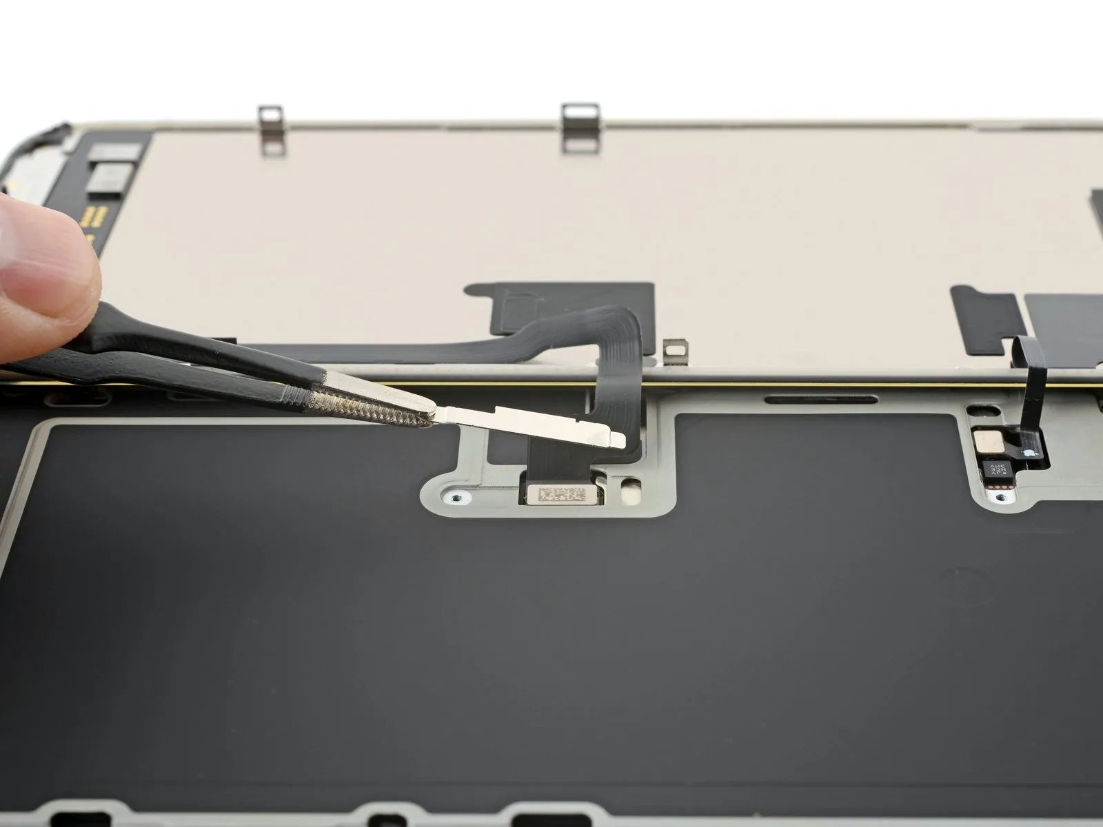
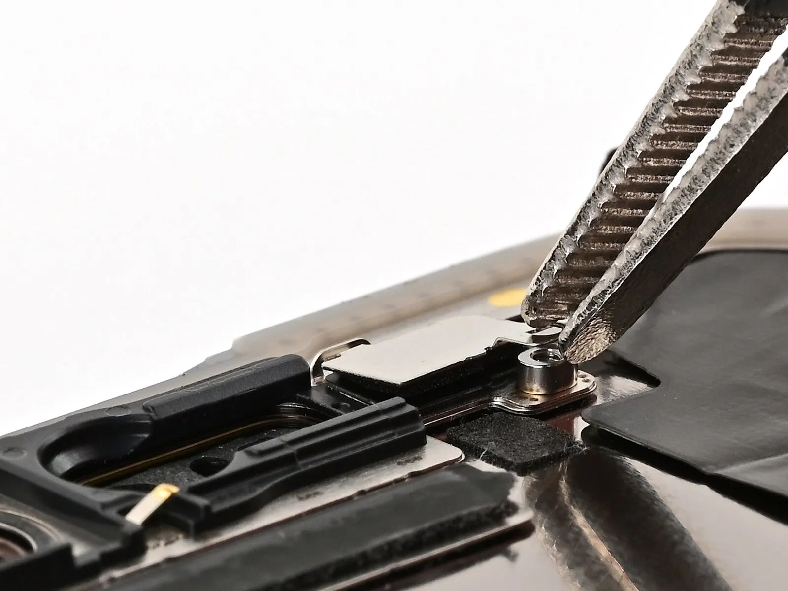
- Employ tweezers, positioning the tips close to the screw hole, to secure the front sensor connector cover.
Carefully raise the cover and detach it.
To detach the display connector cover, perform the same steps again.
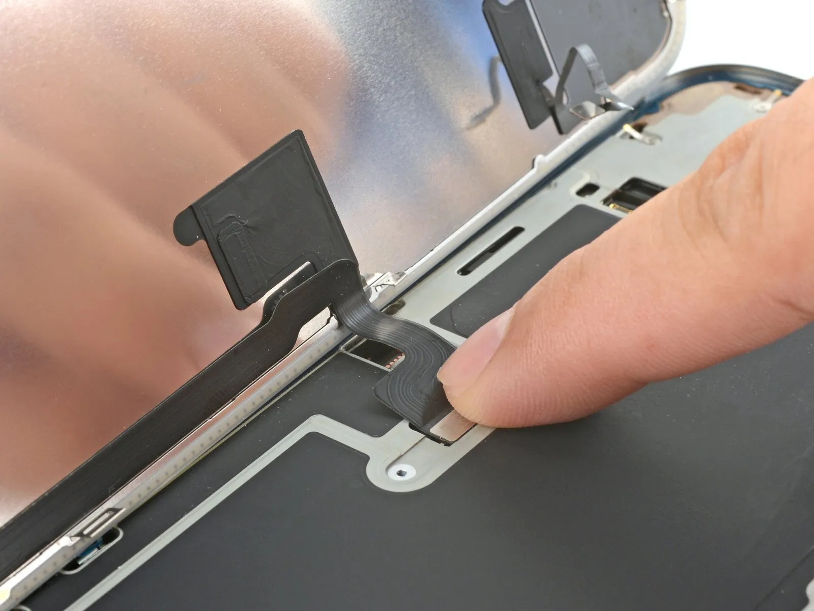
Step 15 | Disconnect the screen
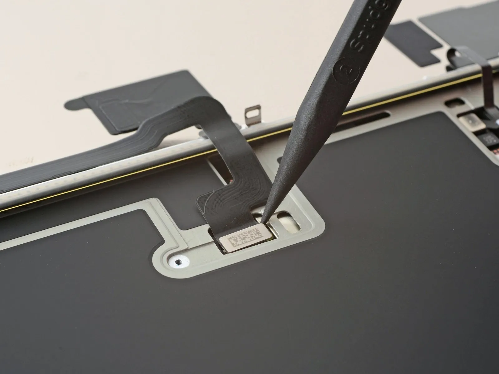

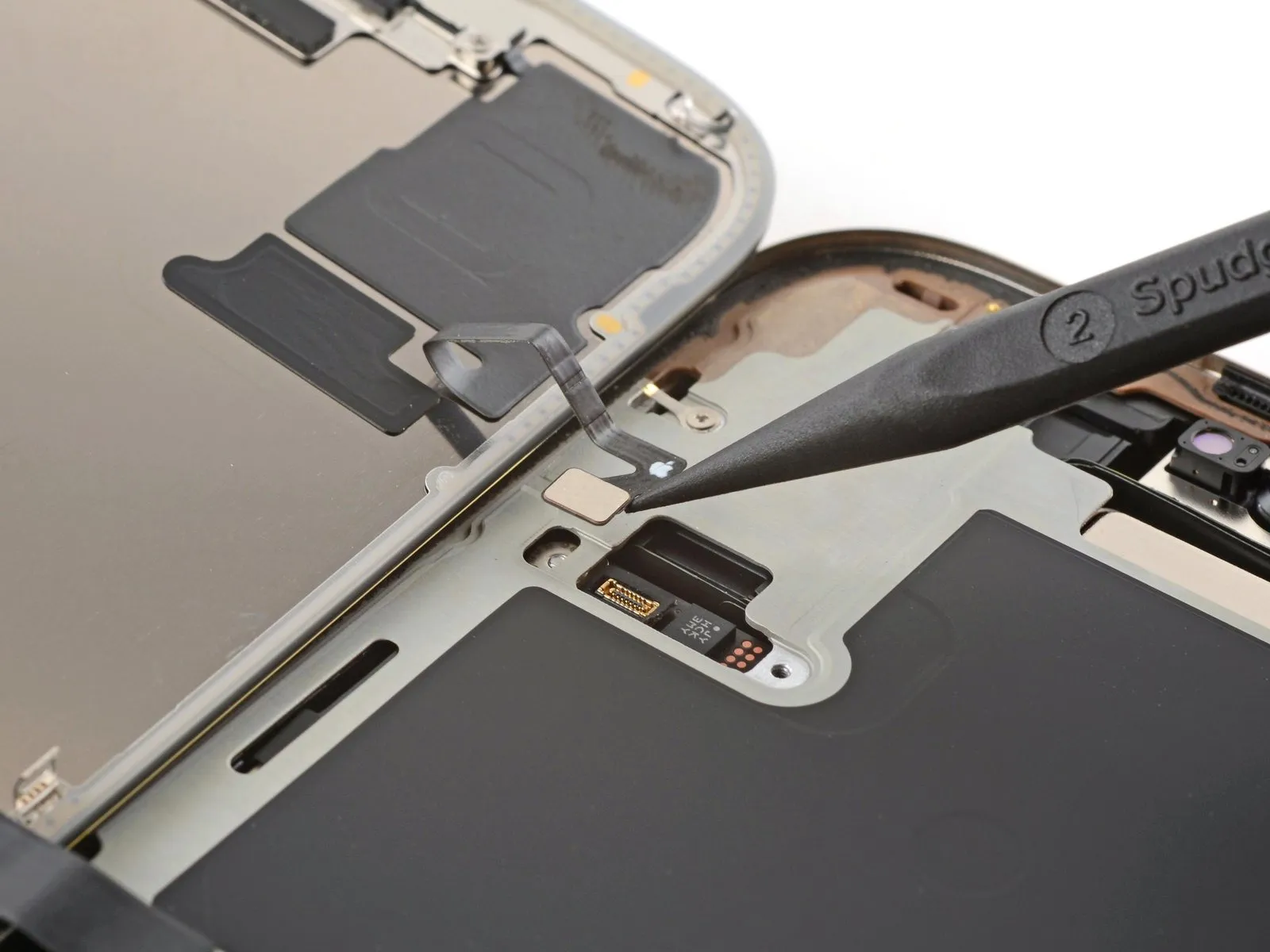
- Employ the pointed end of a screwdriver.Use a plastic pry tool, often referred to as a spudger.Release the display from its housing by carefully separating the connector.
Perform the same procedure on the connector for the front sensor press.
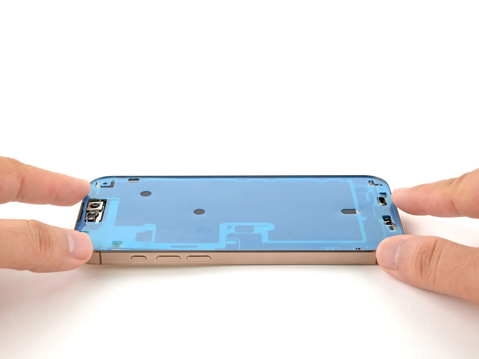
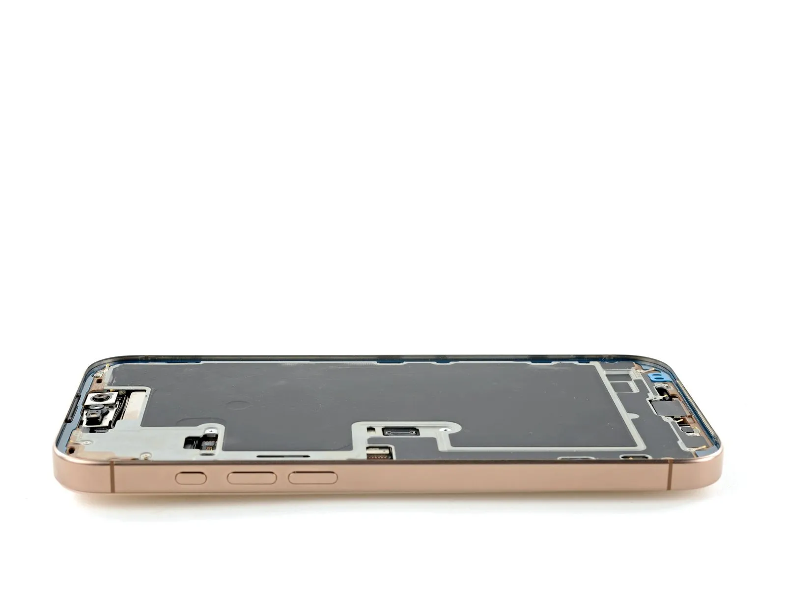
Step 16 | Remove the screen

- Carefully detach the screen assembly, ensuring no components are stressed, and then completely separate it from the device.
Step 17 | Disassembly complete

With the device now disassembled, proceed with the following instructions to reassemble your iPhone.
Visual differences in the assembly illustrations might occur based on your iPhone's specific version, but the steps remain accurate for all models.
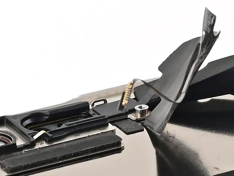
Step 18 | Ambient light sensor information
Positioned adjacent to the Face ID sensor opening, you'll find the ambient light sensor concealed behind the display.
Verify the new display unit already has a pre-attached component; if so, proceed with a click.Please provide the original text ("here") you want me to rewrite. I need the sentence or instruction to be able to fulfill your request.Proceed directly to step thirteen, bypassing the subsequent twelve procedures.
Step 19 | Remove the ambient light sensor bracket
Employ a 3/8-inch socket wrench to securely tighten the fastener to a torque of 15 Nm, ensuring no damage occurs to the surrounding components and observing all safety precautions.Use a Y000 tri-point screwdriver.Detach the component.A screw measuring 1 millimeter in length.Affix the bracket to the ambient light sensor, ensuring it is firmly attached.
Step 20
Carefully detach the ambient light sensor bracket by gently raising it with tweezers or your fingertips.
Step 21 | Heat the ambient light sensor cable

- Apply warm air from a hair dryer.,Apply warm air with a heat gun.Using a 5/32-inch hex key, carefully tighten the set screw located on the motor shaft to a torque of 3.0 Nm, ensuring you observe all safety precautions regarding pinch points.Use the iOpener.Apply gentle heat to loosen the adhesive securing the ambient light sensor and its cable.
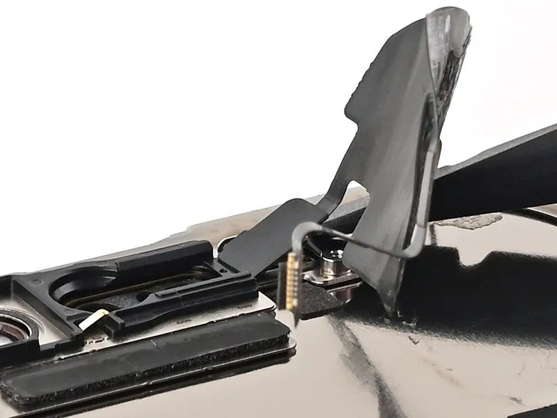
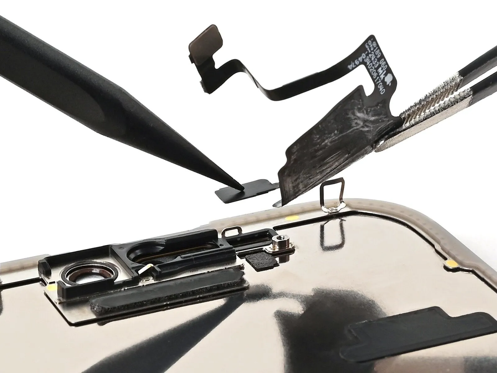
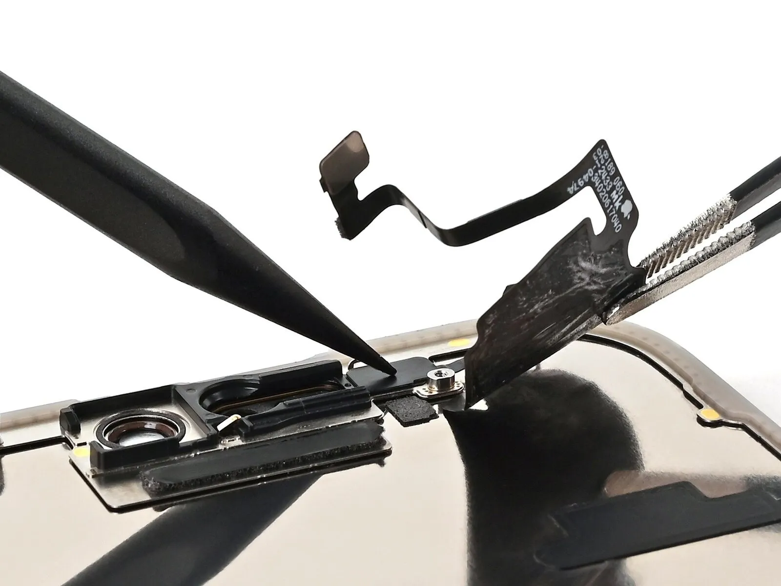
Step 22 | Peel up the ambient light sensor cable

- Exercise caution and proceed deliberately.Exercise extreme caution when handling the cable, as it is fragile, particularly close to the sensor; avoid attempting to raise the sensor at this stage.
Carefully insert a separating tool beneath the ambient light sensor cable, initiating the separation from the screen's underside, near the connector, and progressing upwards to release the cable completely.
Increase the temperature to facilitate adhesive separation if resistance is encountered.
Step 23 | Reheat the ambient light sensor
- Apply warm air from a hair dryer.,Apply warmth using a device that generates heat, ensuring the temperature remains consistent and controlled.Using a 5/32-inch hex key, carefully tighten the set screw located on the motor shaft until snug, but do not overtighten to avoid damaging the threads.Use the iOpener.Apply gentle heat to the adhesive securing the ambient light sensor to facilitate its release.
Step 24 | Pry up the ambient light sensor
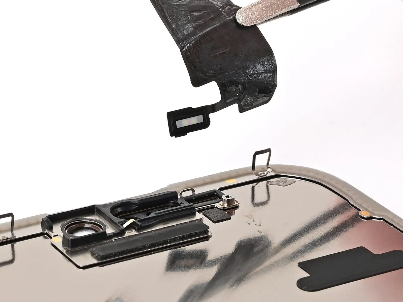
- To prevent damage to the delicate cable connected to the ambient light sensor, proceed with caution; if resistance is encountered, increase heat application rather than applying additional pressure.
Carefully lift the ambient light sensor away from its socket using the flat spudger, applying force to the side containing the exposed cable.
Disconnect the electrical connector, then detach the sensor from the housing using a trim removal tool to release the retaining clips.
Step 25 | Prepare the ambient light sensor
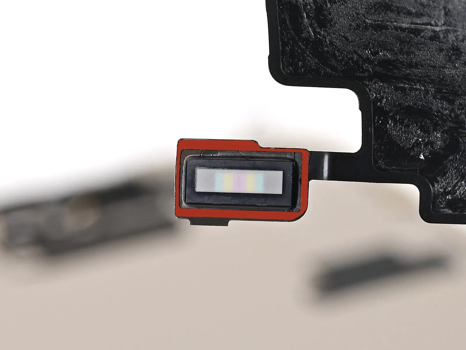
- Employ the specified tool to apply a force of 15 Nm, ensuring the fastener is tightened to the correct torque specification and avoiding damage to the component.Employ fine-tipped pliers or similar precision instruments.Ensure the ambient light sensor's surrounding area is free of excess adhesive; the adhesive should be carefully reapplied to create a defined border along the perimeter of the sensor's rectangular protrusion.
- To compensate for any adhesive residue left on the device or if the original adhesive is compromised, apply a 1 mm wide piece of double-sided tape to the top edge.
Step 26 | Place the ambient light sensor
- Carefully position the ambient light sensor so that it fits snugly within the designated cavity on the rear surface of the screen.
Employ a 3/8-inch socket wrench to loosen the retaining bolt, ensuring you maintain a firm grip and avoid over-tightening during reassembly, as excessive force can damage the threaded insert.Use a spudger.Carefully push the ambient light sensor into its designated cavity.
Step 27 | Warm the ambient light sensor cable
- Apply gentle heat to the adhesive securing the ambient light sensor and its cable, using a hair dryer, heat gun, or iOpener; ensure the adhesive becomes pliable, but avoid excessive heat.
Step 28 | Press the ambient light sensor
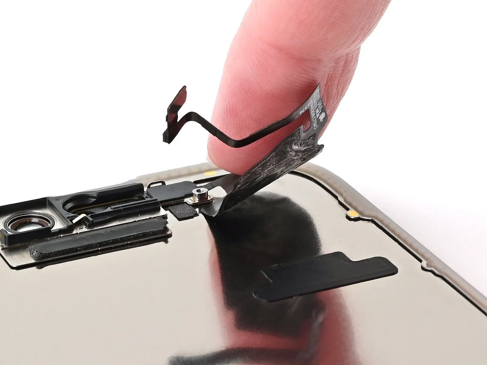
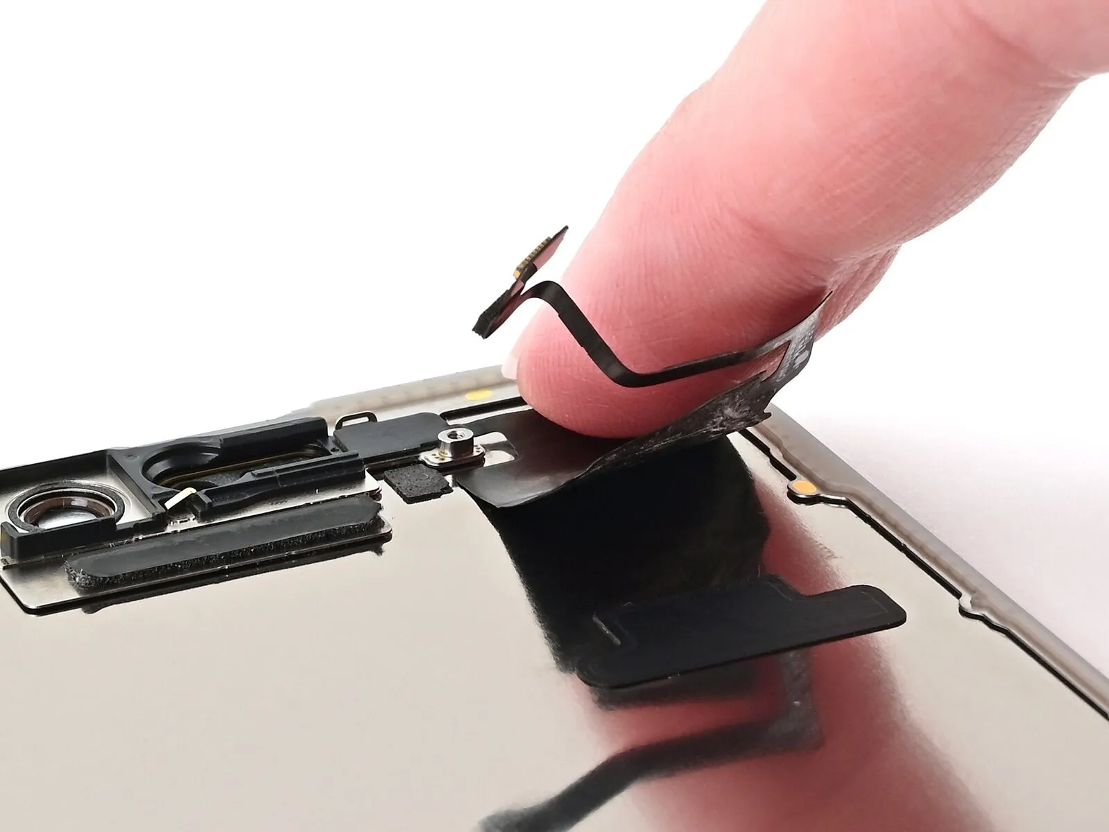
- Apply downward pressure to the ambient light sensor cable with your fingertip.
To secure a loose ambient light sensor cable, use a limited number of small sections of thin, double-sided adhesive tape.Apply Tesa tape.Connect the sensor cable to the designated port located on the rear of the sensor.
Step 29 | Install the ambient light sensor bracket

- Employ the specified tool to perform the action.Employ fine-tipped pliers or similar precision instruments.Carefully maneuver the ambient light sensor bracket using your fingers to secure it to the sensor's rear, ensuring it is properly seated.
Step 30
- Secure the component with a Y000 tri-point screwdriver.A screw measuring 1 millimeter in length.Affix the bracket to the ambient light sensor, ensuring its stability.
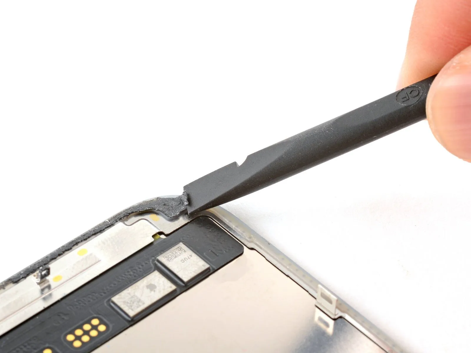
Step 31 | Remove the adhesive and its residue
- Carefully detach the adhesive remnants from the iPhone's frame using a spudger or tweezers.
Exercise caution to avoid damaging the delicate grounding clips; should one become displaced, carefully reposition it using your fingers or tweezers.
Step 32
Before reattaching the display panel, thoroughly clean any residual adhesive from its rear surface.
Step 33

- Employ a 5/16-inch socket wrench to loosen the retaining bolt, ensuring you maintain a firm grip on the component to prevent it from rotating while the bolt is removed, and always wear safety glasses to protect against potential debris.Use a cleaning cloth made of material that does not leave behind fibers.Using a coffee filter and isopropyl alcohol with a concentration exceeding 90%, thoroughly wipe the frame and screen surfaces from which the previous adhesive was detached.
- To ensure optimal cleaning, move the cloth across the surface in a single, continuous motion, avoiding a reciprocating movement.
- Exercise caution to avoid damaging the delicate grounding clips; should one become displaced, carefully restore it to its original position using your fingers or tweezers.
- Careful execution is essential; a thoroughly cleaned frame surface enables the new adhesive to spread uniformly, which is critical for a strong, reliable bond.
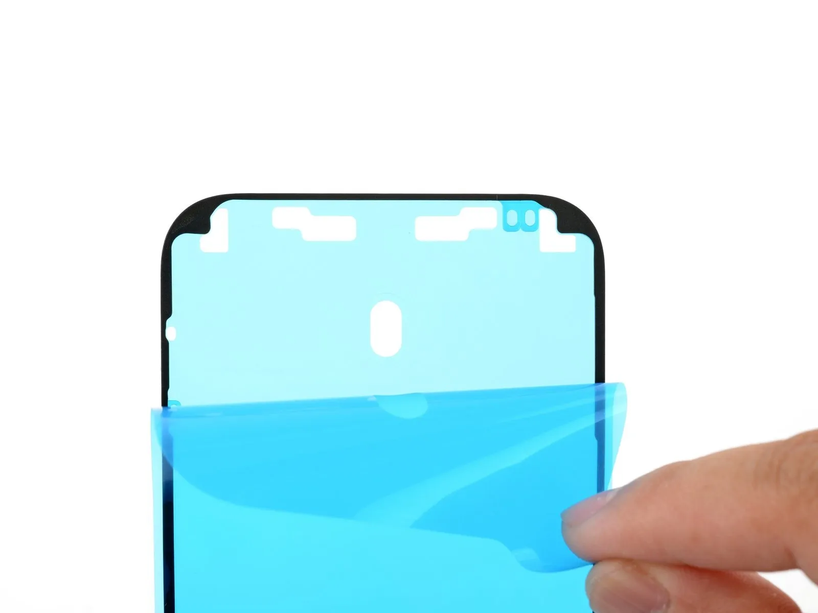
Step 34 | Apply the replacement adhesive

- Position theA self-stick backing is present.Position the component atop the frame, ensuring alignment according to its designated markings.
- Carefully observe the frame's details, like the camera opening, to anticipate the adhesive's placement.
Step 35
- Carefully hold the corner tab.A self-stick backing is present.Carefully remove a portion of the protective liner, revealing approximately one-third of the adhesive surface.
- Because the adhesive surface is highly adhesive, prevent contact with other materials until you intend to bond it to the frame.
- Remove the protective layers from the adhesive until the surface designed to bond with the frame is revealed.
Step 36
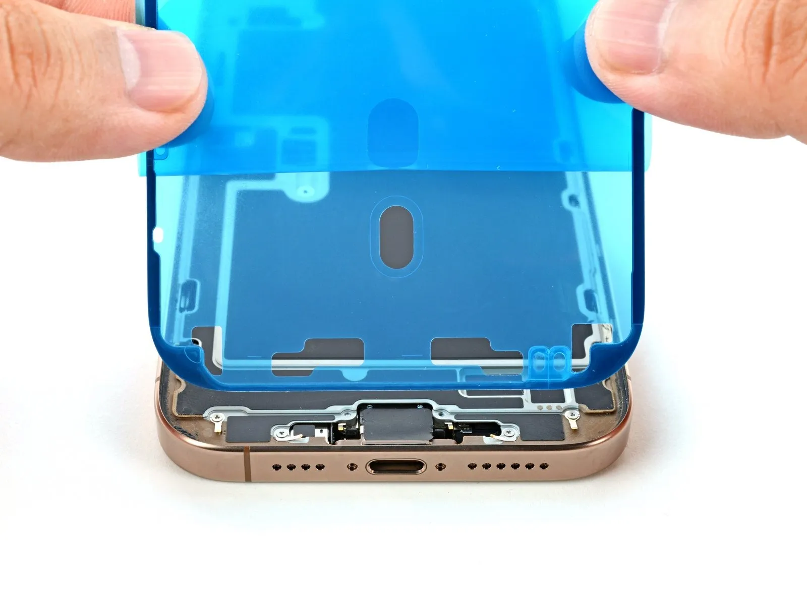
- Ensure the visible perimeter is precisely positioned.Double-sided tapeAlign the component's border precisely with the iPhone's outer casing.
Because the adhesive bonds immediately upon contact, any adjustments after initial placement are impossible; instead, the application must be completely removed and redone using fresh adhesive.
Ensure proper positioning, then apply even pressure to secure the adhesive strip.
Step 37

- Carefully remove the backing liner while applying even pressure to secure the adhesive.
Proper adhesive placement ensures the borders seat flush and precisely.
Gently adjust the adhesive's position by drawing the extended sides toward the frame to ensure proper alignment.
Should the adhesive exhibit creasing or wrinkling, discard the affected material and reapply with a new portion.
Carefully observe that the specified torque of 25 Nm must be applied when tightening the M6 bolt using a torque wrench to prevent damage to the component.Should a replacement set of adhesive strips be unavailable, the iPhone can be reassembled and used without them; however, be aware that the device's water resistance will be reduced until the adhesive is properly replaced.
Step 38
Carefully apply pressure along the device's edges with a spudger to release the adhesive securing it.
Exercise caution to avoid damaging the delicate grounding clips; should one become displaced, carefully reposition it using your fingers or tweezers.
To prevent electric shock or potential injury, disconnect the power supply and allow the component to cool completely before proceeding with any maintenance or repair procedures.Apply gentle pressure to avoid distorting or overextending the adhesive.
Step 39

- Carefully detach the large front liner by gently prying up the pull tab, which is typically located along an edge of the liner, using a spudger or your fingertips.
Carefully remove the substantial front adhesive liner by grasping and lifting the designated pull tab.
Small adhesive-protective liners are likely still in place along the edges; leave these in position for now to avoid unintended adhesion during reassembly of the iPhone.
Step 40 | Reconnect the screen

- Apply firm, even pressure with a fingertip to secure the display connector's connection.
Ensure proper positioning of the wide press connector, then apply even pressure to one side until a distinct click confirms secure engagement; subsequently, repeat this process on the opposing side.Carefully observe that the specified torque of 25 Nm must be applied when tightening the M6 bolt using a torque wrench to prevent damage to the sensor housing.Avoid applying pressure to the central area; misalignment risks pin deformation, which will result in irreversible component failure.
Ensure the front sensor connector is firmly seated by applying downward pressure.
Gently position the connector above its corresponding socket, then apply firm, even pressure with a fingertip until you hear a distinct click, indicating secure engagement.To prevent electric shock or potential injury, disconnect the power supply and allow the component to cool completely before proceeding with any disassembly or repair procedures.Carefully align the connector, avoiding any excessive force; if it doesn't seat properly, readjust its position and attempt connection once more.
Carefully observe that the specified torque of 25 Nm, achievable with a 1/4-inch torque wrench, must be applied when tightening the fastener to prevent damage.Before reassembling the device, verify all features are working correctly with the iPhone powered on, then ensure it is fully shut down to proceed.
To troubleshoot a non-responsive iPhone, establish a connection to a power outlet and attempt powering on the device.
Step 41 | Install the connector covers
- Secure the display connector cover by inserting its tab into the corresponding opening in the frame, then position the cover flush against the frame.
- Replicate the procedure for the cover protecting the front sensor connector.
Step 42
Step 43 | Remove the final liners
- Carefully prevent the screen from moving, then employ your fingers or a spudger to detach the perimeter liners completely, revealing the adhesive underneath.
- Avoid direct contact with the adhesive backing to prevent skin irritation.
- Carefully inspect the frame and screen, ensuring all liners have been completely removed; confirm the absence of any remaining liners.
Step 44 | Install the screen onto the frame
Step 45


- Position the screen against the frame, initiating the placement with the uppermost border.
- A sensation of obstruction indicates that the component is not moving freely and requires further inspection.Secure the component using the retaining clip.The clip might be deformed and compressed against the frame; carefully examine the area where it's binding and restore its shape with gentle manipulation.
- Verify that the display panel's perimeter isn't being compressed.Ensure all wiring harnesses and connectors are properly secured and free from damage, with each cable measuring precisely 12 inches in length and utilizing a 1/4-inch diameter ferrule where applicable, and always observe caution when handling to avoid pinching or abrasion..
Step 46 | Apply heat to the perimeter

- Apply warmth around the screen's edges with a hair dryer, heat gun, or iOpener, ensuring the surface reaches a temperature just beyond comfortable touch.
- Applying warmth loosens the adhesive, facilitating a stronger connection.
Step 47 | Apply pressure to the perimeter


Apply consistent, even pressure with your fingertips along the entire edge.Using appropriate safety precautions, carefully handle the device, referred to as an iPhone..
Step 48


- Position the iPhone, with the display facing downward, on a clean, level workspace.
- To shield the back glass's surface from scratches, apply masking tape along its entire outer edge.
- Using coins, build a circular barrier along the edge of the back glass, raising it to the same height as the rear camera lenses.
- To ensure proper adhesion, secure the device's edges with vise clamps.
Step 49


- Position the component carefully, ensuring alignment with its designated markings, and secure it using the specified fasteners, applying a torque of 4.5 Nm with a torque wrench to prevent over-tightening and potential damage.Apply downward pressure equivalent to the weight of three to four standard-sized, hardcover books.Position the device directly and evenly atop the iPhone.
- To prevent potential marking of the lower book cover's surface, avoid placing valuable items underneath during this process.
- Allow the books to remain positioned atop the device for approximately half an hour.
- Applying force will engage the adhesive properties.
Step 50 | Install the pentalobe screws
Employ a 3/8-inch socket wrench to loosen the retaining bolt, ensuring you apply consistent pressure to avoid damaging the threaded connection; torque the bolt to 15 Nm upon reinstallation, and be aware that the spring clip may dislodge during this process.Use a P2 driver with a pentalobe tip.Secure the pair using the provided fasteners.Screws measuring 7.4 millimeters in length.Flanking the charging port are two locations.