iPhone 17 Pro Battery Replacement
Using these instructions, you can substitute a faulty or deteriorated component.Carefully disconnect the battery, observing proper polarity and ensuring no shorts occur, then safely remove it from the device.Within an iPhone 17 Pro.
Using appropriate safety precautions and specialized tools, carefully handle the device, identified as an iPhone.A battery's ability to retain 80% of its original power can last through as many as 1000 complete charge and discharge cycles.Using appropriate safety precautions and tools, carefully handle the device, identified as an iPhone.If the device requires frequent charging or exhibits reduced performance, battery replacement is likely necessary.
- To restore battery health information following the replacement, utilize the Apple Repair Assistant to re-enable the relevant system data.
- Beginning with iOS version 26, the battery health feature accurately reports data for both Apple-supplied and third-party replacement batteries.Carefully disconnect the battery, observing proper polarity to avoid short circuits, and ensure the terminals are clean before reattachment, noting the voltage is 12V.Using a 5/32-inch hex key, substitute the damaged component with a new one, ensuring all technical specifications and measurements are identical.
Ensure you have the required tools and materials, including [list of tools and materials].Apply fresh adhesive strips, specifically designed for screen securing, to the display assembly.Ensure all preceding steps have been successfully executed.
Step 1 | Safety precautions


To prevent fire hazards, ensure the iPhone's lithium-ion battery is depleted to a level below 25% charge prior to commencing the repair procedure; a fully charged battery poses a fire risk if compromised.
- Disconnect all wires and cords connected to the device.
- Simultaneously press and maintain the power button alongside either volume button, then move your finger across the screen to initiate the power-off sequence.
Step 2 | Cracked glass preparation


To prevent potential injury or equipment damage, exercise care during this step.To prevent cuts or further damage during the repair process, proceed with the following step if the phone's screen is broken and contains fragments of glass.
- To prevent shattering and facilitate suction cup adhesion, thoroughly cover the damaged glass with packing tape strips.
- Apply a continuous, non-overlapping strip of tape along the lower edge, ensuring it's sized to accommodate a suction cup.
- Apply masking tape solely to the glass surface, ensuring no adhesive contacts the frame.
Step 3 | Remove the pentalobe screws


Employ a 3/8-inch socket wrench to loosen the retaining bolt, ensuring you maintain a firm grip and wear safety glasses to protect against potential debris; subsequently, carefully detach the component.Use a P2 screwdriver with a pentalobe tip.Using appropriate tools, detach the two screws, each measuring 7.5 mm in length, located on both sides of the charging port.
Step 4 | Mark your opening picks


To prevent potential injury or damage, exercise care when proceeding, as certain components involve electrical connections and require adherence to specified voltage levels (120V AC) and the use of insulated tools.To avoid potential damage to your device, ensure the opening pick does not extend beyond a safe depth; to assist with this, mark the pick according to the following procedure.
- Using a permanent marker, note the location of a 3 mm distance from the tip on the opening pick.
- To achieve a similar effect, affix a coin to the pick's tip, positioning it precisely 3 millimeters away from the very end.
Step 5 | Heat the bottom edge

Apply warmth to the screen's lower border with a hair dryer or heat gun, ensuring the surface reaches a temperature just beyond comfortable touch.
- To prevent potential injury or equipment damage, exercise care.Failure to correctly apply heat from the heat gun may damage the display and/or battery; adhere strictly to the detailed instructions provided in the linked resource.
Step 6 | Apply a suction handle


Using a suction tool, carefully secure the screen's lower border, positioning it as near the edge as feasible.
Step 7 | Screen bezel information


Carefully position your pick in the designated area for the subsequent procedure.
- Position a repair pick beneath the screen's plastic bezel, which is located on its lower edge where it meets the frame, ensuring the pick is fully inserted.
- Avoid inserting a tool into the joint where the plastic bezel meets the display; doing so risks disjoining the components and making the repair more difficult.
Step 8 | Insert an opening pick


Apply firm, consistent upward pressure to the suction handle to create separation between the display screen and the surrounding frame.
Applying considerable pressure might be necessary; if detachment proves difficult, reapply heat to the display and attempt separation once more.
Using a specialized opening tool, carefully slide its pointed end into the newly formed space.
Step 9 | Screen information

To prevent damage, limit pick insertion depth to.Three millimeters.To prevent harm to components located beneath the display surface, proceed with caution.
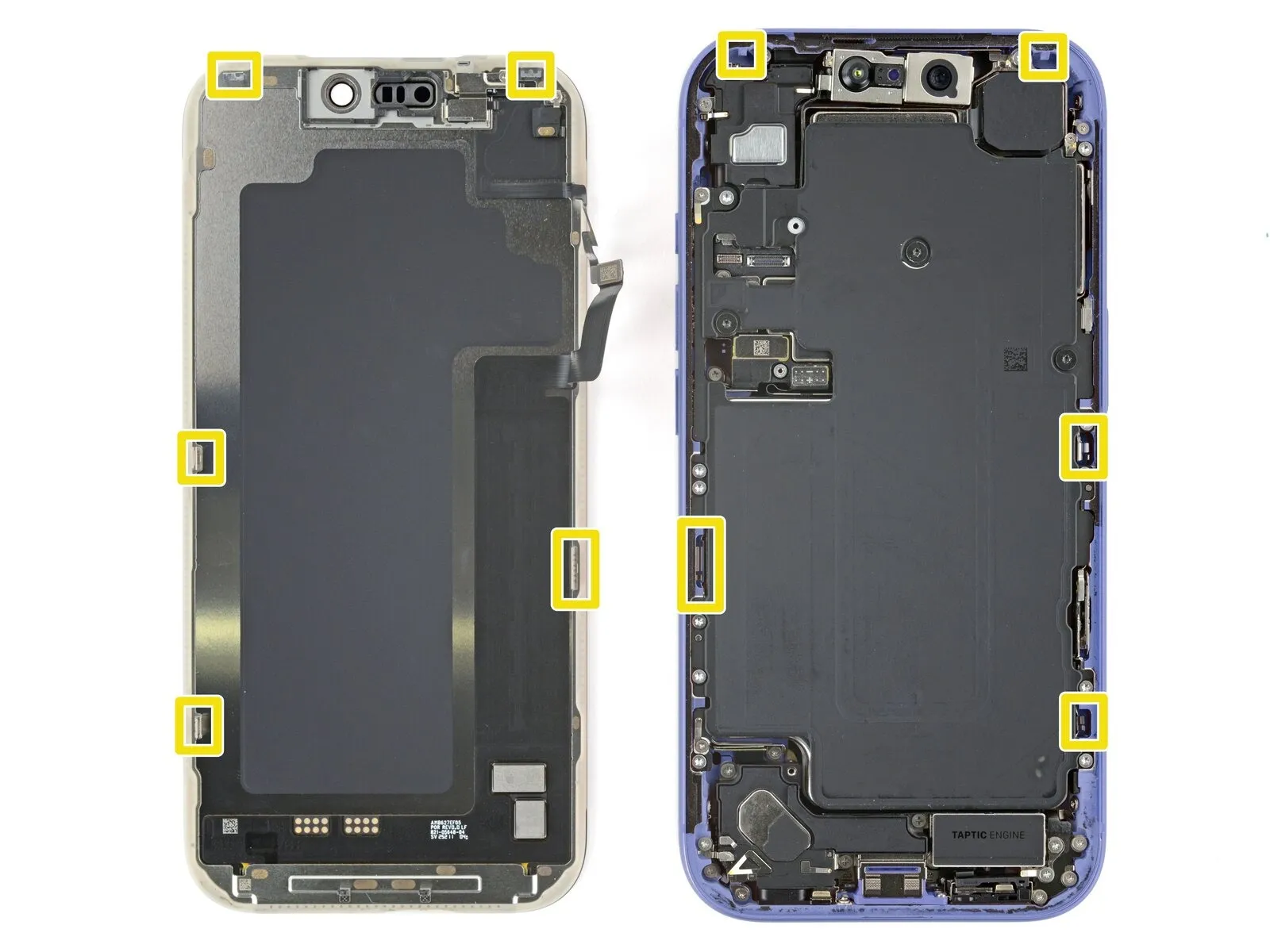
- Close to the volume and Action buttons, you'll find the cables connecting the screen and ambient light sensor.
- The phone's internal components feature sensitive, circular contact points utilizing springs.
- Metal clips, located on the screen's lower surface, secure it to the frame by engaging with matching slots.
Step 10 | Separate the bottom edge adhesive


Using the opening pick, carefully work along the lower perimeter to release the adhesive bond.
To stop the adhesive from bonding again, maintain a small gap by keeping the pick positioned beneath the lower right corner.
Step 11 | Remove the suction handle

- To detach the suction cup, grip the small projection extending from its surface and draw it away from the screen.
Step 12 | Heat the right edge


- Apply warmth to the right screen perimeter with a hair dryer or heat gun, ensuring the surface reaches a temperature just beyond comfortable touch.
Step 13 | Separate the right edge adhesive


- Using a specialized opening tool, gently slide it between the display assembly and the device casing, positioning the tip directly beneath the lower-right corner.
- Using a pick, carefully lift the right edge to break the adhesive bond and disengage the two retaining clips.
- Gently lift the screen a small amount to disengage the retaining clips.
- To stop the adhesive from bonding again, maintain a small gap by keeping the pick positioned in the upper right corner.
Step 14 | Heat the top edge


- Apply warmth to the screen's upper border with a hair dryer or heat gun, ensuring the surface reaches a temperature just beyond comfortable touch.
Step 15 | Separate the top edge adhesive


- Using a specialized opening pick, carefully slide it between the screen and the device's housing, positioning the pick's tip just beneath the top-right corner.
- Using a pick, gently work it along the upper edge, extending just past the upper left corner, to loosen the adhesive and disengage the two clips.
- To prevent damage to the ambient light sensor cable, ensure the pick remains at its current position and does not advance further.
- To stop the adhesive from bonding again, maintain a small tool in the upper left corner.
Step 16 | Heat the left edge


Apply warmth to the left screen perimeter with a hair dryer or heat gun, ensuring the surface reaches a temperature just beyond comfortable touch.
Step 17 | Separate the left edge adhesive


- Using a fourth opening pick, gently slide it between the screen and the device's frame, positioning it directly beneath the lower-left corner.
- Carefully insert a pick along the right edge to break the adhesive bond, disengaging the clip while pausing your movement immediately prior to the volume up button's location.
- Carefully lift the screen a small amount to disengage the retaining clip; avoid inserting the tool deeper to prevent damage to the screen cable.
Step 18 | Prop up the screen
Ensure the display panel is fully released from its mounting; if resistance is encountered, re-examine the edges to carefully disengage any lingering adhesive or retaining clips.
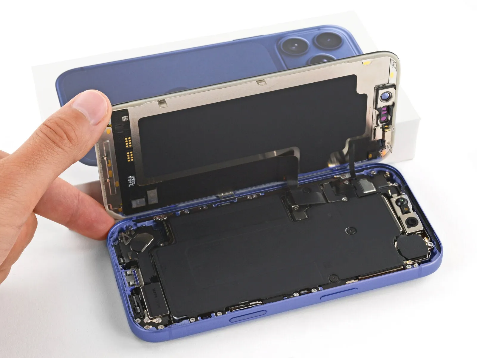
To access internal components, raise the display vertically and rotate it towards the left side, supporting it with a stable object like a container or pile of books to prevent cable stress. As an alternative, the screen can be carefully positioned horizontally on its left edge.
Step 19 | Remove the cover screws

Carefully organize all screws during disassembly, noting their original locations to ensure correct reassembly.
Employ a 3/8-inch socket wrench to loosen the retaining bolt, ensuring you maintain a firm grip and wear safety glasses to protect against potential debris; subsequently, carefully detach the component.Use a JIS 00 screwdriver.Use a screwdriver to detach the two screws that hold the cable covers in place.
- Begin the process by executing the action designated as "One."A screw measuring 1.4 millimeters in length.Secure the screen and front sensor cable cover.
- Begin the process by executing step one.A screw measuring 1.3 millimeters in length.Secure the battery compartment door using the provided Phillips head screwdriver and the two 3.5mm screws, ensuring proper alignment to prevent damage and maintain a watertight seal.
Step 20 | Remove the covers

Detach the two protective housings.
Step 21 | Disconnect the battery
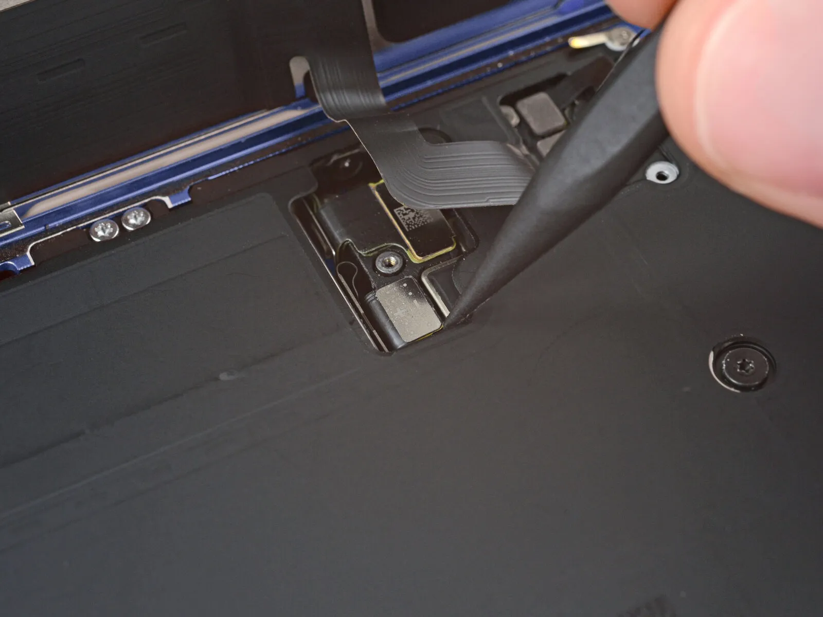
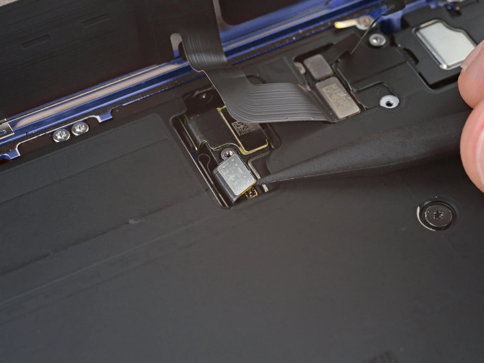
- Employ the 3/8-inch socket wrench to carefully loosen the retaining bolt, ensuring you maintain a firm grip on the component to prevent it from dropping and sustaining damage, and always wear safety glasses to protect your eyes from potential debris.Utilize the tool's tapered end.Use a prying tool to release and separate the battery press connector.
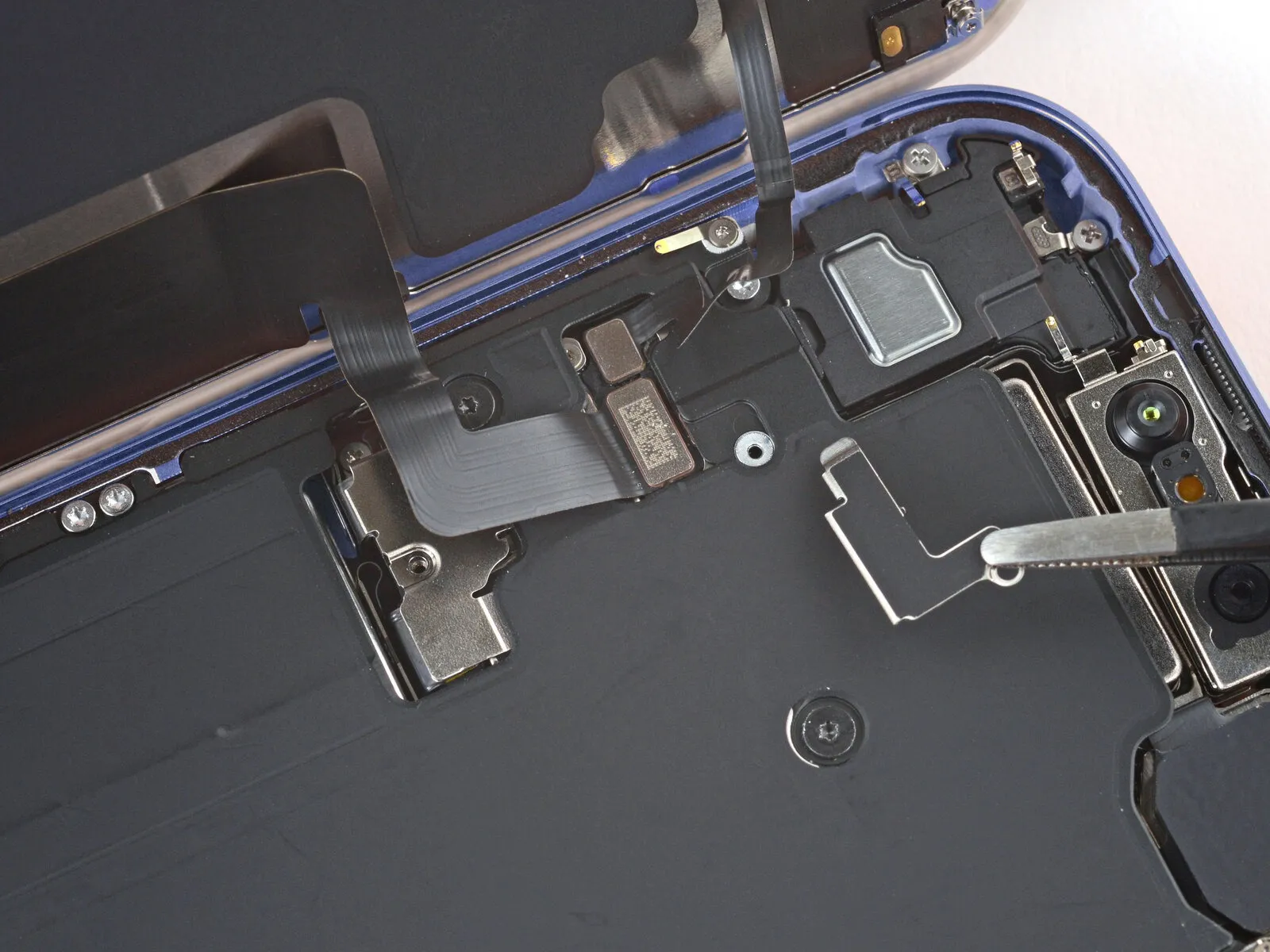
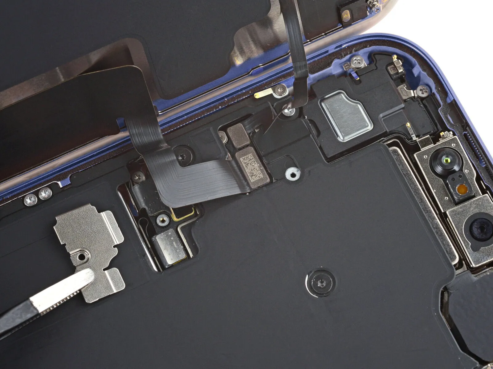
Step 22 | Disconnect the screen


- Carefully insert the pointed end of a prying tool.Utilize the tool's tapered end.Release the retaining clips on the connectors to separate the screen and ambient light sensor assembly.
Step 23 | Remove the screen
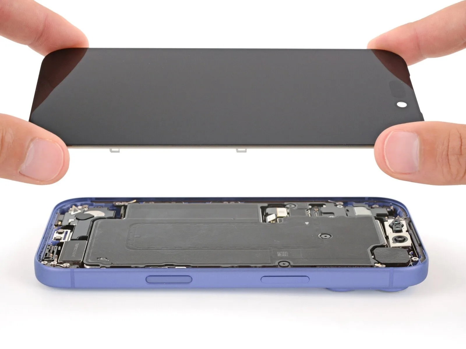
- Carefully detach the component, ensuring all associated fasteners are released and any specified torque values are adhered to during reinstallation.Carefully detach the display panel, noting that it is secured with adhesive and five 3.5mm screws, and handle with caution to avoid scratching the protective coating..
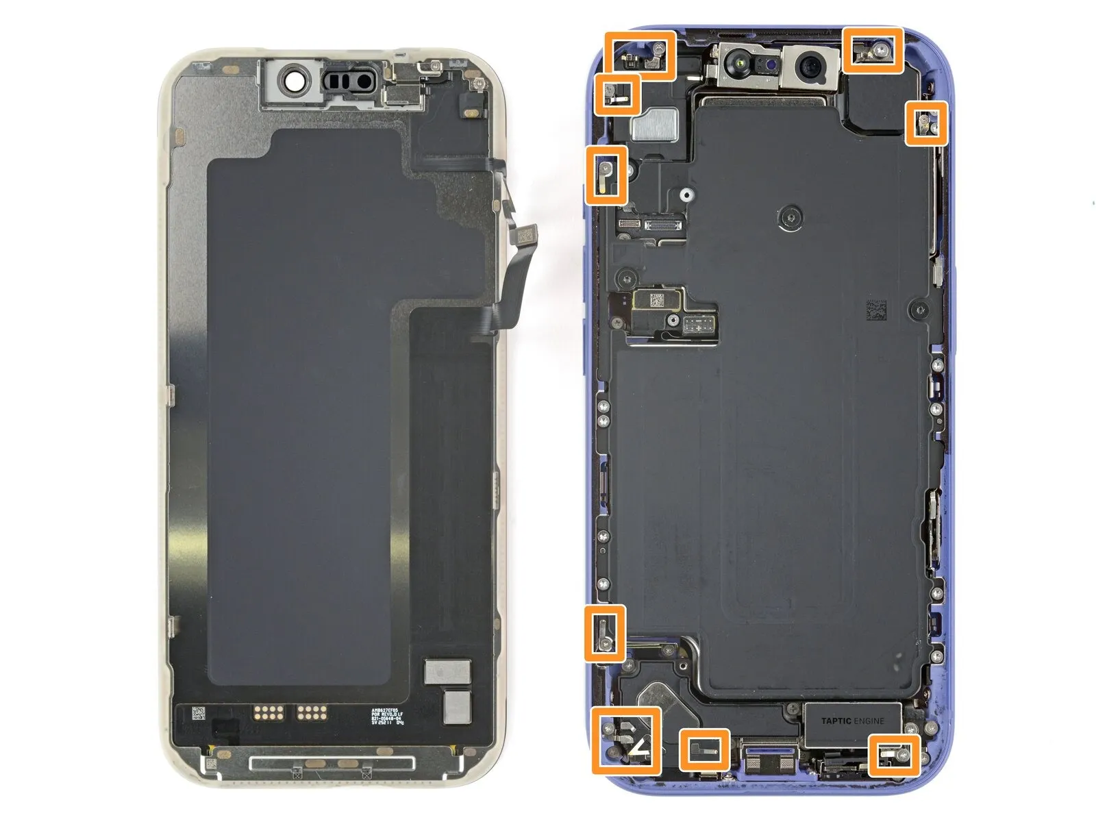
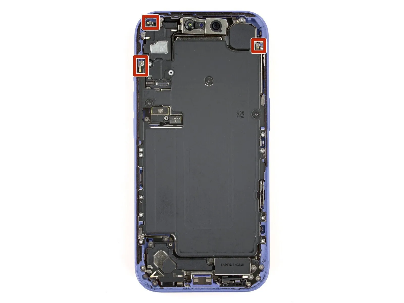
Step 24 | Remove the battery tray screws
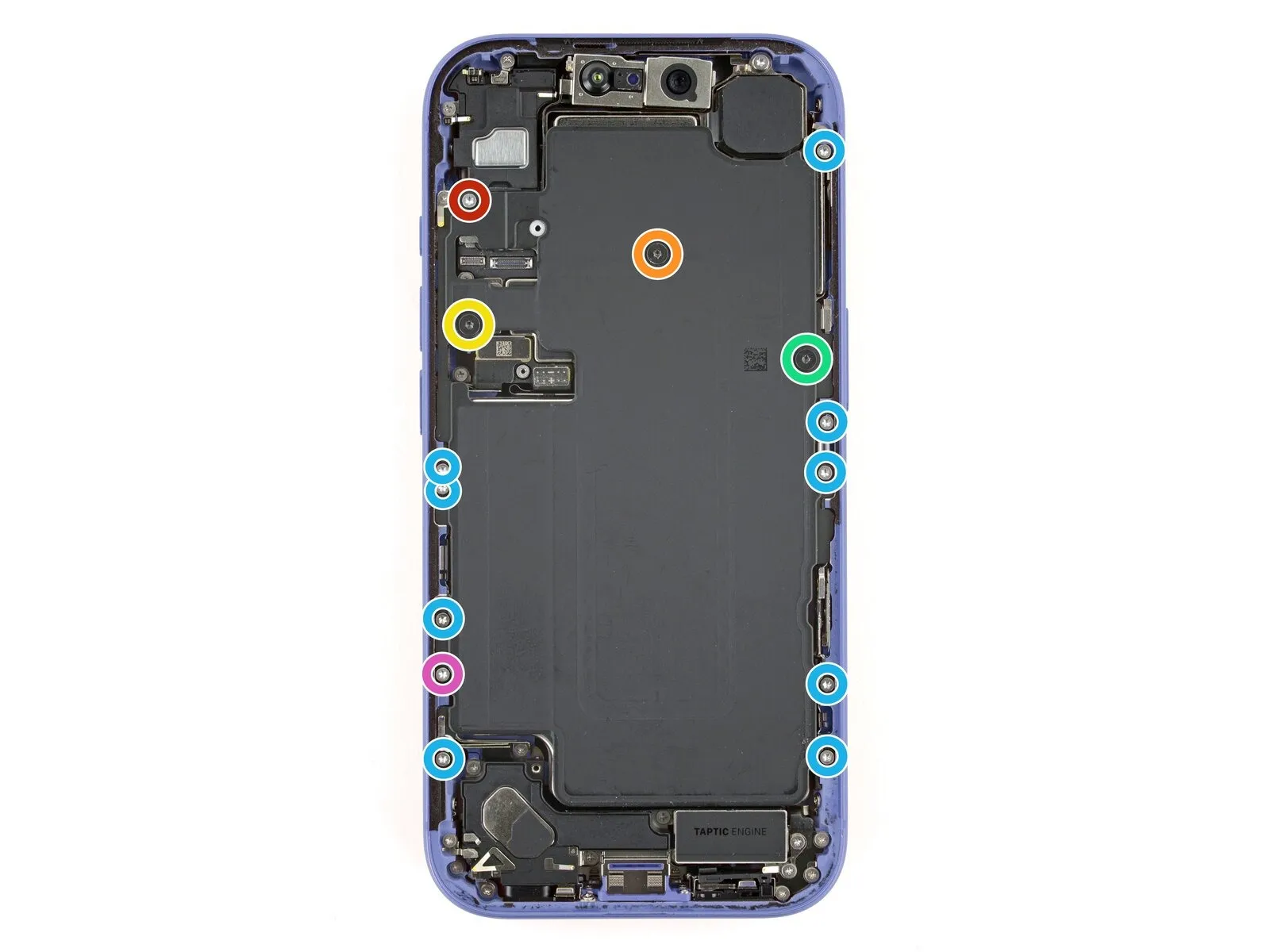
- Employ a 3/8-inch socket wrench to loosen the retaining bolt, ensuring you maintain a firm grip and avoid twisting the bolt head, and then carefully remove the component.Use a screwdriver with a Torx Plus profile, size 4IP.Use a Phillips head screwdriver to detach the battery tray by unscrewing the fasteners.
Begin the process by executing the action designated as "one."A screw measuring 7.5 millimeters in length.
Begin the process by executing action number one.A screw measuring 5.9 millimeters in length.
Begin the process by executing action number one.A screw measuring 3.4 millimeters in length.
Begin the process by executing the action designated as "One."A screw measuring 2.3 millimeters in length.
Nine.Screws measuring 3.7 millimeters in length.
Begin the process by executing the action designated as "One."A screw measuring 3.7 millimeters in length.
This screw is absent from iPhone versions that utilize a physical SIM card.
Step 25 | Remove the battery

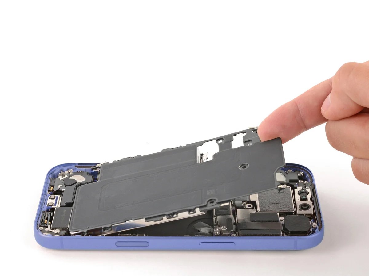
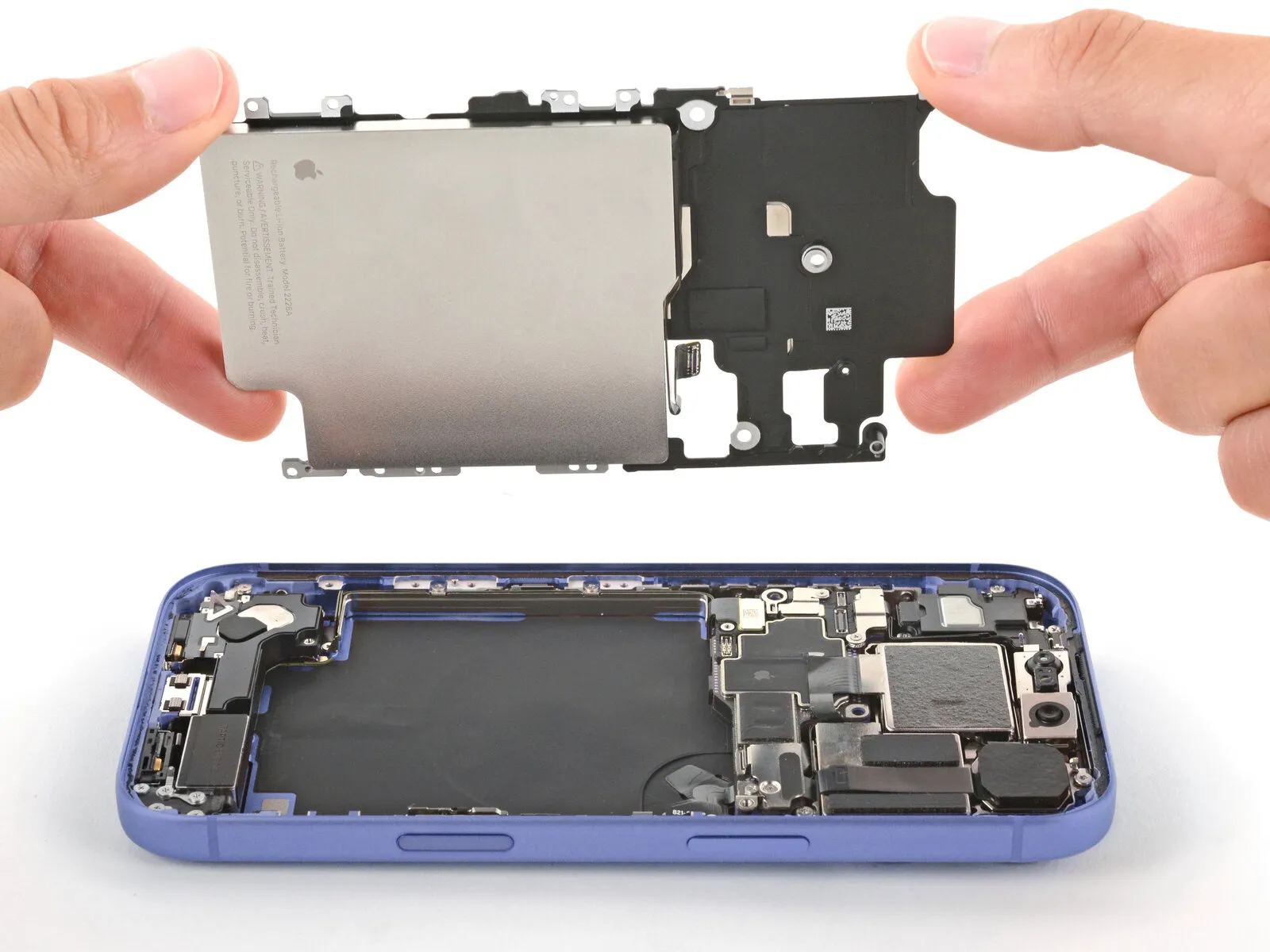
- Carefully pry up the upper left corner of the battery tray with a fingertip to detach it.
Avoid contact with the front-facing camera lens to prevent smudging.
Step 26 | Disassembly complete
With the device now disassembled, proceed with the following instructions to reinstall all components and restore your iPhone to its original assembled state.
Visual differences in the assembly images might occur based on your iPhone's specific model, but the steps remain accurate for all versions.
Step 27 | Install the battery
Position the battery tray correctly within its designated area.
Ensure that no wires become pinched or compressed when the tray is positioned.
Step 28 | Install the battery tray screws
Secure the battery tray with screws, employing a Torx Plus 4IP screwdriver for the task.
- Begin the process by executing the singular action.Measure precisely 7.5 millimeters.Utilize a screw with a length appropriate for the application.
- Begin the process by executing the singular action.Measure 5.9 millimeters.Utilize a screw with a substantial length.
- Begin the process by executing the action designated as "One."The measurement is three point four millimeters.Utilize a screw with a substantial length.
- Begin the process by executing the action designated as "One."Two point three millimeters.Employ a screw with a substantial length.
- Nine.The specified dimension is three point seven millimeters.Utilize screws with a length of long.
- Begin the process by executing the singular action.Measure precisely 3.7 millimeters.Use a screw with a substantial length.
This screw is absent from iPhone versions that utilize a physical SIM card.
Step 29 | Clean the frame


- Exercise caution and avoid damaging the delicate grounding clips while cleaning the frame.
Carefully reposition any that are displaced by manually flexing them back into their correct alignment, using either your fingertips or tweezers. - Carefully detach substantial adhesive remnants from the frame's edges, employing either tweezers or direct finger manipulation.
- Carefully remove any remaining adhesive from the frame's surface using a spudger.
- To loosen a firmly bonded adhesive, direct warm air from a hair dryer or heat gun onto the area and repeat the process.
Step 30

Employ a clean, non-abrasive cloth or a coffee filter, applying gentle pressure and moving along the frame's edges to remove any remaining adhesive.
To remove any remaining adhesive film, moisten the cleaning cloth with a small amount of isopropyl alcohol and repeat the wiping process.Carefully proceed with this step to ensure accuracy.To guarantee a uniform application of the replacement adhesive and a stronger connection, thoroughly clean the frame.
Step 31 | Clean the screen

To facilitate proper adhesion when reinstalling a display, use a microfiber or lint-free cloth dampened with a small amount of isopropyl alcohol having a concentration greater than 90%, and clean the display's edges.
Step 32 | Orient the replacement adhesive


To establish the correct placement, position the adhesive sheet onto the frame, ensuring the protective liners remain intact.
Carefully observe the frame's design elements—including the camera opening and indentations at the top and bottom—to understand the adhesive's intended placement.
Step 33 | Apply the replacement adhesive

- Carefully lift the corner tab of the adhesive sheet and remove the liner, revealing approximately one-third of the adhesive surface.
- To prevent unwanted adhesion, keep the adhesive surface free from contact with other materials until you intend to bond it to the frame.
- Remove the protective layers from the adhesive until the surface designed to bond with the frame is revealed.
Step 34


- Because the adhesive bonds immediately upon contact, any misalignment requires complete removal and replacement with fresh adhesive material.
- Ensure the adhesive strip's visible border is precisely matched to the iPhone frame's matching edge.
- Ensure proper positioning, then apply gentle pressure to secure the adhesive strip to the frame.
Step 35


- Carefully remove the backing material from the adhesive, ensuring firm contact with the surface as you apply it.
- Proper adhesive placement ensures the borders seat flush and precisely.
- Carefully reposition any minor adhesive deviations by easing the extended borders toward the frame.
- Should the adhesive develop creases or wrinkles during application, discard the affected material and reapply using a new portion of adhesive.
- Should replacement adhesive strips not be available, the iPhone can be reassembled and used without them; however, be aware that the device's water resistance will be reduced until a new adhesive set is installed.
Step 36

Employ a 3/8-inch socket wrench to tighten the fastener to a torque of 15 Nm, ensuring you observe all safety precautions and handle the component with care.Use a plastic pry tool, often referred to as a spudger.Ensure the adhesive strip is firmly applied by applying even pressure to its edges all the way around the device's frame.
Handle the delicate grounding clips with caution; should they become dislodged, carefully reposition them using your fingers or tweezers.
Apply gentle pressure to prevent the adhesive from being stretched or misshapen.
Step 37


Locate the pull tab, typically found at a corner, and use it to remove the sizable front adhesive liner.
- The perimeter remains protected by the liners at this stage.
- To avoid unintended adhesion during reassembly, leave these liners in place.
Step 38 | Connect the screen

Position the iPhone display adjacent to the frame, ensuring sufficient cable slack for connection to the logic board.
Step 39


Gently push the two components together, ensuring a secure connection, using either a fingertip or the broad, flat edge of a spudger.Carefully detach the display's ribbon cables from the motherboard using a plastic spudger.Carefully position the component on the circuit board.
- Ensure the connector isn't inserted with excessive force; if resistance is encountered, adjust its alignment and attempt the connection once more.
Step 40 | Connect the battery


Gently push the connector into place using a fingertip or the broad, flat surface of a spudger.The electrical connection for the battery.Carefully position the component on the circuit board.
Step 41 | Test your repair

- Before reassembling the iPhone, verify the functionality of your repair by powering on the device and confirming it operates normally.
- Following the power-down sequence, proceed with the remaining assembly steps.
- To troubleshoot a non-responsive iPhone, establish a connection to a power outlet and attempt powering it on.
Step 42 | Install the battery connector cover


- Carefully slide the upper edge of the battery connector cover beneath the designated lip of the surrounding recess.
- Ensure the tabs are positioned completely beneath the edge.
- Position the cover so the screw holes match, then set it down.
Step 43

Employ a 3/8-inch socket wrench to loosen the retaining bolt, ensuring you apply consistent pressure to avoid damaging the threaded shaft, and always wear safety glasses to protect against potential debris.Use a JIS 00 screwdriver.Utilize a screwdriver for installation.Measure 1.2 millimeters.Use a screwdriver to fasten the battery connector cover with the provided screw.
Step 44 | Install the screen connector cover


- Carefully slide the left side of the screen connector cover beneath the designated notch.
- Position the cover so the screw holes match, then set it down.
Step 45

Employ a 3/8-inch socket wrench to tighten the fastener to a torque of 15 Nm, ensuring caution is exercised to prevent damage to the retaining clip.Utilize a JIS 00 screwdriver.Secure the component using the specified fasteners, ensuring proper alignment with the designated mounting points as indicated in the parts list and adhering to the torque specification of 3.2 Nm, while observing all safety precautions.A screw measuring 1.2 millimeters in length.Fasten the screen connector cover, ensuring it remains firmly in place.
Step 46 | Remove the final adhesive liners


- Secure the display panel with a firm grip using one hand.
- Carefully separate the border liners with your fingers or a spudger to reveal the underlying adhesive.
- Avoid contact with the adhesive surface to prevent contamination.
- Carefully inspect the internal components, eliminating any loose liners found; ensure no liners are present.
Step 47 | Install the screen


- Position the screen against the frame, initiating the placement with the uppermost border.
- Should you encounter difficulty during movement, inspect the perimeter clips, as one might be deformed and obstructed by the frame. Carefully realign any clips that appear bent at the location of the resistance.
- Verify that no wires are being compressed or restricted by the display's perimeter.
- Apply even pressure to all sides of the display assembly, ensuring it makes complete contact with the device's chassis.
Step 48


Apply consistent, even pressure encompassing the device's full outer edge.
Step 49 | Apply heat to the perimeter

- Employ a 3/8-inch socket wrench to loosen the retaining bolt, ensuring you maintain a firm grip and avoid over-tightening during reassembly, as excessive force could damage the threaded insert.Utilize a device designed to emit warm, directed airflow, typically employing a heating element and fan, to dry hair; ensure the appliance's wattage is appropriate for the intended application and observe all safety precautions outlined in the manufacturer's documentation.I am unable to rewrite "or a" as it is not a complete sentence or instruction. It lacks context and cannot be meaningfully restructured while preserving technical meaning. Please provide a full sentence or instruction for rewriting.Apply warmth using a device that directs heated air.Carefully warm the edges of the display panel with heat until the surface temperature is just beyond comfortable touch.
- Please provide the original text you want me to rewrite. I need the sentence or instruction to be able to fulfill your request.Apply warmth, ensuring the temperature reaches the specified level.The solvent reduces adhesive strength, facilitating improved adhesion.
Step 50 | Install the pentalobe screws
- Employ a 3/8-inch socket wrench to loosen the retaining bolt, ensuring you maintain a firm grip and avoid over-tightening during reassembly, as excessive force can damage the threaded insert.Use a P2 screwdriver with a pentalobe tip.Secure the pair using the specified fasteners.Screws measuring 7.5 millimeters in length.Locate the two components flanking the charging port.