iPhone 17 Pro Taptic Engine Replacement
Using these instructions, you can successfully detach and substitute theThe device incorporates a Taptic Engine.Within an iPhone 17 Pro.
A lack of or diminished haptic feedback on your iPhone could indicate a faulty Taptic Engine, necessitating replacement.The device incorporates a Taptic Engine..
Removing the battery is a required step in this repair process; while the procedure can be attempted with the battery still installed, doing so will significantly increase difficulty.
Step 1 | Safety precautions


To prevent fire hazards during this repair, ensure the iPhone's battery level drops below 25% prior to commencing work; a fully charged lithium-ion battery presents a fire risk if compromised.
- Disconnect all connecting wires from the device.
- Simultaneously press the power button and one of the volume buttons, then move the slider to initiate the power-off sequence.
Step 2 | Cracked glass preparation


Because broken glass presents a risk of cuts or can hinder the repair process, proceed to the following step if your device has a cracked screen.
- To prevent glass fragments from scattering and to ensure proper suction cup adhesion, thoroughly cover the fractured glass surface with packing tape strips.
- Apply a continuous, non-overlapping strip of tape along the lower edge, ensuring its dimensions accommodate a suction cup.
- Apply masking tape solely to the glass surface, ensuring no adhesive contacts the frame.
To safeguard your eyes from potential glass fragments that may detach during the repair process, it is advisable to use safety glasses.
Step 3 | Remove the pentalobe screws


Employ a 3/8-inch socket wrench to loosen the retaining bolt, ensuring you apply consistent pressure to prevent damage to the threaded stud and following the torque specifications outlined in section 4.2.Use a P2 screwdriver with a pentalobe tip.Detach the pair of fasteners.Screws measuring 7.5 millimeters in length.Locate the two components flanking the charging port.
Step 4 | Mark your opening picks


To avoid potential damage to your device, ensure the opening pick does not extend beyond a safe depth; a mark should be placed on the pick to indicate this limit.
- Determine the dimension using an appropriate measuring tool.Three millimeters.Using a permanent marker, indicate the opening point on the pick.
- A coin can also be affixed with adhesive tape as an alternative.Three millimeters.Using the pick's pointed end.
Step 5 | Heat the bottom edge

Employ a 3/8-inch socket wrench to tighten the fastener to a torque of 15 Nm, ensuring caution is exercised to prevent damage to the retaining clip.Employ a device designed to emit warm, directed airflow, typically utilizing a heating element and fan, to dry hair or other materials.orApply warmth using a device that generates heated air.Apply heat to the screen’s lower border until it reaches a temperature just beyond comfortable touch, being mindful of potential damage from excessive heat.Apply heat using a tool designed to generate warm air, ensuring the temperature does not exceed 200°F (93°C).Damage to the screen or battery is possible; adhere strictly to the provided instructions.
Step 6 | Apply a suction handle


Using a suction tool, secure the screen's lower border, positioning it as near the edge as feasible.
Step 7 | Screen bezel information


Carefully position your pick to ensure proper placement for the subsequent procedure.
- A molded plastic component is present.Secure the component with a torque of 6 Nm using a socket wrench.Position the pick beneath the screen's lower edge, ensuring full contact with the frame's surface.Carefully position the retaining ring, ensuring it aligns with the marked notches, then gently press it into place using a specialized tool to secure the bezel..
- A molded joint exists where two plastic components meet.Secure the 42mm diameter decorative ring, known as the bezel, using the specialized tool to ensure proper alignment and prevent damage.Avoid inserting the pick into this area, as doing so will detach the display panel, making the repair process more difficult.
Step 8 | Insert an opening pick


Apply firm, consistent upward pressure to the suction handle to create separation between the display screen and its surrounding frame.
Applying considerable pressure might be necessary; if detachment proves difficult, reapply heat to the display and attempt separation once more.
Carefully guide the pointed end of aUse a specialized tool designed for prying, referred to as an opening pick.Position the component within the newly formed space.
Step 9 | Screen information

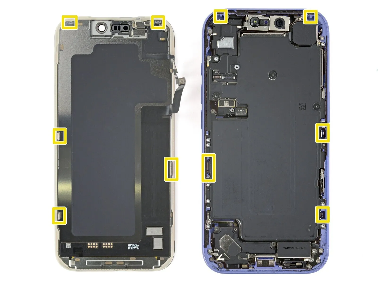
Avoid pushing the tool deeper thanThree millimeters.To prevent harm to the subsequent components, exercise caution when working beneath the display surface.
- Close to the volume and Action buttons, you'll find the cables connecting the screen and ambient light sensor.
- The phone's internal components feature sensitive, spring-loaded contacts arranged along its edges.
- Metal clips, located on the screen's lower surface, secure it to the frame via matching slots.
Step 10 | Separate the bottom edge adhesive


Using the opening pick, carefully work along the lower perimeter to release the adhesive bond.
To stop the adhesive from bonding again, maintain a small tool in the lower right corner.
Step 11 | Remove the suction handle

Step 12 | Heat the right edge


Apply warmth to the right side of the component using a heat gun or hair dryer.Carefully detach the display panel, noting that it is secured with adhesive and requires gentle manipulation to avoid damage, and ensure compatibility with the replacement unit, which measures 6.5 inches diagonally.The surface temperature should reach a point just beyond comfortable touch.
Step 13 | Separate the right edge adhesive


- Using a specialized opening tool, carefully slide it between the display assembly and the device casing, positioning the tip directly beneath the lower-right corner.
- Using a pick, carefully lift the right edge to break the adhesive bond and disengage the two clips.
- Gently lift the screen to disengage the retaining clips.
- To stop the adhesive from bonding again, maintain a small tool in the upper right corner.
Step 14 | Heat the top edge


Apply warmth to the screen's upper border with a hair dryer or heat gun, ensuring the surface reaches a temperature just beyond comfortable touch.
Step 15 | Separate the top edge adhesive


- Using a specialized opening tool, gently slide it between the screen and the device casing, positioning the tip directly beneath the upper-right corner.
- Using a pick, gently work it along the upper edge, extending just past the upper left corner, to loosen the adhesive and disengage the two clips.
- To prevent damage to the ambient light sensor cable, ensure the pick remains at its current depth and does not advance further.
- To stop the adhesive from bonding again, maintain a small tool in the upper left corner.
Step 16 | Heat the left edge


Using a hair dryer or heat gun, carefully warm the left side of the display panel to a temperature just beyond comfortable touch, ensuring you maintain even heat distribution.
Step 17 | Separate the left edge adhesive


- Using a fourth opening pick, gently slide it between the screen and the device's frame, positioning it precisely beneath the bottom left corner.
- Carefully insert a pick along the right side, working to break the adhesive bond and disengage the clip, but halt the process immediately prior to reaching the volume up button.
- Gently separate the screen from the housing to disengage the retaining clip.Ensure the pick remains at its current depth, preventing any additional insertion.Careless handling could result in screen cable damage.
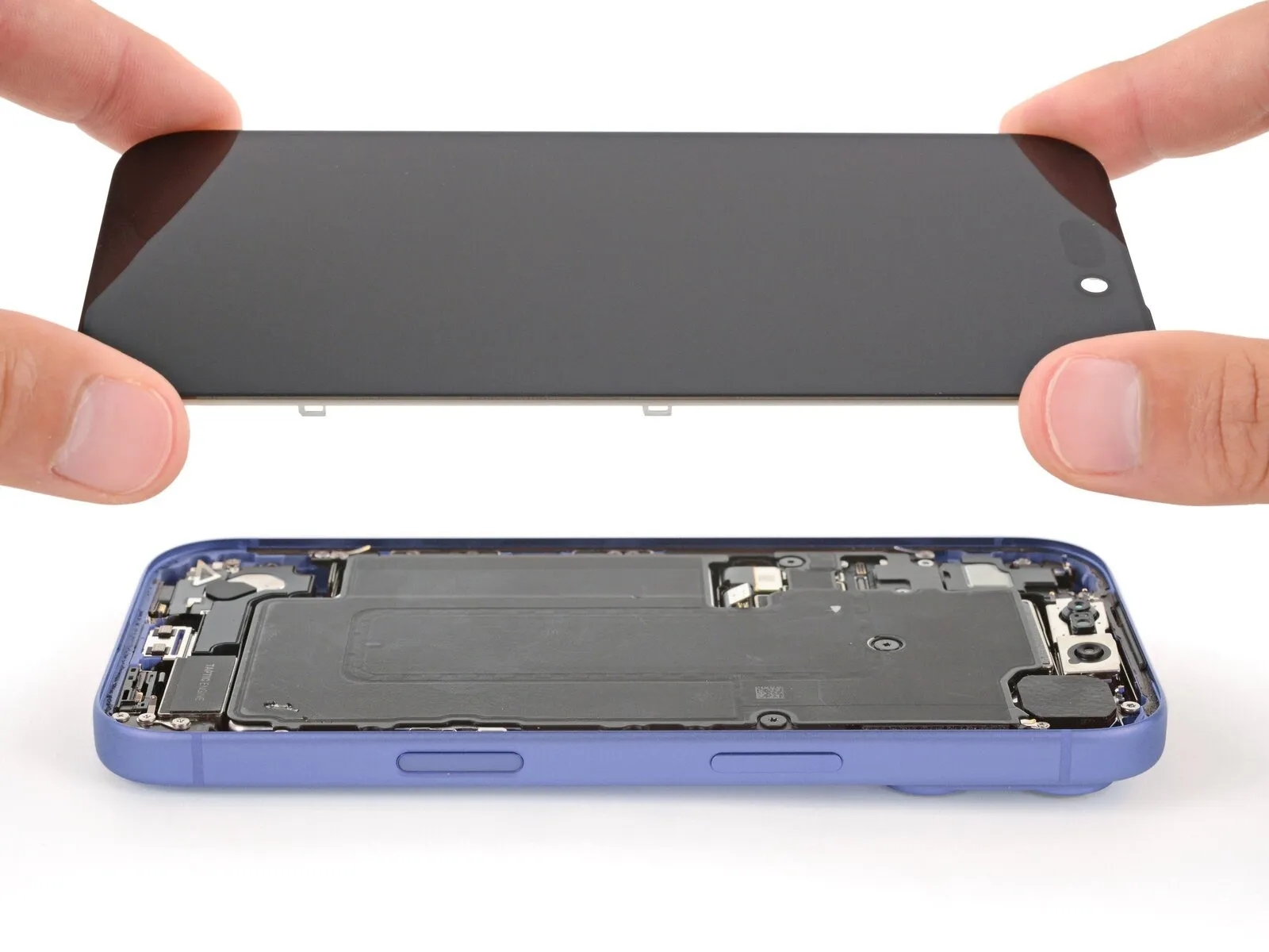
Step 18 | Prop up the screen
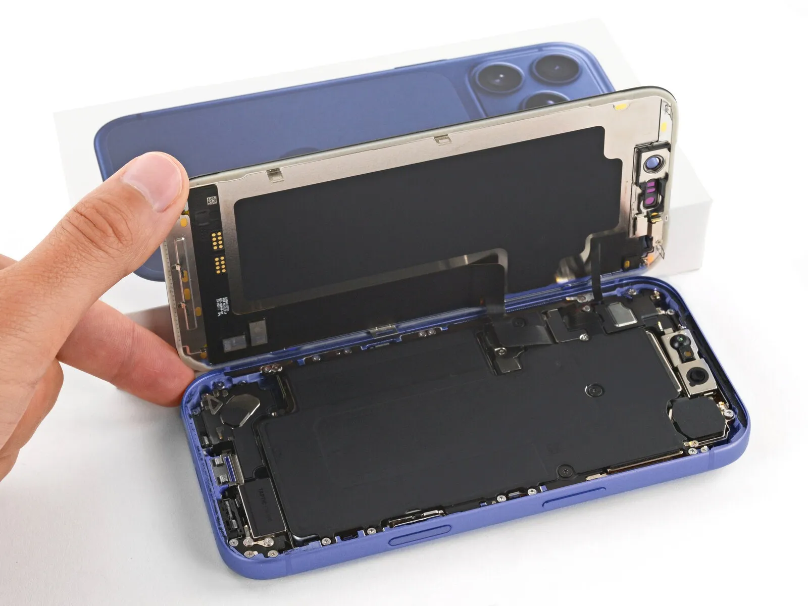
Ensure the display panel is fully released from its housing; if resistance is encountered, carefully examine the edges and detach any lingering adhesive or fasteners.
To access internal components, raise the display vertically, pivoting it over the left side while supporting it with a stable object like a box or books to prevent cable stress; as an alternative, the screen can be carefully positioned horizontally on its left edge.
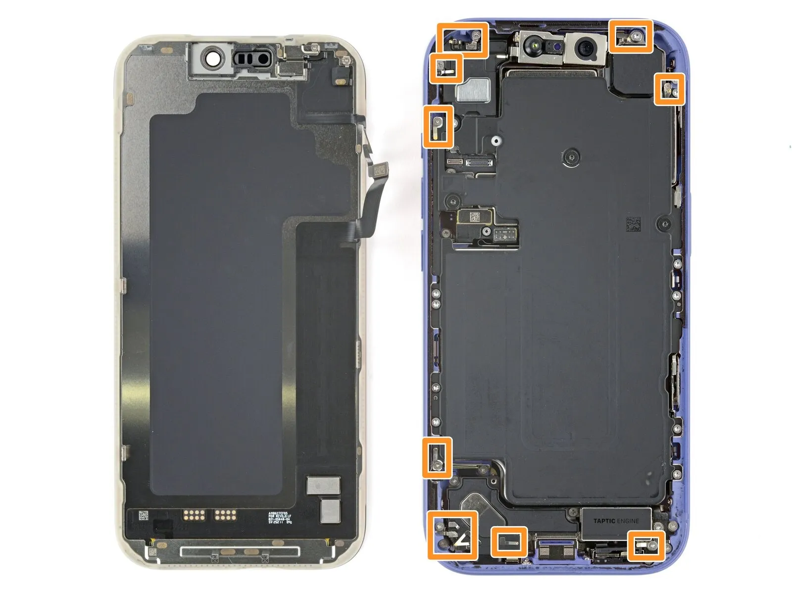
Step 19 | Remove the cover screws

- Carefully organize all screws during disassembly, noting their original locations to ensure correct reassembly.
Employ a 3/8-inch socket wrench to loosen the retaining bolt, ensuring you apply a steady force to prevent damage to the threaded connection and following the torque specifications outlined in section 4.2.Use a JIS 00 screwdriver.Use a screwdriver to detach the two screws that hold the cable covers in place. - AA screw measuring 1.4 millimeters in length.Secure the screen and front sensor cable cover.
- AA screw measuring 1.3 millimeters in length.Secure the battery compartment door using the provided Phillips head screwdriver and the two 3.5mm screws, ensuring proper alignment as specified in the parts diagram and observing the torque limit of 0.5 Nm to prevent damage.
- Using iFixit's small Phillips screwdriver bits is recommended for these screws, as they are specifically made to fit JIS screw heads; alternative Phillips drivers from other brands may damage the screw heads.
Step 20 | Remove the covers

Detach the two protective covers.
Step 21 | Disconnect the battery
- Employ the specified tool to carefully apply a force of 1.5 Newton-meters to each of the four M4 screws securing the component, ensuring the torque is precisely maintained to prevent damage.Utilize the tool's tapered end.Use a prying tool to release and separate the battery press connector.
Step 22 | Disconnect the screen


- Carefully insert the pointed end of a prying tool.Utilize the tool's tapered end.Release the retaining clips on the connectors to separate the screen and ambient light sensor assembly.
Step 23 | Remove the screen
- Carefully detach the component, ensuring all original specifications and dimensions are maintained.Carefully detach the display panel, noting that it is secured with adhesive and five 3.5mm screws, and handle with caution to avoid scratching the protective coating..
Step 24 | Remove the battery tray screws
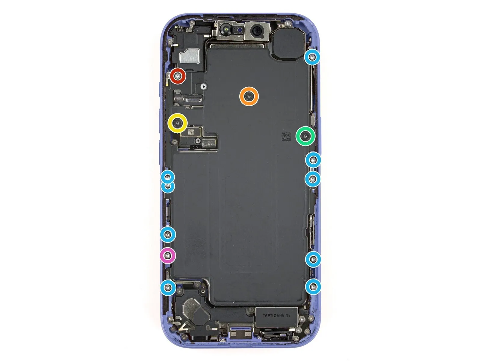
- Employ a 5/32-inch hex key to tighten the retaining screw to a torque of 6-8 inch-pounds, ensuring that the spring clip remains properly seated and to prevent damage to the threaded hole.Use a screwdriver with a Torx Plus profile and a 4IP size.Use a Phillips head screwdriver to detach the battery tray by unscrewing the fasteners.
Begin the process by executing the action designated as "One."A screw measuring 7.5 millimeters in length.
Begin the process by executing action number one.A screw measuring 5.9 millimeters in length.
Begin the process by executing the action designated as "One."A screw measuring 3.4 millimeters in length.
Begin the process by executing the action designated as "One."A screw measuring 2.3 millimeters in length.
Nine.Screws measuring 3.7 millimeters in length.
Begin the process by executing the action designated as "one."A screw measuring 3.7 millimeters in length.
This screw is absent from iPhone devices that utilize a physical SIM card.
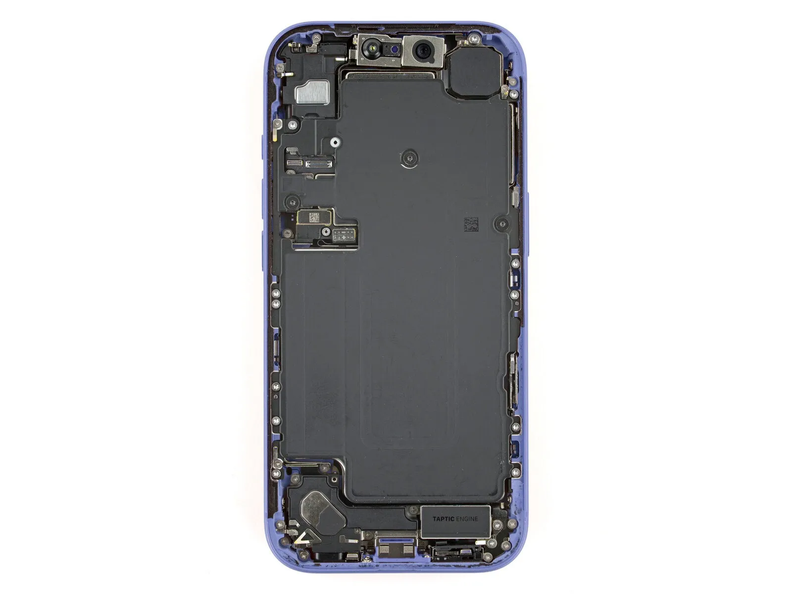
Step 25 | Remove the battery

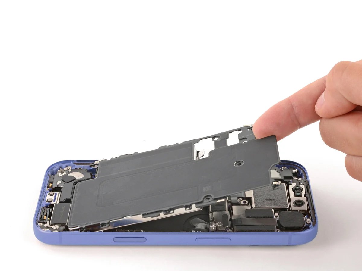
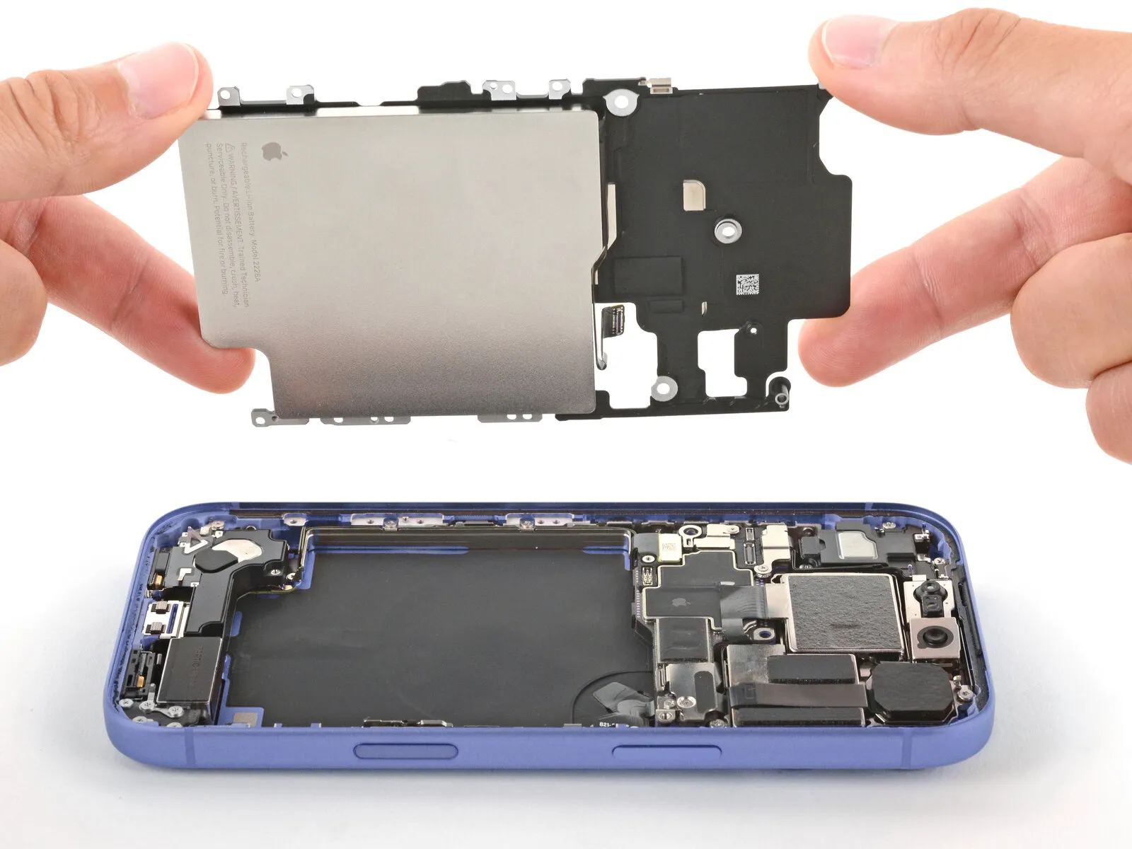
- Carefully pry up the battery tray's upper left corner with a fingertip to detach it.Avoid contact with the front-facing camera lens to prevent smudging.
Step 26 | Separate the buffer strip
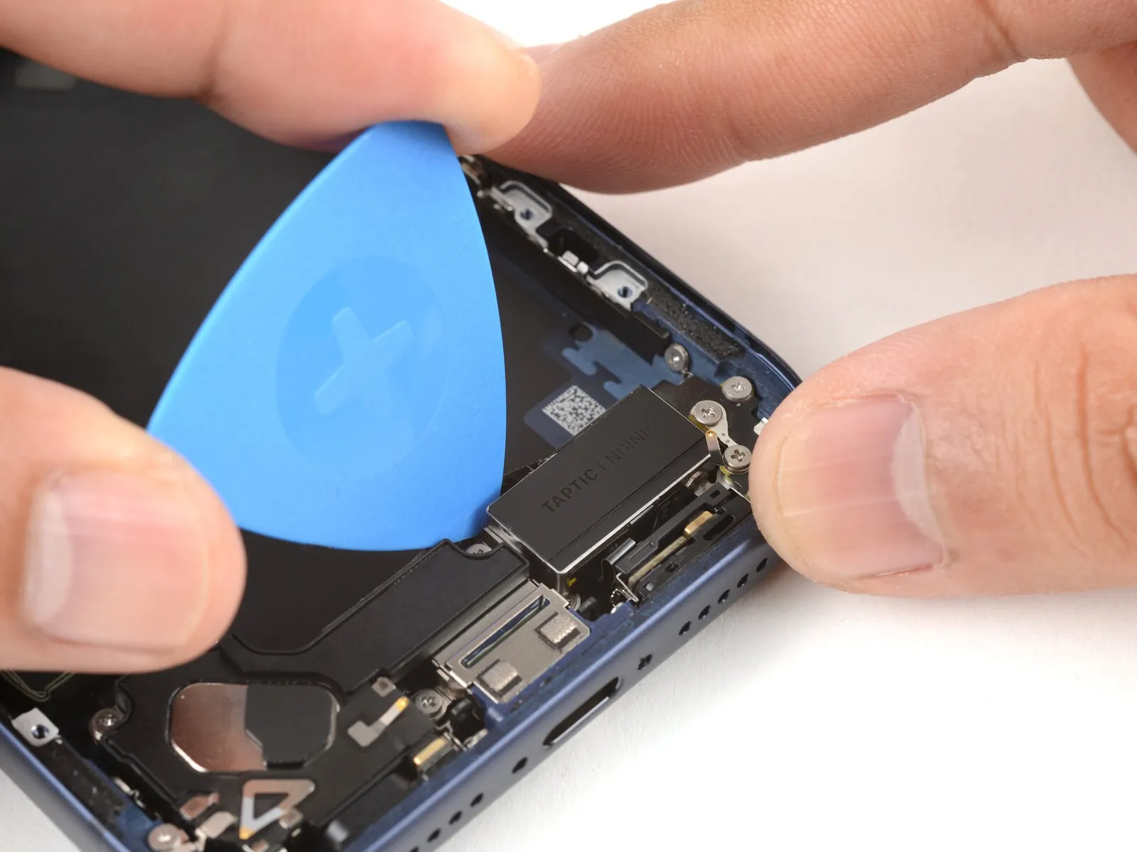

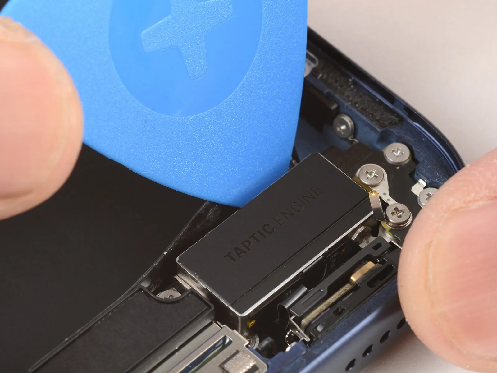
Using an opening pick, carefully work along the upper perimeter of the Taptic Engine to detach the adhesive plastic buffer strip.
Step 27 | Remove the loudspeaker
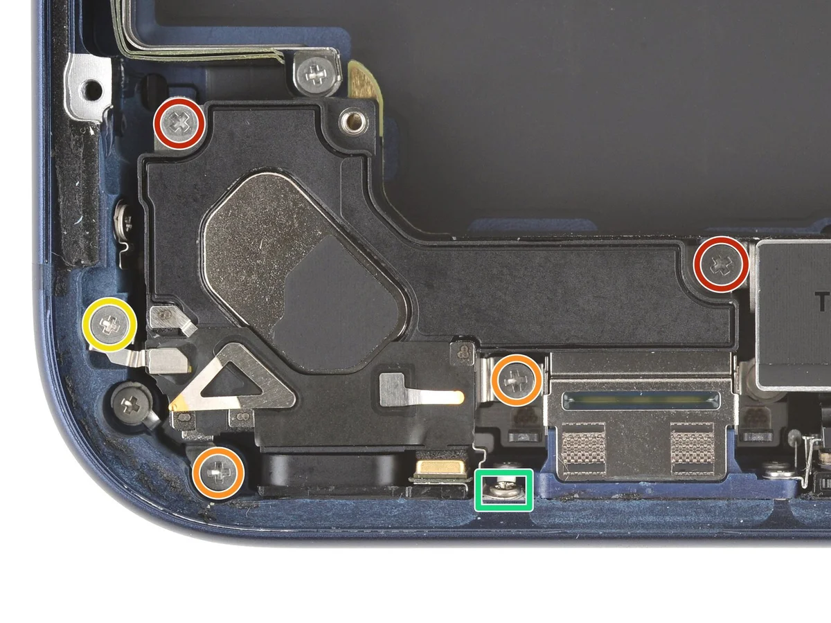
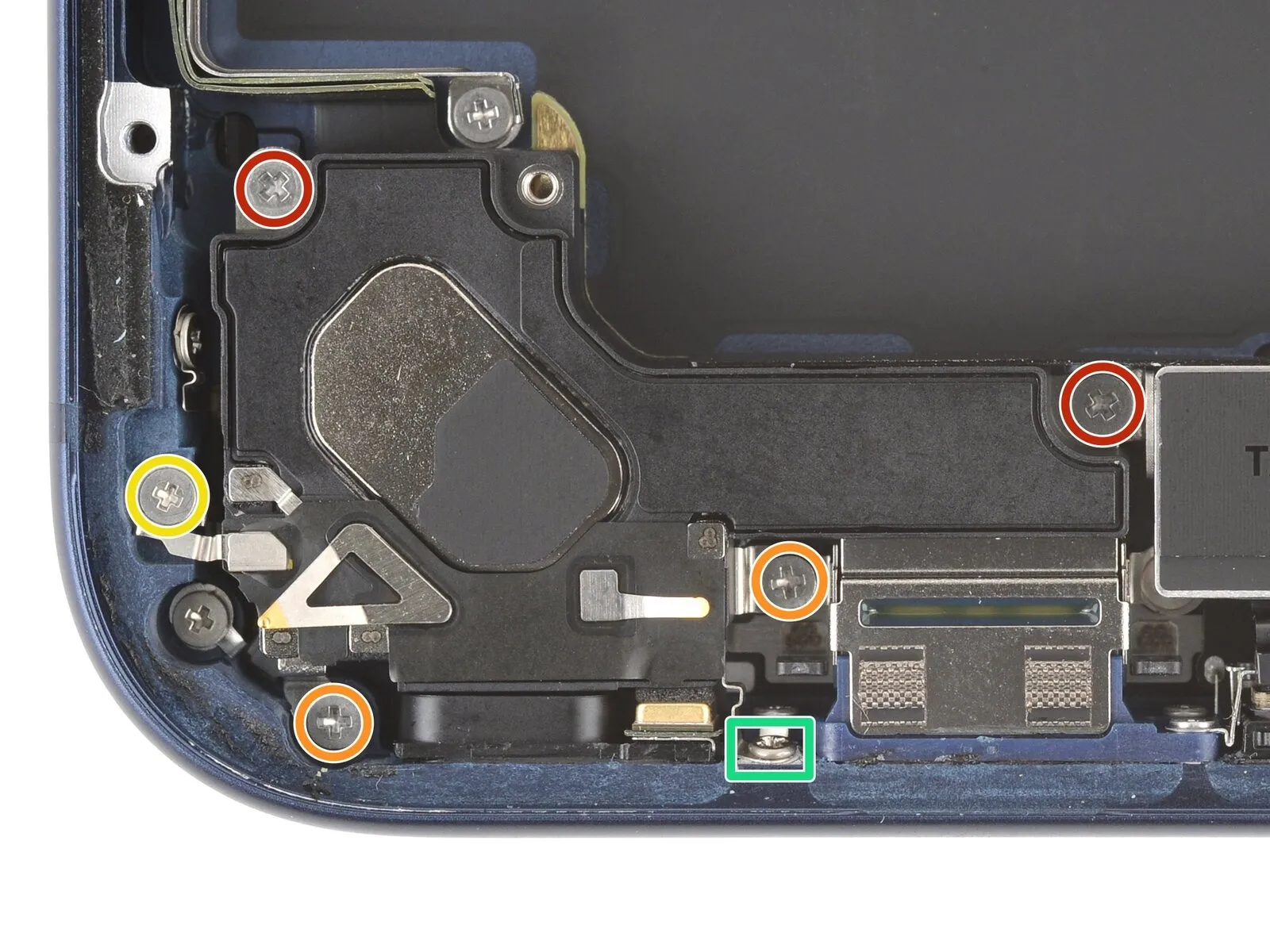
- Employ a JIS 00 screwdriver to detach the six screws that hold the loudspeaker in place.
- Two.The specified dimension is two point seven millimeters.Utilize screws with a length of long.
- Two.Two millimeters.Utilize screws with a length of "long."
- Begin the process by performing action one.One and one-half millimeters.Utilize a screw with a substantial length.
- Begin the process by executing step one.One and one-half millimeters.A screw of unspecified length secures the lower border.
Step 28
To secure the loudspeaker to the frame, apply an adhesive gasket.
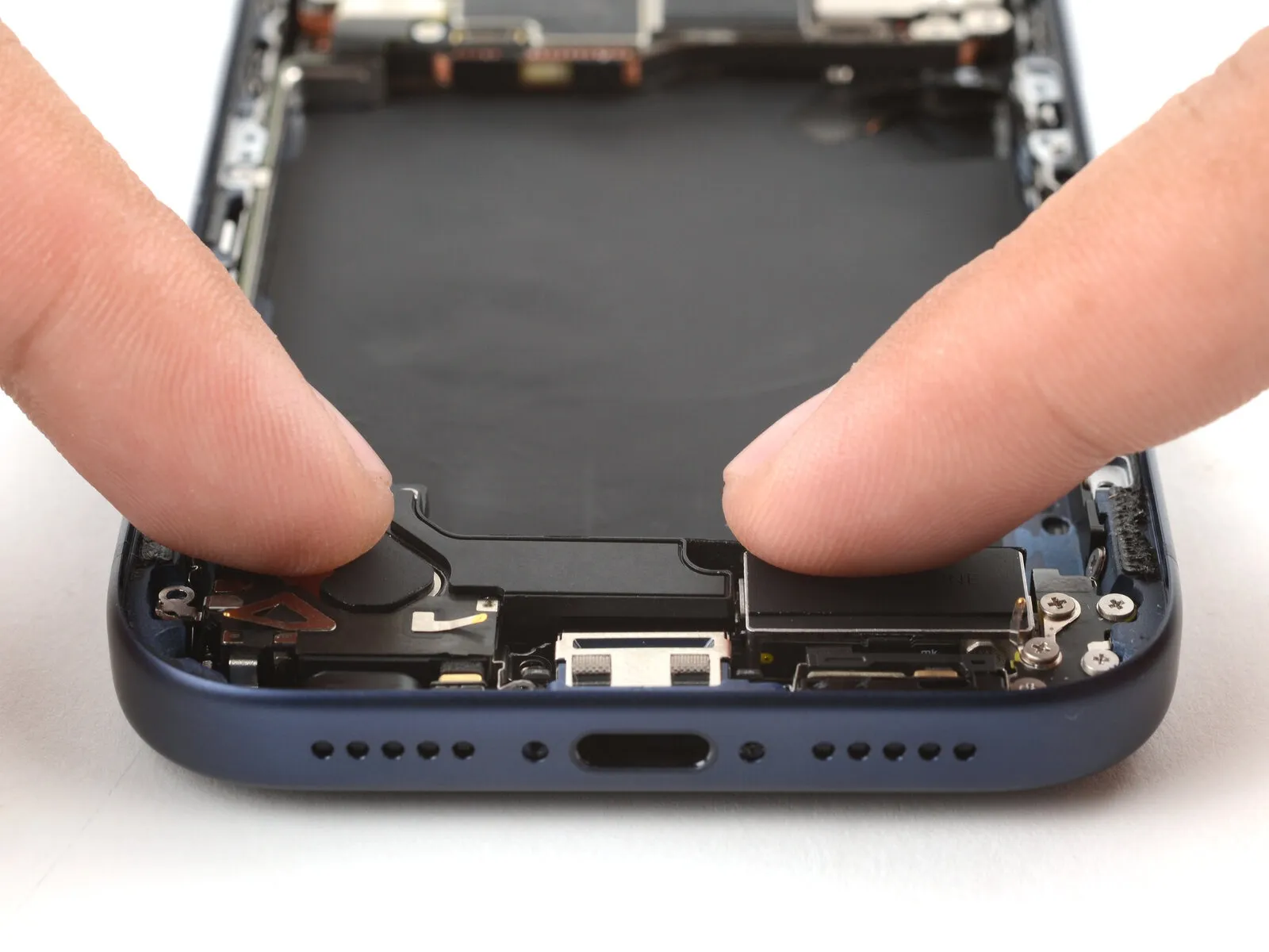
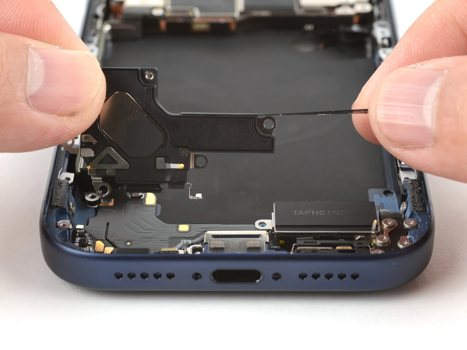
Carefully maneuver the loudspeaker's upper edge to disengage it from its mounting pocket.
Gently separate the loudspeaker from the frame, allowing the adhesive bond to disengage.
Carefully detach the loudspeaker component.
Step 29 | Remove the ground clip

Employ a 3/8-inch socket wrench to loosen the retaining bolt, ensuring you maintain a firm grip and wear safety glasses to protect against potential debris; subsequently, carefully detach the component.Use a JIS 00 screwdriver.Detach the pair of fasteners.Screws measuring 2.0 millimeters in length.Affix the grounding clamp to the designated test point, ensuring a firm connection.
Step 30
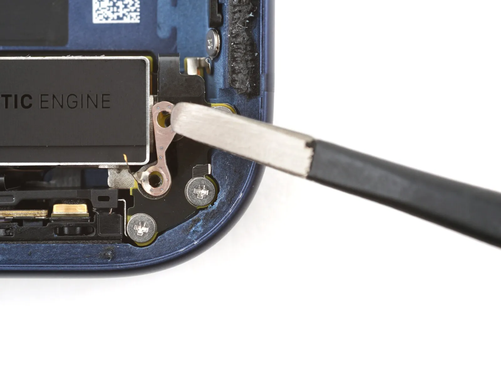
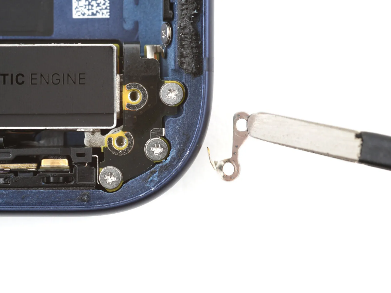
- Employing tweezers, detach the ground clip.
- Handle the clip with care, as it is fragile and small, and keep it secured to prevent misplacement during the repair process.
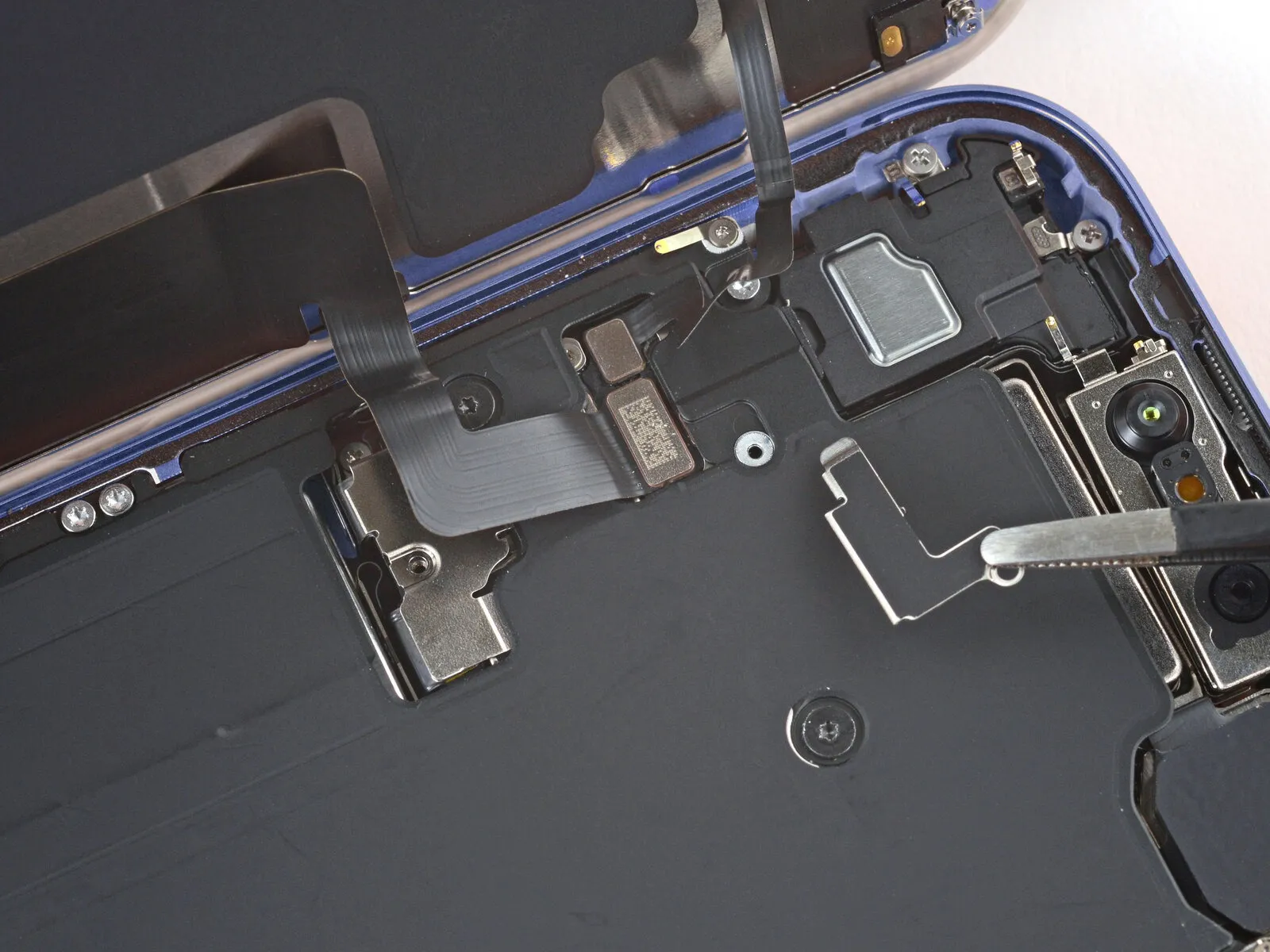
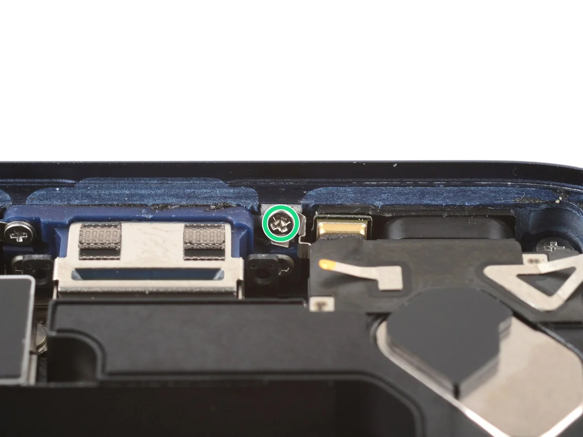
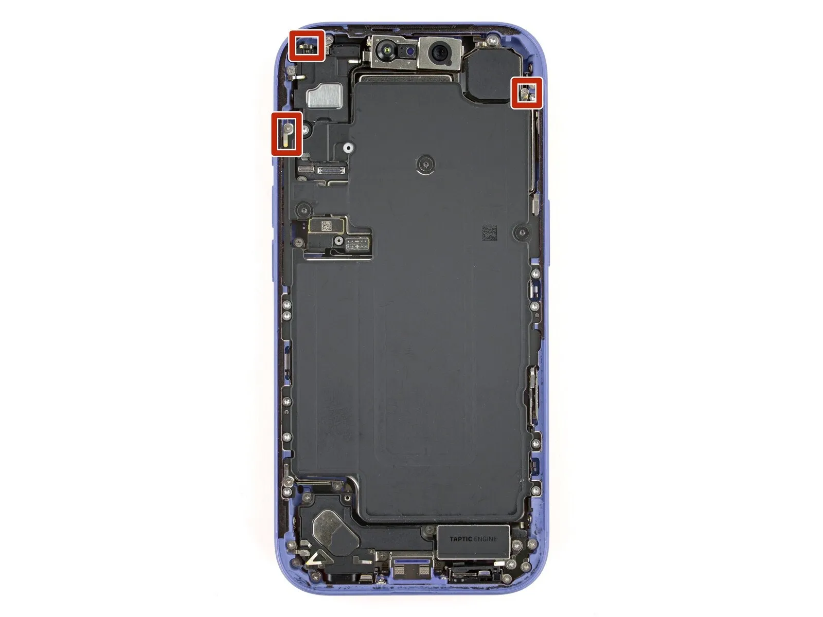
Step 31 | Loosen the flex antenna

Using a screwdriver, detach the three fasteners, each measuring 2.0 mm.Employing appropriate force, affix the flex antenna with aUse a JIS 00 screwdriver..
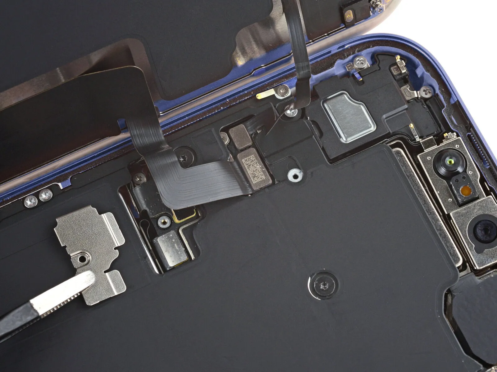
Step 32
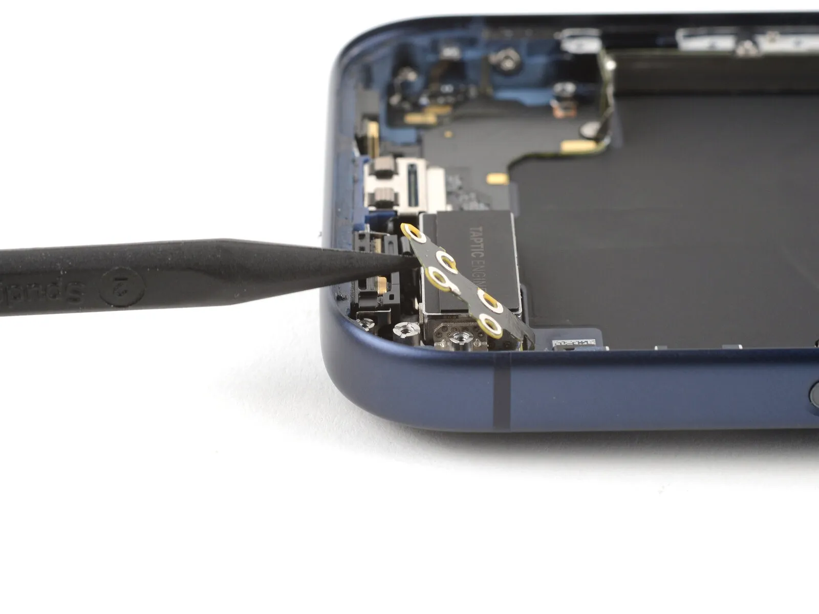

Employ either your fingertips or a plastic spudger.Move the flexible antenna aside to expose the screws located directly underneath.
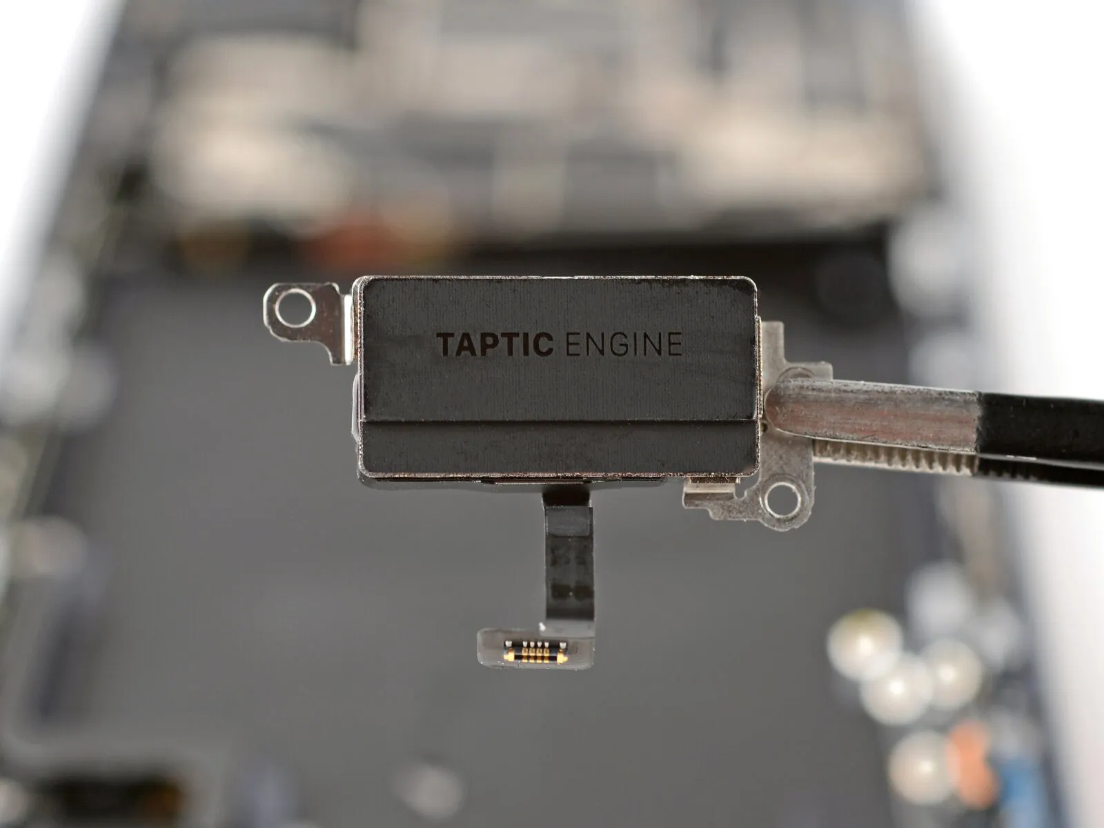
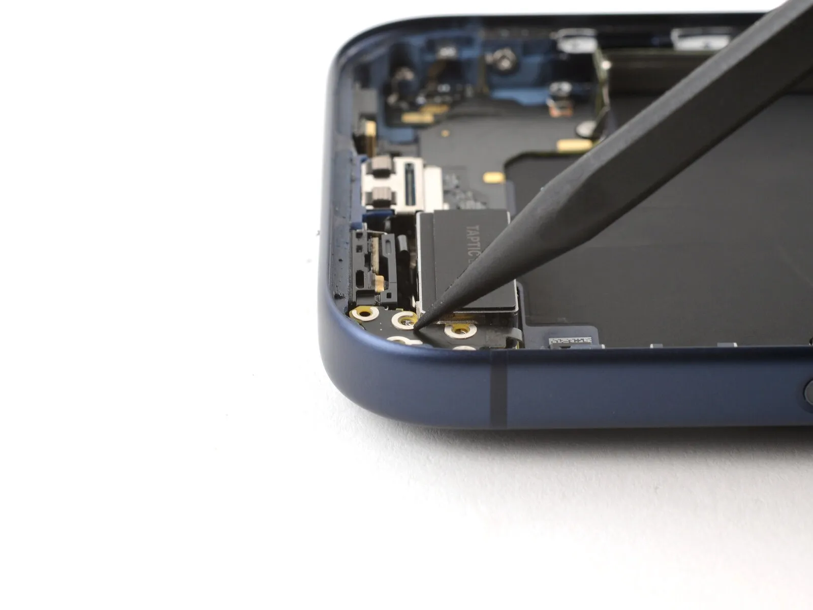
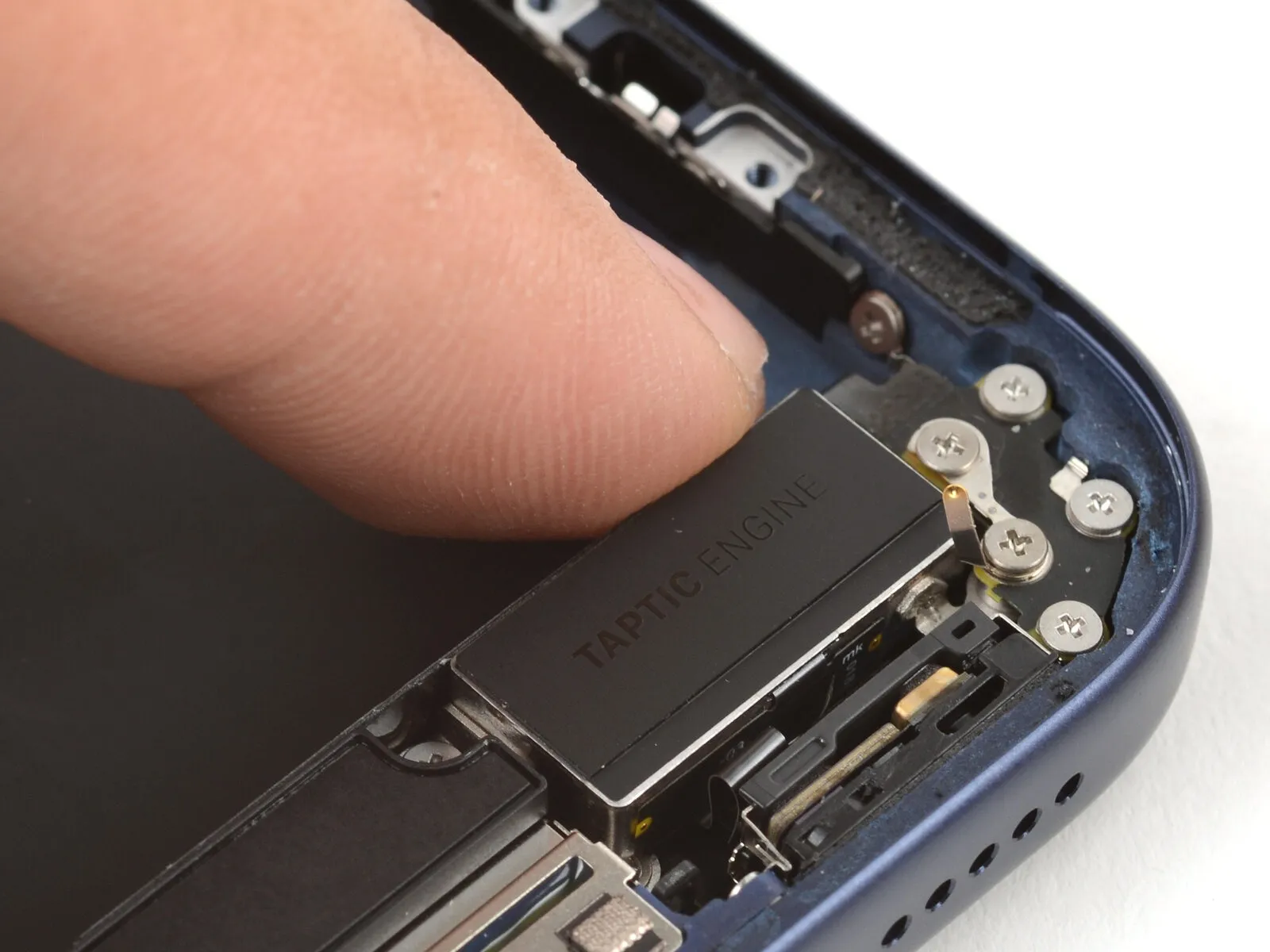
Step 33 | Remove the Taptic Engine
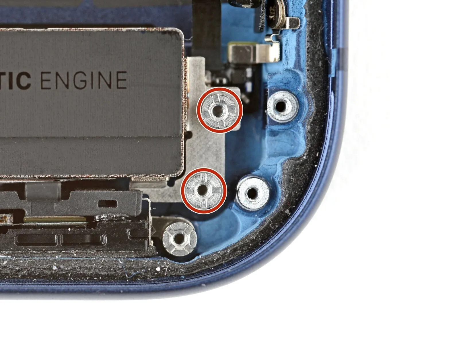
- Employing a standoff screwdriver, detach the Taptic Engine by unscrewing the two 4.0 mm screws that hold it in place.
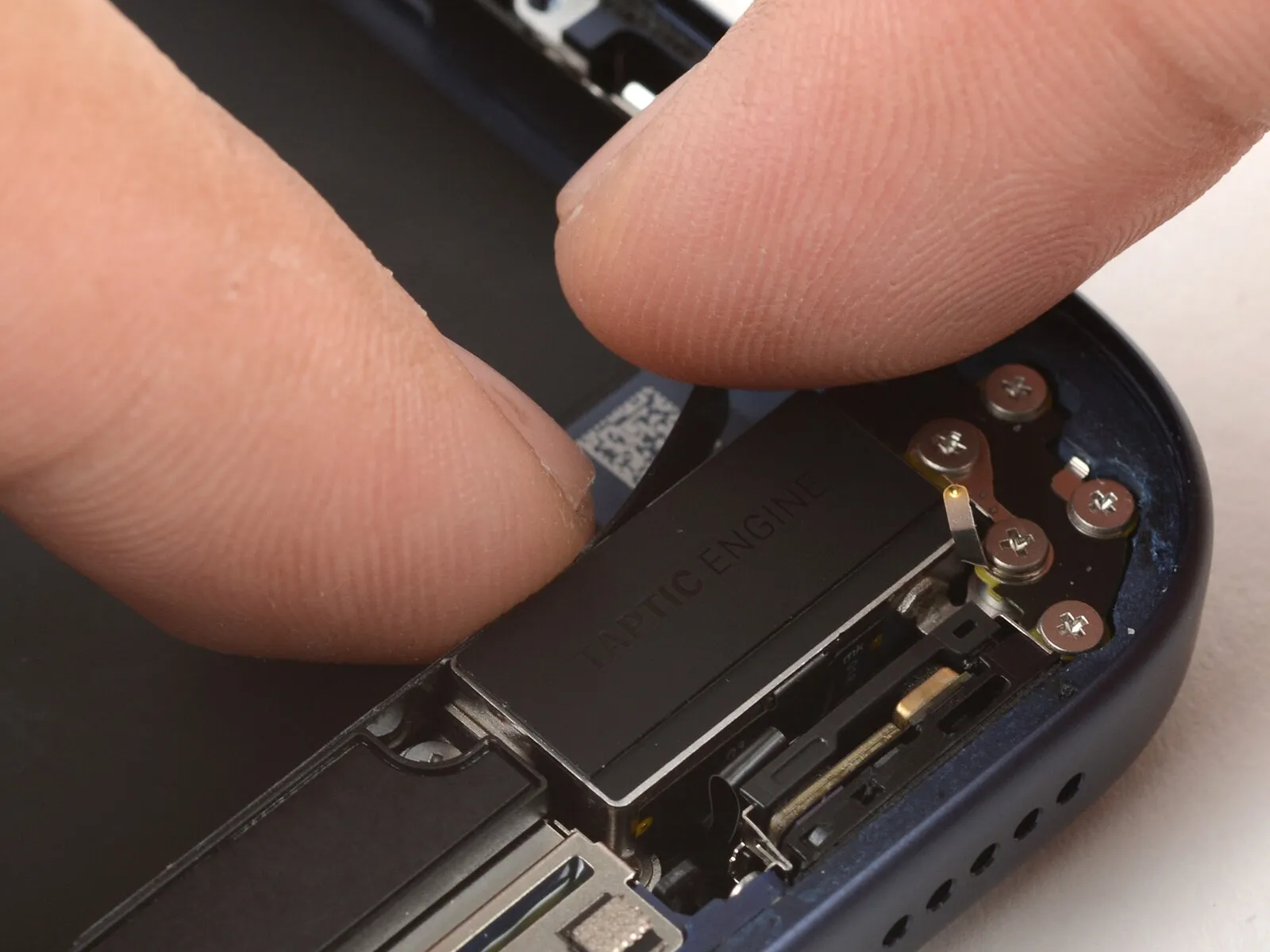
Step 34
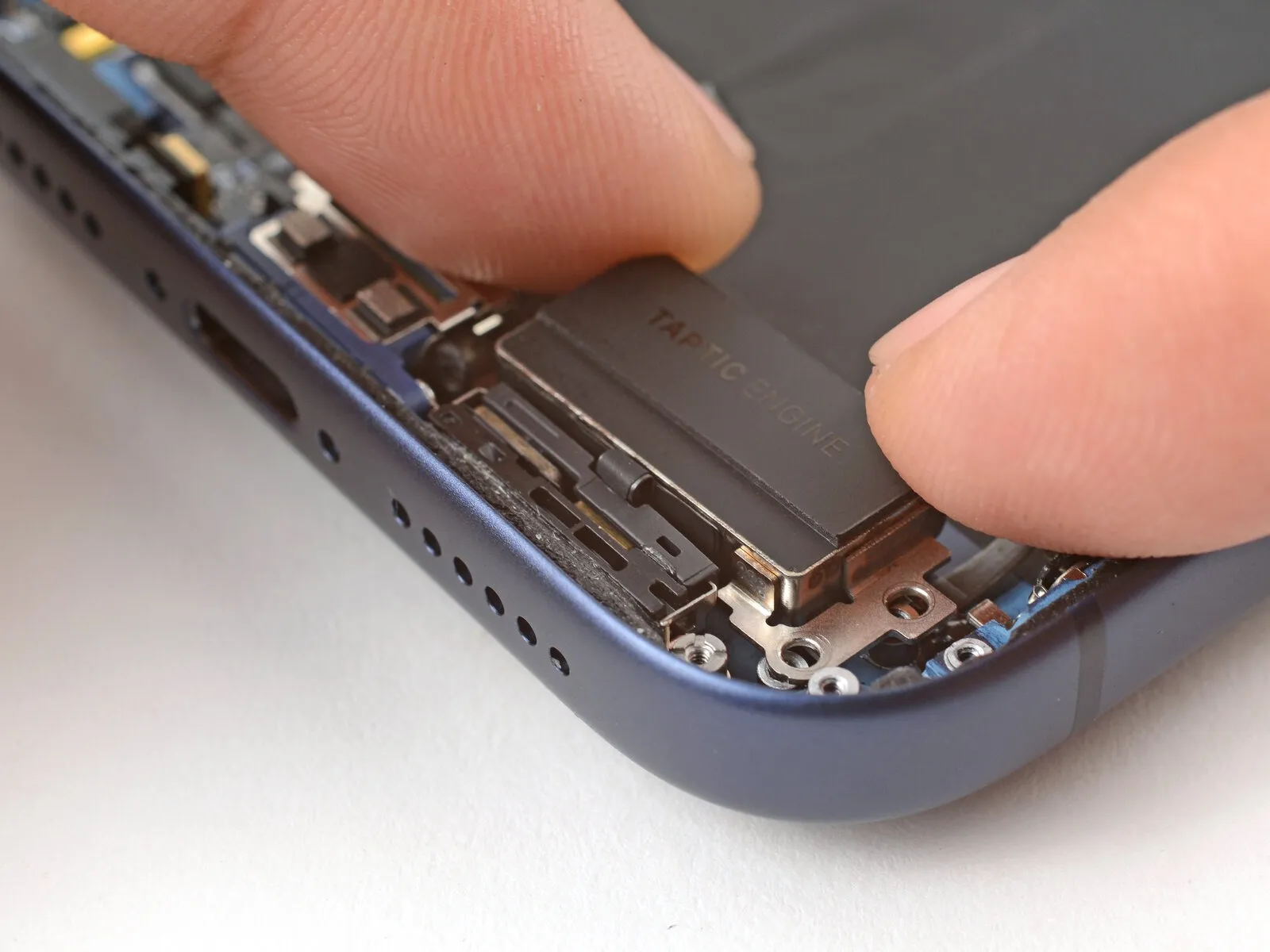
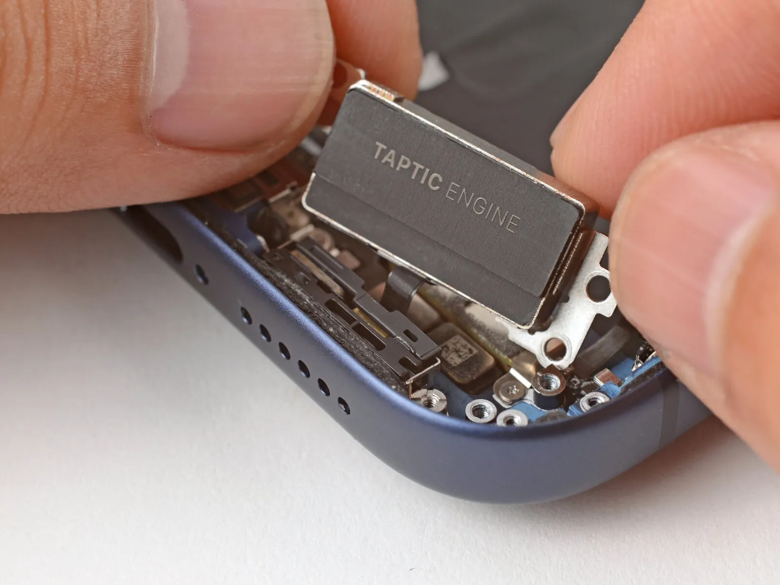
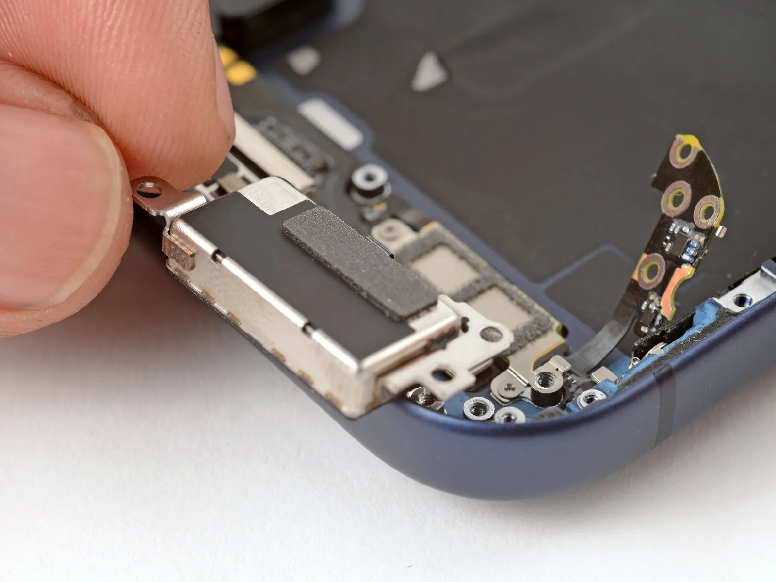
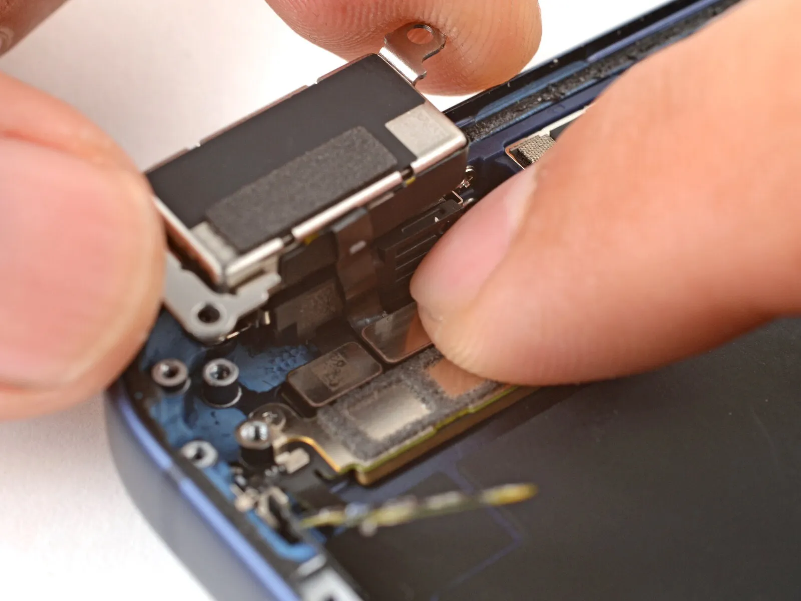
- Using your fingertips, carefully dislodge the Taptic Engine from its housing and position it against the iPhone's edge.
- To avoid cable stress during the subsequent procedure, maintain a firm grip.
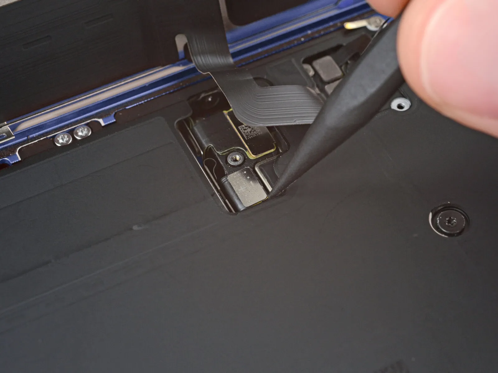
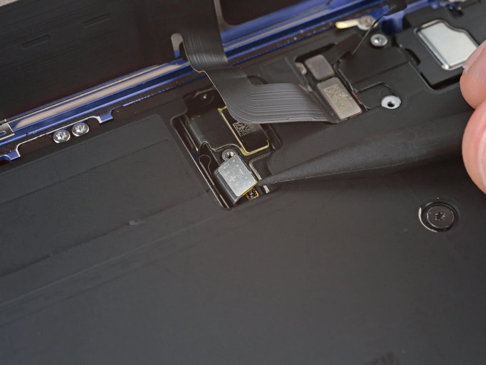
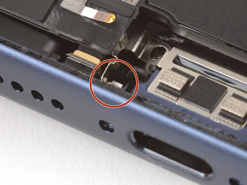
Step 35
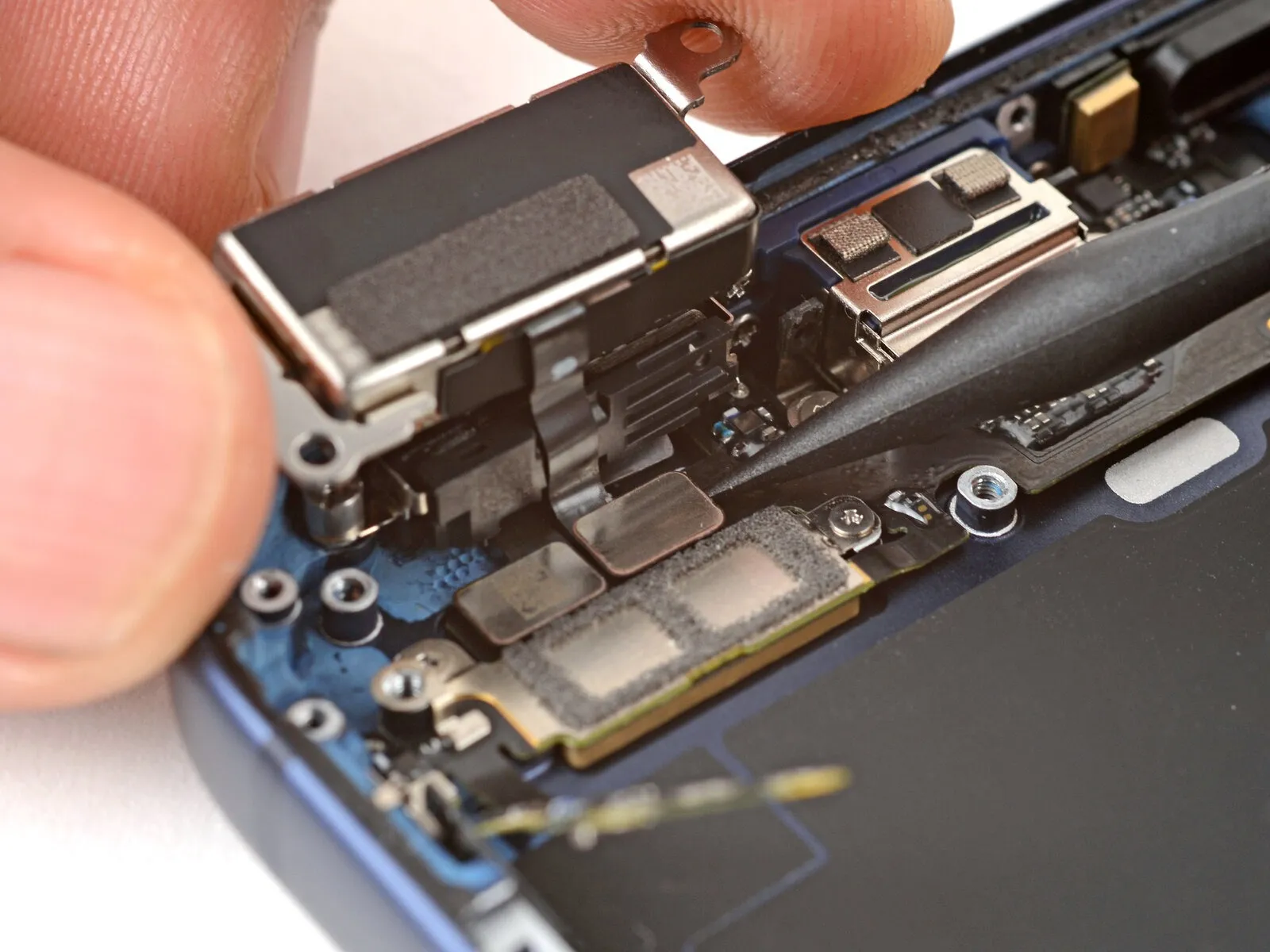
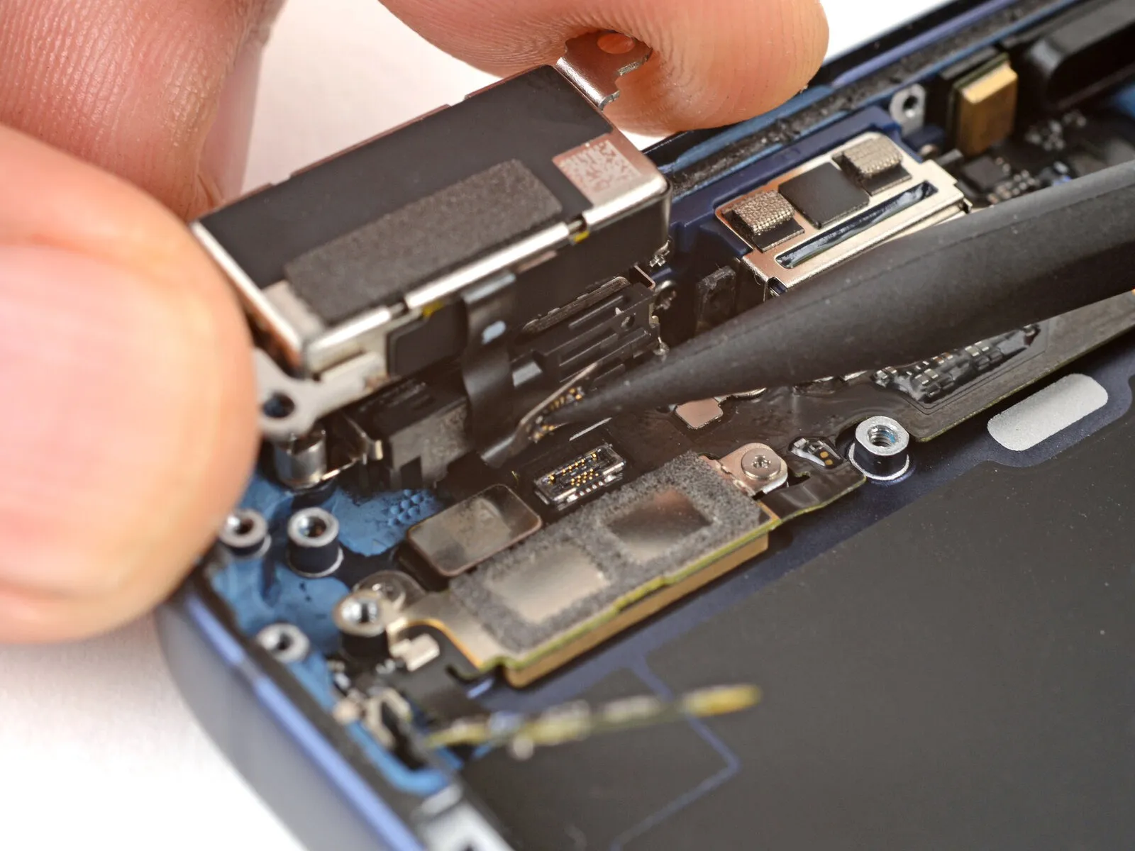
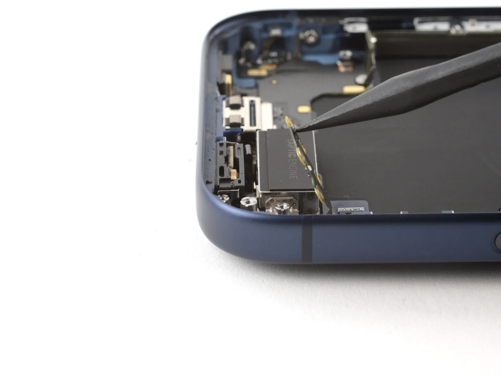
- Carefully leverage a spudger to release the Taptic Engine press connector and subsequently detach it.
Step 36
- Carefully detach the Taptic Engine, ensuring no damage occurs.
Step 37 | Disassembly complete
You’ve successfully disassembled the device; the following instructions detail the reassembly process for your iPhone.
- Visual differences between the repair illustrations and your specific iPhone version are possible.
- This method is applicable to your iPhone model.
Step 38 | Install the Taptic Engine
Position theThe device incorporates a Taptic Engine.Position the component inverted, resting along the perimeter of the iPhone's chassis.
- Securely grasp the Taptic Engine, then engage the press connector with your fingertip to establish a connection.
Step 39

Position the Taptic Engine so its reverse side faces the frame, then ensure proper placement by matching the screw holes.
- Ensure the Taptic Engine flex cable is routed with a clean, even bend connecting the Taptic Engine and the device frame.
Step 40
Secure the two using a standoff screwdriver.Four millimeters.Use the extended Taptic Engine screws, which measure long.
Step 41 | Attach the flex antenna
Gently apply fingertip pressure or a similar tool to.Use a plastic pry tool, often referred to as a spudger.Carefully position the flexible antenna into its folded state.
Step 42
Secure the three components with a JIS 00 screwdriver.The length must measure 2.0 millimeters.Using the 2.5mm hex driver, loosen the screws securing the flexible antenna.
Step 43 | Install the ground clip
Employing tweezers, position the ground clip with precision.
Ensure the clip is positioned as indicated in the accompanying illustrations to guarantee proper alignment.
Step 44 | Install the ground clip
Secure the two components with a JIS 00 screwdriver.Measure the length at precisely 2.0 millimeters.Secure the ground clip by tightening its screws.
Step 45 | Install the loudspeaker

Position the loudspeaker's lower border flush against the frame, then carefully seat it within its designated cavity.
- Verify that the screw tab in the lower-right corner makes full contact with the frame; if misaligned, carefully adjust its position.
- Apply firm, even pressure with your fingertip to the loudspeaker until you hear and feel a distinct click, indicating it is properly seated.
Step 46
- Employ a 3/8-inch socket wrench to tighten the fastener to a torque of 15 ft-lbs, ensuring you observe all safety precautions regarding eye protection and handling sharp edges.Use a JIS 00 screwdriver.Secure the loudspeaker with the provided six screws.
- Use two screws, each measuring 2.7 millimeters in length.
- Use two screws, each measuring 2.0 mm in length.
- A screw, measuring 1.5 millimeters in length, is required.
- A single screw, measuring 1.5 mm in length, secures the iPhone frame to its lower edge.
Step 47 | Install the buffer strip

Carefully reposition the buffer strip against the upper edge of the Taptic Engine, securing it in place with fingertip pressure or a spudger.
Step 48 | Install the battery
- Position the battery tray correctly within its designated area.
Ensure that no wires or cables become pinched or obstructed when the tray is positioned.
Step 49 | Install the battery tray screws
- Employ a 3/8-inch socket wrench to loosen the retaining bolt, ensuring you apply consistent pressure to avoid damaging the threaded connection and observe the torque specification of 12 Nm as indicated in the service manual.Use a screwdriver with a Torx Plus profile and a 4IP size.Secure the battery tray with the provided screws.
- A screw, measuring 7.5 millimeters in length, is required.
- A screw, measuring 5.9 millimeters in length, is required.
- A screw, measuring 3.4 millimeters in length, is required.
- A screw, measuring 2.3 millimeters in length, is required.
- Nine.Screws measuring 3.7 millimeters in length.
- A screw, measuring 3.7 millimeters in length, is required.
Step 50 | Clean the frame


- Carefully maneuver around the delicate grounding clips during frame cleaning; should any become displaced, restore them to their original position using your fingers or tweezers, applying only gentle pressure.
Carefully detach substantial adhesive remnants from the frame's edges, employing either tweezers or your fingertips.
Carefully remove any remaining adhesive with a spudger.
To loosen a firmly bonded adhesive, direct warm air from a hair dryer or heat gun onto the area and reattempt separation.
Step 51

Employing a lint-free cloth or a coffee filter, carefully remove adhesive residue by wiping along the frame's edge in a single direction.
To remove any remaining adhesive film, moisten the cleaning cloth with a small amount of isopropyl alcohol and repeat the wiping process.
Careful execution is essential; a thoroughly cleaned frame surface enables the new adhesive to spread uniformly, which is critical for a strong, reliable bond.
Step 52 | Clean the screen

To facilitate proper adhesion when reinstalling a display, use a microfiber or lint-free cloth lightly dampened with a small amount of isopropyl alcohol having a concentration exceeding 90% and clean the display's edges.
Step 53 | Orient the replacement adhesive


To confirm correct placement, position the adhesive sheet on top of the frame, ensuring the protective liners remain intact.
Carefully observe the frame's top and bottom edges, noting the camera opening and any notches, to help guide proper adhesive placement.
Step 54 | Apply the replacement adhesive

Carefully lift the corner tab of the adhesive backing and remove the liner, revealing approximately one-third of the adhesive surface.
Because the adhesive is highly adhesive, avoid contact with other surfaces until you intend to bond it to the frame.
Remove the protective layers from the adhesive until the surface designed to bond with the frame is revealed.
Step 55


Because the adhesive bonds immediately upon contact, any repositioning attempts will fail, requiring removal of the existing adhesive and replacement with a fresh application.
Ensure the adhesive strip's visible border is precisely matched to the iPhone frame's matching edge.
Ensure proper positioning, then apply even pressure to secure the adhesive strip to the frame.
Step 56


- Carefully remove the adhesive backing by gently separating the protective liner.
- Apply even pressure to ensure the adhesive makes full contact with the surface.
- Proper adhesive placement ensures the edges seat flush and align precisely.
- Carefully reposition any slight adhesive misalignment by gently drawing the extended edges toward the frame.
- Should the adhesive display creases or wrinkles, discard the affected material and reapply with a new portion.
- Should a replacement set of adhesive strips be unavailable, the iPhone can be reassembled and operated without them; however, be aware that the device's water resistance will be reduced until the adhesive is properly replaced.
Step 57

- Employ a spudger for this step.Ensure the adhesive strip is firmly applied by applying even pressure across its full circumference.
- Carefully avoid damaging the delicate grounding clips; if one becomes dislodged, reposition it with a light touch.Carefully restore the component to its original shape using your fingers or tweezers..
- Apply gentle pressure to avoid distorting or overextending the adhesive.
Step 58


- Grasp the protruding tab to release.Carefully remove the sizable front adhesive liner, locating and utilizing the pull tab, typically situated at a corner, to facilitate separation.
- The protective liners remain in place around the device's edges; leave them undisturbed during reassembly to avoid unintended adhesive bonding.
Step 59 | Connect the screen

Position the iPhone display adjacent to the frame, ensuring sufficient cable slack for connection to the logic board.
Step 60


- Apply pressure with a fingertip or the broad, planar end of a spudger.Carefully align and secure both screen connectors to the logic board, ensuring a firm connection.
- Ensure the connector is properly aligned before applying pressure; if resistance is encountered, adjust its position and attempt connection once more.
Step 61 | Connect the battery


Carefully depress the component with a fingertip or the broad, planar end of a specialized tool.Use a plastic pry tool, often referred to as a spudger.Align the battery connector and firmly secure it to the logic board.
Step 62 | Test your repair

- Before reassembling the iPhone, verify the repair's functionality by powering on the device and confirming it operates normally.
- Following power-down, proceed with the remaining assembly steps.
- To troubleshoot a non-responsive iPhone, establish a connection to a power outlet and attempt to power it on.
Step 63 | Install the battery connector cover


Ensure the battery connector cover's upper edge is fully seated beneath the designated lip, verifying that both tabs are secured within the recess. Position the cover so the screw hole is aligned, then gently place it into its intended location.
Step 64

Employ a 3/8-inch socket wrench to tighten the fastener to a torque of 15 Nm, ensuring proper engagement and preventing damage.Use a JIS 00 screwdriver.Secure the component using the specified fasteners, ensuring proper alignment with the designated mounting points and adhering to the torque specification of 5 Nm.A screw measuring 1.2 millimeters in length.Fasten the battery connector cover using the provided screw, ensuring it is tightened to a torque of 5.0 Nm with a 4mm hex key, and observe the warning regarding potential damage from over-tightening.
Step 65 | Install the screen connector cover


Position the left side of the screen connector cover beneath the designated notch, ensuring the screw opening is properly aligned before setting it down.
Step 66

Employ a JIS 00 screwdriver to fasten the screen connector cover with the 1.2 mm screw.
Step 67 | Remove the final adhesive liners


- Using a firm grip, stabilize the display panel with your hand.
Carefully remove the surrounding liners, revealing the adhesive layer; this can be accomplished by hand or with a spudger.
Avoid contact with the adhesive surface.
Ensure all liners are absent; carefully inspect and discard any that are present.
Step 68 | Install the screen


- Position the screen against the frame, initiating the placement with the uppermost border.
Should you encounter difficulty during assembly, a perimeter clip might be deformed and obstructed by the frame; carefully examine the area where the resistance is felt and carefully restore any clips to their original shape.
Carefully guide the display into position, ensuring no wires are compressed while applying even pressure around the perimeter to achieve a seamless fit with the iPhone's chassis.
Step 69


- Apply consistent, even pressure encompassing the device's full outer edge.
Step 70 | Apply heat to the perimeter

- Apply warmth around the screen's edges with a hair dryer or heat gun, ensuring the surface reaches a temperature just beyond comfortable touch.
Applying the solvent loosens the existing glue, which promotes a stronger new adhesion.
Step 71 | Install the pentalobe screws
- Employ a 3/8-inch socket wrench to securely tighten the fastener to a torque of 15 Nm, ensuring proper engagement and preventing damage to the component.Use a P2 screwdriver with a pentalobe tip.Secure the pair using the specified fasteners.Screws measuring 7.5 millimeters in length.Locate the two components flanking the charging port.