iPhone 17 Pro Max LiDAR Module Replacement
Using these instructions, you can detach and substitute the Employ the laser-based remote sensing technology. Locate the module within the iPhone 17 Pro Max.
A malfunctioning measurement application suggests a possible need to substitute the sensor assembly. Employ the laser-based remote sensing technology to gather data. The component designated "module"
Employ the laser-based remote sensing technology, commonly referred to as Lidar, to gather data. Accessing the module necessitates a complete teardown of the device, as it's situated beneath the main circuit board.
Step 1 | Safety precautions


To ensure optimal conditions for this repair procedure, allow the iPhone battery to discharge to a level below 25% prior to commencing work.A compromised lithium-ion battery presents a fire hazard when energized.
- Disconnect all wires and connectors from the device.
- Simultaneously press the power button and one of the volume buttons, then slide your finger across the screen to initiate the power-off sequence.
Step 2 | Cracked glass preparation


To prevent potential injury or equipment damage, exercise care.Because broken glass presents a risk of cuts or can hinder the repair process, proceed to the following step if your phone's screen is damaged.
- To prevent glass fragments from scattering and to ensure proper adhesion of the suction cup, thoroughly cover the damaged area with packing tape.
- Apply a non-overlapping strip along the lower edge, ensuring it's sized to accommodate a suction cup.
- Apply the protective tape solely to the glass surface, ensuring no adhesive contacts the frame.
Step 3 | Remove the pentalobe screws


Employ a 3/8-inch socket wrench to loosen the retaining bolt, ensuring you maintain a firm grip and avoid over-tightening during reassembly, as excessive force can damage the threaded portion of the shaft.Use a P2 screwdriver with a pentalobe tip.Using the appropriate screwdriver, detach the two screws, each measuring 7.5 mm in length, located on both sides of the charging port.
Step 4 | Mark your opening picks


To prevent potential injury or damage, exercise care when proceeding, as the component involves a 12-volt electrical connection and requires the use of a 5mm hex key.Excessive insertion of the opening pick may result in device damage.
- Using a permanent marker, indicate the location of a 3 mm measurement originating from the tip on the opening pick.
- To achieve a similar effect, affix a coin to the pick's tip, positioning it precisely 3 millimeters away.
Step 5 | Heat the bottom edge

To prevent potential injury or equipment damage, exercise care.Careless application of heat from the heat gun may damage the display and/or battery; consult the provided instructions for proper technique.
- Apply warmth to the lower edge of the screen with a hair dryer or heat gun, ensuring the surface reaches a temperature just beyond comfortable touch.
Step 6 | Apply a suction handle


Using a suction tool, carefully draw the screen's lower border upward, positioning the tool as near the edge as feasible.
Step 7 | Screen bezel information


Carefully position your pick to ensure it's placed precisely where it needs to be for the subsequent procedure.
- Position your pick beneath the plastic bezel, which is located on the screen's lower edge where it meets the frame, ensuring the pick is fully separated from the bezel.
- Avoid inserting a pick into the joint where the plastic bezel meets the display panel, as doing so will cause them to detach, making the repair process more difficult.
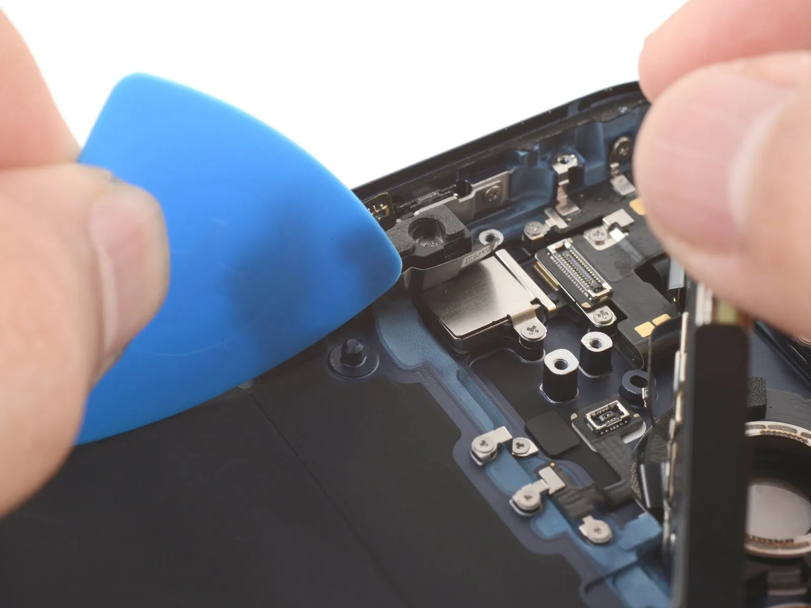
Step 8 | Insert an opening pick


Apply firm, consistent upward pressure to the suction handle to create separation between the display screen and its surrounding frame.
Applying considerable pressure might be necessary; if you encounter resistance, reapply heat to the display and attempt separation once more.
Using a prying tool, carefully slide its tip into the space you've made.
Step 9 | Screen information
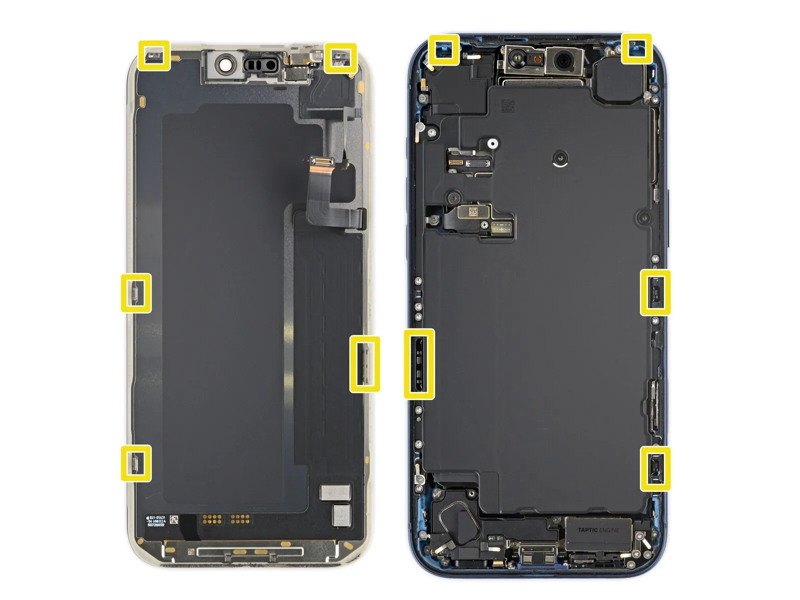
Limit pick insertion depth to avoid damage.Three millimeters.To prevent harm to the subsequent components, exercise caution when working beneath the display surface.
- Close to the volume and Action buttons, you'll find the cables connecting the screen and ambient light sensor.
- The phone's internal components feature sensitive, circular contact points utilizing springs.
- Metal clips, located on the screen's lower surface, secure it to the frame via matching slots.
Step 10 | Separate the bottom edge adhesive


Using the opening pick, carefully work along the lower perimeter to release the adhesive bond.
To stop the adhesive from bonding again, maintain a small tool in the lower right corner.
Step 11 | Remove the suction handle

To detach the suction cup, grip the small projection extending from its surface and draw it away from the screen.
Step 12 | Heat the right edge


Apply warmth to the right screen perimeter with a hair dryer or heat gun, ensuring the surface reaches a temperature just beyond comfortable touch.
Step 13 | Separate the right edge adhesive


- Using a specialized opening pick, carefully slide it between the display assembly and the device casing, positioning the pick's tip just beneath the lower-right corner.
- Using a pick, gently lift the right side to break the adhesive bond and disengage the two retaining clips; a slight upward movement of the screen may be necessary to fully release the clips.
- To stop the adhesive from bonding again, maintain a small tool positioned in the upper right corner.
Step 14 | Heat the top edge


Apply warmth to the screen's upper border with a hair dryer or heat gun, ensuring the surface reaches a temperature just beyond comfortable touch.
Step 15 | Separate the top edge adhesive


- Using a specialized opening pick, carefully slide it between the screen and the device's housing, positioning the pick's tip just beneath the screen's upper-right corner.
- Carefully insert a pick along the upper edge, extending it just slightly around the top left corner to break the adhesive bond and disengage the two clips; avoid excessive insertion beyond this point to prevent potential damage to the ambient light sensor cable.
- To stop the adhesive from bonding again, maintain a small tool in the upper left corner.
Step 16 | Heat the left edge


Apply warmth to the left screen perimeter with a hair dryer or heat gun, ensuring the surface reaches a temperature just beyond comfortable touch.
Step 17 | Separate the left edge adhesive


- Using a fourth opening pick, carefully slide it between the screen and the device's frame, positioning it directly beneath the bottom left corner.
- Carefully insert a pick along the left side, gently working it between the adhesive layers to detach them and free the clip, but halt the separation process immediately prior to reaching the volume up button.
- To detach the clip, gently lift the screen a small amount; avoid inserting the pick deeper, as this could harm the screen cable.
Step 18 | Prop up the screen
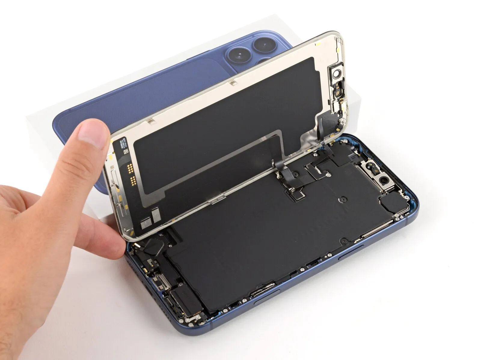
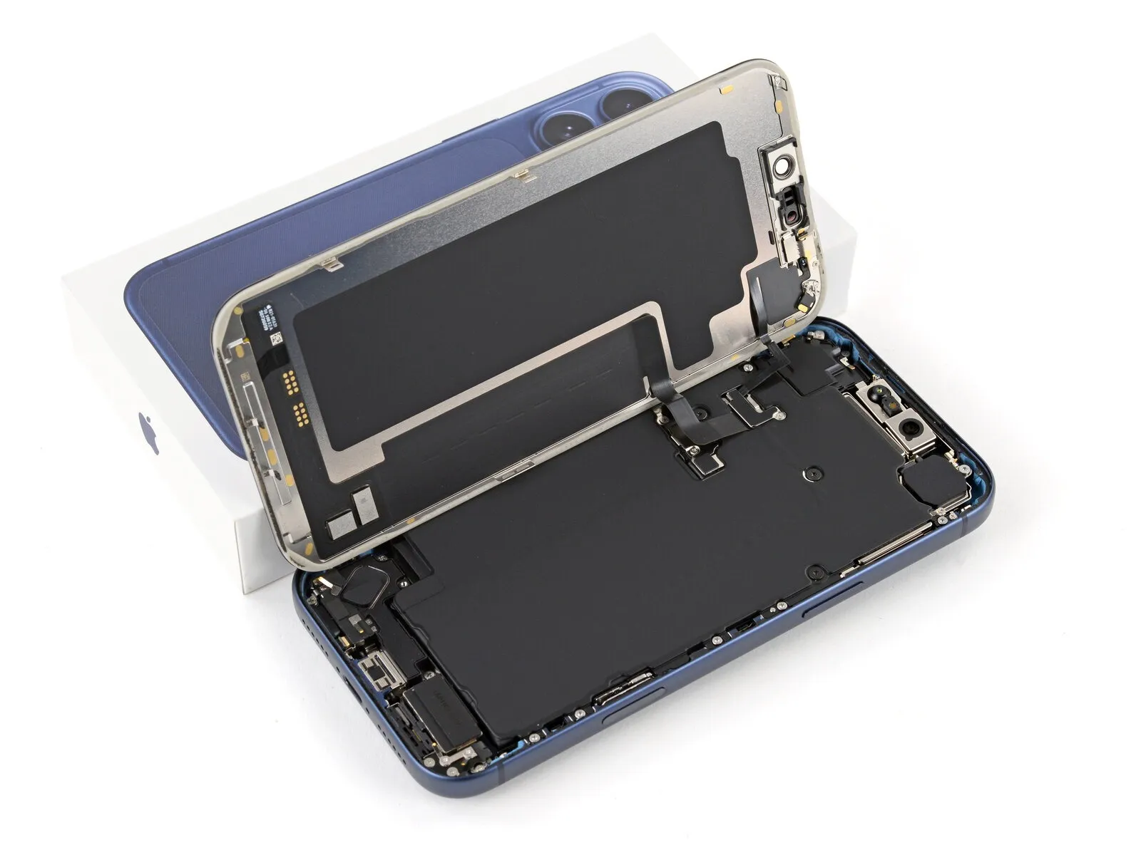
Ensure the display is fully released from the chassis; if resistance is encountered, re-examine the edges to disengage any lingering adhesive or fasteners.
To free the display, raise it vertically and pivot it toward the left side, supporting it with a stable object like a container or pile of books to prevent cable stress. As an alternative, carefully position the display horizontally on its left edge.
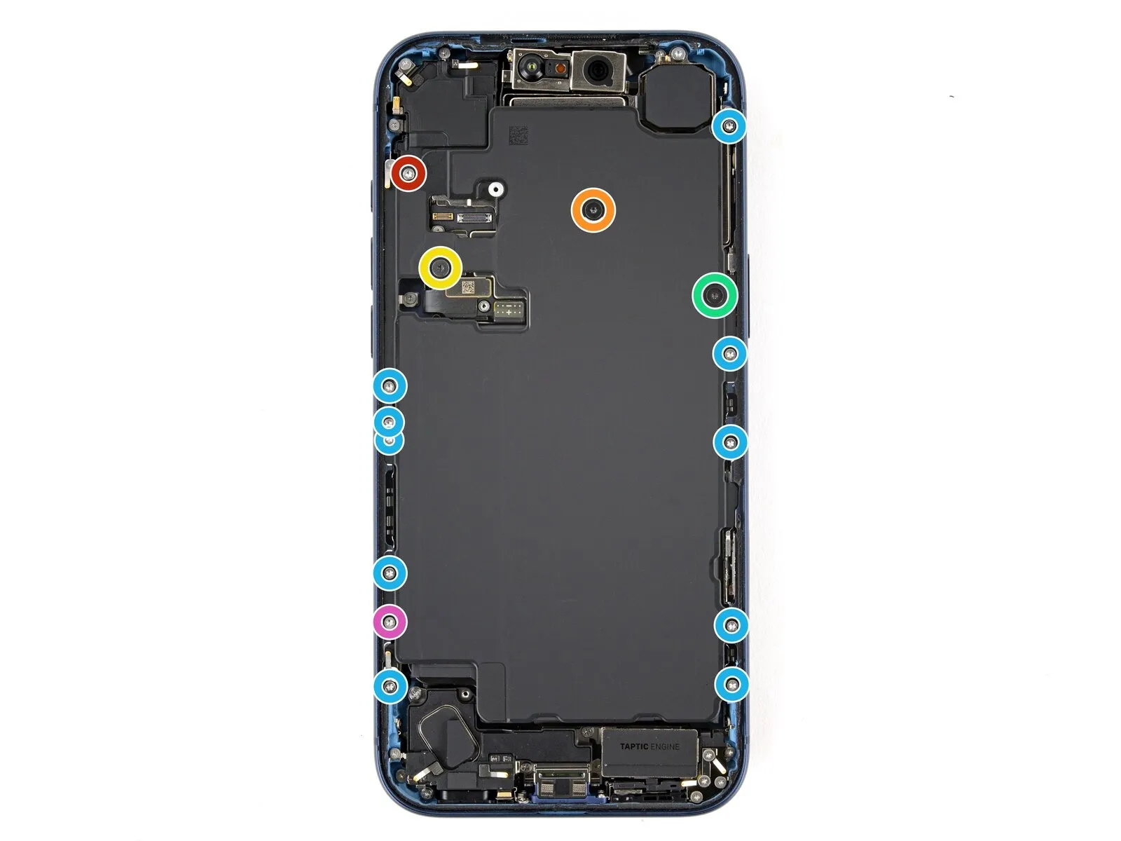
Step 19 | Remove the cover screws
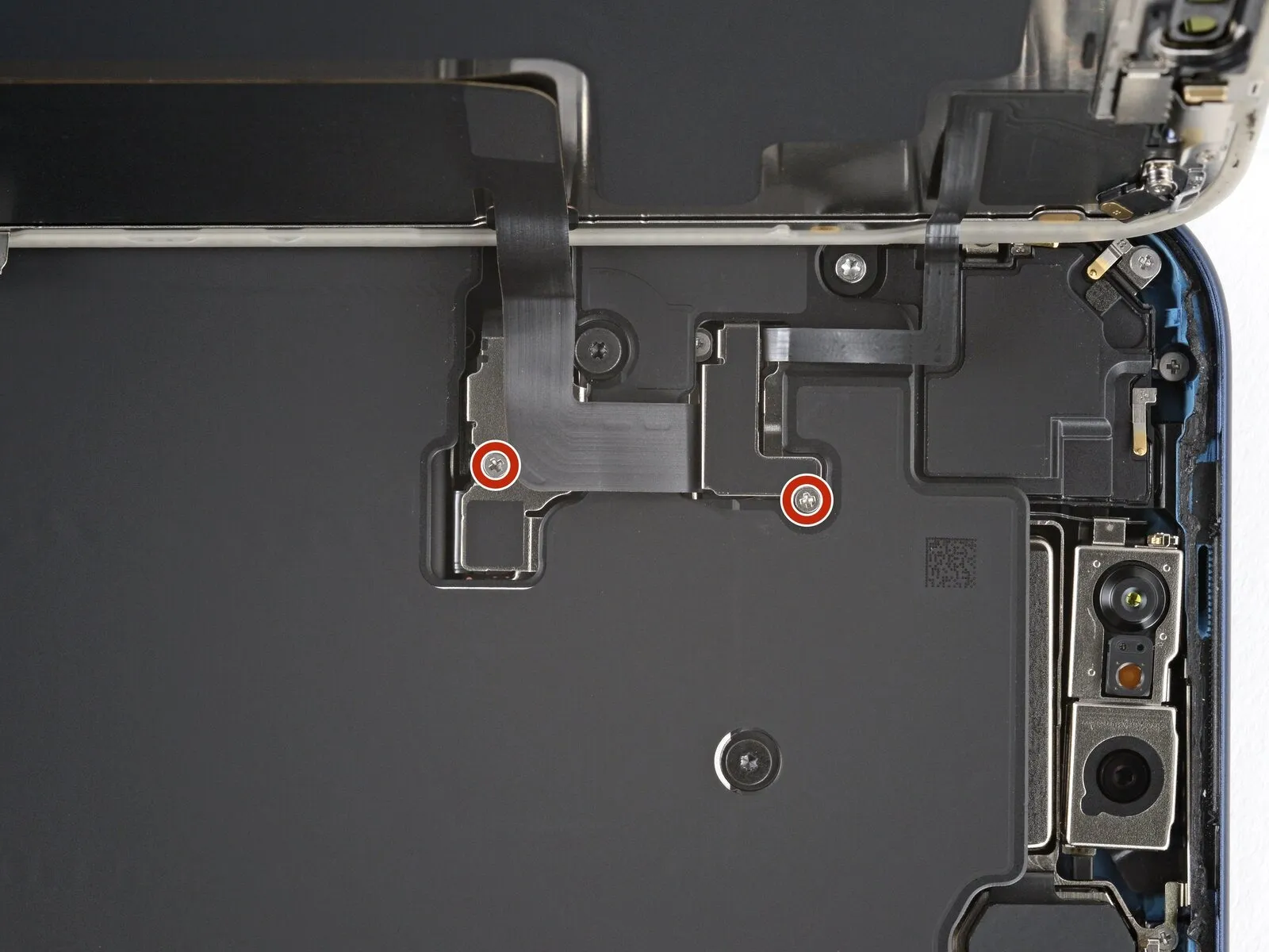
Carefully organize all screws during disassembly, noting their original locations to ensure correct reassembly.
Employ a Japan Industrial Standard screwdriver.00Use a screwdriver to detach the pair.One point two millimeters.Use one long Phillips screw to fasten each battery and screen cable cover in place; these screws are specifically compatible with small iFixit Phillips bits, though other Phillips screwdrivers may be attempted with caution to avoid damaging the screw heads.
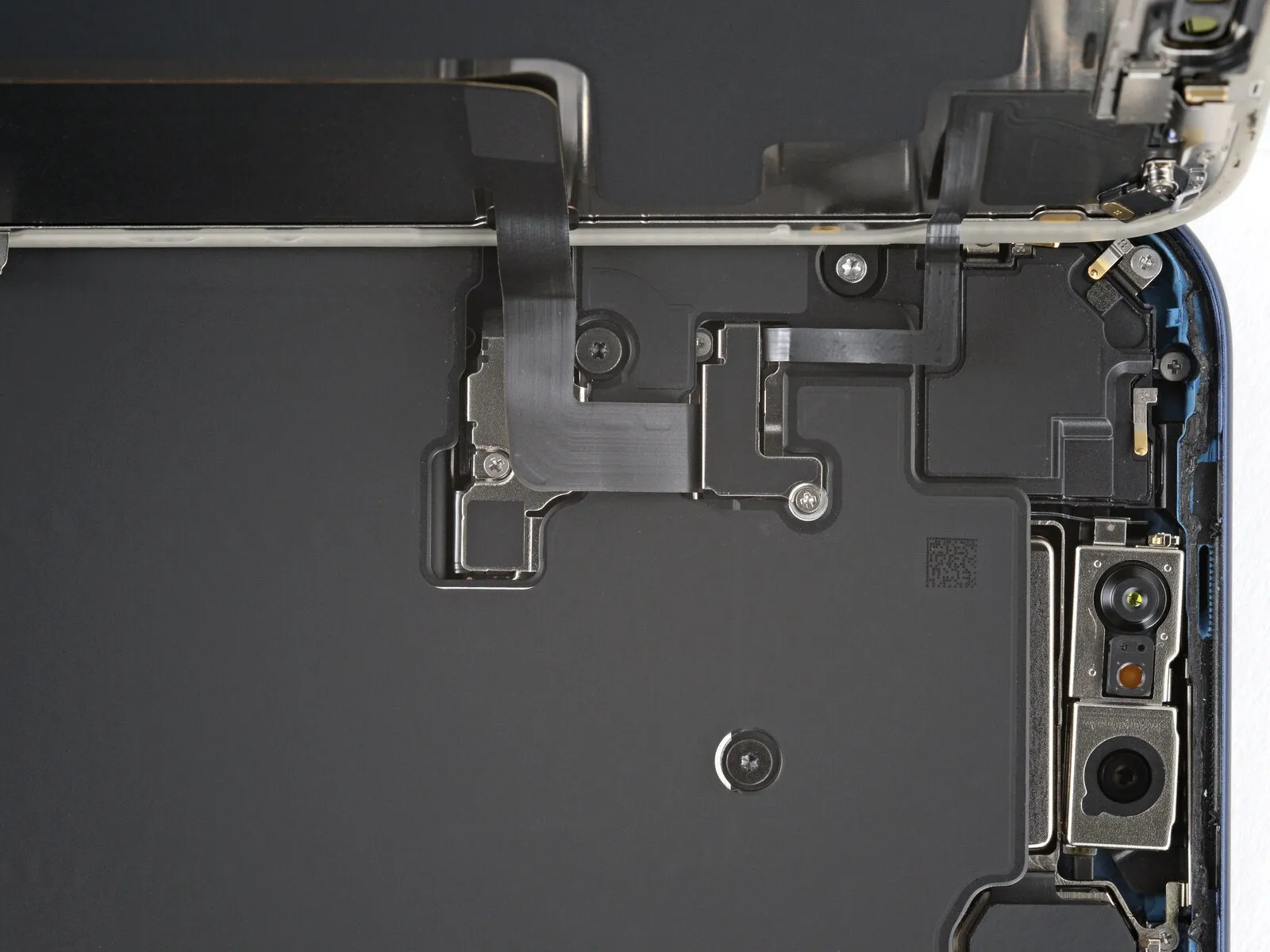
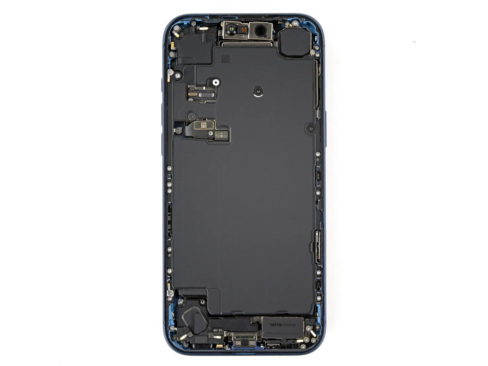
Step 20 | Remove the covers


Detach the two protective covers.
Step 21 | Disconnect the battery

- Carefully employ the tip of a screwdriver to apply pressure.Use a plastic pry tool, often referred to as a spudger, to gently separate components.Use a prying tool to release and separate the battery press connector.
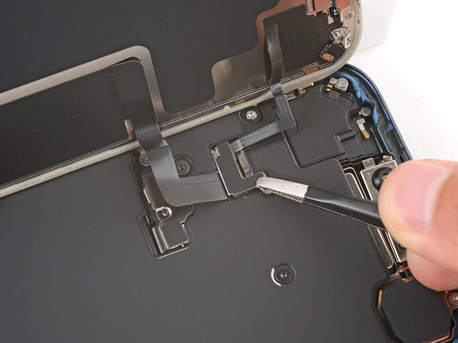
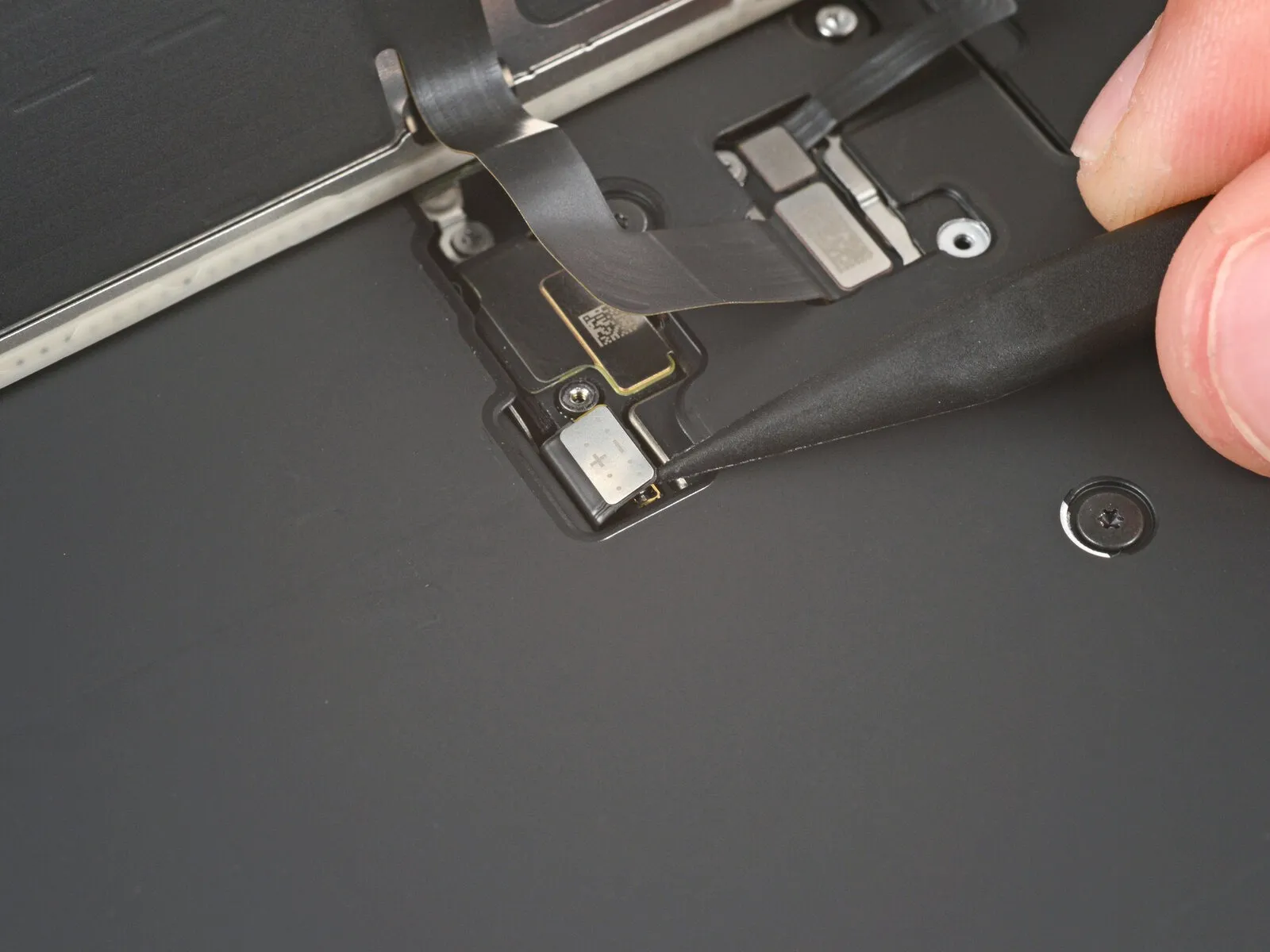
Step 22 | Disconnect the screen


- Carefully insert the pointed end of a prying tool.Use a plastic pry tool, often referred to as a spudger.Release the screen and front sensors from their connections by carefully disengaging the connectors.
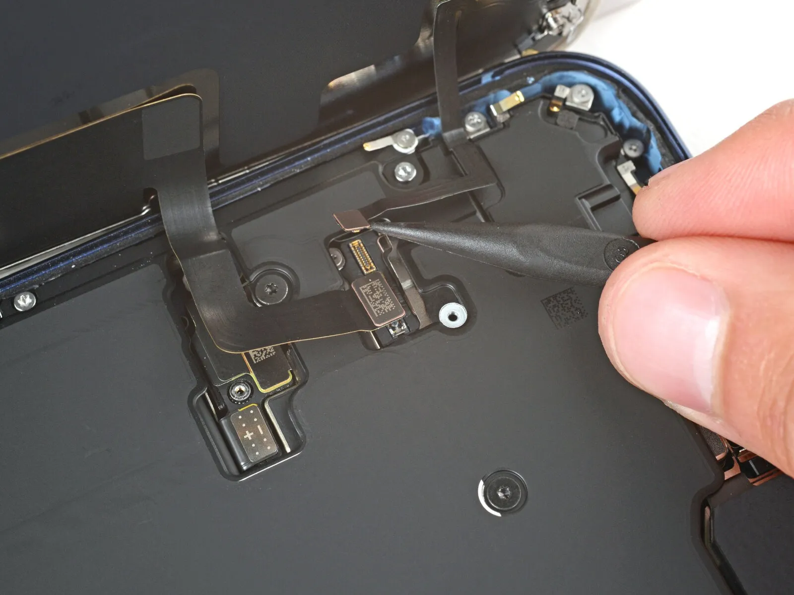
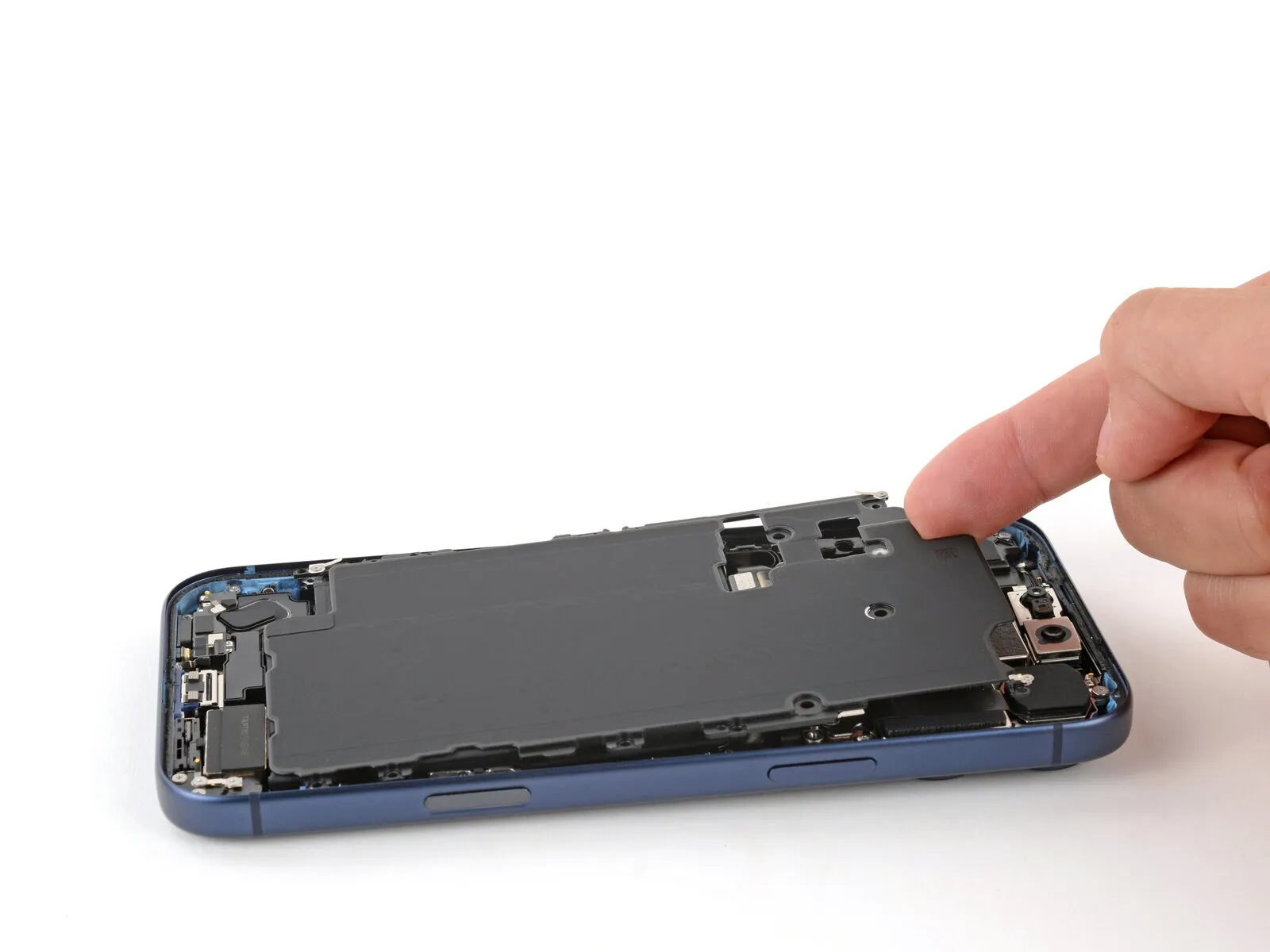
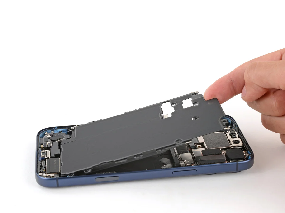
Step 23 | Remove the screen
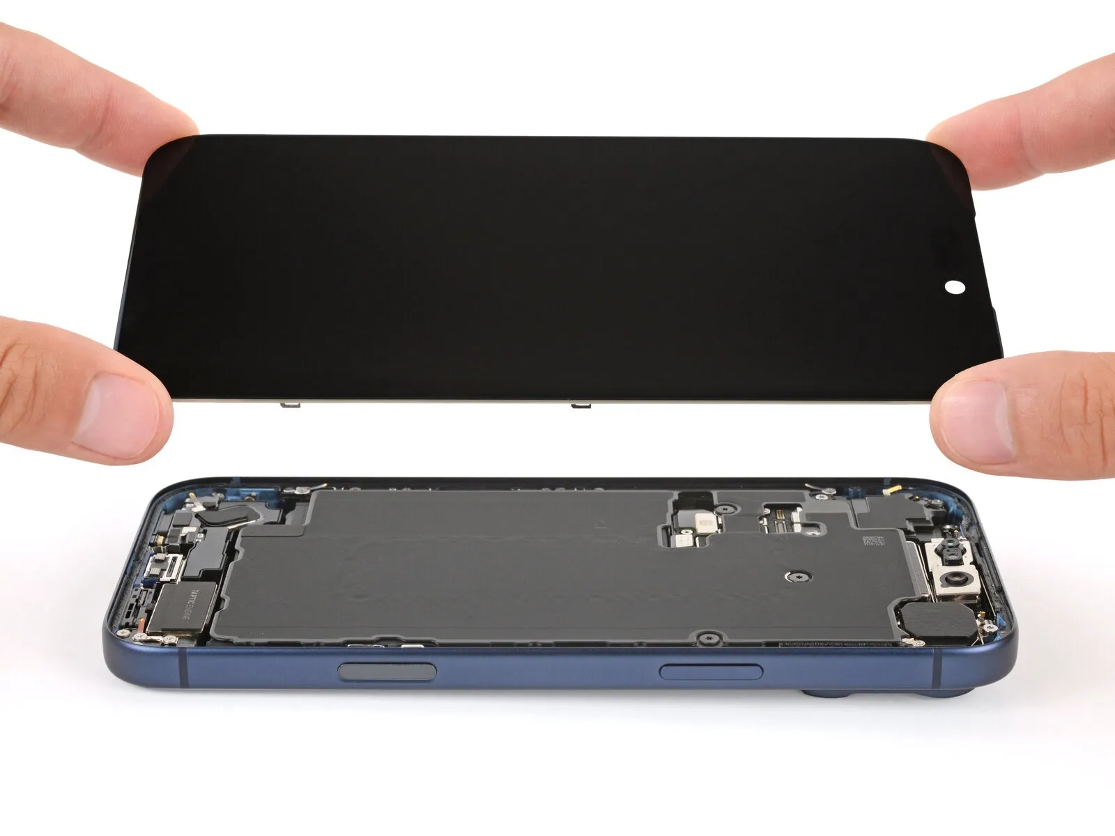
- Carefully detach theCarefully detach the display panel, ensuring you use the specialized prying tool to avoid scratching the surface or damaging the surrounding components, and note that the screen assembly measures 6.5 inches diagonally and requires a Phillips #0 screwdriver to release the securing screws..
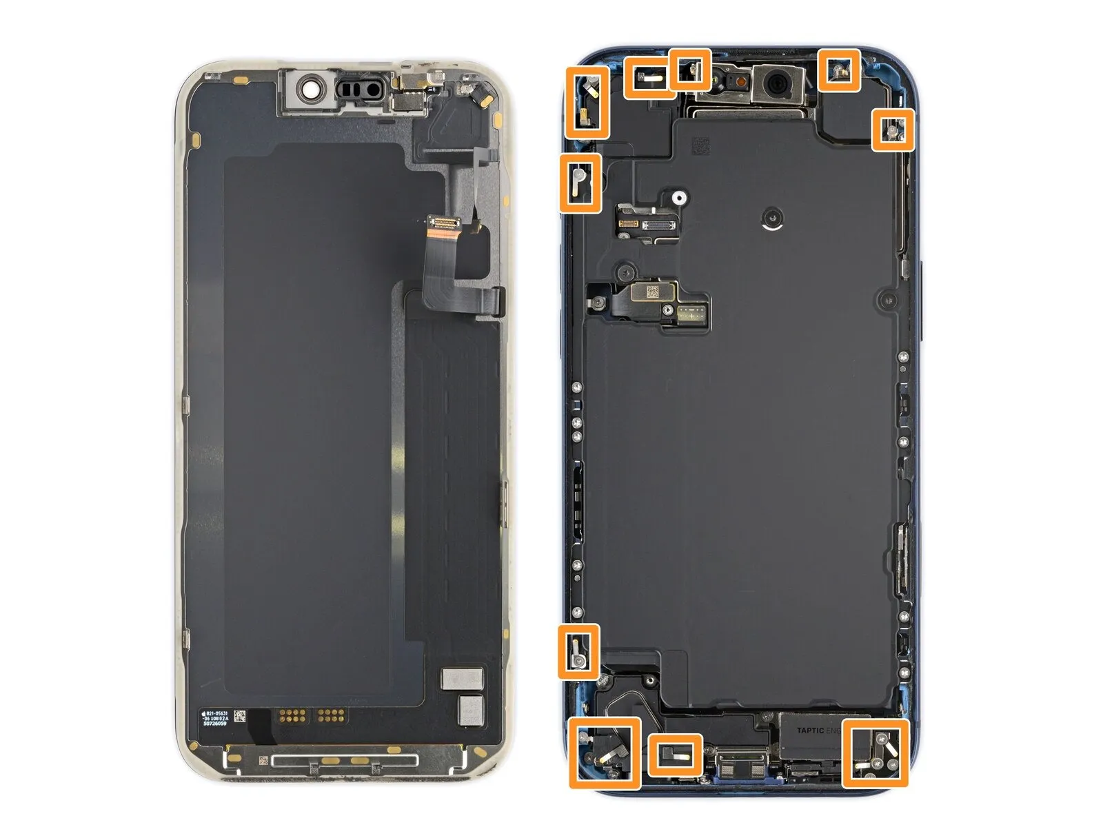
Step 24 | Remove the battery screws
- Employ a 3/8-inch socket wrench to tighten the fastener to a torque of 15 Nm, ensuring the correct specification is met and preventing damage to the component.Utilize a screwdriver with a Torx Plus profile, size 4IP.Use a T15 Torx screwdriver to detach the battery tray by unscrewing the fasteners.
Begin the process by executing step one.A screw measuring 7.5 millimeters in length.
Begin the process by executing action number one.A screw with a length of 5.9 millimeters.
Begin the process by executing the action designated as "One."A screw measuring 3.5 millimeters in length.
Begin the process by executing action number one.A screw measuring 2.4 millimeters in length.
Ten.Screws with a length of 3.7 millimeters.
Begin the process by executing the action designated as "One."A screw measuring 3.7 millimeters in length.
This screw is absent from iPhone versions that utilize a physical SIM card.
Step 25 | Remove the battery

- Employ the specified tool to proceed.Use a digit to apply pressure.Carefully raise the battery tray's upper left corner to disengage it.
Avoid contact with the front-facing camera lens to prevent any blurring or obstruction of the image.
Step 26 | Remove the rear camera connector cover
Employ a Y000 tri-point screwdriver for the removal process.One millimeter.A lengthy screw fastens the cover protecting the rear camera connector.
Step 27

Carefully detach the rear camera connector cover from the logic board using tweezers.
Step 28 | Disconnect the rear camera assembly
Carefully use a spudger to lift and detach the three camera connector assemblies located at the rear; note that one connector is positioned beneath another.
Step 29 | Remove the rear camera assembly
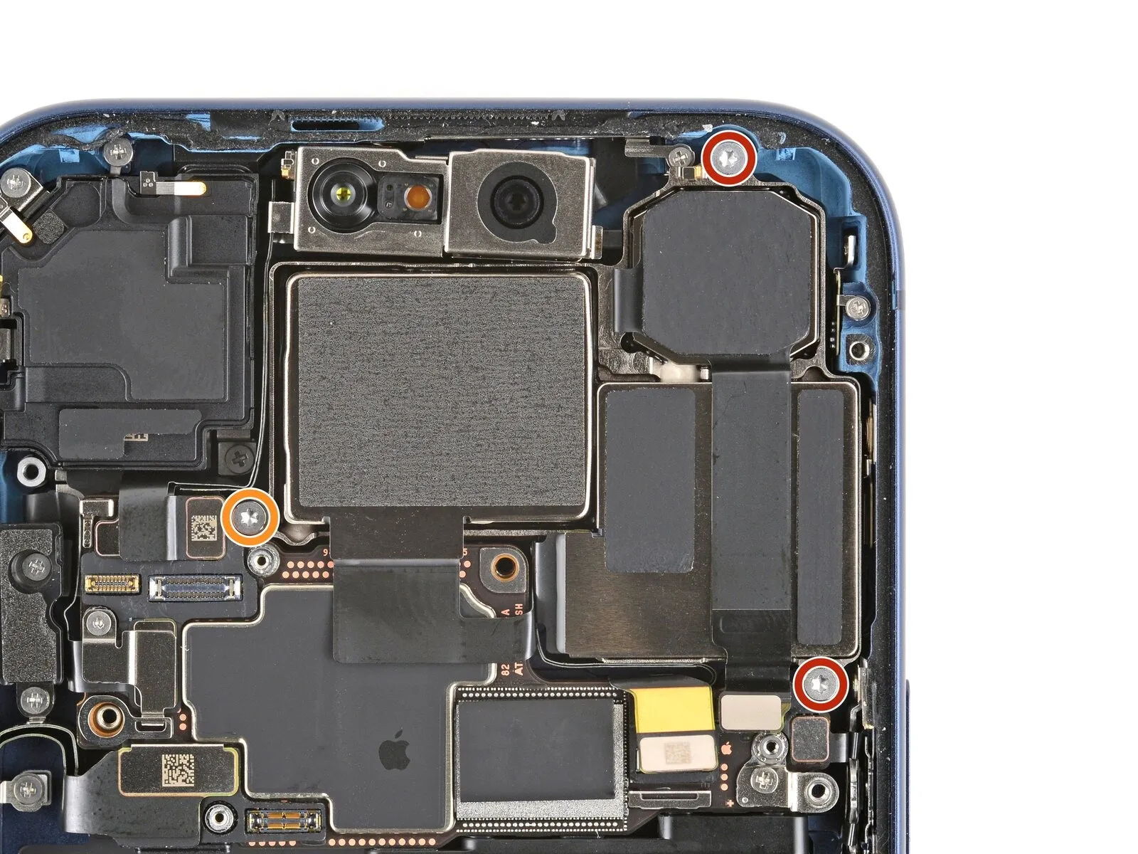
Employ a 3/8-inch socket wrench to loosen the fastener, ensuring you apply consistent pressure to avoid damaging the threads, and then carefully remove it.Utilize a screwdriver with a Torx Plus profile, size 4IP.Use a Phillips screwdriver to detach the three screws that hold the rear camera assembly in place.
- Two.Screws measuring 4.0 millimeters in length.
- Begin the process by executing the action designated as "One."A screw measuring 4.4 millimeters in length.
Step 30

Carefully employ the tip of a screwdriver to apply pressure.Use a plastic pry tool, often referred to as a spudger.Using your fingers, carefully lift the rear camera assembly's upper edge, then detach it.
Step 31 | Remove the front camera connector cover

Employ a 3/8-inch socket wrench to loosen the fastener, ensuring you apply steady pressure to avoid damaging the threads, and then carefully remove the component.Use a Y000-sized screwdriver with a three-pronged tip.Detach the component.A screw measuring 1.0 millimeters in length.Ensure the front camera connector cover is firmly in place.
Step 32

Carefully detach and remove the front camera connector cover using tweezers.
Step 33 | Remove the front camera assembly
Carefully insert the tip of a screwdriver to.Use a spudger.Carefully use a prying tool to separate and release the two front camera connectors from the logic board, noting that one connector is positioned beneath the other.
Step 34
Carefully detach the front camera assembly from its housing.
Step 35 | Remove the top speaker
Employ a JIS 00 screwdriver to detach the three screws that hold the top speaker in place.
Step 36


Carefully insert the tip of a 3mm Allen wrench.Use a plastic pry tool to access.Carefully use a prying tool to gently separate the top speaker from its housing.
Carefully detach the speaker assembly labeled "top speaker."
Step 37 | Remove the button connector cover
Employ a 3/8-inch socket wrench to loosen the retaining bolt, ensuring you maintain a firm grip and wear safety glasses to protect against potential debris.Use a Y000-sized screwdriver with a three-pronged tip.Detach the component.A screw measuring 1.0 millimeters in length.Ensure the button connector cover is firmly in place.
Step 38
Carefully detach the button connector cover from the logic board by releasing its latch with tweezers, then lift the cover away.
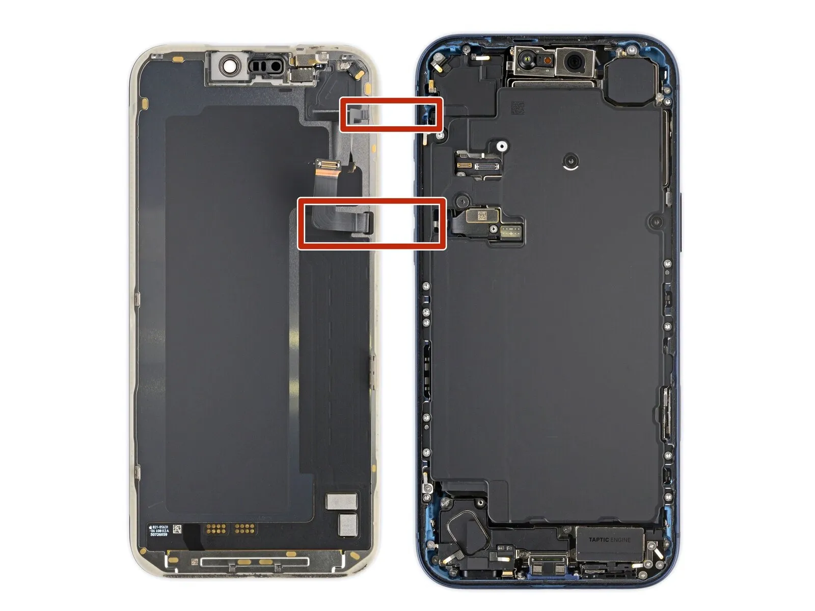
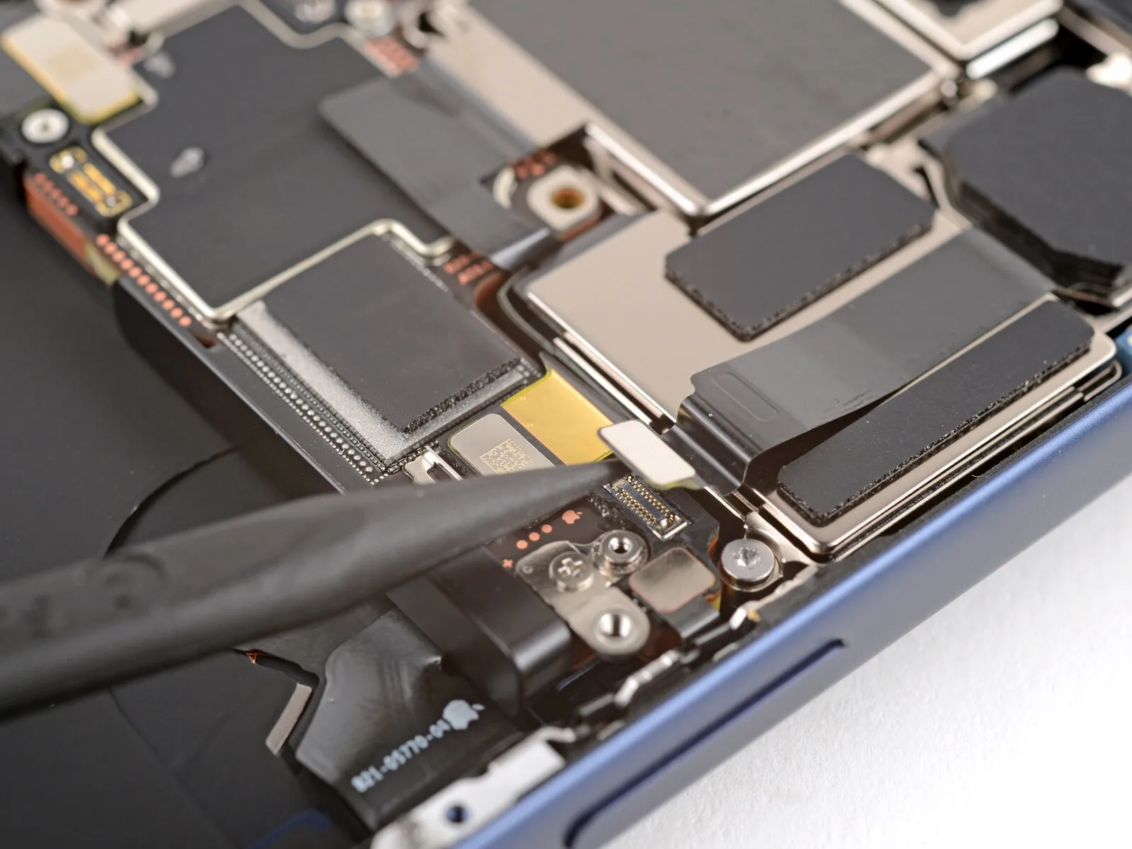
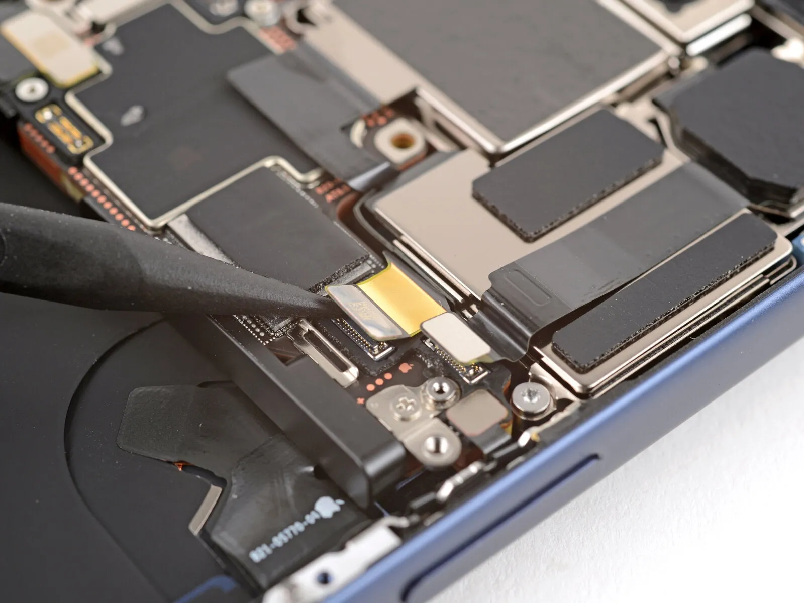
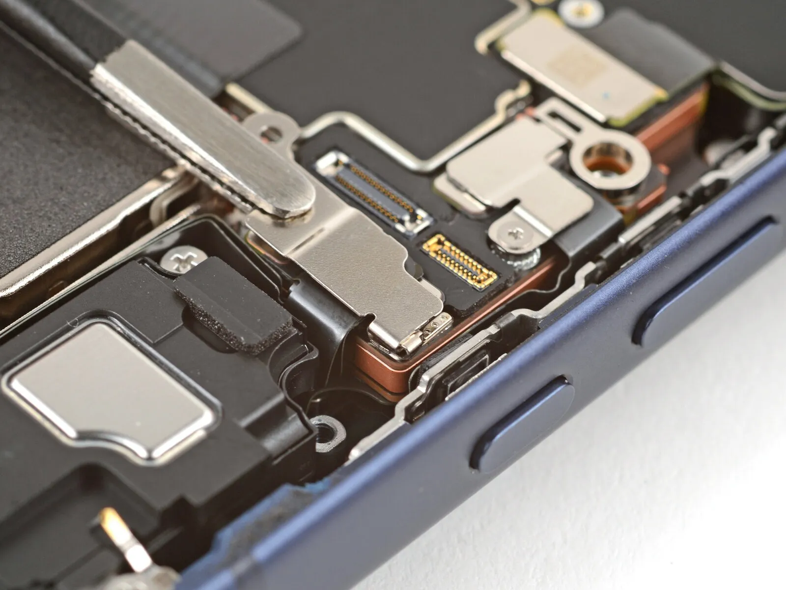
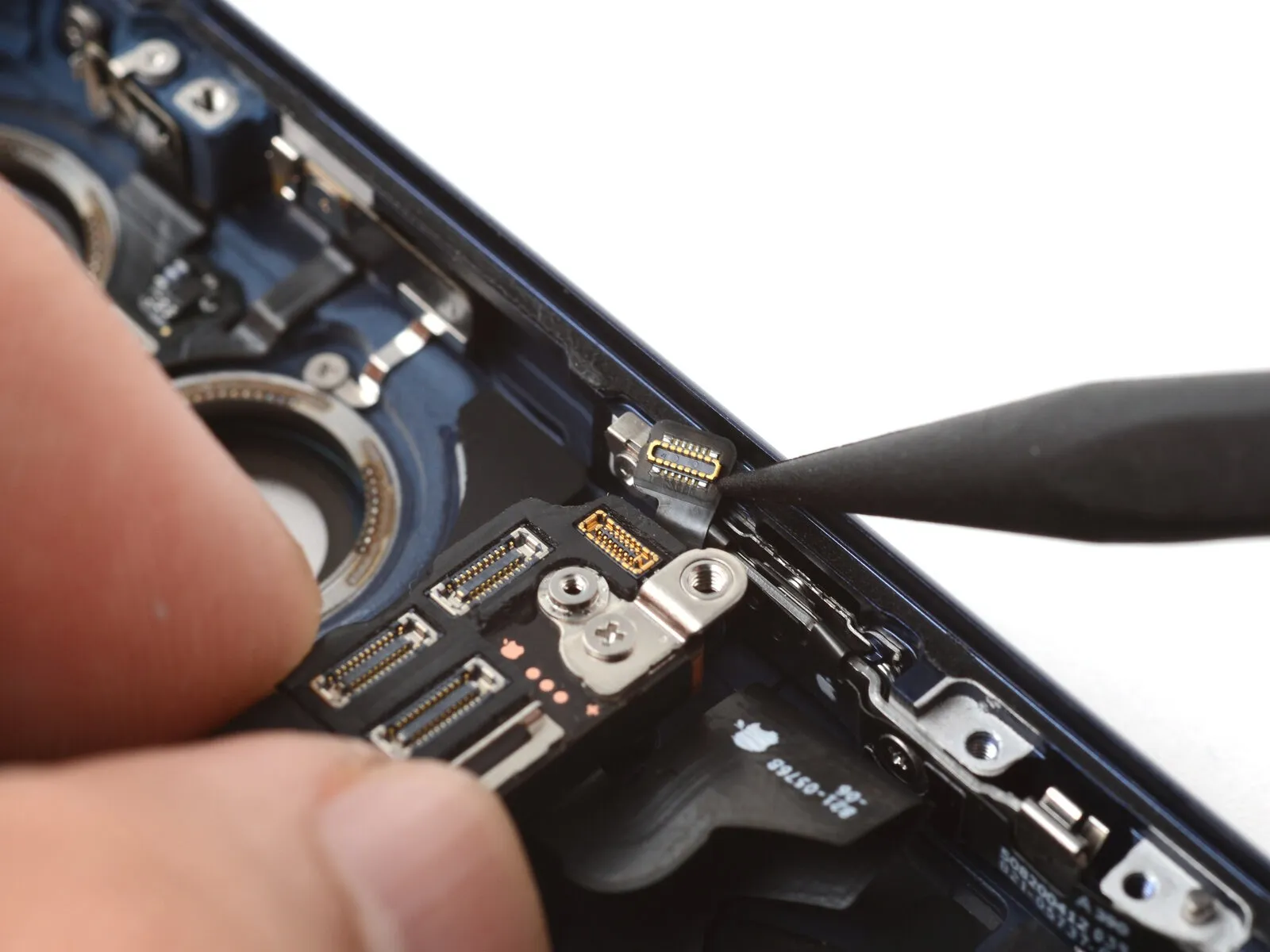
Step 39 | Disconnect the logic board

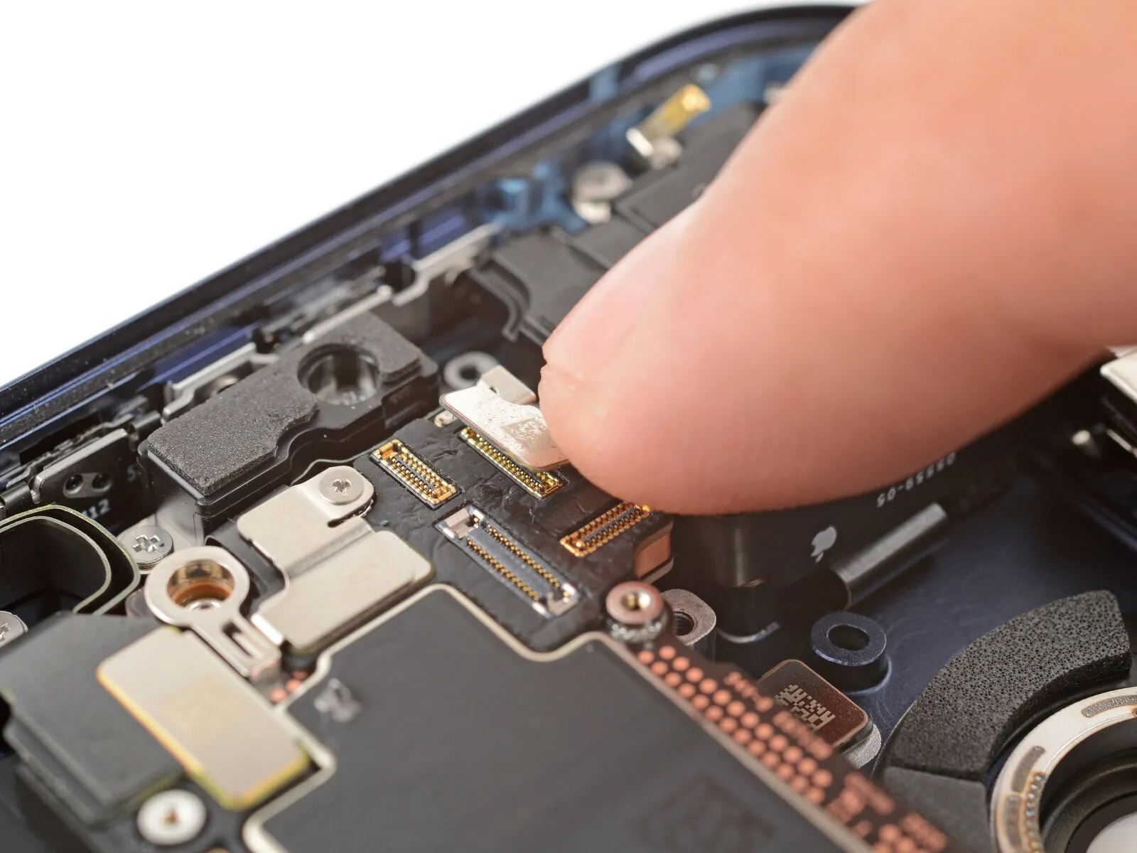
Carefully insert the tip of a screwdriver to.Use a plastic pry tool to gently separate.Using a prying tool, carefully release and separate the two press connectors situated along the upper edge of the logic board.
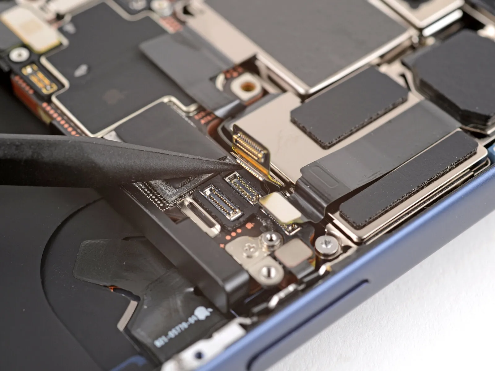
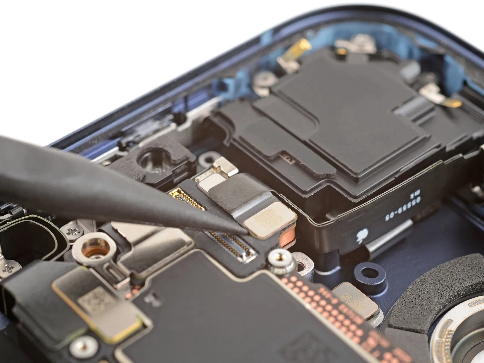
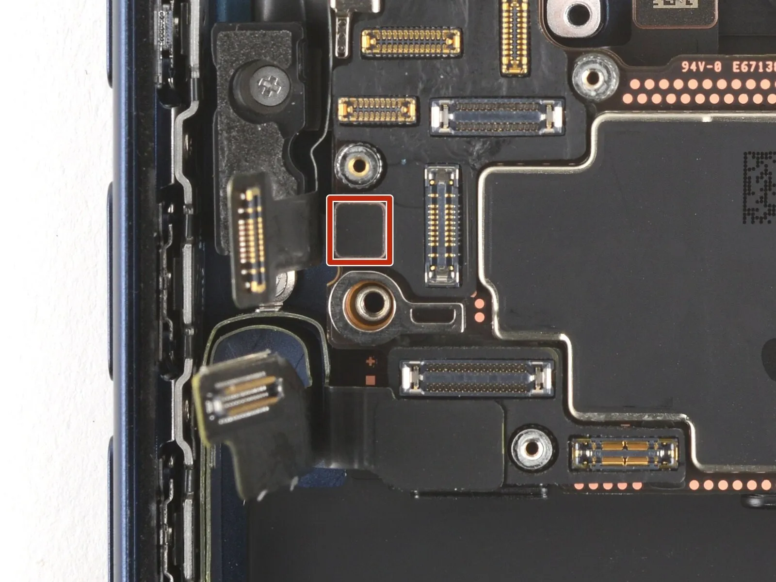
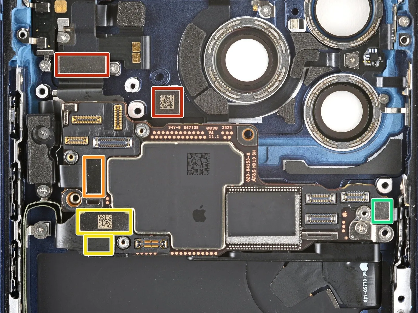
Step 40
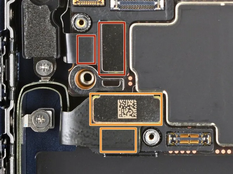
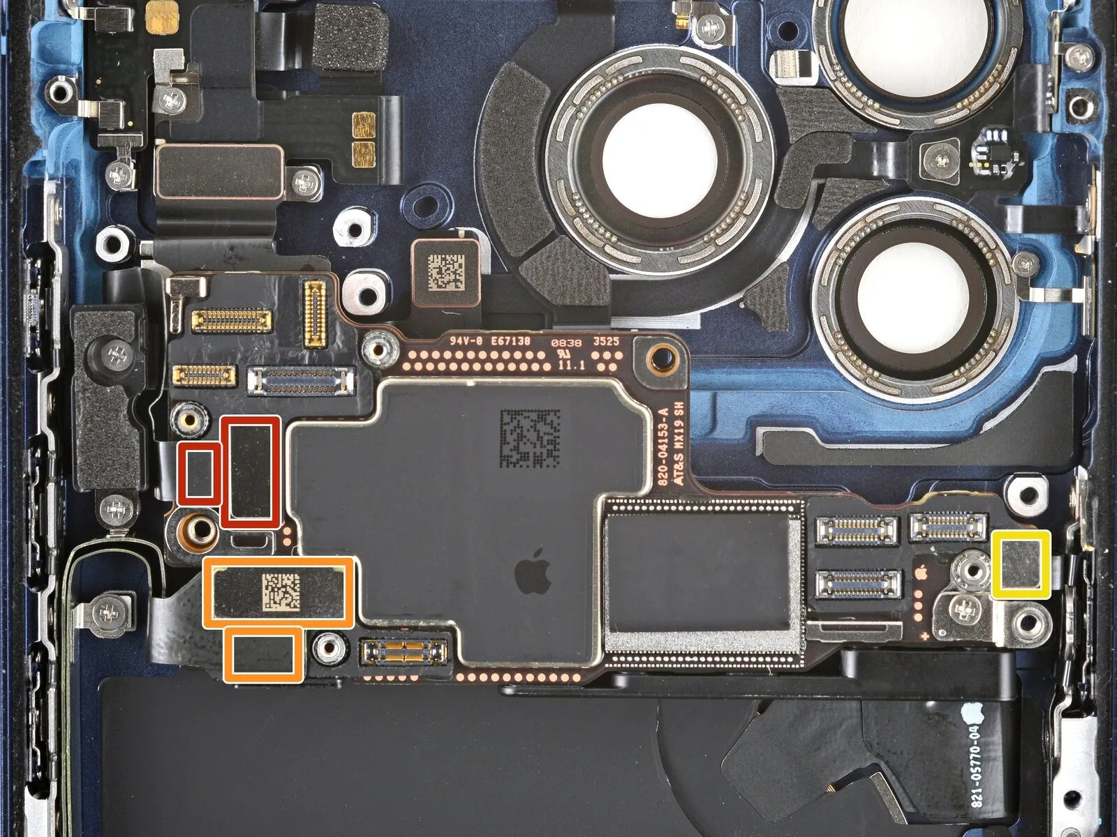
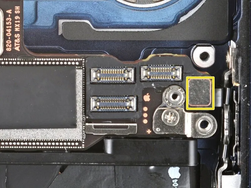
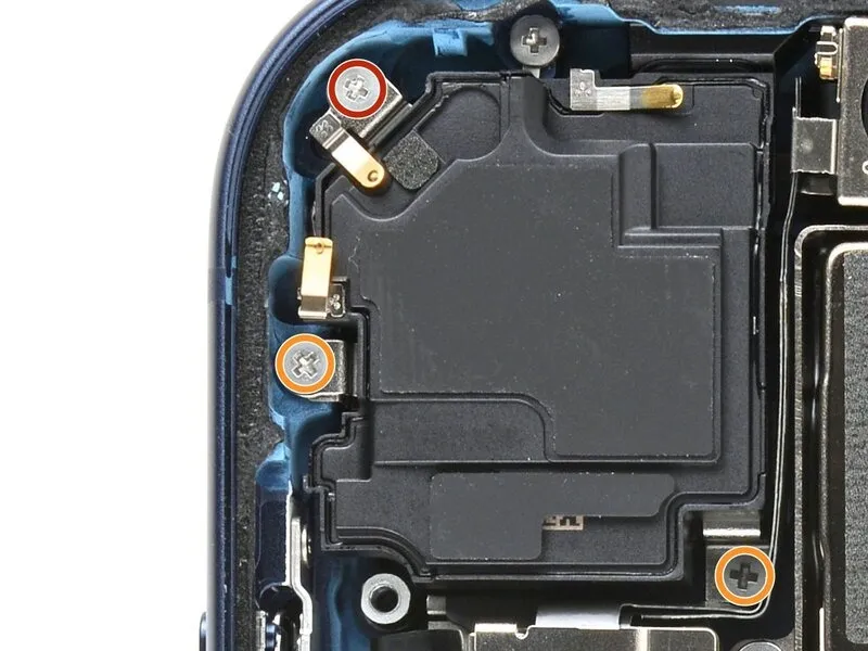
Carefully employ the tip of a screwdriver to apply pressure.Use a plastic pry tool, often referred to as a spudger.Using a prying tool, carefully release and detach the five press connectors affixed to the logic board.
- Beneath the upper connector, you’ll find a second board connector with two buttons.
- The USB-C port assembly incorporates two connectors stacked vertically, with one positioned directly below the other.
- A single connector for the power button.
Step 41

Step 42 | Remove the left logic board buffer

Step 43

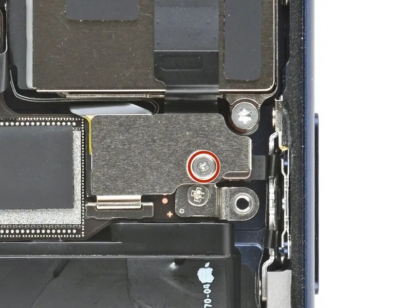
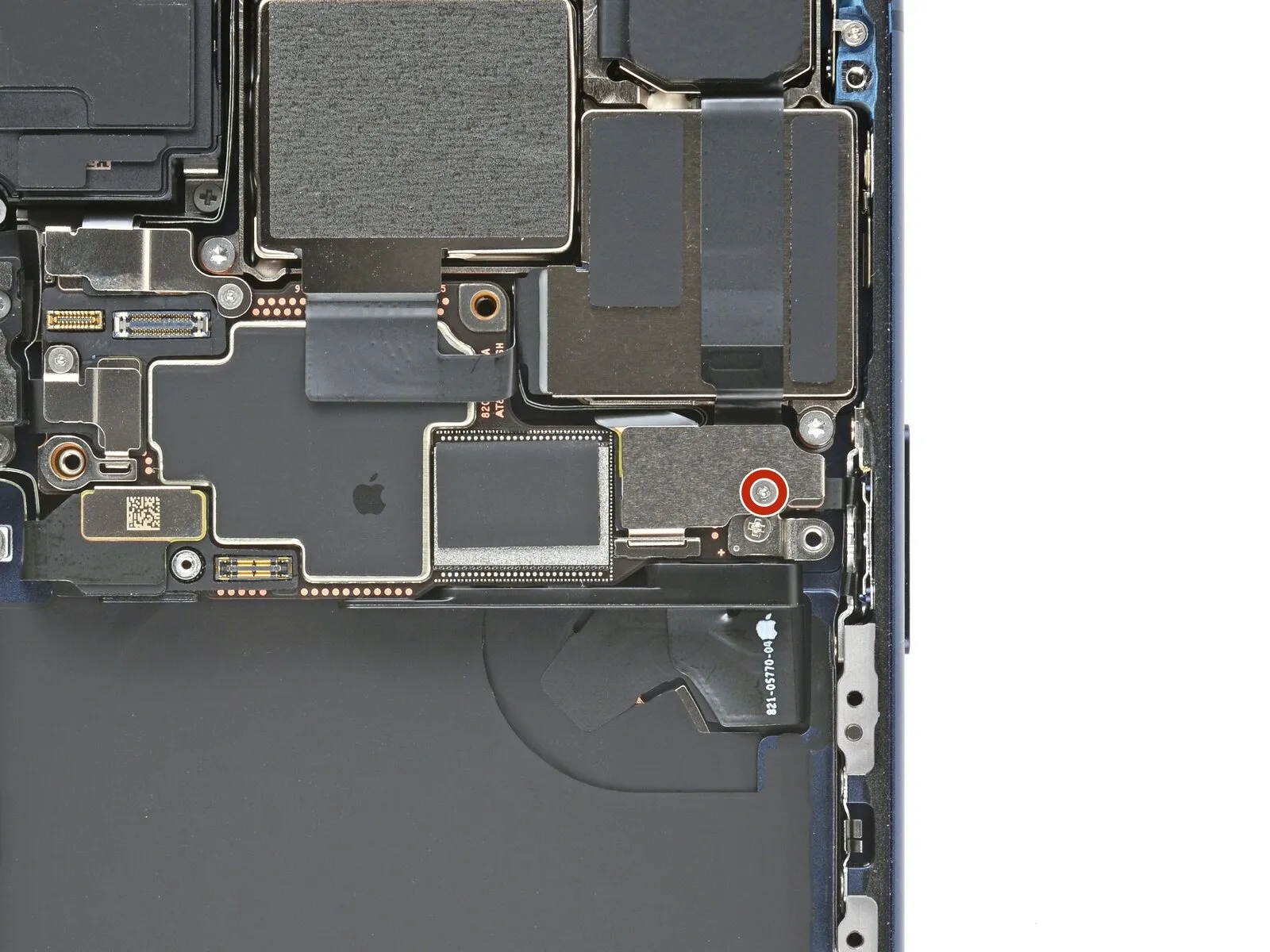
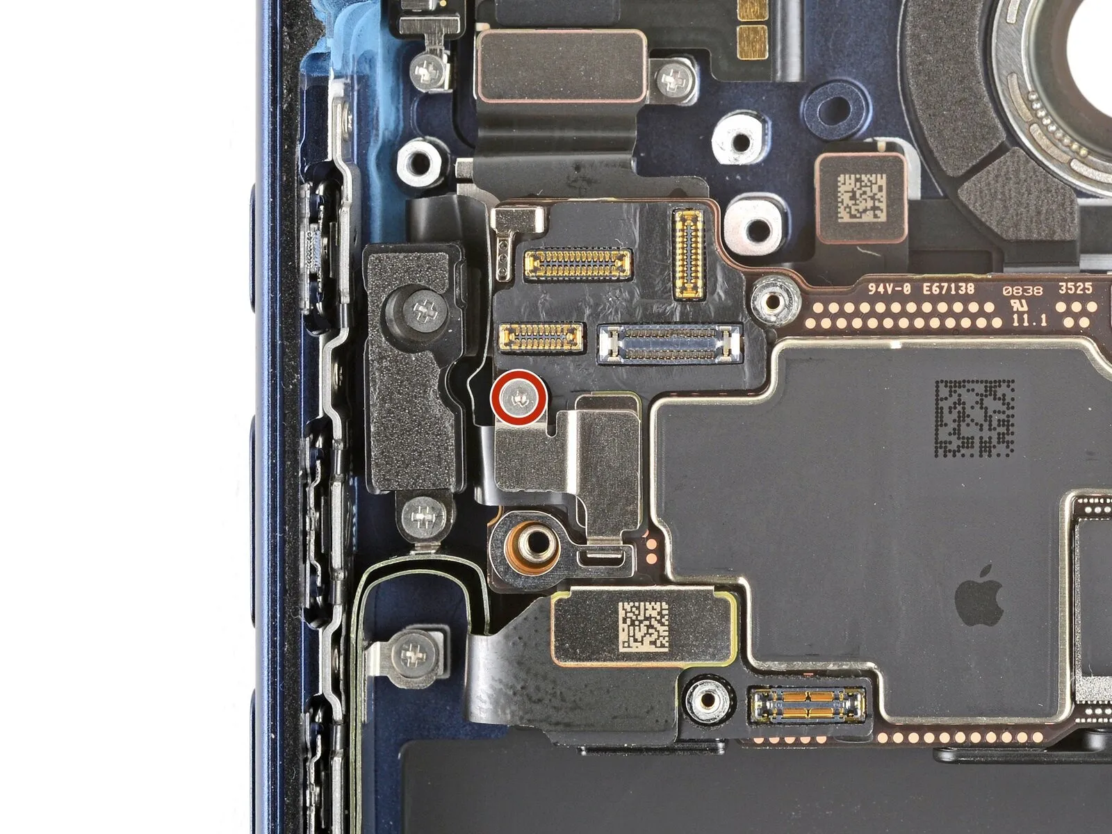
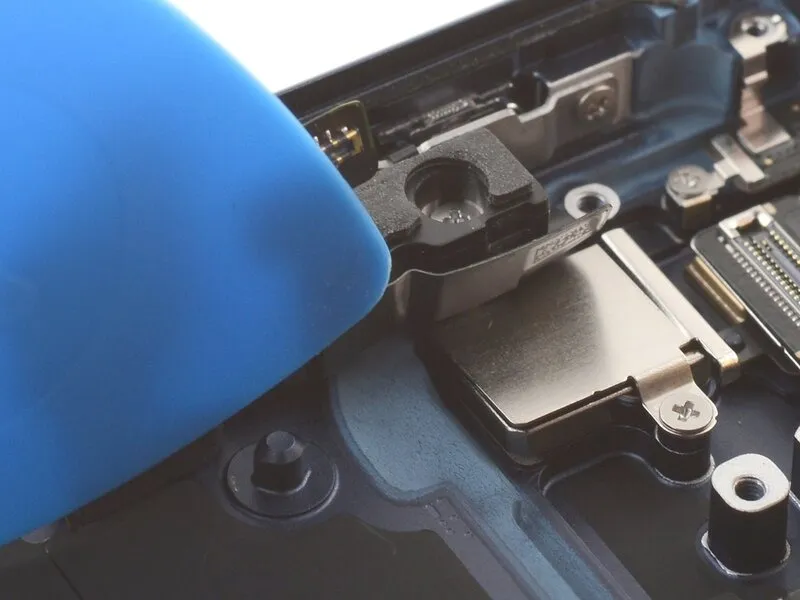
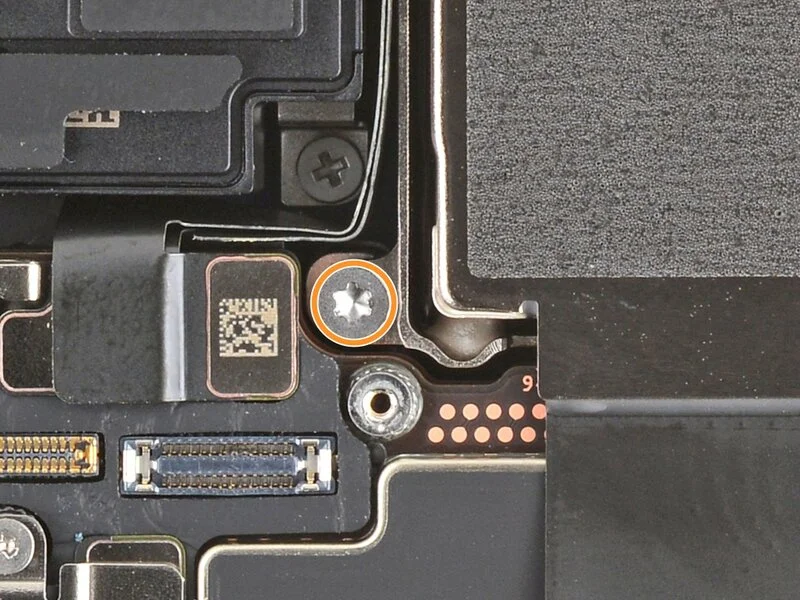
Step 44 | Remove the LiDAR cover
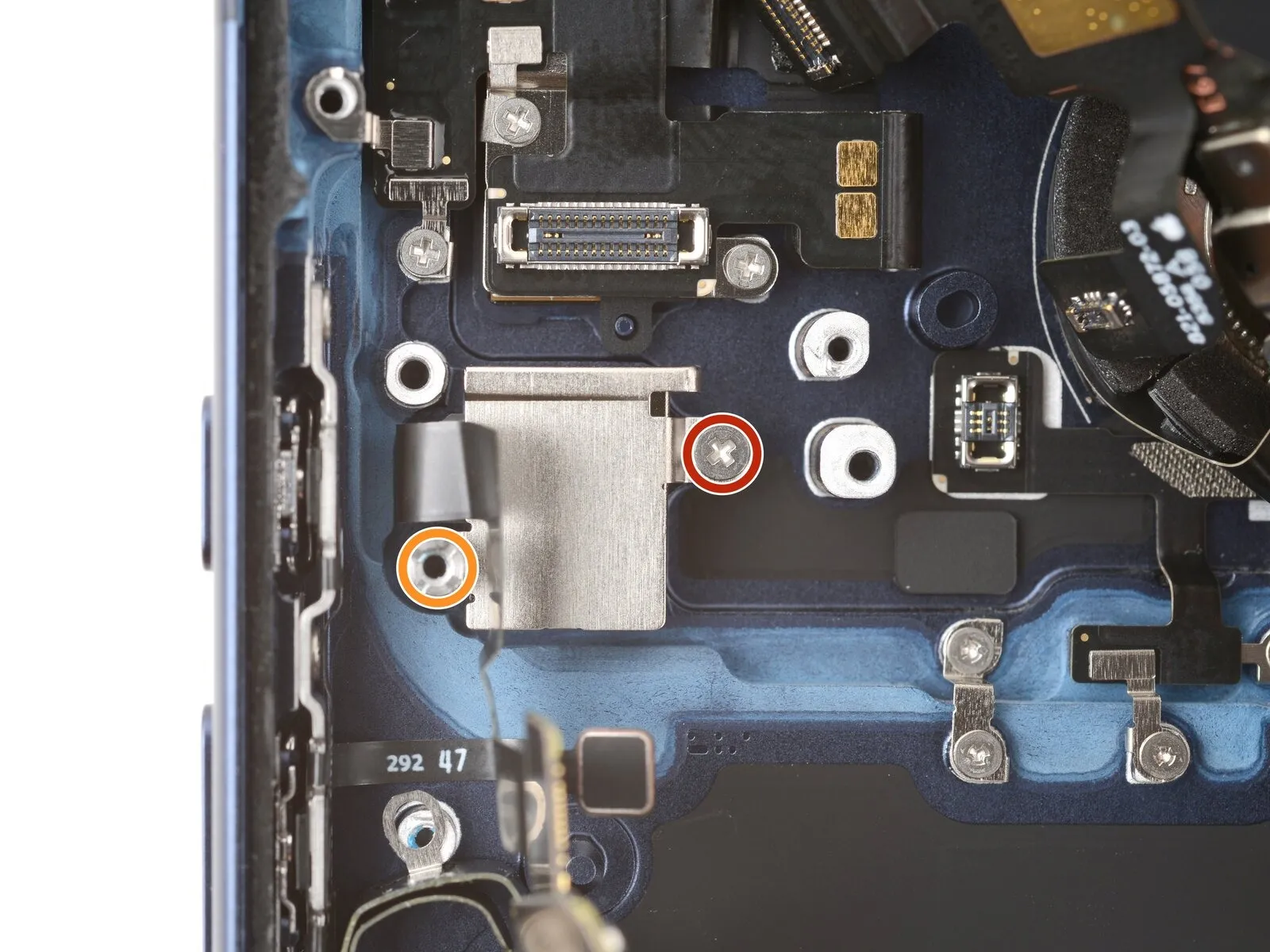
- Begin the process by executing step one.One point seven millimeters.Use a long JIS screwdriver.00Fasten with a screw.
- Begin the process by executing the action designated as "One."The specified dimension is four point eight millimeters.Use the provided long standoff screw.
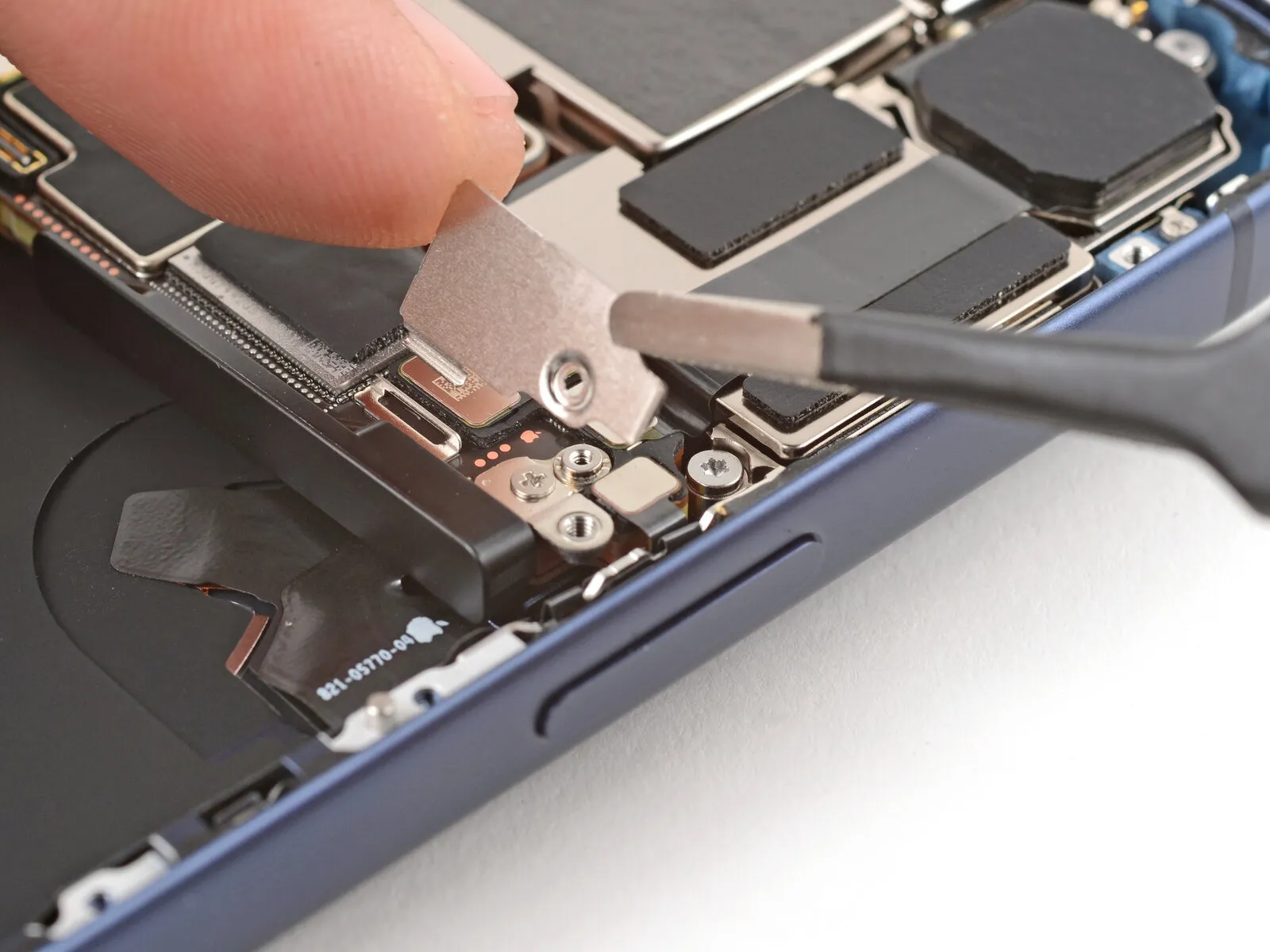
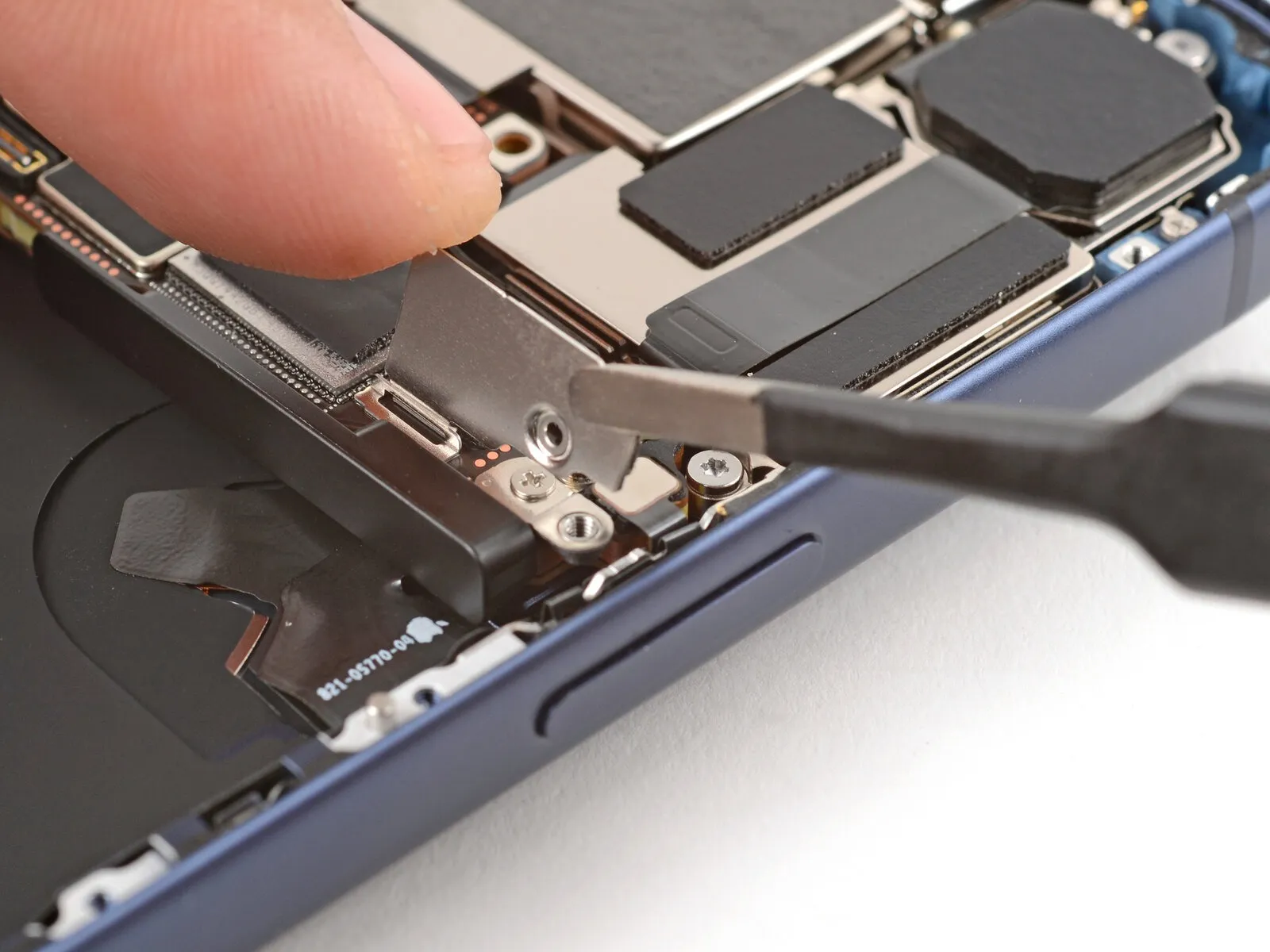
Step 45
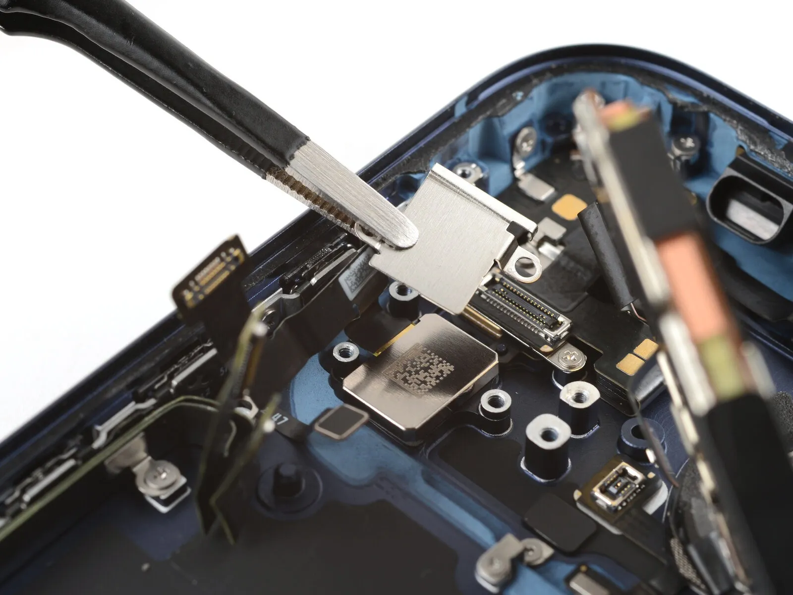
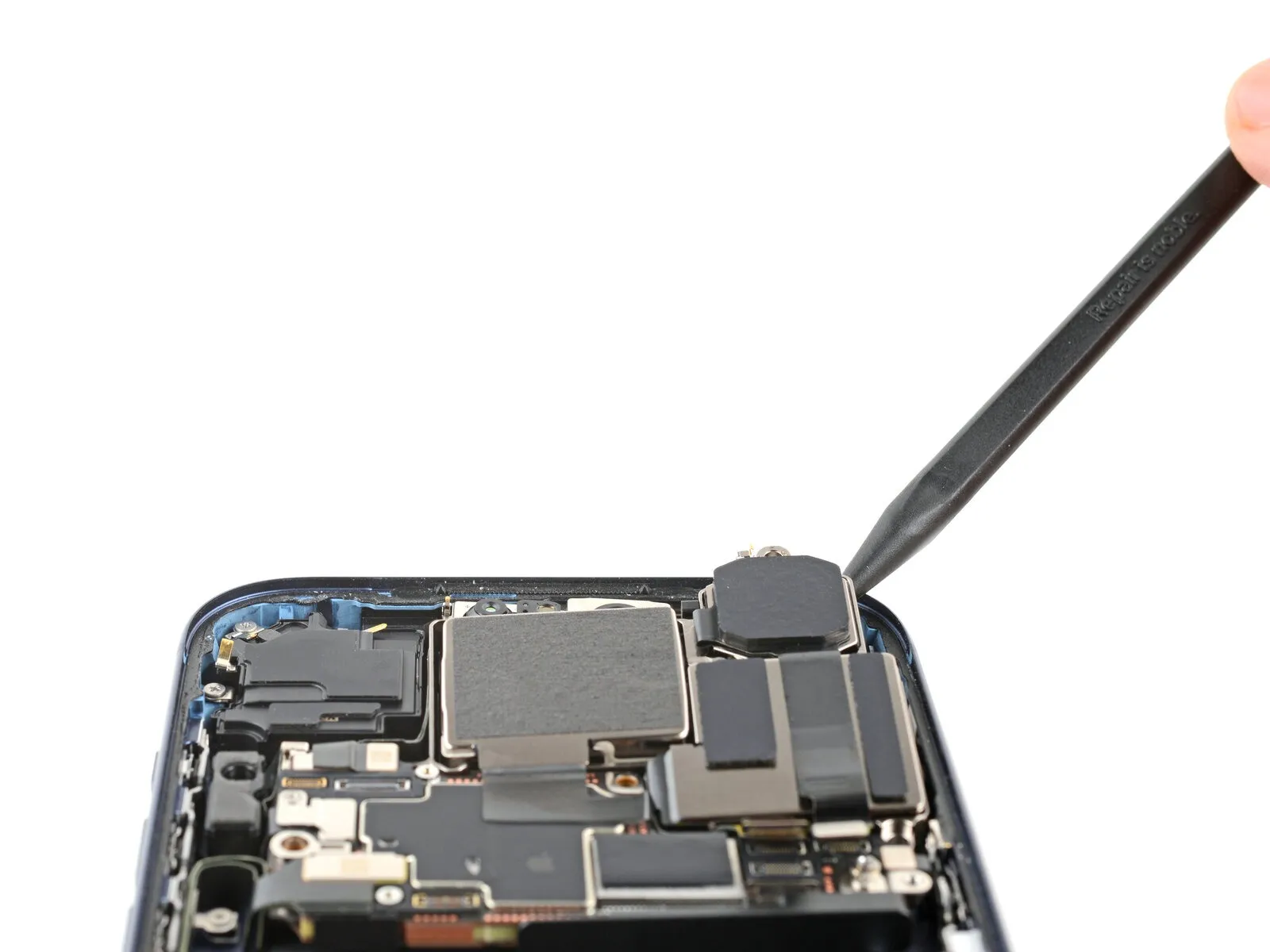
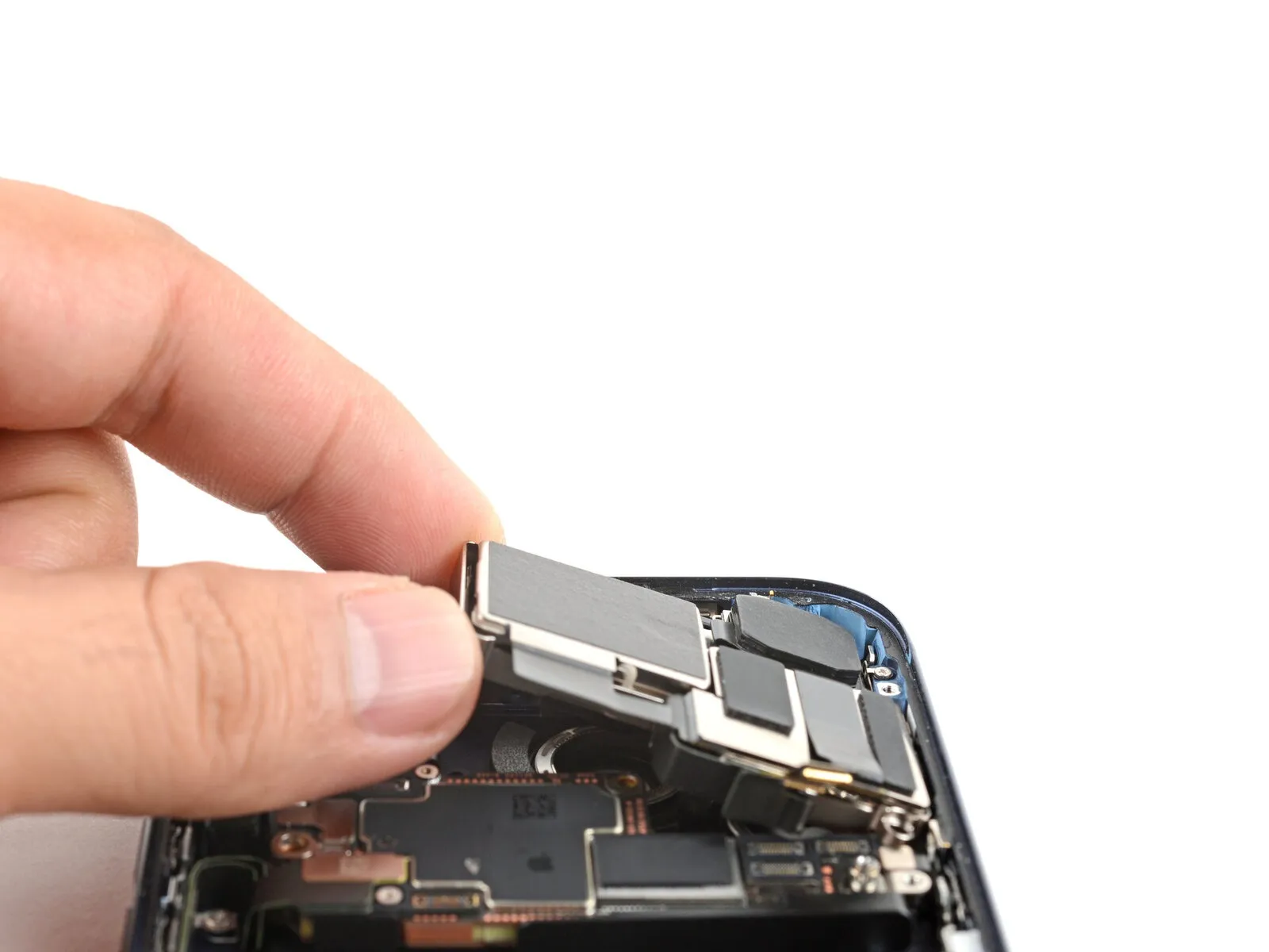
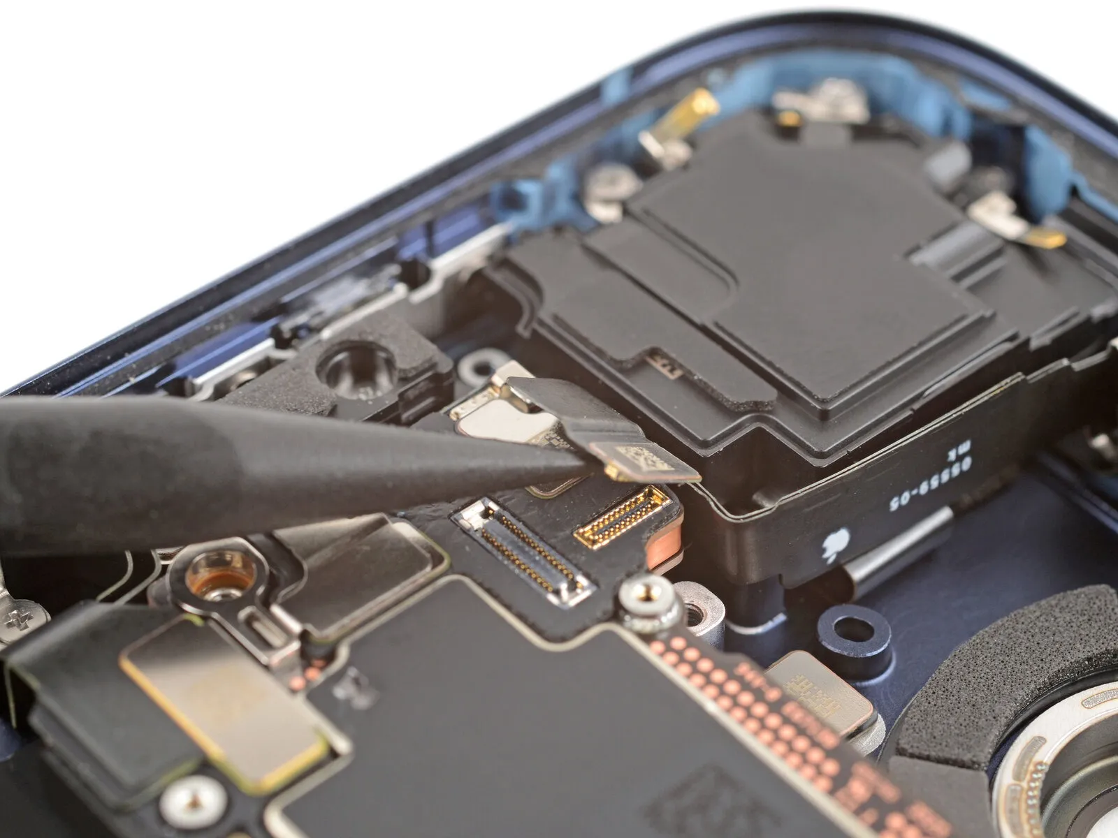
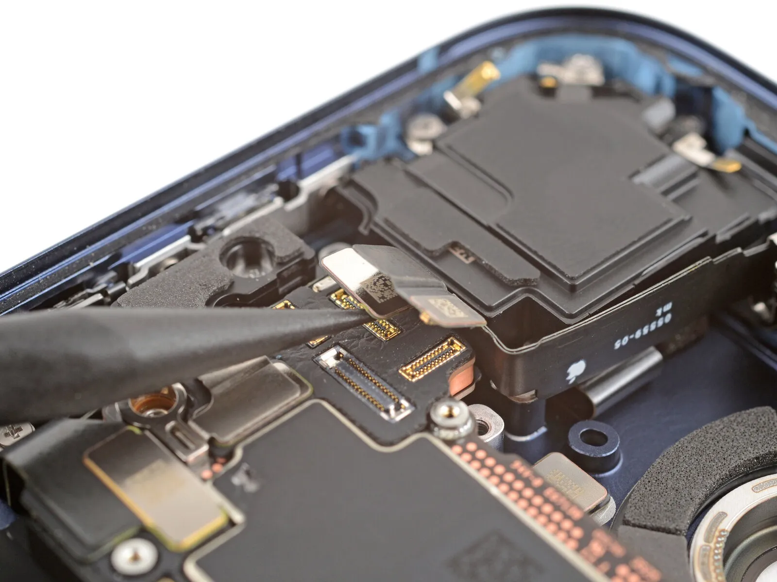
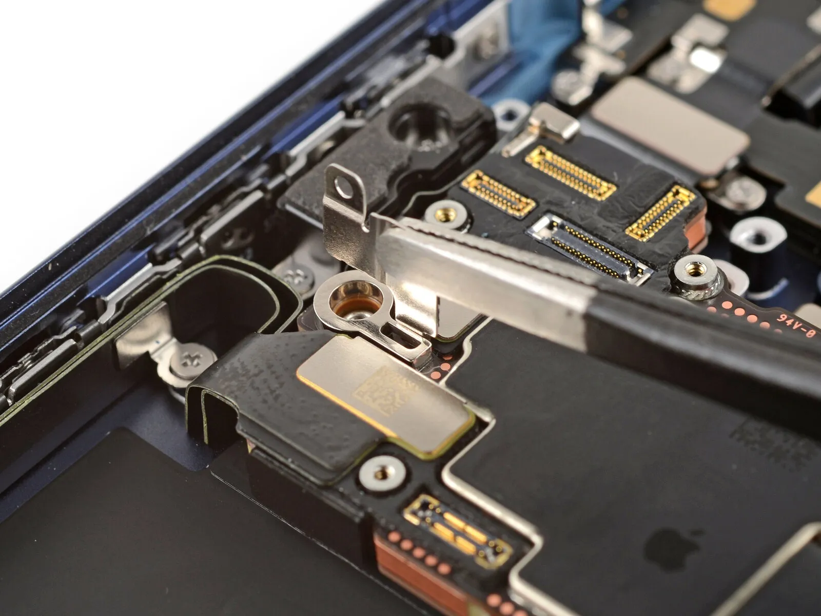
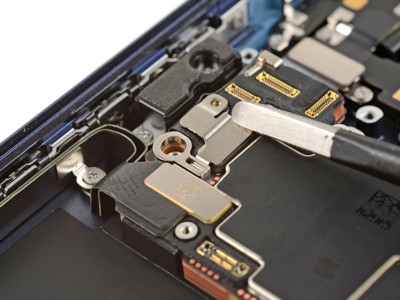
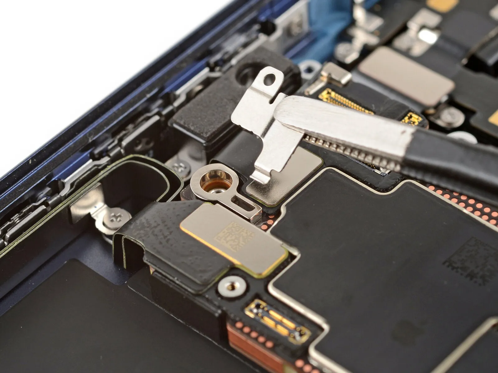
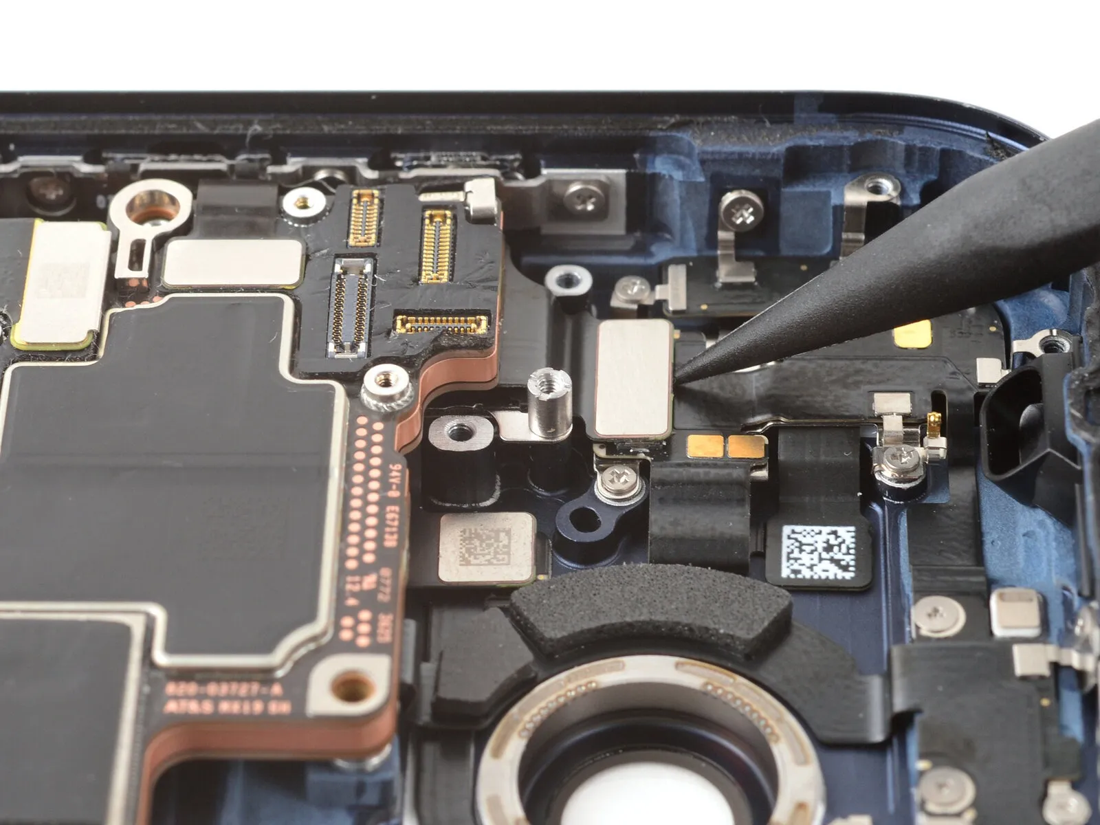
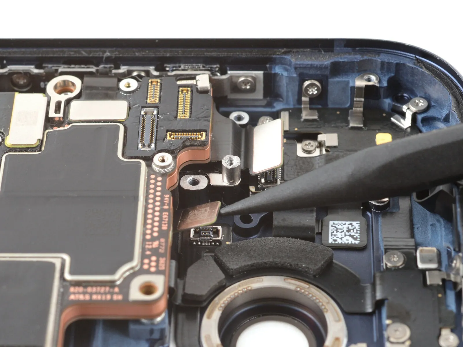
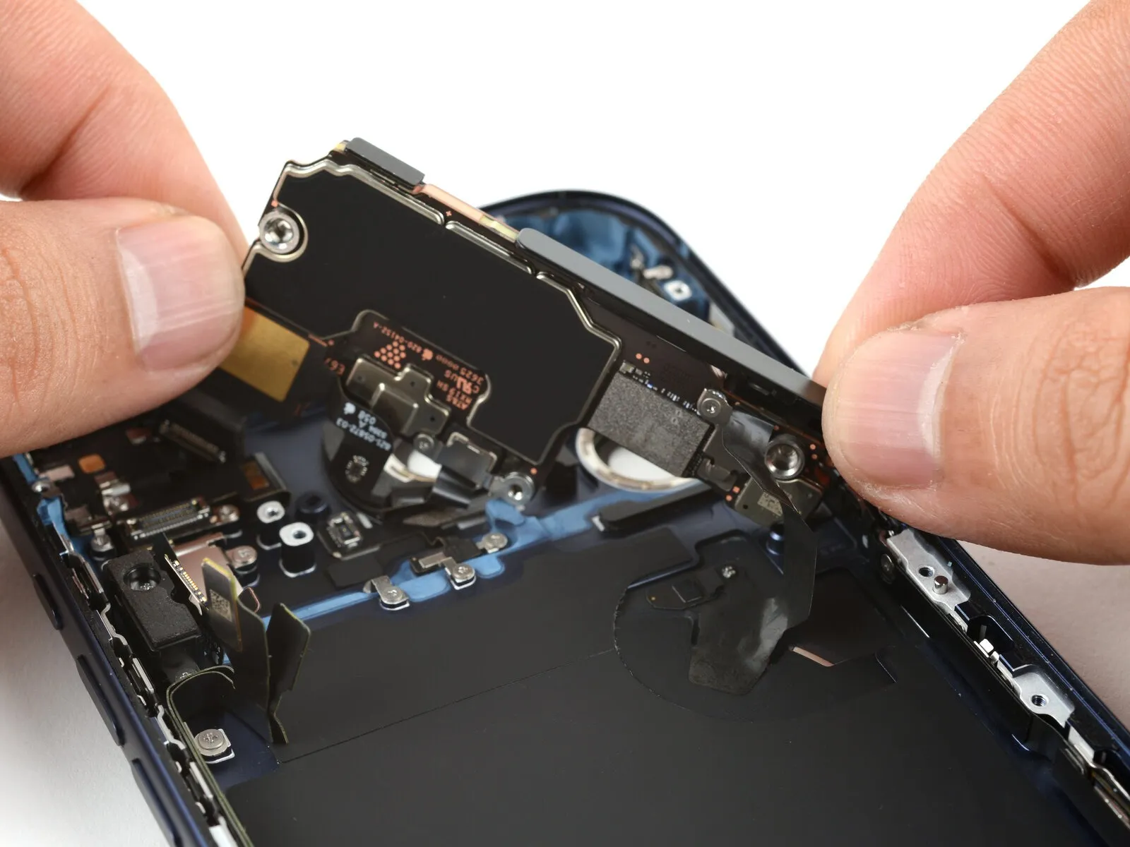
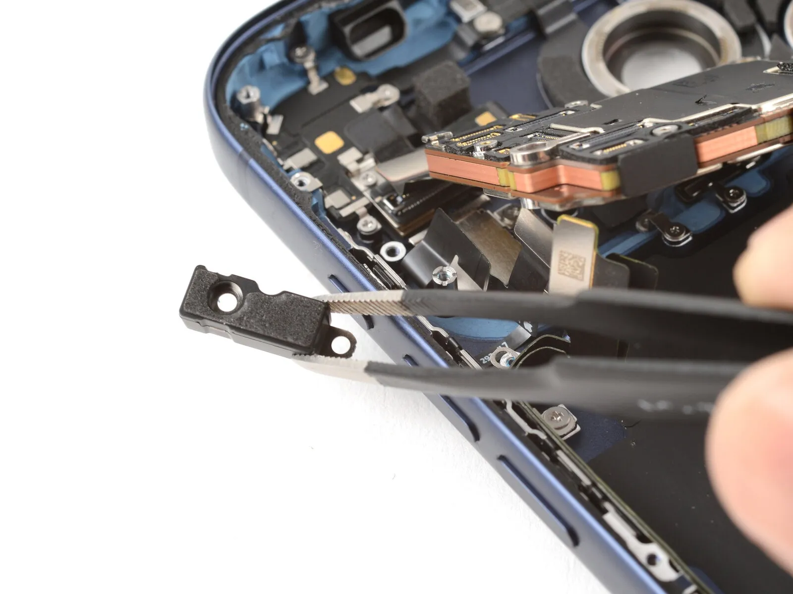
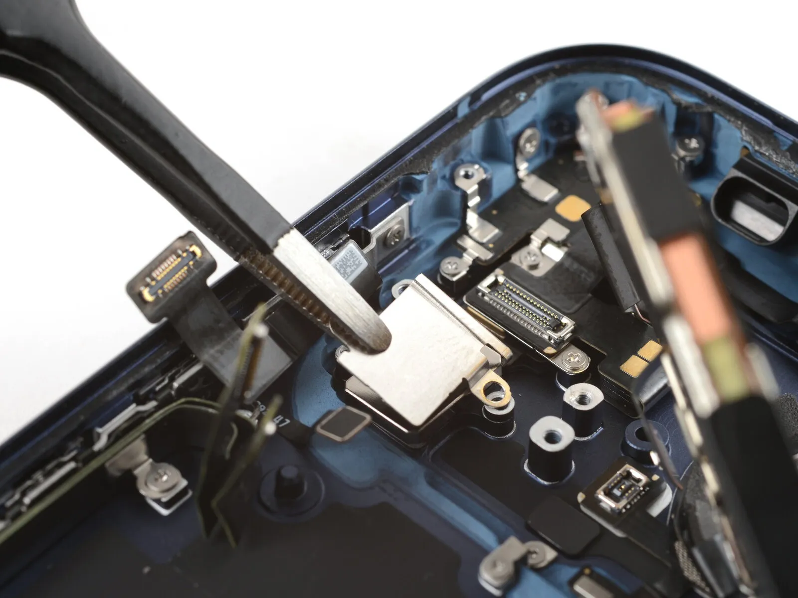
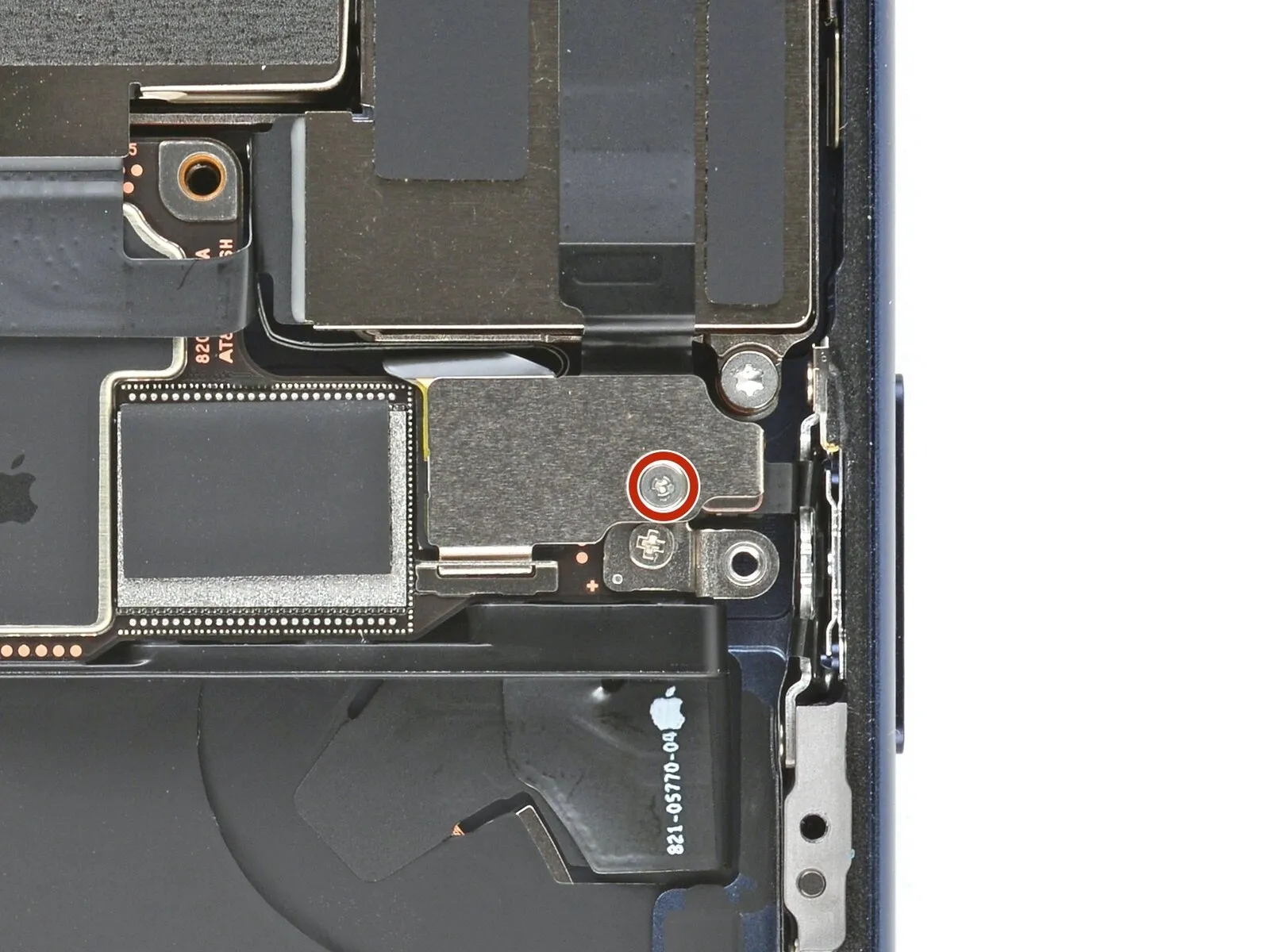
Step 46 | Remove the LiDAR module
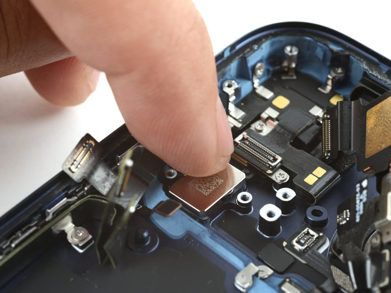
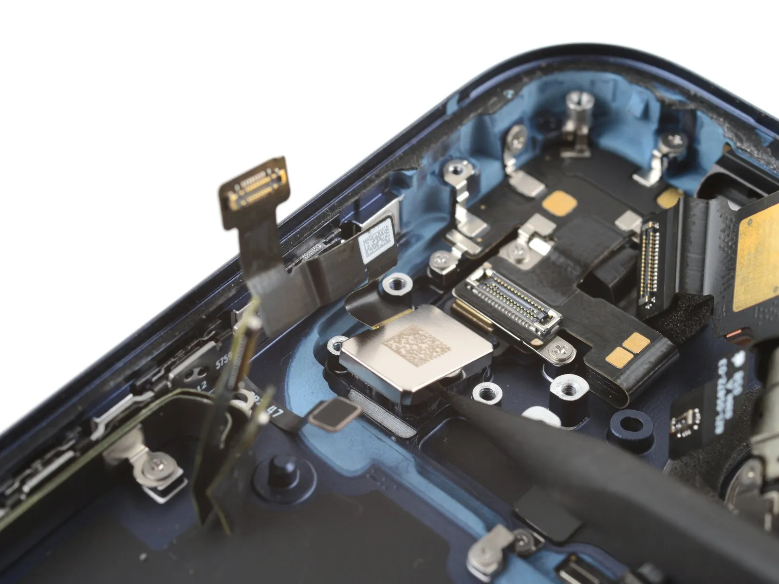
- Carefully employ the tip of a screwdriver to apply pressure.Use a plastic pry tool to gently separate.Carefully use a prying tool to lift one edge of the LiDAR module.
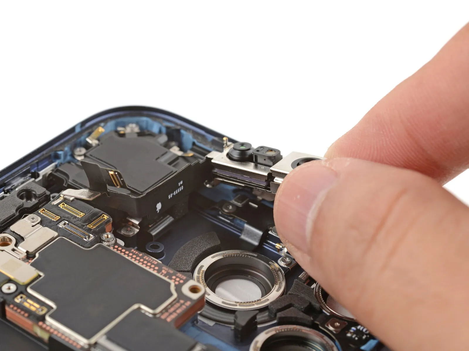
- Carefully detach the LiDAR module by hand.
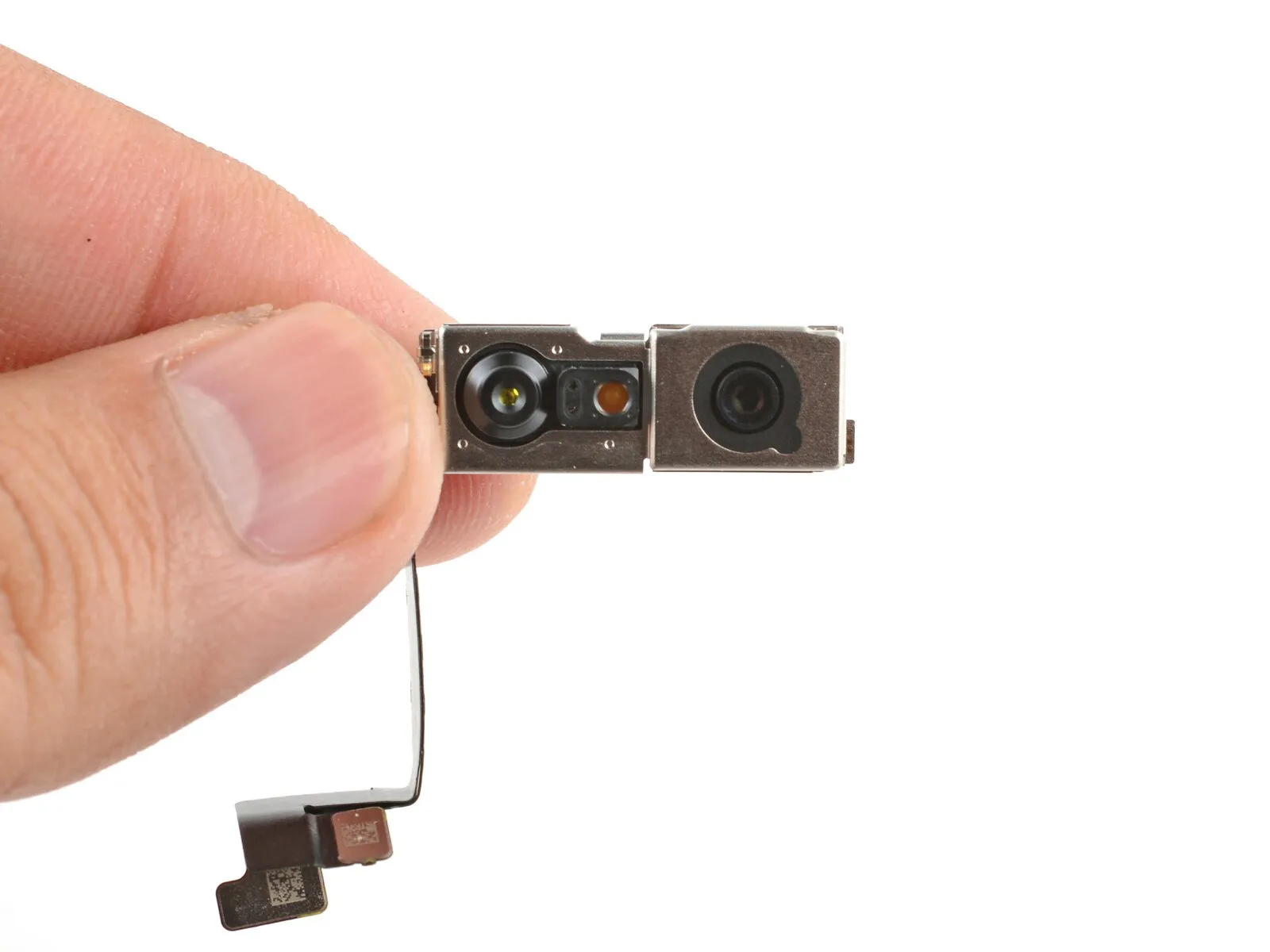
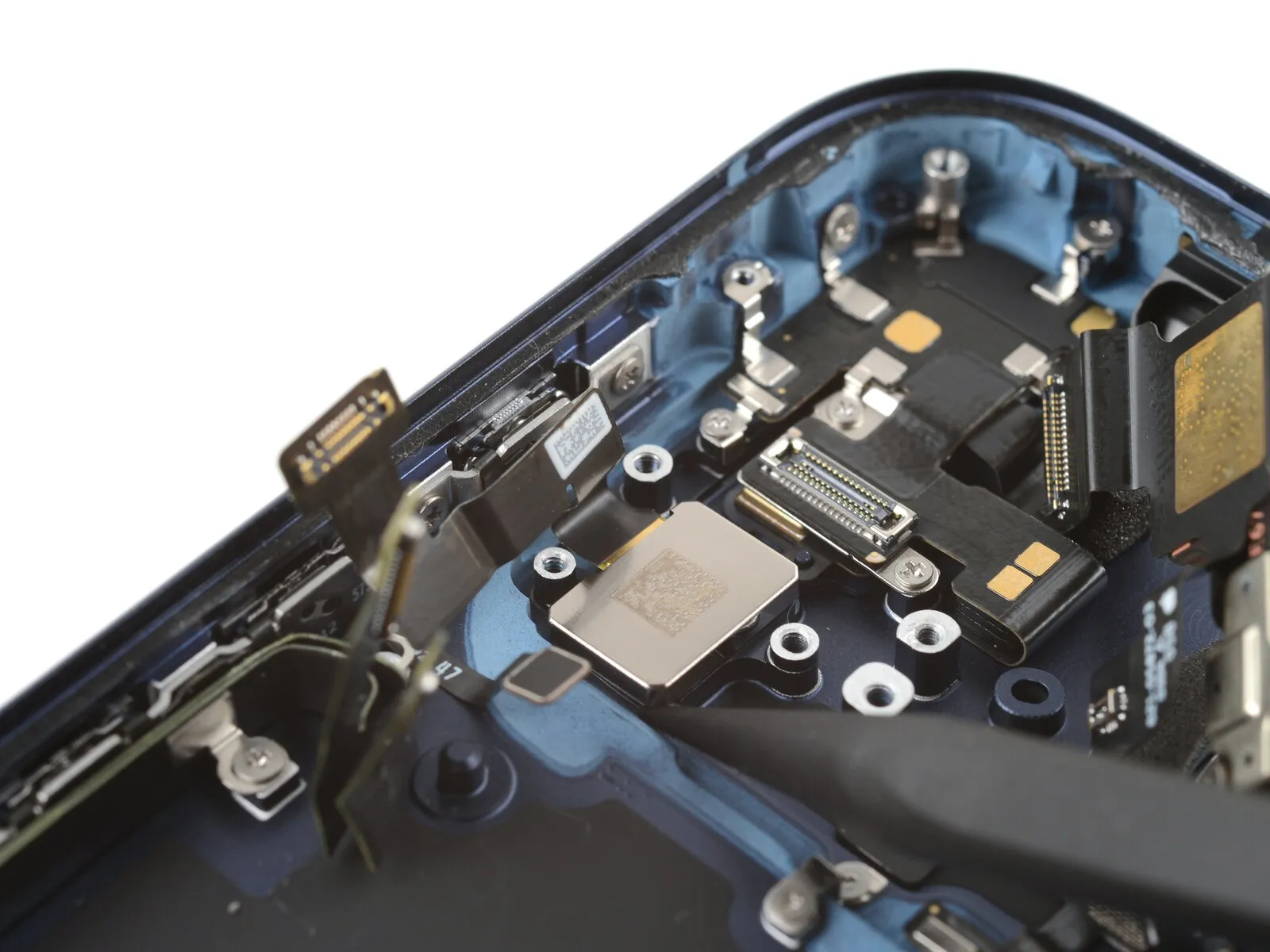
Step 47 | Disassembly complete

With the device now disassembled, proceed with the following instructions to reassemble your iPhone.
Visual differences in the assembly illustrations might occur based on your iPhone's specific version, but the steps remain accurate for all models.
Step 48 | Install the LiDAR module

Carefully position the LiDAR module within its designated cavity, ensuring proper alignment, and apply light pressure to secure it.
Step 49 | Install the LiDAR cover
Position the LiDAR cover directly atop the LiDAR module.
Step 50
Secure the LiDAR cover with the provided two screws.
- Begin the process by executing the singular action.One point seven millimeters.Employ a JIS 00 screwdriver to tighten the long screw.
- Begin the process by executing step one.The required diameter is 4.8 millimeters.Use the provided long standoff screw.
Step 51 | Install the left logic board buffer
Carefully position the left logic board buffer into its designated space using tweezers.
Step 52
Employ a JIS 00 screwdriver for the installation of the two.Eight tenths of a millimeter.Carefully remove the screws securing the left logic board buffer, noting their length.
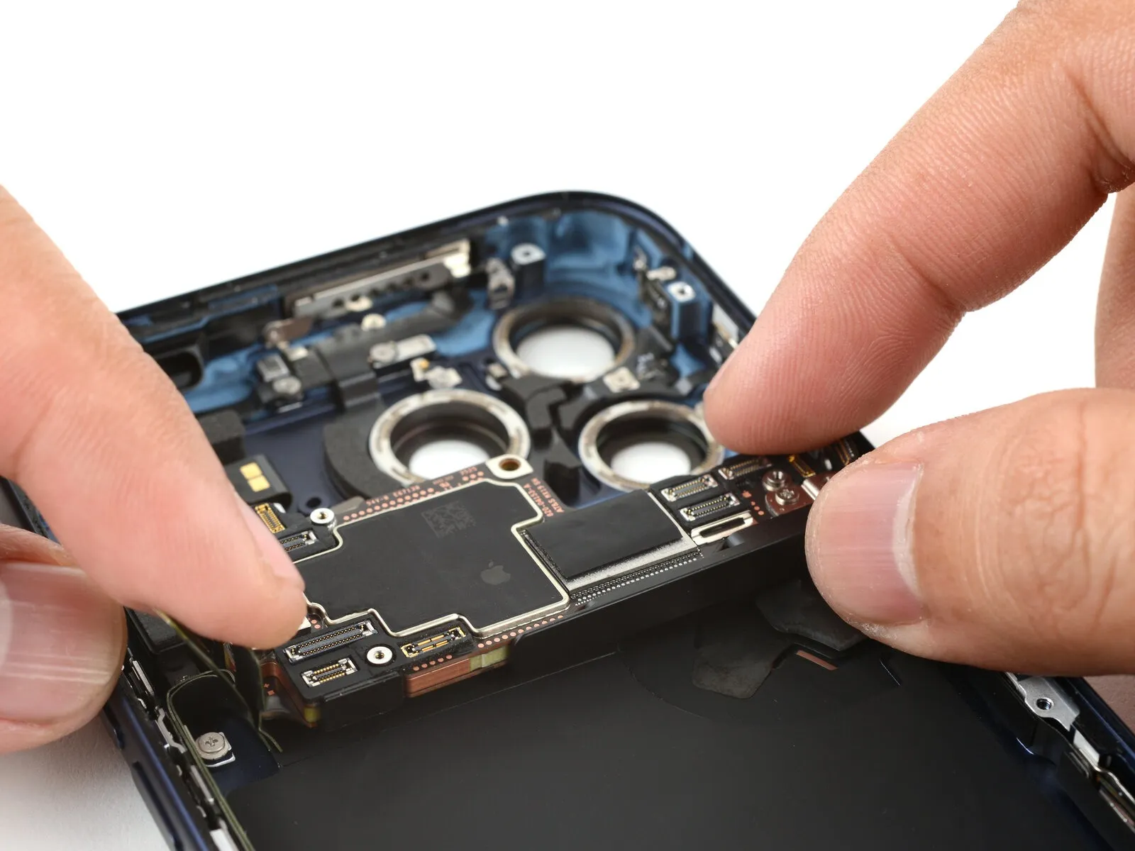
Step 53 | Install the logic board

- Employ a 5/32-inch hex key to loosen the retaining screw, ensuring you maintain a firm grip on the component to prevent movement during the process, and be aware that excessive force could damage the threaded section.Use a specialized tool designed for prying, often referred to as an opening pick.Ensure the flexible cables positioned along the iPhone's left side remain free from obstruction, preventing them from becoming lodged beneath the logic board during reassembly.
- Carefully lower the logic board into position, verifying that the flexible cables on the left and bottom sides aren't pinched or obstructed.
Step 54
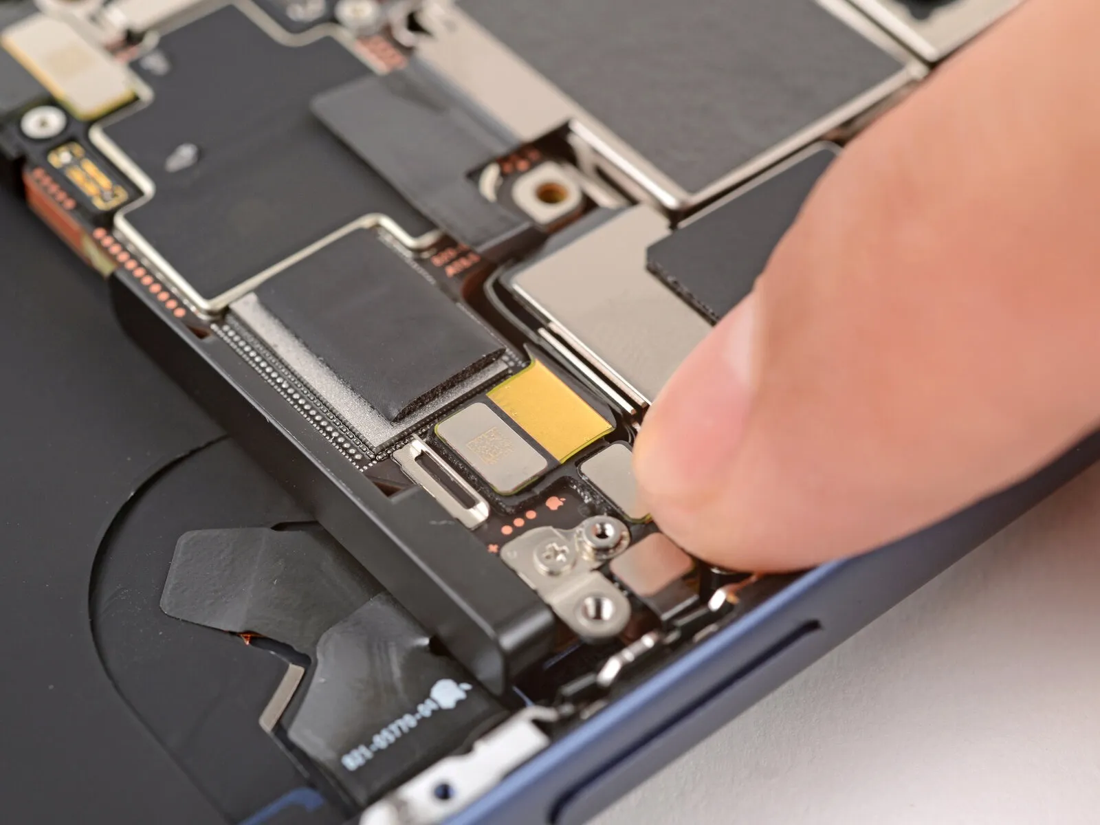
Verify that the power button connector on the logic board's right side isn't pinched or obstructed by the logic board itself.
Step 55
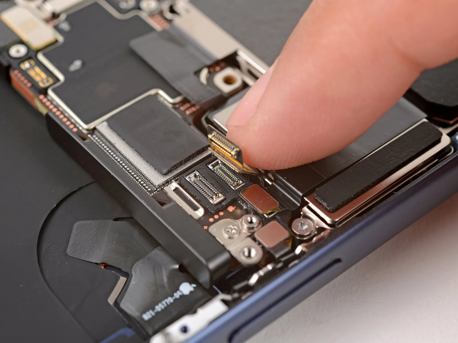
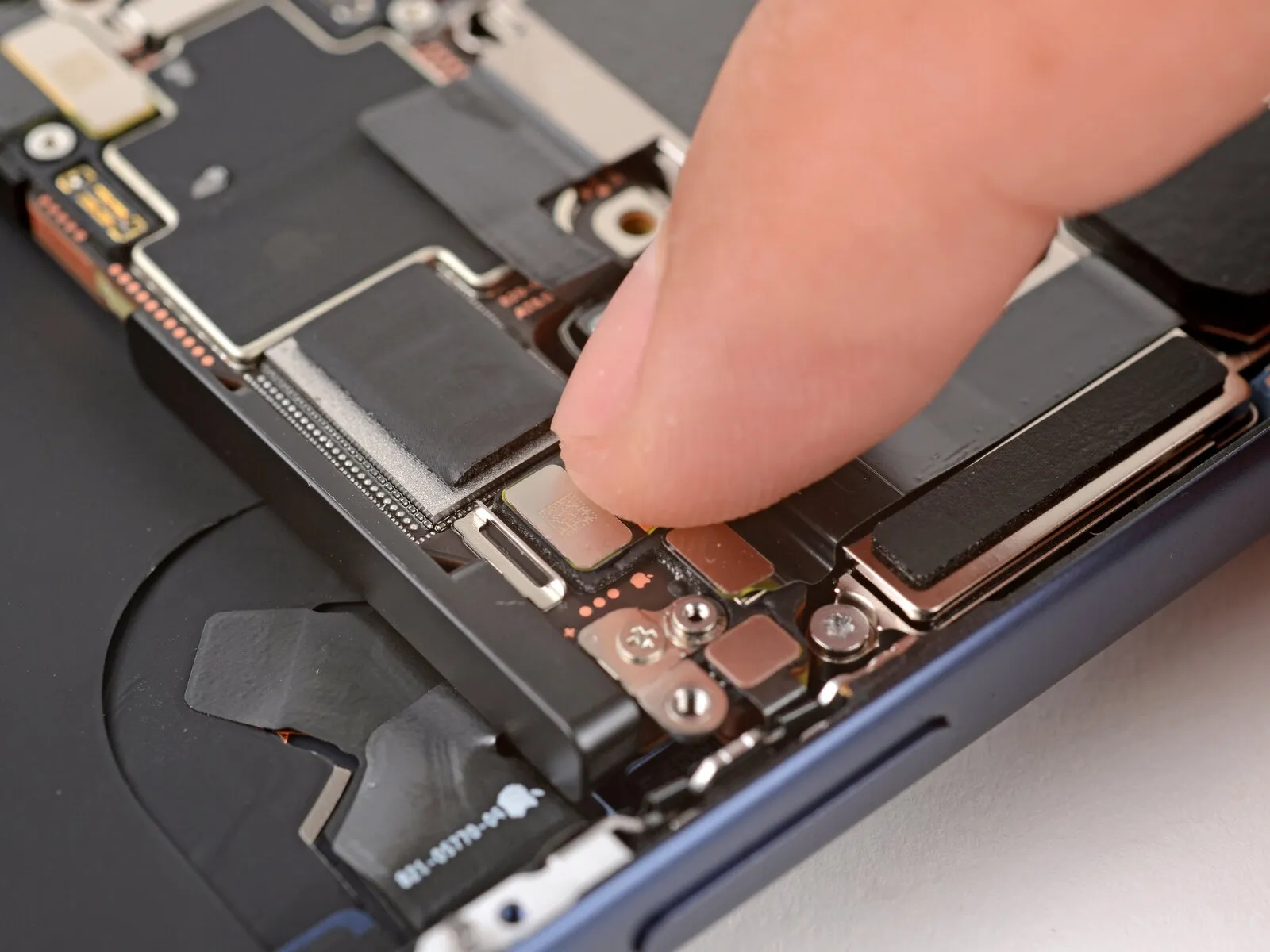
- Employing a fingertip, engage the small button connector located on the logic board's left side by applying pressure to secure its connection.
- If you encounter resistance or difficulty aligning the connector, discontinue the process.Connect the flexible ribbon cable to the button assembly, ensuring the gold contacts align precisely with the corresponding pads on the circuit board.The cable exhibits a common deformation that can obstruct movement beneath the logic board; carefully raise the logic board to release this bend and permit reconnection.
Step 56
- Secure the six components by applying finger pressure to affix them.Apply firm, even pressure to each connector.:
- The logic board features two connectors situated along its upper perimeter.
- A single connector board for buttons remains.
- Stack the two USB-C port assembly connectors, aligning them vertically.
- A single connector secures the power button.
Step 57 | Install the button connector cover
Step 58
Step 59 | Install the top speaker

- Ensure the upper edge of the speaker assembly is flush with the iPhone's top edge.
- Carefully position the speaker within its designated cavity.
Step 60
- Use two.Two point four millimeters.Utilize screws with a length of long.
- Begin the process by executing the action designated as "One."The specified dimension is two point one millimeters.Employ a screw of extended length.
Step 61 | Install the front camera assembly
Carefully position the front camera assembly into its designated cavity.
Step 62


- Carefully join the two components by applying manual pressure.Locate the electrical connections for the front-facing camera module..
Step 63 | Install the front camera connector cover


Secure the camera connector cover by engaging the corner latch with the logic board.
Step 64
Employ a 3/8-inch socket wrench to loosen the retaining bolt, ensuring you apply consistent pressure to prevent damage to the threaded shaft, and then carefully remove the component.Use a Y000 tri-point screwdriver.Secure the component using the specified fasteners, ensuring proper alignment with the designated mounting points and adhering to the torque specification of 8 Newton-meters.A screw, measuring 1.0 mm in length, secures the front camera connector..
Step 65 | Install the rear camera assembly

Step 66
Carefully align and secure the three camera press connectors to the logic board by applying firm, even pressure with your fingertip.
Step 67
- Employ a 3/8-inch socket wrench to loosen the retaining bolt, ensuring you maintain a firm grip and wear safety glasses to protect against potential debris; subsequently, carefully detach the component.Use a screwdriver with a Torx Plus profile and a 4IP size.Secure the rear camera assembly using the three provided screws.
- Two.Screws measuring 4.0 millimeters in length.
- Begin the process by executing action number one.A screw measuring 4.4 millimeters in length.
Align the component with its designated screw aperture and secure it.
Step 68 | Install the rear camera connector cover
Carefully position the rear camera connector cover onto the logic board, securing it with tweezers.
Step 69
Employ a 3/8-inch socket wrench to loosen the retaining bolt, ensuring you maintain a firm grip and avoid excessive force to prevent damage to the threaded section, and then carefully remove the component.Use a Y000-sized screwdriver with a three-pronged tip.Secure the component using the specified fasteners, ensuring proper alignment as indicated by the manufacturer's measurements and employing the appropriate tools while observing all safety warnings.The camera connector is secured with a screw measuring 1.0 mm in length..
Step 70 | Install the battery
- Position the battery tray correctly within its designated area.
- Ensure all wires and cables remain clear of the tray's underside during reassembly.
Step 71 | Install the battery tray screws
- Employ a 3/8-inch socket wrench to loosen the retaining bolt, ensuring you apply consistent pressure to avoid damaging the threaded shaft, and subsequently, carefully remove the component.Use a screwdriver with a Torx Plus profile and a 4IP size.Secure the battery tray with the provided screws.
- Begin the process by executing the action designated as "One."A screw measuring 7.5 millimeters in length.
- Begin the process with the number one.A screw measuring 5.9 millimeters in length.
- Begin the process by executing action number one.A screw with a length of 3.5 millimeters.
- Begin the process by executing action number one.A screw measuring 2.4 millimeters in length.
- Ten.Screws measuring 3.7 millimeters in length.
- Begin the process by performing action one.A screw measuring 3.7 millimeters in length.
This screw is absent from iPhone versions that utilize a physical SIM card.
Step 72 | Clean the frame
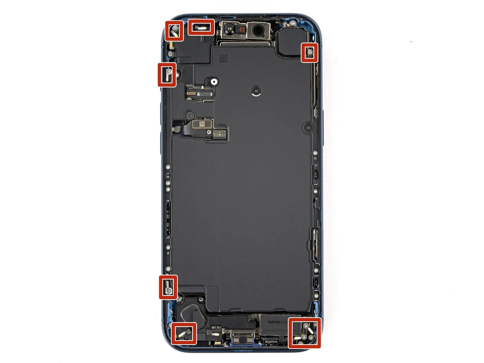


- Exercise caution while cleaning the frame to avoid damaging the delicate grounding clips; should one become displaced, carefully restore it to its original position using your fingers or tweezers.
- Carefully detach substantial adhesive remnants from the frame's edges, employing either tweezers or your fingertips.
- Carefully remove adhesive remnants from the frame's surface using a spudger.
- To loosen a firmly bonded adhesive, direct warm air from a hair dryer or heat gun onto the area and reattempt separation.
Step 73

- Carefully dispense a small quantity ofEmploy isopropyl alcohol with a purity exceeding 90%.Carefully remove any remaining adhesive using a plastic scraper and isopropyl alcohol.
- Carefully clean any residue from the frame's edges by wiping with a microfiber or lint-free cloth, moving the cloth in a single direction. This meticulous cleaning step is important because a clean surface allows the replacement adhesive to spread uniformly, resulting in a stronger bond.
Step 74 | Clean the screen

Before reinstalling a previously used display, carefully dispense a small quantity of adhesive.Employ isopropyl alcohol with a concentration exceeding 90% to ensure maximum potency.Using a microfiber cloth or one free of lint, clean the edges to ready the surface for the application of fresh adhesive.
Step 75 | Orient the replacement adhesive


- Before removing any protective film, position the adhesive sheet onto the frame to confirm correct alignment, referencing the camera opening and the notches located on the upper and lower borders to ensure proper placement within the frame.
Step 76 | Apply the replacement adhesive

Carefully lift a corner tab on the adhesive backing to reveal approximately one-third of the adhesive surface; exercise caution as the exposed adhesive possesses a high tack and should remain free from contact with other surfaces until application to the frame.
Remove the protective layers from the adhesive until the surface designed to bond with the frame is revealed.
Step 77


After ensuring proper alignment, firmly apply pressure to secure the adhesive.The component's location is fixed.To correct the adhesive, detach the existing strip entirely and replace it. Ensure the fresh adhesive strip’s edge is precisely matched to the iPhone frame’s edge, then apply even pressure across the strip to secure it.
Step 78


Carefully apply the adhesive by peeling back the liner while ensuring it adheres smoothly; proper alignment will result in seamless edge placement. Should minor misalignment occur, gently adjust the longer edges to match the frame. Creasing or wrinkling indicates improper application, necessitating removal and replacement with a fresh adhesive strip. If replacement strips are unavailable, the iPhone can be reassembled and used temporarily without adhesive, but be aware that this will reduce its water resistance until a new adhesive is installed.
Step 79

Carefully apply pressure along the iPhone's edges with a spudger to release the adhesive, being mindful of the delicate grounding clips; if any of these clips become dislodged, carefully reposition them using your fingers or tweezers.
Step 80


Carefully detach the large front adhesive liner by grasping the pull tab, typically found at a corner, and peeling it away. Remaining liners along the edges should be left in place for now, as they protect the adhesive surface during reassembly of your iPhone and prevent unintended adhesion.
Step 81 | Connect the screen

Step 82


- Gently push the two components together, ensuring a secure connection, utilizing either a fingertip or the broad, planar edge of a spudger.Carefully detach the display’s ribbon cable connections.Carefully position the component onto the logic board.
- Ensure the connector is properly aligned before applying pressure; if resistance is encountered, adjust its position and attempt insertion once more.
Step 83 | Connect the battery


- Gently engage the connector by applying pressure with a fingertip or the broad, flat edge of a spudger.The electrical connection for the battery.Carefully position the component on the logic board.
Step 84 | Test your repair

- Before reassembling the iPhone, verify the functionality of your repair to ensure proper operation.
- Verify proper iPhone functionality after powering it on, then turn the device off again to proceed with the reassembly process.
- To troubleshoot a non-responsive iPhone, establish a connection to a power outlet and attempt to power it on.
Step 85 | Install the battery connector cover


- Carefully fold the upper edge.Secure the battery connector cover.Position the component beneath the recessed edge.
Ensure the tabs are positioned completely beneath the edge.
Position the cover so the screw holes match, then set it down.
Step 86

- Employ a 3/8-inch socket wrench to loosen the retaining bolt, ensuring you maintain a firm grip and wear safety glasses to protect against potential debris; subsequently, carefully detach the component.Use a JIS 00 screwdriver.Secure the component using the specified fasteners, ensuring proper alignment with the designated mounting points and adhering to the torque specification of 3.2 Nm, while observing all safety precautions.A screw measuring 1.2 millimeters in length.Fasten the component using the specified fasteners, ensuring proper torque of 8 Newton-meters with a torque wrench.Secure the battery connector cover..
Step 87 | Install the screen connector cover


- Carefully position the left side of the component within the designated space.Secure the display cable's connection with the protective cover.Position the component beneath the recessed edge.
Position the cover so the screw holes match, then set it down.
Step 88

- Employ a 5/32-inch hex key to tighten the retaining screw to a torque of 6-8 inch-pounds, ensuring that you do not overtighten and damage the threads.Use a JIS 00 screwdriver.Secure the component using the specified fasteners, ensuring proper alignment with the designated mounting points and adhering to the torque specification of 8 Newton-meters, while observing all safety precautions.A screw measuring 1.2 millimeters in length.Fasten theSecure the display cable connection with the protective cover..
Step 89 | Remove the final adhesive liners


- Secure the display panel with a firm grip.
- Carefully separate the surrounding liners from their position using your fingers or a spudger, revealing the underlying adhesive.
- Avoid contact with the adhesive surface.
- Carefully inspect the internal components, eliminating any loose liners found; ensure no liners are present.
Step 90 | Install the screen


- Position the screen against the frame, initiating the placement with the uppermost border.
- Should you encounter difficulty during movement, inspect the perimeter clips, as one might be deformed and obstructed by the frame. Carefully realign any clips that appear bent at the location of the obstruction.
- Carefully inspect the screen's perimeter to confirm that no wires or connectors are being compressed.
- Apply even pressure to all sides of the iPhone’s perimeter to ensure the display panel makes complete contact with the chassis.
Step 91


Step 92 | Apply heat to the perimeter

Step 93 | Install the pentalobe screws
- Employ a screwdriver specifically designed for P2 pentalobe fasteners.Secure the pair using the provided fasteners.Screws measuring 7.5 millimeters in length.Flanking the charging port, you'll find components on both the left and right sides.