iPhone 17 Pro Max Loudspeaker Replacement
This detailed procedure explains how to detach and substitute the iPhone 17 Pro Max's lower-positioned speaker.The component being addressed is the loudspeaker, sometimes referred to as the lower speaker or bottom speaker.A diminished or distorted audio output from the iPhone 17 Pro Max's bottom speaker often indicates a need for loudspeaker replacement.
To facilitate the loudspeaker's removal, this repair process incorporates the disconnection of the battery.While technically feasible to omit battery removal, doing so significantly restricts workspace and complicates the loudspeaker extraction.The battery's disconnection is an integral step within this repair guide.
Attempting to proceed without removing the battery will substantially reduce available space.Successfully extracting the loudspeaker becomes considerably more difficult without prior battery disconnection.The loudspeaker's removal process is simplified by the preceding disconnection of the battery.A tighter fit is experienced when attempting to remove the loudspeaker without first disconnecting the battery.This guide details the necessary steps for loudspeaker replacement, including battery disconnection.
Step 1 | Safety precautions


To mitigate fire hazards associated with compromised lithium-ion cells, ensure your iPhone's battery level drops below 25% prior to commencing the repair procedure; a fully charged battery presents a significant fire risk if punctured or otherwise damaged.
- Disconnect all connected cables from the device to prevent electrical shorts during the repair process.
- Initiate a power-off sequence by simultaneously pressing the power button and either volume button, subsequently sliding the power control to deactivate the iPhone.
Step 2 | Cracked glass preparation


Potential hazards exist from fragmented glass during the repair process, which may hinder disassembly or result in physical harm; proceed with caution if screen damage is present.
- To mitigate the risk of glass dispersal and facilitate suction cup adhesion, affix packing tape strips across the entire damaged glass surface.
- Ensure a solitary, non-overlapping strip of tape is positioned along the lower edge, providing sufficient area for suction cup attachment.
- Confine tape application exclusively to the glass panel, avoiding contact with the phone's surrounding frame.
Protect your vision by utilizing safety glasses to guard against any loose glass fragments that may become dislodged during the repair.
Step 3 | Remove the pentalobe screws


Employ a P2 pentalobe screwdriver for the disassembly process.The required tool for this step is a P2 pentalobe screwdriver.Two screws, each measuring 7.5 millimeters in length, secure the charging port.Located on both sides of the charging port are the two fasteners that need to be removed.Removal of the screws, which are 7.5 mm long, is accomplished using a P2 pentalobe screwdriver.
Step 4 | Mark your opening picks


Excessive insertion of the opening pick poses a risk of device damage; therefore, a marking procedure is essential to avoid this.
- Using a measuring tool, determine a distance of3 millimetersfrom the pick's distal end, then clearly indicate this point on the pick with a durable, permanent marker.
- As an alternative method, affix a coin to the pick, positioning it3 millimetersaway from the pick's tip.
Step 5 | Heat the bottom edge

Apply warmth to the screen's lower border utilizing a hair dryer or heat gun.The screen's lower edge should be heated to a temperature just beyond comfortable touch.Employing a heat gun incorrectly presents a risk of irreparable damage to the display and/or battery.Adhere strictly to the provided instructions for safe operation of the heat gun.Careful heat application is essential to avoid component failure.The linked instructions detail safe heat gun usage procedures.Failure to follow instructions may result in device destruction.
Step 6 | Apply a suction handle


Secure a suction handle to the lower screen border, positioning it as near the edge as feasible.
Step 7 | Screen bezel information


Ensure the positioning of your prying tool is accurate during the subsequent procedure.
- A plastic component, referred to as a bezel, is situated beneath the screen, resting upon the device's frame.Carefully position your prying tool beneath this bezel, verifying its complete insertion.A distinct separation exists between the plastic bezel and the display panel.Avoid inserting the prying tool into this seam, as doing so will detach the display from the bezel.Separating the display and bezel introduces unnecessary complexity to the repair process.
- The bezel's placement is critical for maintaining structural integrity.Proper tool placement prevents unintended component separation.Accurate positioning of the prying tool is essential for successful disassembly.
Step 8 | Insert an opening pick


Apply consistent, considerable upward pressure to the suction cup's handle to separate the display screen from its surrounding frame.
Achieving this separation might require substantial effort; should initial attempts fail, reapply heat to the screen and repeat the process.
Carefully position the pointed end of a specialized opening pick into the newly formed space.These picks are designed specifically for delicate separation tasks.The pick's tip should be inserted into the gap created during the screen release.
Step 9 | Screen information
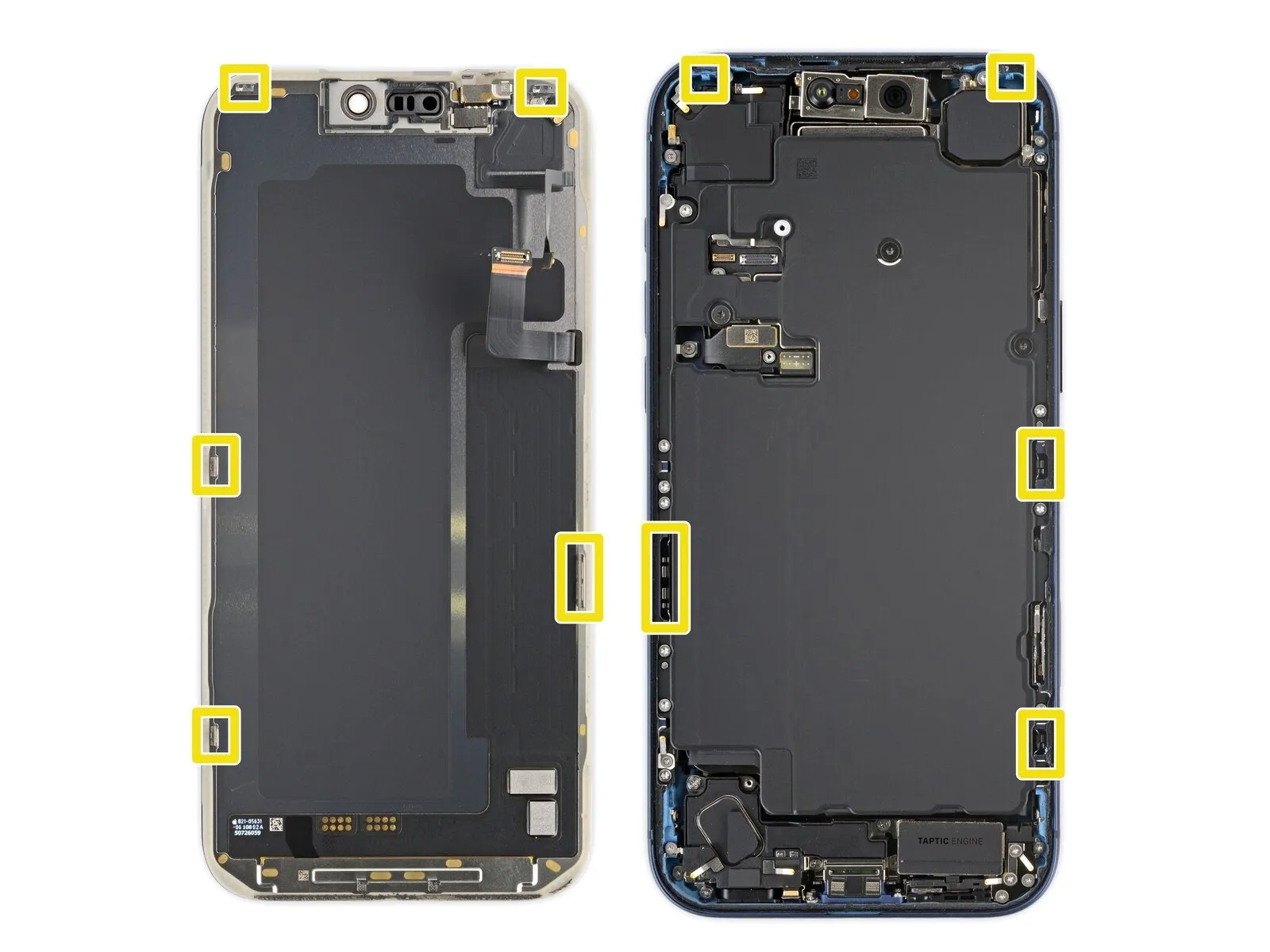
To prevent potential harm to internal parts, ensure the insertion depth of your prying tool remains limited to a maximum of 3 millimeters.Proximity to the volume and Action buttons places the screen and ambient light sensor cables in a vulnerable area.The phone's construction incorporates fragile spring contacts positioned along its edges, demanding careful handling.
- Thin, metallic clips secure the display assembly, engaging with matching receptacles situated on the device's frame.
- Exercise caution to prevent damage to the aforementioned components during separation.
- The screen's lower surface utilizes these clips to maintain its connection to the chassis.
Step 10 | Separate the bottom edge adhesive


Utilize a separation tool to gently release the adhesive bond by moving it along the lower perimeter of the device.
Maintain the tool's position beneath the lower-right corner to inhibit the adhesive from reforming a seal.
Step 11 | Remove the suction handle

- Detach the suction cup from the display by actuating the small protrusion located on its surface.
Step 12 | Heat the right edge


- To loosen the adhesive securing the display, apply warmth to the screen's right perimeter using a hair dryer or heat gun, ensuring the surface reaches a temperature just beyond comfortable touch.
Step 13 | Separate the right edge adhesive


- Position a second opening pick beneath the lower-right corner of the display assembly.
Advance the pick along the right side to detach the adhesive layer and disengage the two securing clips.Should separation prove difficult, a slight upward lift of the screen may be necessary to free the clips.
Apply force with the pick to elevate the screen if clip release is impeded.Maintain the pick's position beneath the upper-right corner to inhibit adhesive re-bonding.The adhesive's bonding properties can reform quickly, so proceed with care. - Separation of the adhesive and clips is achieved through controlled sliding motion of the opening pick.
Step 14 | Heat the top edge


- Employing a hair dryer or heat gun, apply warmth to the screen's upper boundary to achieve a temperature just beyond comfortable touch.The application of heat facilitates separation by softening adhesives securing the screen.Exercise caution during this process to prevent damage; excessive heat can degrade the screen's material.
Step 15 | Separate the top edge adhesive


- Position a third opening pick beneath the upper-right portion of the display assembly.
Carefully move the pick along the top perimeter, progressing just past the upper-left corner to detach the adhesive and disengage the two retaining clips.
Avoid advancing the pick further into the device, as this could potentially harm the ambient light sensor cable.The ambient light sensor cable is a delicate component.Maintain the pick's placement beneath the upper-left corner to inhibit the adhesive from reforming a seal.
This temporary support prevents the adhesive from re-bonding during subsequent steps.
Step 16 | Heat the left edge


Applying warmth with a hair dryer or heat gun to the left screen edge is necessary.The targeted area should be warmed to a temperature just beyond comfortable touch.This process facilitates screen separation by softening the adhesive.
Step 17 | Separate the left edge adhesive


- Position a fourth opening pick beneath the lower-left corner of the display assembly.
- Advance the pick along the left side to sever the adhesive bond and disengage the retaining clip, pausing its movement immediately prior to the volume up control.
- A slight upward lift of the screen may be necessary to free the clip; avoid further pick insertion to prevent potential damage to the display cable.
Step 18 | Prop up the screen
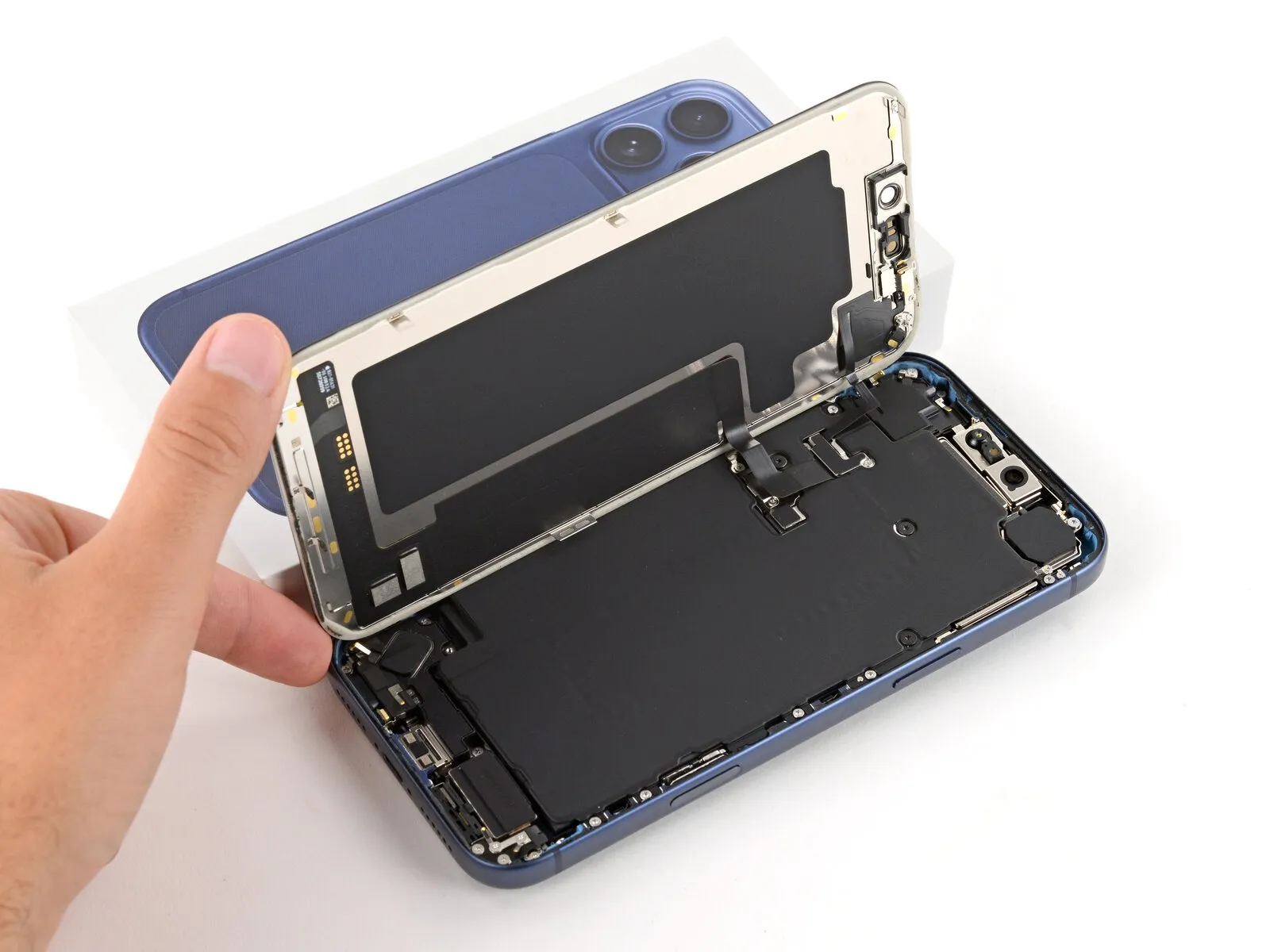
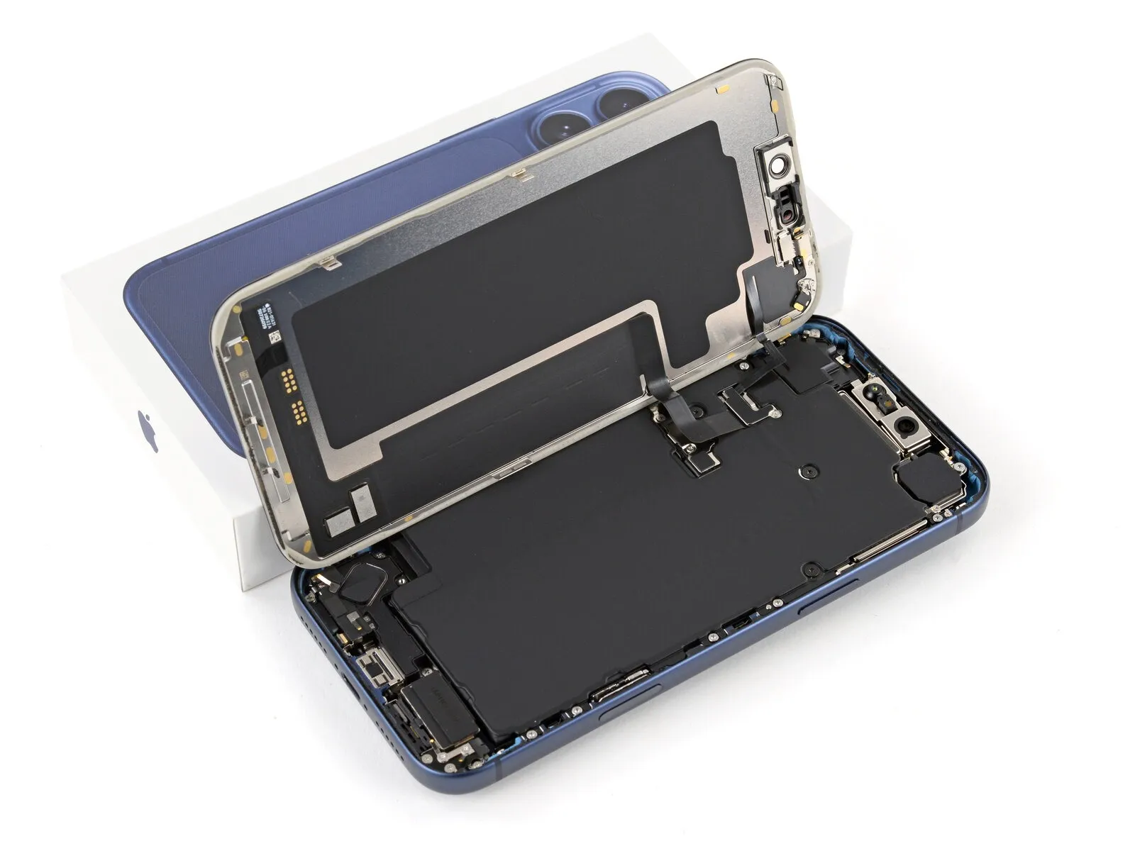
Ensure the display assembly is fully disengaged from the chassis; if resistance is encountered, re-examine the surrounding edges to release any lingering adhesive or securing fasteners.
Raise the display vertically and rotate it over the left side, supporting it with a stable object like a container or pile of literature to prevent cable tension; another option is to position the display horizontally across the left side.
Step 19 | Remove the cover screws
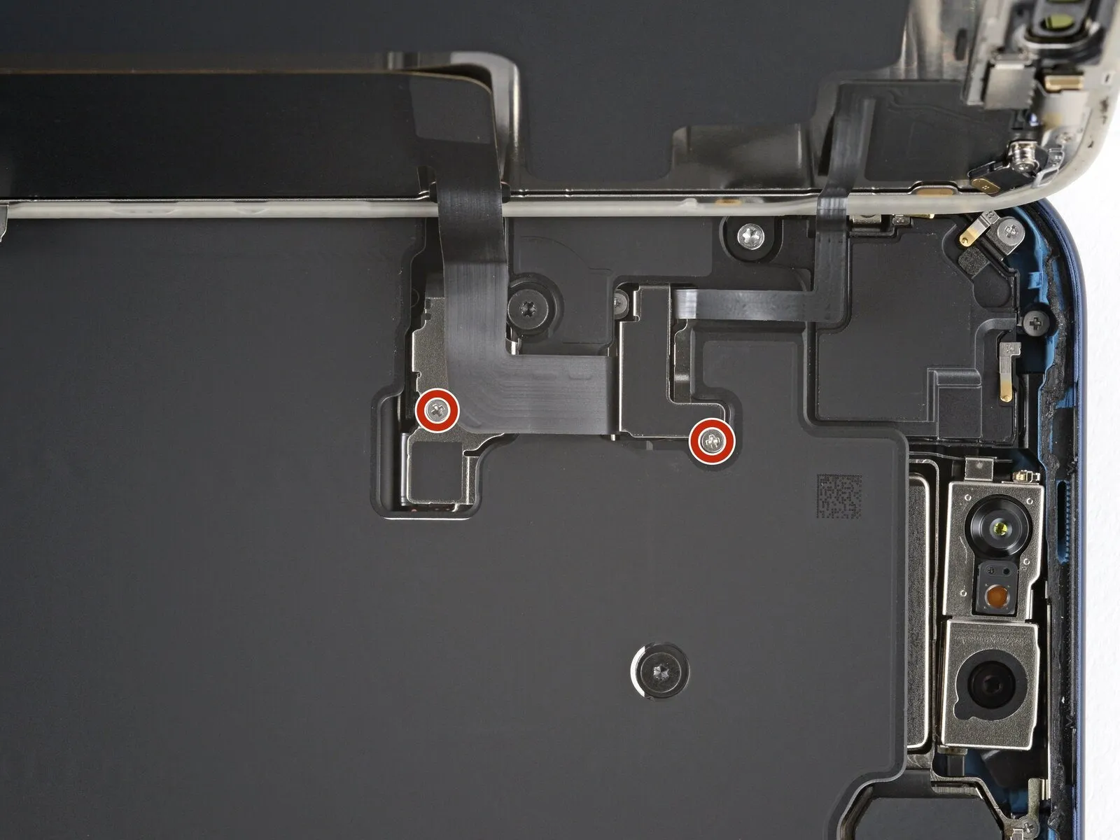
Carefully monitor the location of each screw during the repair process to ensure correct reinstallation.
Employ a JIS "00" screwdriver for the necessary screw removal operations.Two screws, each measuring 1.2 mm in length, fasten the battery and screen cable covers; these must be detached using the appropriate tool.iFixit-manufactured Phillips bits are suitable alternatives for JIS screws, though caution should be exercised when using other brands.The potential for screw damage exists if non-JIS Phillips screwdrivers are utilized.To prevent damage, it is crucial to select the correct screwdriver type when working with these fasteners.
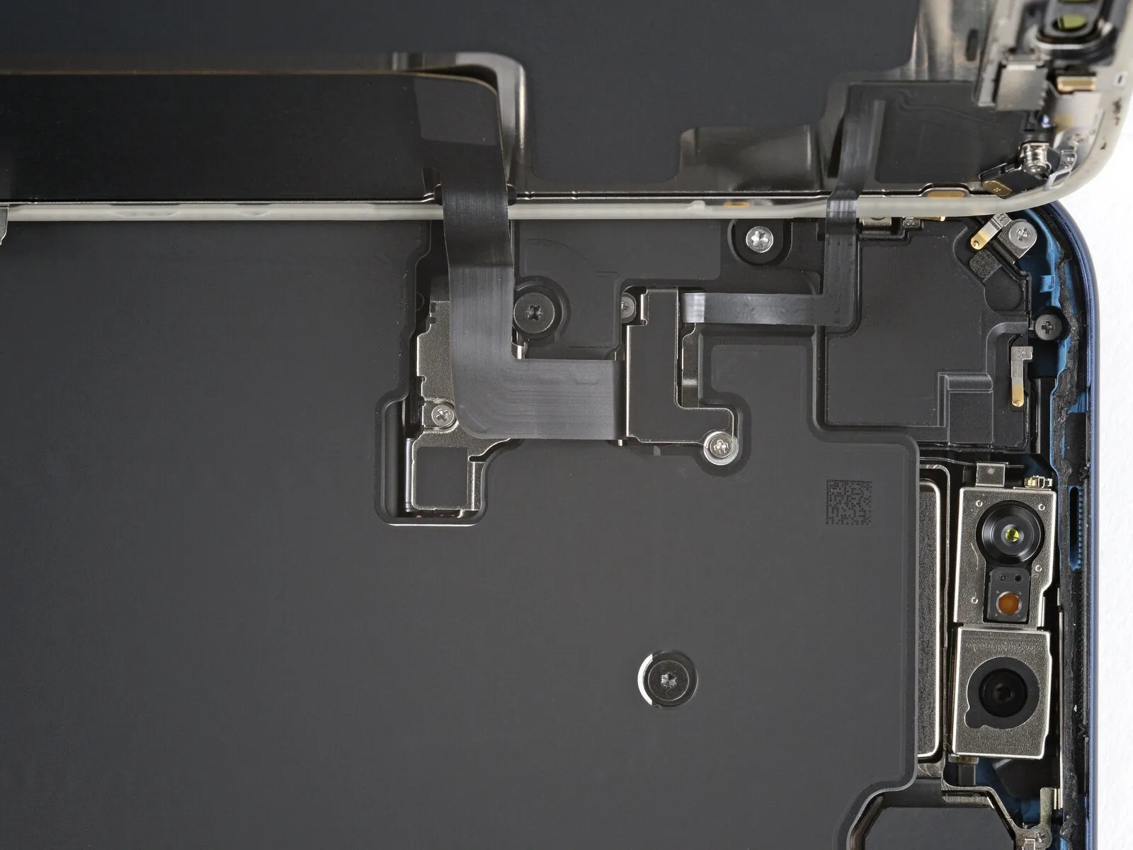
Step 20 | Remove the covers


Detach the pair of protective housings.
Step 21 | Disconnect the battery

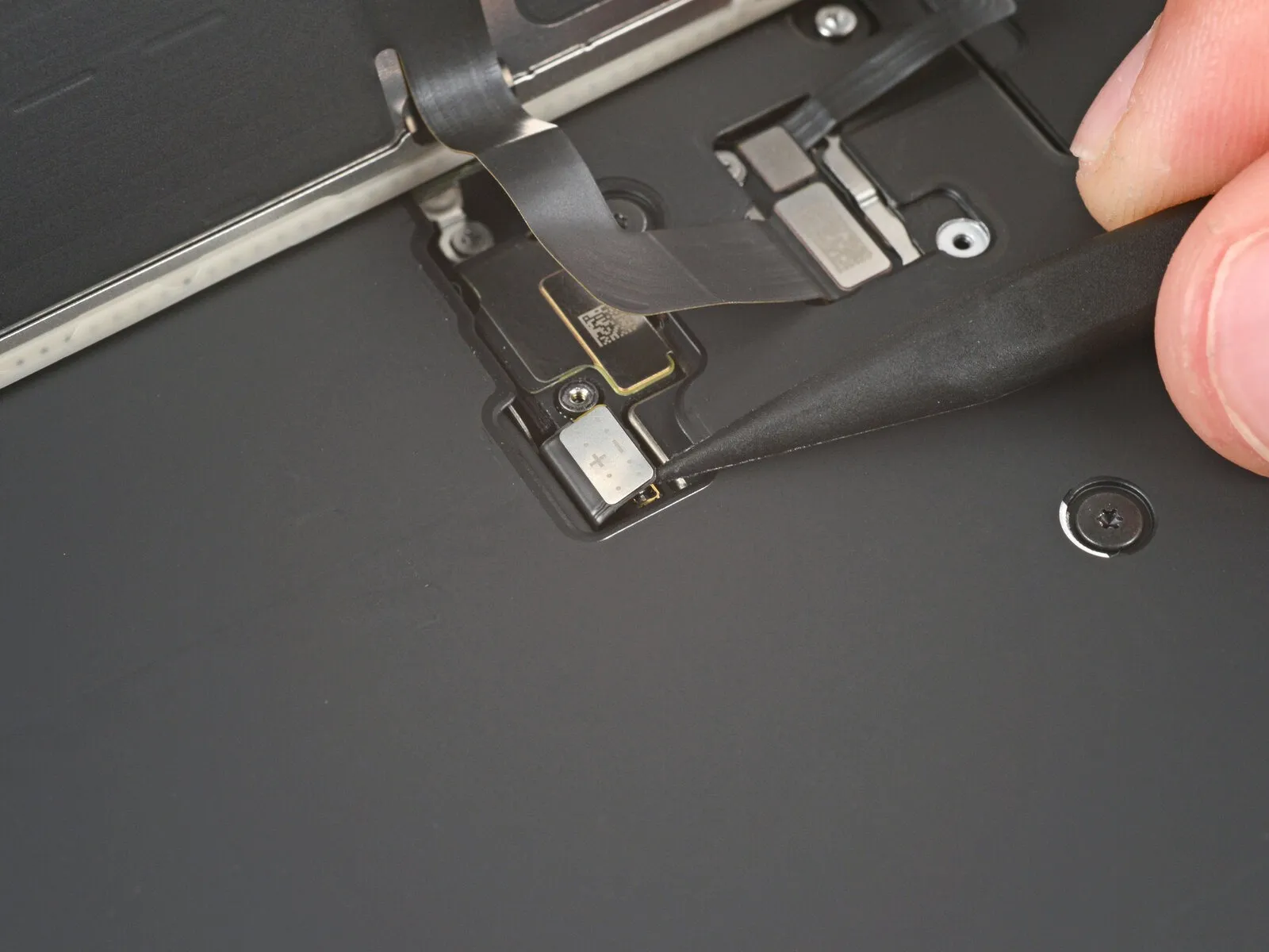
- Employ the tip of a spudger to carefully lift and detach the battery press connector.A spudger's pointed end facilitates the separation of the battery press connector from its socket.To release the battery press connector, apply gentle leverage with a spudger.
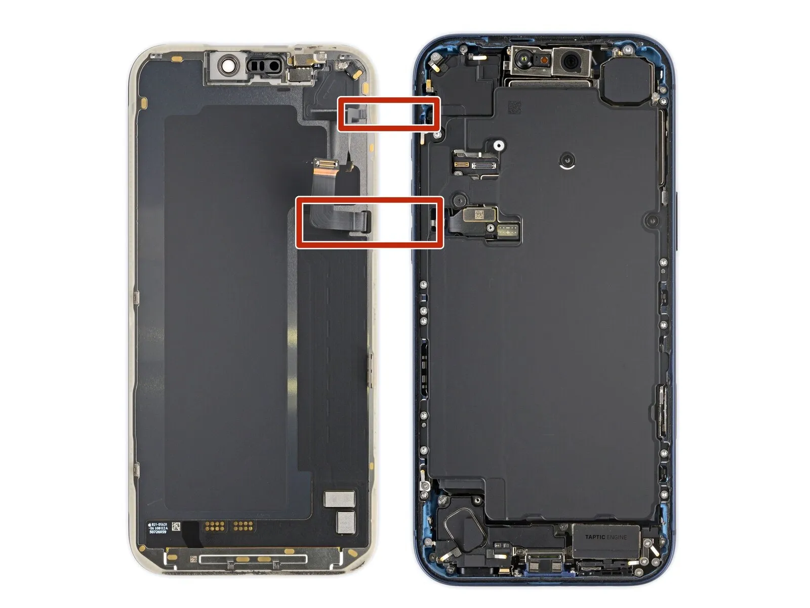
Step 22 | Disconnect the screen


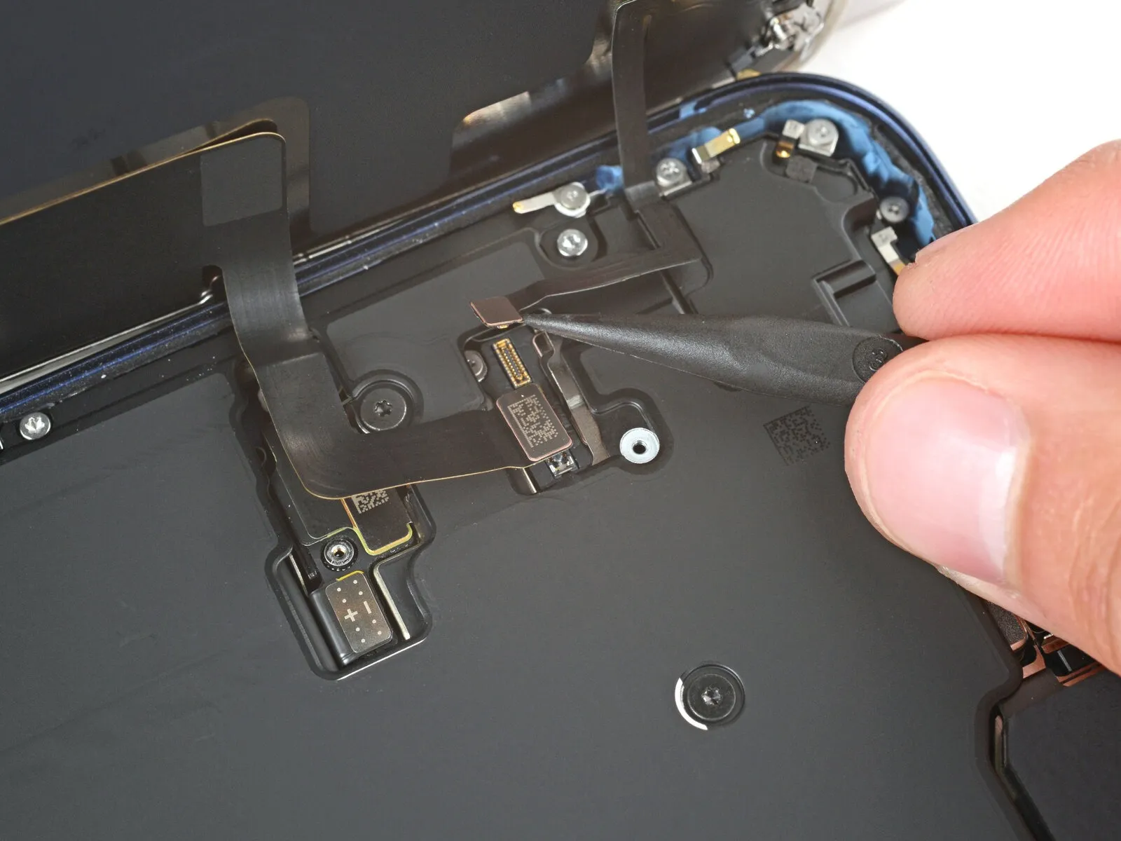
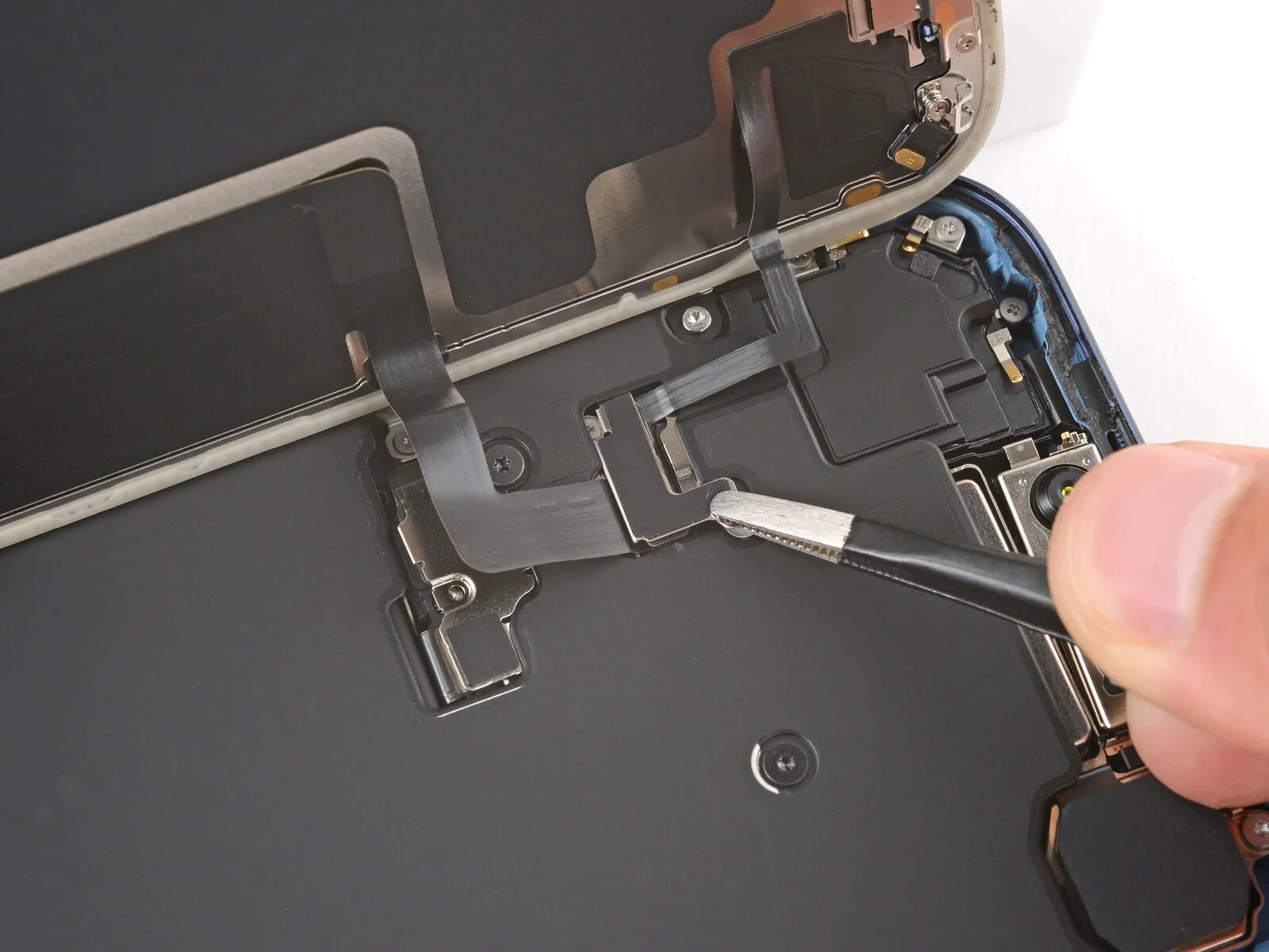
- Employing the pointed end of a prying tool or a spudger, carefully lift and separate the screen assembly and front sensors, ensuring disconnection by releasing their respective connectors.The connectors securing the screen and front sensors must be disengaged through careful leverage applied with a specialized tool, such as a prying pick or spudger.To release the screen and front sensors, utilize a prying tool's tip or a spudger's point to gently lift and detach the components while simultaneously disconnecting the associated press connectors.
Step 23 | Remove the screen
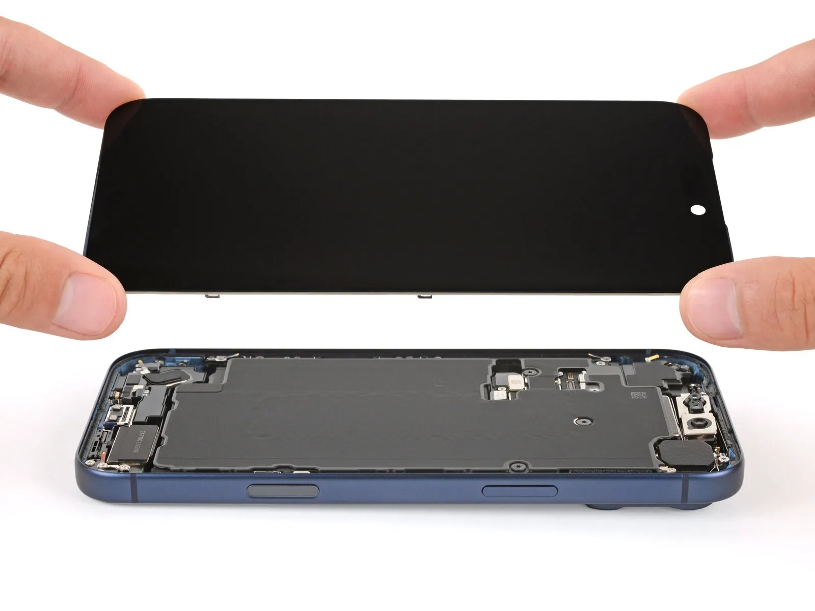
- Detach the display panel.
Step 24 | Remove the battery screws
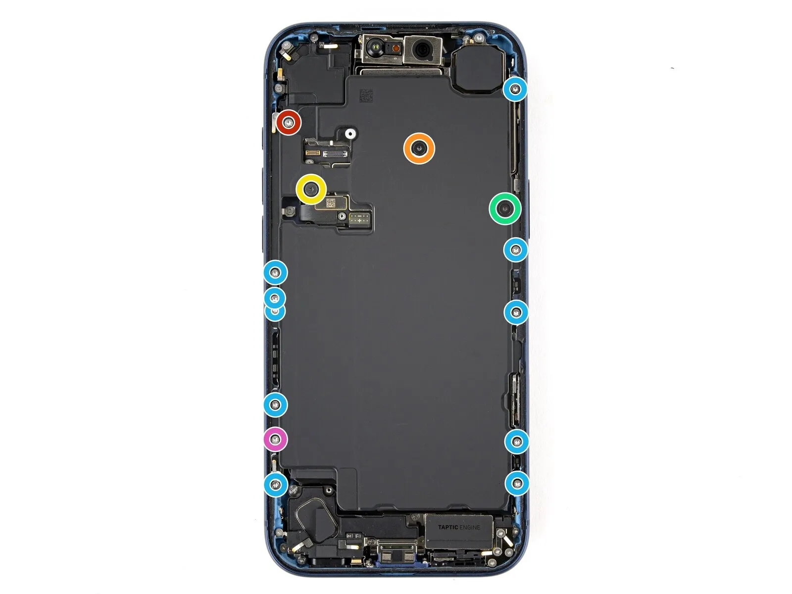
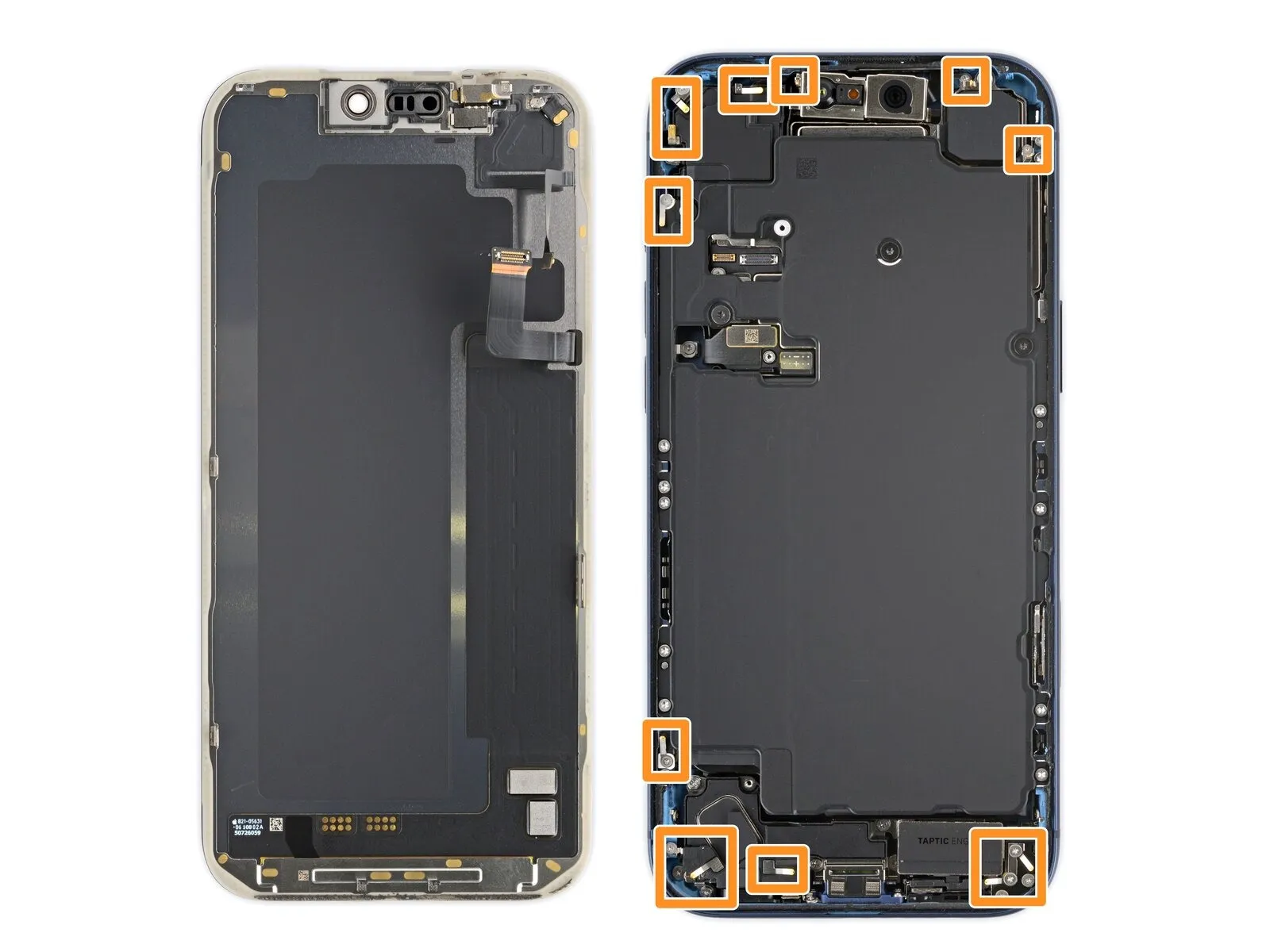
- Employ a Torx Plus 4IP screwdriver for the task of detaching the fasteners holding the battery compartment in place.A single screw, measuring 7.5 millimeters in length, is present.A solitary screw with a length of 5.9 millimeters is also included.
You will find one screw with a 3.5-millimeter length.A screw measuring 2.4 millimeters in length is also required.
Ten screws, each with a length of 3.7 millimeters, are utilized.An additional screw, also measuring 3.7 millimeters, is incorporated.
Certain iPhone versions, those incorporating a physical SIM card, lack this particular screw.The battery tray is affixed by multiple screws, necessitating careful removal.
To access the battery, the screws must be carefully unscrewed using the appropriate tool.The Torx Plus 4IP screwdriver is essential for preventing damage to the screw heads.
Ensure the correct screwdriver size is used to avoid stripping the screw heads.The screws securing the battery tray vary in length, so careful identification is needed.
Note the location of each screw as they are removed for correct reassembly.The presence or absence of the screw depends on the specific iPhone model's SIM configuration.
Proper handling of the screws is critical to avoid losing them or damaging the device.
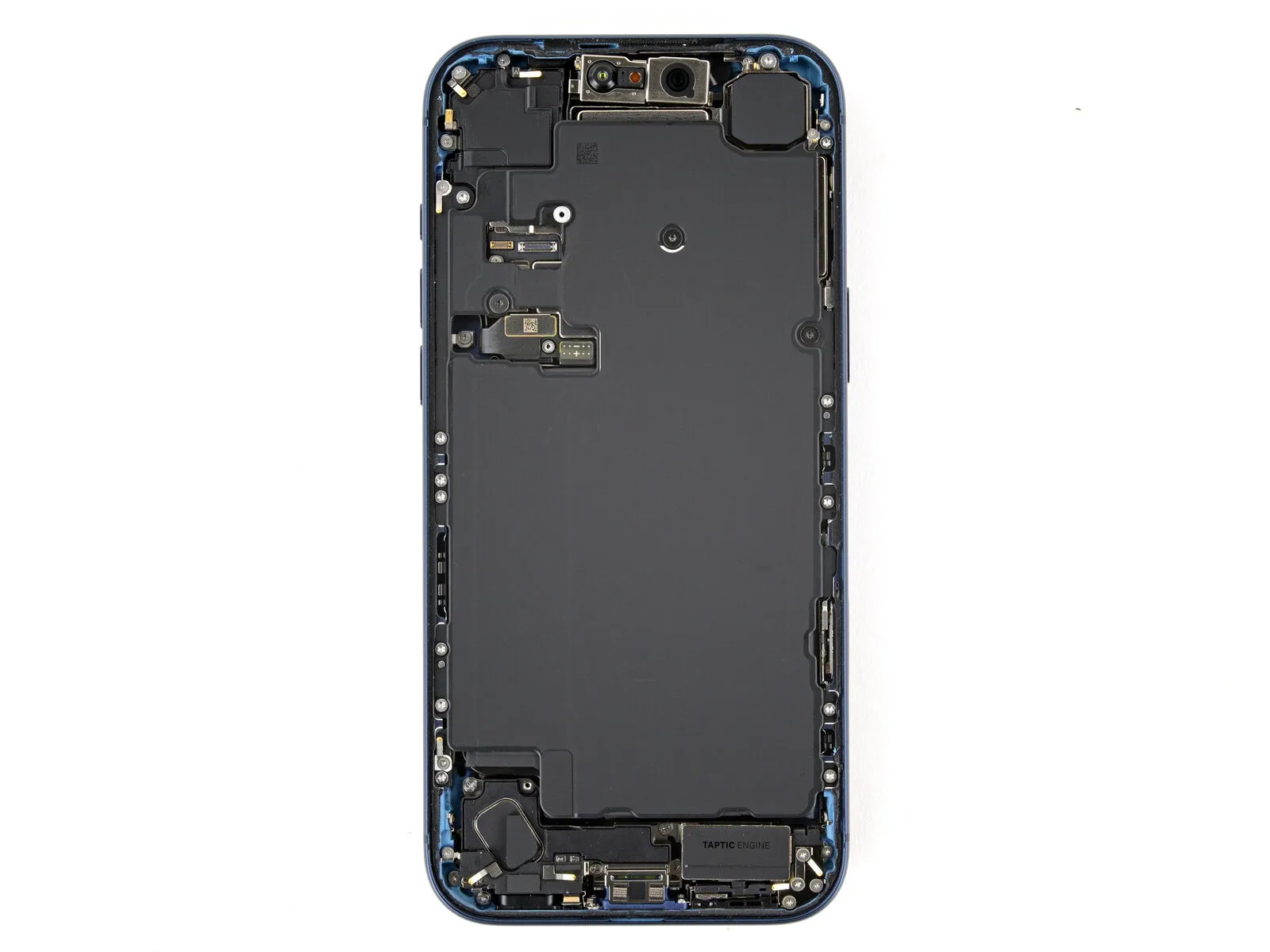
Step 25 | Remove the battery
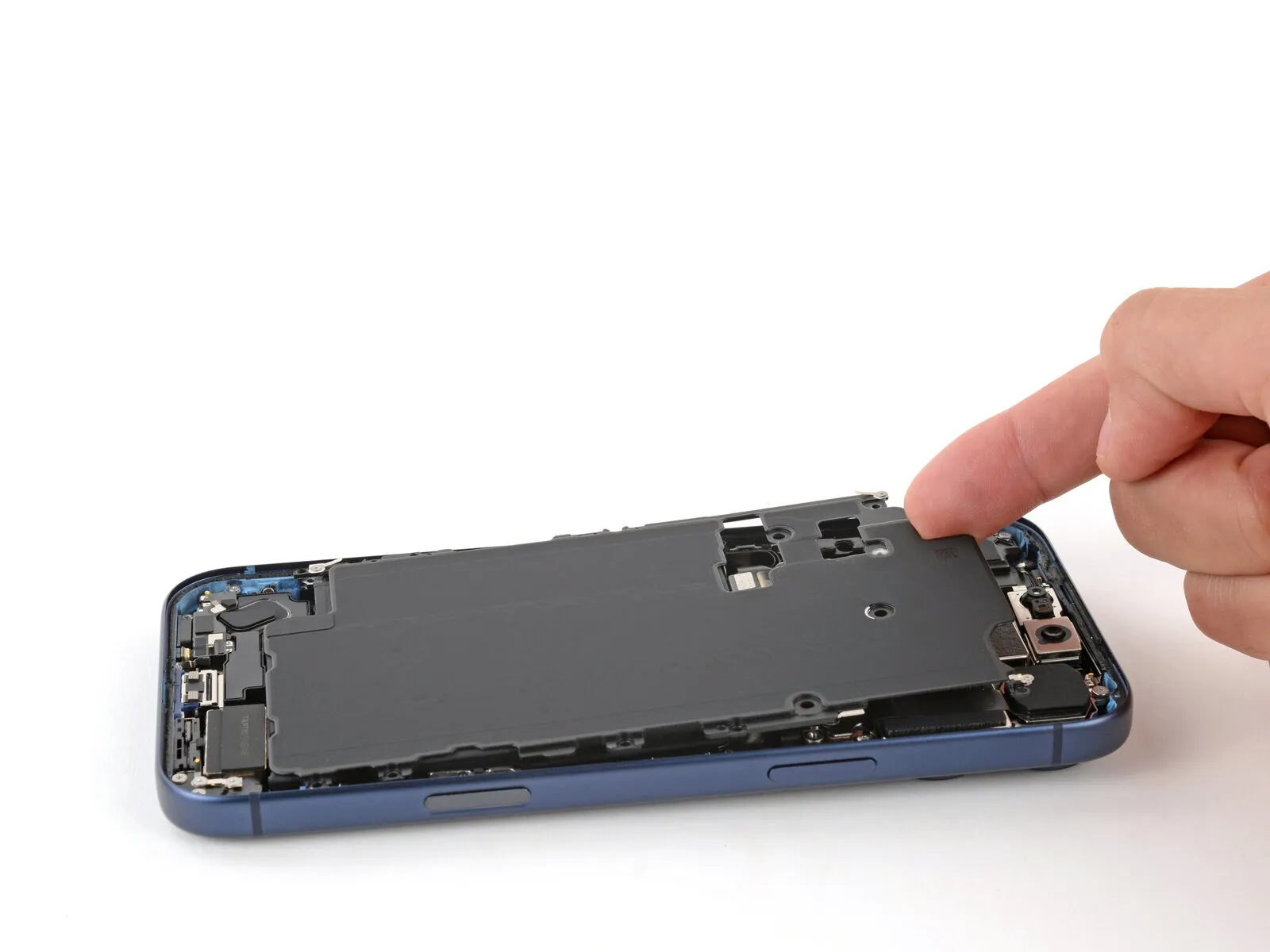
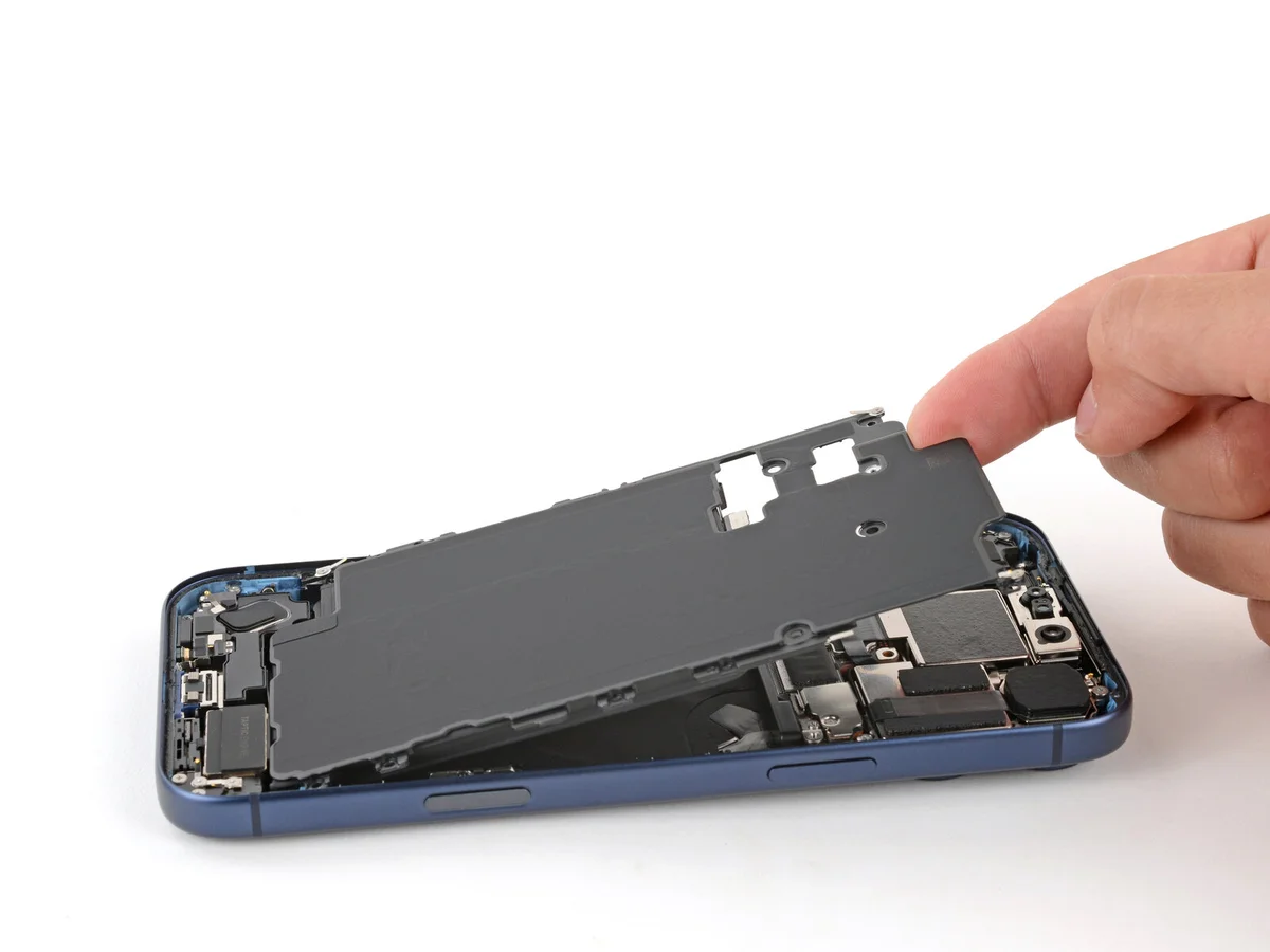

- Employ a fingertip to elevate the battery compartment's upper-left corner, subsequently detaching the cover.
Exercise caution to prevent any smearing of the front-facing camera lens.
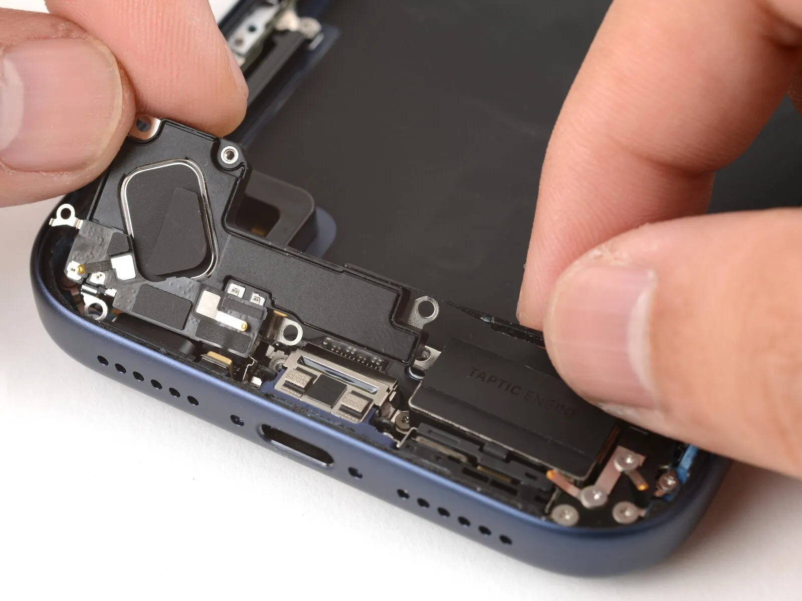
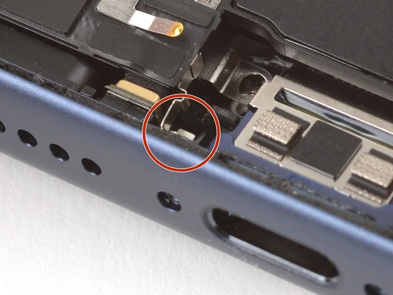
Step 26 | Separate the buffer strip
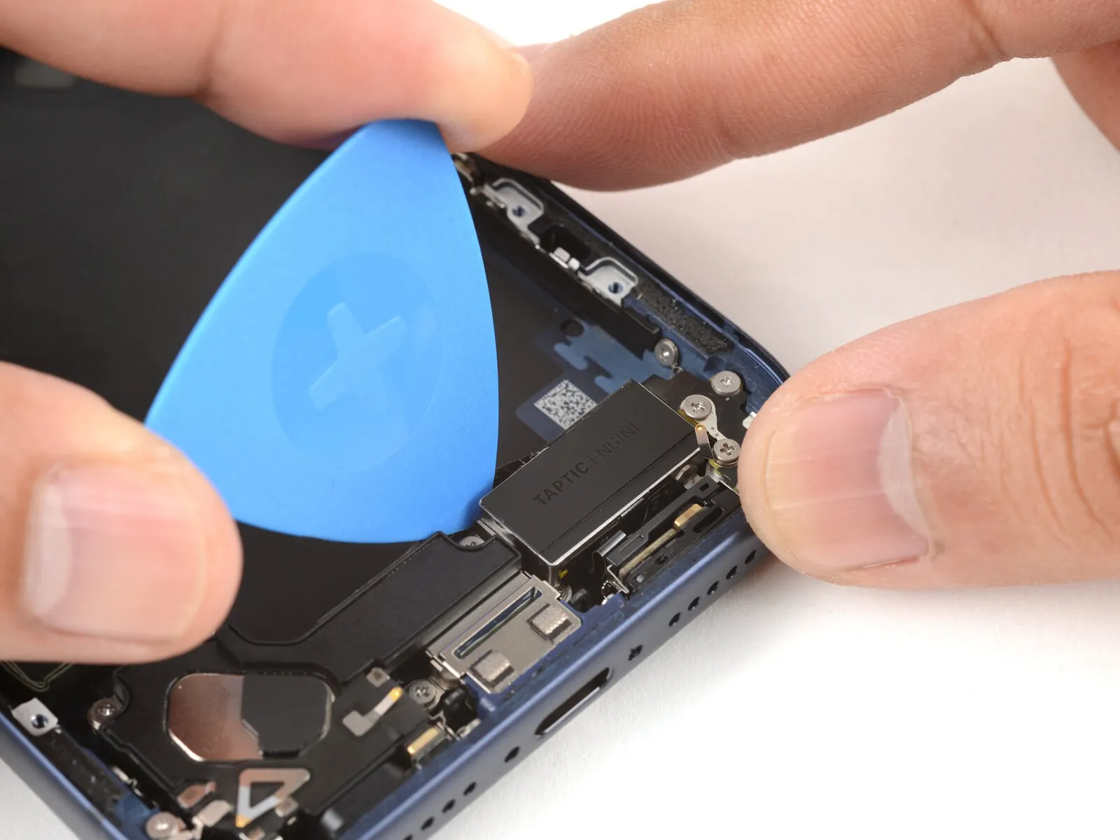

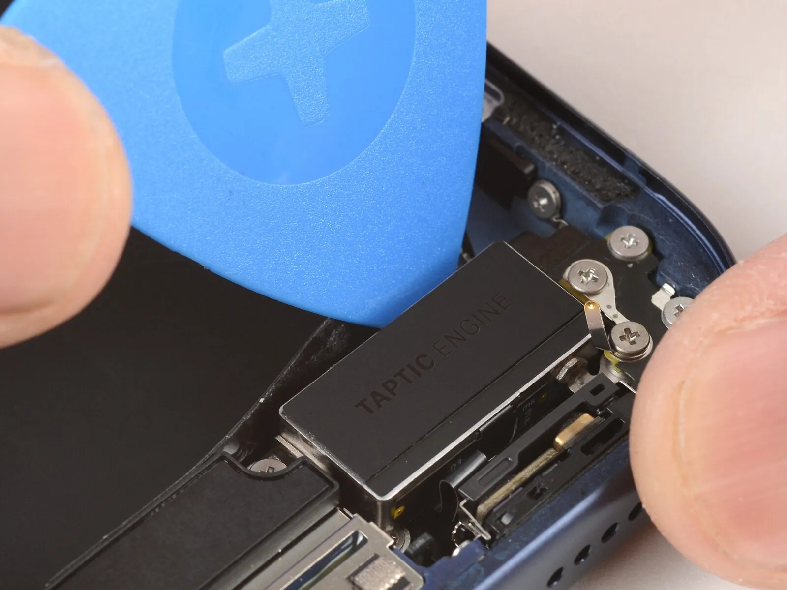
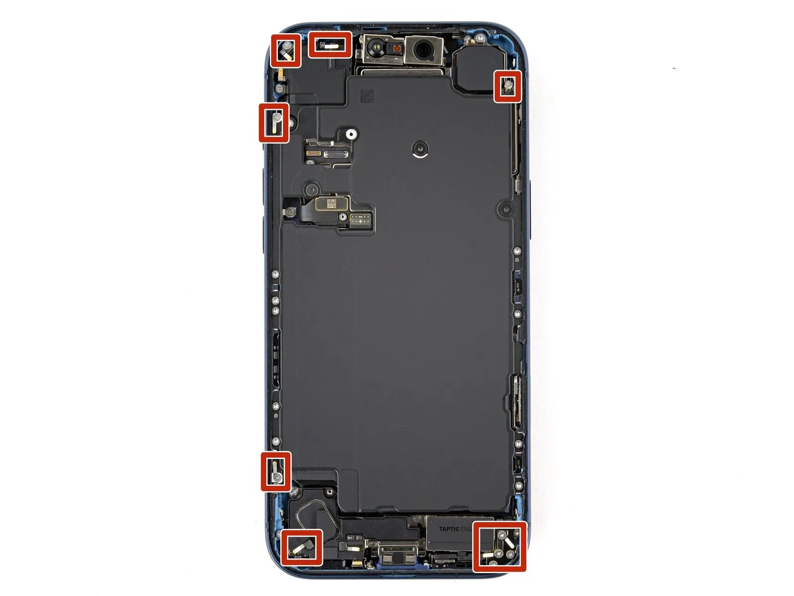
Step 27 | Remove the loudspeaker

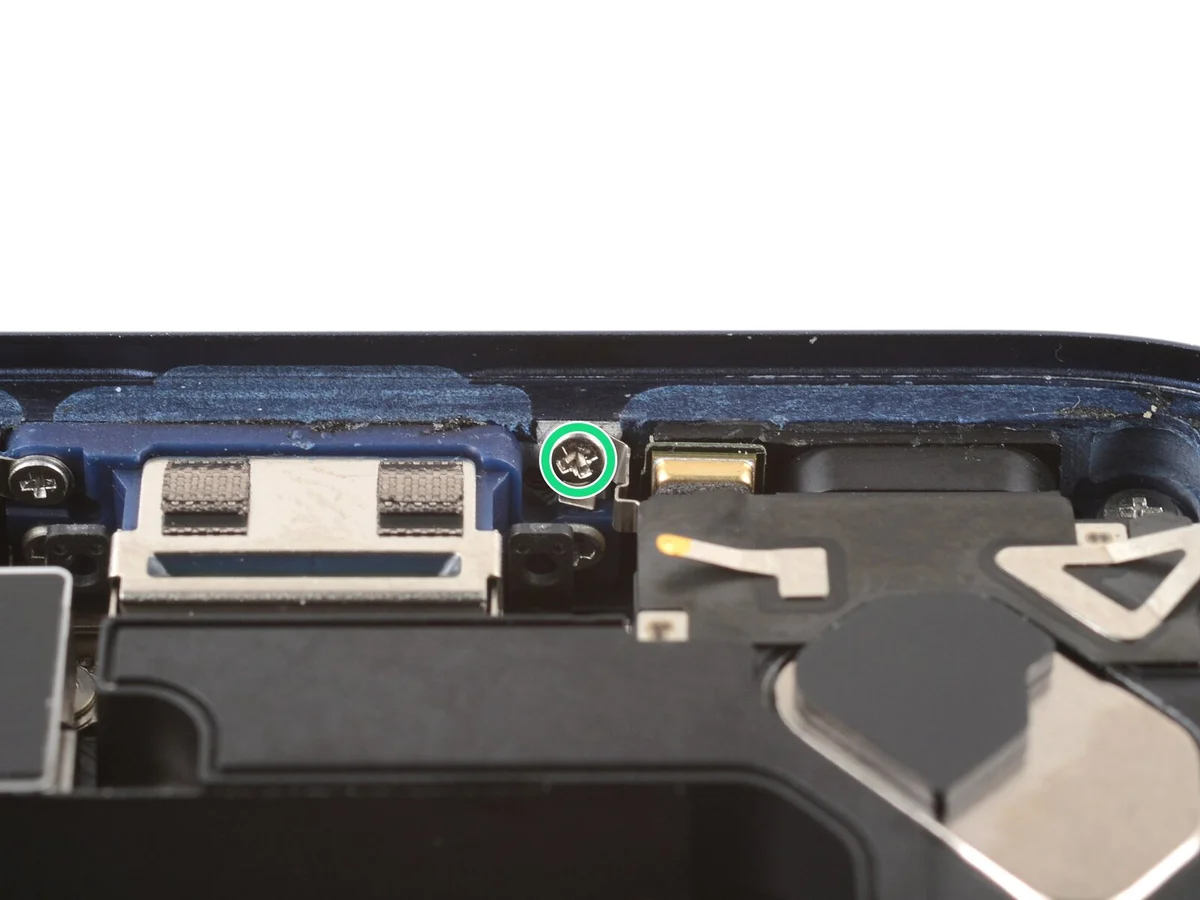
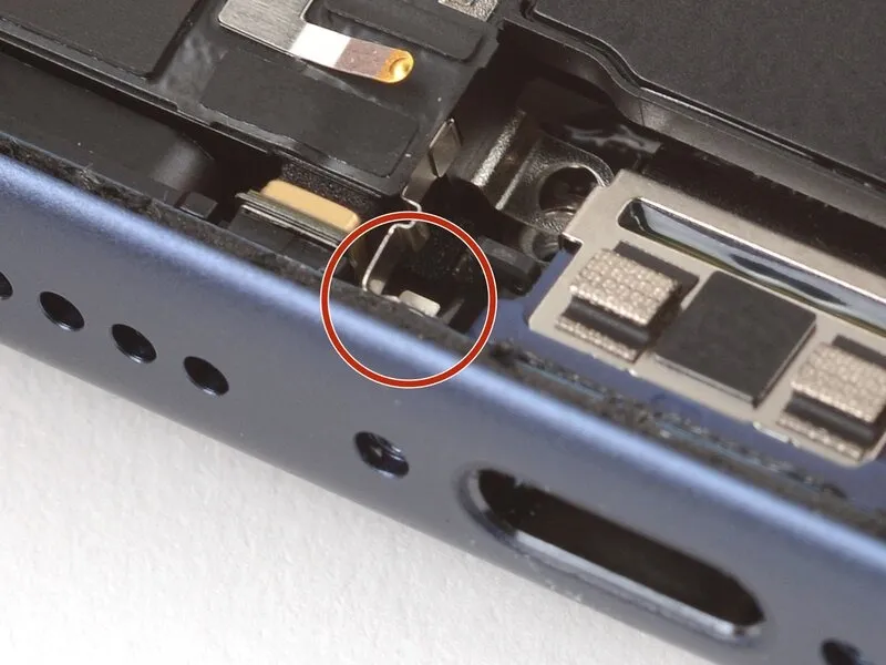
- A quantity of two screws, each measuring 2.7 millimeters in length, are present.Two screws, with a length of 2.0 millimeters, are also included.A single screw, possessing a length of 1.5 millimeters, is required.
- Another screw, also 1.5 millimeters in length, is necessary for the procedure.One 1.5-millimeter screw is affixed to the lower boundary of the component.The loudspeaker is fastened with a combination of screw lengths.
- Carefully unscrew the fasteners using the appropriate screwdriver.Ensure the JIS 00 screwdriver is properly seated on the screw heads to prevent damage.Note the different screw lengths for reassembly purposes.
- The 2.7 mm screws are likely securing a different part of the loudspeaker assembly.The 2.0 mm screws likely secure a different aspect of the loudspeaker.The 1.5 mm screws are used to attach the loudspeaker to the device's chassis.
Step 28

Step 29 | Disassembly complete

Step 30 | Install the loudspeaker
Step 31
- Employ a JIS 00 screwdriver for the installation of six screws securing the loudspeaker.
Secure two screws, each measuring 2.7 millimeters in length.
Utilize two screws, each with a length of 2.0 millimeters.
Fasten one screw, with a 1.5-millimeter length, to the assembly.
Attach a single 1.5-millimeter screw to the inferior border of the iPhone's structural frame.
Step 32 | Install the buffer strip

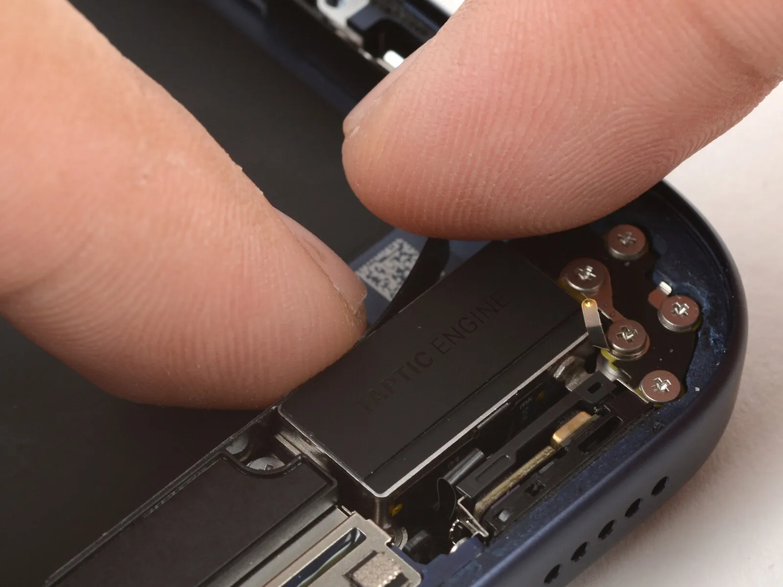
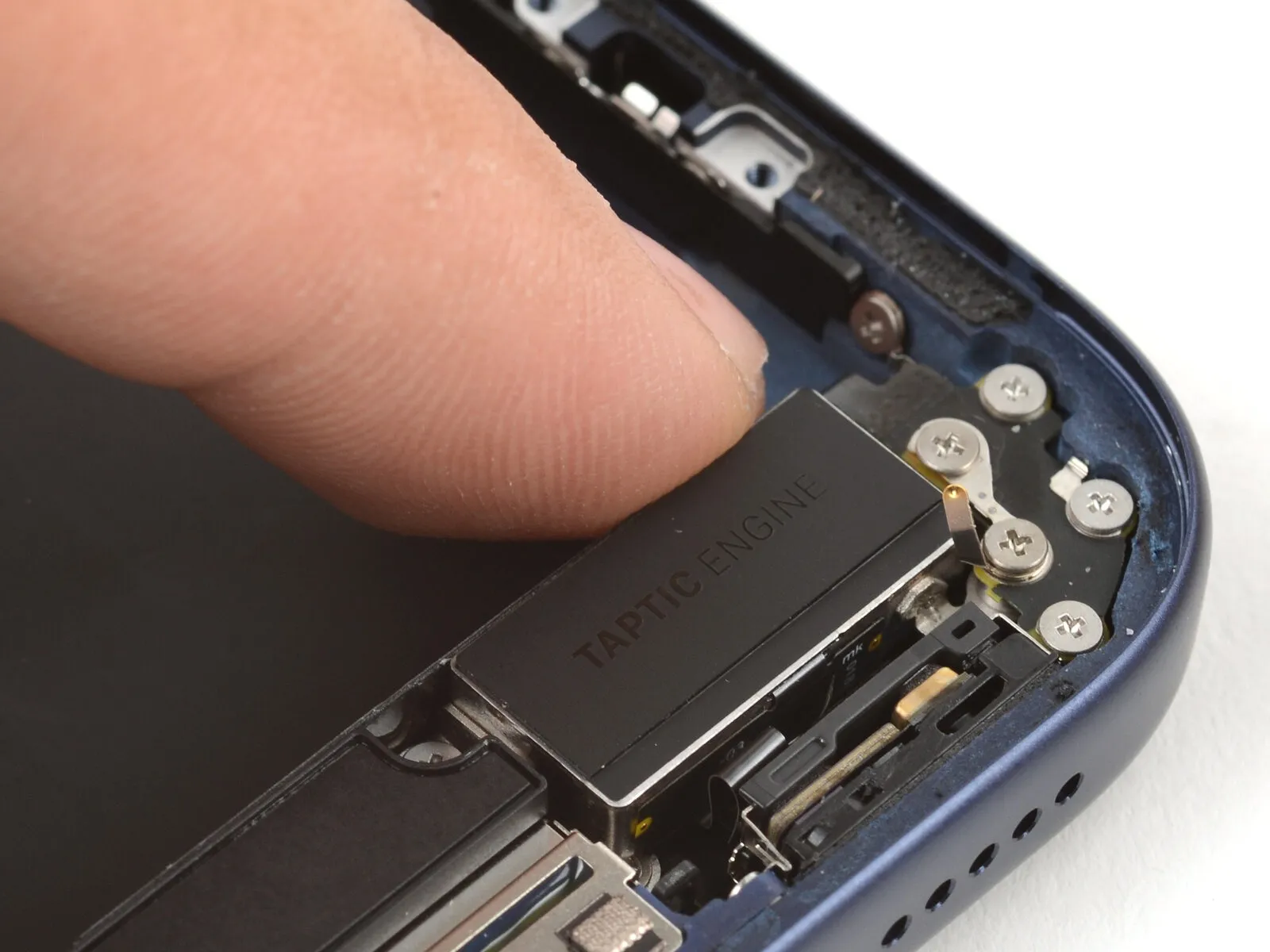
Reattach the buffer strip to the upper edge of the Taptic Engine, applying pressure with either your fingertips or a specialized spudger tool.
Step 33 | Install the battery
- Position the battery tray correctly within its designated area.
Exercise caution to prevent any wires from becoming pinched or obstructed by the tray's placement.
Step 34 | Install the battery tray screws
Employ a Torx Plus 4IP screwdriver for the battery tray screw installation process.A 7.5-millimeter-length screw is required for a specific location.A 5.9-millimeter-length screw is needed for another designated area.
- A 3.5-millimeter-length screw is necessary for a particular mounting point.A 2.4-millimeter-length screw is also required for a designated attachment.
Ten screws, each measuring 3.7 millimeters in length, secure another component.An additional 3.7-millimeter-length screw is used for a specific fastening.
Certain iPhone versions, those retaining a physical SIM card slot, lack this particular screw.The Torx Plus 4IP screwdriver is essential for proper screw engagement.
Secure the battery tray using the provided screws of varying lengths.Ensure accurate screw placement based on the specified lengths provided.
The 7.5 mm screw provides robust fastening for a critical area.The 5.9 mm screw contributes to the overall structural integrity.
The 3.5 mm screw is vital for a secure connection.The 2.4 mm screw serves a specific, smaller fastening requirement.
Models equipped with a physical SIM card will not include the mentioned screw.
Step 35 | Clean the frame


- Exercise caution while cleaning the frame, carefully avoiding damage to the delicate grounding clips; if displacement occurs, restore their original shape with your fingers or tweezers.
Employ tweezers or your fingertips to detach sizable adhesive fragments from the frame's edges.
Employ a spudger to eliminate remaining adhesive residue from the frame's surface.
Should the adhesive prove difficult to remove, apply warmth with a hairdryer or heat gun, and then attempt removal again.
Step 36

To dissolve the remaining adhesive, dispense a small quantity of isopropyl alcohol with a concentration exceeding 90%.
Employ a microfiber cloth or a similar lint-free material to carefully cleanse the frame's edges by wiping in a single direction.
Performing this process deliberately is crucial, as a pristine frame surface facilitates uniform adhesive application and strengthens the subsequent bond.
Step 37 | Clean the screen

To facilitate proper adhesion when reinstalling a display, utilize a small quantity of isopropyl alcohol with a 90% concentration.Employing a microfiber cloth or a lint-free alternative, carefully clean the display's edges with the alcohol.This preparatory cleaning step removes residue, ensuring optimal contact between the display and the fresh adhesive.
Step 38 | Orient the replacement adhesive


To ascertain the correct positioning of the adhesive layer, place it upon the frame's surface, ensuring that no protective liners are removed during this assessment.
- Employ the camera aperture and the indentations situated on the upper and lower borders as visual references to understand the adhesive's intended placement within the frame.
Step 39 | Apply the replacement adhesive

To reveal a portion of the adhesive, carefully lift the corner tab of the adhesive sheet's liner and remove it, exposing approximately one-third of the adhesive surface.
Due to its high tack, the revealed adhesive will adhere readily to surfaces; prevent unintended contact until it is positioned on the frame.
Should your adhesive contain several liners, remove only the uppermost liner to expose the side intended for attachment to the frame.
Step 40


After applying pressure to secure the adhesive, adjustments are impossible; any repositioning necessitates complete removal and replacement with fresh adhesive material.
Precisely match the visible perimeter of the adhesive strip to the matching boundary on the iPhone's structural frame, exercising caution.
Confirming proper alignment, delicately apply pressure to the visible adhesive strip, bonding it to the frame.
Step 41


- Proceed with removing the protective backing material from the adhesive strip while applying gentle pressure for secure placement.Ensure the adhesive material makes full contact with the surface by carefully pressing it down.Proper alignment of the adhesive is indicated when the borders seamlessly integrate with the device's frame.Should a slight misalignment occur, reposition the adhesive by carefully drawing the extended borders toward the frame.
- To correct any unwanted folds or wrinkles appearing in the adhesive, completely remove it and reapply a new strip.In the absence of replacement adhesive strips, the iPhone can be reassembled and used without them, although temporarily.Understand that the device's ability to repel water will be reduced until a replacement adhesive strip is installed.
- Continue the liner removal process, ensuring a smooth and even application of the adhesive.The adhesive's proper positioning is crucial for maintaining the device's integrity and functionality.Gentle pressure is recommended during the adhesion process to avoid air pockets or uneven surfaces.
- Misalignment can be corrected by carefully manipulating the longer edges of the adhesive strip.Creasing or wrinkling indicates a need to discard the current adhesive and begin the process anew.Using the iPhone without the adhesive strip is a temporary solution with potential drawbacks.The device's original water resistance capabilities will be diminished without the adhesive seal.Careful attention to alignment is essential for a successful adhesive application.
- A fresh adhesive strip is necessary to resolve issues with creasing or wrinkling.The adhesive strip should be pressed firmly to ensure a secure bond with the frame.Temporary use without the adhesive is possible, but compromises water protection.Realigning the adhesive is achieved by gently pulling the extended edges towards the frame's borders.Complete removal and replacement are the solutions for adhesive strips exhibiting significant creases.
Step 42

- Employ a spudger for applying pressure.The adhesive securing the device requires manipulation around its edges.Carefully maneuver around the delicate grounding clips to prevent damage.Should a grounding clip become displaced, restore its original position with fingertip pressure or tweezers.
- Avoid excessive force when repositioning grounding clips to prevent further issues.
Step 43


- Initiate the liner removal process by grasping the designated pull tab.Carefully detach the expansive front liner, revealing the adhesive surface.Locate the pull tab, which is typically situated within a corner of the liner.Remaining liners will persist along the device's edges; refrain from their removal at this stage.
- These perimeter liners serve a crucial purpose: preventing premature adhesion during reassembly.The adhesive layer remains protected by these liners to avoid unintended contact.Maintaining the liners' position ensures proper alignment and prevents the adhesive from bonding prematurely during the iPhone reassembly.
Step 44 | Connect the screen

Position the iPhone display assembly adjacent to the device's frame, ensuring sufficient cable slack for connection to the logic board.Arrange the replacement screen proximate to the chassis, allowing for adequate cable length to facilitate a secure connection with the main circuit board.
Step 45


Employ either a fingertip or the broad, planar edge of a spudger to establish a secure connection between the two screen connectors and the logic board.Avoid applying excessive pressure when aligning the connectors; a gentle touch is crucial for preventing damage.Should you encounter resistance during the connection process, carefully adjust the connector's position and attempt the alignment once more.
Successful engagement of the connectors relies on precise positioning, not brute force, to safeguard the delicate components.
Step 46 | Connect the battery


To establish a secure electrical connection between the battery connector and the logic board, apply pressure with either a fingertip or the broad, planar surface of a spudger.Ensure the battery connector is firmly seated on the logic board by utilizing the fingertip or the spudger's flat edge for application of force.A spudger's flat end, or a finger, can be employed to facilitate the attachment of the battery connector to the logic board via pressure.
Step 47 | Test your repair

Prior to final enclosure, it is advisable to verify the functionality of your iPhone repair.
- Initiate the iPhone's power sequence and confirm its operational status according to design specifications.
Should the device fail to energize, establish a connection to a power supply and attempt the startup procedure once more.
Step 48 | Install the battery connector cover


Carefully slide the upper border of the battery connector cover beneath the designated notch.
Verify that each of the two retaining tabs is securely positioned beneath the cover's edge.
Position the cover precisely using the screw aperture as a guide, then set it down onto the device.
Step 49

Employ a JIS 00 screwdriver for the installation process.The screw, measuring 1.2 mm in length, is required for this step.The battery connector cover's attachment necessitates the use of the screw.Secure the battery connector cover using the provided fastener.A JIS 00 screwdriver is essential for properly installing the 1.2 mm screw.
Step 50 | Install the screen connector cover


- Carefully slide the left side of the screen connector cover beneath the designated notch.
- Position the cover utilizing the screw aperture as a guide, then set it onto the device.
Step 51

Employ a JIS 00 screwdriver for the installation process.A 1.2 mm screw length is required for proper fastening.The screen connector cover necessitates secure attachment.Utilize the screwdriver to engage the screw head.This screw secures the cover, maintaining the screen connector's integrity.
Step 52 | Remove the final adhesive liners


- Maintain the screen's stability by grasping it securely with one hand.
- Employing either your fingertips or a spudger, carefully separate the perimeter liners to reveal the underlying adhesive.
- Prevent any contact with the newly exposed adhesive to avoid contamination.
- Thoroughly inspect the internal components, eliminating any detached liners to guarantee their complete absence.
Step 53 | Install the screen


- Position the display assembly onto the chassis, initiating the alignment process from the uppermost boundary.
Should you encounter opposition during installation, a perimeter clip might be deformed and experiencing compression from the frame’s structure.Carefully examine the area where resistance is detected, and delicately restore any clips that have been displaced from their intended shape.Verify that the display’s border isn’t exerting pressure on any flexible electrical connections.
Ensure that no wires are being compressed or damaged during the installation process.Confirm the absence of any obstructions preventing proper seating of the display.Apply even pressure across the display’s borders to achieve a completely level and uniform contact with the chassis.
Secure the display’s position by maintaining consistent pressure along all edges until a perfectly flat contact is established.
Step 54


- Apply consistent, substantial pressure encompassing the complete outer edge of the iPhone's housing.
Step 55 | Apply heat to the perimeter

Apply warmth around the display's edges using a hair dryer, heat gun, or iOpener until the surface reaches a temperature just above comfortable touch.
This thermal application reduces the adhesive's viscosity, facilitating a stronger subsequent bond.
Step 56 | Install the pentalobe screws
- Employ a P2 pentalobe screwdriver for the installation process.The required tool is a P2 pentalobe screwdriver.Two screws, each measuring 7.5 millimeters in length, are affixed.Secure the 7.5 mm screws using a P2 pentalobe screwdriver.Position the screws, which are 7.5 mm long, on both sides of the charging port, and tighten them with a P2 pentalobe screwdriver.