iPhone 17 Pro Max Top Speaker Replacement
This document details the procedure for removing and substituting the uppermost audio transducer, specifically the earpiece speaker, within an iPhone 17 Pro Max.The component being addressed is the top speaker, which is functionally referred to as the earpiece speaker.Auditory distortion, such as static or crackling noises emanating from the iPhone's top speaker, often indicates a need for replacement.
A degraded audio output from the top speaker is a common symptom requiring component intervention.The earpiece speaker's functionality is crucial for clear call audio and notification sounds.Replacement of the speaker resolves issues related to compromised sound quality during phone calls and media playback.Careful adherence to these instructions is essential to avoid further damage to the iPhone 17 Pro Max.Addressing the speaker issue restores optimal audio performance and resolves the described sound anomalies.
Step 1 | Safety precautions


To ensure optimal results, allow your iPhone's battery to discharge to a level below 25 percent prior to commencing the repair procedure.A fully charged lithium-ion battery presents a fire hazard if compromised during the repair process.
- Disconnect all connecting cables from the device before proceeding with the repair.
- Initiate a power-down sequence by simultaneously pressing the power button and either volume button, subsequently sliding to turn off the device.
Step 2 | Cracked glass preparation


Important safety notice: Fragments of broken glass present a hazard during the repair process and may inflict harm.Should your device's display exhibit cracks, proceed with the following procedure with heightened care.
- Secure the fractured glass surface by applying adhesive packing tape, ensuring complete coverage to prevent glass dispersal and facilitate suction cup adhesion.
- Affix one strip of tape—without overlapping—to the lower edge, ensuring sufficient dimensions to accommodate the suction cup.
- Limit tape application exclusively to the glass portion, avoiding contact with the phone's structural frame.
Step 3 | Remove the pentalobe screws


Employ a P2 pentalobe screwdriver to detach the two screws, each measuring 7.5 mm in length, located on both sides of the charging port.The two screws securing the device near the charging port require removal using a specialized P2 pentalobe screwdriver.To access the charging port area, utilize a P2 pentalobe screwdriver and unscrew the pair of fasteners, each with a 7.5 mm length, situated on the port's lateral edges.
Step 4 | Mark your opening picks


Pay close attention to the following safety instruction.Excessive insertion of the opening pick poses a risk of device damage.
- Accurately determine a 3-millimeter distance from the pick's tip and clearly indicate this point with a permanent marker.
- As an alternative method, secure a coin to the pick's tip using tape, positioning it 3 millimeters from the end.
Step 5 | Heat the bottom edge

A critical warning: Incorrect application of heat using a heat gun carries a significant risk of damaging the display panel and/or the battery; adhere meticulously to the detailed instructions provided at the referenced link.To facilitate separation, apply warmth to the lower screen perimeter utilizing either a hair dryer or a heat gun, ensuring the surface reaches a temperature just beyond comfortable touch.
- Failure to observe the prescribed heat application techniques with a heat gun may result in irreparable harm to the display and/or battery; consult the linked instructions for precise guidance.
Step 6 | Apply a suction handle


To facilitate separation, position a suction handle against the lower screen border, ensuring it's situated as near the edge as feasible.
Step 7 | Screen bezel information


Confirm the proper placement of your prying tool before proceeding to the subsequent repair stage.
- A plastic bezel, situated beneath the screen and resting against the device's frame, requires careful tool insertion; ensure the prying tool is fully positioned beneath this bezel.
- Avoid inserting the prying tool into the visible joint located between the plastic bezel and the display panel, as this action could inadvertently detach them, thereby increasing the repair's complexity.
Step 8 | Insert an opening pick


Apply consistent, substantial upward pressure to the suction cup's handle to separate the display screen from its surrounding frame, creating a visible space.
Overcoming the adhesive bond might require considerable effort; should initial attempts prove unsuccessful, reapplying heat to the screen's surface and retrying the separation process is recommended.
Carefully position the pointed end of a specialized opening tool within the newly formed separation to facilitate further screen detachment.
Step 9 | Screen information
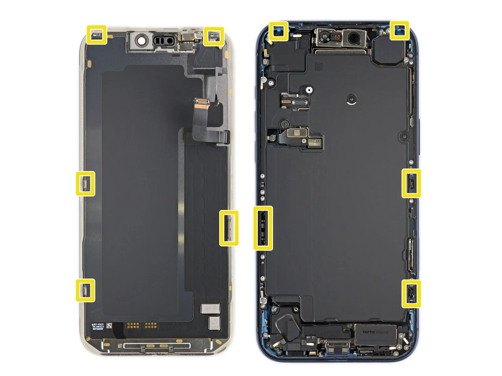
To prevent component damage, ensure the insertion depth of your prying tool remains less than 3 millimeters.Proximity to the volume and Action buttons places the screen and ambient light sensor cables at risk of harm.Care must be exercised due to the presence of fragile spring contacts positioned along the device's edges.
- The screen's lower surface incorporates thin metal clips designed to engage with matching slots within the phone's frame.
- These clips provide structural support and require careful handling to avoid deformation or breakage.
- Maintaining a shallow insertion depth is crucial to prevent unintended contact with these sensitive internal elements.
Step 10 | Separate the bottom edge adhesive


Utilize a separation tool to disengage the adhesive bond by moving it along the device's lower perimeter.
Maintain the tool's position beneath the lower-right corner to inhibit the adhesive from reforming a seal.
Step 11 | Remove the suction handle

- Detach the suction cup from the display by actuating the small protrusion located on its surface.
Step 12 | Heat the right edge


- To loosen the adhesive securing the display, apply warmth to the screen's right border with a hair dryer or heat gun, ensuring the surface reaches a temperature just beyond comfortable touch.
Step 13 | Separate the right edge adhesive


- Position a second opening pick beneath the lower-right corner of the display assembly.
Advance the pick along the right side, lifting it to sever the adhesive bond and disengage the two securing clips.Should resistance be encountered, a slight upward force may be necessary to free the clips.
Employ a prying action if needed to overcome adhesive adhesion and release the retaining clips.Maintain the initial pick's position beneath the upper-right corner to inhibit adhesive re-adhesion.The adhesive layer is designed to create a strong bond; therefore, deliberate and controlled separation is essential. - Separating the adhesive requires careful manipulation to avoid damaging the display or chassis.
Step 14 | Heat the top edge


- Employing a hair dryer or heat gun, apply warmth to the screen's upper border to achieve a temperature just beyond comfortable touch.The application of heat facilitates separation by softening adhesives along the screen's perimeter.Maintain a cautious approach, ensuring the temperature does not exceed a level that could damage the display or surrounding components.
Step 15 | Separate the top edge adhesive


- Position a third opening pick beneath the screen's upper-right quadrant.
Moving the pick along the top perimeter, gently maneuver it past the upper-left corner to detach the adhesive and disengage the two retaining clips.
Avoid advancing the pick further, as this could potentially harm the ambient light sensor cable.Maintain the pick's position beneath the upper-left corner to inhibit the adhesive from reforming a seal.The adhesive separation should be achieved with minimal movement to prevent component damage.
This technique ensures a controlled release, minimizing the risk of injury to delicate internal components.
Step 16 | Heat the left edge


Applying warmth with a hair dryer or heat gun to the screen's left border is necessary, continuing until the surface reaches a temperature just beyond comfortable touch.The purpose of this heating process is to loosen the adhesive securing the screen.Exercise caution during this step; excessive heat could damage the display or underlying components.
Step 17 | Separate the left edge adhesive


- Position a fourth opening pick beneath the lower-left corner of the display assembly.
- Advance the pick along the left side to sever the adhesive bond and disengage the retaining clip, pausing its movement immediately prior to the volume up control.
- A slight upward lift of the display panel might be necessary to free the clip; avoid further pick manipulation beyond this point to prevent potential damage to the display cable.
Step 18 | Prop up the screen
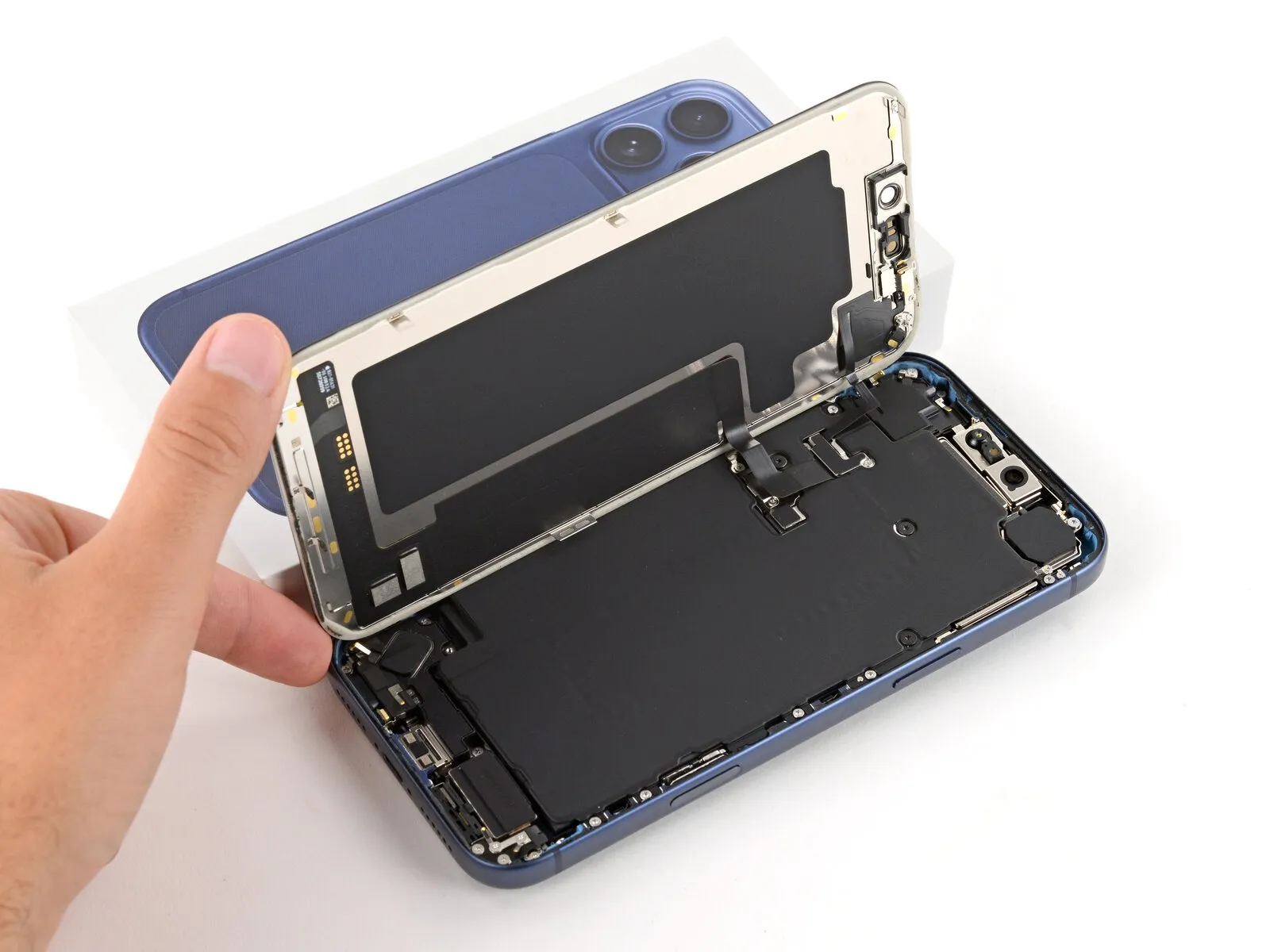
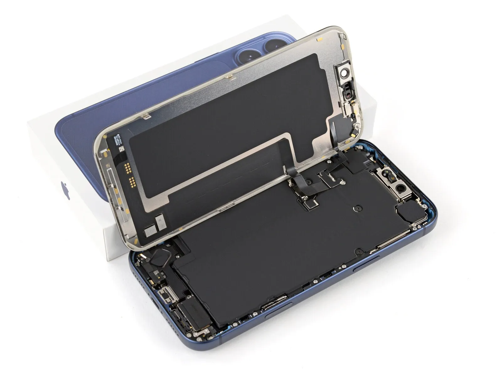
Ensure the display assembly is fully disengaged from its surrounding structure; if resistance is encountered, re-examine the edges to release any lingering adhesive or securing fasteners.
Elevate the display vertically and rotate it across the left side, supporting it with a stable object like a container or pile of literature to prevent cable tension; as an alternative, the display can be placed horizontally across the left surface.
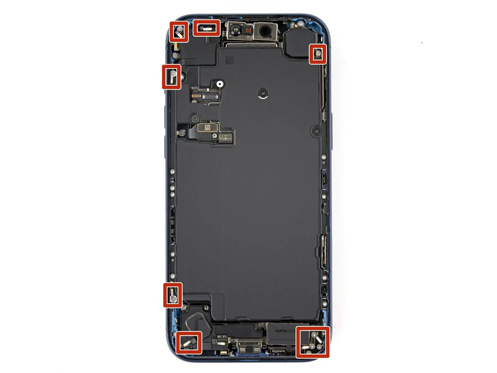
Step 19 | Remove the cover screws
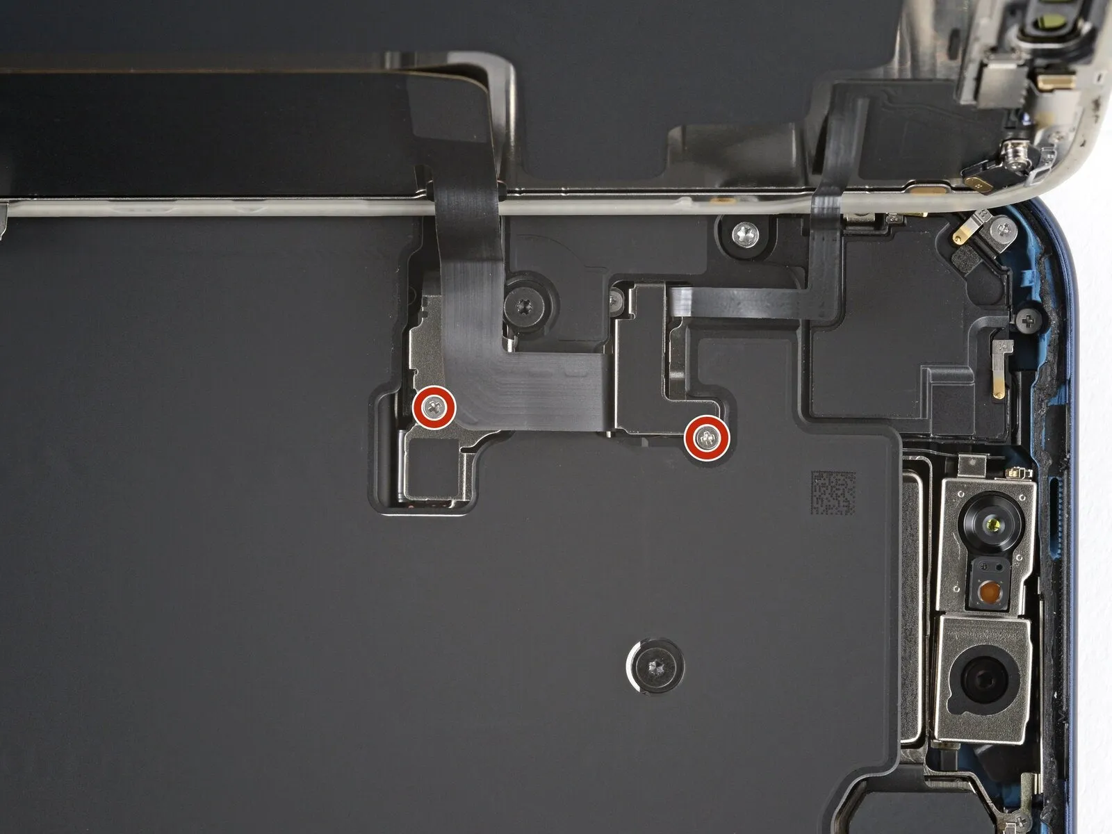
Meticulously organize all screws during the repair process, ensuring each is reinstalled in its original location.
Employ a JIS 00 screwdriver to detach the two 1.2 mm-long screws that fasten the battery and screen cable covers, with one screw per cover; alternative Phillips bits may damage the screws.
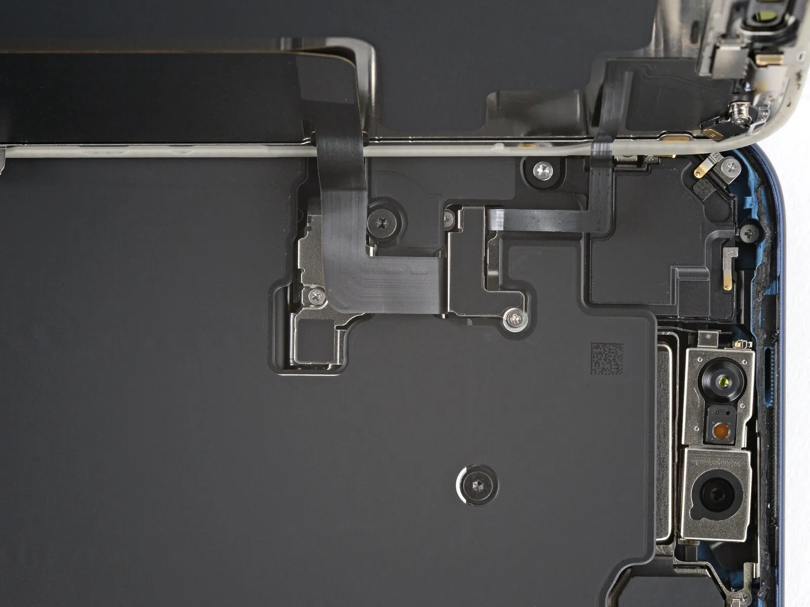
Step 20 | Remove the covers


Detach the pair of protective housings.
Step 21 | Disconnect the battery

- Employ the tip of a spudger to carefully lift and detach the battery press connector.A spudger's pointed end facilitates the separation of the battery press connector from its socket.To release the battery press connector, apply focused pressure with a spudger's tip to achieve disconnection.
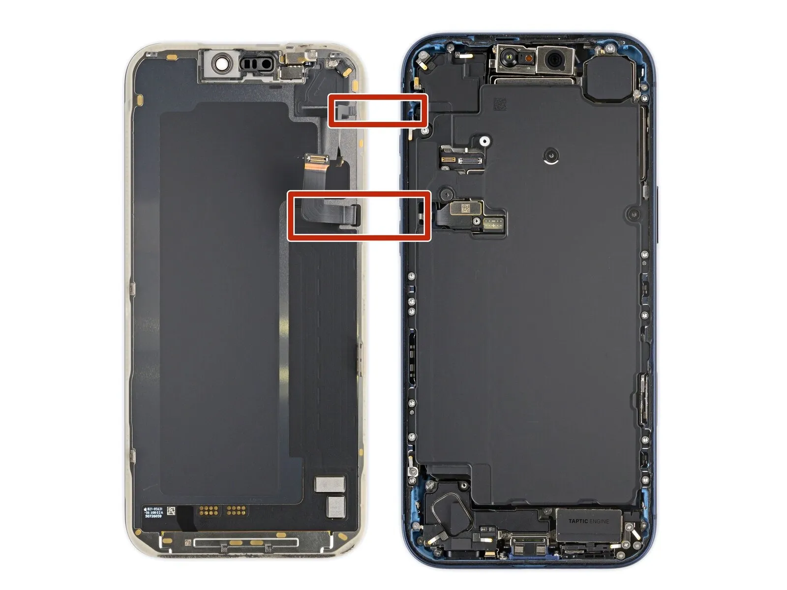
Step 22 | Disconnect the screen


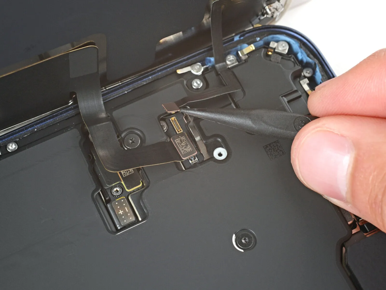
- Employing the pointed end of a prying tool or a spudger, carefully lift and separate the screen assembly and front sensors, ensuring disconnection by releasing their respective connectors.A specialized opening pick or a spudger's tip can be utilized to elevate and detach the screen and front sensors, necessitating connector separation during the process.To release the screen and front sensors, utilize the pointed end of a prying tool or a spudger, subsequently disconnecting the connectors that secure them.
Step 23 | Remove the screen
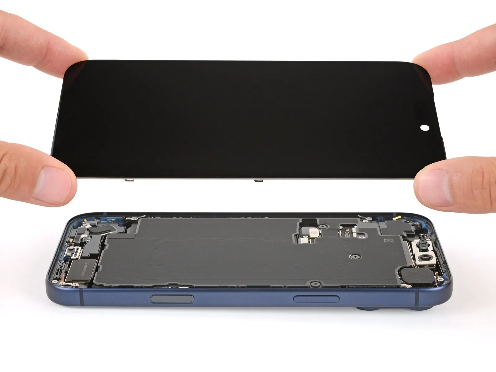
- Detach the display panel.The screen component must be extracted.Carefully disassemble the display assembly.
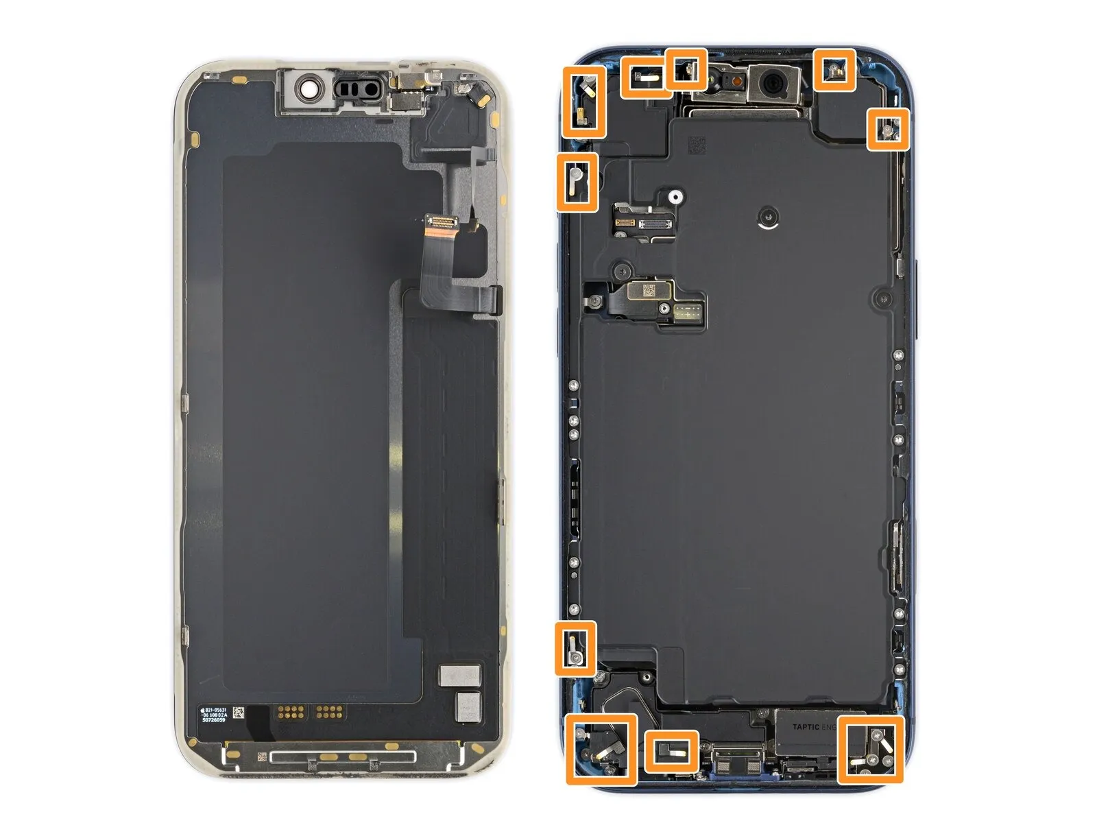
Step 24 | Remove the battery screws
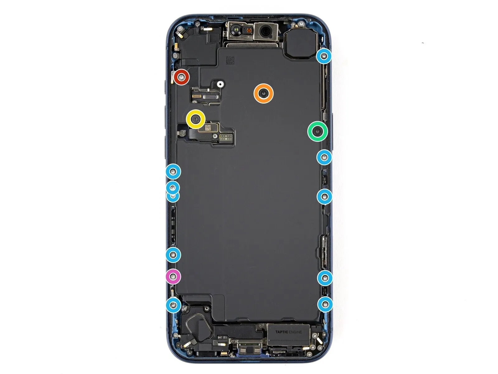
- Employ a Torx Plus 4IP screwdriver for the disassembly of screws that hold the battery tray in place.
A single fastener with a length of 7.5 millimeters is required.A solitary screw, measuring 5.9 millimeters in length, is also needed.
Additionally, utilize a screw that spans 3.5 millimeters in length.A screw with a 2.4-millimeter length is necessary for this procedure.
Ten screws, each with a length of 3.7 millimeters, are included in the assembly.A single 3.7-millimeter screw is also part of the required components.
Certain iPhone versions that incorporate a physical SIM card will lack this particular screw.The battery tray is fastened using a specific set of screws that must be carefully removed.
For proper removal, ensure the Torx Plus 4IP screwdriver is correctly seated on the screw heads.The length of each screw is critical for reassembly; note their positions during disassembly.
Models equipped with a physical SIM card omit the presence of one of the screws listed.Carefully observe the screw lengths to ensure correct replacement during reassembly.
Maintaining the original screw order is important for proper functionality and stability.
Step 25 | Remove the battery
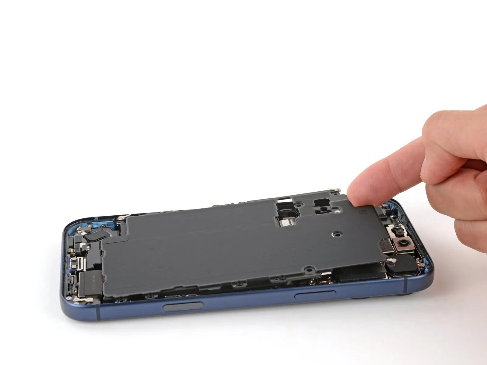
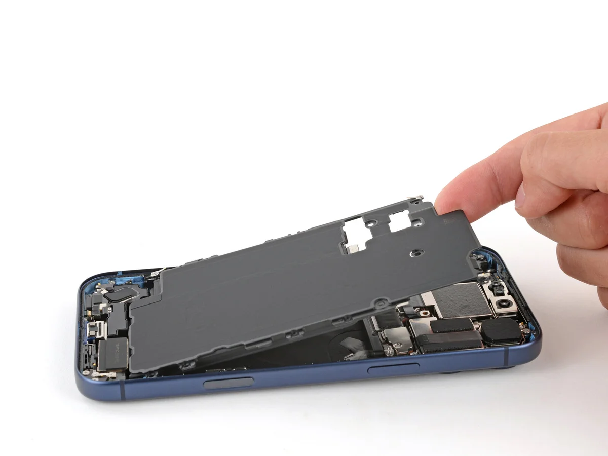

- Employing a fingertip, elevate the battery compartment's upper-left corner to facilitate its removal.
Exercise caution to prevent any smearing of the front-facing camera's lens.
Step 26 | Remove the top speaker
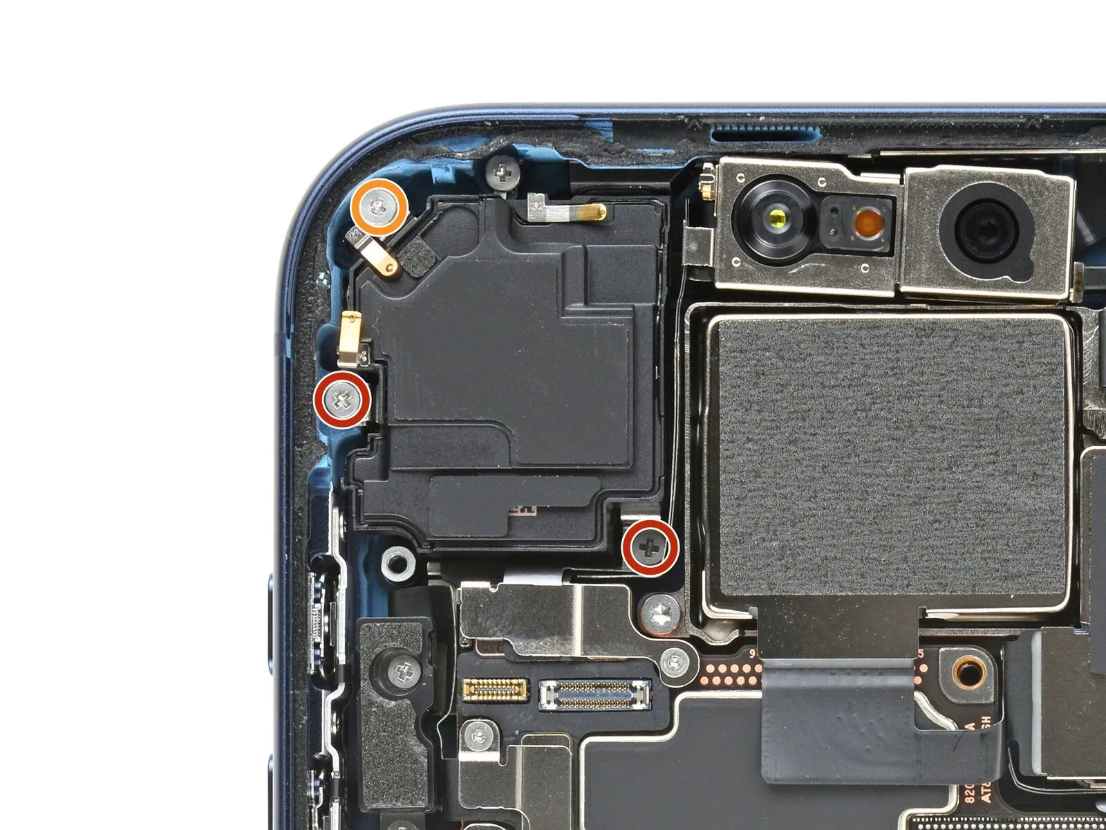
- Employ a JIS 00 screwdriver for the disassembly of the three screws that fasten the top speaker assembly.
A quantity of two screws, each measuring 2.4 millimeters in length, are present.The speaker components are also secured by a single screw with a length of 2.1 millimeters.Carefully unscrew the fasteners using the appropriate screwdriver to prevent damage to the surrounding components.
The JIS 00 screwdriver's specific size is essential for proper engagement and avoiding stripping the screw heads.Note the precise lengths of the screws (2.4 mm and 2.1 mm) for accurate reassembly.Ensure the screws are properly oriented during reinstallation to maintain the structural integrity of the speaker system.
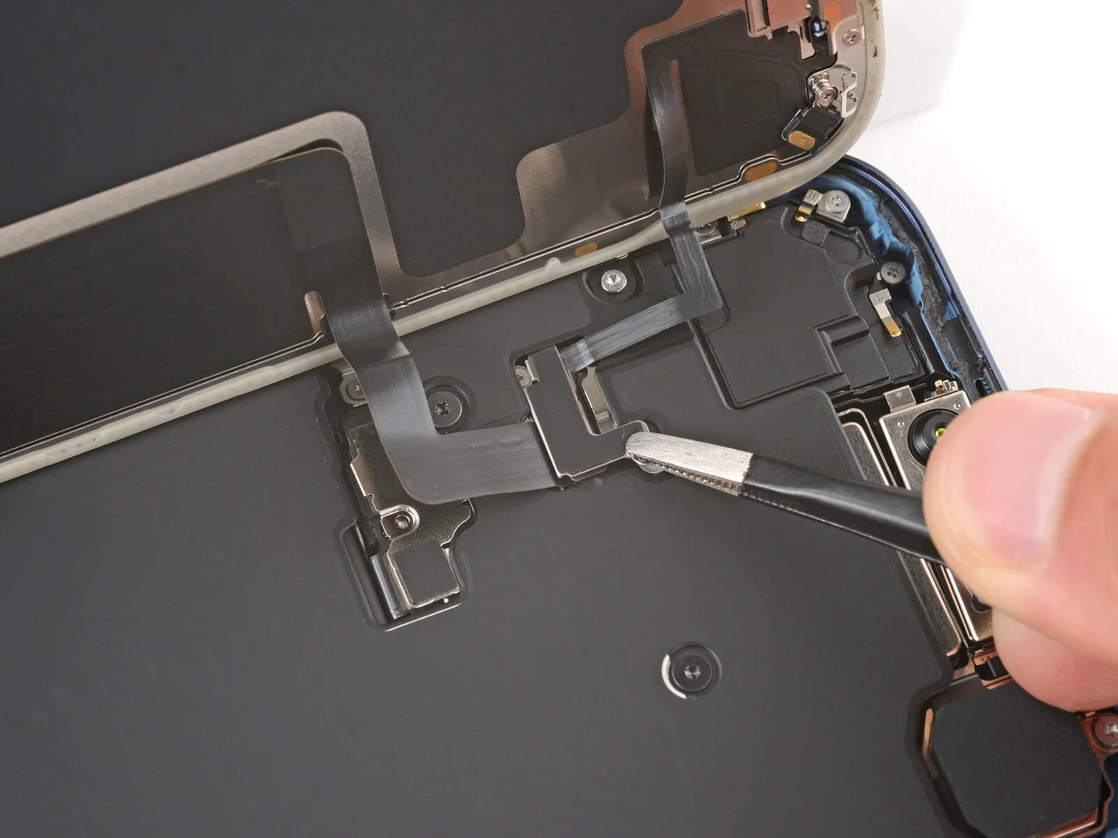
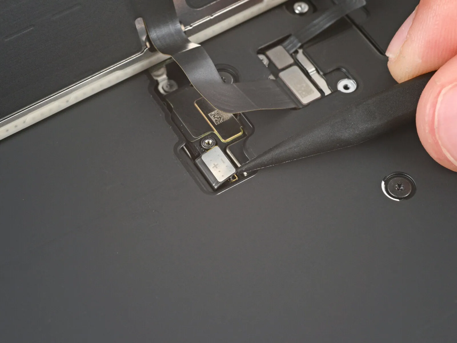
Step 27
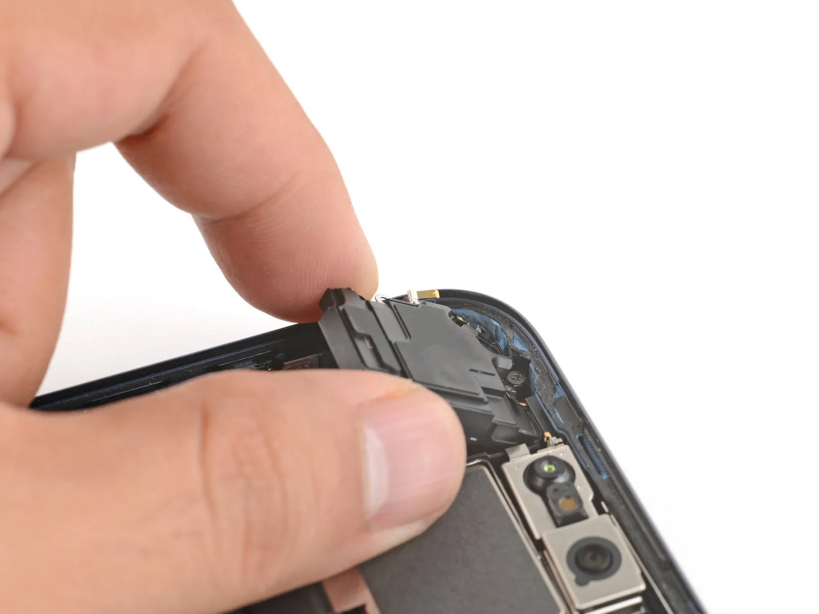

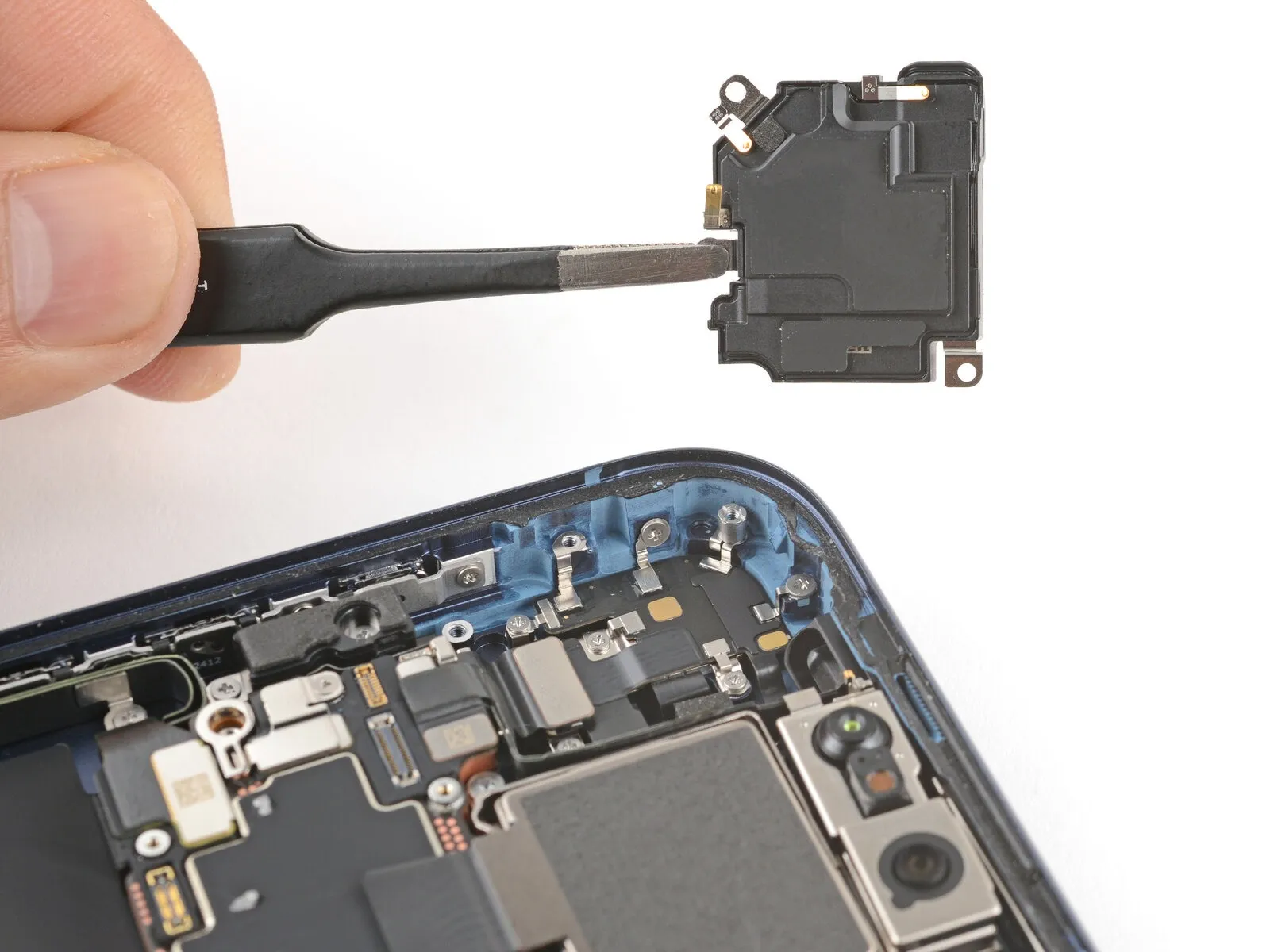
- Employ the tip of a spudger to gently separate and release the adhesive securing the upper speaker assembly.
- Detach the top speaker from its position within the device.
Step 28 | Disassembly complete

Having finished the disassembly process, the subsequent instructions detail the reassembly procedure for your iPhone.
Visual differences in the reassembly photographs might occur based on the specific iPhone model being serviced, but the outlined steps remain accurate for all variations.
Step 29 | Install the top speaker
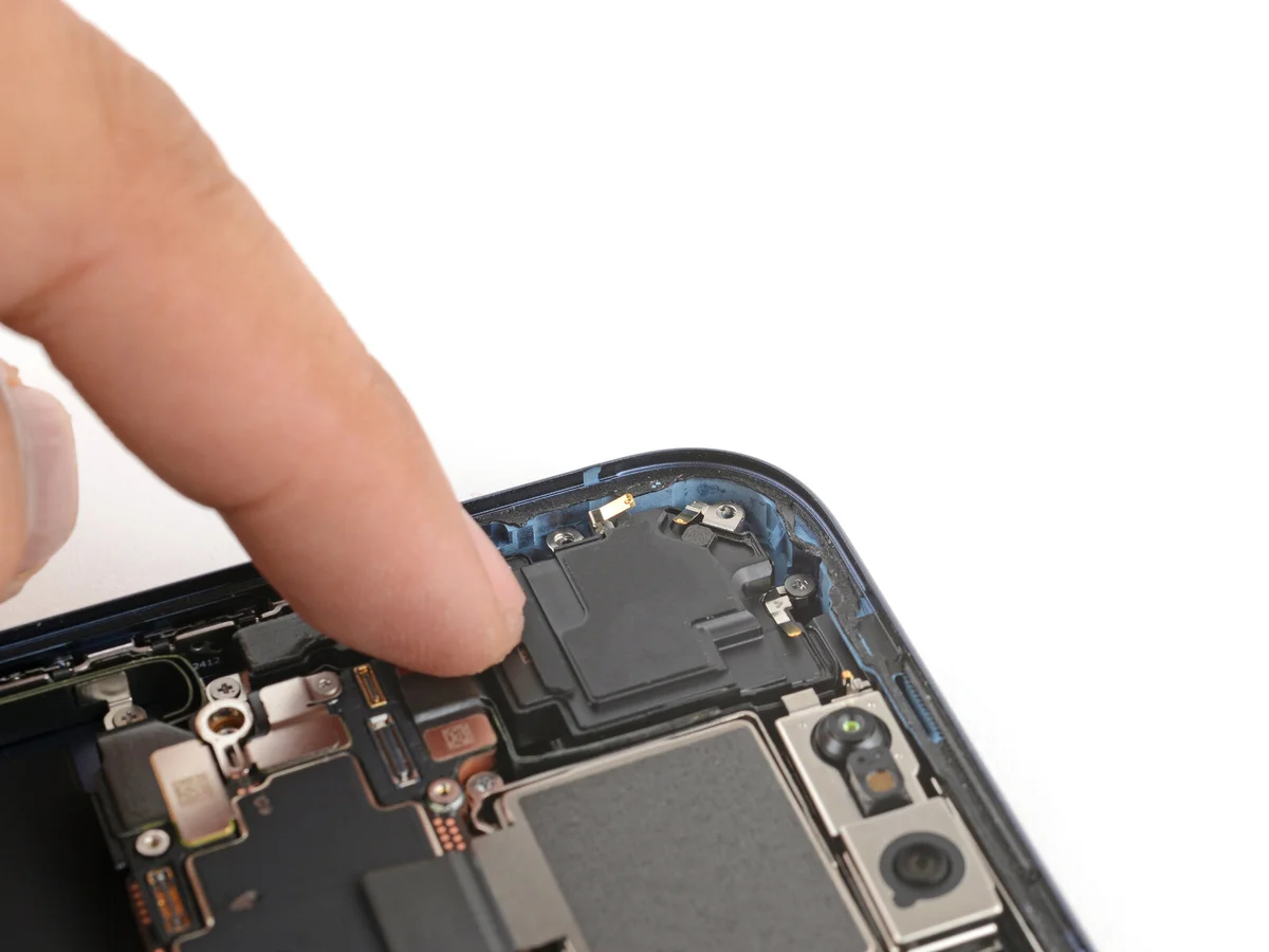
- Ensure the superior boundary of the top speaker is precisely positioned relative to the iPhone's casing.
- Carefully seat the speaker within its designated cavity.
Step 30
- Employ a JIS 00 screwdriver for the installation of the three screws securing the top speaker.The speaker's upper mounting utilizes two screws, each measuring 2.4 millimeters in length.A single screw, with a length of 2.1 millimeters, is also required for the speaker's attachment.
Secure the speaker assembly by carefully positioning and tightening the aforementioned screws.Ensure the JIS 00 screwdriver's proper engagement with the screw heads to prevent damage.
The three screws, differing in length, contribute to the speaker's stable and accurate placement.Proper screw length is critical; using incorrect sizes can compromise the speaker's structural integrity.
Step 31 | Install the battery
Position the battery tray correctly within the designated area.
Exercise caution to prevent any wires from becoming pinched or obstructed by the tray's placement.
Step 32 | Install the battery tray screws
Employ a Torx Plus 4IP screwdriver for the subsequent screw installations.A single screw, measuring 7.5 millimeters in length, is required.One screw, with a length of 5.9 millimeters, must be utilized.
- A 3.5-millimeter screw is also necessary for this process.A screw with a 2.4-millimeter length is needed.
- Ten screws, each 3.7 millimeters long, are part of the assembly.An additional 3.7-millimeter screw is included, though its presence depends on the iPhone model's SIM card configuration.
- Models equipped with a physical SIM card slot will not feature this particular screw.The Torx Plus 4IP screwdriver is essential for proper screw engagement.
- Ensure the screw lengths are precise to avoid damage during installation.Accurate screw placement is vital for maintaining device integrity.
- The 7.5 mm screw secures a critical component.The 5.9 mm screw contributes to structural stability.
- Carefully position the 3.5 mm screw to prevent interference.The 2.4 mm screw is used for a minor adjustment.
Step 33 | Clean the frame


Exercise caution when cleaning the frame, carefully avoiding damage to the delicate grounding clips; should a clip become displaced, restore its original shape with careful manipulation using your fingers or tweezers.
- Employing tweezers or your fingers, detach sizable portions of the adhesive material from the frame's edges.
- Employ a spudger to eliminate any remaining adhesive residue adhered to the frame's surface.
- Should the adhesive prove difficult to remove, utilize a hair dryer or heat gun to apply warmth, then attempt removal once more.
Step 34

To dissolve the remaining adhesive, dispense a small quantity of isopropyl alcohol with a purity exceeding 90%.
- Employing a microfiber cloth or a lint-free alternative, carefully remove the dissolved adhesive by wiping along the frame's edges in a single direction.
Step 35 | Clean the screen

To facilitate adhesion when reinstalling a display, utilize a microfiber or lint-free cloth dampened with a small quantity of isopropyl alcohol possessing a concentration exceeding 90%, and thoroughly clean the edges of the screen.
Step 36 | Orient the replacement adhesive


To ascertain the correct positioning of the adhesive layer, place it upon the frame's surface, ensuring that no protective liners are removed during this assessment.
- Employing elements like the camera aperture and indentations situated on the upper and lower borders of the frame will aid in visualizing the adhesive's intended placement.
Step 37 | Apply the replacement adhesive

Securely grasp the corner tab of the adhesive sheet's backing liner to initiate peeling, revealing approximately one-third of the adhesive surface.Exercise caution, as the newly exposed adhesive possesses a high degree of tackiness; prevent unintended contact with other surfaces until application to the frame is prepared.
- Should your adhesive component incorporate multiple layers of backing, proceed to remove the liner layer that reveals the adhesive intended for bonding to the frame.
- Initiate the peeling process by firmly grasping the corner tab of the adhesive sheet's liner.Carefully remove the liner to reveal a portion of the adhesive, specifically one-third of its total area.The exposed adhesive surface exhibits significant stickiness, necessitating careful handling to avoid premature adhesion to unintended objects.
Step 38


After applying pressure to secure the adhesive, adjustments are impossible, necessitating removal and replacement with fresh adhesive material.To ensure proper bonding, the visible portion of the adhesive strip must be precisely matched with the iPhone frame's designated boundary.
- Correct positioning is achieved when the adhesive strip's edge is accurately aligned with the iPhone's frame edge.
- Apply slight, even pressure to the exposed adhesive strip to create a secure bond with the iPhone's frame following proper alignment.
Step 39


Progressively remove the protective liner from the adhesive backing while applying even pressure to secure it.The adhesive should adhere firmly when properly positioned.
- Accurate alignment is indicated when the adhesive edges seat seamlessly within the frame's contours.
- Should minor displacement occur during placement,carefully reposition the extended borders to match the frame's geometry.
- Should the adhesive develop folds or distortions, discard it and apply a new strip.
- In the absence of replacement adhesive strips, the iPhone can be reassembled and used temporarily; however, be aware that its water resistance will be diminished until the adhesive is replaced.
Step 40

Employ a spudger to apply pressure on the adhesive securing the iPhone's edges.Carefully maneuver around the delicate grounding clips, as displacement can occur.
- Should a grounding clip become bent, restore its original shape with careful manipulation using your fingers or tweezers.
Step 41


Detach the extensive front adhesive liner by grasping the designated pull tab, typically found positioned within a corner of the liner.
- Remaining liners will persist along the device's edges at this stage.
- Refrain from removing these liners presently, as their purpose is to inhibit premature adhesion during the iPhone reassembly process.
Step 42 | Connect the screen

Position the iPhone display adjacent to the frame, ensuring sufficient cable slack to connect to the logic board.
Step 43


Employing either a fingertip or the broad, planar edge of a spudger tool, establish a secure physical connection between the two screen connectors and the logic board.Avoid applying excessive pressure when aligning the connectors; a gentle touch is sufficient.Should difficulties arise during the connection process, slightly adjust the connector's position and attempt the attachment once more.
- Proper seating of the connectors is essential for device functionality; ensure a firm, even contact.
- Persistent issues indicate a potential misalignment; careful repositioning and reattempting the connection are advised.
Step 44 | Connect the battery


Employing either a fingertip or the planar edge of a spudger tool, establish a secure physical connection between the battery connector and the logic board surface.Ensure the battery connector makes firm contact with the designated area on the logic board using a finger or a spudger's flat end.To join the battery connector to the logic board, apply pressure with a finger or the broad, flat portion of a spudger.
Step 45 | Test your repair

Prior to final enclosure, it's advisable to verify the functionality of the completed iPhone repair.
- Confirm proper operation by activating the iPhone and observing expected behavior.
- Deactivate the device and proceed with the remaining assembly steps.
- Should the iPhone fail to energize, establish a connection to a power supply and attempt another activation.
Step 46 | Install the battery connector cover


- Carefully slide the upper border of the battery connector cover beneath the designated edge.
- Verify that each of the two tabs is securely positioned beneath the lip.
- Position the cover precisely using the screw aperture as a guide, then set it down.
Step 47

Employ a JIS 00 screwdriver for the installation of the screw.The screw utilized for securing the battery connector cover possesses a length of 1.2 mm.To fasten the battery connector cover, a JIS 00 screwdriver is required.A 1.2 mm screw is designated for the purpose of securing the battery connector cover.Installation of the battery connector cover necessitates the use of a JIS 00 screwdriver and a 1.2 mm screw.
Step 48 | Install the screen connector cover


- Carefully slide the left side of the screen connector cover beneath the designated notch.
- Position the cover precisely using the screw aperture as a guide, then set it down onto the device.
Step 49

Employ a JIS 00 screwdriver for the installation process.A 1.2 mm screw length is required for proper fastening.The screen connector cover necessitates secure attachment.Utilize the screwdriver to engage the screw head.This screw secures the cover, maintaining the screen connector's integrity.
Step 50 | Remove the final adhesive liners


- Maintain the screen's stability by grasping it firmly with one hand.
Employing either your fingertips or a spudger, carefully separate the perimeter liners to reveal the underlying adhesive.
Prevent any contact with the newly exposed adhesive to maintain its integrity.
Thoroughly inspect the internal components, eliminating any detached liners to guarantee complete adhesive exposure.
Step 51 | Install the screen


Position the display assembly onto the chassis, initiating the alignment process from the uppermost border.
Should you encounter opposition during placement, a surrounding retaining clip might be deformed and experiencing compression from the chassis; carefully examine the area of obstruction and delicately restore any bent clips to their original shape.
Verify that the display's periphery isn't exerting pressure on any connected wires or connectors.
Apply even pressure across the iPhone's borders to ensure the display makes complete contact with the chassis.
Step 52


Apply consistent, substantial pressure encompassing the complete circumference of the iPhone's housing.
Step 53 | Apply heat to the perimeter

Employ a hair dryer, heat gun, or iOpener to warm the screen's edges.Apply heat to the screen's boundary until the surface reaches a temperature just beyond comfortable touch.This warming process reduces the adhesive's viscosity.The heat facilitates separation of the adhesive bond.Softening the adhesive improves the potential for a renewed bond during reassembly.Ensure the temperature does not exceed a level that could damage the display or surrounding components.The tools listed provide controlled heat application for this process.
Carefully monitor the temperature to prevent overheating and potential damage.
Step 54 | Install the pentalobe screws
Employ a P2 pentalobe screwdriver for the installation of the two screws, each measuring 7.5 mm in length, positioned on both sides of the charging port.The two screws securing the charging port are each 7.5 mm long and require a P2 pentalobe screwdriver for proper installation.To affix the screws flanking the charging port, utilize a P2 pentalobe screwdriver, ensuring each screw is 7.5 mm in length.