iPhone 3G Mute Button Replacement
The iPhone's switch allows selection between vibration and audible ring notifications.
Step 1 | Broken Glass
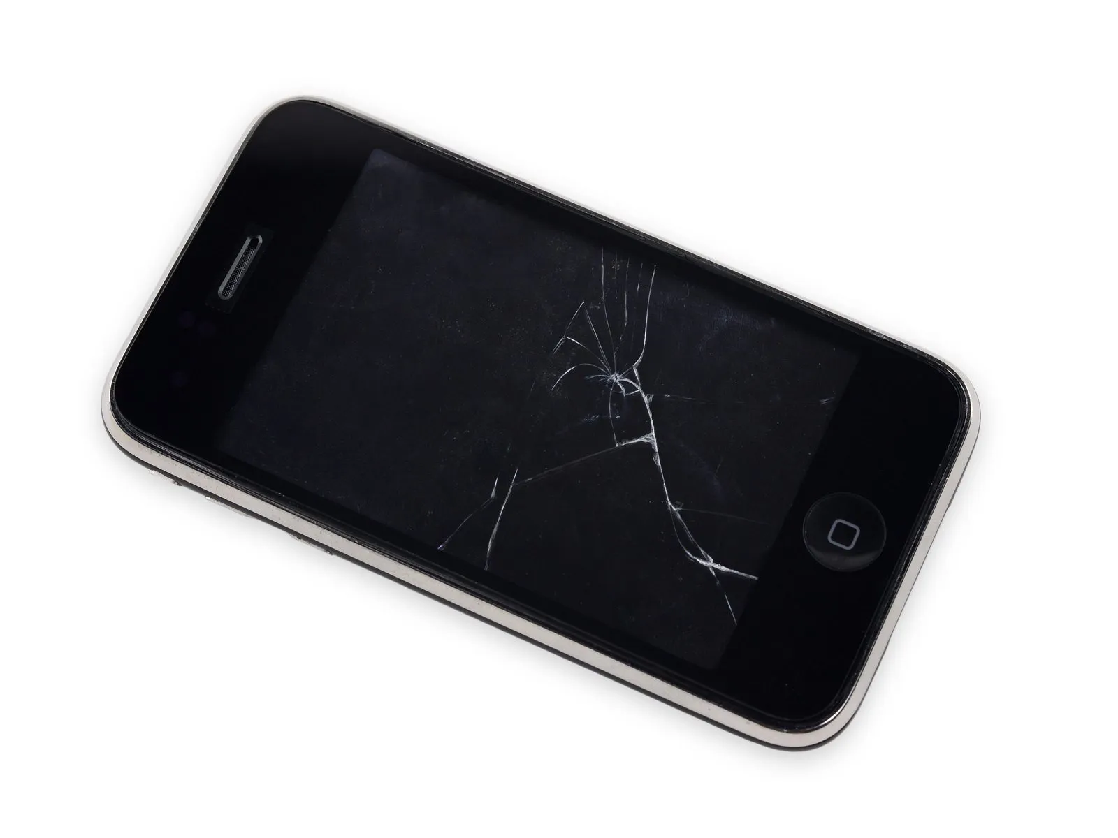
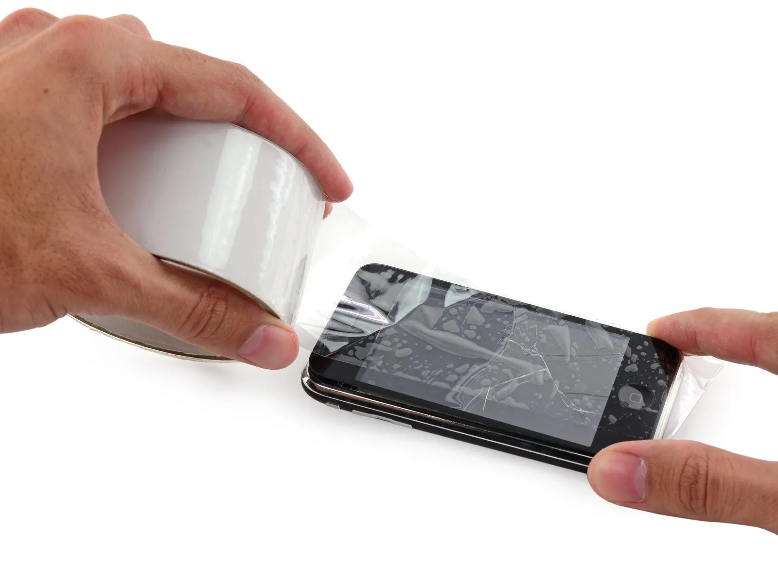
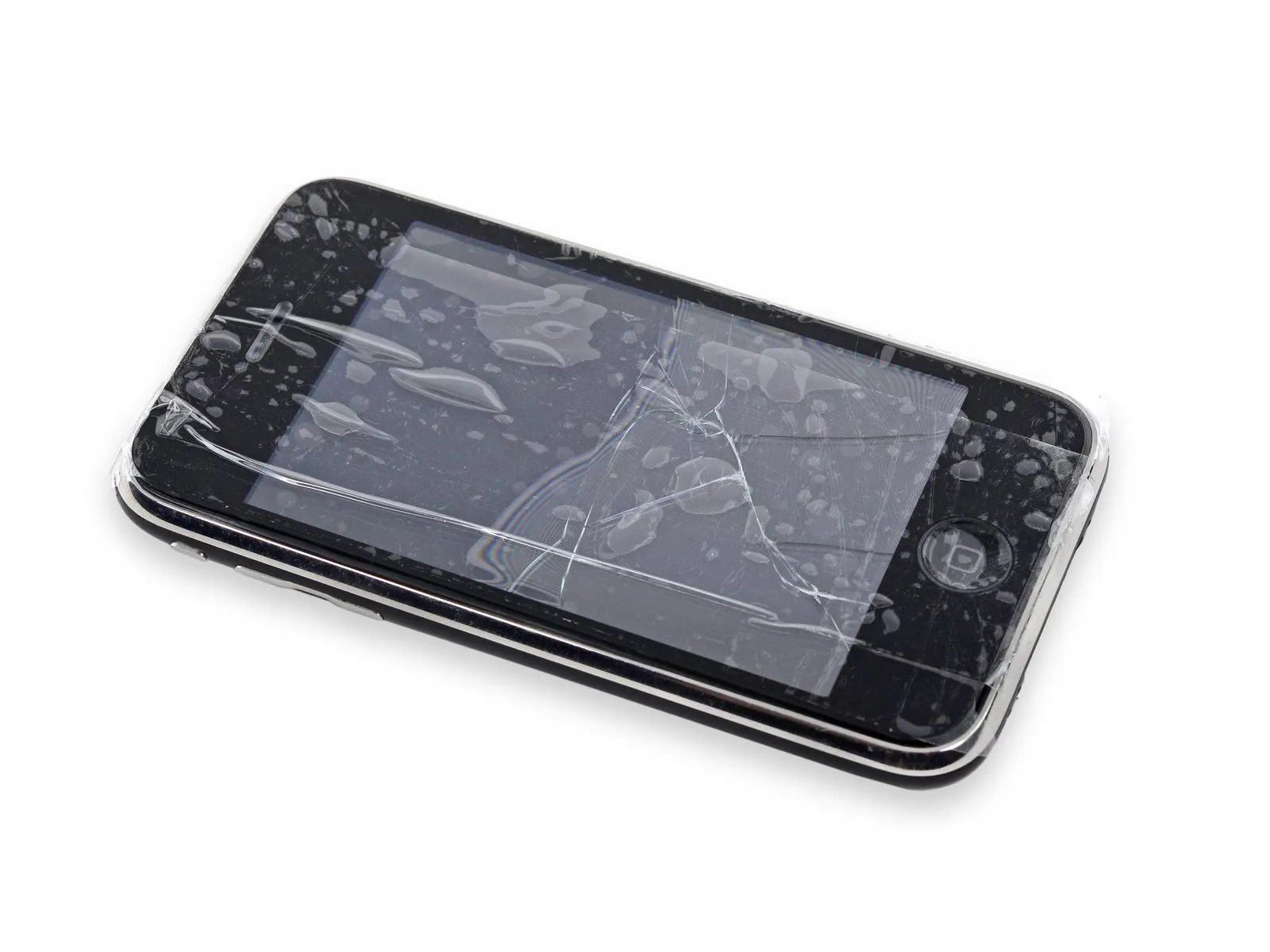
To minimize additional shattering and protect yourself from injury while working, secure any cracked display glass with tape.
Apply clear packing tape across the iPhone's screen surface, ensuring each strip overlaps the previous one to completely protect the display.
To prevent scattered glass fragments and maintain stability during the display separation process, this technique is essential.
To safeguard your vision, always use safety glasses when performing this repair, as fragments of glass may become dislodged.
Apply clear packing tape across the iPhone's screen surface, ensuring each strip overlaps the previous one to completely protect the display.
To prevent scattered glass fragments and maintain stability during the display separation process, this technique is essential.
To safeguard your vision, always use safety glasses when performing this repair, as fragments of glass may become dislodged.
Step 2 | Remove the bottom screws
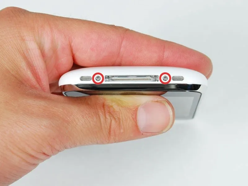
Using a Phillips #00 screwdriver, detach the two screws, each measuring 3.7mm, located at the dock connector interface.
Step 3 | Loosen the display
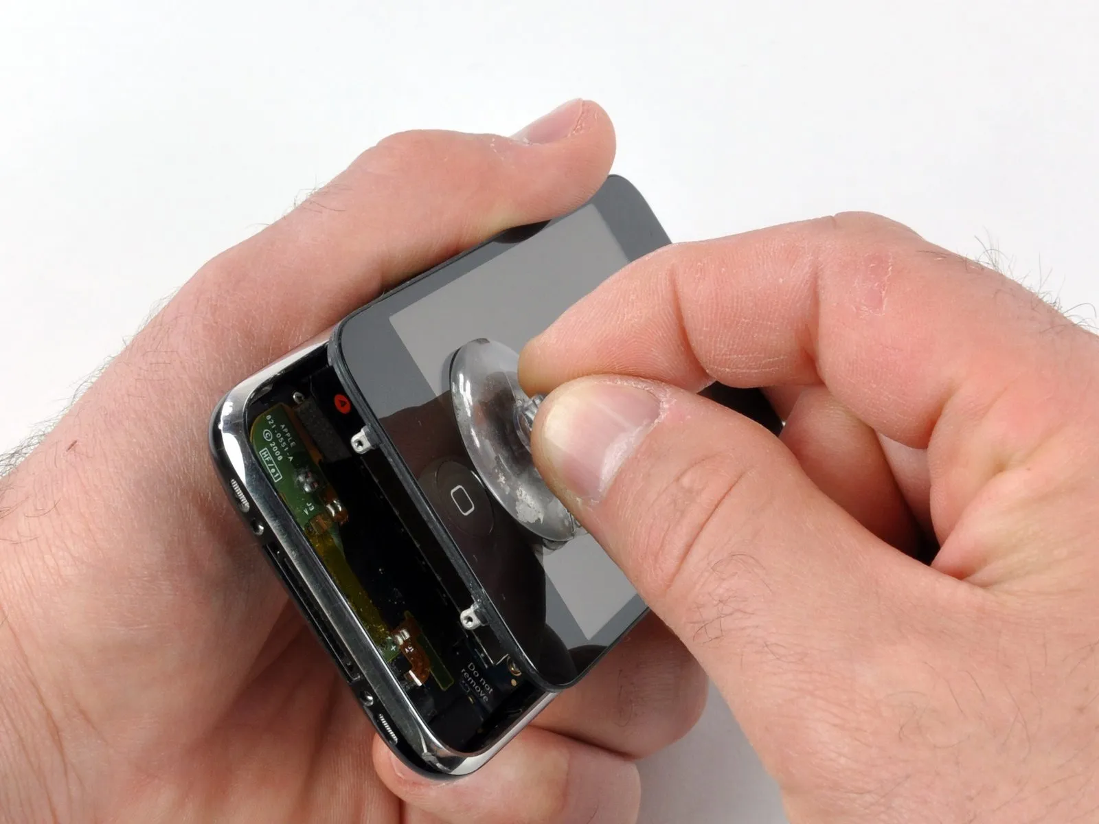
For improved handling and safety, detach the metal handle from the suction cup; gripping the base of the suction cup directly provides a more secure hold.
Exercise extreme caution during iPhone disassembly to prevent damage to the delicate display cables.
A rubber gasket is situated where the silver front bezel meets the black display assembly; separating these components necessitates applying moderate pressure. To ease removal, gently oscillating a suction cup can be beneficial.
Carefully lift the lower edge of the iPhone's display assembly by applying gentle upward pressure with a small suction cup positioned close to the Home button.
When the display assembly's surface prevents proper suction cup attachment due to damage, secure it with a robust adhesive tape like duct tape or packing tape.
Exercise extreme caution during iPhone disassembly to prevent damage to the delicate display cables.
A rubber gasket is situated where the silver front bezel meets the black display assembly; separating these components necessitates applying moderate pressure. To ease removal, gently oscillating a suction cup can be beneficial.
Carefully lift the lower edge of the iPhone's display assembly by applying gentle upward pressure with a small suction cup positioned close to the Home button.
When the display assembly's surface prevents proper suction cup attachment due to damage, secure it with a robust adhesive tape like duct tape or packing tape.
Step 4 | Pull up the display
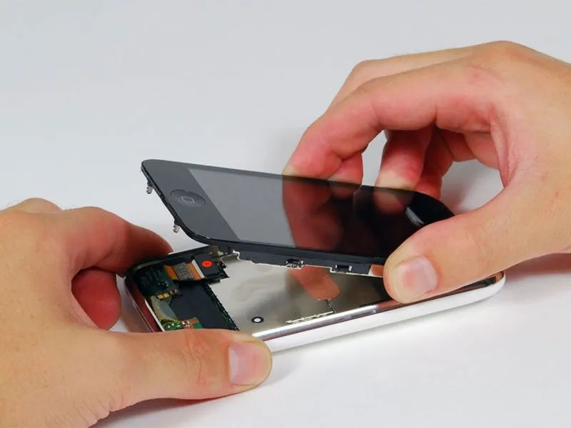
Because multiple cables secure the display assembly to the iPhone's internal components, avoid separating them completely at this stage.
Tilt the display assembly upwards, achieving roughly a 45-degree angle.
Tilt the display assembly upwards, achieving roughly a 45-degree angle.
Step 5 | Disconnect cable 1
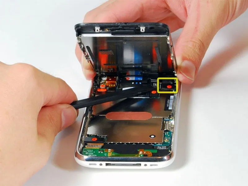
Before fully separating the display assembly from the iPhone, be aware that multiple cables maintain the connection and attempting to do so prematurely could cause damage.
Tilt the display assembly upwards, achieving roughly a 45-degree angle.
Using one hand to secure the display assembly, employ a spudger with your other hand to carefully detach the ribbon cable identified as "1"—this cable specifically connects to the display.
To prevent damage requiring display replacement, carefully guide the spudger beneath the ribbon cable, accessing it from the left side, referencing the provided image for proper placement. Attempting to lift the ribbon from the right risks damaging the ribbon connector.
Tilt the display assembly upwards, achieving roughly a 45-degree angle.
Using one hand to secure the display assembly, employ a spudger with your other hand to carefully detach the ribbon cable identified as "1"—this cable specifically connects to the display.
To prevent damage requiring display replacement, carefully guide the spudger beneath the ribbon cable, accessing it from the left side, referencing the provided image for proper placement. Attempting to lift the ribbon from the right risks damaging the ribbon connector.
Step 6 | Disconnect cable 2
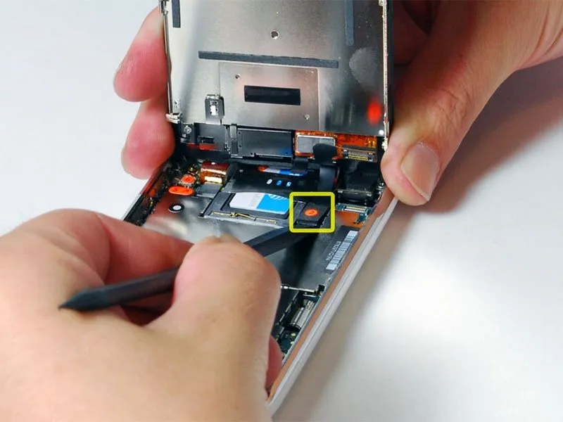
Adjust the display assembly's orientation to a near-vertical position to simplify the process of disconnecting the remaining cables.
Carefully detach the ribbon cable identified as "2"—which connects to the capacitive touch panel—using a spudger.
Carefully detach the ribbon cable identified as "2"—which connects to the capacitive touch panel—using a spudger.
Step 7 | Disconnect cable 3
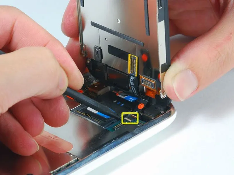
Certain international (Chinese, European) 3G models lack the plastic retaining tab; instead, to detach the ribbon cable, slide it screen-ward. During reassembly, ensure the ribbon cable is firmly seated within its connector by applying consistent pressure.
Connector "3" on certain iPhone models exhibits an inverted color scheme, with a black plastic tab and a white connector; ensure the tab is lifted correctly to prevent connector damage.
Employ a spudger to lift the white plastic retaining tab, which secures ribbon cable "3," rotating it upward by 90 degrees to disengage the cable.
Carefully disconnect the black ribbon cable by sliding it from its connector, then detach the display assembly from the iPhone.
Connector "3" on certain iPhone models exhibits an inverted color scheme, with a black plastic tab and a white connector; ensure the tab is lifted correctly to prevent connector damage.
Employ a spudger to lift the white plastic retaining tab, which secures ribbon cable "3," rotating it upward by 90 degrees to disengage the cable.
Carefully disconnect the black ribbon cable by sliding it from its connector, then detach the display assembly from the iPhone.
Step 8 | Remove the SIM card tray
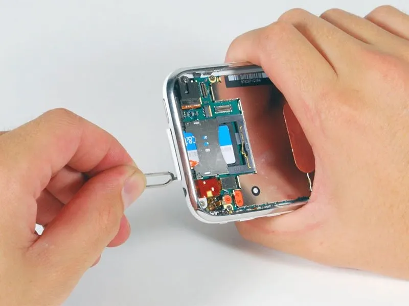
Using a SIM eject tool or a straightened paper clip, gently push into the small aperture located adjacent to the headphone jack.
Apply pressure to the tool, ensuring it extends the SIM card tray until it disengages.
Using your fingers, gently eject the SIM card tray from the iPhone by sliding it outward.
Apply pressure to the tool, ensuring it extends the SIM card tray until it disengages.
Using your fingers, gently eject the SIM card tray from the iPhone by sliding it outward.
Step 9 | Disconnect cable 4
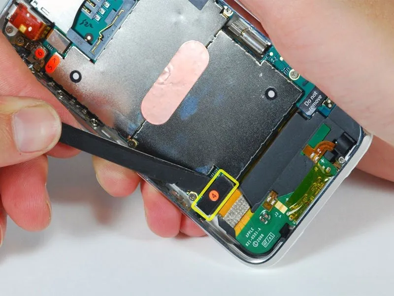
Carefully detach the ribbon cable identified as "4" using a spudger.
Step 10 | Disconnect cable 5
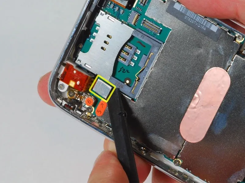
Carefully detach the ribbon cable identified as "5" using a spudger.
Step 11 | Disconnect cables 6 and 7
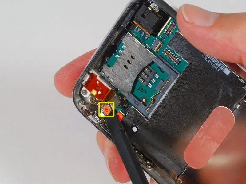
Carefully detach the ribbon cable identified as "6" using a spudger.
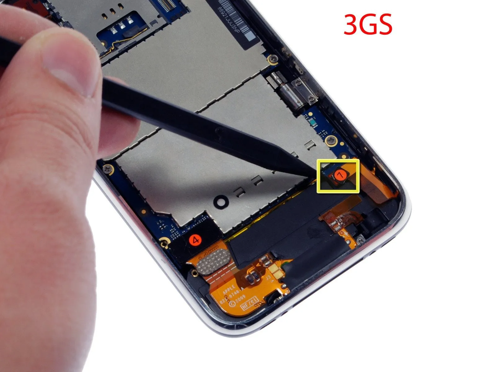
For iPhone 3GS models, consult the provided image and employ a spudger to carefully detach the ribbon cable identified as "7".
Carefully position the ribbon cable connectors so they match the motherboard sockets precisely before applying any force; visual inspection with a magnifying glass or jeweler's loupe may be necessary to ensure proper alignment.
For iPhone 3GS models, consult the provided image and employ a spudger to carefully detach the ribbon cable identified as "7".
Carefully position the ribbon cable connectors so they match the motherboard sockets precisely before applying any force; visual inspection with a magnifying glass or jeweler's loupe may be necessary to ensure proper alignment.
Step 12 | Remove the logic board screws
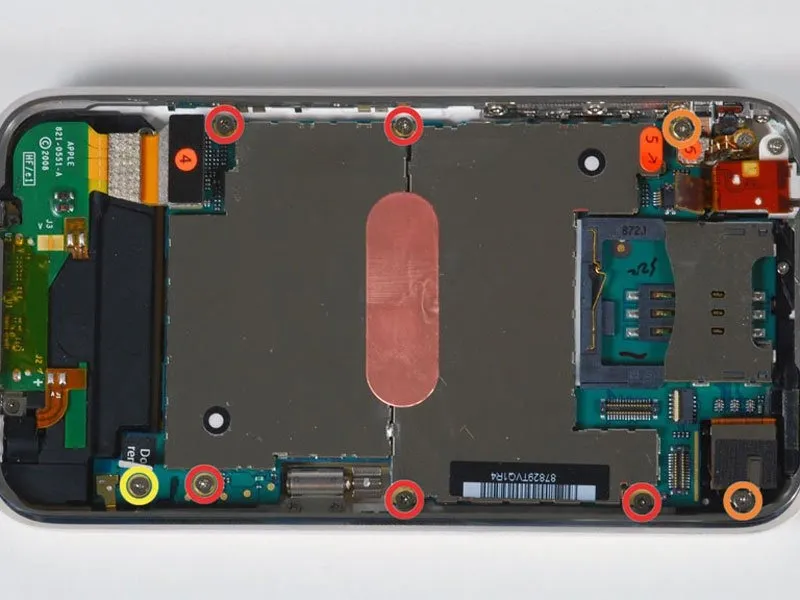
Using the appropriate screwdriver, detach the eight screws.
The logic board is affixed to the rear case using five screws; each is 2.3 mm in length, features a Phillips #00 head, and has partial threads.
Use two Phillips #00 screwdrivers to fasten the logic board and camera, employing 2.3 mm screws with full threads for secure attachment.
Locate the "Do not remove" sticker and, underneath it, you'll find a 2.9 mm Phillips #00 screw.
When putting everything back together, ensure that the 1/4-20 x 1-1/2-inch bolt is secured with a torque of 18-22 ft-lbs, and that the retaining clip is properly seated in the groove to prevent dislodgement; failure to do so could result in component failure.
Located on the lower right side of the device, near the camera, an orange highlight indicates a screw securing a metal bracket that stabilizes the camera's position.
Before securing the camera with the fully threaded Phillips #00 screw, measuring 2.3 mm, ensure the strip is correctly positioned.
The logic board is affixed to the rear case using five screws; each is 2.3 mm in length, features a Phillips #00 head, and has partial threads.
Use two Phillips #00 screwdrivers to fasten the logic board and camera, employing 2.3 mm screws with full threads for secure attachment.
Locate the "Do not remove" sticker and, underneath it, you'll find a 2.9 mm Phillips #00 screw.
When putting everything back together, ensure that the 1/4-20 x 1-1/2-inch bolt is secured with a torque of 18-22 ft-lbs, and that the retaining clip is properly seated in the groove to prevent dislodgement; failure to do so could result in component failure.
Located on the lower right side of the device, near the camera, an orange highlight indicates a screw securing a metal bracket that stabilizes the camera's position.
Before securing the camera with the fully threaded Phillips #00 screw, measuring 2.3 mm, ensure the strip is correctly positioned.
Step 13 | Loosen the camera
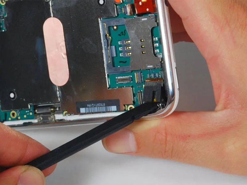
Carefully leverage the camera assembly from its rear case mounting with a spudger, ensuring no forceful movements are applied.
Due to its connection to the logic board's base, complete camera removal is currently not possible.
Due to its connection to the logic board's base, complete camera removal is currently not possible.
Step 14 | Remove the logic board
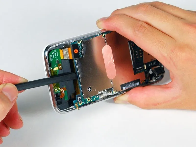
Carefully lift the logic board's edge nearest the dock connector using a spudger, applying gentle force.
Near the 'do not remove' label on the logic board, a fragile, small gold grounding tab is located; exercise extreme caution to prevent it from catching on the device casing during logic board removal, as it is prone to breakage. Post-removal signal issues may indicate a damaged ground tab, requiring inspection.
Verify that each of the screws holding the logic board in place has been completely unscrewed if you encounter resistance when attempting to separate it.
Near the 'do not remove' label on the logic board, a fragile, small gold grounding tab is located; exercise extreme caution to prevent it from catching on the device casing during logic board removal, as it is prone to breakage. Post-removal signal issues may indicate a damaged ground tab, requiring inspection.
Verify that each of the screws holding the logic board in place has been completely unscrewed if you encounter resistance when attempting to separate it.
Step 15
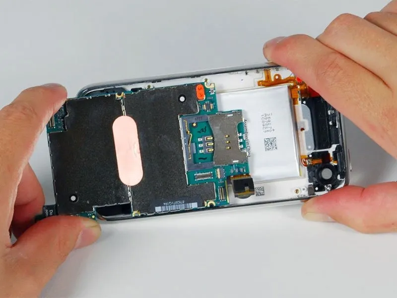
Carefully advance the logic board in the direction of the dock connector to disengage it from the iPhone's chassis.
Before securing the logic board within the device enclosure following battery installation, attach the camera connector to the board. Ensure proper alignment of the logic board’s upper portion—specifically, the area containing the SIM tray—before fully positioning the entire board. Failure to do so may result in SIM tray misalignment. After the upper section is correctly situated, the remaining portion of the board can be adjusted for final placement. Confirm correct installation by verifying that the SIM tray aligns precisely with the iPhone case opening and the camera module is flush within its socket.
Before securing the logic board within the device enclosure following battery installation, attach the camera connector to the board. Ensure proper alignment of the logic board’s upper portion—specifically, the area containing the SIM tray—before fully positioning the entire board. Failure to do so may result in SIM tray misalignment. After the upper section is correctly situated, the remaining portion of the board can be adjusted for final placement. Confirm correct installation by verifying that the SIM tray aligns precisely with the iPhone case opening and the camera module is flush within its socket.
Step 16 | Loosen the battery
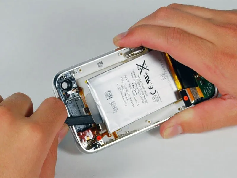
Carefully align the 4mm hex key to the setscrew and tighten it to a torque of 1.5 Nm using the torque wrench.
- Carefully lift the battery away from the rear case using a spudger, as it is secured by an adhesive strip that runs along its edges.
- Employing solely the provided plastic pull-tab to detach the battery risks causing deformation; therefore, avoid this practice.
- Disconnecting the battery isn't required to replace the GPS antenna; however, doing so provides greater clearance when removing the headphone assembly, a step that isn't essential for the antenna replacement itself.
- The iPhone battery is secured to the rear enclosure using a low-strength adhesive, which typically remains adhered to the battery during removal. If your new battery has pre-applied adhesive, no further action is needed; otherwise, carefully move the adhesive from the original battery to the replacement.
- To release a battery that is sticking to the back cover, carefully introduce a small amount of isopropyl alcohol with a concentration exceeding 90% between the battery's edge and the case. Permit approximately one minute for the alcohol to dissolve the adhesive bond, then use the spudger's flat end to delicately pry the battery loose. Ensure the alcohol completely evaporates before proceeding with the new battery installation.
- To prevent damage, avoid using excessive force when removing the battery. Should the battery remain difficult to dislodge, add additional alcohol drops to dissolve the adhesive. Ensure the pry tool does not compromise the battery's structural integrity by bending or puncturing it.
- To facilitate battery separation, apply gentle heat to the case's rear surface using a hair dryer or heat gun, ensuring the setting is at its lowest level; this softens the adhesive securing the battery.
- To prevent battery ignition, avoid exposing the iPhone to excessive heat.
Step 17 | Headphone Jack

Carefully align the 4mm hex key to the setscrew, ensuring it engages fully, then tighten the setscrew to a torque of 1.5 Nm using the torque wrench.
- Using a Phillips #00 screwdriver, detach the on/off switch from the front bezel by unscrewing the two screws that hold it in place.
- Verify the switch's extension during replacement; a thin plastic spacer is affixed inside the button and could detach during cleaning. Absence of this spacer may result in insufficient button projection for proper operation, so if it's missing, substitute with a piece of rigid plastic approximately the same thickness—such as material from a shirt box lid—to compensate.
Step 18

Using a 5/32-inch hex key, carefully tighten the four M4x8mm screws securing the fan assembly to the heatsink, ensuring each is snug but not over-tightened to prevent damage.
Gently lift the orange ribbon cable away from the back cover, exercising caution.
Exercise extreme caution when handling the ribbon cable, as it is susceptible to damage.
Gently lift the orange ribbon cable away from the back cover, exercising caution.
Exercise extreme caution when handling the ribbon cable, as it is susceptible to damage.
Step 19
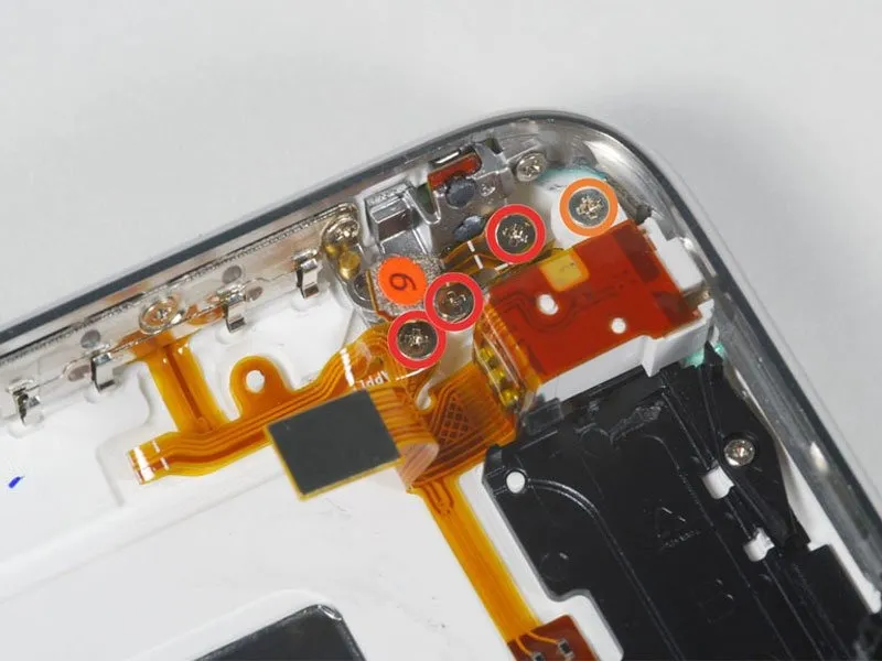
Using a 5/32-inch hex key, carefully tighten the four M4x8 socket head cap screws securing the fan assembly to the heatsink, ensuring a torque of 4.5 in-lbs to prevent damage.
Using the appropriate screwdriver, detach the four screws.
To detach the headphone jack and GPS antenna assembly from the rear case, carefully unscrew three Phillips #00 screws—observe their sequence during removal, as the screw on the left side features a marginally larger head.
A plastic loop situated close to the headphone jack secures a 3.8 mm Phillips #00 screw.
Using the appropriate screwdriver, detach the four screws.
To detach the headphone jack and GPS antenna assembly from the rear case, carefully unscrew three Phillips #00 screws—observe their sequence during removal, as the screw on the left side features a marginally larger head.
A plastic loop situated close to the headphone jack secures a 3.8 mm Phillips #00 screw.
Step 20

Using a 5/32-inch hex key, carefully tighten the four M4x8 screws securing the fan assembly to the heatsink, ensuring a torque of no more than 4 in-lbs to prevent damage to the threads.
Using a Phillips #00 screwdriver, detach the volume and mute switch assembly by unscrewing the four screws that hold it in place.
The mute switch assembly is located directly beneath the volume switch assembly; during disassembly, carefully retain the small, pliable cushioning pad affixed to the mute switch, as its absence will result in a loose fit upon reassembly.
Ensure the mute switch is set to the "off" state while tightening its screws. Verify the switch's extension when activated; insufficient projection, indicating improper alignment of the assembly, can hinder operation. Examine the space between the switch frame and the bezel—specifically, the visible gap between the two screws located near the 6 o'clock position—to confirm correct positioning. Note that one screw is longer than the remaining three and account for this during reassembly.
Using a Phillips #00 screwdriver, detach the volume and mute switch assembly by unscrewing the four screws that hold it in place.
The mute switch assembly is located directly beneath the volume switch assembly; during disassembly, carefully retain the small, pliable cushioning pad affixed to the mute switch, as its absence will result in a loose fit upon reassembly.
Ensure the mute switch is set to the "off" state while tightening its screws. Verify the switch's extension when activated; insufficient projection, indicating improper alignment of the assembly, can hinder operation. Examine the space between the switch frame and the bezel—specifically, the visible gap between the two screws located near the 6 o'clock position—to confirm correct positioning. Note that one screw is longer than the remaining three and account for this during reassembly.
Step 21

Gently separate the volume button electrical components from the iPhone's side, then meticulously detach the orange ribbon cable from the back housing, exercising caution as it is delicate and prone to damage.
Step 22

Gently raise the headphone jack component from its position within the iPhone, ensuring no force is applied.
To facilitate installation of the replacement mute button, move the green mute switch located on the rear of the iPhone to the muted setting.
To facilitate installation of the replacement mute button, move the green mute switch located on the rear of the iPhone to the muted setting.
Step 23 | Mute Button
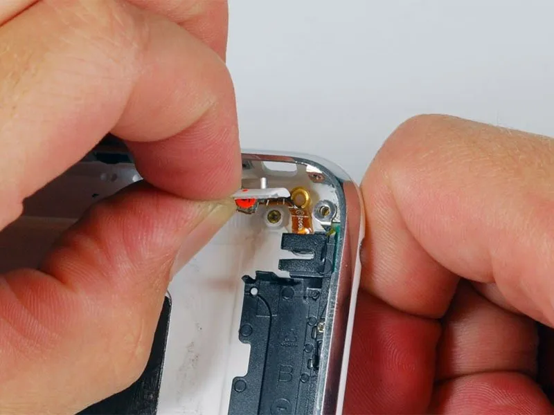
Carefully extract the mute button from the iPhone's housing.