iPhone 3G Vibrator Replacement
The iPhone's linear actuator, responsible for haptic feedback, is the component that vibrates.
Step 1 | Broken Glass
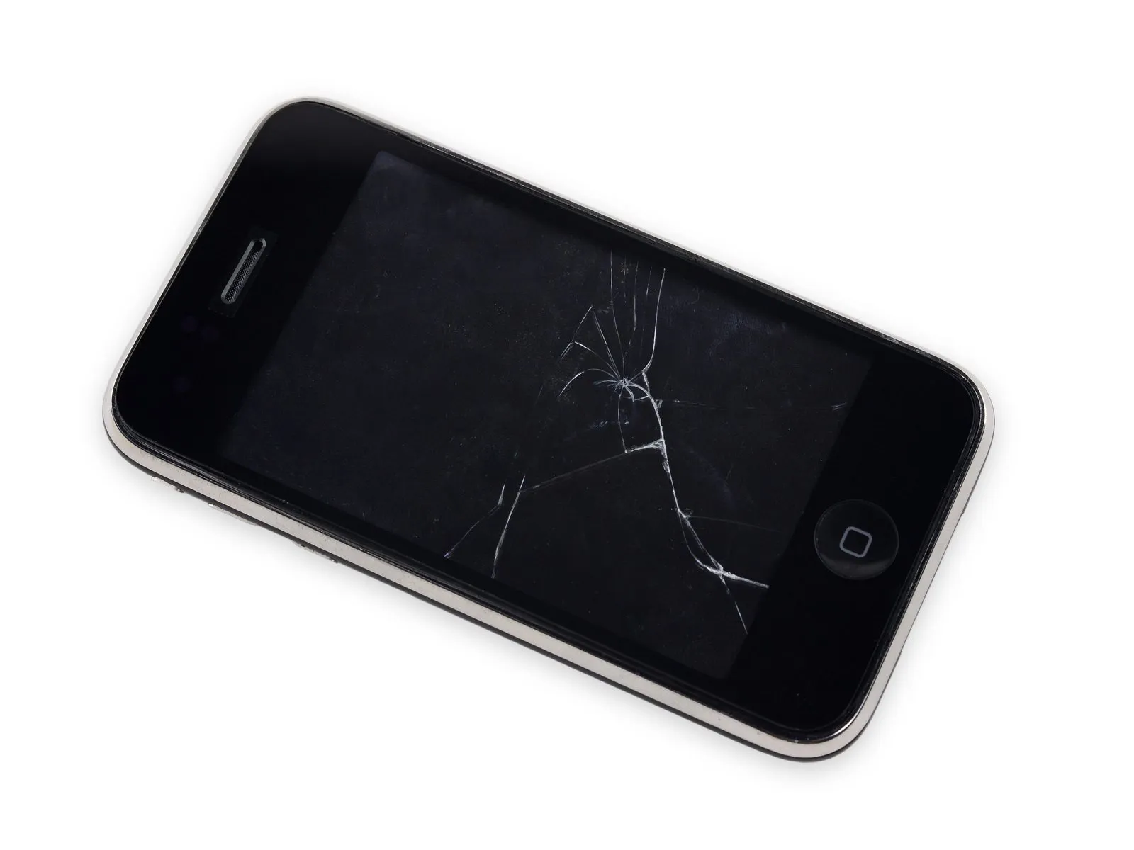
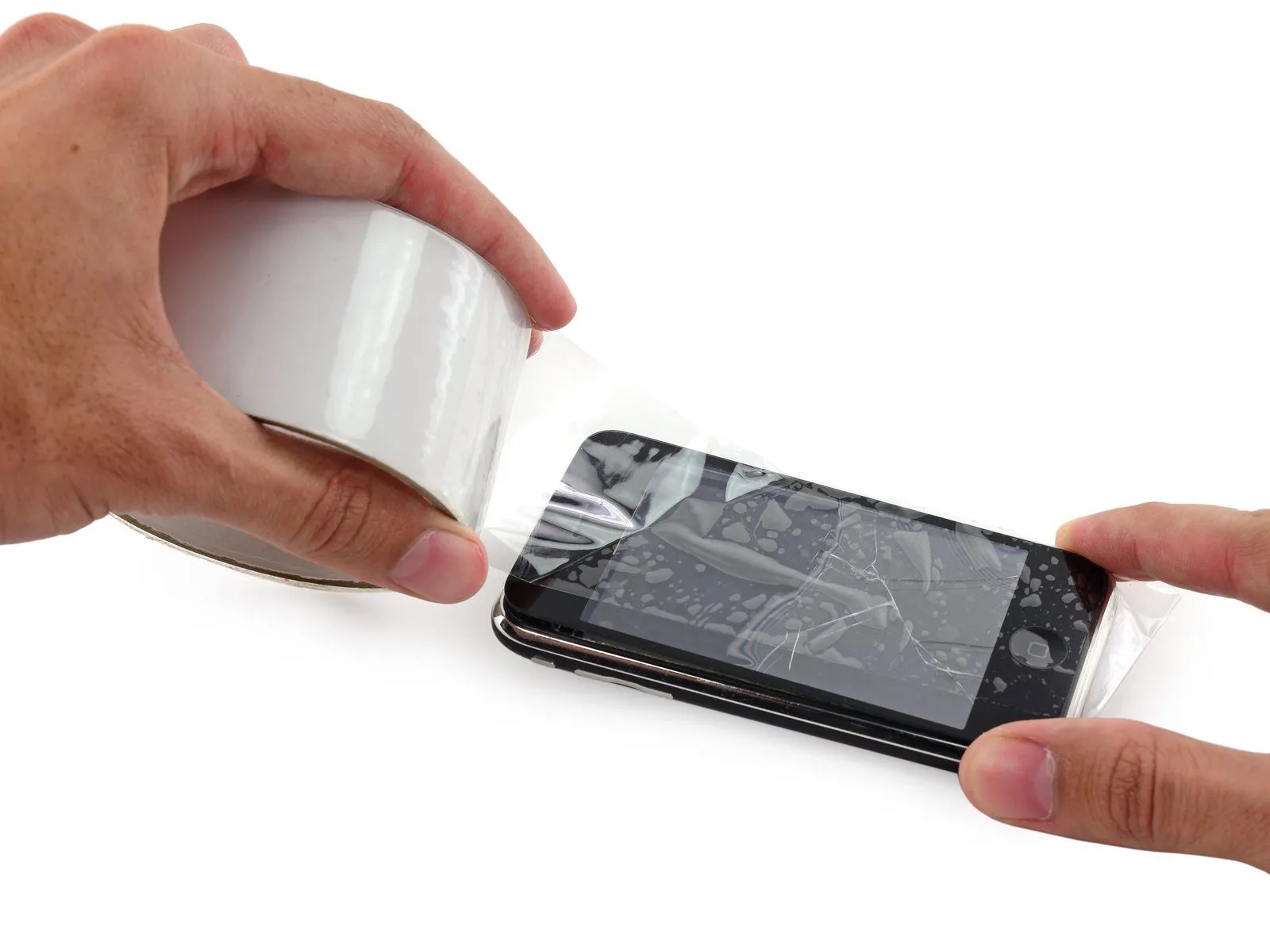
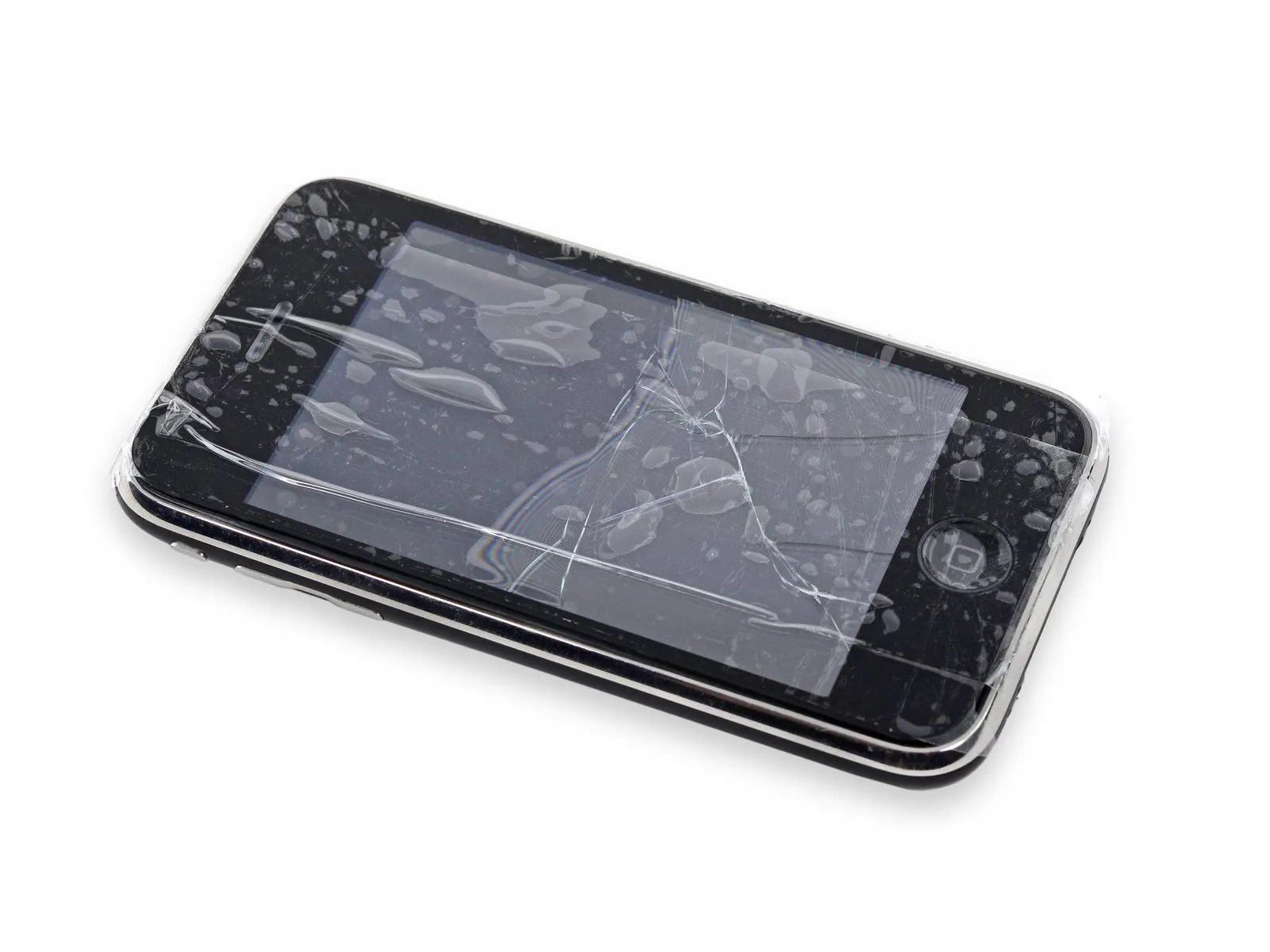
To avoid injury and contain shattered fragments while you work, secure any cracked display glass with tape.
Apply clear packing tape across the iPhone's screen surface, ensuring each strip overlaps the previous one to completely protect the display.
To prevent scattered glass fragments and maintain stability during the display separation process, this technique is essential.
To safeguard your eyes from potential glass fragments released during the repair process, always use safety glasses.
Apply clear packing tape across the iPhone's screen surface, ensuring each strip overlaps the previous one to completely protect the display.
To prevent scattered glass fragments and maintain stability during the display separation process, this technique is essential.
To safeguard your eyes from potential glass fragments released during the repair process, always use safety glasses.
Step 2 | Vibrator
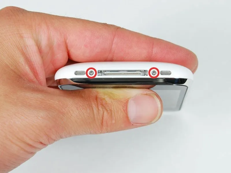
Using a Phillips #00 screwdriver, detach the two screws securing the dock connector.
Step 3
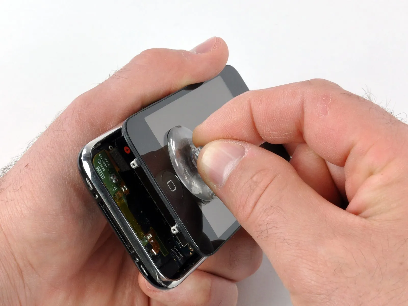
For improved handling and safety, detach the metal handle from the suction cup; gripping the suction cup's base directly simplifies this process.
Exercise extreme caution during iPhone disassembly to prevent damage to the delicate display cables.
A black display assembly is sealed to the silver front bezel by a rubber gasket, and disassembling these components necessitates applying moderate pressure.
Carefully lift the lower edge of the iPhone's display assembly by applying gentle upward force with a suction cup positioned close to the Home button.
When the display assembly's surface prevents a secure suction cup attachment due to damage, employ a robust adhesive tape, like duct tape, as an alternative.
Exercise extreme caution during iPhone disassembly to prevent damage to the delicate display cables.
A black display assembly is sealed to the silver front bezel by a rubber gasket, and disassembling these components necessitates applying moderate pressure.
Carefully lift the lower edge of the iPhone's display assembly by applying gentle upward force with a suction cup positioned close to the Home button.
When the display assembly's surface prevents a secure suction cup attachment due to damage, employ a robust adhesive tape, like duct tape, as an alternative.
Step 4
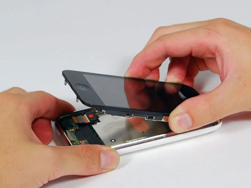
Several cables continue to secure the display assembly to the iPhone’s internal components; therefore, avoid attempting complete separation at this stage.
Tilt the display assembly upwards, achieving roughly a 45-degree angle.
Tilt the display assembly upwards, achieving roughly a 45-degree angle.
Step 5
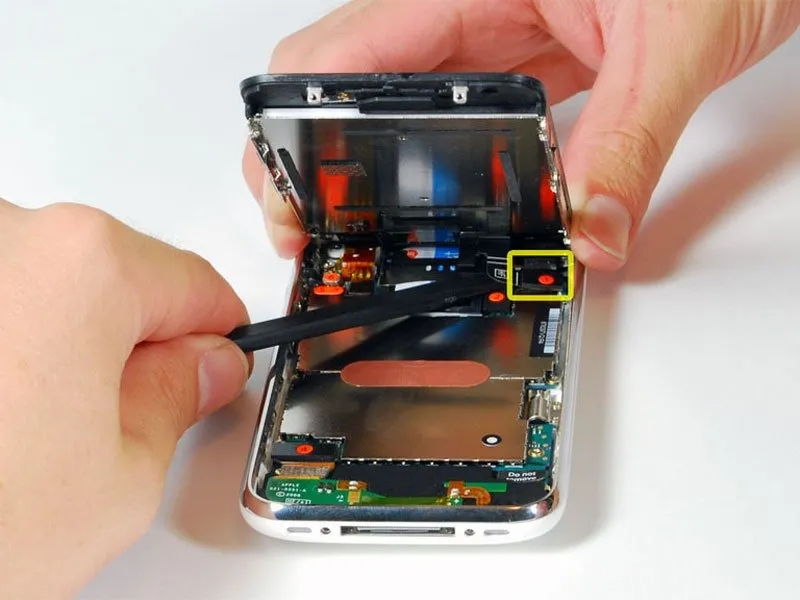
Using one hand to secure the display assembly, employ a spudger with your other hand to carefully detach the ribbon cable identified as "1."
Step 6
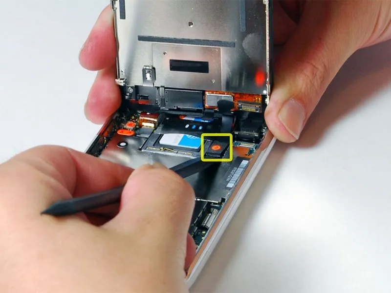
To facilitate disconnection of the remaining cables, adjust the display assembly's orientation so it is positioned nearly perpendicular to its base.
Carefully detach the ribbon cable identified with the "2" label using a spudger.
Carefully detach the ribbon cable identified with the "2" label using a spudger.
Step 7
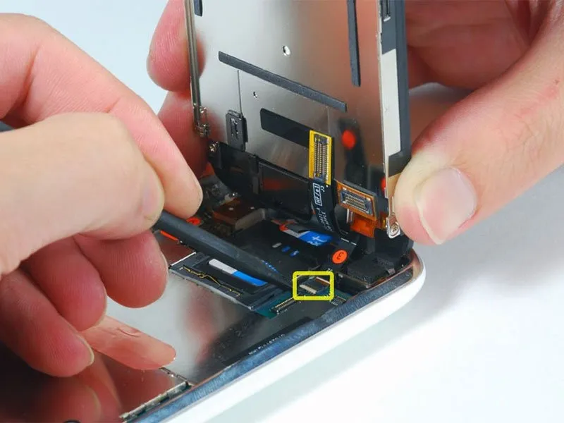
Employ a spudger to lift the 90-degree rotating white plastic hinge, which secures the remaining ribbon cable. This action will disengage the cable.
Identify the flap, which will be either black or white, and raise the hinged portion; avoid lifting the socket.
Carefully disconnect the black ribbon cable by sliding it from its connector, then detach the display assembly from the iPhone.
Identify the flap, which will be either black or white, and raise the hinged portion; avoid lifting the socket.
Carefully disconnect the black ribbon cable by sliding it from its connector, then detach the display assembly from the iPhone.
Step 8
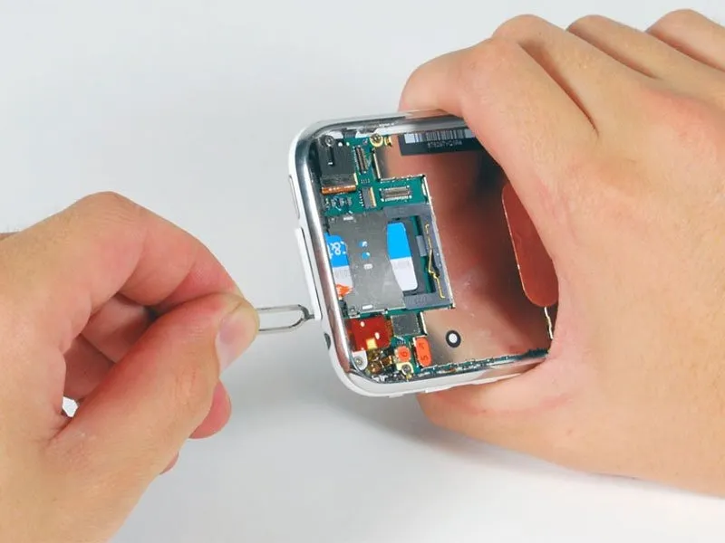
Using a SIM eject tool or a straightened paper clip, gently push into the small aperture located adjacent to the headphone jack.
Apply pressure to the tool, ensuring it remains aligned, until the SIM card tray ejects.
Using a firm grip, extract the SIM card tray from the iPhone by sliding it outward.
Apply pressure to the tool, ensuring it remains aligned, until the SIM card tray ejects.
Using a firm grip, extract the SIM card tray from the iPhone by sliding it outward.
Step 9
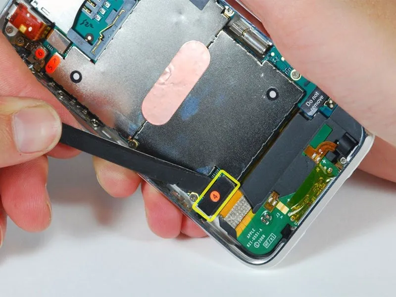
Carefully detach the ribbon cable identified as "4" using a spudger.
Step 10
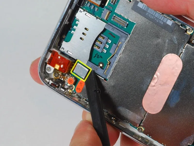
Carefully detach the ribbon cable identified as "5" using a spudger.
Step 11
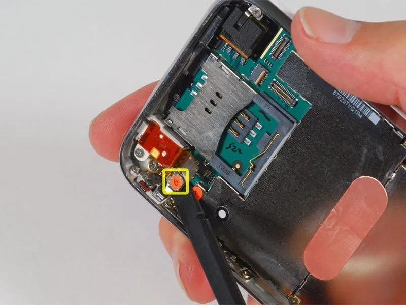
Carefully detach the ribbon cable identified as "6" using a spudger.
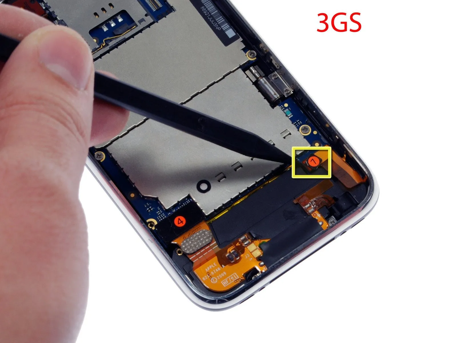
For iPhone 3GS models, consult image 2 and employ a spudger to release the ribbon cable identified as "7."
For iPhone 3GS models, consult image 2 and employ a spudger to release the ribbon cable identified as "7."
Step 12
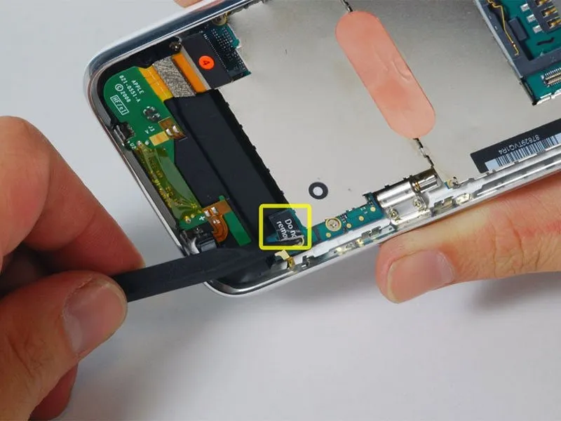
Exercise caution while separating the adhesive backing from the label that bears the warning "Do not remove."
Step 13
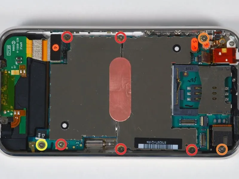
Detach the component by unscrewing eight fasteners.
The logic board is affixed to the rear panel using five screws; each is 2.3 mm in length, features a Phillips #00 head, and has partial threads.
The logic board and camera are fastened together using two screws; each is a full-thread Phillips #00 screw, measuring 2.3 mm in diameter.
Locate the "Do not remove" sticker and, underneath it, you'll find a 2.9 mm Phillips #00 screw.
The logic board is affixed to the rear panel using five screws; each is 2.3 mm in length, features a Phillips #00 head, and has partial threads.
The logic board and camera are fastened together using two screws; each is a full-thread Phillips #00 screw, measuring 2.3 mm in diameter.
Locate the "Do not remove" sticker and, underneath it, you'll find a 2.9 mm Phillips #00 screw.
Step 14
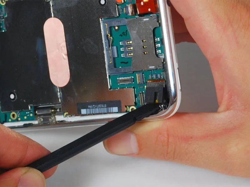
Carefully detach the camera retaining clip—previously held in place by the screw you already removed—using a spudger, then gently lift the camera module vertically from its position within the rear panel; note that the camera remains connected to the logic board at the bottom and cannot be fully disengaged at this stage.
Step 15
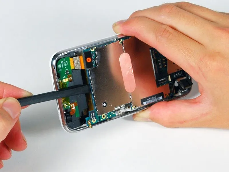
Carefully lift the logic board's edge, near the dock connector, using a spudger to avoid damage.
Verify that each of the screws holding the logic board in place has been completely unscrewed if you encounter difficulty raising the board.
Verify that each of the screws holding the logic board in place has been completely unscrewed if you encounter difficulty raising the board.
Step 16
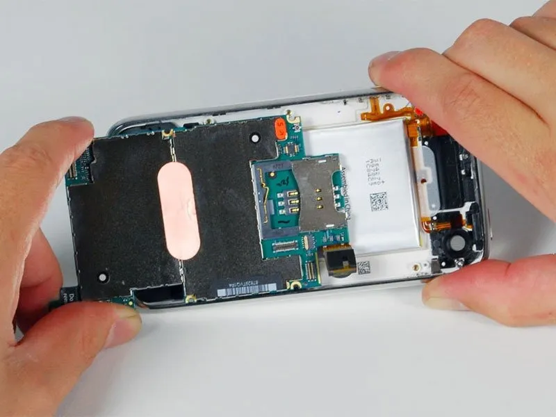
Carefully advance the logic board in the direction of the dock connector to disengage it from the iPhone's chassis.
Step 17
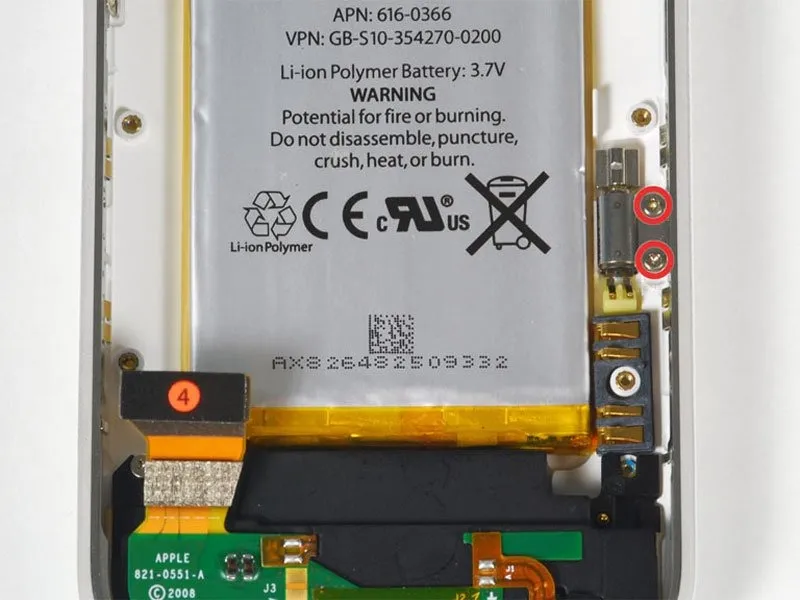
Detach the vibrator from the back panel by unscrewing the two Phillips head screws, size #00.
Due to their reduced diameter, these screws are distinct from all others; avoid confusion during disassembly and reassembly, as they are the only fasteners compatible with their designated locations.
Due to their reduced diameter, these screws are distinct from all others; avoid confusion during disassembly and reassembly, as they are the only fasteners compatible with their designated locations.
Step 18

Carefully raise the vibrator, disengaging it from its housing, to remove it from the iPhone.