iPhone 5 SIM Eject Lever Replacement
If the SIM card is experiencing difficulty being ejected from your iPhone 5, this guide details the process of either replacing or repositioning the SIM eject lever, which may be malfunctioning.
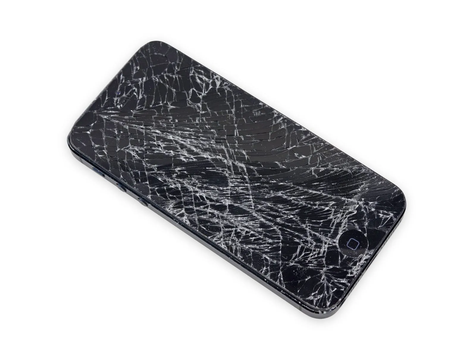
Step 1 | Taping the display glass

Begin by disconnecting the power supply, ensuring it's unplugged from the outlet, then carefully remove the 10mm retaining screw securing the fan motor to the chassis, and gently detach the fan assembly.
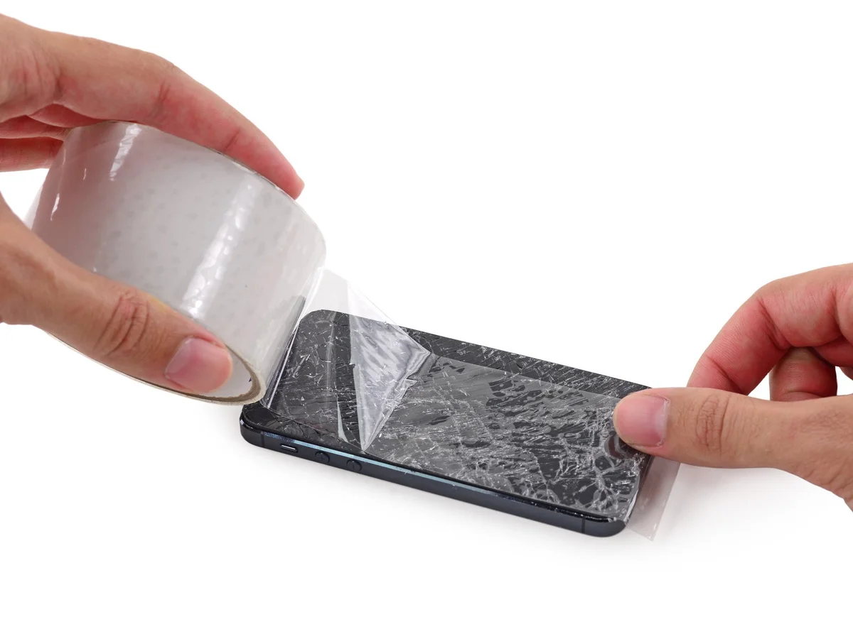
To mitigate the risk of additional shattering and potential injury while repairing a cracked display glass, secure the glass with tape.
Apply strips of transparent packing tape across the iPhone screen, ensuring complete coverage by layering them until the entire display surface is protected.
To safeguard your eyes from potential glass fragments released during the repair process, always use safety glasses.
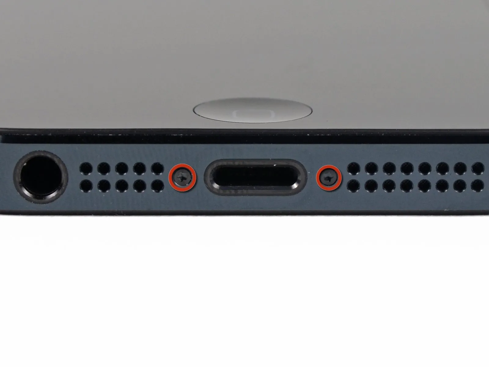
Step 2 | Remove the Pentalobe screws
Using a 5/32-inch hex key, carefully loosen the four screws securing the fan assembly to the motor housing; observe that these screws are tightened to a torque of 6 in-lbs, and ensure you do not overtighten them during reassembly to prevent damage.
To prevent a potential fire or explosion hazard during repair, ensure the iPhone's lithium-ion battery is depleted to less than 25% capacity prior to beginning work; a fully charged battery poses a risk of ignition if damaged.
To prevent electrical shock or damage, ensure the iPhone is completely de-energized prior to starting the repair process.
Using a Pentalobe screwdriver, detach the two screws measuring 3.6 mm located adjacent to the Lightning connector.
Step 3 | How to prevent display separation


Using a 5/32-inch hex key, carefully tighten the four mounting screws securing the fan assembly to the motor housing, ensuring they are snug but not over-tightened to avoid damaging the plastic threads; observe torque specifications of 4 in-lbs per screw.
Carefully separate the display assembly, which consists of a glass screen, a plastic bezel, and metal clips, from the phone's main body during the subsequent procedures.
Ensure complete removal of the display assembly, irrespective of the chosen tool.
When separation between the glass and plastic is observed, similar to the depiction in the initial image, use a plastic opening tool to insert it into the space between the plastic frame and the phone's metal chassis, carefully releasing the metal clips from their housings.
To ensure proper closure during reassembly of a phone featuring a detached display bezel, apply a narrow adhesive strip positioned between the plastic bezel and the glass surface.
Step 4 | Anti-Clamp instructions


Using a 5/32-inch hex key, carefully tighten the three retaining screws securing the fan motor to the blower housing, ensuring each is snug but not over-tightened to prevent damage; observe torque specifications of 3.5 inch-pounds per screw.
To simplify the opening process, the following two steps utilize the Anti-Clamp tool; if you do not have this tool, proceed two steps further to find an alternative procedure.
Refer to the accompanying guide for detailed procedures regarding Anti-Clamp operation.
To release the Anti-Clamp's arms, move the blue handle in a rearward direction.
Position the arms so they clear the left or right side of the iPhone and then move them into place.
Securely attach two suction cups, one to the front and one to the rear surface of the iPhone, placing them close to the lower edge and directly above the home button.
Apply vacuum by pressing the cups firmly against the surface needing treatment.
To enhance the Anti-Clamp's grip if the iPhone's exterior feels excessively smooth, apply adhesive tape to the device's surface.
Step 5


Using a 5/32-inch hex key, carefully tighten the three retaining screws on the motor assembly to a torque of 3.5 inch-pounds, ensuring not to overtighten and potentially damage the threads.
To secure the arms, advance the blue handle in the direction indicated.
Rotate the handle fully, completing a 360-degree turn, observing for the initial signs of cup expansion.
Maintain parallel positioning of the suction cups; should misalignment occur, gently release the suction cups' grip and reposition the arms.
Once sufficient space is created by the Anti-Clamp, slide a prying tool beneath the display.
To ensure adequate separation, increase the heat applied to the component and then rotate the handle 90 degrees.
Allow the Anti-Clamp device to function for a full minute after each adjustment, and limit each tightening increment to no more than 90 degrees.
Step 6 | Manual Opening Procedure
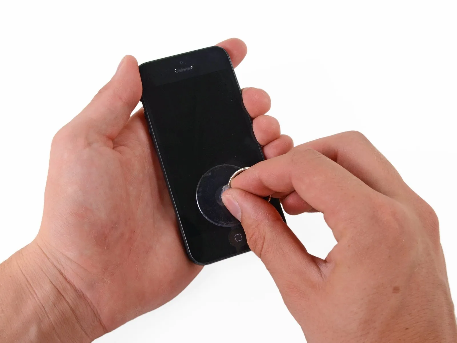
Position a suction cup directly on the display surface, located immediately above the home button.
Ensure the screen's entire surface is covered by the cup to guarantee a secure connection.
To prevent shattered glass fragments from scattering and to provide a secure attachment point for the suction cup, apply several strips of packing tape to the cracked display, carefully smoothing them to eliminate air pockets.
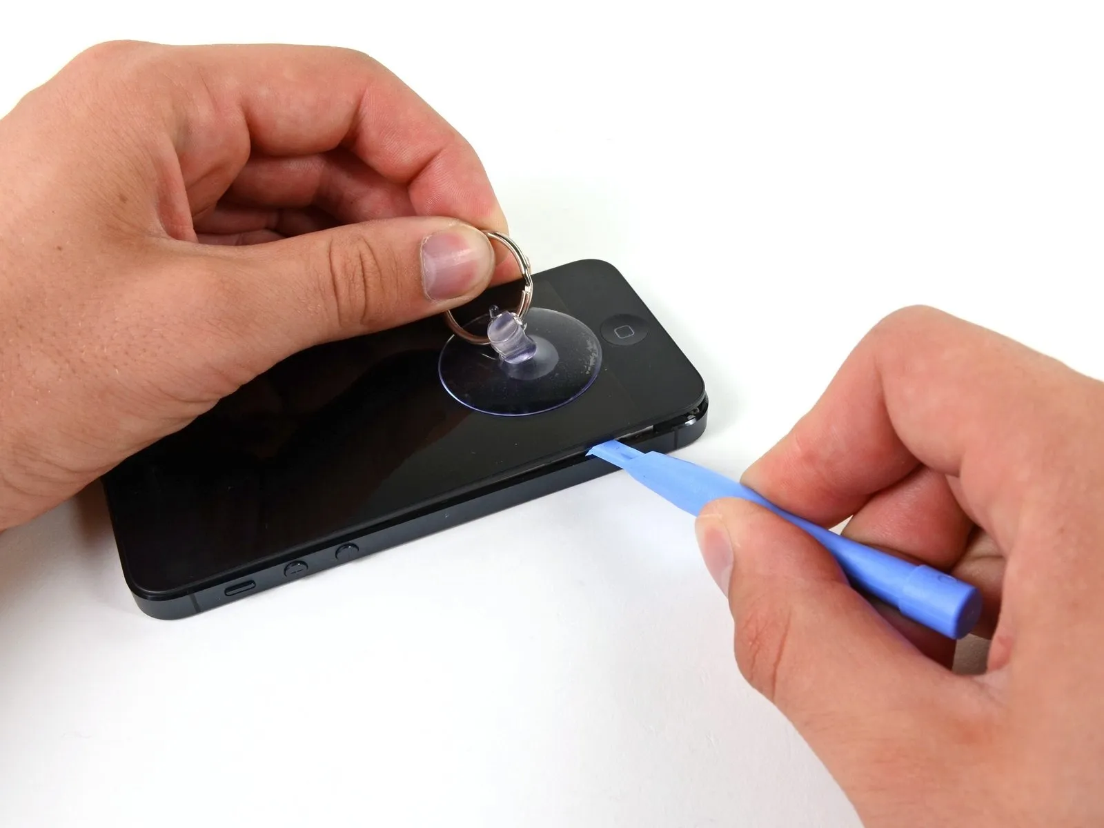
Step 7 | Start lifting the front panel assembly
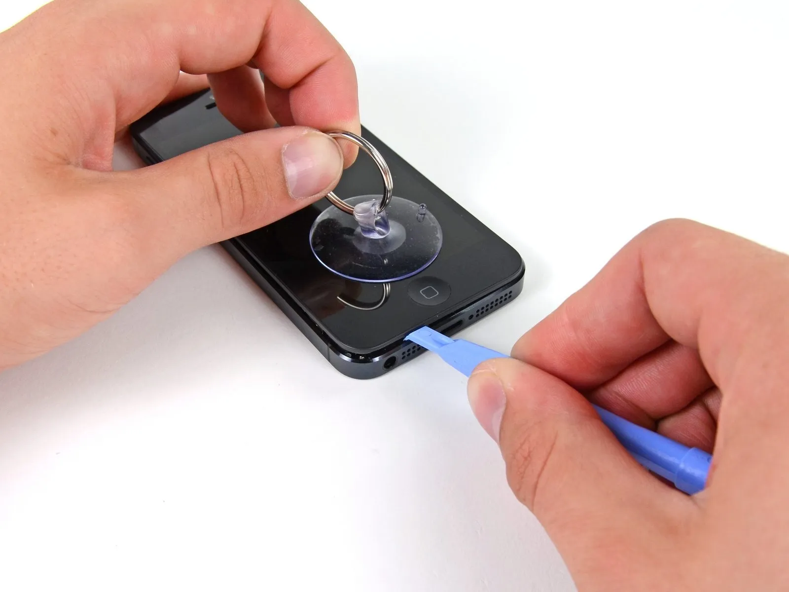
Secure the front panel assembly to the suction cup, ensuring a strong and stable connection.
Using one hand to secure the iPhone, gently lift the suction cup to create a small gap between the front panel and the rear enclosure.
Exercise caution and use steady, even pressure during installation, as the display assembly exhibits a significantly snugger fit compared to typical device components.
Using a plastic opening tool, apply gentle upward pressure while separating the rear case from the display assembly, assisted by the suction cup.
To release the front panel assembly from the rear case, carefully disengage the multiple retaining clips, potentially requiring the coordinated use of both a suction cup and a plastic opening tool.
Step 8 | Detaching the front panel side clips
Carefully separate the front panel assembly from the chassis by releasing the retaining clips located on both the left and right edges, using prying action.
Step 9 | Opening up the phone
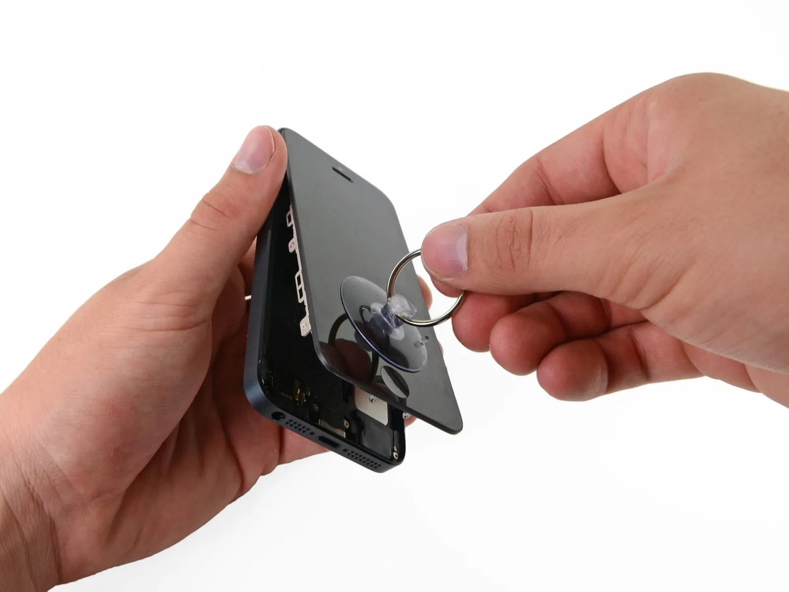

Disconnecting the front panel assembly from the rear case is not recommended; several ribbon cables remain connected at the top of the iPhone and attempting full separation will likely damage them.
After disengaging the retaining clips located along the lower edge and both sides of the front panel assembly, separate the assembly's lower section from the rear case by applying gentle pulling force.
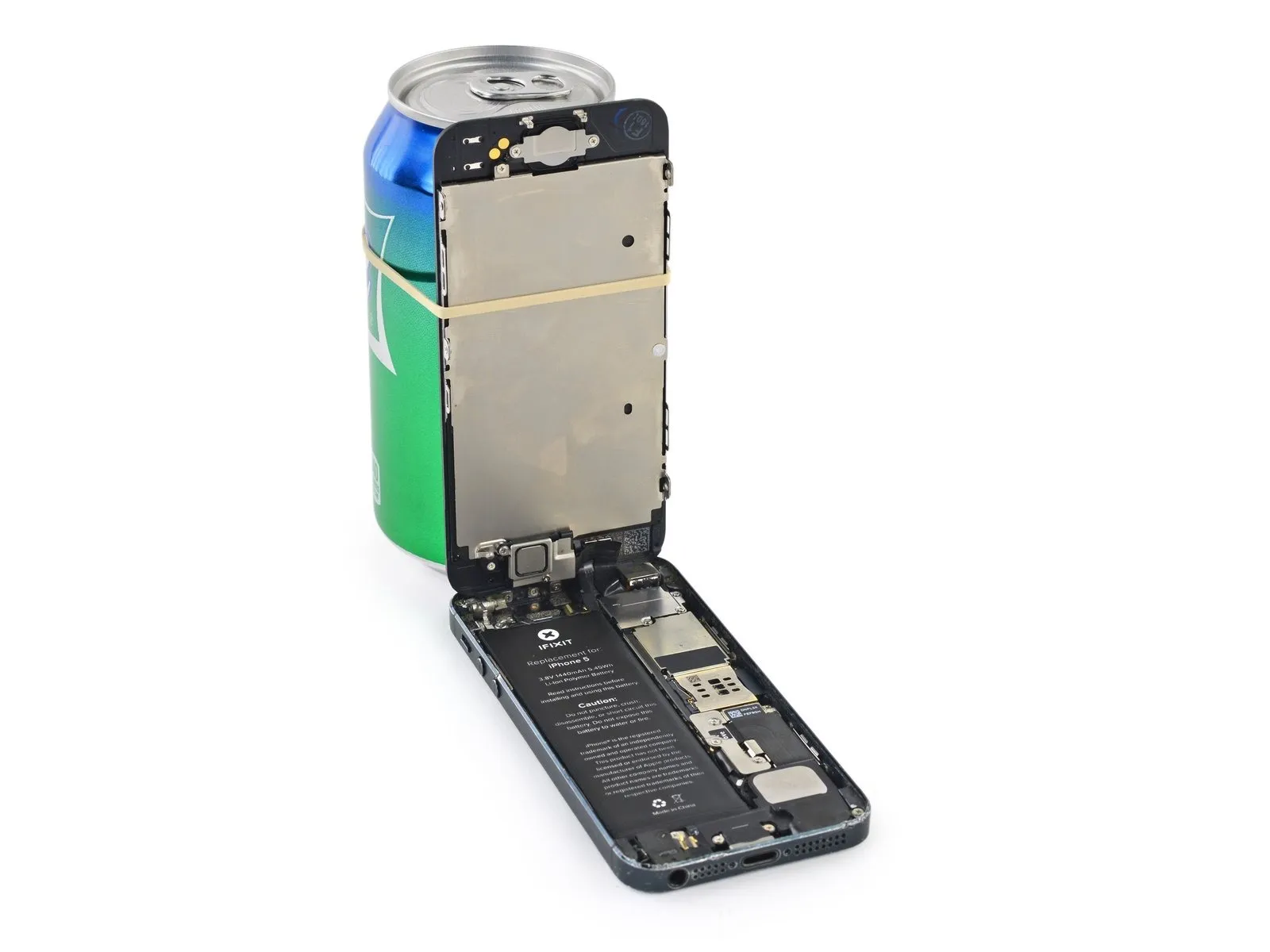
Carefully position the display at a 90-degree angle, then secure it in an upright position using a support to prevent movement during the repair process.
To avoid stressing the display's wiring during the repair process, secure it with a rubber band.
After disengaging the retaining clips located along the lower edge and both sides of the front panel assembly, separate the assembly's lower section from the rear case by applying gentle pulling force.
Carefully position the display at a 90-degree angle, then secure it in an upright position using a support to prevent movement during the repair process.
To avoid stressing the display's wiring during the repair process, secure it with a rubber band.
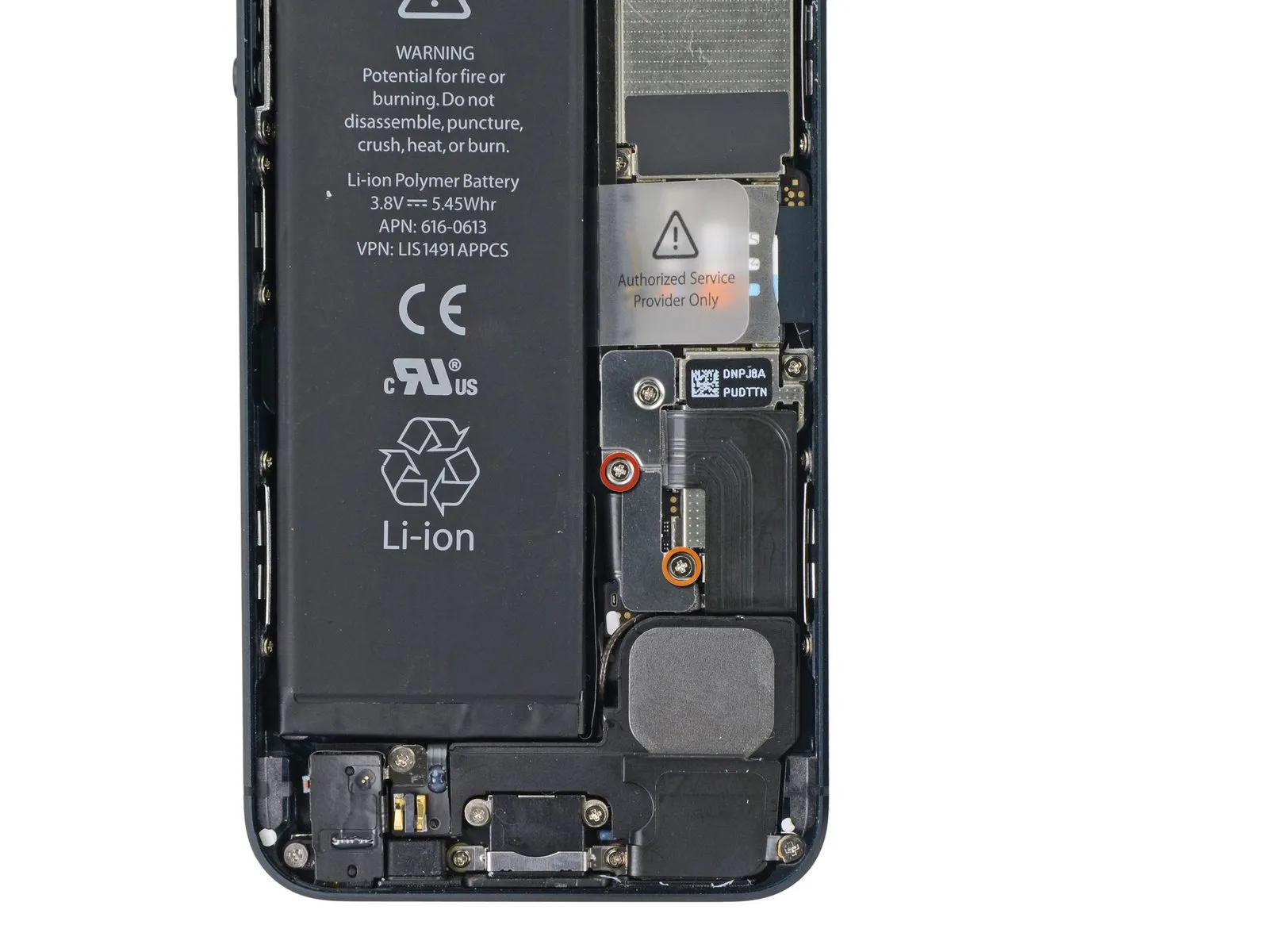
Step 10 | Removing the battery connector bracket screws
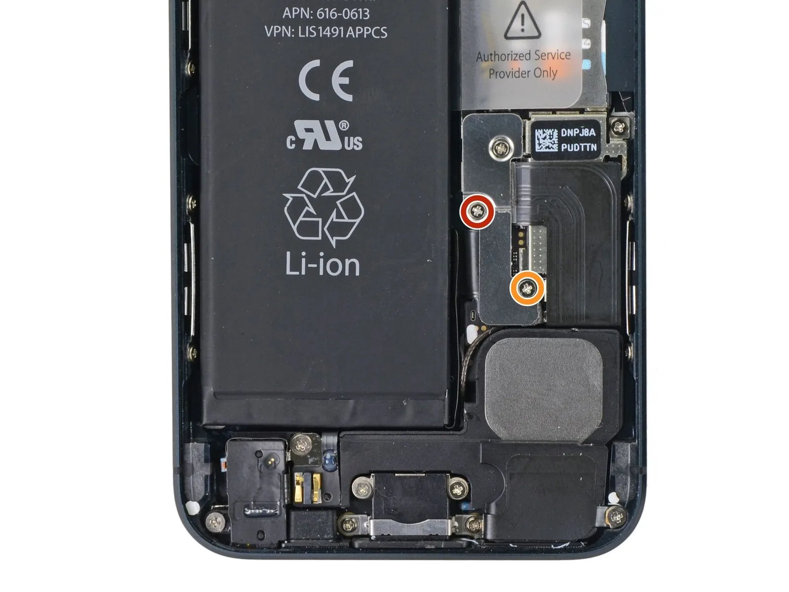
Using appropriate tools, detach the two screws that fasten the metal battery connector bracket to the logic board.
Use a Phillips screwdriver to remove a single screw with a 1.8 mm head.
Use a Phillips screwdriver to remove a single screw with a 1.6 mm head.
Use a Phillips screwdriver to remove a single screw with a 1.8 mm head.
Use a Phillips screwdriver to remove a single screw with a 1.6 mm head.
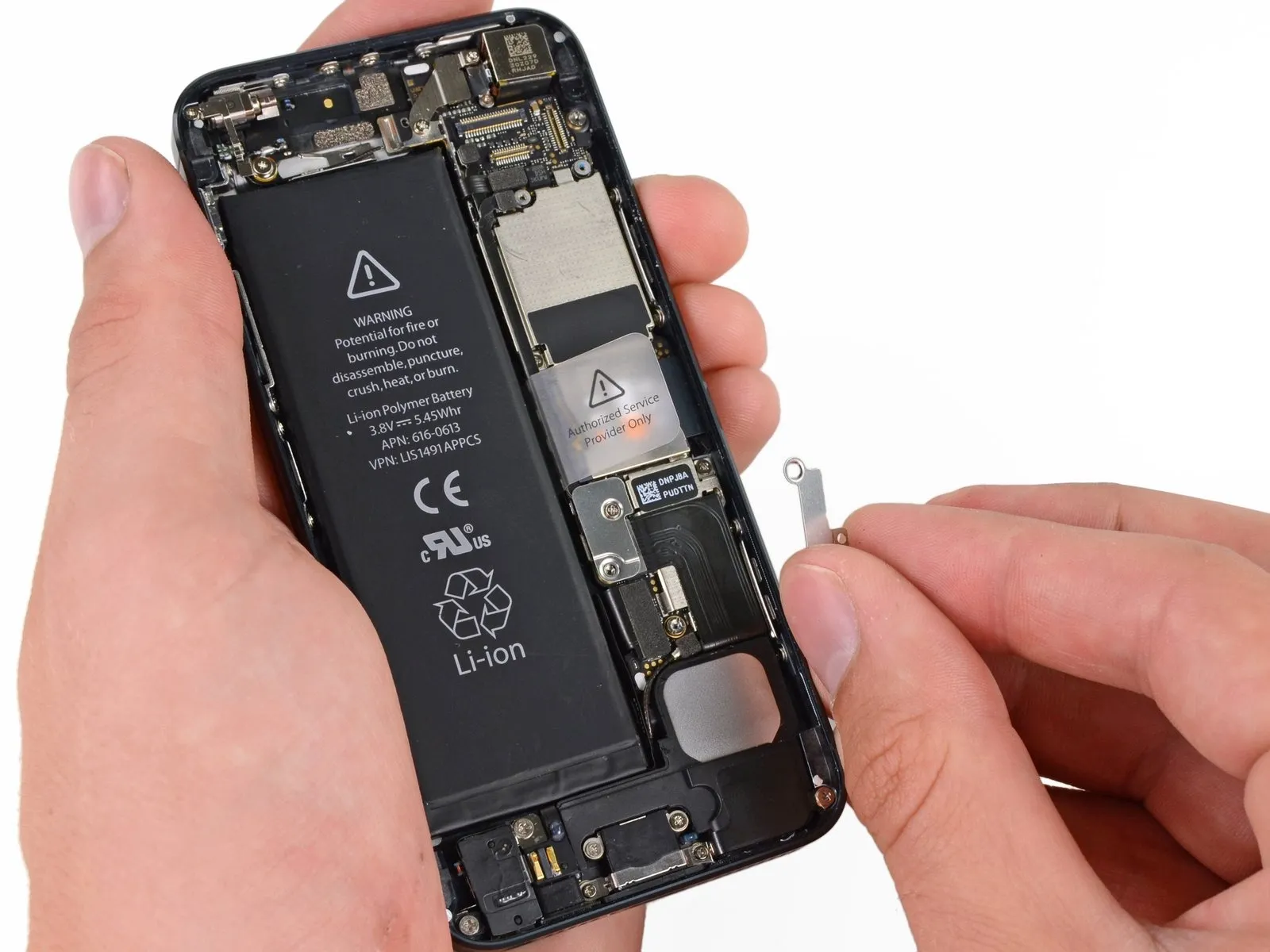
Step 11 | Removing the battery connector bracket
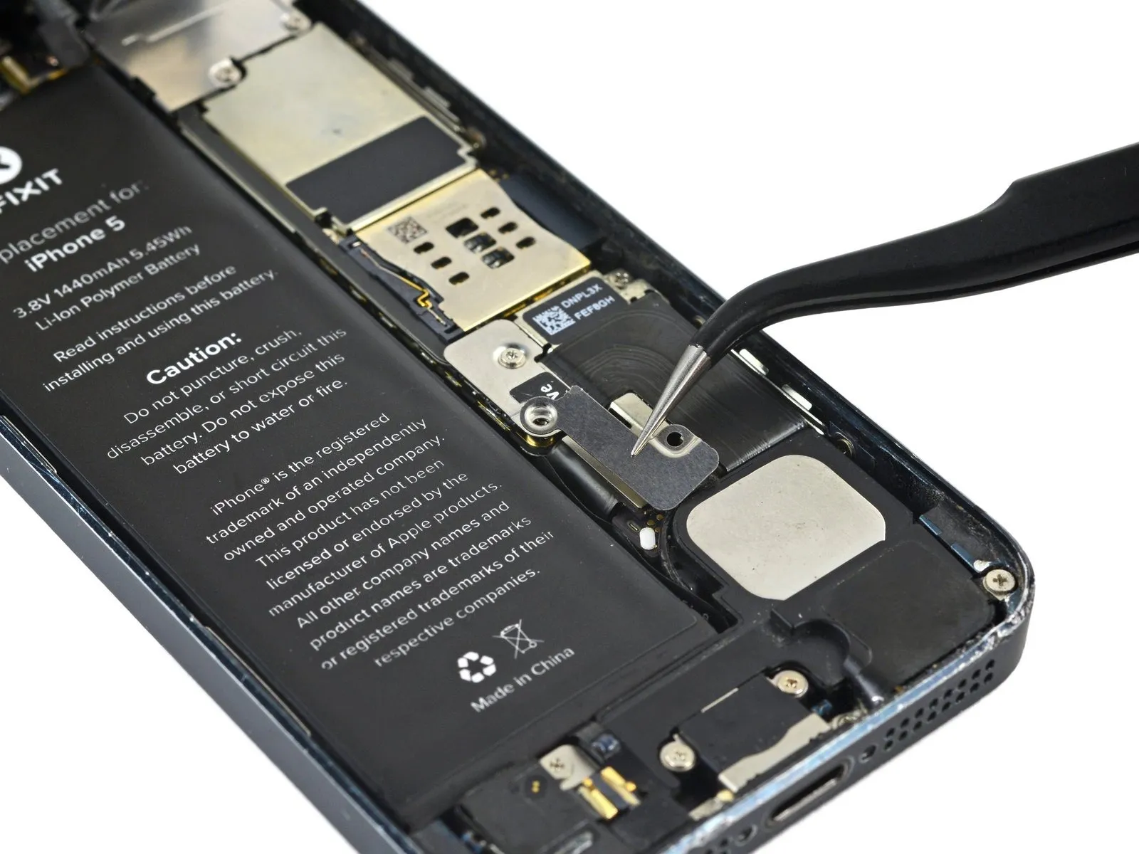
Using a precision screwdriver, detach the bracket securing the battery connector.
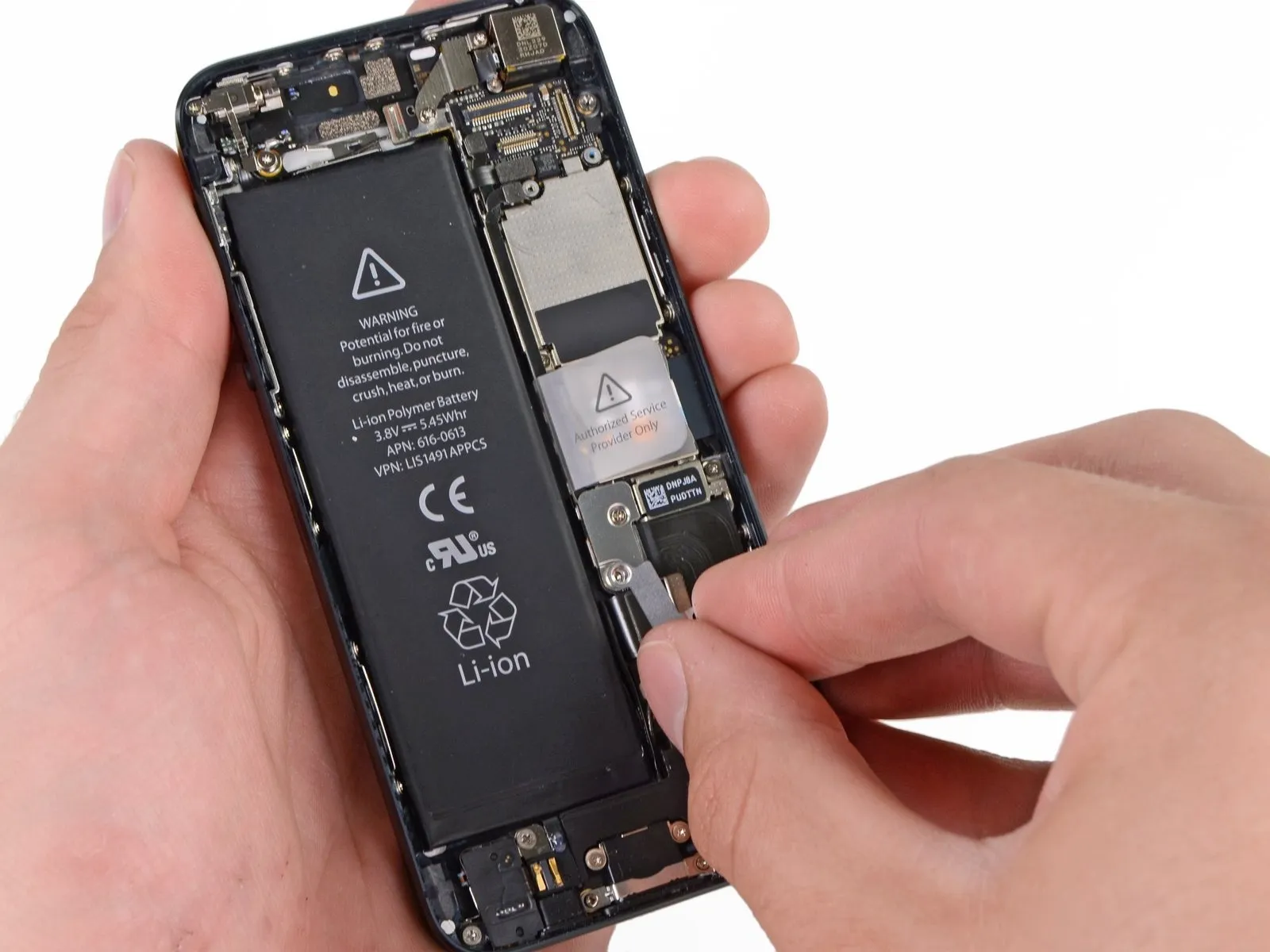
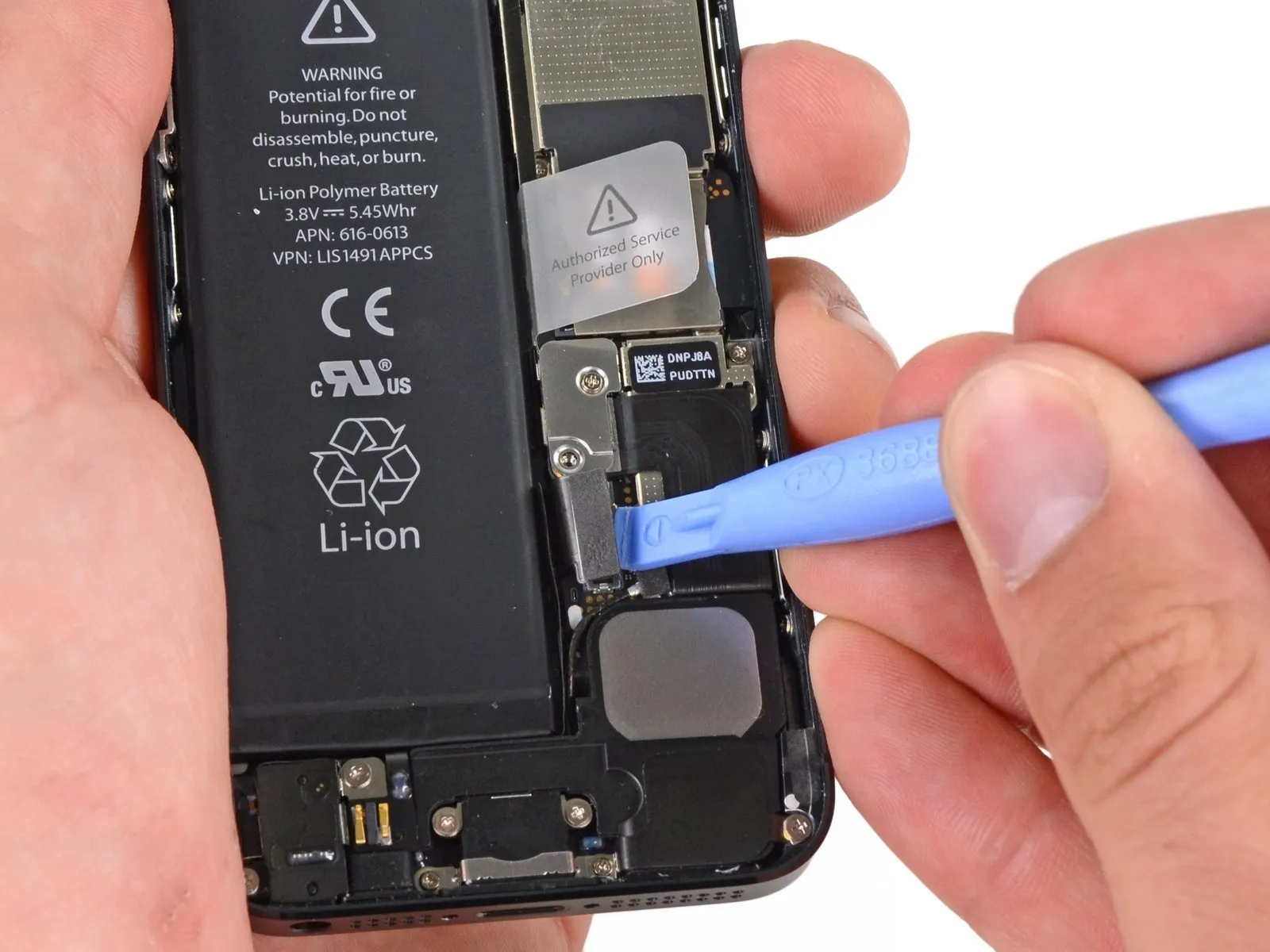
Step 12 | Disconnecting the battery connector
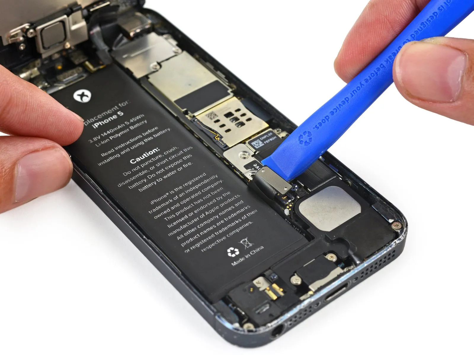
Carefully lift the battery connector away from its connection on the logic board using a plastic opening tool, ensuring no force is applied.
Exercise caution to avoid disturbing the tiny components positioned near the socket.
Exercise extreme caution when releasing the battery connector, ensuring force is applied solely to the connector and not the logic board socket; applying pressure to the socket or the board could result in socket destruction or damage to adjacent components.
Step 13 | Removing the front panel assembly cable bracket screws
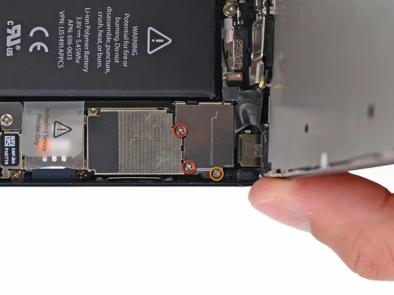
Detach the cable bracket that holds the front panel assembly wires from the logic board by unscrewing the screws listed below.
Use two screws, each with a 1.2 mm Phillips head.
Use a Phillips screwdriver to remove a single screw with a 1.6 mm head.
Because this fastener lacks magnetic properties, use caution to prevent it from falling during removal, and ensure it's correctly positioned afterward; a magnetized replacement could disrupt the compass's functionality.
Step 14 | Removing the front panel assembly cable bracket

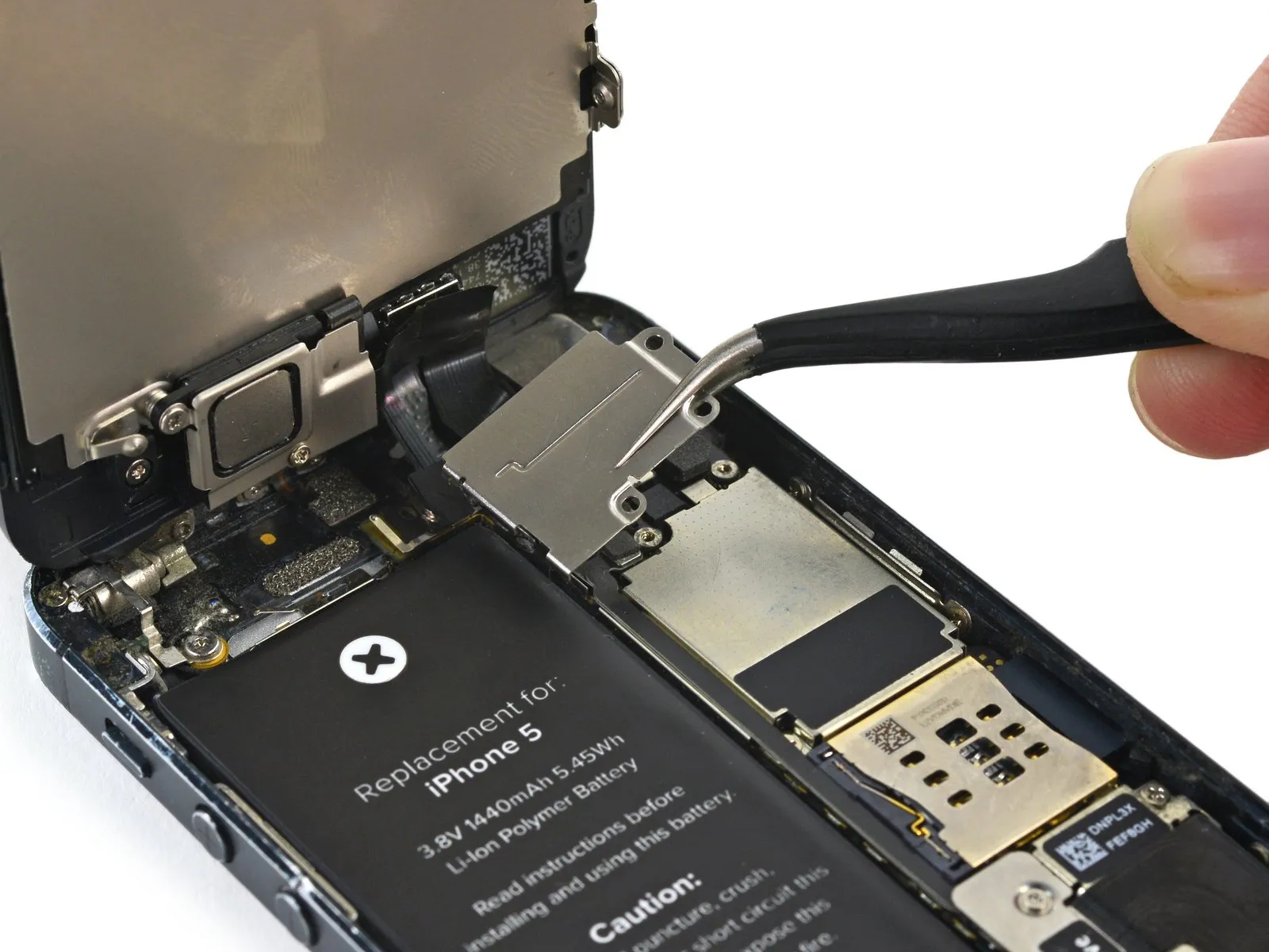
To detach the display cable bracket, raise it in the direction of the battery, then take it out of the iPhone.
To reassemble, secure the left-hand hooks to the logic board, then move the bracket outward.
To reassemble, secure the left-hand hooks to the logic board, then move the bracket outward.
Step 15 | Disconnecting the front panel assembly cables

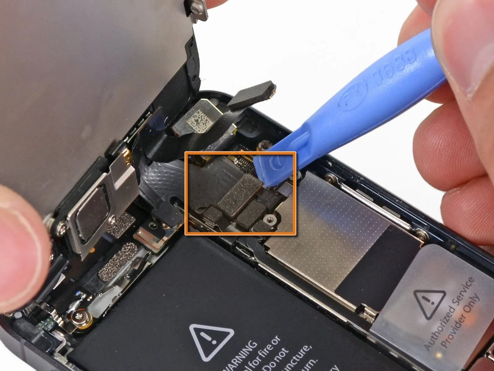
Prior to either detaching or reattaching the cables detailed in this procedure, ensure the battery is completely disconnected.
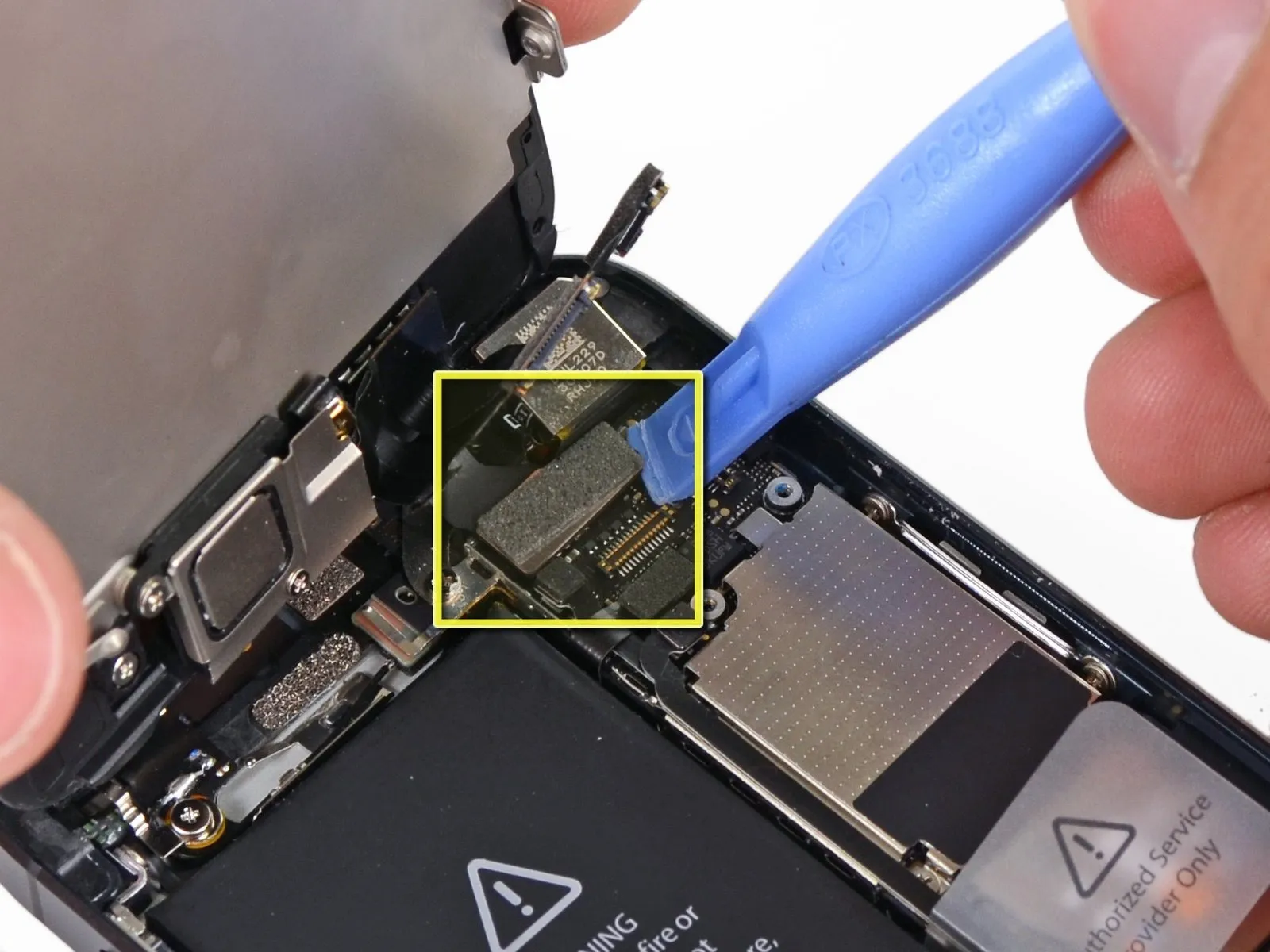
Carefully detach the three front panel assembly cables by gently separating them using a plastic opening tool or your fingernail.
The cable connecting the front camera and its associated sensor.
Connect the display panel's flat, ribbon-like cable, ensuring proper alignment to the corresponding connector pins, and secure it with the specified pressure using a calibrated tool to prevent damage; refer to the service manual for precise connector location and pressure specifications.
The flexible circuit board connecting the touchscreen to the device's logic board.
Should the LCD cable become detached from its connector during reassembly, it may result in display abnormalities, such as white lines or a complete lack of image when the device is turned on; to resolve this, reattach the cable and restart the phone by disconnecting and reconnecting the battery.
Step 16 | Separating front panel assembly and rear case
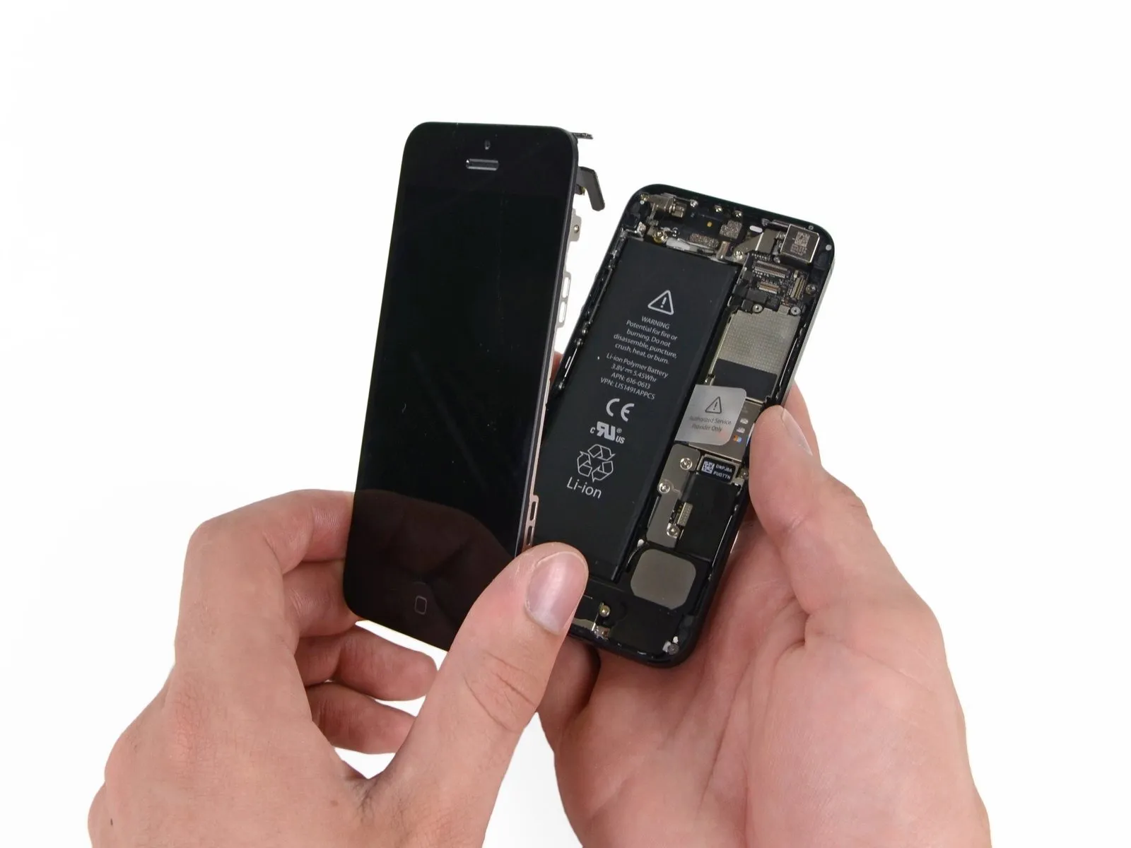
Detach the front panel assembly by disengaging it from the rear case.
Step 17 | Battery Connection
Using a Phillips screwdriver, detach the metal battery connector bracket from the logic board by unscrewing a 1.8 mm Phillips screw and a 1.6 mm Phillips screw.
Step 18
Using a precision screwdriver, detach the metal bracket that holds the battery connector in place on the iPhone.
Step 19

Carefully lift the battery connector away from its corresponding socket on the logic board using a plastic opening tool, ensuring that force is applied solely to the connector itself to avoid damaging the socket, as applying pressure to the socket could result in its breakage.
Step 20 | SIM Card
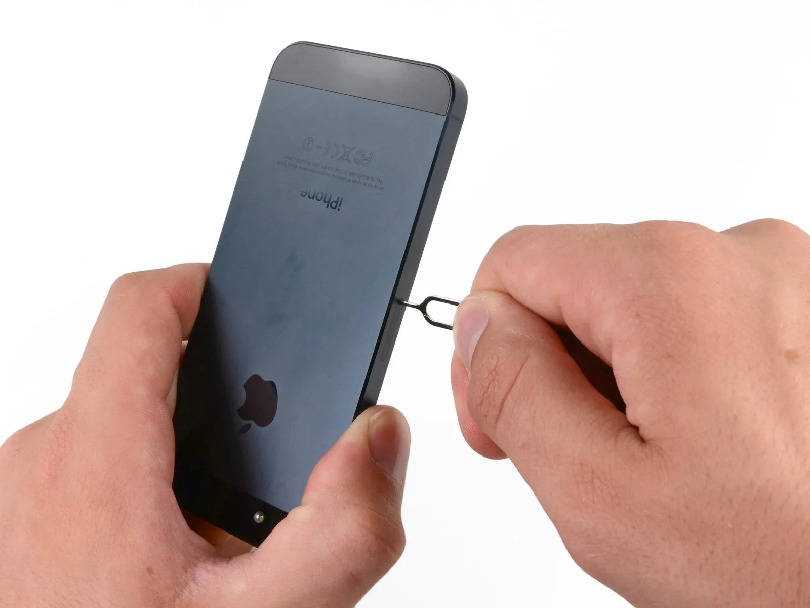
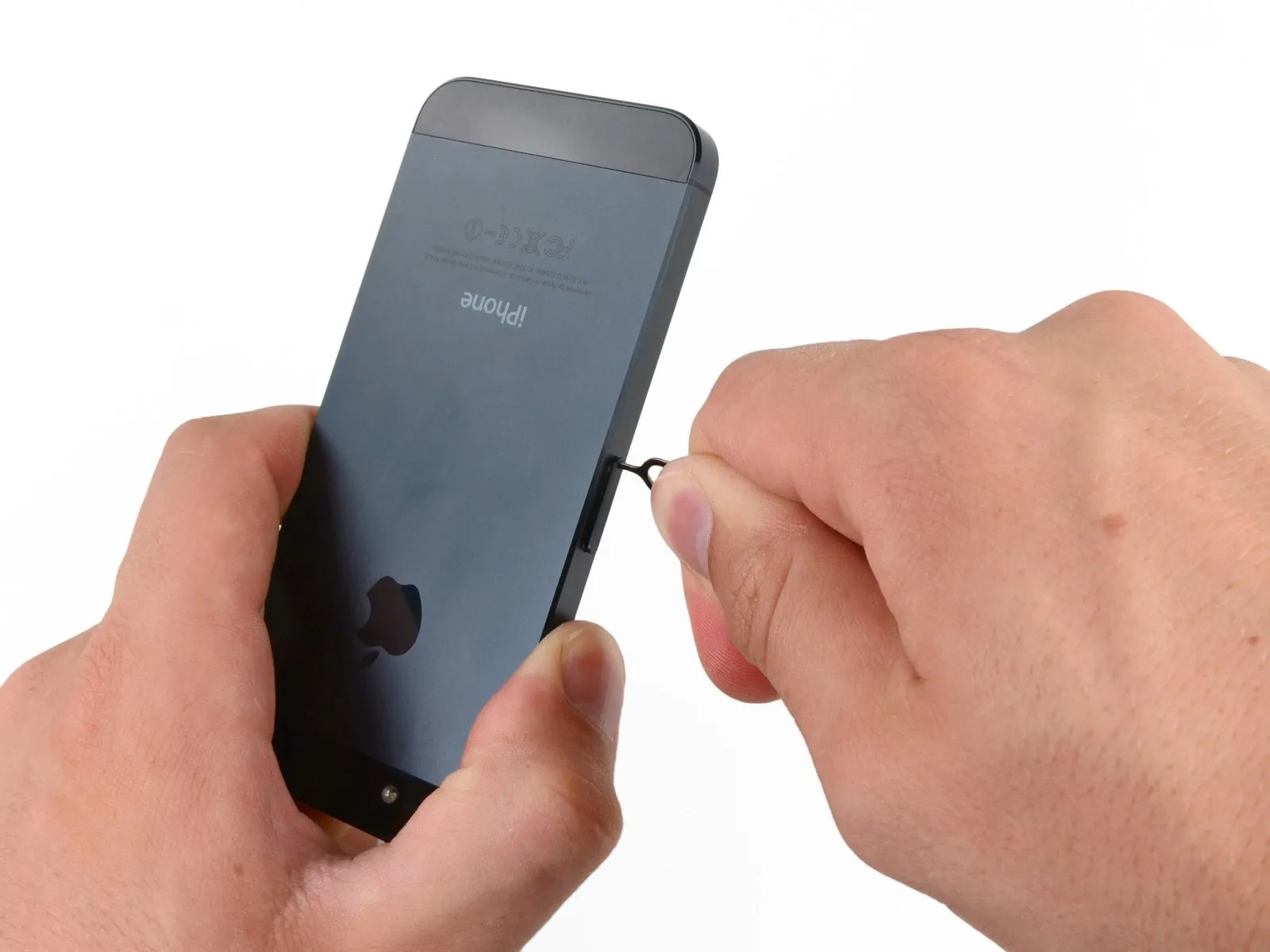
Employing a SIM card eject tool or a straightened paperclip, release the SIM card and its corresponding tray.
Step 21
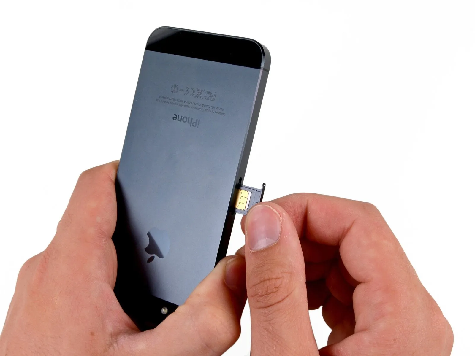
Using the SIM ejection tool or a similar small, sturdy item, carefully depress the SIM tray release mechanism located on the device's left side to extract the SIM Card tray assembly.
Step 22 | SIM Eject Lever
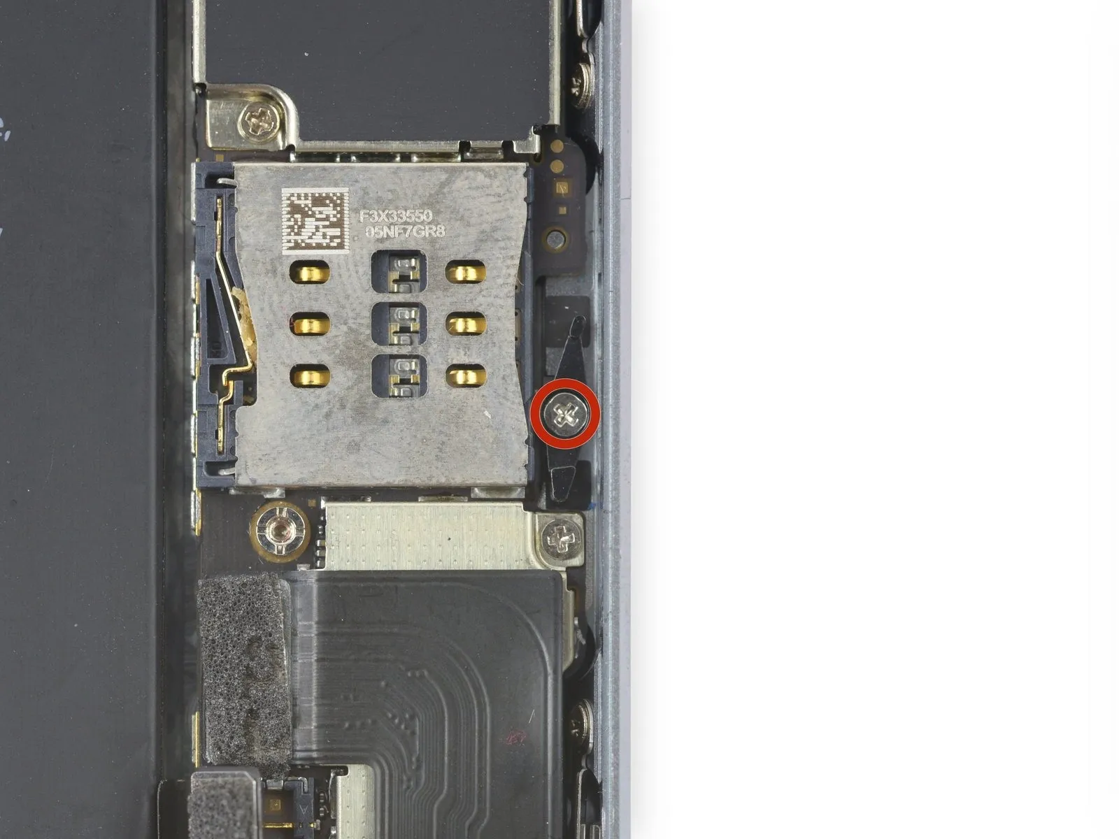
Using a Phillips #00 screwdriver, detach the SIM eject lever by removing the 2.1 mm screw that holds it in place.
Step 23
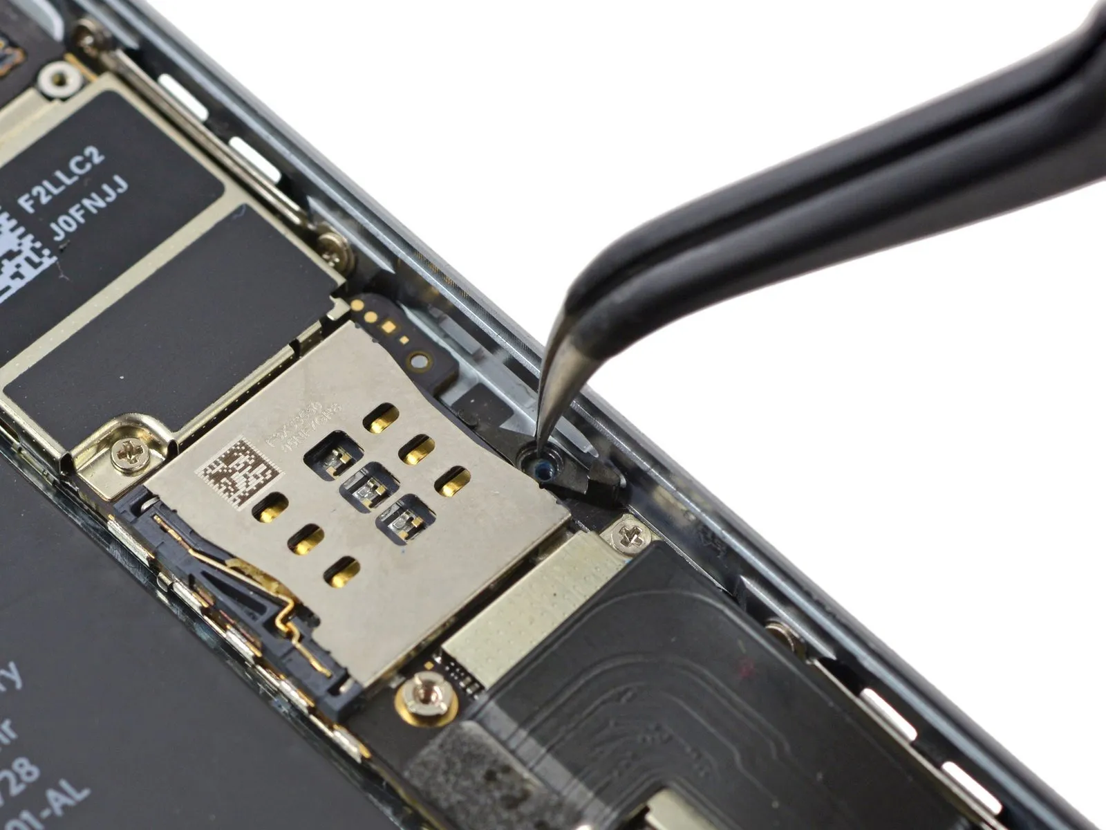
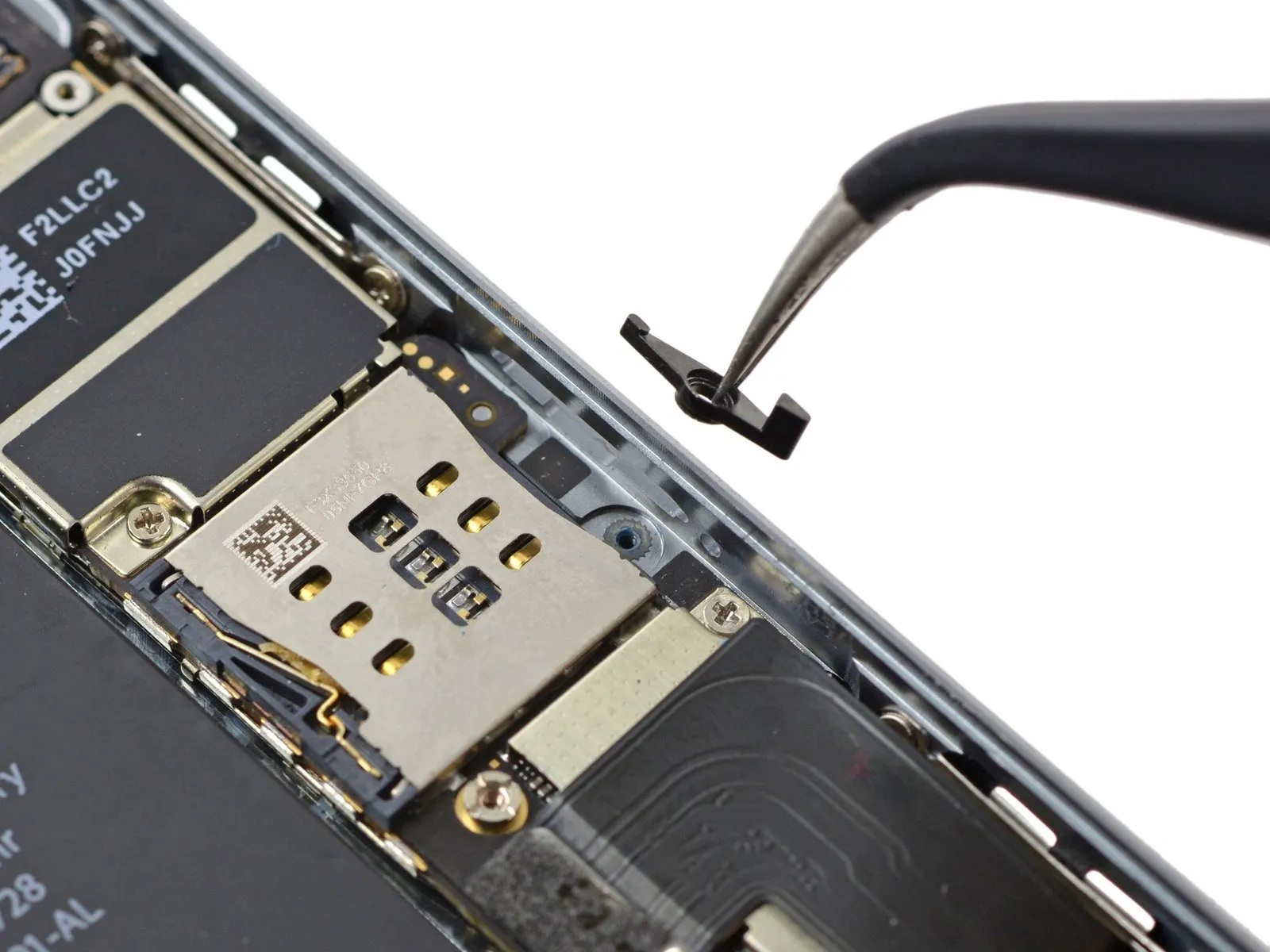
Using a compatible tool, carefully extract the SIM eject lever from the iPhone.
Ensure correct placement during reassembly, aligning the component's broader extremity with the SIM card release aperture.
Ensure correct placement during reassembly, aligning the component's broader extremity with the SIM card release aperture.