iPhone 5 Teardown
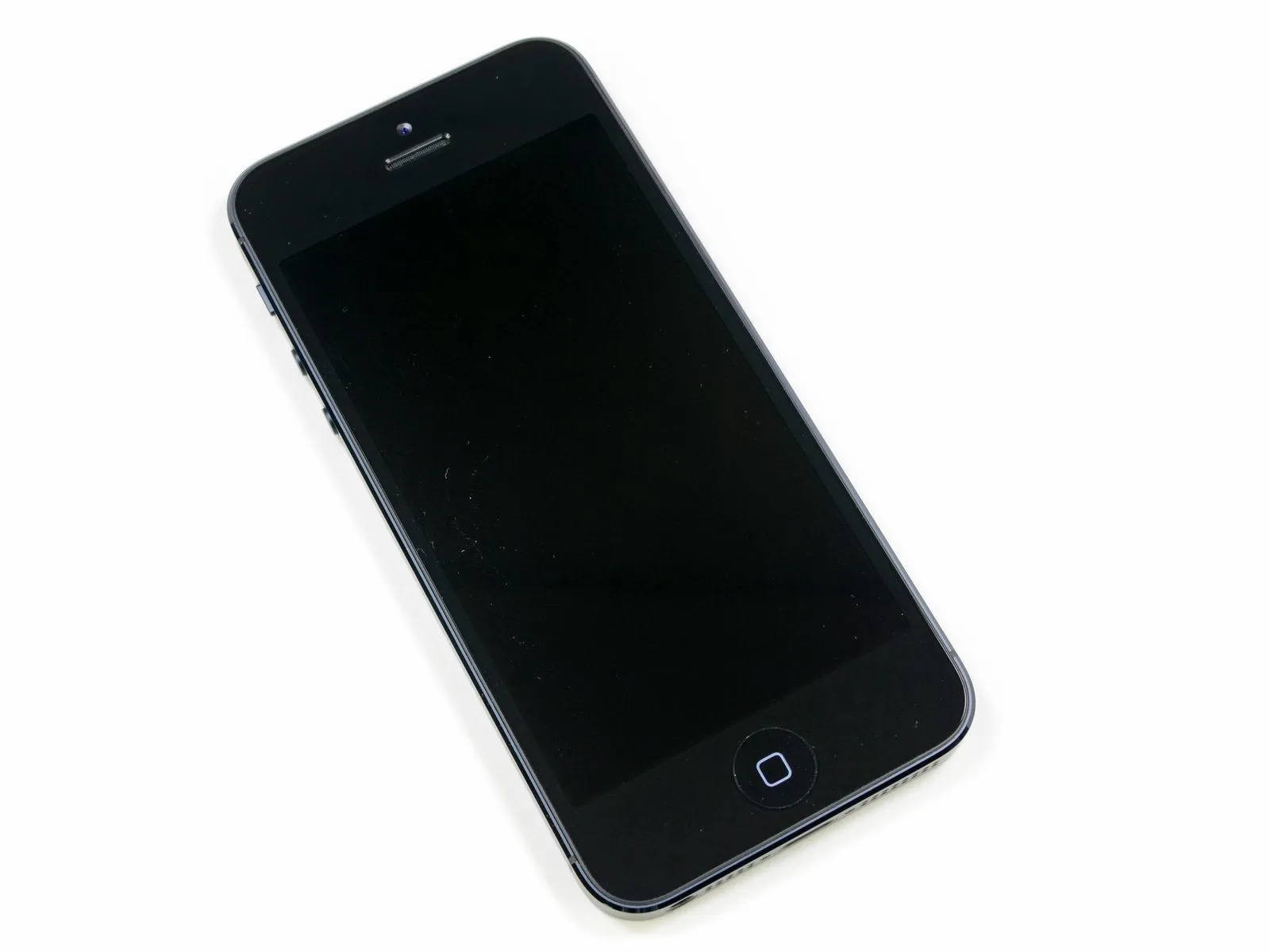
This is the iPhone 5, representing the sixth generation of Apple's iPhone line.
Begin the iPhone 5 disassembly process; this procedure represents a significant advancement in device teardown techniques.
- Stay updated on our disassembly projects and related news by subscribing to our Twitter feed.
- Follow iFixit updates by visiting their page on the Facebook platform.
Step 1 | iPhone 5 Teardown


We appreciate MacFixit Australia’s assistance, as they generously provided their Melbourne location for this disassembly. Their store offers Mac and iPhone upgrades, accessories, and iFixit toolkits for purchase.
Step 2
The screen measures 4 inches diagonally and has a resolution of 1136 by 640 pixels, resulting in a pixel density of 326 pixels per inch.
The device incorporates an Apple A6 system on a chip (SoC).
An 8-megapixel iSight camera.
An 8-pin electrical connector is used for the Lightning interface.
Ensure the device can communicate wirelessly using the 4G LTE cellular network.
The operating system version is iOS 6.
Step 3
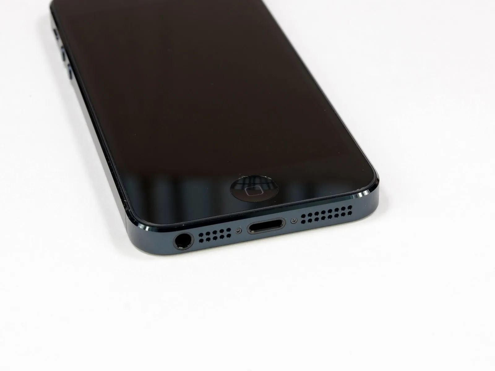
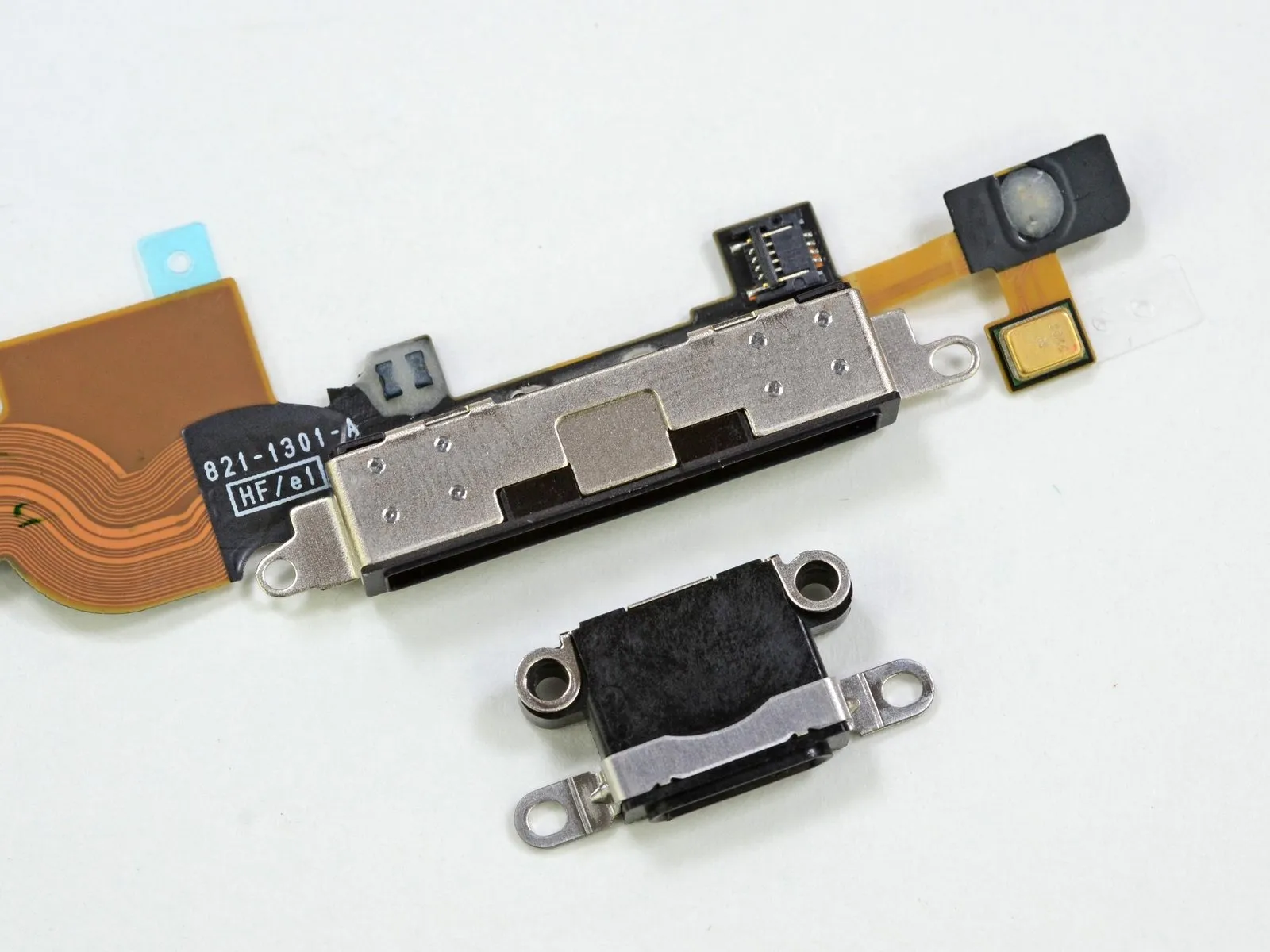
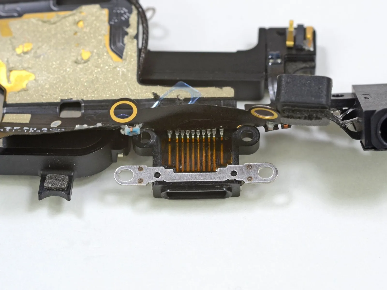
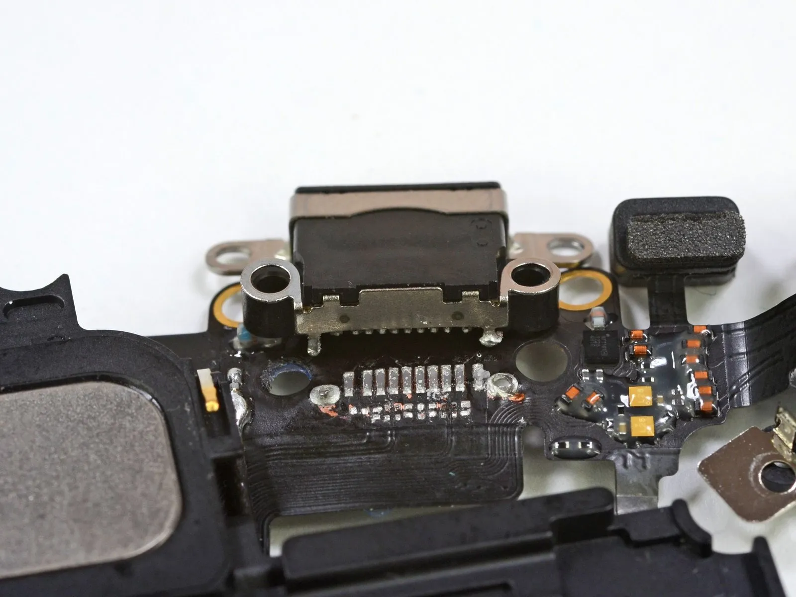
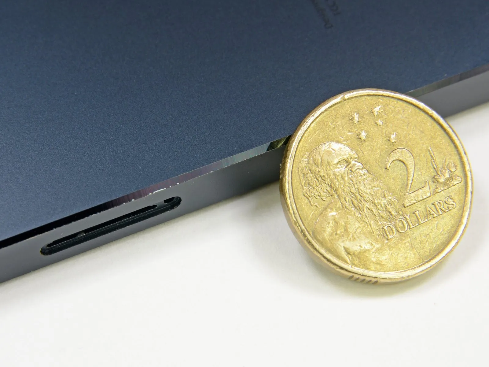
The bottom of the device now features a replacement of the original, sizable 30-pin dock connector with a smaller Lightning connector.
Located on the iPhone's lower edge, adjacent to the redesigned speaker microphone grille, which features a pattern of individual apertures instead of a mesh covering, you'll find the headphone jack.
The bezel is constructed from slate material, a departure from the 4S model's stainless steel design, and the transition between the bezel and the front and rear case housings exhibits a beveled edge.
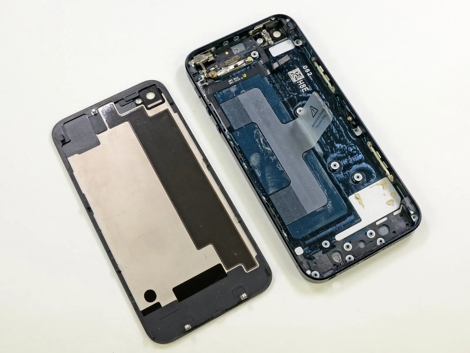
Step 4
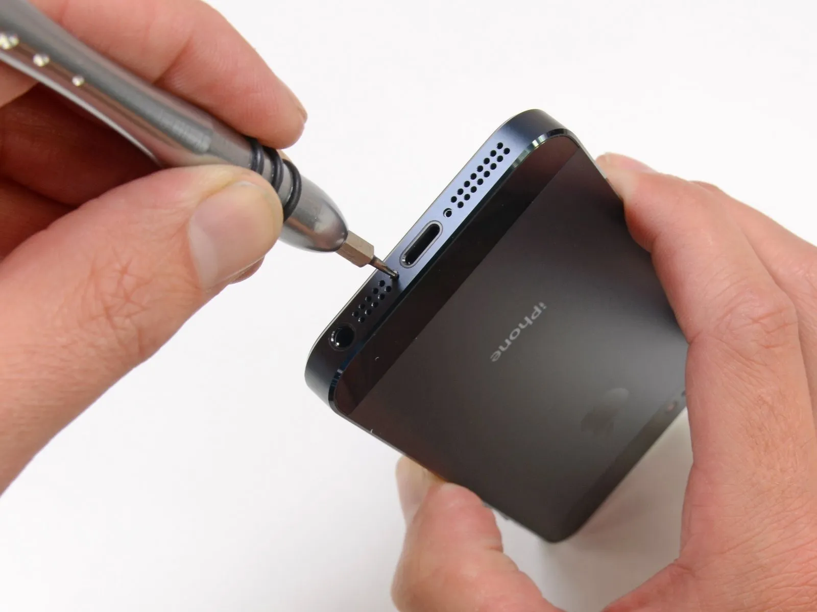
Because Apple consistently utilizes the same pentalobe screwhead design across iPhone 4 and 4S models, a unique iPhone 5 Liberation Kit was developed to accommodate subtle variations in screw shaft dimensions compared to the existing iPhone 4/4S Liberation Kit.
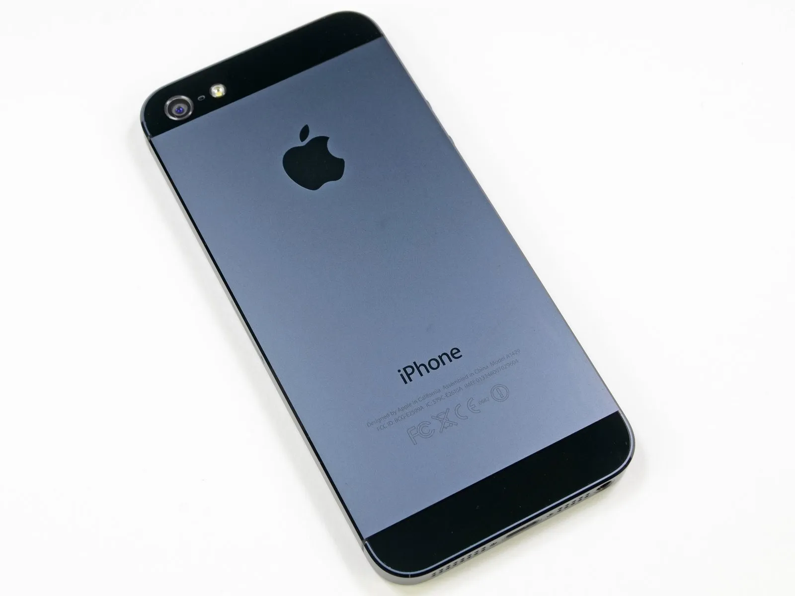
The device's rear enclosure design echoes the iPhone 3GS aesthetic, but incorporates the iPhone 4’s squared-off form factor, modified with a beveled edge.
Step 5
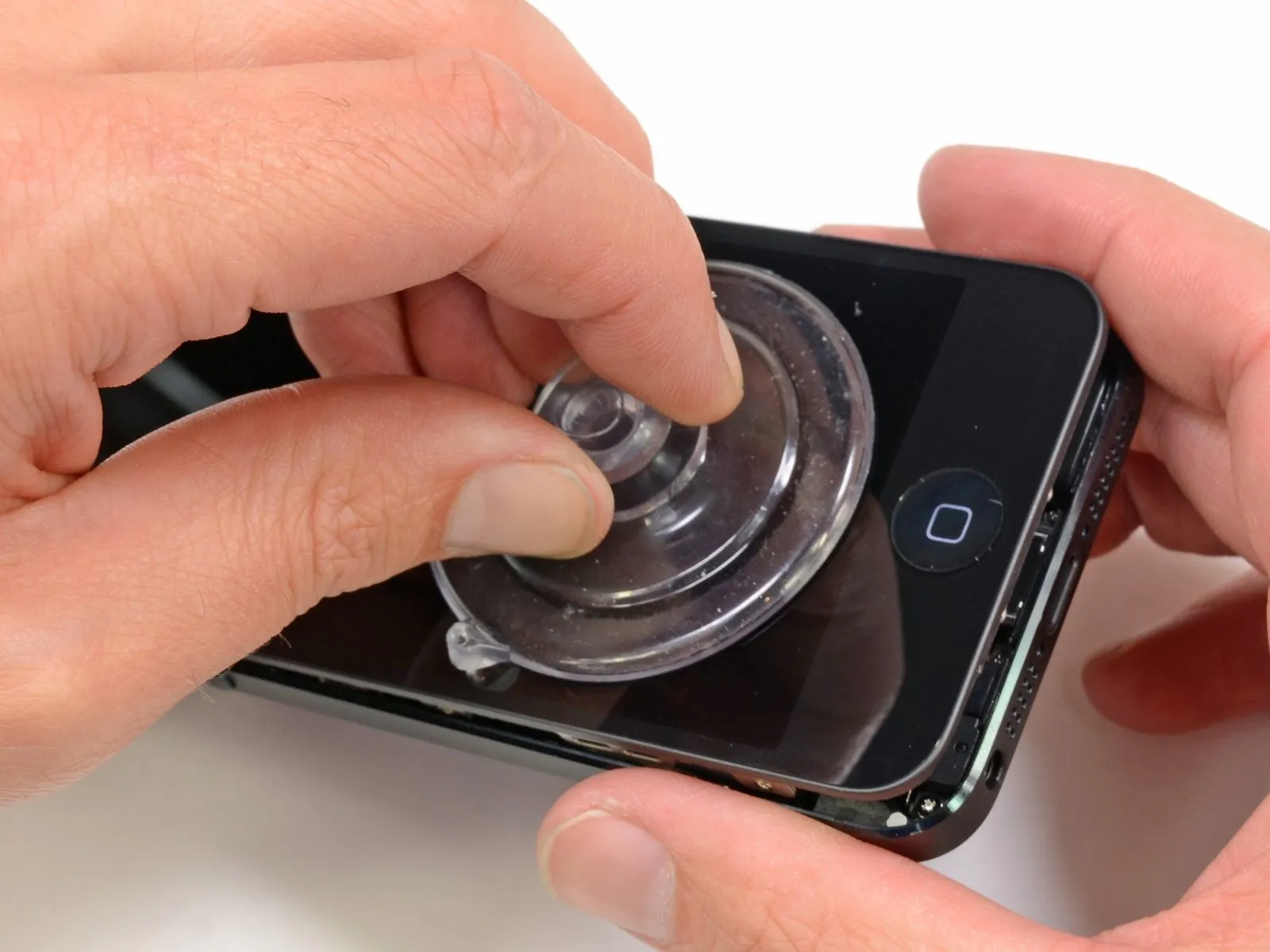
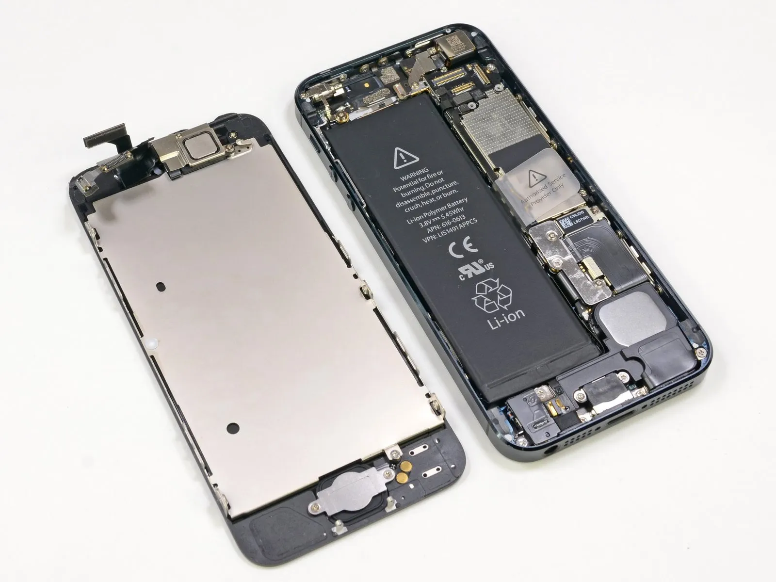
The design of the iPhone 5, which allows for front-to-back access, simplifies the process of replacing a damaged display.
The display isolation process for this iPhone requires 38 steps, a complexity level similar to that of an iPhone 4S repair, suggesting it represents a significant improvement in repair accessibility among iPhones.
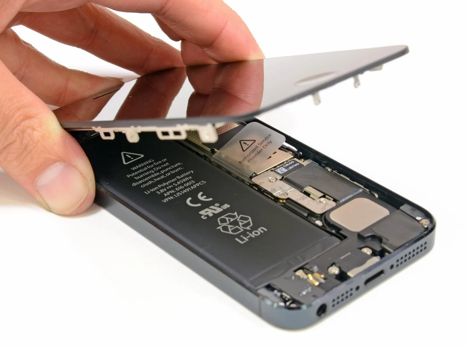
Step 6
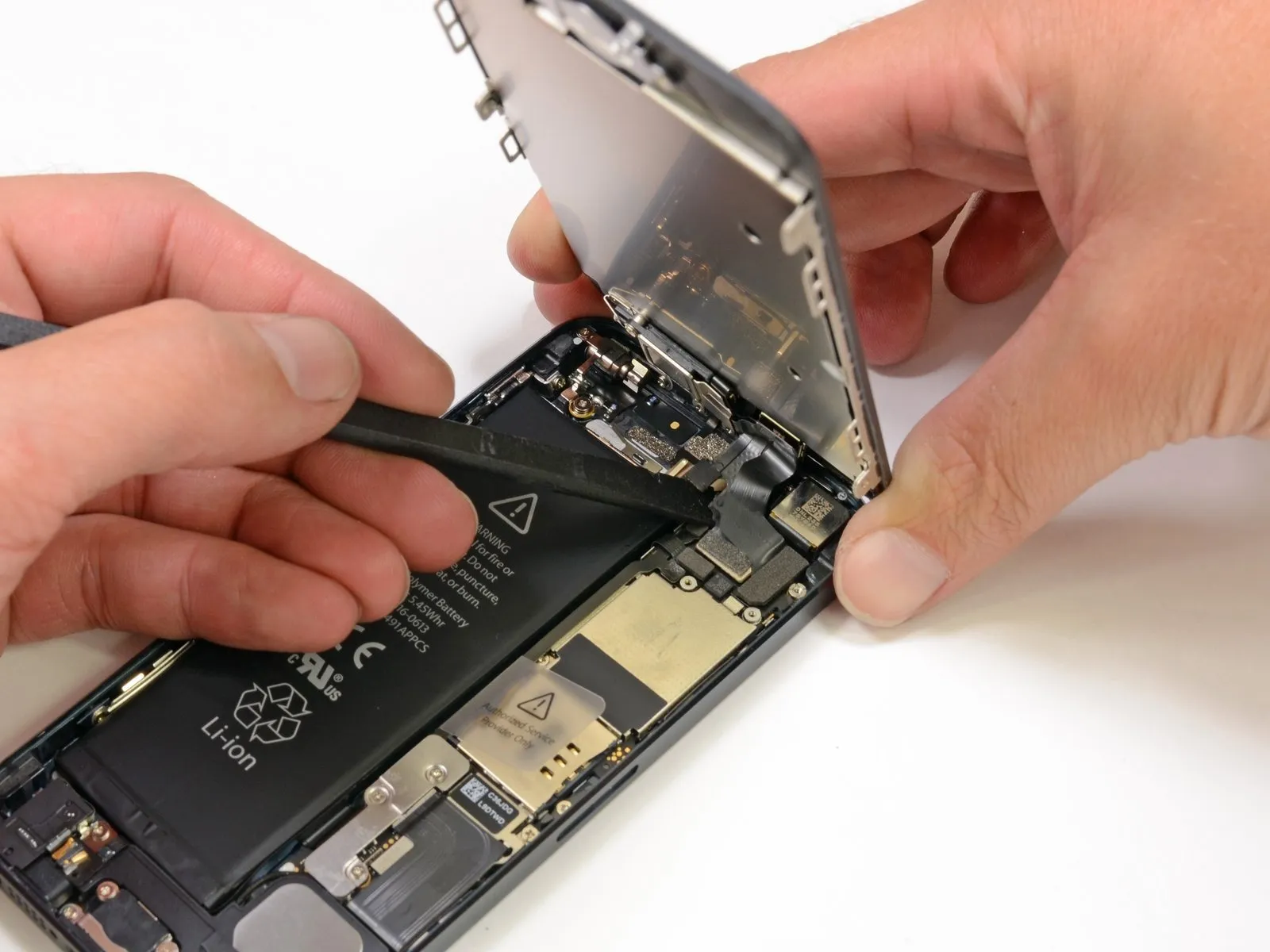
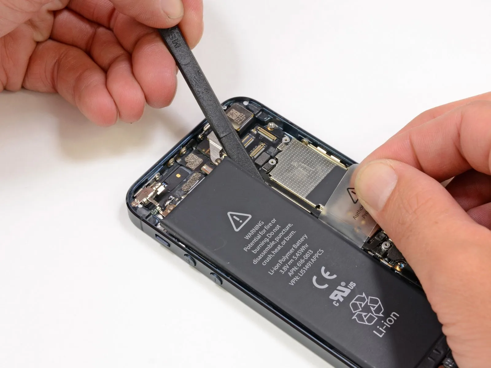
Using the provided spudger, carefully leverage the display connector to release the display assembly.
The screen module is remarkably simple to detach, reminiscent of the iPhone 3GS design.
Individuals specializing in screen repair, including those who address cracks and implement fixes, will find this guide beneficial.
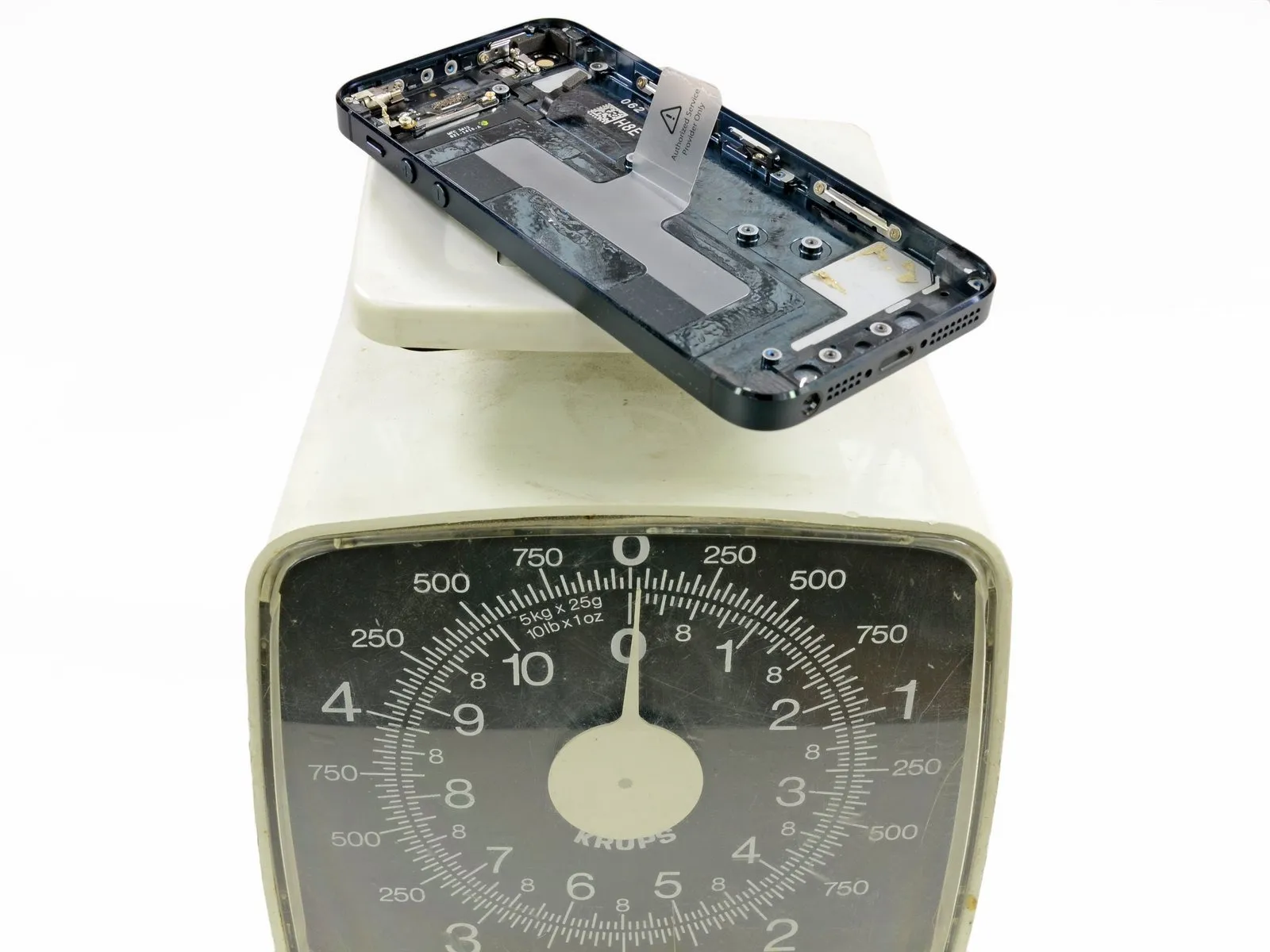
Step 7
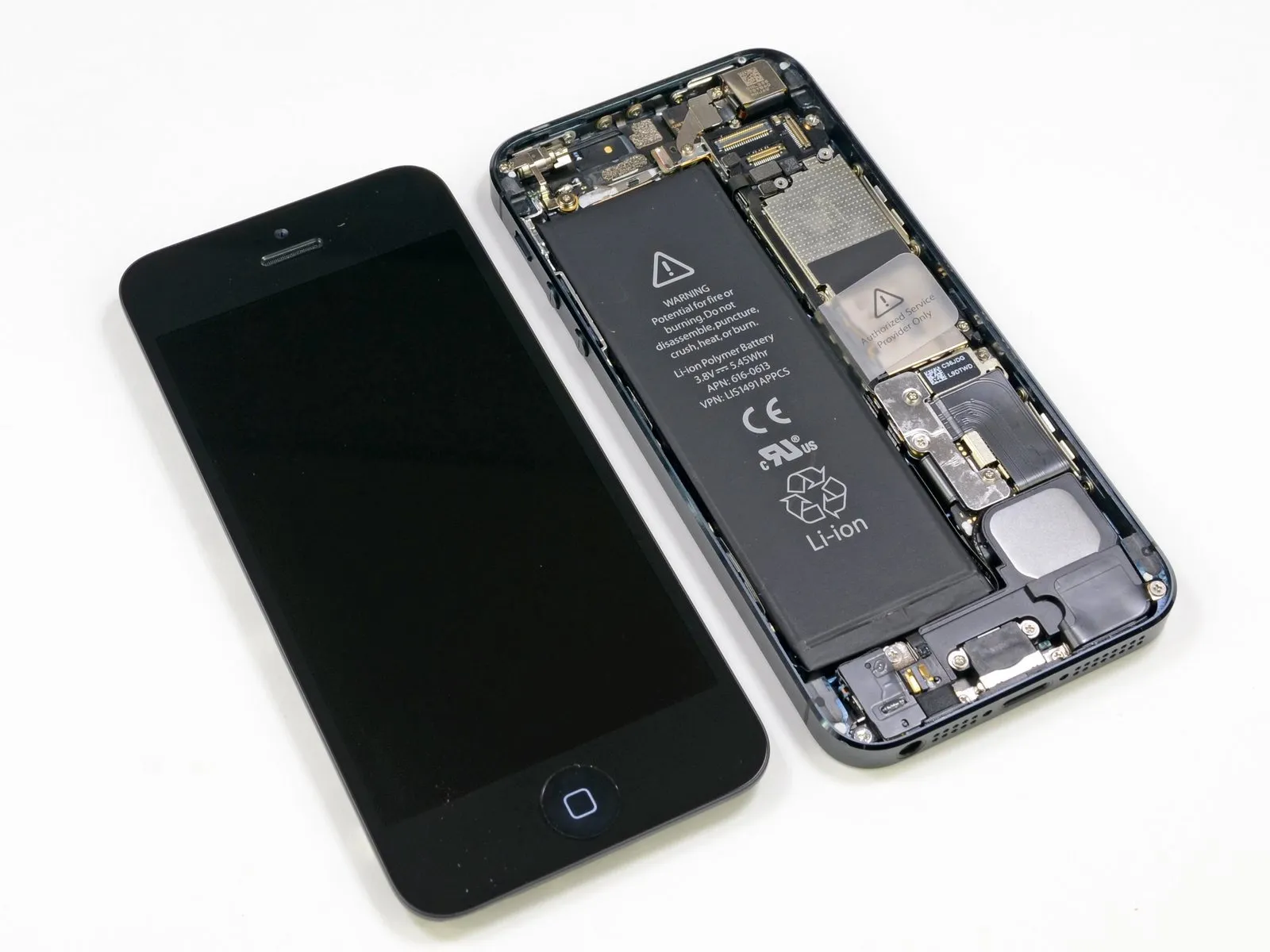
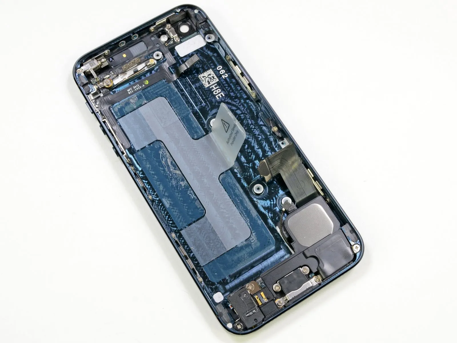
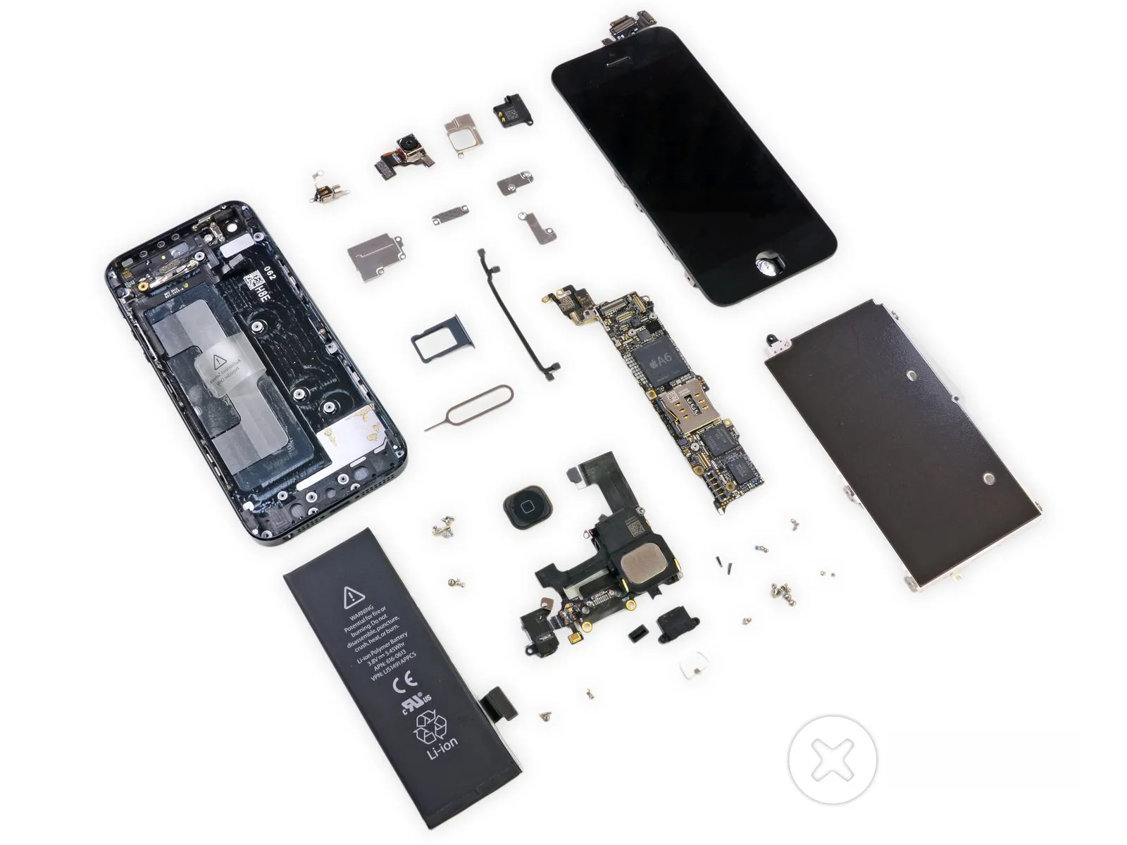
Observe the component; note the increased capacity of the battery.
Ensure proper antenna attachment, verifying all connectors are securely fastened.
Confirm the presence of one speaker.
Inspect the camera assembly for damage and ensure all lenses are securely mounted, referencing the service manual for specific torque specifications (typically 0.8 Nm) when re-installing.
Ensure the device is a vibrator.
Inspect the home button assembly for damage or malfunction.
Throughout this process, carefully observe and document the location and condition of all parts as they are detached.
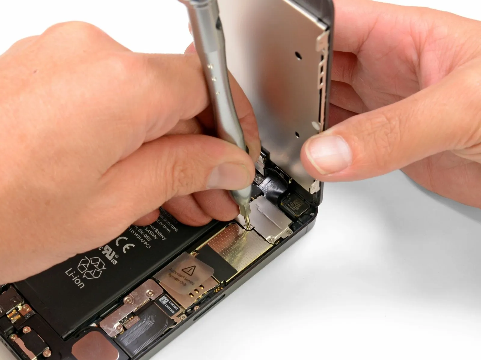
Step 8
The battery connector is secured to the logic board by a metal bracket, which is fastened with three screws requiring a Phillips #000 screwdriver.
The process is likely repeating a previously encountered step.
Removing the display assembly from a 3GS proved straightforward, whereas battery replacement presented a greater challenge; conversely, the 4 and 4S models required 38 distinct steps for display removal, but battery access was simple. Apple’s design appears to have evolved toward easier disassembly, now permitting both the display assembly and battery to be detached with minimal steps.
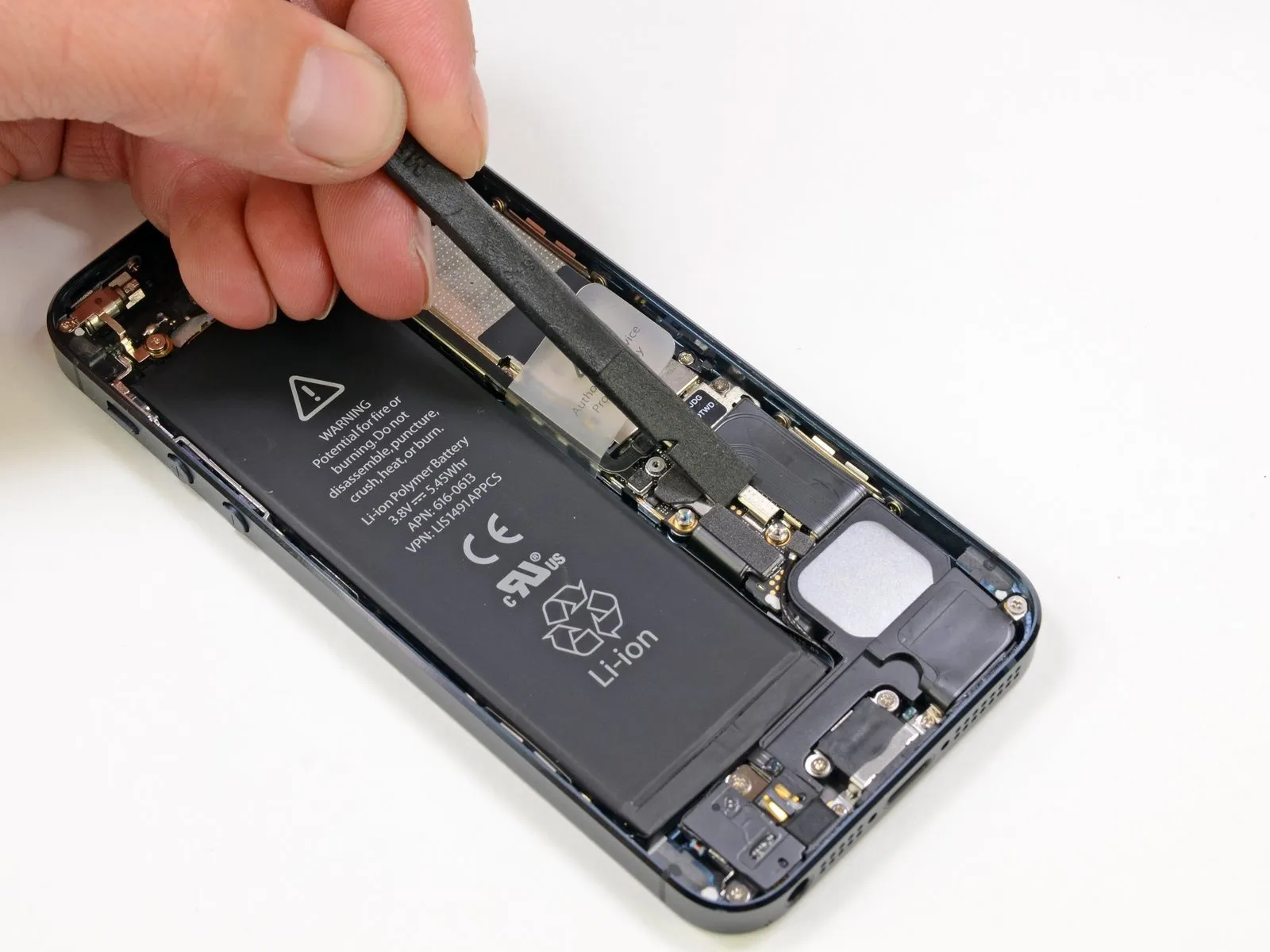
Step 9
Attempting to separate the battery cells in soft packs risks causing a dangerous overheating situation.
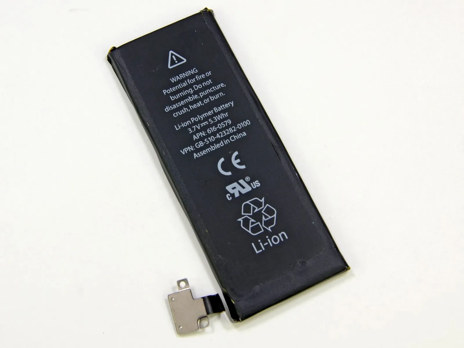
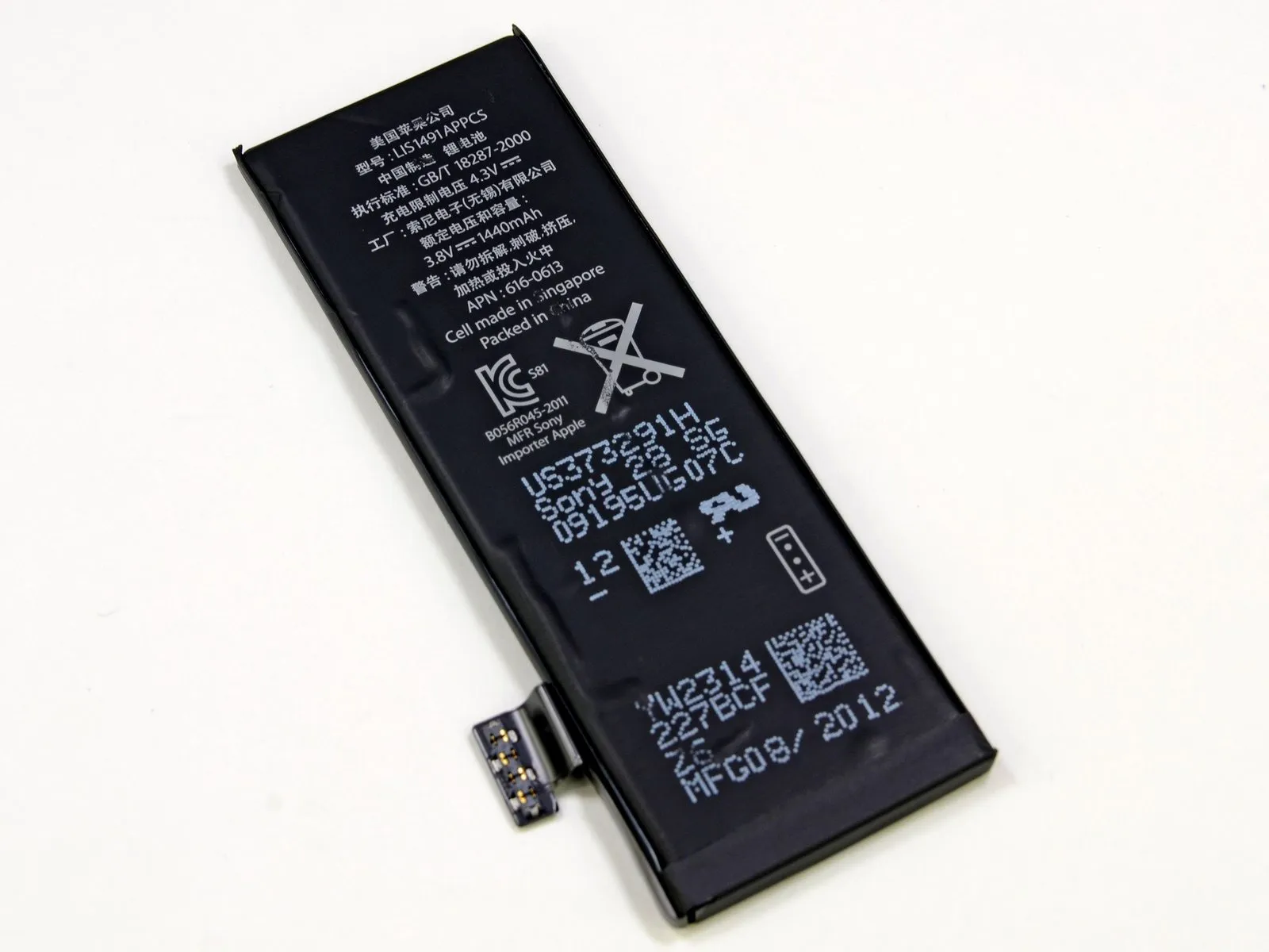
The iPhone 5 utilizes a battery employing a distinct chemical composition from the iPhone 4S, exhibiting a voltage increase and a modest rise in capacity. A comparison of the specifications follows.
- The iPhone 5 battery delivers a capacity of 1440 milliampere-hours and a power output ranging from 3.8 to 5.45 watts, providing up to 8 hours of talk time when using a 3G network.
- The device can remain in standby mode for as long as 225 hours.
- The iPhone 4S battery delivers a capacity of 1432mAh, a power output of 5.3Wh at 3.7V, and supports up to 8 hours of talk time when connected to a 3G network.
- The device can remain in a low-power state for as long as 200 hours before needing to be recharged.
- The Samsung Galaxy S III battery delivers a capacity of 2100 milliampere-hours, a power output of 7.98 watt-hours, and an operating voltage of 3.8 volts. Utilizing a 3G network, it provides up to 11 hours and 40 minutes of continuous talk time.
- The device can remain in standby mode for a maximum duration of 790 hours.
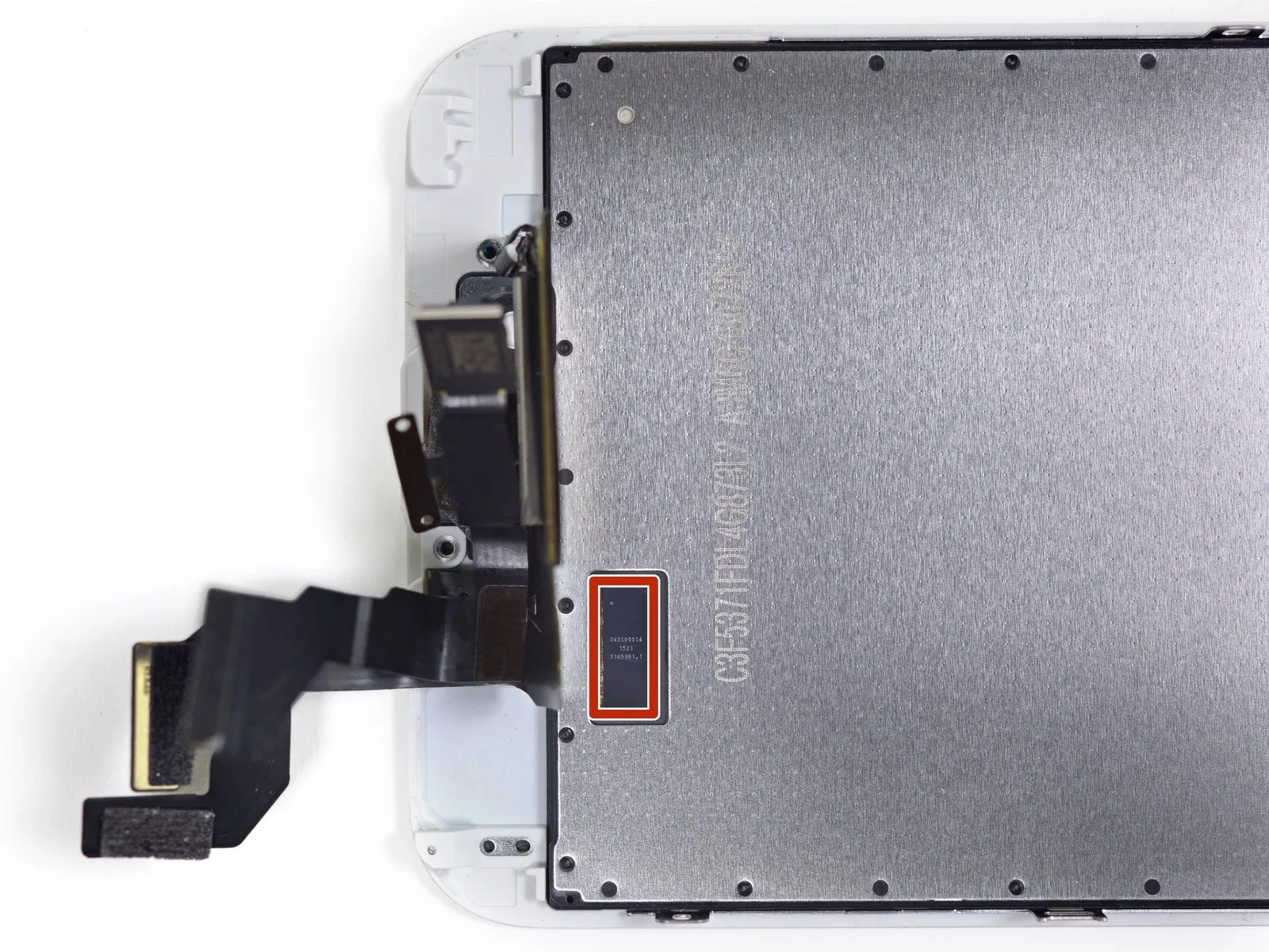
Examination of the battery's rear reveals markings indicating its manufacturer is Sony, and the cells were produced in Singapore. Online research supports this identification, suggesting Sony's involvement in the battery's production.
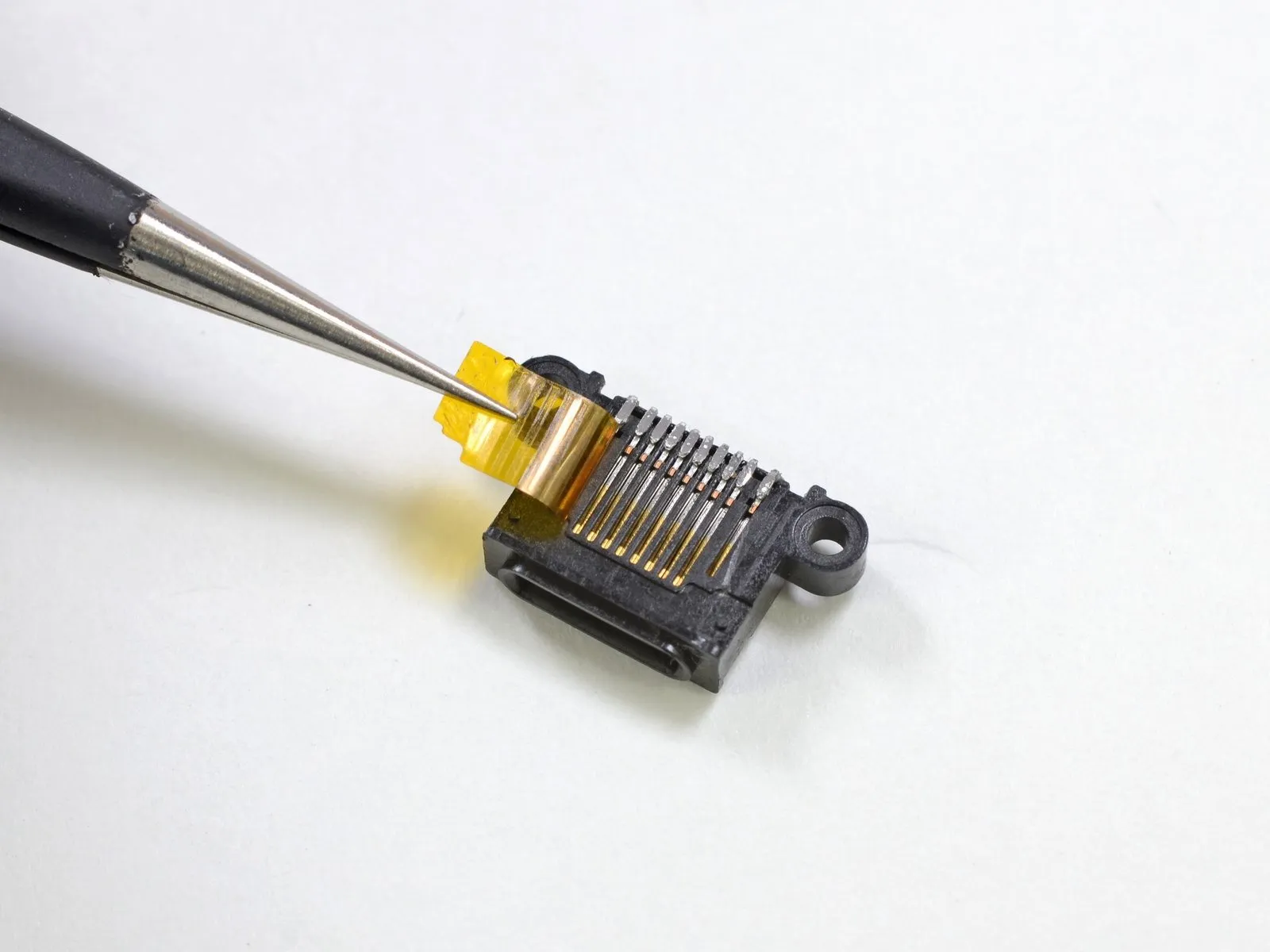
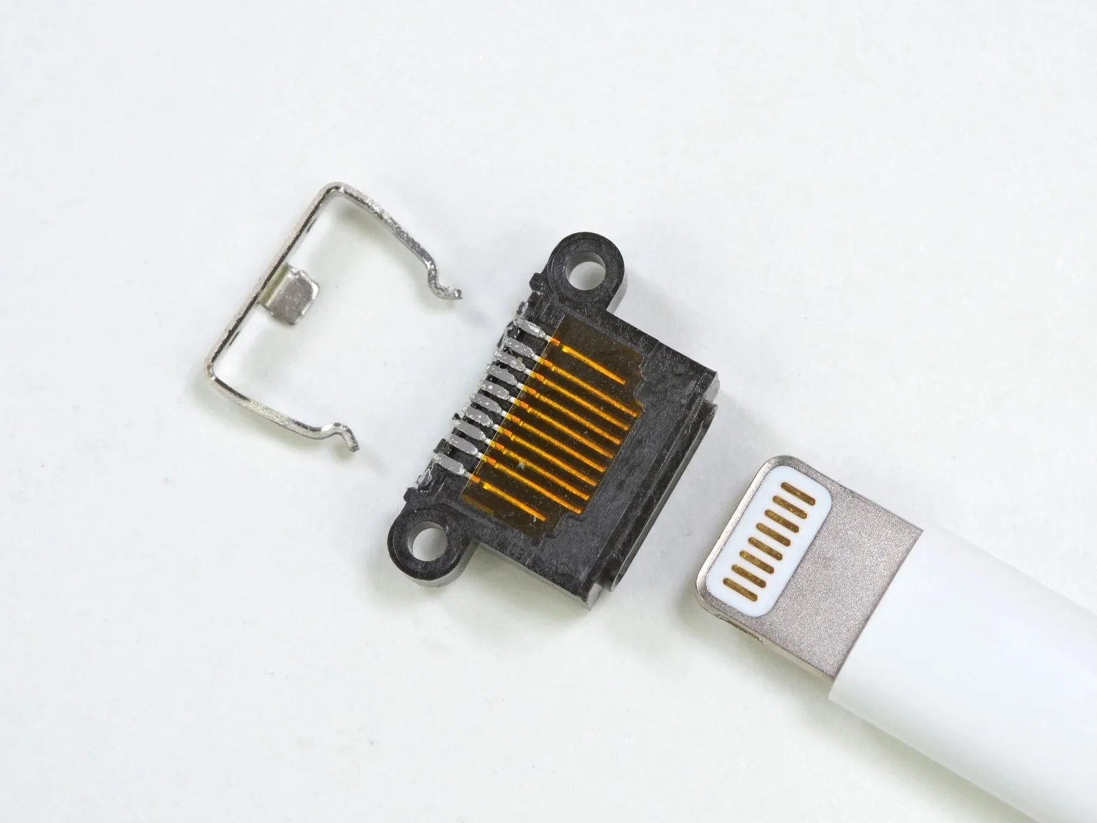
Step 10
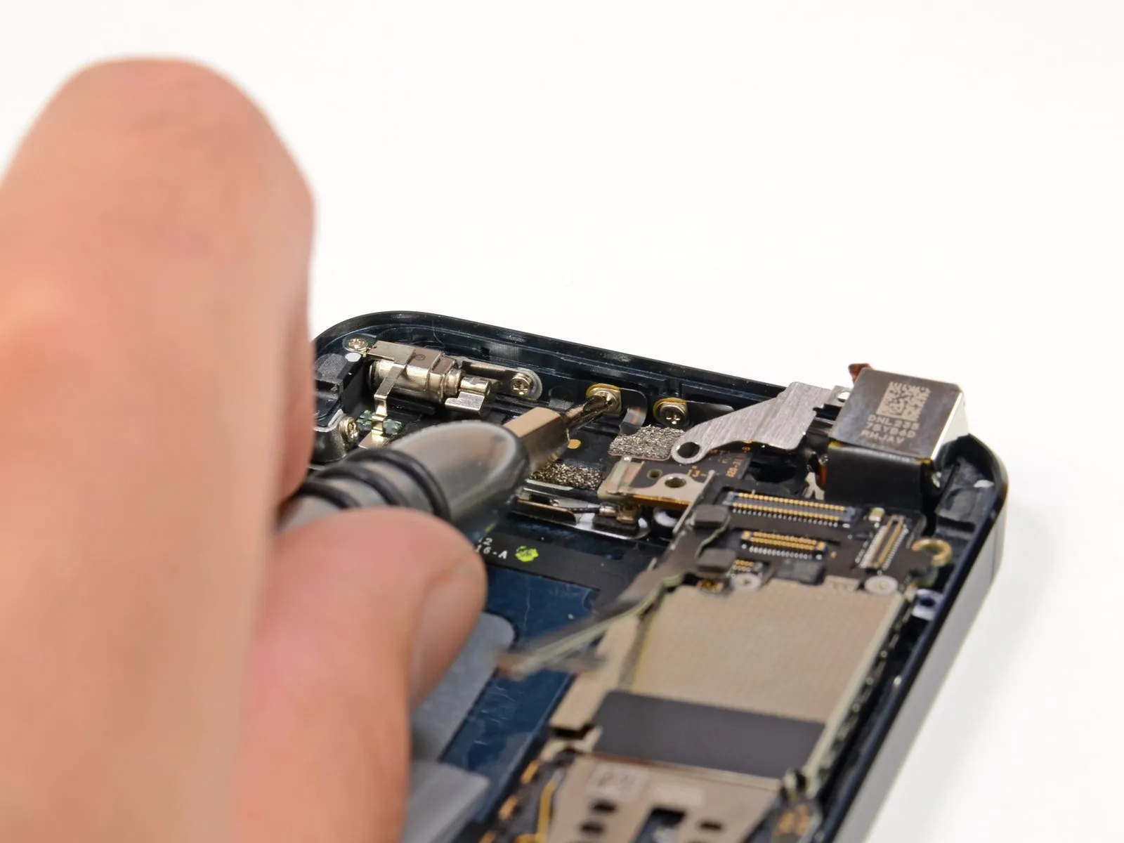
Because the spring contacts simplify repairs, thoroughly cleaning all components is essential prior to reassembly; contamination from fingerprints can interfere with the metal contacts' function and lead to component malfunctions.
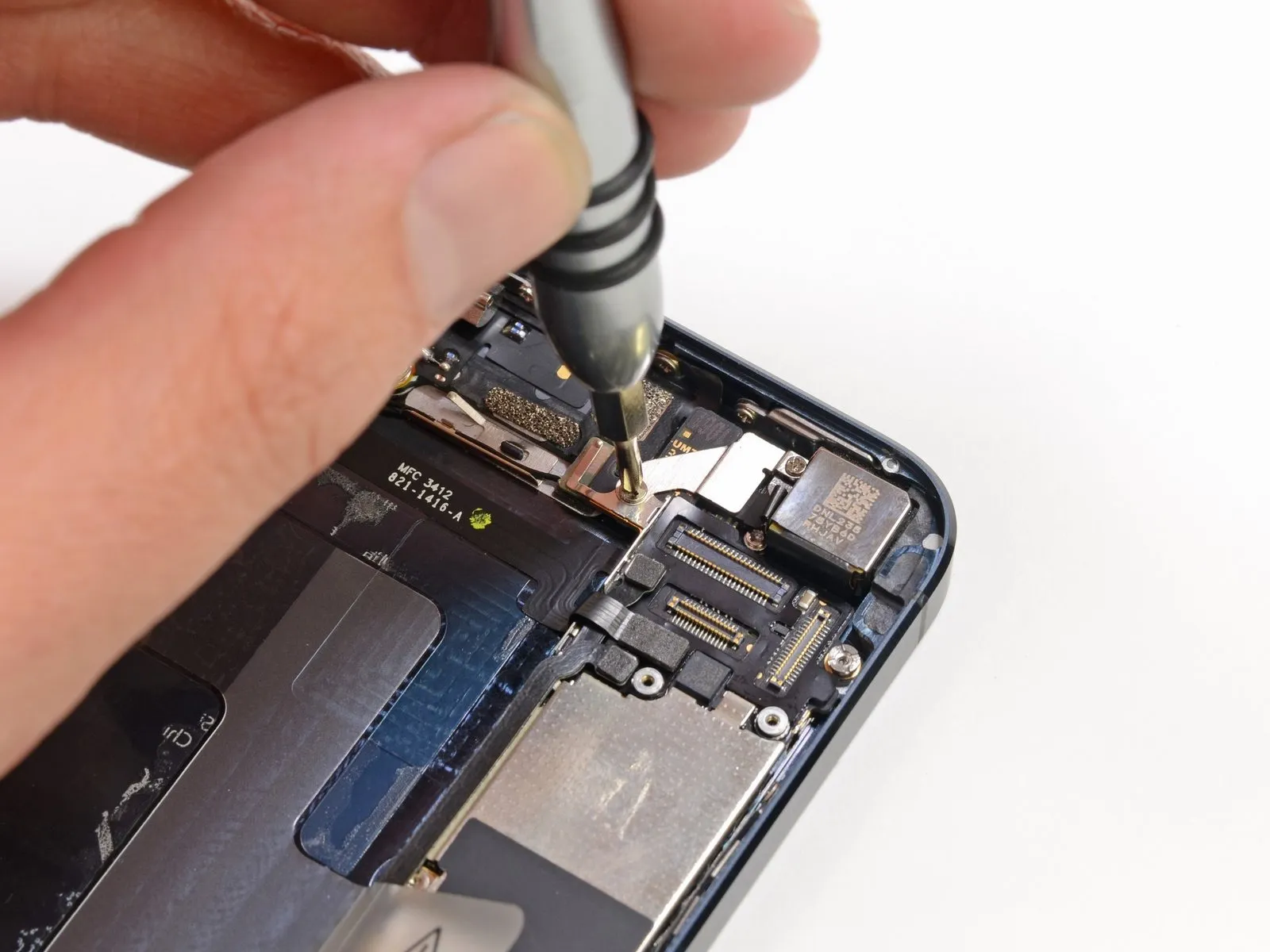
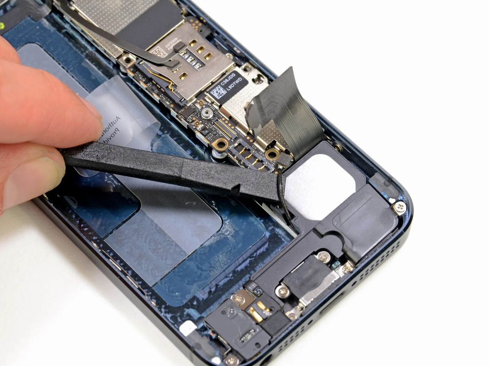
The metal component linking the front camera assembly to the rear camera assembly may function as an antenna; its purpose remains undetermined.
Using a spudger, carefully detach one antenna connector from the logic board, located close to the battery.
The iPhone 4S design allocated this specific area to house the cellular antenna, and its definitive function remains undetermined pending further investigation.
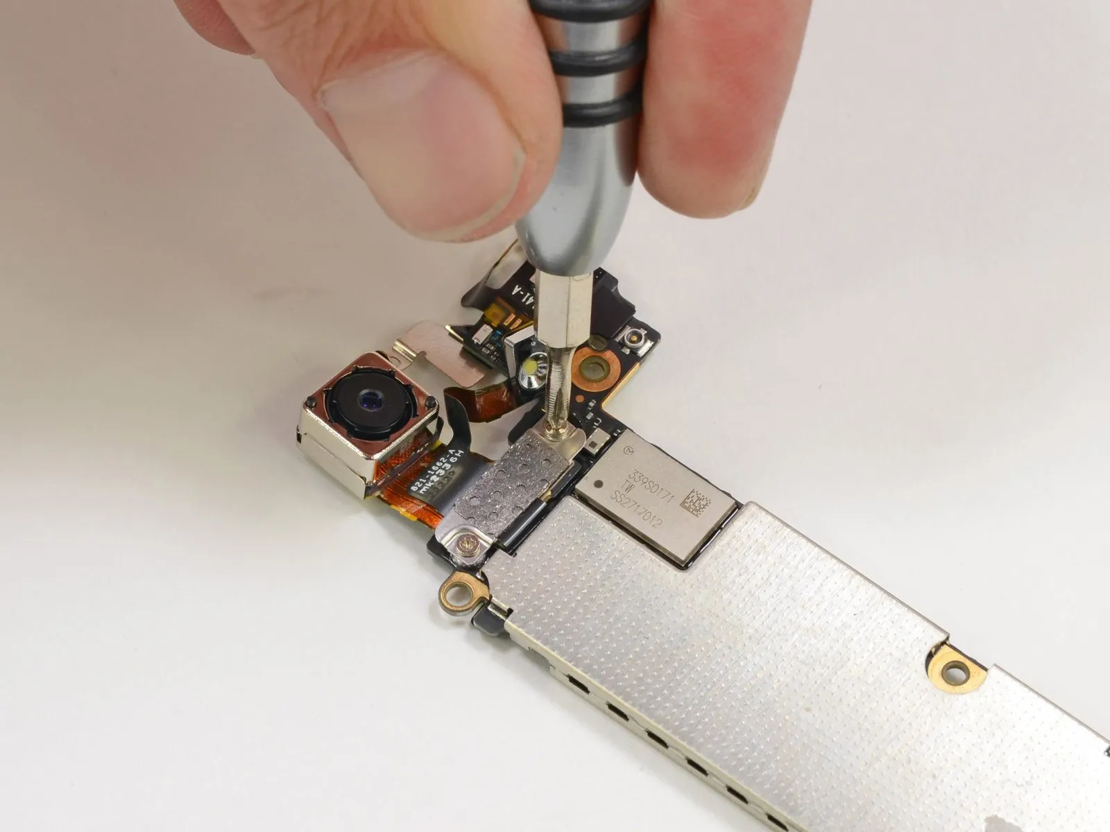
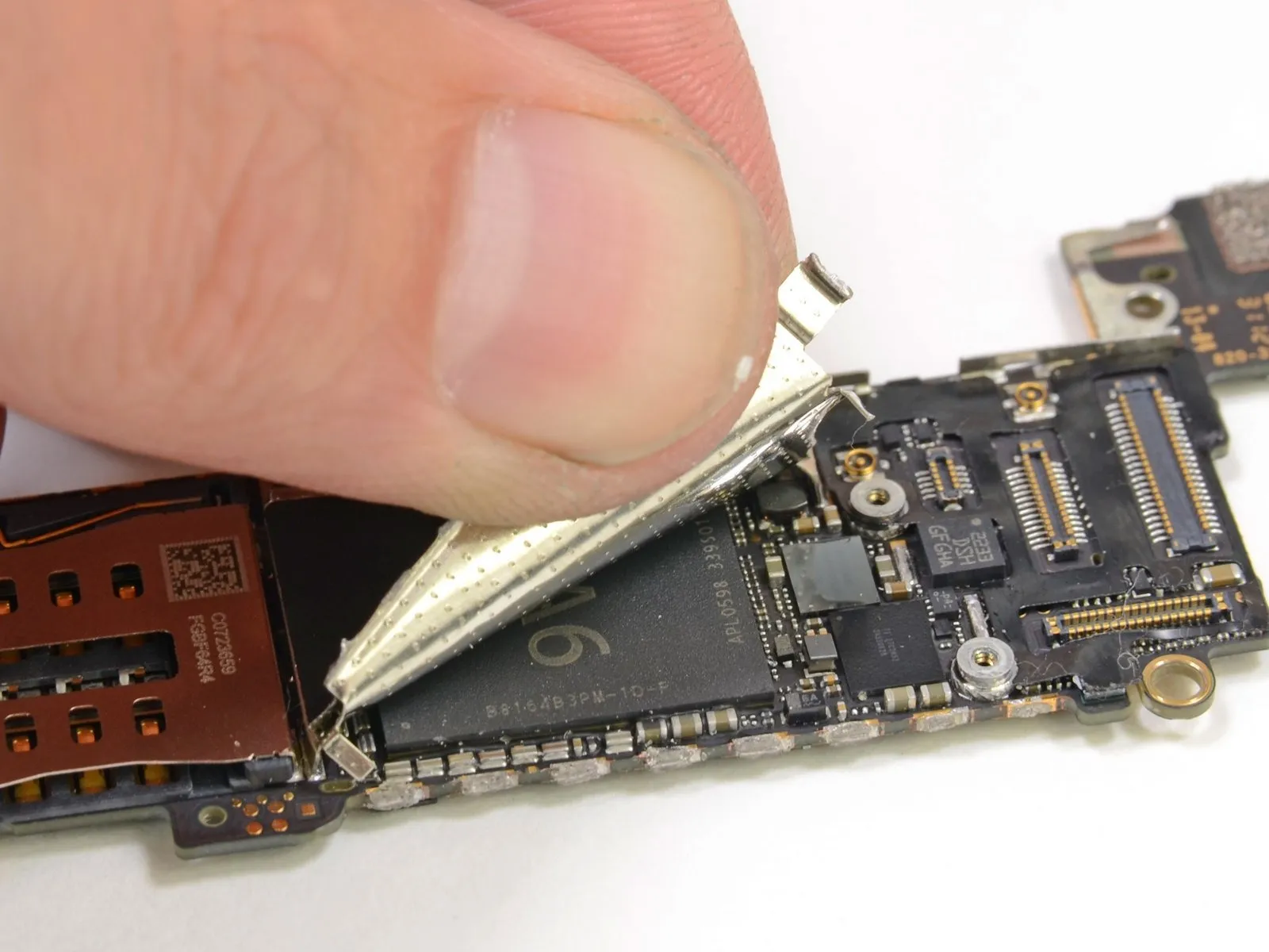
Step 11
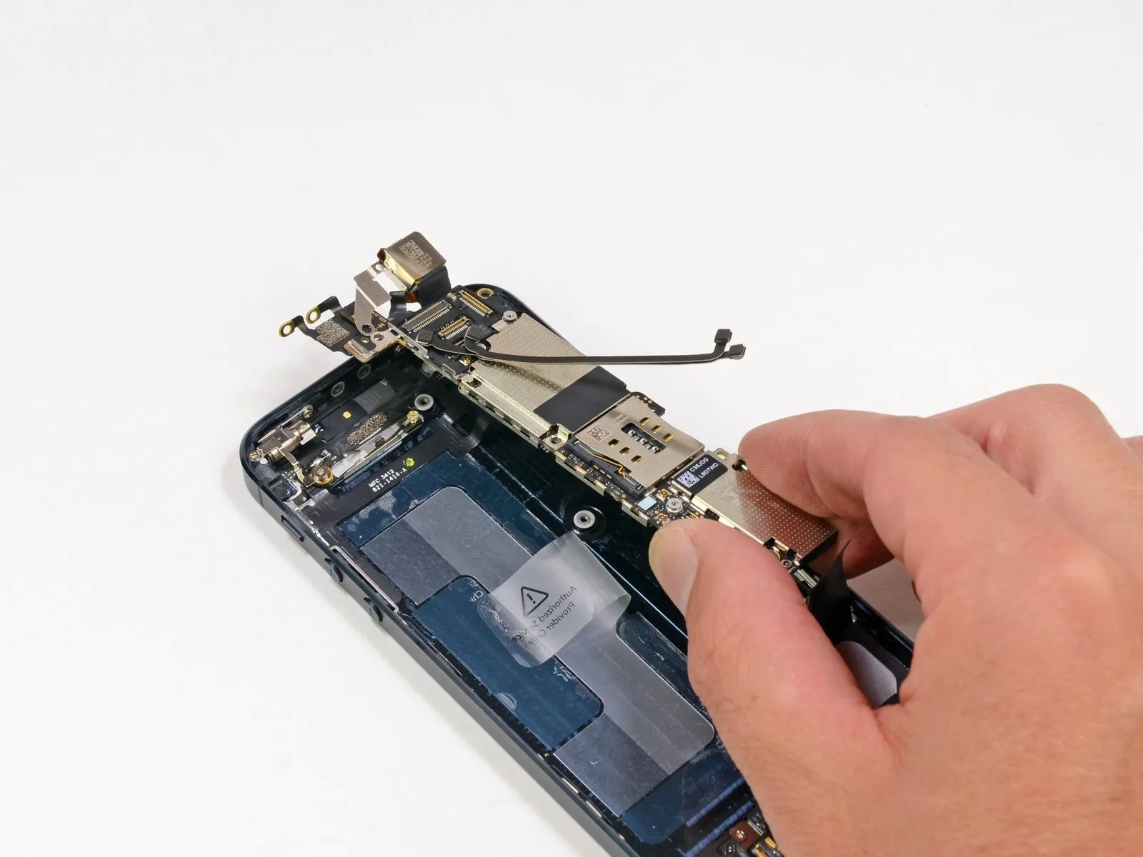
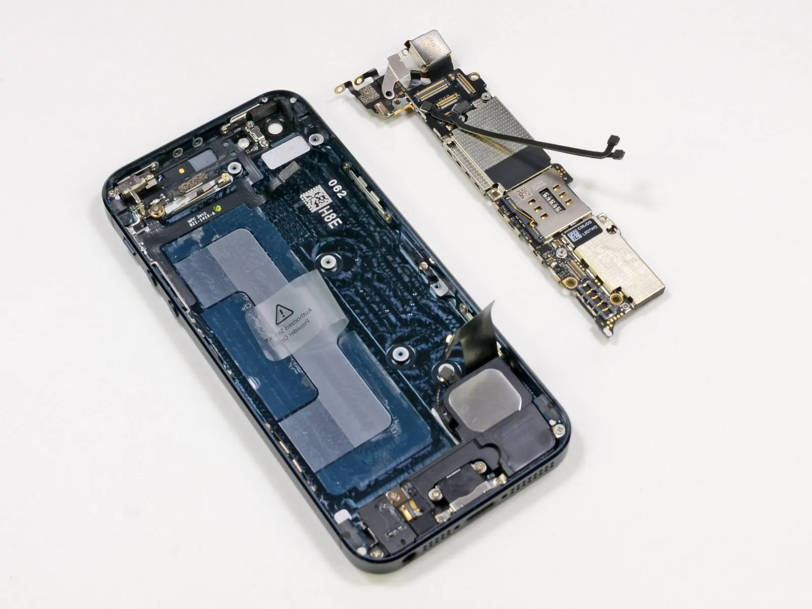
Carefully raise the logic board vertically, disengaging it from the rear case.
Removing the logic board simultaneously releases the attached 8-megapixel iSight camera, as these parts are integrated; several other components remain secured within the rear case, demonstrating the device's modular design.
This device earns a repairability score of one point.
Step 12

Immediately remove the drinks.
Place the components in a refrigerator to maintain a cool environment.
The provided text is nonsensical and does not contain a repair instruction. Therefore, it cannot be rewritten to preserve technical meaning.
Step 13

To ensure long-term stability and prevent connector loosening, Apple emphasizes the importance of secure seating for all connections.
We extend our sincere gratitude to Chipworks for their invaluable assistance in identifying the integrated circuit packages on the logic board, a process that extended late into the night. Their expertise, combined with our own efforts, is illustrated in the images that follow.
Step 14
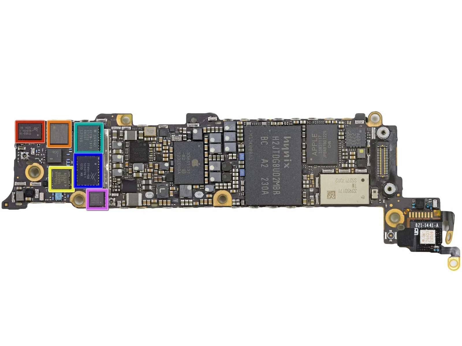
Skyworks produces the 77352-15, a module that amplifies signals for GSM, GPRS, and EDGE cellular networks.
The RF antenna switch module is designated SWUA 147 228.
The UMTS band utilizes a TriQuint 666083-1229 module, incorporating a WCDMA/HSUPA power amplifier and a duplexer.
The Avago AFEM-7813 is a module that combines a power amplifier and FBAR filter, designed for use in dual-band LTE networks operating on bands 1 and 3.
Skyworks manufactures the 77491-158, a CDMA power amplifier module.
LTE band 13 power amplifier, model A5613, manufactured by Avago.
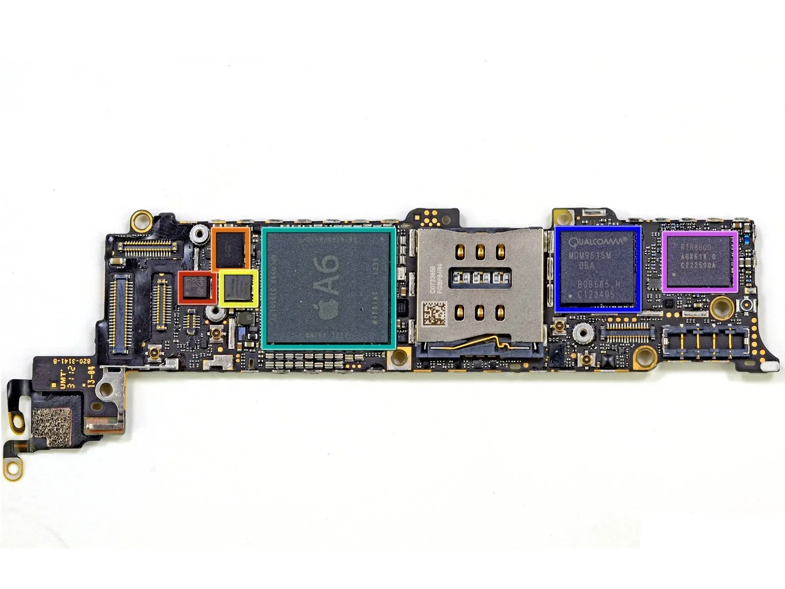
Step 15

The RF power management integrated circuit is a Qualcomm PM8018.
The NAND flash memory module is a Hynix H2JTDG2MBR component, featuring a capacity of 128 Gigabits, equivalent to 16 Gigabytes.
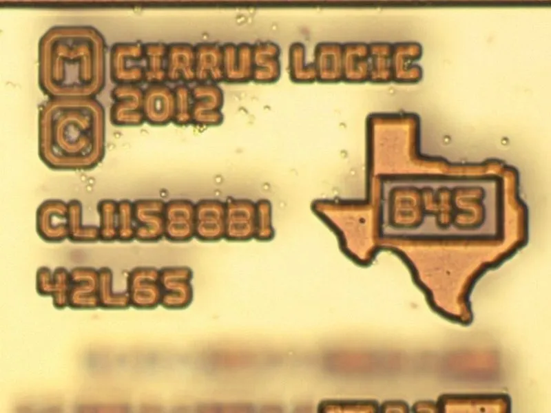
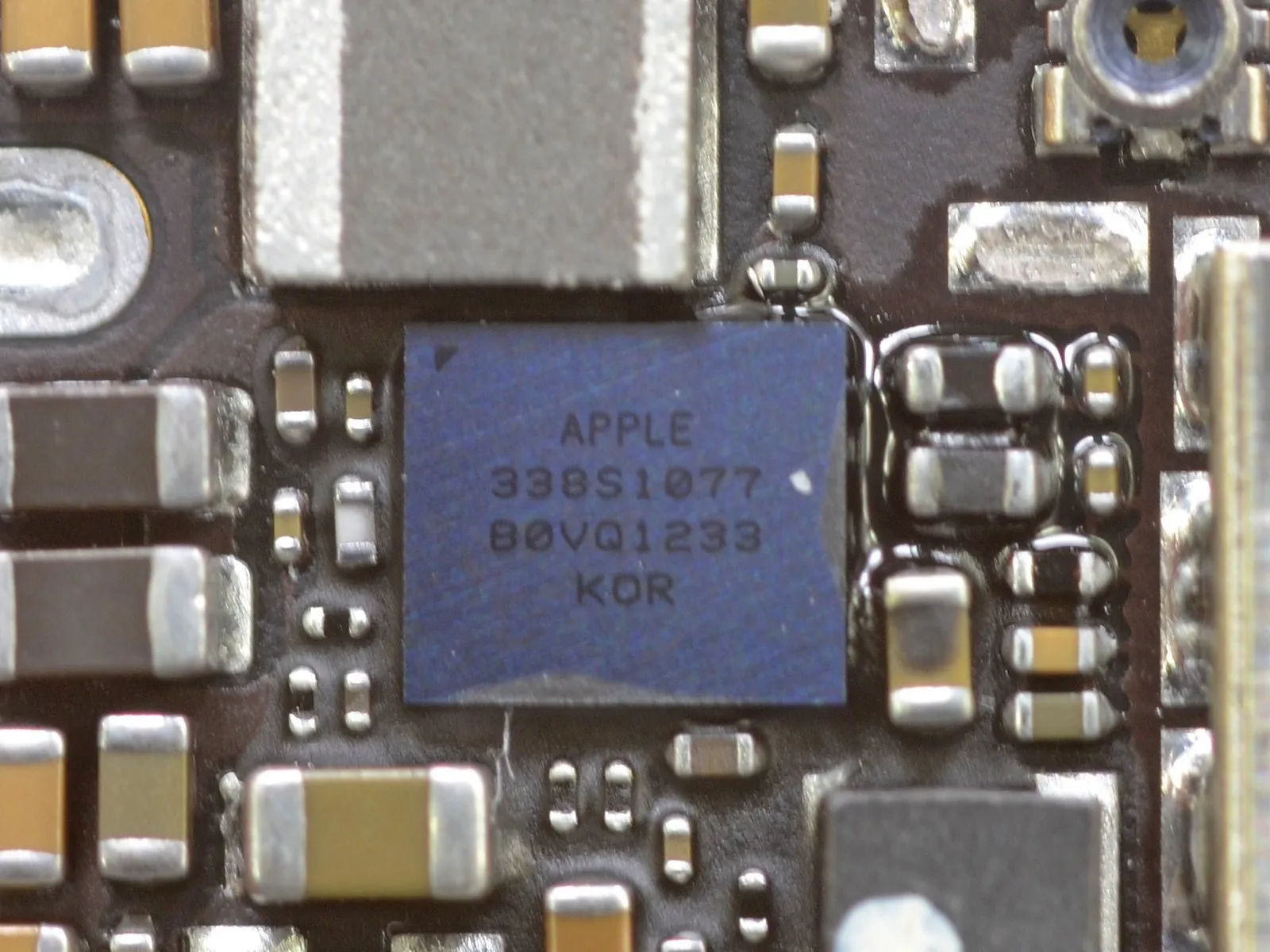
The device labeled Apple 338S1131 contains a power management integrated circuit, alongside Apple 338S1117 Cirrus Logic Class D amplifiers; the integrated circuit's internal die, visible in the second image, is manufactured by Cirrus Logic but is not an audio codec.
This three-axis gyroscope, the STMicroelectronics L3G4200D (identified by part numbers AGD5/2235/G8SBI), delivers low power consumption and is the same model utilized in devices like the iPhone 4S and iPad 2, as well as numerous other high-end smartphones.
The Wi-Fi module utilizes a Broadcom BCM4334 chip and is manufactured by Murata, identified as part number 339S0171.
Step 16
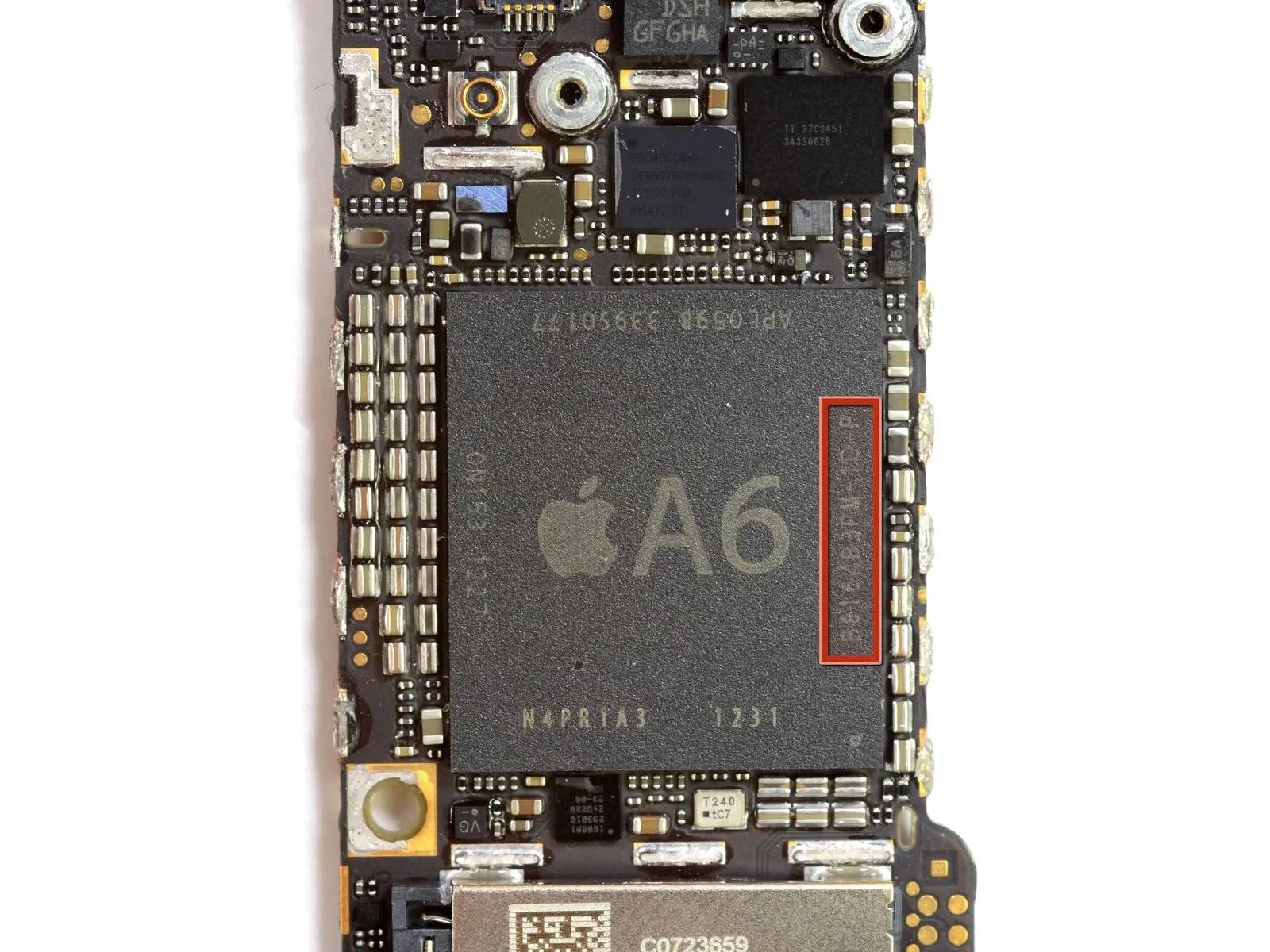
Apple’s A6 processor, a System-on-Chip (SoC), marked a departure for the company with its unique architecture built upon the ARMv7 instruction set.
Apple can customize the A6 processor's functionality to meet their specific requirements due to its non-ARM architecture.
Chipworks analysis indicates that the silkscreen marking "B8164B3PM" identifies a 1GB Elpida LP DDR2 SDRAM module.
Evidence from Apple's Keynote presentation definitively identified Samsung RAM, specifically the K3PE7E700F model, as being used within the A6.
Recent shifts in Apple's procurement strategy have involved decreasing their RAM chip orders from Samsung, prompting speculation regarding potential opportunities with Elpida and the possibility of Samsung components reappearing in future Apple devices.
Step 17
An audio codec functions as a combined digital-to-analog and analog-to-digital converter, enabling the encoding and decoding of audio input and output signals within a single component.
Step 18
This is a three-axis linear accelerometer from STMicroelectronics, model number 2233/DSH/GFGHA, designed for ultra-low power consumption and high performance.
The device incorporates a Texas Instruments 343S0628 system-on-chip, specifically designed for touch screen functionality.
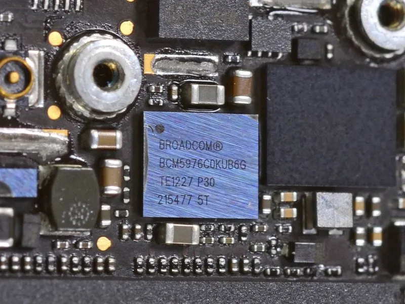
The device incorporates a Broadcom BCM5976 touchscreen controller.
To accommodate the increased display dimensions, Apple opted for a system utilizing multiple controller chips, mirroring the design approach previously implemented in iPad models.
The device utilizes an Apple A6 application processor.
LTE modem: Qualcomm MDM9615M
The Samsung Galaxy S III utilizes a Qualcomm RTR8600 transceiver, a multi-band/mode RF component.
Step 19
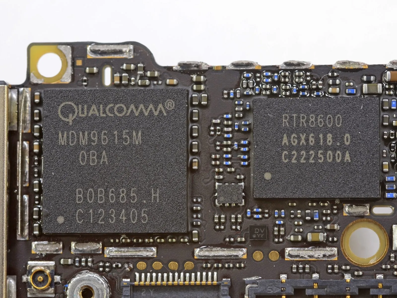
The device utilizes a Qualcomm MDM9615M modem to provide 4G LTE connectivity.
Following a period of anticipation and competitive pressure from Android devices, iPhone users can now experience 4G LTE connectivity. The implications of this enhanced capability remain to be seen.
This modem, the Qualcomm MDM9615M, supports LTE connectivity using both Frequency Division Duplex (FDD) and Time Division Duplex (TDD) methods, alongside HSPA+, EV-DO Rev B, and TD-SCDMA protocols, and is fabricated using a 28 nanometer process.
The MDM9615 chipset enables LTE connectivity with multiple spectrum bands and operating modes, facilitating concurrent voice and data transmission over LTE networks, contingent upon carrier infrastructure support.
The device incorporates a Qualcomm RTR8600 radio transceiver, which works in conjunction with the MDM9615 to enable compatibility with 5 UMTS bands, more than 5 LTE bands, and 4 EDGE bands.
Step 20
The Retina display's touch functionality relies on a collaborative effort, with the Texas Instruments touchscreen controller managing inputs alongside the same chip previously utilized by Apple in the MacBook Air trackpad.
Step 21
Step 22
Step 23
Step 24
Step 25
Step 26
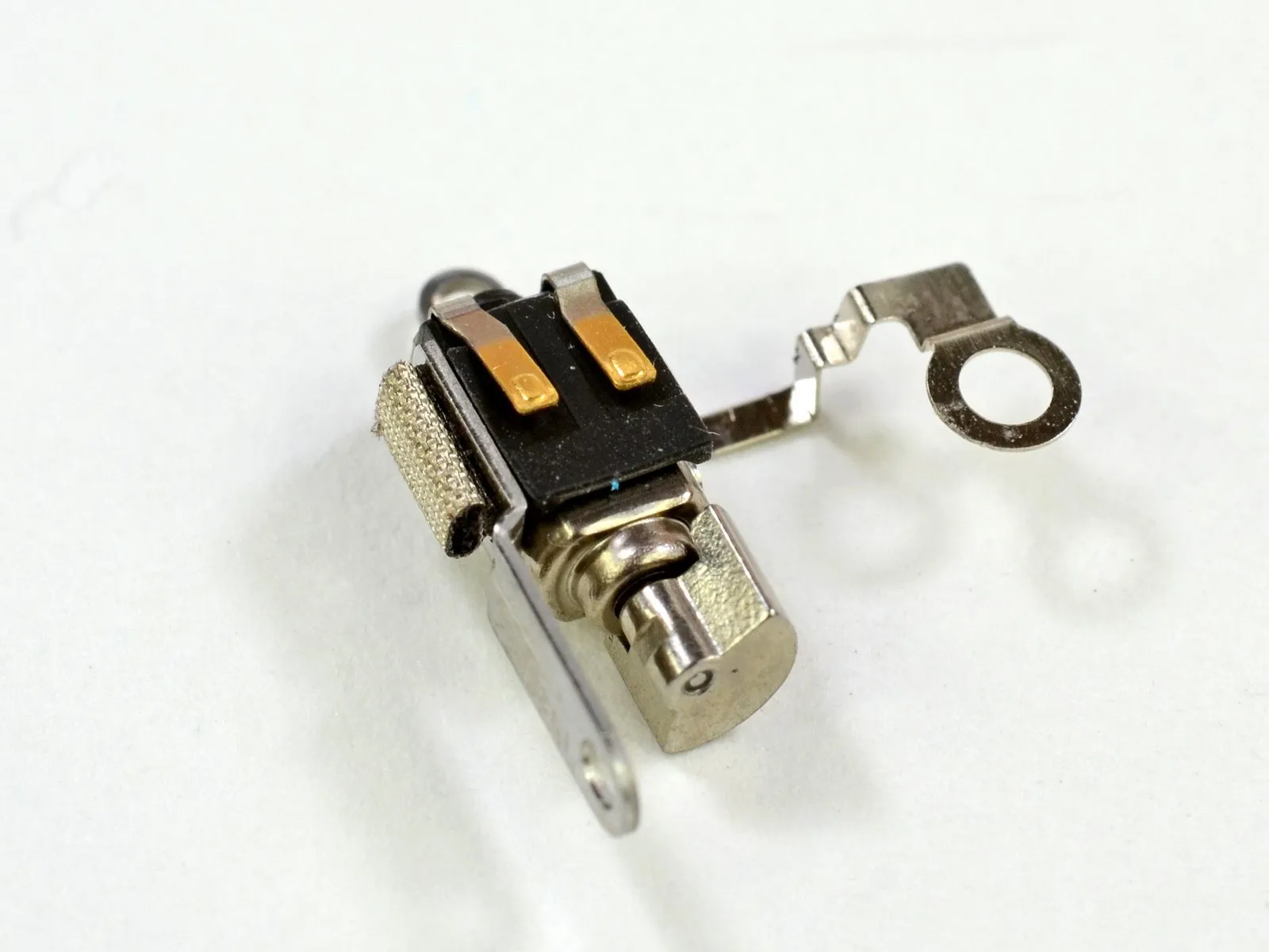
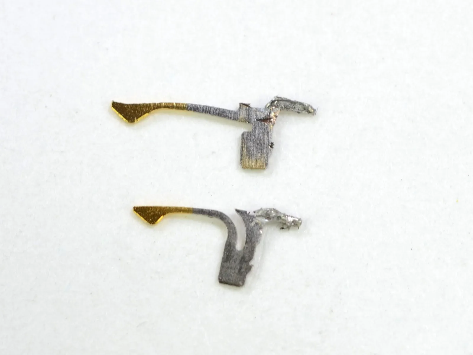
The vibrator motor utilizes pressure contacts, eliminating the need for soldering or connector disconnection during replacement.
The vibration mechanism in the iPhone 5 differs from that of the iPhone 4S; instead of a linear-oscillating vibrator, it utilizes a rotational motor incorporating a counterweight.
Previously, Apple’s selection of a linear oscillating vibrator, manufactured by Samsung, was lauded for its reduced noise and less disruptive operation; however, the rationale behind reverting to a different vibration system is currently unclear.
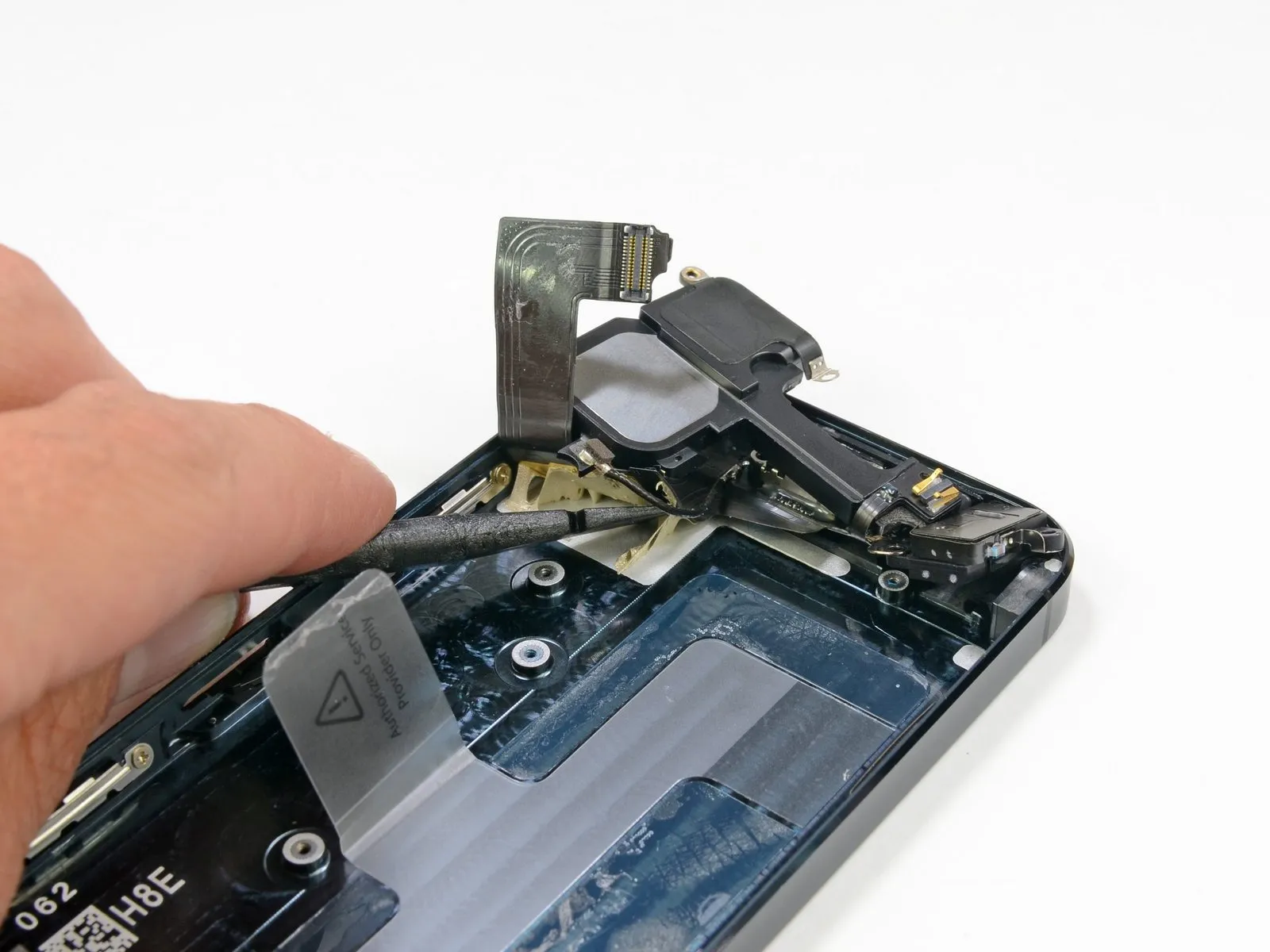
Step 27
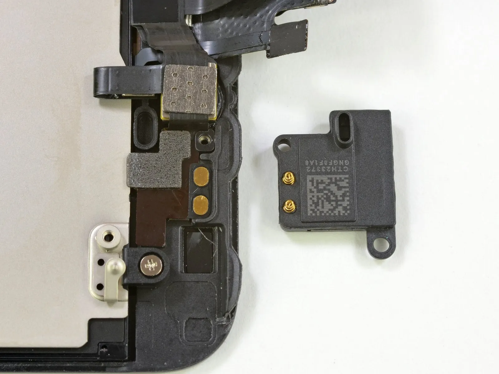
Two screws secure the ear speaker, allowing for straightforward removal, and it interfaces with the display assembly via spring contact connectors.
Due to its attachment to the delicate power button ribbon cable, separating the iPhone 4S speaker previously demanded considerable effort; the redesigned assembly now allows for straightforward speaker removal.
Step 28
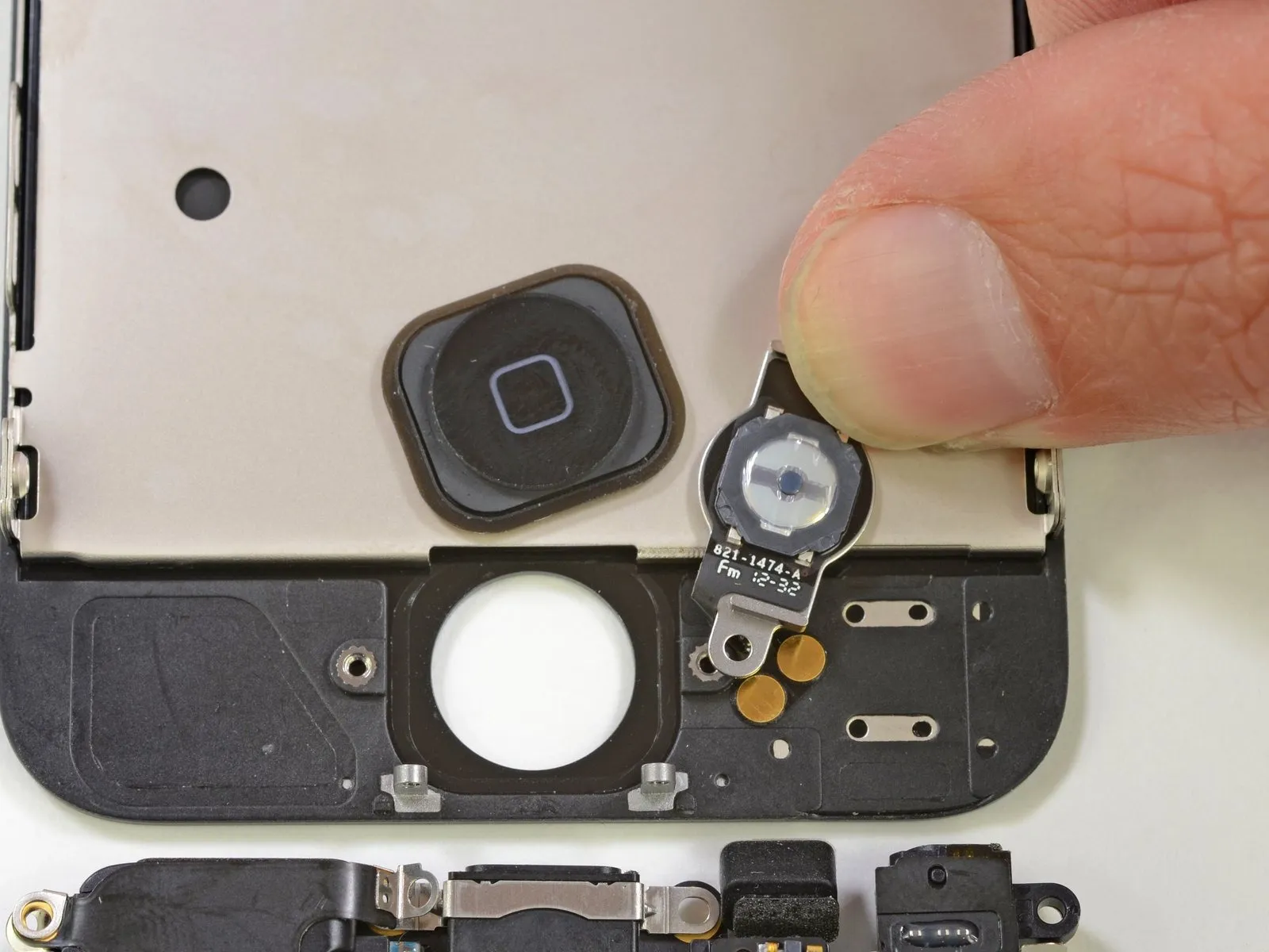
The redesigned home button in Apple's latest models incorporates a metal support bracket intended to enhance the durability of this frequently activated component.
A common problem for iPhone 4 and 4S owners involves a malfunctioning home button, often deterring users from attempting a fix; however, the redesigned replacement part aims to improve durability and simplify the repair process.
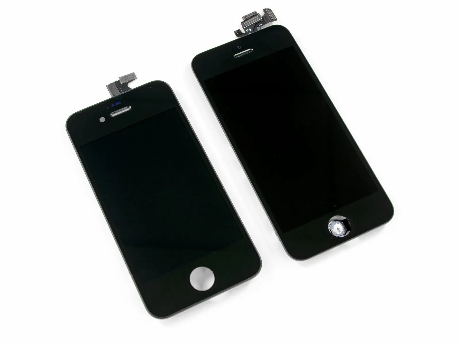
Examine the display assemblies of the iPhone 4 and iPhone 5 to note differences; the iPhone 4s model incorporates a built-in home button.
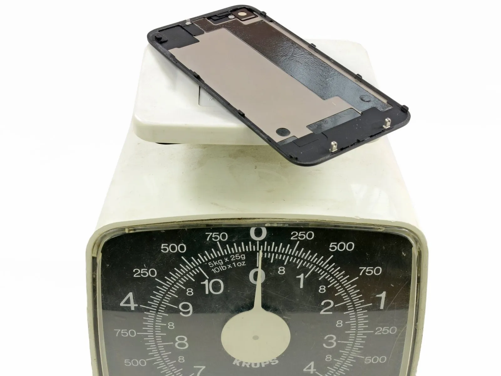
Step 29
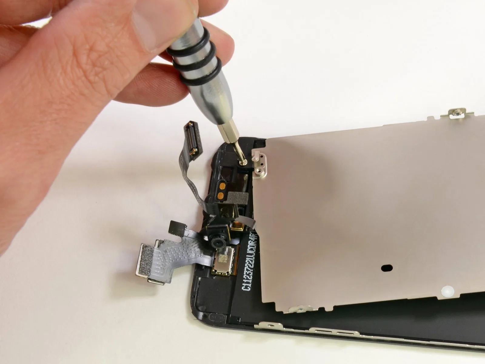
A small number of screws secure the component initially mistaken for the LCD assembly, allowing for its straightforward removal.
The component likely functions as a heat shield and provides a path for heat to escape. Its proximity to the screw and the presence of a spring contact indicate a potential grounding connection.
Contrary to some questions, this shield is not constructed from Liquidmetal; testing indicates its electrical resistance matches that of stainless steel, and it exhibits a slight magnetic property consistent with stainless steel.
Step 30
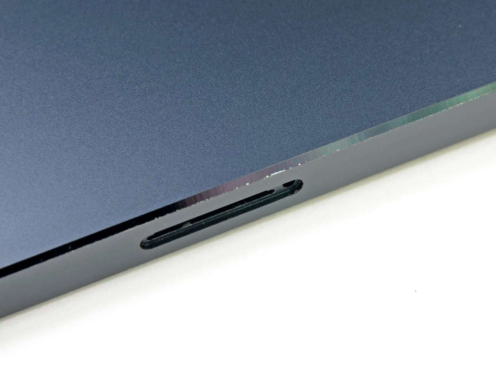
Responding to user feedback, we investigated reports regarding the premature wear of the black coating, commonly referred to as "Scuff Gate."
The lateral surface presents considerable rigidity; however, the beveled edge is prone to surface abrasion, which manifests as a reflective mark.
Exercise caution during this process, or utilize a protective case; alternatively, proceed without concern for potential damage.
Step 31
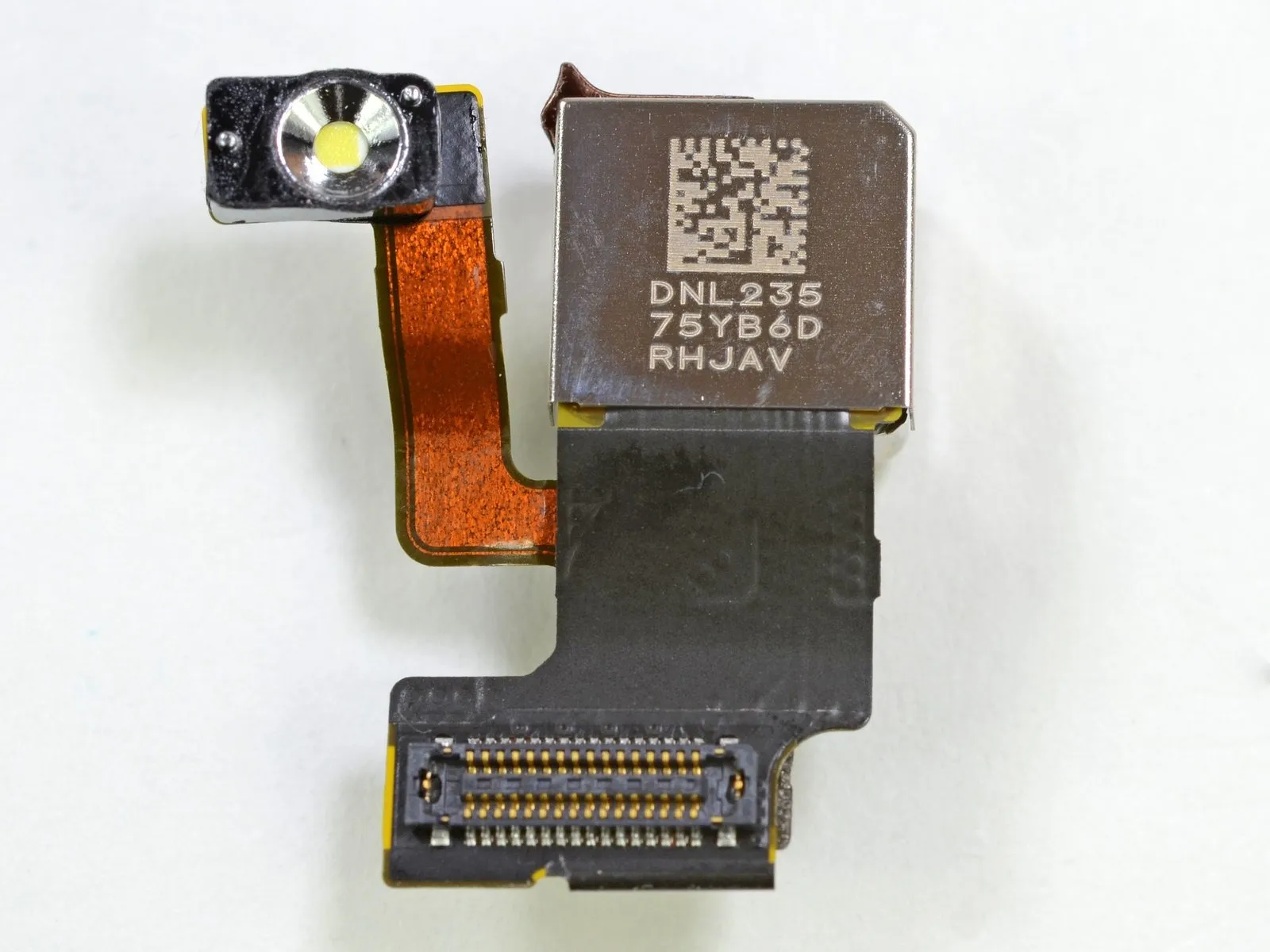
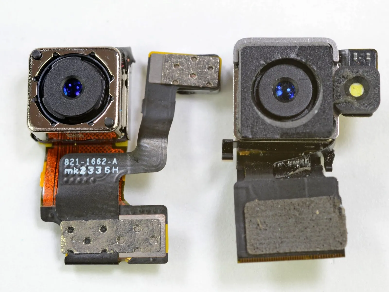
The iPhone 5 featured an 8-megapixel iSight camera, a key feature that benefited from substantial internal enhancements by Sony, resulting in improved performance in low-light conditions and a 40% reduction in image capture time, despite maintaining a similar external appearance to previous models.
The iPhone 5's camera module is located on the device's left-hand side.
The quality of the resulting images hinges on whether you direct the camera toward subjects other than meals.
Step 32
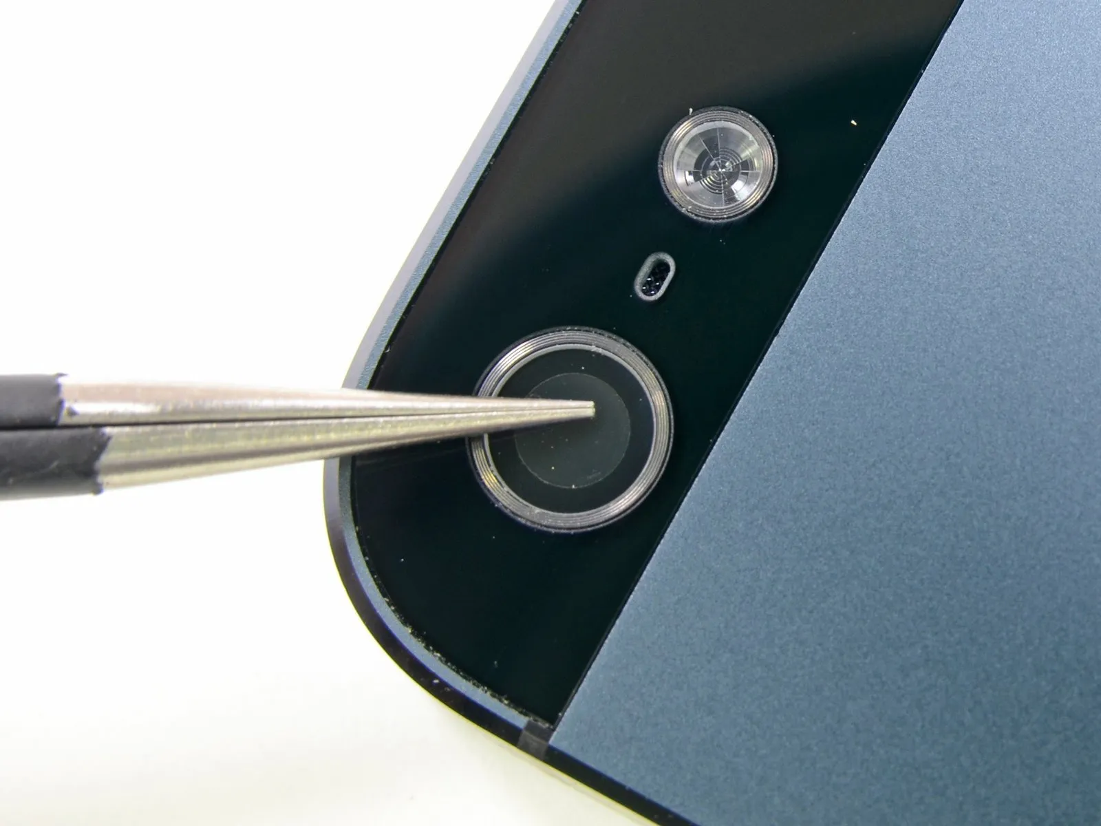
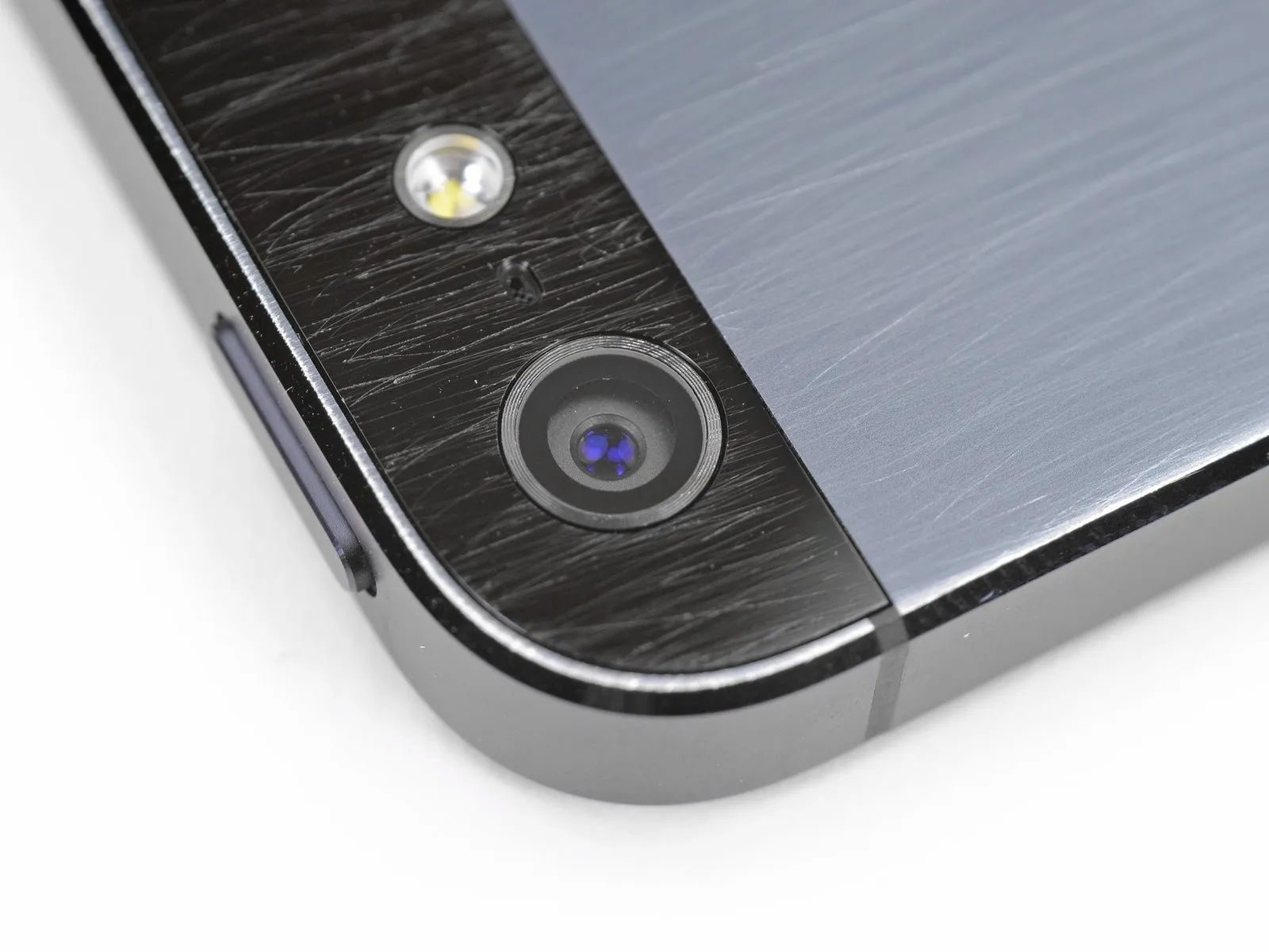
The camera's exterior lens cover utilizes a sapphire crystal, a material chosen by Apple for its exceptional hardness.
Using steel tweezers, we tested the surface of the transparent cover by attempting to scratch it; no scratches appeared on the lens. Although this test doesn't definitively prove the cover's composition is sapphire crystal, the results indicate a high degree of hardness and resistance to scratching.
To properly assess the camera lens coating's integrity, a more comprehensive evaluation is needed than a simple scratch test performed with tweezers; while the iPhone 5's rear case is susceptible to damage from abrasive materials like sandpaper and keys, the lens cover consistently demonstrates exceptional clarity.
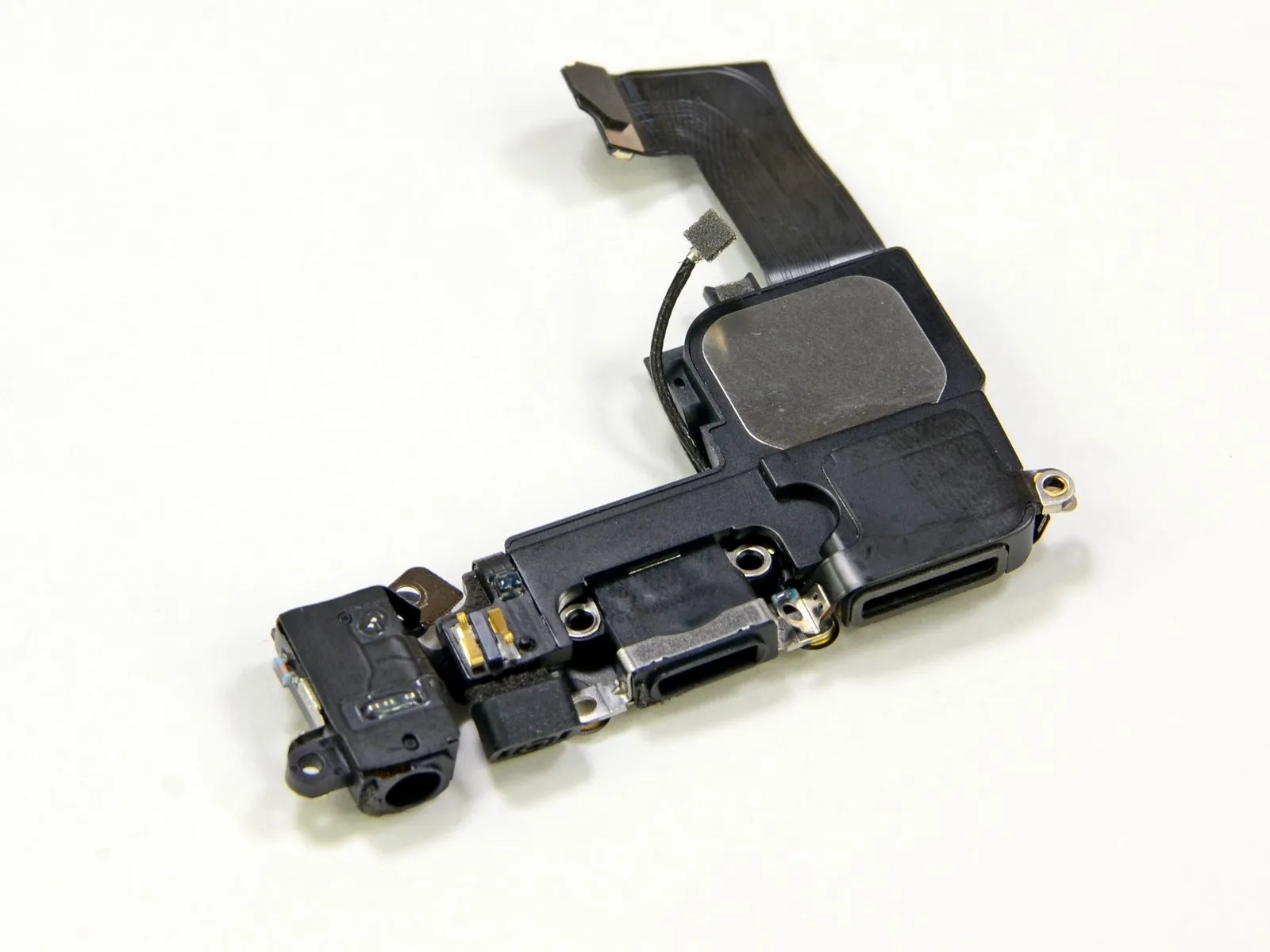
Step 33
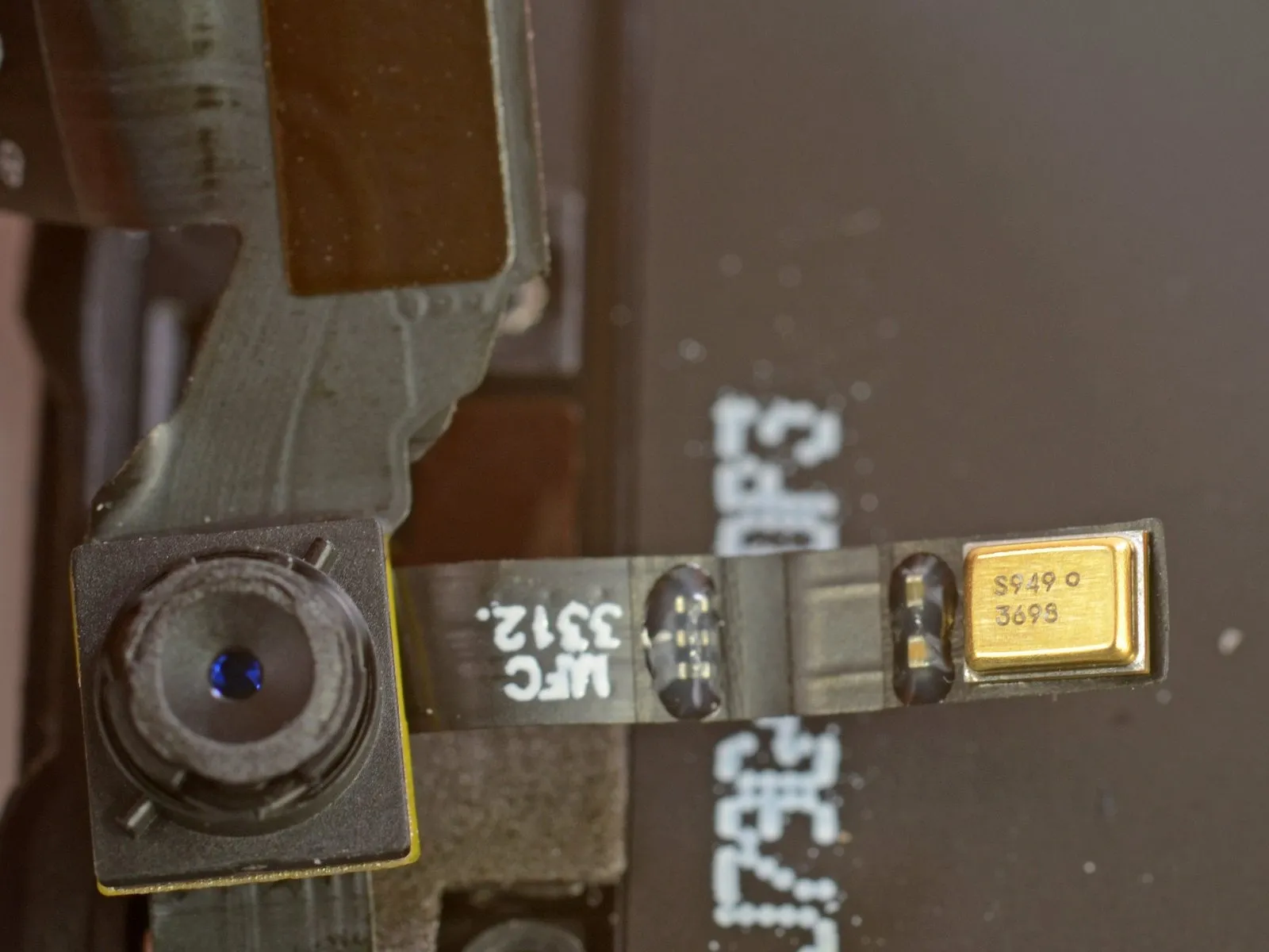
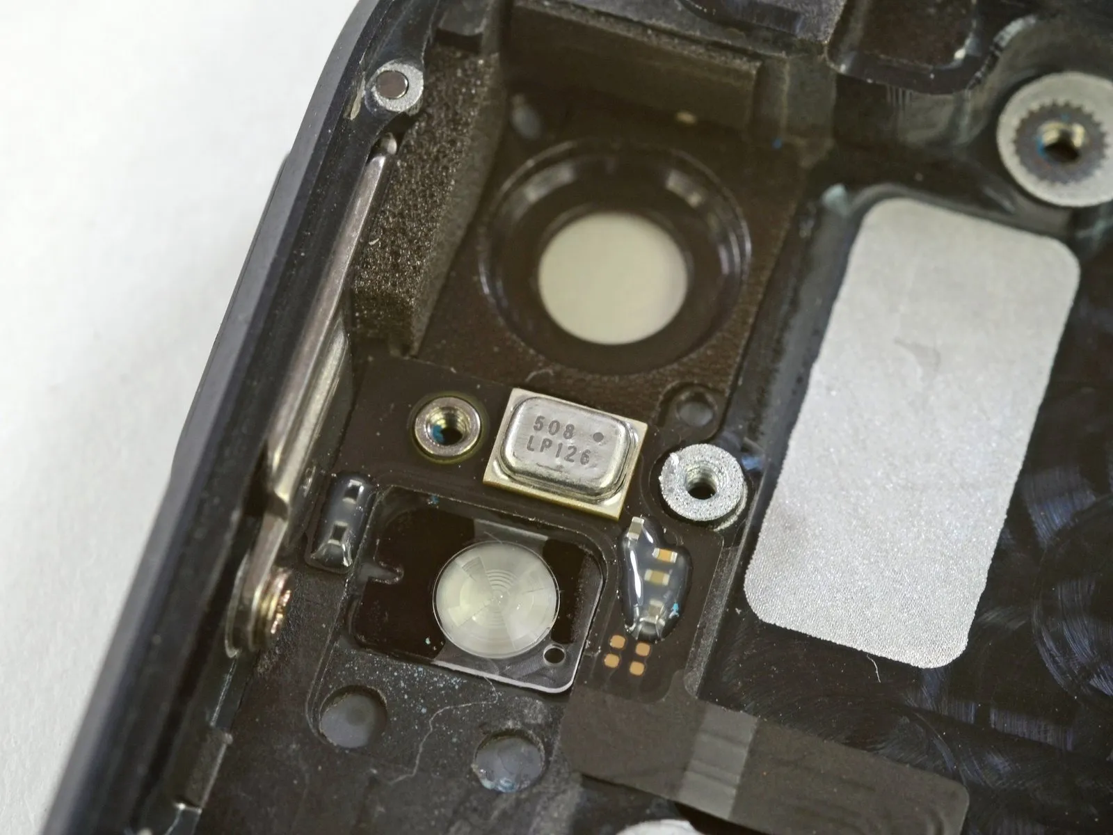
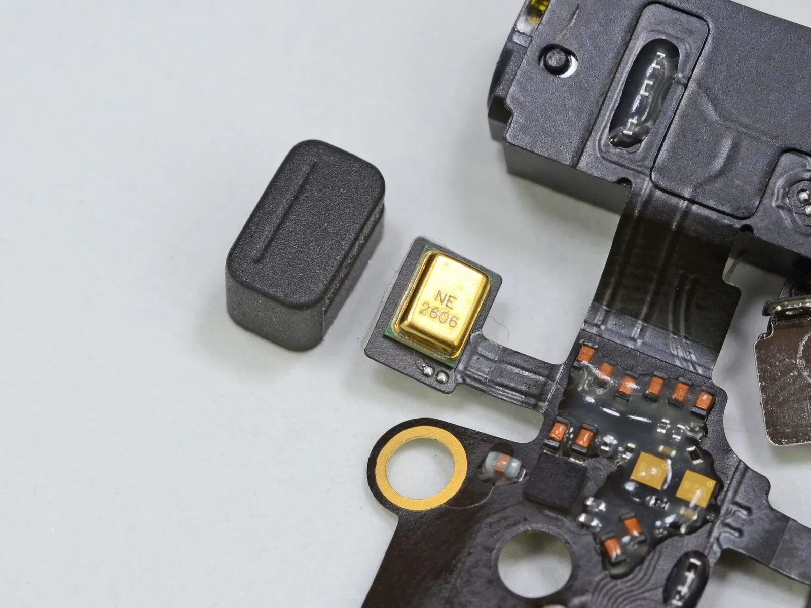
Apple incorporated multiple microphones into the device's upper portion, as initially stated. Locate the front-facing microphone, likely utilized for FaceTime and speakerphone functions. Observe that the rear section contains a triple microphone array; this microphone works in conjunction with the rear-facing camera to capture video and reduces background noise during phone calls.
Step 34

To assess the ease of fixing an iPhone 5, consider these factors: the adhesive securing the display and battery requires careful solvent application and patience; the five internal T3 Torx screws must be removed with a T3 Torx screwdriver; the logic board is adhered to the enclosure and necessitates heat to loosen; the front-facing camera cable is fragile and prone to damage; the battery connector is secured with a bracket requiring removal; and the rear case is bonded with adhesive, demanding heat and prying to separate, all while exercising caution to avoid damaging the LCD shield plate.Repair difficulty is rated as 7 on a scale of 10, with 10 representing the simplest possible repair.
- Because the front glass/display is most commonly damaged and therefore the initial component needing replacement on iPhone 5 repairs, it’s designed for relatively easy removal.
- After detaching the front panel, the battery can be released by gently applying separating force.
- Due to the presence of Pentalobe screws securing the exterior casing, accessing the internal components of an iPhone 5 presents a greater opening challenge.
- Because the front glass, digitizer, and LCD are integrated into a single assembly, replacing any one of these parts necessitates replacing the entire unit, which impacts repair expenses.
- Due to the numerous small components affixed to a single ribbon cable via soldering, replacing individual parts can significantly increase repair expenses.