iPhone 5s Bluetooth and Wi-Fi Antenna Replacement
If you're experiencing connectivity issues or a diminished wireless signal, proceed with troubleshooting.
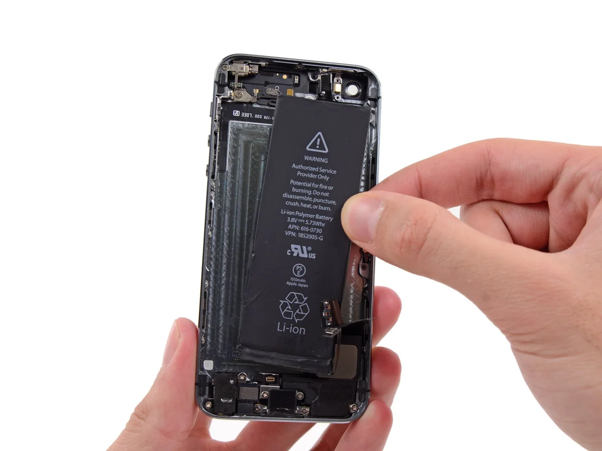
- The iPhone 5s's Wi-Fi and Bluetooth connectivity might require a replacement antenna.
Step 1 | Removing the Pentalobe screws

Begin by disconnecting the power supply, ensuring it is unplugged from the electrical outlet, then carefully remove the retaining screws—four in number—using a Phillips head screwdriver to access the internal components.To prevent potential fire or explosion hazards during repair, ensure the iPhone's lithium-ion battery is depleted to less than 25% capacity prior to beginning work; a fully charged battery poses a significant risk of ignition or rupture if damaged.
To prevent electrical shock or damage, ensure the iPhone is completely de-energized prior to starting the repair process.
Using a Pentalobe screwdriver, detach the two screws, each measuring 3.9 mm, located on the left and right sides of the Lightning connector.
To prevent electrical shock or damage, ensure the iPhone is completely de-energized prior to starting the repair process.
Using a Pentalobe screwdriver, detach the two screws, each measuring 3.9 mm, located on the left and right sides of the Lightning connector.
Step 2 | Taping the display glass


Using a 5/32-inch hex key, carefully tighten the retaining screw located on the motor assembly to a torque of 3.5 Nm, ensuring you do not overtighten and damage the threads.To mitigate the risk of additional shattering and potential injury while repairing a cracked display glass, secure the glass with tape.
Apply strips of transparent packing tape across the iPhone screen, ensuring complete coverage by slightly overlapping each successive strip.
To prevent scattered glass fragments and maintain stability during the display separation process, this technique is essential.
To safeguard your eyes from potential glass fragments released during the repair process, always use safety glasses.
Step 3 | Display separation prevention


Using a 5/32-inch hex key, carefully tighten the three retaining screws on the motor assembly to a torque of 3.5 inch-pounds, ensuring not to overtighten and potentially strip the threads.Carefully lift the display assembly—consisting of a glass screen, a plastic bezel, and integrated metal clips—from within the phone's chassis during the subsequent procedures.
Ensure complete removal of the display assembly, irrespective of the tool selected.
When the glass and plastic layers detach, mirroring the visual in the initial image, use a plastic opening tool to carefully insert it between the plastic frame and the phone's metal chassis, releasing the metal clips securing the case.
To ensure proper closure when reattaching a display bezel, apply a narrow adhesive strip positioned between the plastic bezel and the glass.
Step 4 | Anti-Clamp instructions


Using a 5/32-inch hex key, carefully tighten the retaining screw on the motor assembly to a torque of 3.5 Nm, ensuring the motor shaft remains aligned and avoiding damage to the threads; observe caution to prevent over-tightening.To simplify the opening process, the following two steps utilize the Anti-Clamp tool, a custom-designed aid; if you do not have this tool, proceed two steps further for an alternative procedure.
Refer to the included guide for detailed procedures regarding Anti-Clamp operation.
To release the Anti-Clamp's arms, move the blue handle in a rearward direction.
Position the arms so they extend across either the left or right side of the iPhone.
To secure the iPhone for repair, place a suction cup on the front surface, close to the lower edge and directly over the home button, and another suction cup on the rear, also near the bottom edge.
Apply vacuum by pressing the cups firmly against the surface you intend to work on.
To improve the Anti-Clamp's grip if the iPhone's exterior feels excessively smooth, apply the provided tape pad to enhance surface friction.
Step 5


Using a 5/32-inch hex key, carefully tighten the three retaining screws on the motor assembly to a torque of 3.5 inch-pounds, ensuring that the motor remains securely positioned and that no damage occurs to the threads; observe caution to prevent over-tightening.To secure the arms, advance the blue handle in its direction.
Rotate the handle fully, completing a 360-degree turn, observing for the initial signs of cup expansion.
Maintain proper alignment between the suction cups; should misalignment occur, gently release the suction cups' hold and reposition the arms.
Once sufficient space is created by the Anti-Clamp, slide a prying tool beneath the display.
To ensure adequate clearance, reposition the handle 90 degrees.
Apply adjustments in increments of no more than 90 degrees, pausing briefly after each adjustment to allow the Anti-Clamp device to function and the system to stabilize.
Step 6 | Manual Opening Procedure

Lacking an Anti-Clamp tool, secure the front panel with a single suction cup for lifting.
Position a suction cup directly on the display surface, situated slightly higher than the home button's location.
Ensure the screen's entire surface is covered by the cup to guarantee a secure connection.
Position a suction cup directly on the display surface, situated slightly higher than the home button's location.
Ensure the screen's entire surface is covered by the cup to guarantee a secure connection.
Step 7 | Start lifting the front panel assembly

Detach the front panel by releasing the retaining clips, then carefully separate the phone's housing just enough to access and disconnect the multiple ribbon cables; proceed with deliberate caution to prevent component damage.
Secure the suction cup directly onto the front panel assembly, positioning it close to the home button to ensure a strong hold.
Using one hand to secure the iPhone, lift the suction cup vertically to gently create a small gap between the front panel and the rear case, beginning at the home button area.
Using a plastic opening tool, carefully separate the rear case from the front panel assembly by gently levering the edges, simultaneously lifting with a suction cup.
Exercise caution and use steady, even pressure when installing the front panel assembly, as its fit is considerably snugger than what is typical for similar equipment.
Step 8


Disconnecting the front panel assembly from the rear case should be avoided; several fragile ribbon cables secure the two components together.
To detach the suction cup, depress the plastic projection to break the airtight seal.
Carefully detach the screen from the device using the suction cup.
To detach the suction cup, depress the plastic projection to break the airtight seal.
Carefully detach the screen from the device using the suction cup.
Step 9 | Removing the Touch ID cable bracket


Carefully separate the phone's casing to expose the metallic support securing the home button cable.
To prevent damage to the home button cable and its connector, avoid excessive separation of the phone's components; maintain slack in the cable, as overextension can cause harm.
To maintain Touch ID operation, replacement of the home button assembly requires using the original component; otherwise, a substitute part will only provide standard home button functionality, excluding Touch ID features.
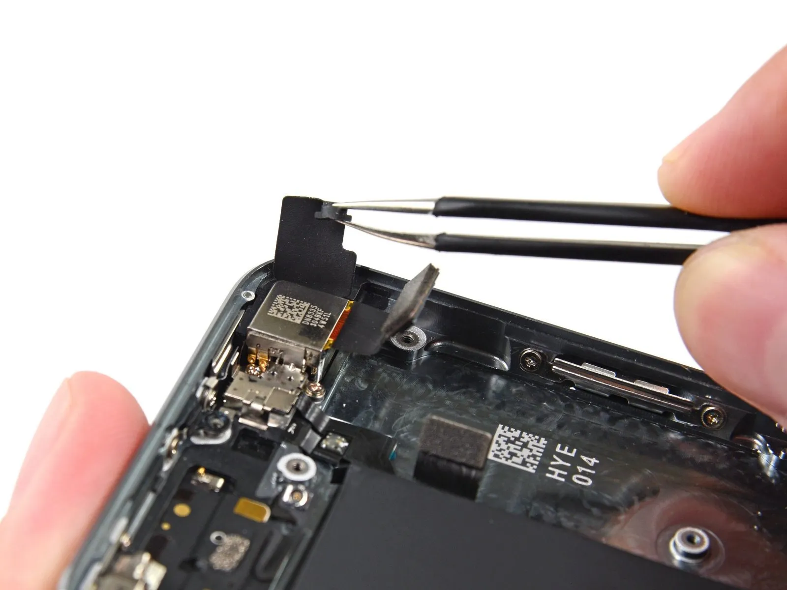
Carefully leverage the bracket loose using a spudger tip, then grasp and detach it with tweezers.
For reassembly procedures, proceed with the subsequent two instructions; otherwise, advance directly to Step 12.
To prevent damage to the home button cable and its connector, avoid excessive separation of the phone's components; maintain slack in the cable, as overextension can cause harm.
To maintain Touch ID operation, replacement of the home button assembly requires using the original component; otherwise, a substitute part will only provide standard home button functionality, excluding Touch ID features.
Carefully leverage the bracket loose using a spudger tip, then grasp and detach it with tweezers.
For reassembly procedures, proceed with the subsequent two instructions; otherwise, advance directly to Step 12.
Step 10


To complete reassembly, secure the Touch ID cable bracket by positioning its upper edge between the battery and the Touch ID cable connector, ensuring it sits ahead of the metal tab, then fasten the bracket's lower edge by engaging it with the connector.
Position the bracket's upper edge so it covers the Touch ID cable connector, then move it horizontally to the right.
Position the bracket so it covers the connector, ensuring the "leg" edge creates a small incline and the opposing edge sits between the cable connector and the battery's adjacent metal tab. Using a spudger, press gently downward on the bracket to secure both the rear and front clasps.
Step 11


Carefully position the Touch ID cable bracket's front section over the cable connector, then secure it by pressing downward with the spudger's flat end.
To ensure the bracket sits level against the surface, reposition it by sliding it back over the cable connector if it doesn't seat properly.
To ensure the bracket sits level against the surface, reposition it by sliding it back over the cable connector if it doesn't seat properly.
Step 12 | Disconnecting the home button cable connector


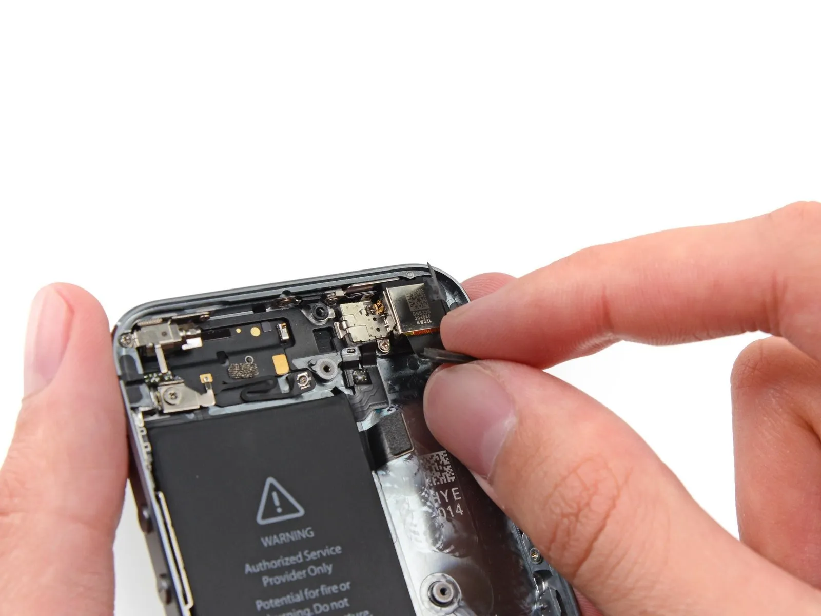
Carefully lift the home button cable connector from its socket using the pointed end of a spudger.
Avoid lifting the socket assembly; instead, detach the cable connector from its receptacle, as the socket is affixed to a separate, easily-damaged cable that can be dislodged with excessive force.
Avoid lifting the socket assembly; instead, detach the cable connector from its receptacle, as the socket is affixed to a separate, easily-damaged cable that can be dislodged with excessive force.
Step 13 | Opening up the phone


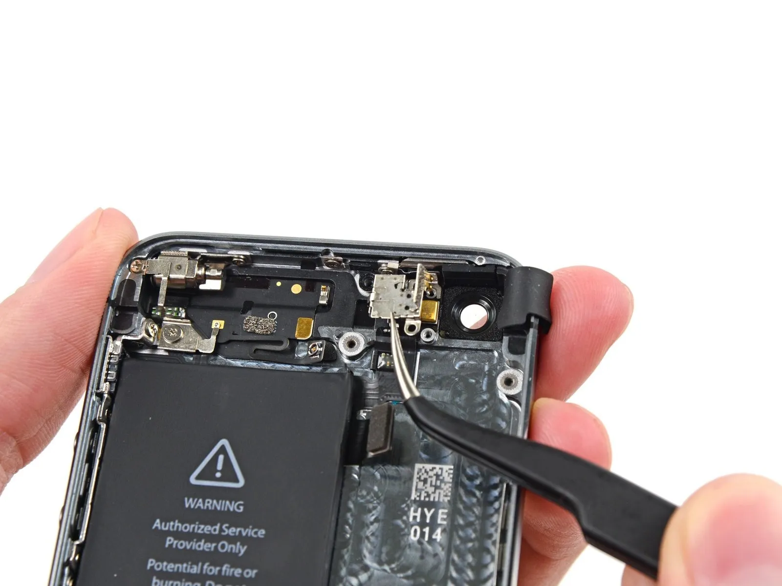
After disconnecting the connector, pivot the assembly, using the phone's upper edge as a fulcrum, to separate the home button end from the rear case.
Carefully position the display at a 90-degree angle, then secure it in an upright position using a support to prevent movement during the repair process.
To avoid stressing the display's wiring during the repair process, secure it with a rubber band.
As a temporary substitute, an unopened, sealed can of soda can be employed to support the display during the repair.
Step 14

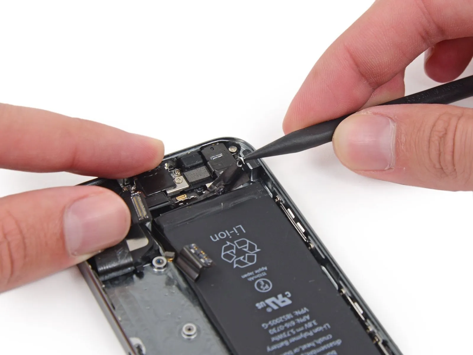
Using a Phillips #000 screwdriver, detach the metal battery connector bracket from the logic board by unscrewing the two 1.6 mm screws that hold it in place.
Step 15

Detach the bracket securing the battery connector using a Tri-Point Y000 screwdriver.
Step 16


Carefully lift the battery connector away from its corresponding socket on the logic board, employing the flat edge of a spudger to avoid damage.
Exercise extreme caution when releasing the battery connector, focusing solely on the connector itself to avoid lifting the logic board socket; applying force to the socket or the logic board could result in socket destruction or damage to adjacent components.
Exercise extreme caution when releasing the battery connector, focusing solely on the connector itself to avoid lifting the logic board socket; applying force to the socket or the logic board could result in socket destruction or damage to adjacent components.
Step 17

Detach the cable bracket that holds the front panel assembly wiring by unscrewing the screws listed below.
Carefully manage all screws during this stage to ensure correct reassembly; misplacing a 1.3 mm or 1.7 mm screw and using it in the bottom right hole will severely damage the logic board, preventing the device from powering on.
Avoid applying excessive force when tightening screws, and ensure they thread freely; if resistance is encountered during installation, verify that the correct screw size is being used.
- A Phillips screwdriver, size #000, is needed to remove a 1.7-millimeter screw.
- A Phillips head screw, size #000 and measuring 1.2 millimeters.
- A Phillips head screw, size #000 and measuring 1.3 millimeters.
- An additional screw, measuring 1.7 mm in width and utilizing a Phillips #000 head, is required.
Carefully manage all screws during this stage to ensure correct reassembly; misplacing a 1.3 mm or 1.7 mm screw and using it in the bottom right hole will severely damage the logic board, preventing the device from powering on.
Avoid applying excessive force when tightening screws, and ensure they thread freely; if resistance is encountered during installation, verify that the correct screw size is being used.
Step 18

Detach the bracket securing the front panel assembly cable to the logic board.
Step 19


Carefully detach the front camera and sensor cable assembly from its connector using a spudger or similar non-conductive tool.
Step 20


Prior to either detaching or reattaching the cable in this procedure, ensure the battery is disconnected.
Carefully detach the LCD cable connector.
Should the LCD cable detach from its connector during reassembly, powering on the device might display white lines or a completely blank screen; to resolve this, re-establish the cable's connection and restart the phone, ideally by disconnecting and reconnecting the battery to ensure a complete power cycle.
Step 21


Carefully detach the digitizer cable connector.
Step 22

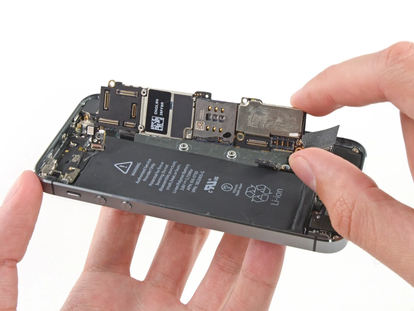
Detach the front panel assembly from the rear case.
Step 23 | SIM Card
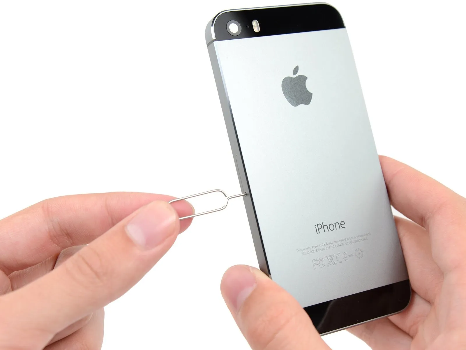
Use a SIM card eject tool, or carefully straighten a paperclip to insert it into the SIM card tray's tiny aperture to release the tray.
Apply substantial pressure until the tray releases.
Apply substantial pressure until the tray releases.
Step 24
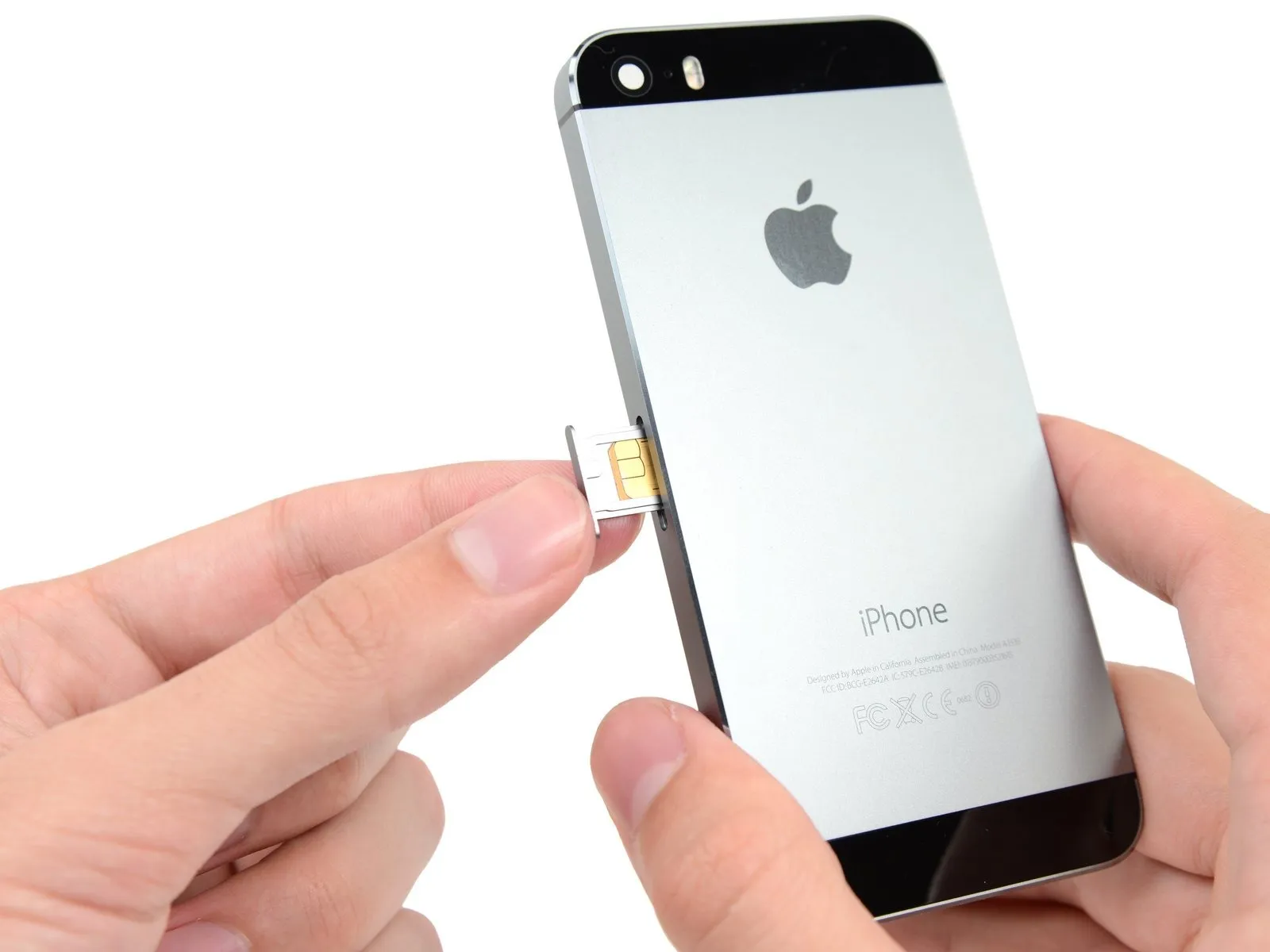
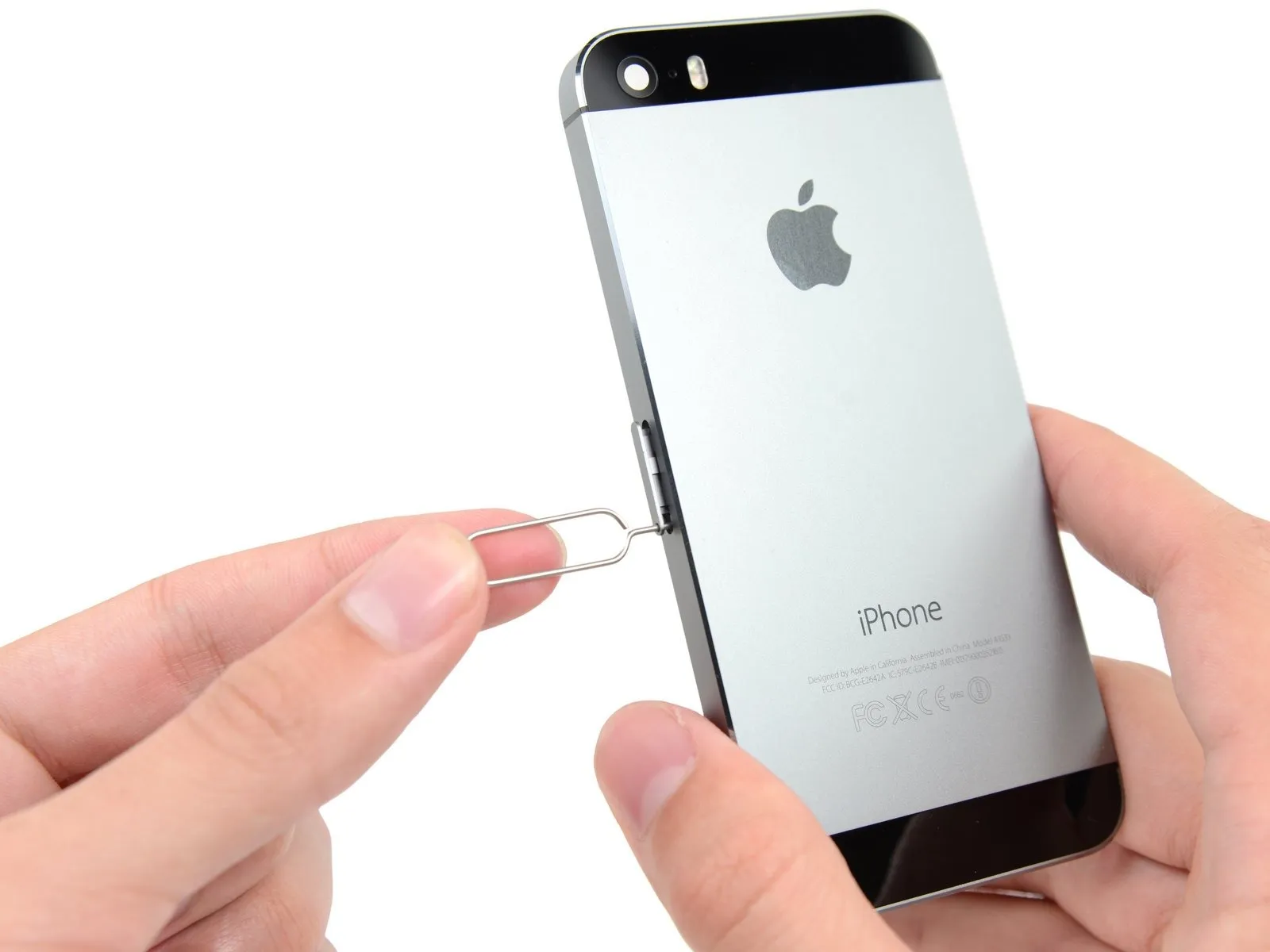
Using the SIM ejection tool or a similar small, sturdy item, carefully depress the SIM tray release button located on the device's side to release the SIM Card tray assembly and then gently pull the tray out.
Confirm the SIM card's alignment with the tray before sliding it back in.
Confirm the SIM card's alignment with the tray before sliding it back in.
Step 25 | Logic Board


Carefully lift the button assembly cable from its connection on the logic board using a spudger, applying gentle force.
Exercise extreme caution during the lifting process, ensuring force is applied solely to the connector itself, as applying pressure to the logic board socket risks irreversible damage to the connector.
Exercise extreme caution during the lifting process, ensuring force is applied solely to the connector itself, as applying pressure to the logic board socket risks irreversible damage to the connector.
Step 26


- Carefully leverage a spudger to disengage the Lightning connector cable from its corresponding socket on the logic board.
Carefully maneuver the Lightning connector cable so it doesn't obstruct access to the logic board.
Step 27


- Carefully lift the antenna cable from its connection on the logic board using the pointed end of a spudger.
Step 28


- Employing the flat spudger tip, carefully separate the connector securing the rear camera cable to its corresponding socket on the logic board.
Step 29

- Carefully detach any masking tape securing the camera flash bracket.
Step 30

- Using the appropriate screwdriver, detach the logic board by unscrewing all listed screws.
A Phillips head screwdriver, size #000, is needed to remove a 2.4-millimeter screw.
The logic board's metal contact, secured by this screw and a plastic bracket, may require removal following the procedure detailed in this step if it becomes loose.
Use two Phillips head screws, size #000 and 2.3 millimeters in length.
Use three screws, each measuring 2.8 millimeters in diameter.
A 2.9-millimeter standoff screw, constructed from a non-magnetic material, is required.
To detach standoff screws, utilize a standoff screwdriver or a compatible bit.
If a dedicated tool is unavailable, a small flathead screwdriver can be carefully employed; however, exercise heightened awareness to prevent slippage and potential harm to nearby parts.
Step 31


Carefully pry the logic board upward using a plastic opening tool, ensuring you can then grip it with your fingers.
Step 32


Carefully move the logic board outward, creating a small gap between it and the rear-facing camera assembly.
Avoid detaching the logic board at this stage; it remains secured by an antenna cable located on the rear of the device.
Carefully rotate the logic board so that it faces the battery, mimicking the action of turning a page.
Avoid detaching the logic board at this stage; it remains secured by an antenna cable located on the rear of the device.
Carefully rotate the logic board so that it faces the battery, mimicking the action of turning a page.
Step 33


Employing the flat spudger tip, carefully separate the antenna cable connector from the logic board's rear surface.
Carefully detach the iPhone's logic board.
Carefully detach the iPhone's logic board.
Step 34


The metal plate situated close to the rear camera is currently detached and risks complete separation from its designated housing.
To prevent loss of the tiny plate, detach it and keep it in a safe location during the repair process.
Carefully detach the plate located under the bracket on the left side of the rear camera using tweezers.
Ensure the plate is positioned so its smaller projection aligns to the right side and its greatest flat surface contacts the phone's upper surface during reassembly.
Step 35 | Rear Facing Camera


Carefully use tweezers to pivot the rubber camera cover away from its retaining clip and outward, toward the rear case exterior.
This cover remains fixed to the rear case; avoid complete detachment, instead, carefully pivot it open.
This cover remains fixed to the rear case; avoid complete detachment, instead, carefully pivot it open.
Step 36


Carefully align the 4mm diameter dowel pins with their corresponding holes in both the upper and lower chassis halves, then gently press the two sections together until fully seated, ensuring no gaps remain and the assembly is flush.Carefully detach the rear case to free the rear-facing camera.
To ensure proper connection during reassembly, route the camera cable into its designated position behind the logic board, forming a 'U' bend.
To ensure proper device function and prevent damage, substitute a displaced rubber camera bumper with a new one prior to reassembly.
To ensure proper connection during reassembly, route the camera cable into its designated position behind the logic board, forming a 'U' bend.
To ensure proper device function and prevent damage, substitute a displaced rubber camera bumper with a new one prior to reassembly.
Step 37 | Camera Bracket

Using a 5/32-inch hex key, carefully tighten the four M4x8mm screws securing the fan assembly to the heatsink, ensuring a torque of 4.5 in-lbs to prevent damage.Using a Phillips #000 screwdriver, detach the rear camera bracket by unscrewing the two 1.6 mm screws that hold it in place.
Step 38
Using a 5/32-inch hex key, carefully tighten the three retaining screws on the motor assembly to a torque of 3.5 inch-pounds, ensuring that you do not overtighten and damage the threads.Detach the bracket securing the rear camera assembly from the back of the device enclosure.
Step 39
Carefully align the 4mm hex key to the setscrew on the motor shaft, ensuring the shaft remains stationary, and tighten the setscrew to a torque of 6 in-lbs using the hex key.Carefully detach the rubber bumper, which protects the camera body, from the case.
Step 40 | Battery

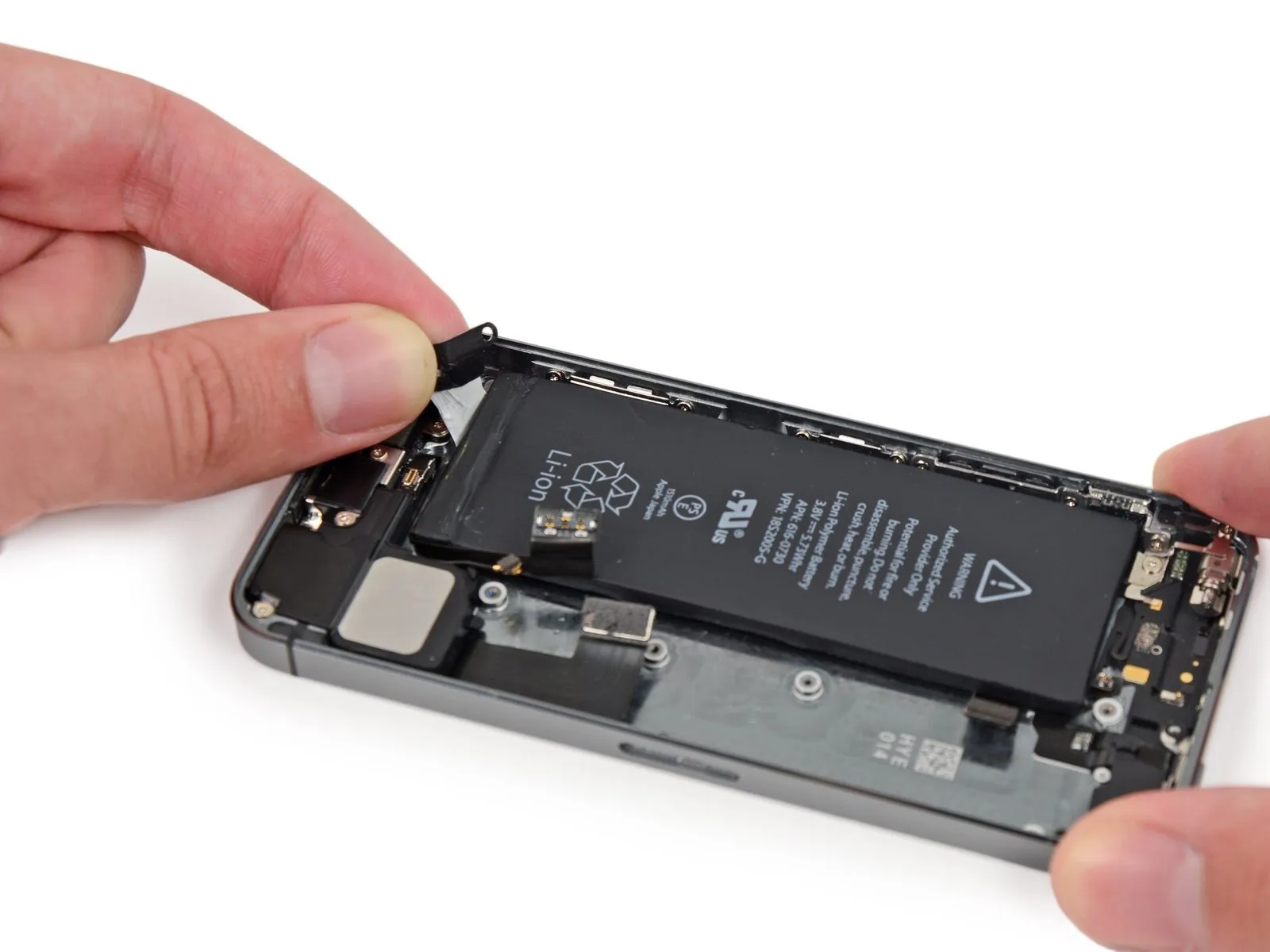
Carefully align the 4mm hex key to the setscrew, ensuring it engages fully, then gradually tighten the setscrew to a torque of 1.5 Nm using the torque wrench.Using a spudger, gently lift the battery adhesive tab by inserting the tool's tip into the opening located close to the headphone jack.
Gently raise the tab a small amount, then use the spudger to carefully release it from its housing.
Gently raise the tab a small amount, then use the spudger to carefully release it from its housing.
Step 41


Carefully detach the battery adhesive by lifting the adhesive tab vertically.
Using a sharp blade, sever the black battery adhesive tab by slicing through the two white adhesive strips that hold it in place, thus detaching the tab.
Using a sharp blade, sever the black battery adhesive tab by slicing through the two white adhesive strips that hold it in place, thus detaching the tab.
Step 42

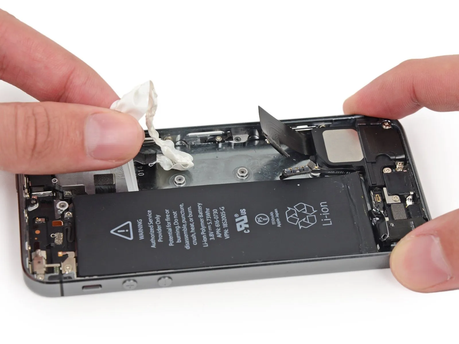
To ensure proper removal, maintain the strips' flatness and avoid creases, as folds can cause them to adhere and tear rather than detach smoothly.
Gently peel one battery adhesive tab downwards, moving it towards the iPhone's lower edge.
To detach the strip, apply consistent, even force while guiding it out from the space between the battery and the rear case; ensure the pulling angle remains at 60 degrees or less to optimize the release.
Gently peel one battery adhesive tab downwards, moving it towards the iPhone's lower edge.
To detach the strip, apply consistent, even force while guiding it out from the space between the battery and the rear case; ensure the pulling angle remains at 60 degrees or less to optimize the release.
Step 43

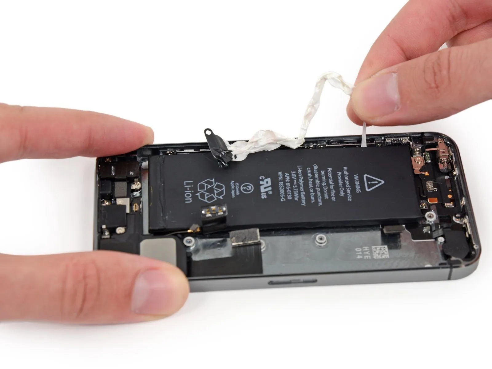
Maneuver the strip along the corner's contour and vertically up the battery's surface, exercising caution.
Exercise caution to prevent the flexible cable from catching on the battery's edge or any other internal iPhone parts.
To release the strip completely, exert continuous tension, which will cause it to extend significantly beyond its initial size; reposition your grip closer to the battery as needed to maintain pulling force until the entire component detaches.
Step 44

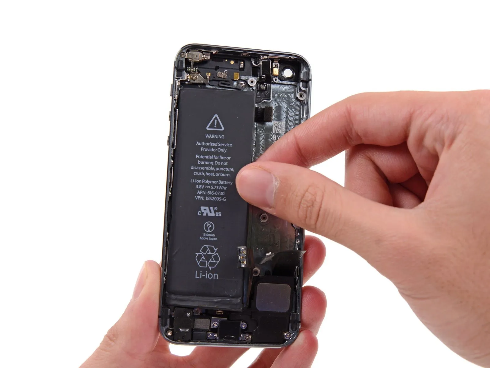
Employ the same procedure to detach the remaining adhesive strip.
Having detached both strips completely, proceed to a later stage of the repair.
Should the battery adhesive strips tear or become inaccessible during removal, carefully detach any remaining portions before continuing.
Having detached both strips completely, proceed to a later stage of the repair.
Should the battery adhesive strips tear or become inaccessible during removal, carefully detach any remaining portions before continuing.
Step 45

To free a battery adhered to the rear case after adhesive strip failure, apply heat using an iOpener or a hair dryer, focusing the warmth on the case's area immediately behind the battery.
Step 46

- Carefully turn the iPhone so the screen faces down, then slide a plastic card into the space between the battery’s casing and the phone’s rear enclosure.
To prevent battery damage and potential release of hazardous chemicals, ensure the card remains perfectly level throughout handling.
Advance the card until the adhesive securing the battery is released.
Step 47
- Disconnecting the power source, carefully take out the battery that is located within the rear case.
To ensure proper battery installation, follow these instructions to substitute the adhesive strips that secure the battery.
Step 48 | Vibrator

Using a Phillips #000 screwdriver, detach the screws securing the vibrator bracket.
- A screw with a 1.7 mm head diameter is required.
- A screw with a 2.5 mm diameter is required.
Step 49
Using tweezers, detach the vibrator bracket.
Step 50
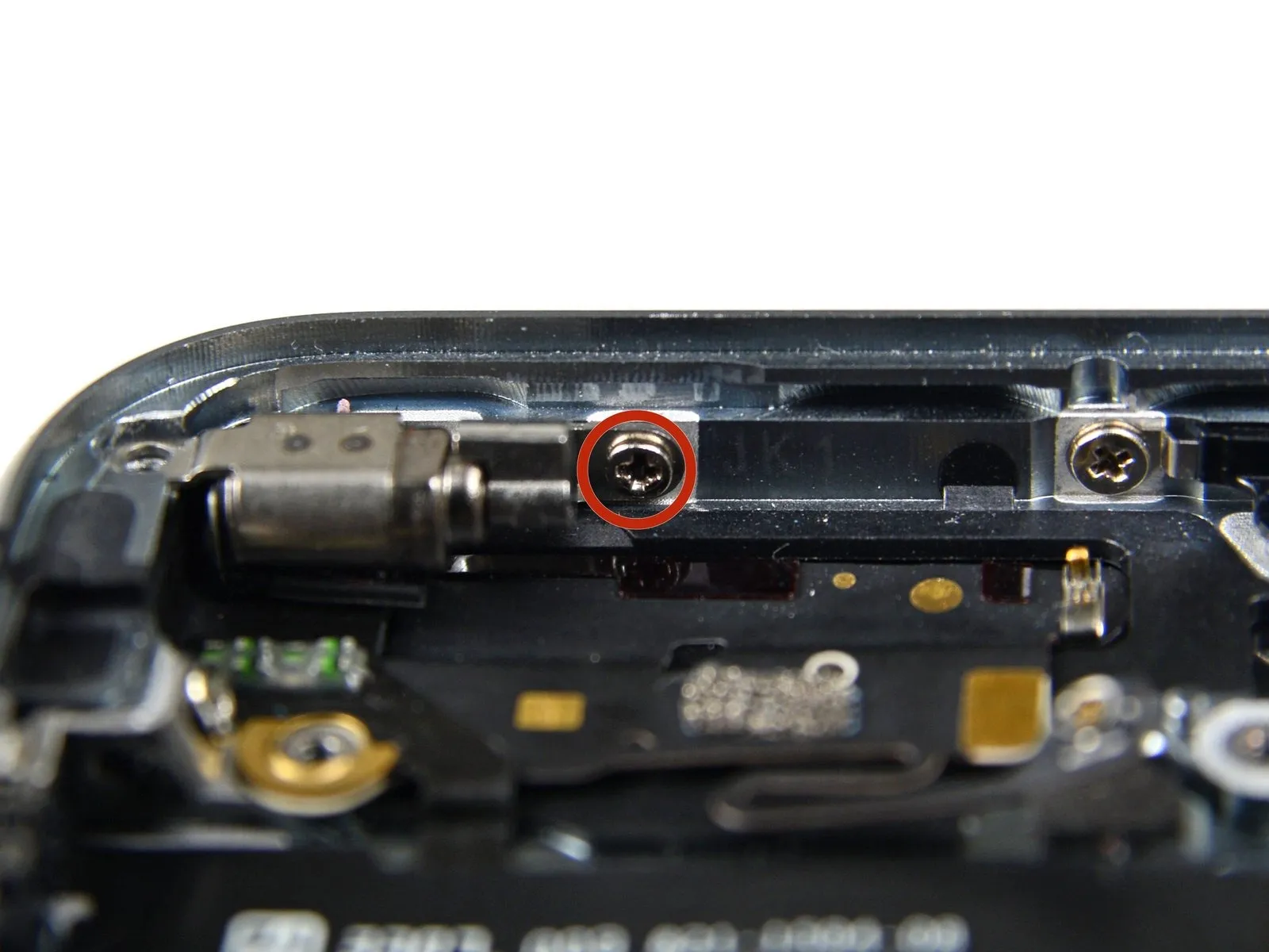
Using a Phillips #000 screwdriver, detach the vibrator from the rear case by unscrewing the 1.7 mm screw that holds it in place.
Step 51
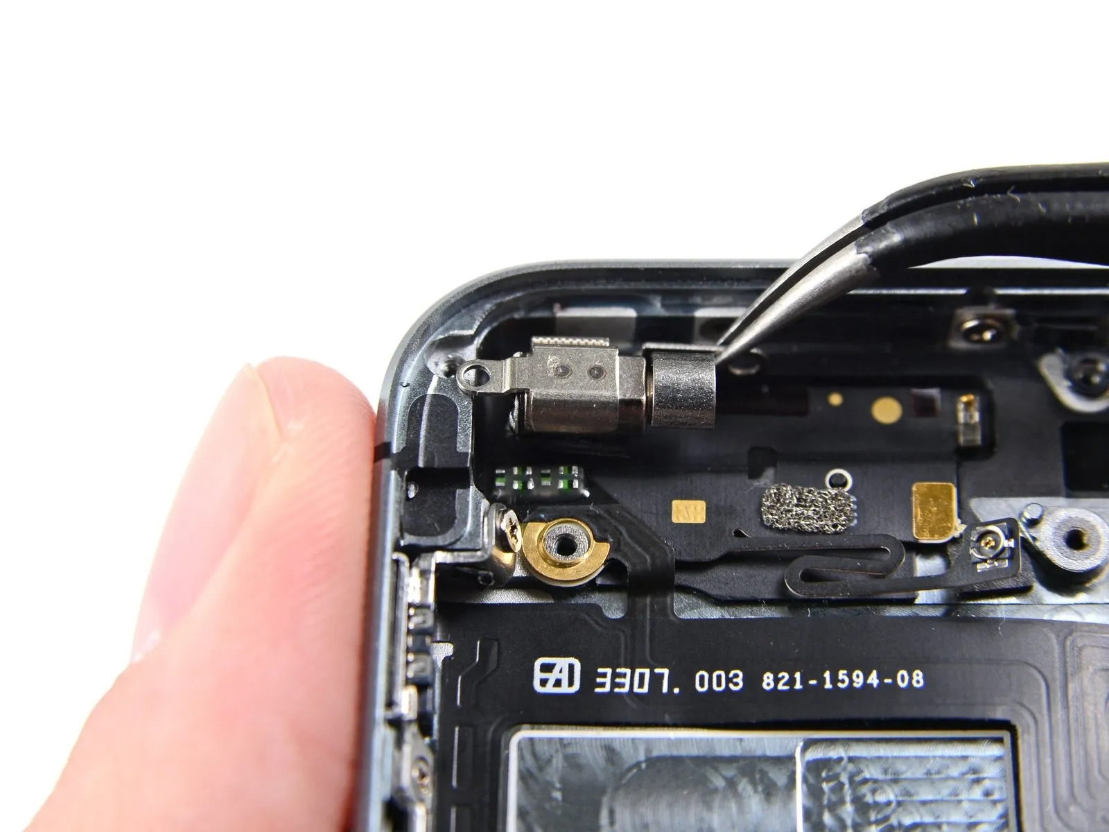
Carefully extract the vibrator from the rear case using tweezers.
Step 52 | Bluetooth and Wi-Fi Antenna

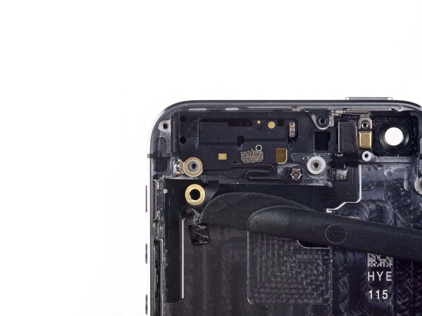
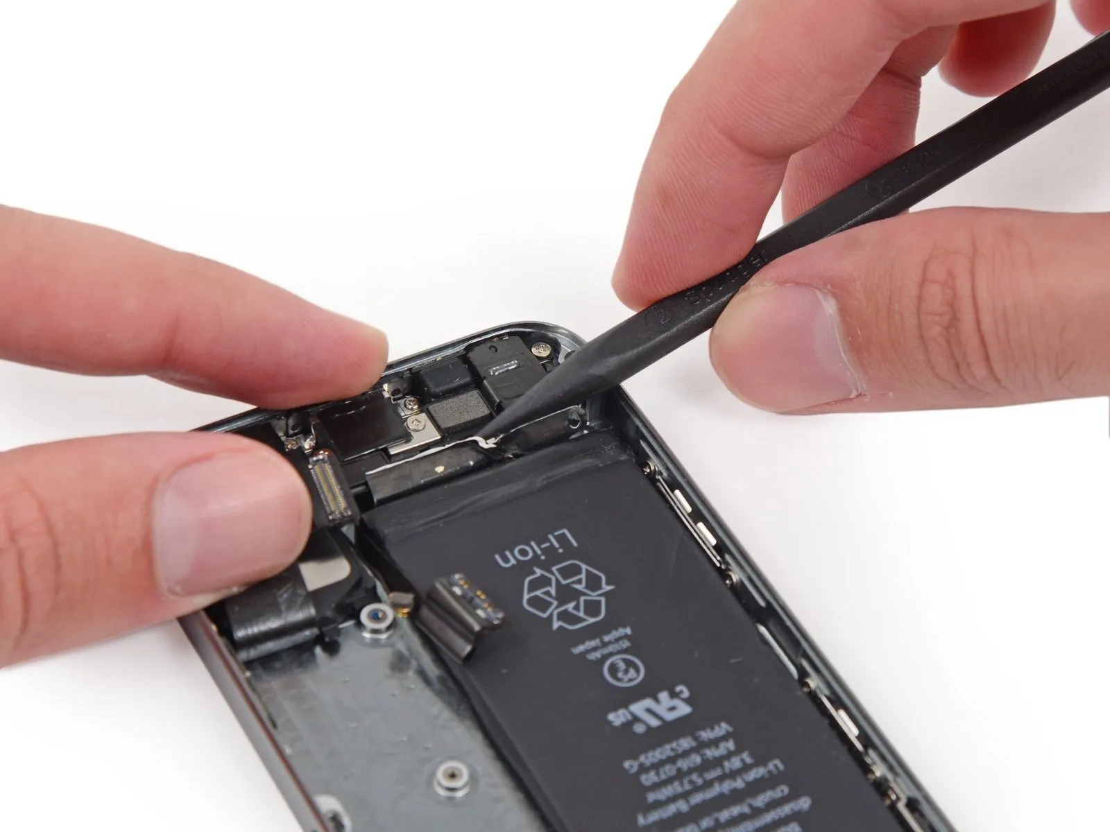
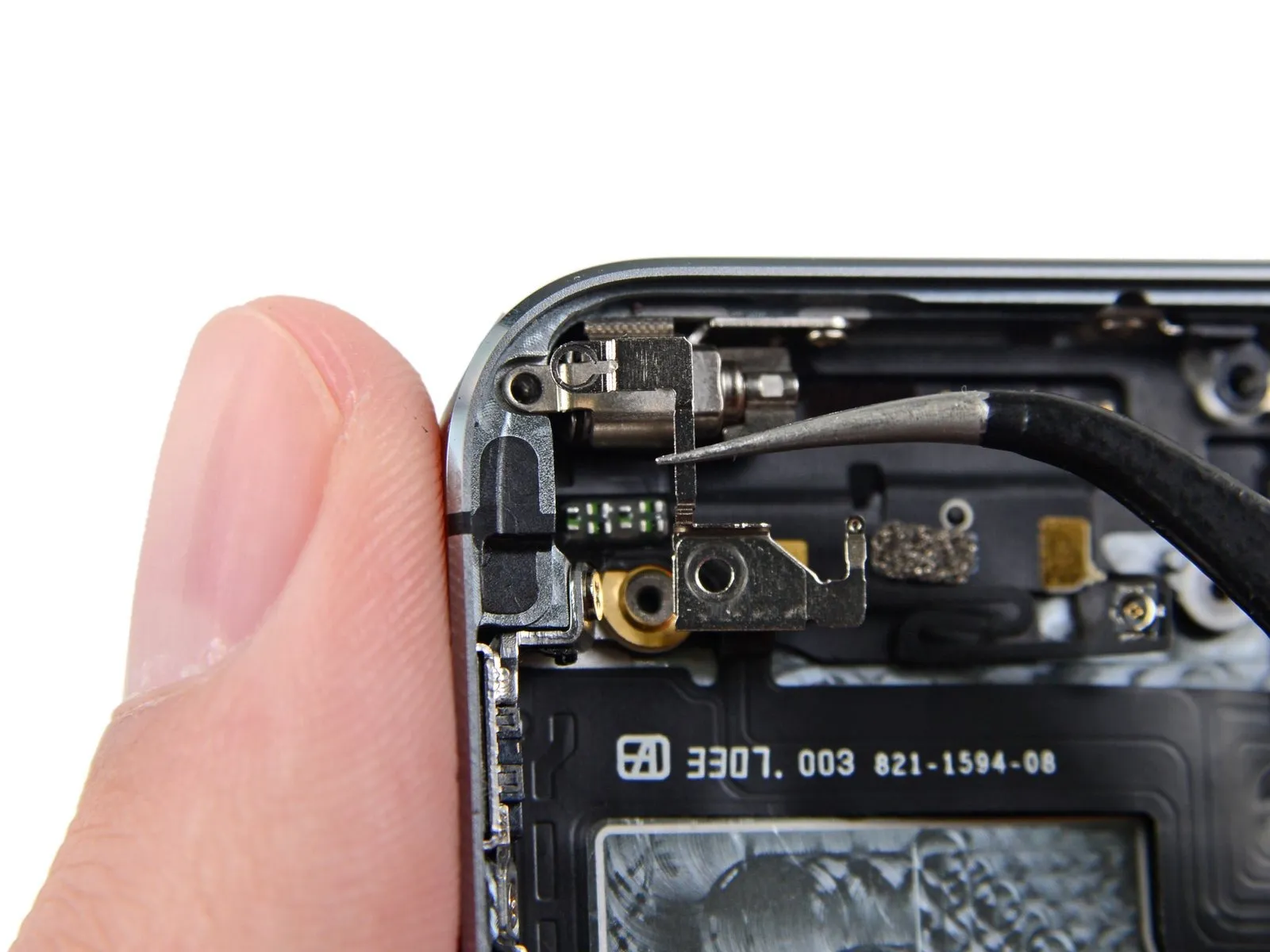
Carefully separate the vibrator contact pad, which is part of the upper cable assembly, from the Bluetooth and Wi-Fi antenna.
Damage to this cable can impair the vibrator and other upper component connections, resulting in loss of functionality.
Damage to this cable can impair the vibrator and other upper component connections, resulting in loss of functionality.
Step 53
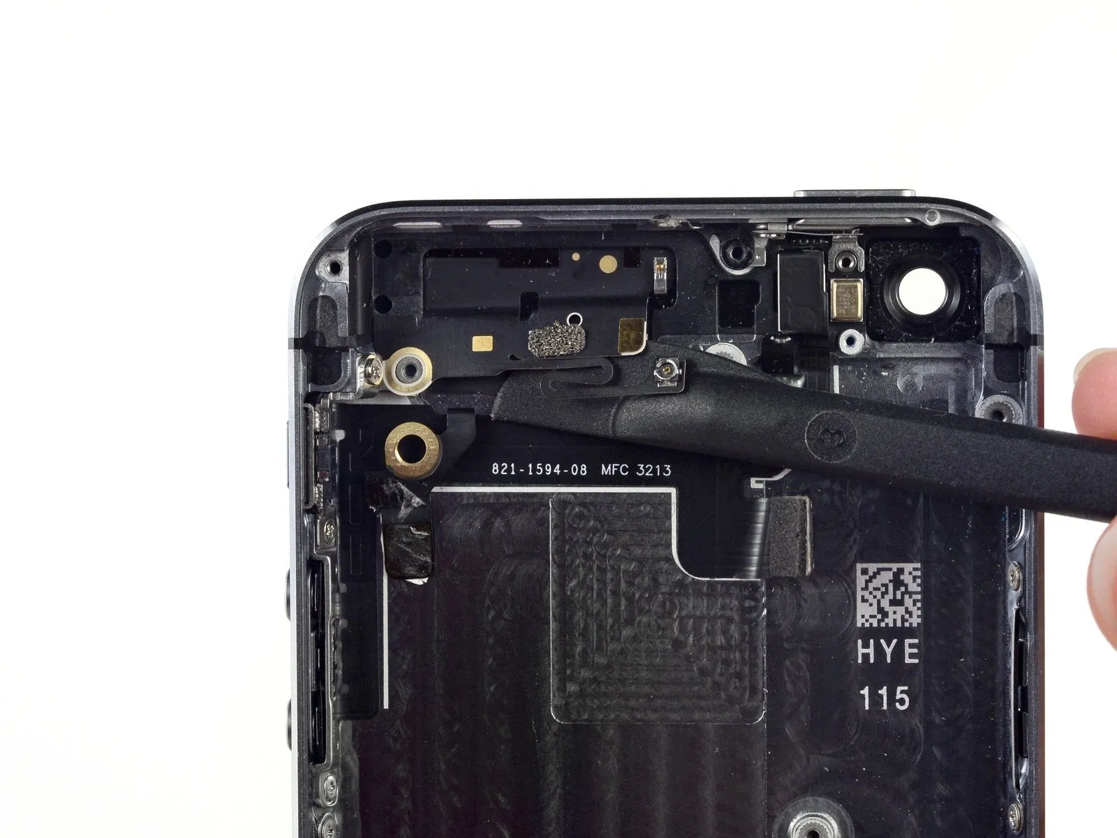
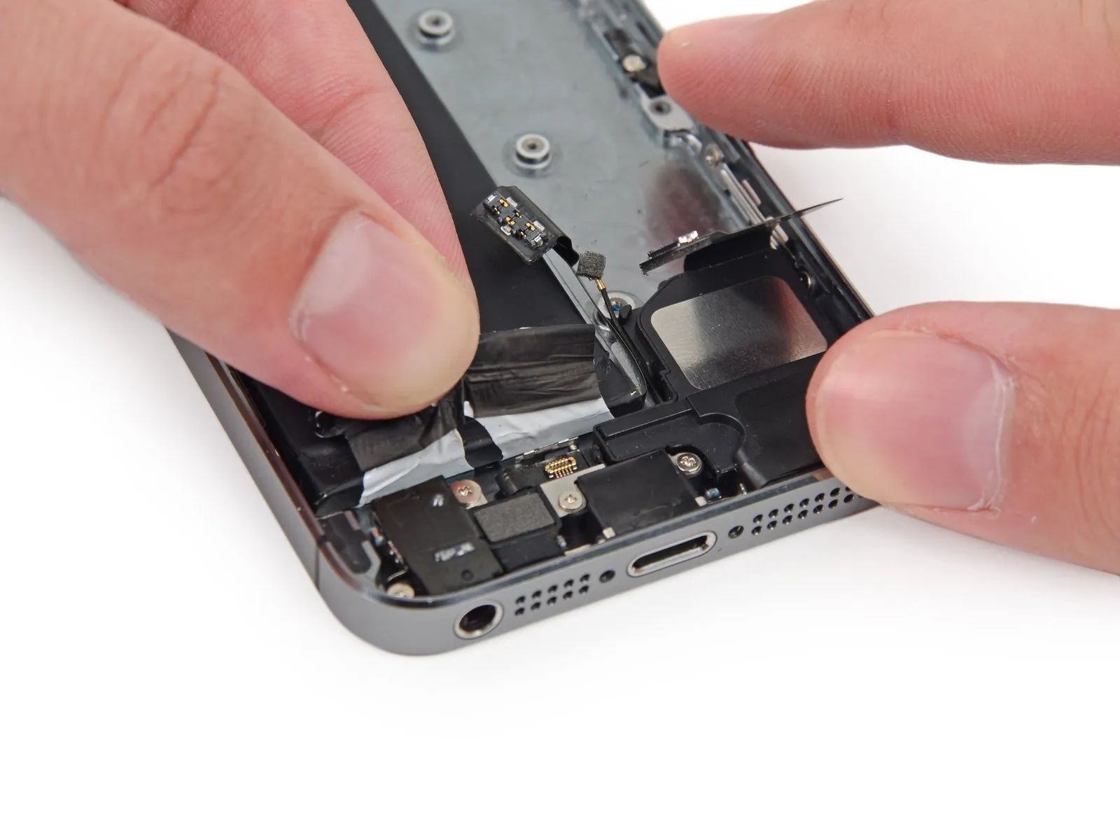
Using gentle force, detach the Bluetooth and Wi-Fi antenna from the rear case by releasing it from the adhesive.
Step 54

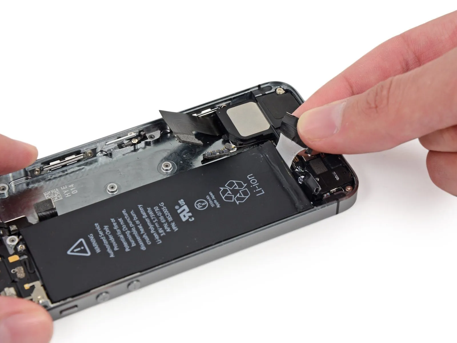
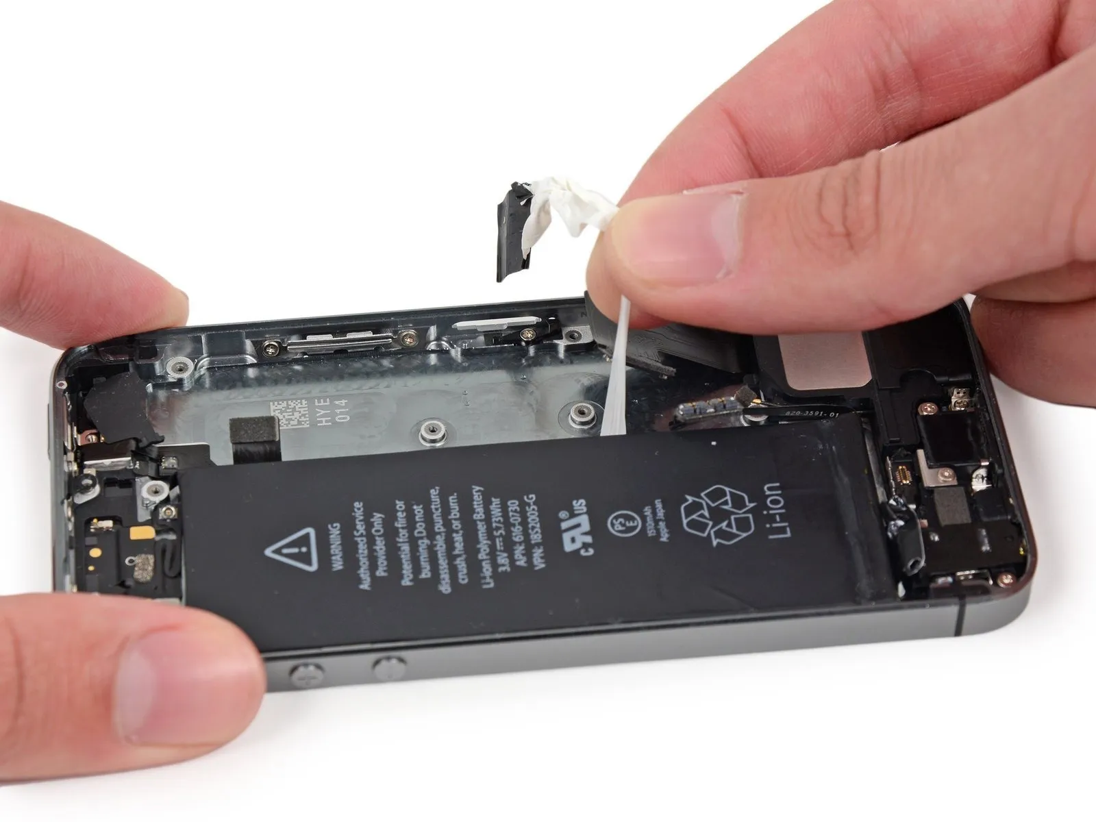
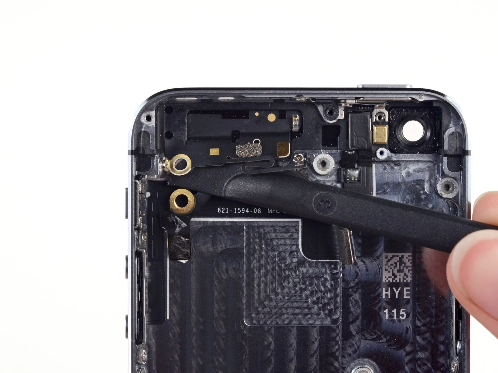
Carefully detach the Bluetooth and Wi-Fi antenna, ensuring no damage occurs.
To prevent conductivity issues caused by oils from your skin, avoid direct contact with metal-to-metal interfaces; utilize tweezers or gloves instead. Should contact occur, thoroughly clean those areas with a degreaser, such as Windex or isopropyl alcohol, prior to reassembling the device.
To prevent conductivity issues caused by oils from your skin, avoid direct contact with metal-to-metal interfaces; utilize tweezers or gloves instead. Should contact occur, thoroughly clean those areas with a degreaser, such as Windex or isopropyl alcohol, prior to reassembling the device.