iPhone 5s Rear Case Replacement
This guide details the process of substituting a new rear case for an iPhone 5s exhibiting scratches or other damage.
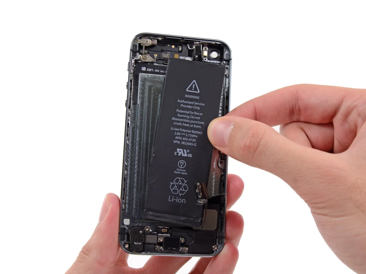
Before proceeding, disconnect the battery, noting that the battery's adhesive securing strips are single-use and will need to be replaced; ensure you have replacement strips available, or use a segment of double-sided tape to reattach the battery to the device housing.
Step 1 | Removing the Pentalobe screws

Begin the process by ensuring the 1.5mm Allen wrench is used to loosen the four retaining screws, each measuring 8mm in length, securing the fan assembly; exercise caution to prevent damage to the surrounding components.To prevent potential fire or explosion hazards during repair, ensure the iPhone's lithium-ion battery is depleted to less than 25% capacity prior to beginning work; a fully charged battery poses a significant risk of combustion if damaged.
To prevent electrical shock or damage, ensure the iPhone is completely de-energized prior to starting the repair process.
Using a Pentalobe screwdriver, detach the two screws, each measuring 3.9 mm, located on both sides of the Lightning connector.
To prevent electrical shock or damage, ensure the iPhone is completely de-energized prior to starting the repair process.
Using a Pentalobe screwdriver, detach the two screws, each measuring 3.9 mm, located on both sides of the Lightning connector.
Step 2 | Taping the display glass


Using a 5/32-inch hex key, carefully loosen the four screws securing the fan assembly to the motor housing; exercise caution to prevent damage to the plastic fan blades and ensure the assembly remains stable during removal.To mitigate the risk of additional shattering and potential injury while repairing a cracked display glass, secure it with tape.
Apply strips of transparent packing tape across the iPhone screen, ensuring complete coverage by slightly overlapping each strip.
To prevent scattered glass fragments and maintain stability during the display separation process, this technique is essential.
To safeguard your eyes from potential glass fragments released during the repair process, always use safety glasses.
Step 3 | Display separation prevention


Using a 5/32-inch hex key, carefully tighten the three retaining screws on the motor assembly to a torque of 3.5 inch-pounds, ensuring not to overtighten and potentially strip the threads.Carefully lift the display assembly—consisting of a glass screen, a plastic bezel, and integrated metal clips—from within the phone's chassis during the subsequent procedures.
Ensure complete removal of the display assembly, irrespective of the specific tool employed.
When the glass and plastic layers detach, referencing the initial image for visual guidance, use a plastic opening tool to carefully insert it into the gap between the plastic frame and the phone's metal chassis, releasing the retaining clips.
To ensure proper closure during reassembly when the display bezel is detached, apply a narrow adhesive strip along the interface between the plastic bezel and the glass.
Step 4 | Anti-Clamp instructions


Using a 5/32-inch hex key, carefully tighten the three retaining screws on the motor assembly to a torque of 4 in-lbs, ensuring not to overtighten and potentially strip the threads.To simplify the subsequent opening process, the following instructions utilize the Anti-Clamp tool, a custom design; if you do not have this tool, proceed two steps further to find an alternative procedure.
Refer to the included guide for detailed procedures regarding Anti-Clamp operation.
To release the Anti-Clamp's arms, move the blue handle in a rearward direction.
Position the arms so they extend across the iPhone's left or right side.
Secure two suction cups, one to the front surface and one to the rear surface of the iPhone, placing them close to the lower edge, directly above the home button.
Apply vacuum by pressing the cups firmly against the surface you intend to work on.
To enhance the Anti-Clamp's grip if the iPhone's exterior feels excessively smooth, apply the provided adhesive pad to generate a more textured contact area.
Step 5


Using a 5/32-inch hex key, carefully tighten the four retaining screws on the motor assembly to a torque of 4.5 Nm, ensuring you observe the warning regarding potential damage to the threads if overtightening occurs.To secure the arms, advance the blue handle in the direction indicated.
Rotate the handle fully, completing a 360-degree turn, observing for the initial signs of cup expansion.
Maintain parallel positioning of the suction cups; should misalignment occur, gently release the suction cups' hold and reposition the arms.
Once sufficient space is created by the Anti-Clamp, slide a prying tool beneath the display panel.
To ensure adequate separation, adjust the handle's position by 90 degrees.
Apply adjustments in increments not exceeding 90 degrees, pausing several seconds after each adjustment to allow the Anti-Clamp mechanism and settling time to function.
Step 6 | Manual Opening Procedure

Lacking an Anti-Clamp tool, secure the front panel with a single suction cup for lifting.
Position a suction cup directly on the display surface, situated slightly higher than the home button's location.
Ensure the screen's entire surface is covered by the cup to guarantee a secure connection.
Position a suction cup directly on the display surface, situated slightly higher than the home button's location.
Ensure the screen's entire surface is covered by the cup to guarantee a secure connection.
Step 7 | Start lifting the front panel assembly

To access the internal components, carefully detach the front panel's retaining clips, then gently separate the phone's housing just enough to allow disconnection of the multiple ribbon cables; proceed with caution to prevent any damage.
Securely affix the suction cup to the front panel assembly, positioning it close to the home button.
Using one hand to secure the iPhone, lift the suction cup vertically to gently create a small gap between the front panel and the rear case, beginning at the home button area.
Using a plastic opening tool, carefully separate the rear case from the front panel assembly by gently levering the edges, simultaneously lifting with a suction cup.
Exercise caution and use steady, even pressure when installing the front panel assembly, as its fit is considerably more snug than typical device designs.
Step 8


Disconnecting the front panel assembly from the rear case should be avoided; multiple fragile ribbon cables secure the two components together.
To detach the suction cup, depress the small plastic projection that maintains the airtight seal.
Carefully detach the screen from the display using the suction cup.
To detach the suction cup, depress the small plastic projection that maintains the airtight seal.
Carefully detach the screen from the display using the suction cup.
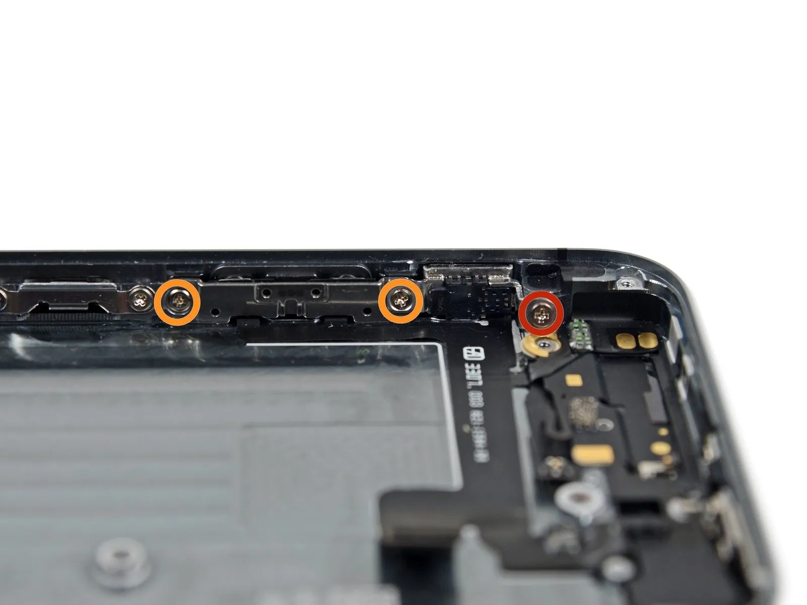
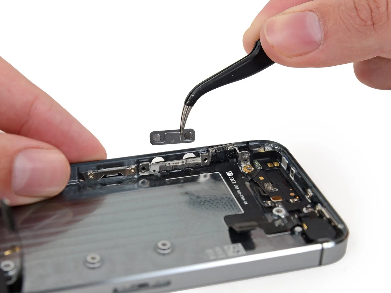
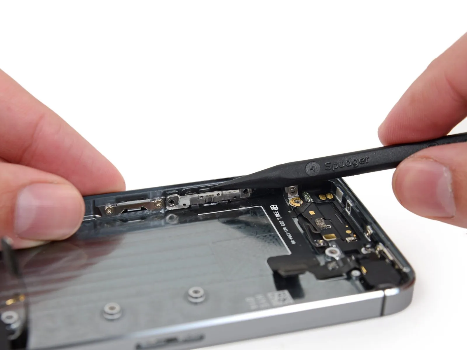
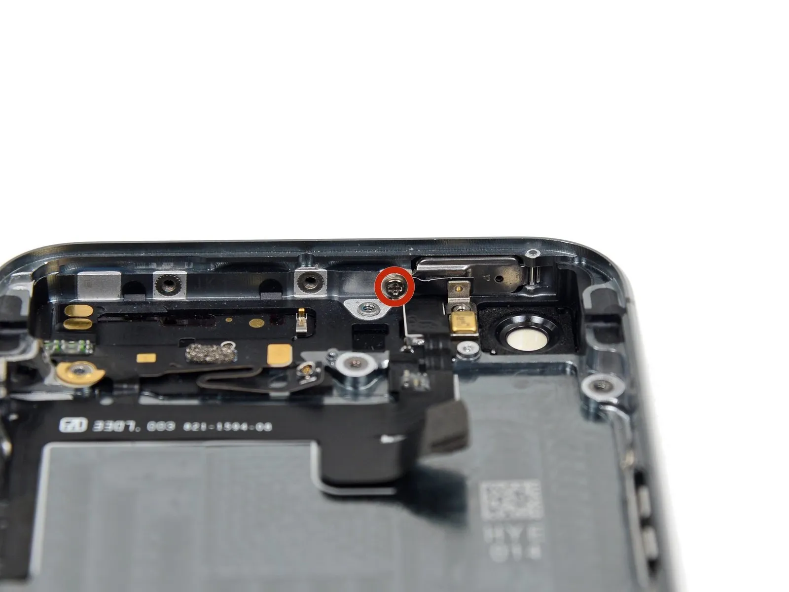
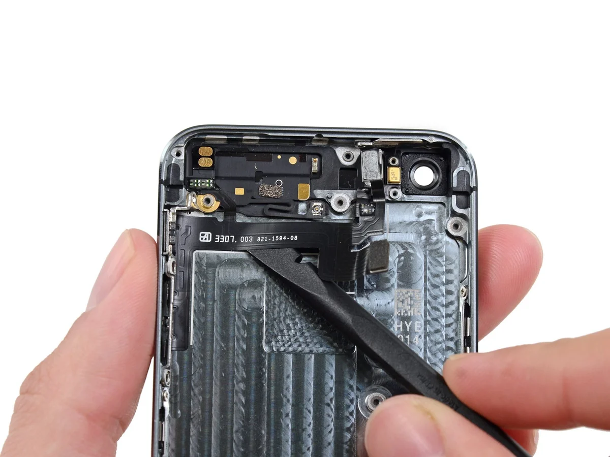
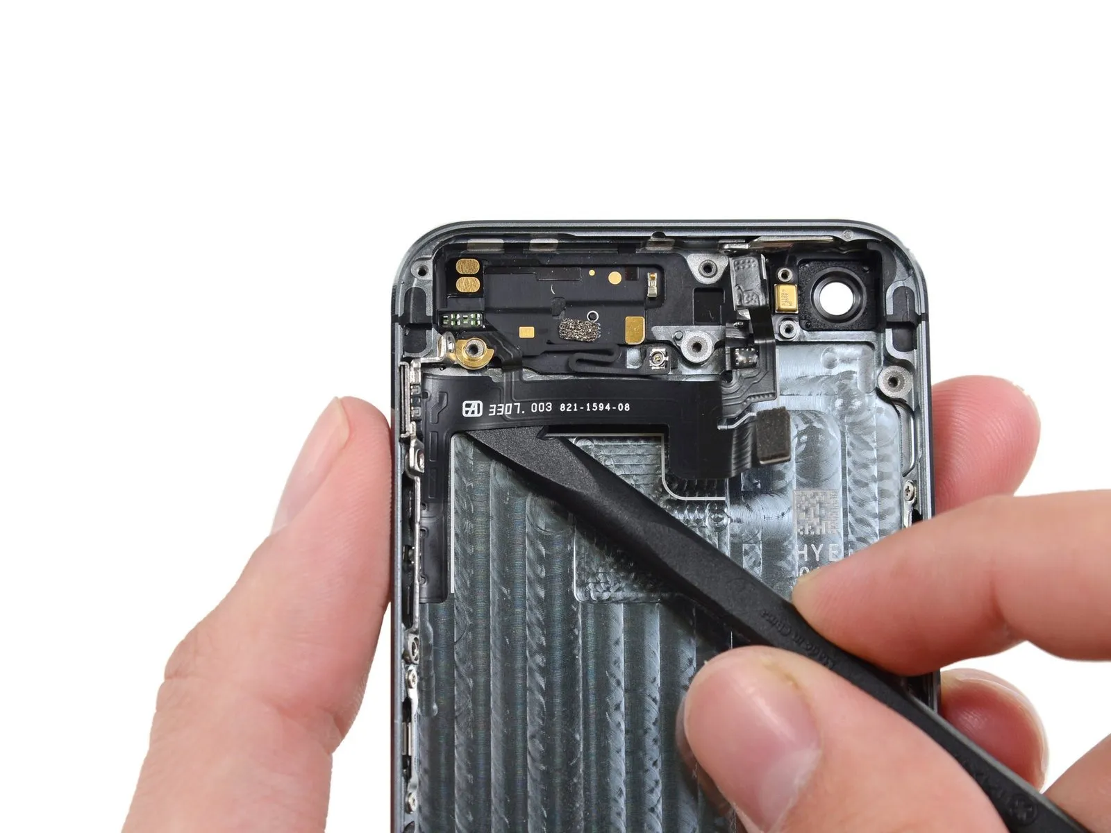
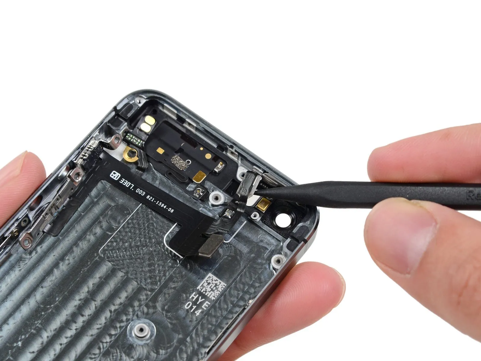
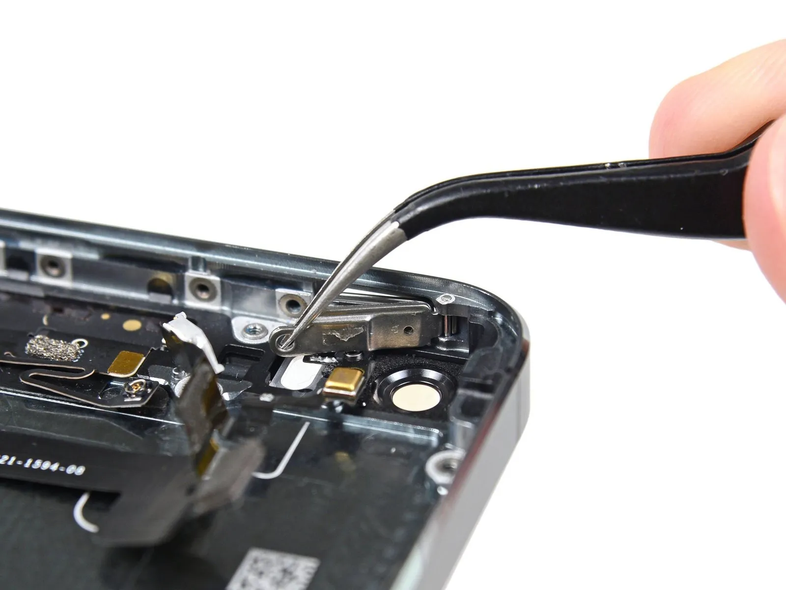
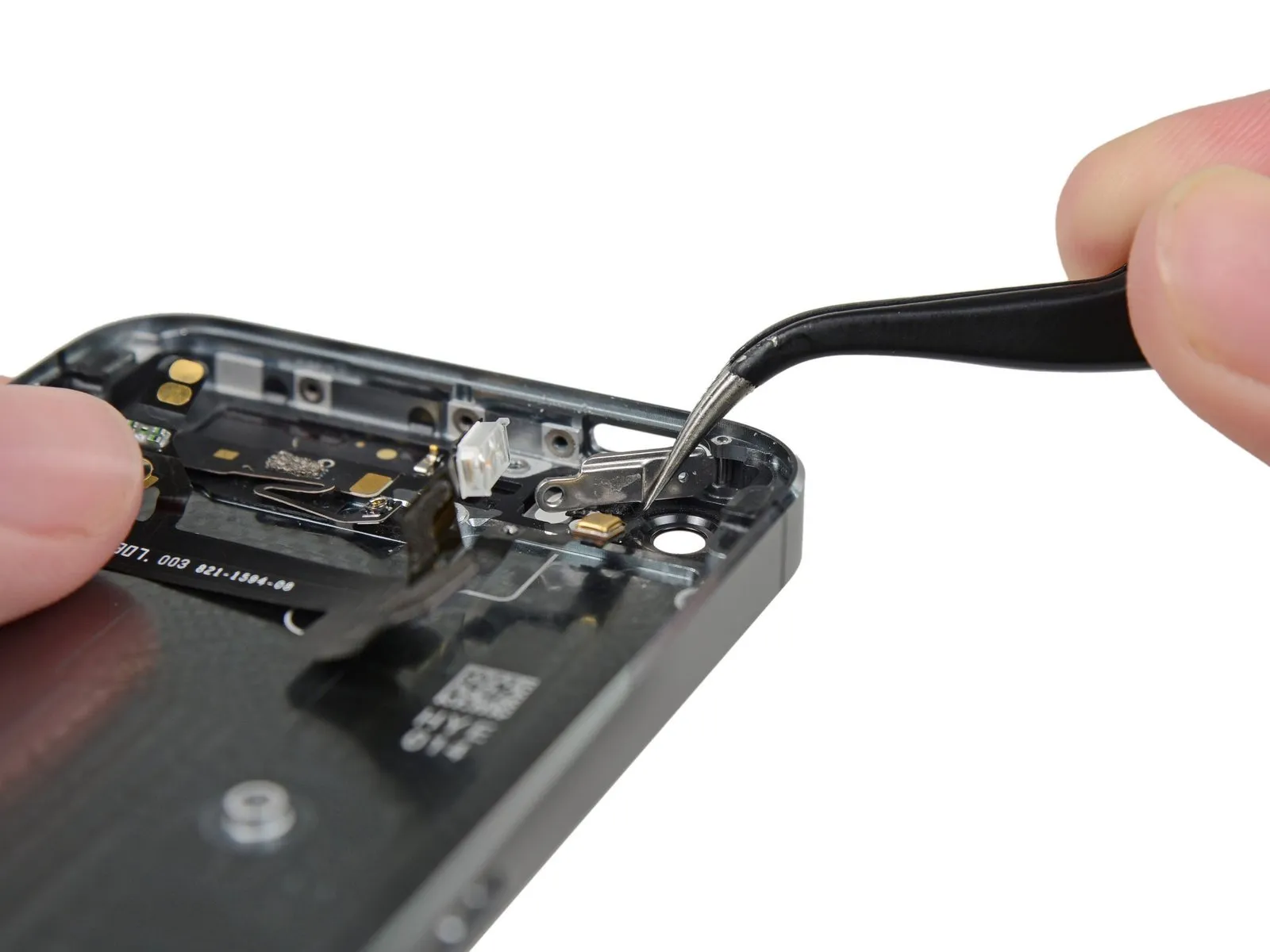
Step 9 | Removing the Touch ID cable bracket


Carefully separate the phone's casing to expose the metallic support securing the home button cable.
To prevent damage to either the home button cable or its connector, avoid excessive separation of the phone's housing; maintain slack in the cable during disassembly, as overextension can cause harm.
The Touch ID feature requires the use of the phone's factory-installed home button assembly; replacement with a non-original part will result in a standard home button function only, disabling Touch ID capabilities.
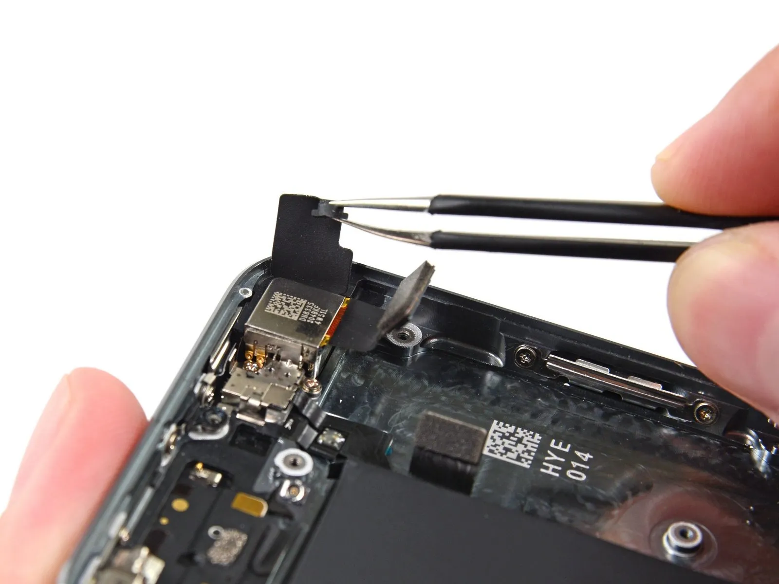
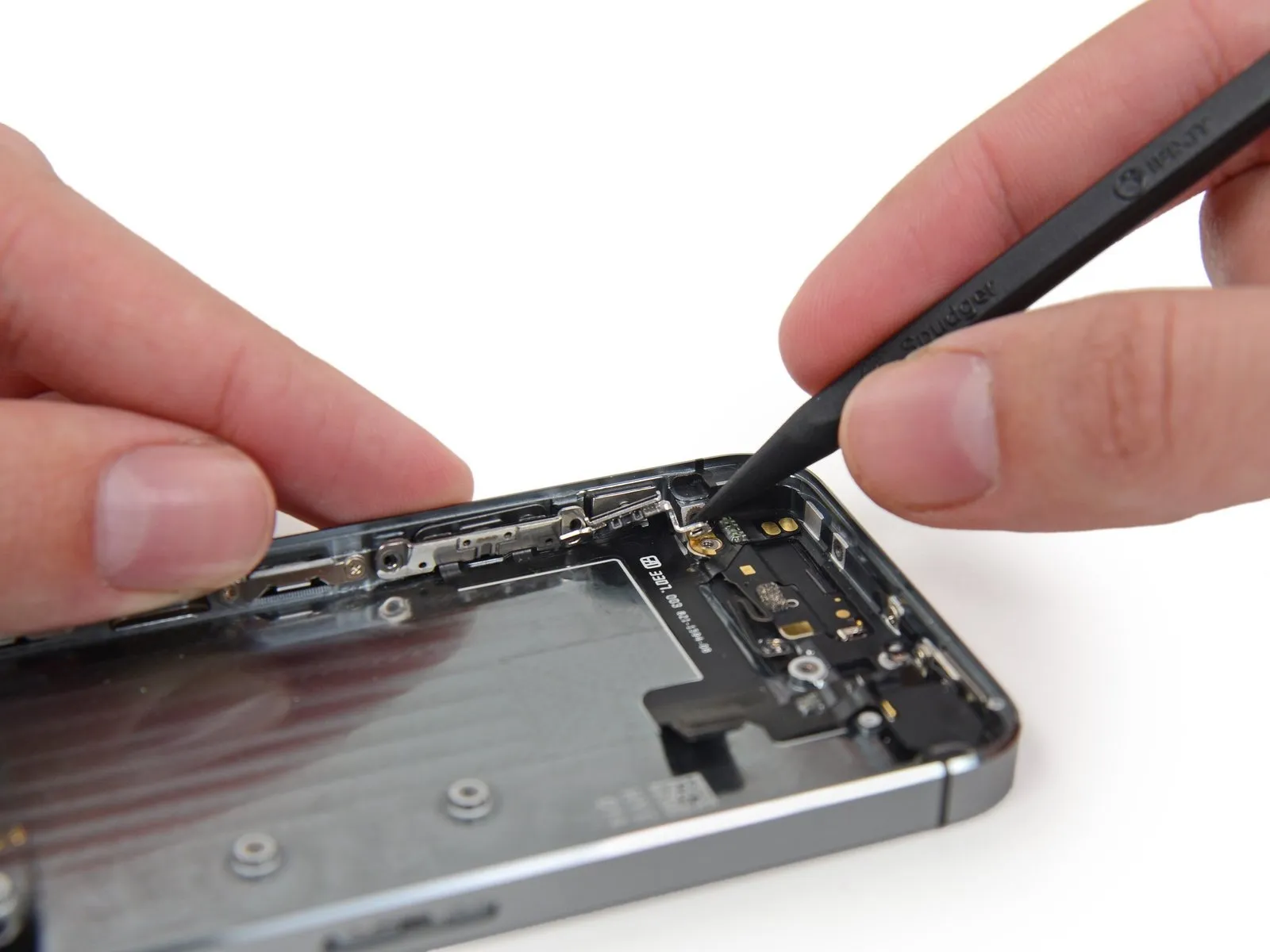
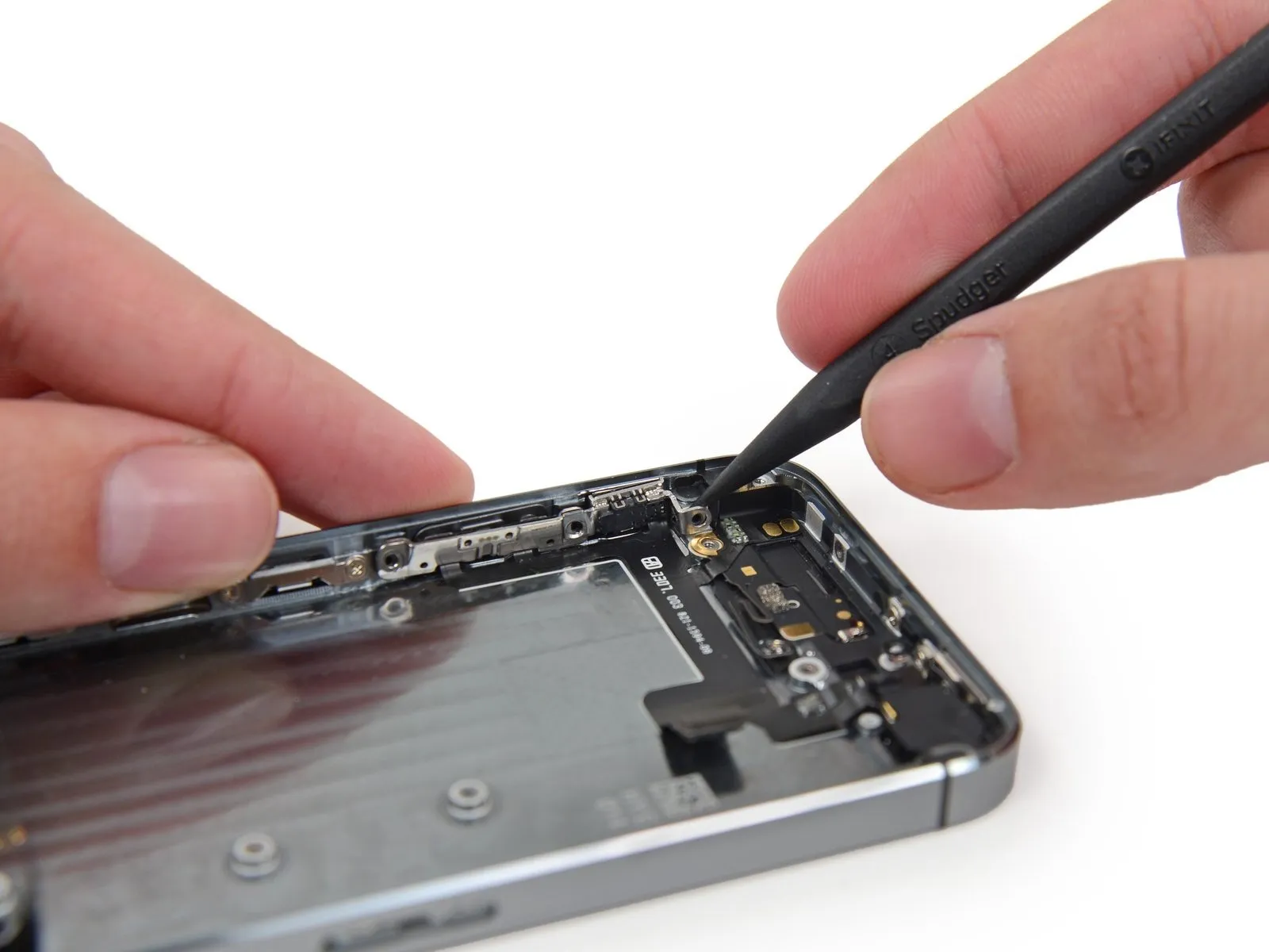
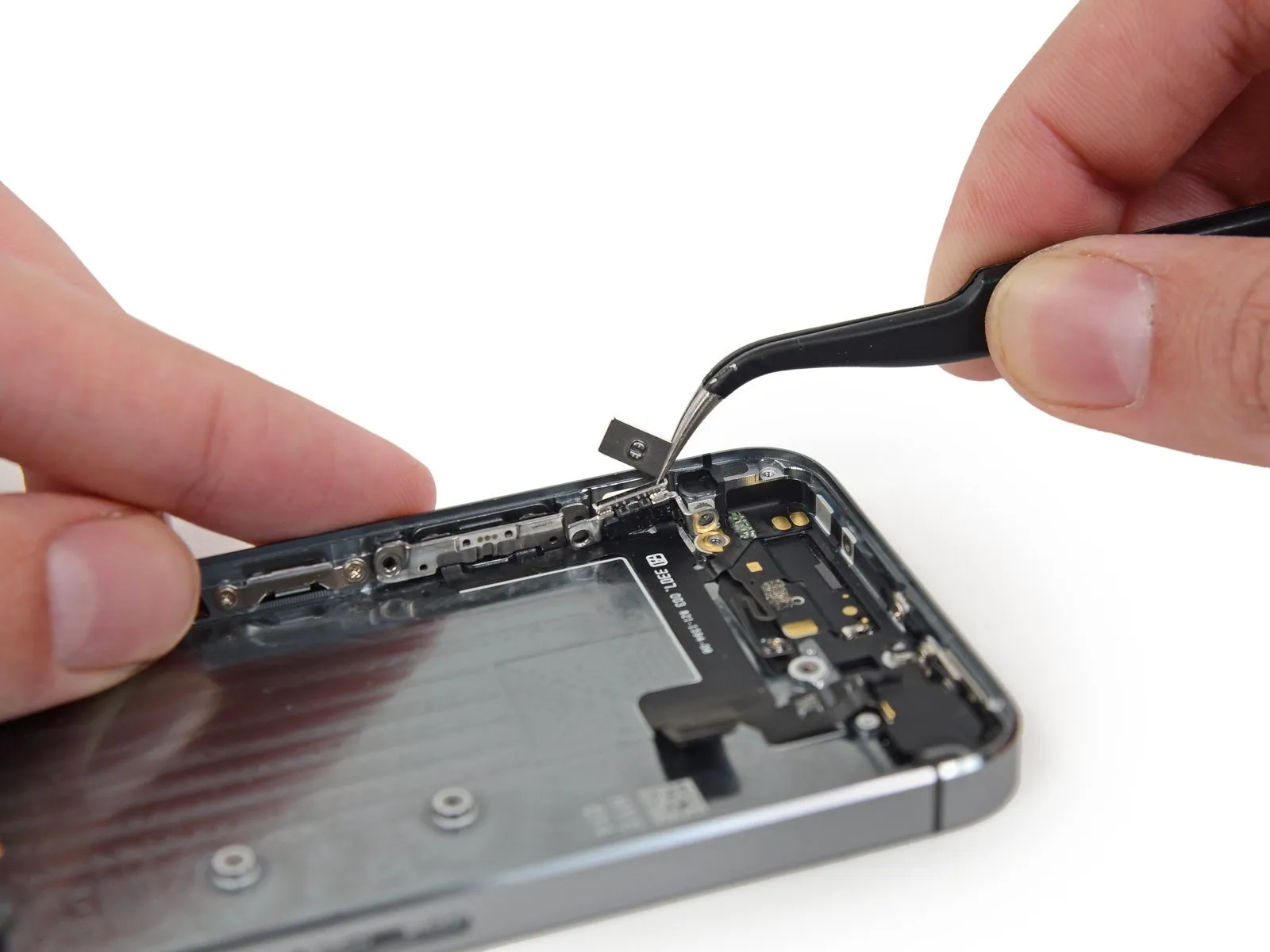
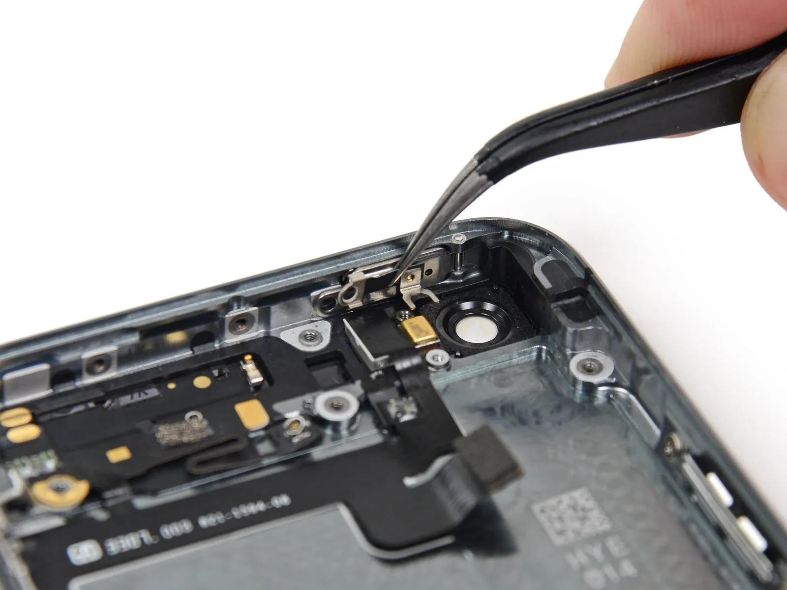
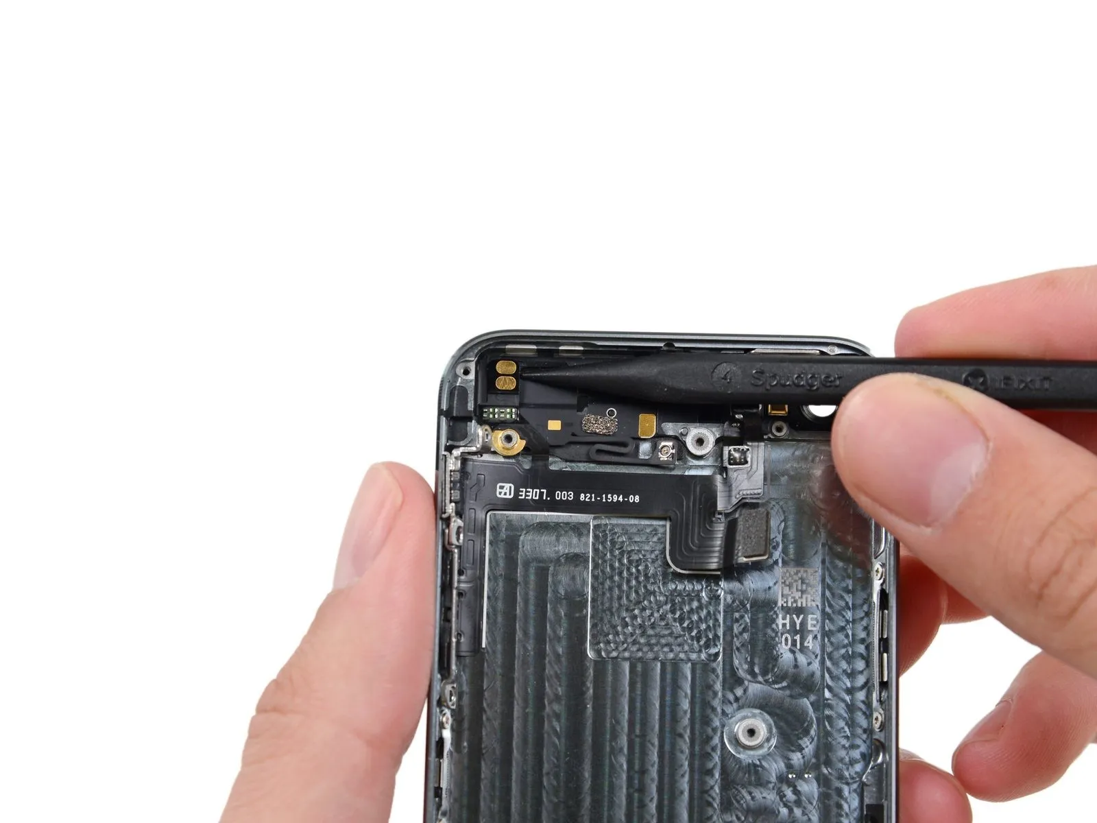
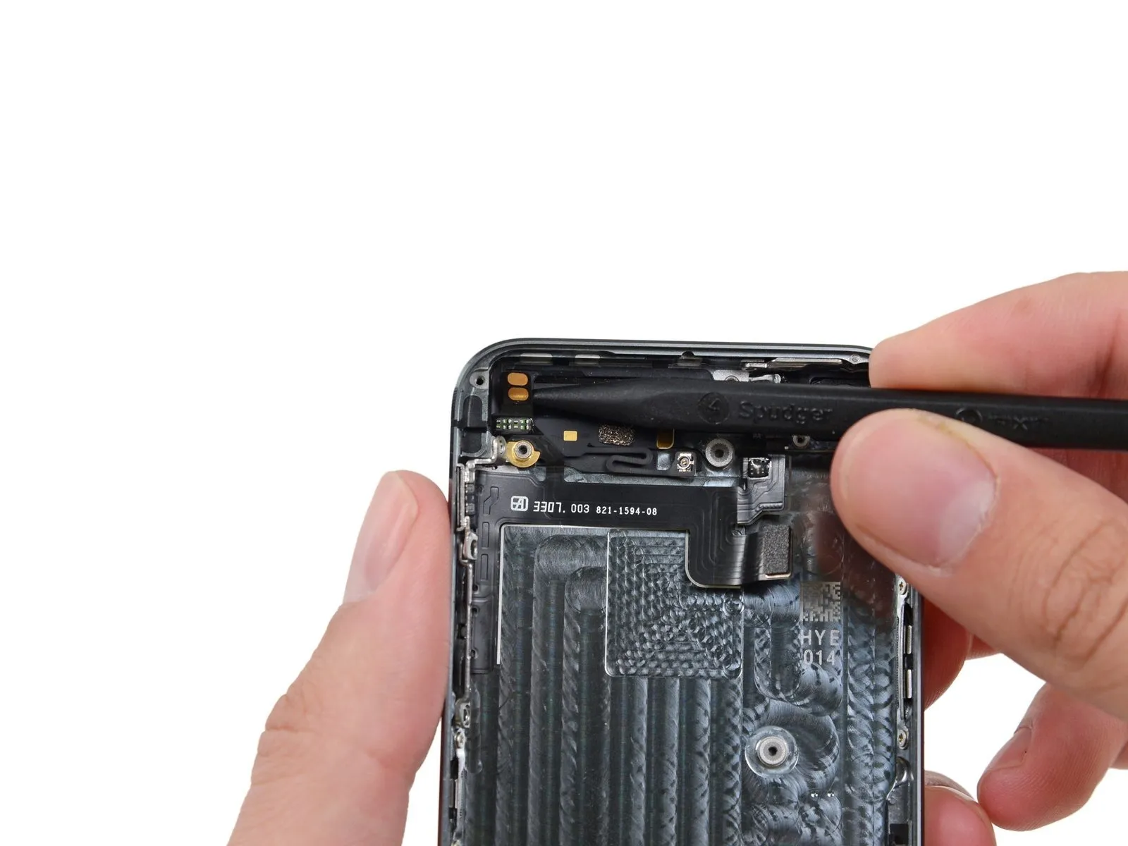
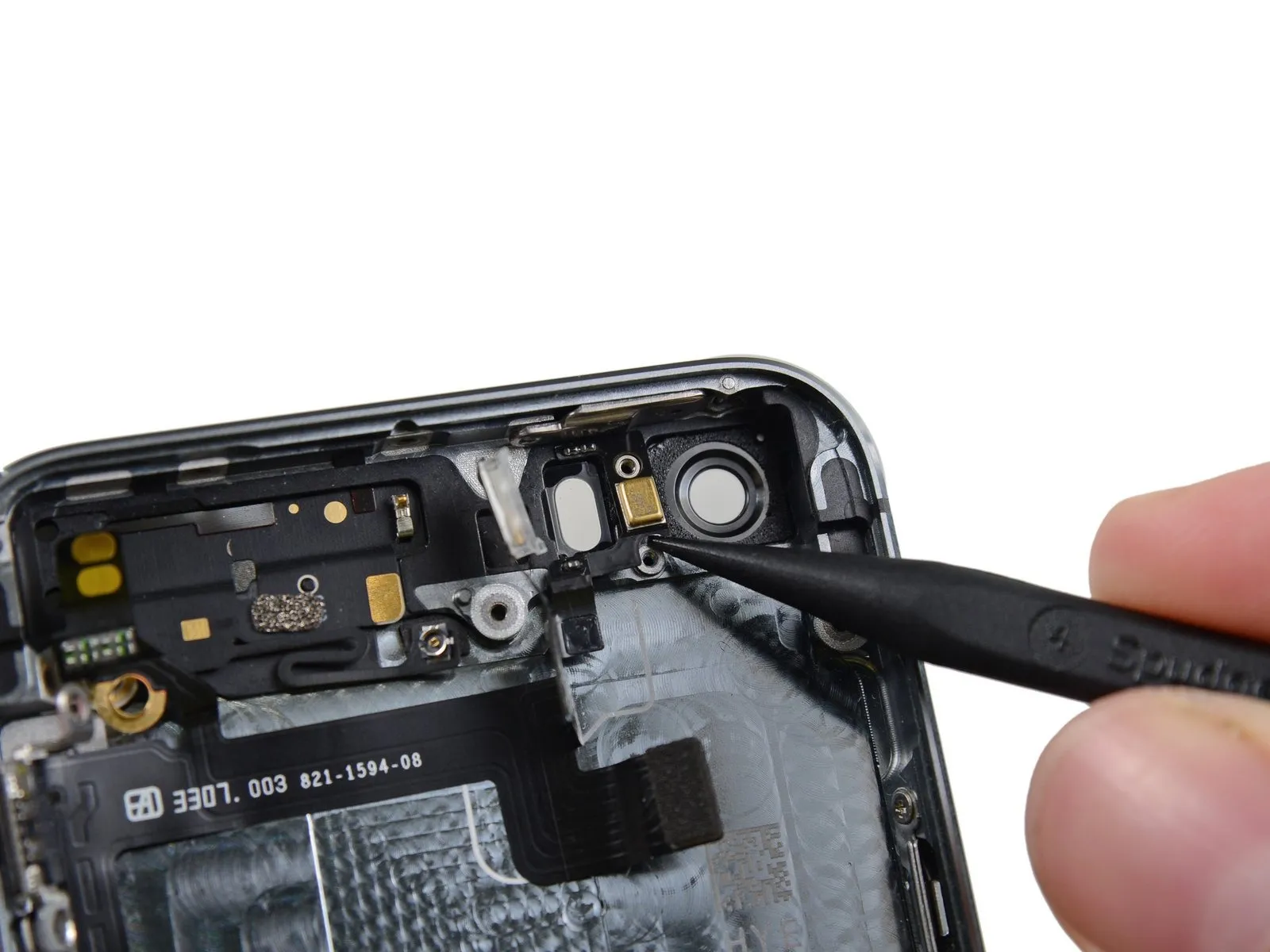
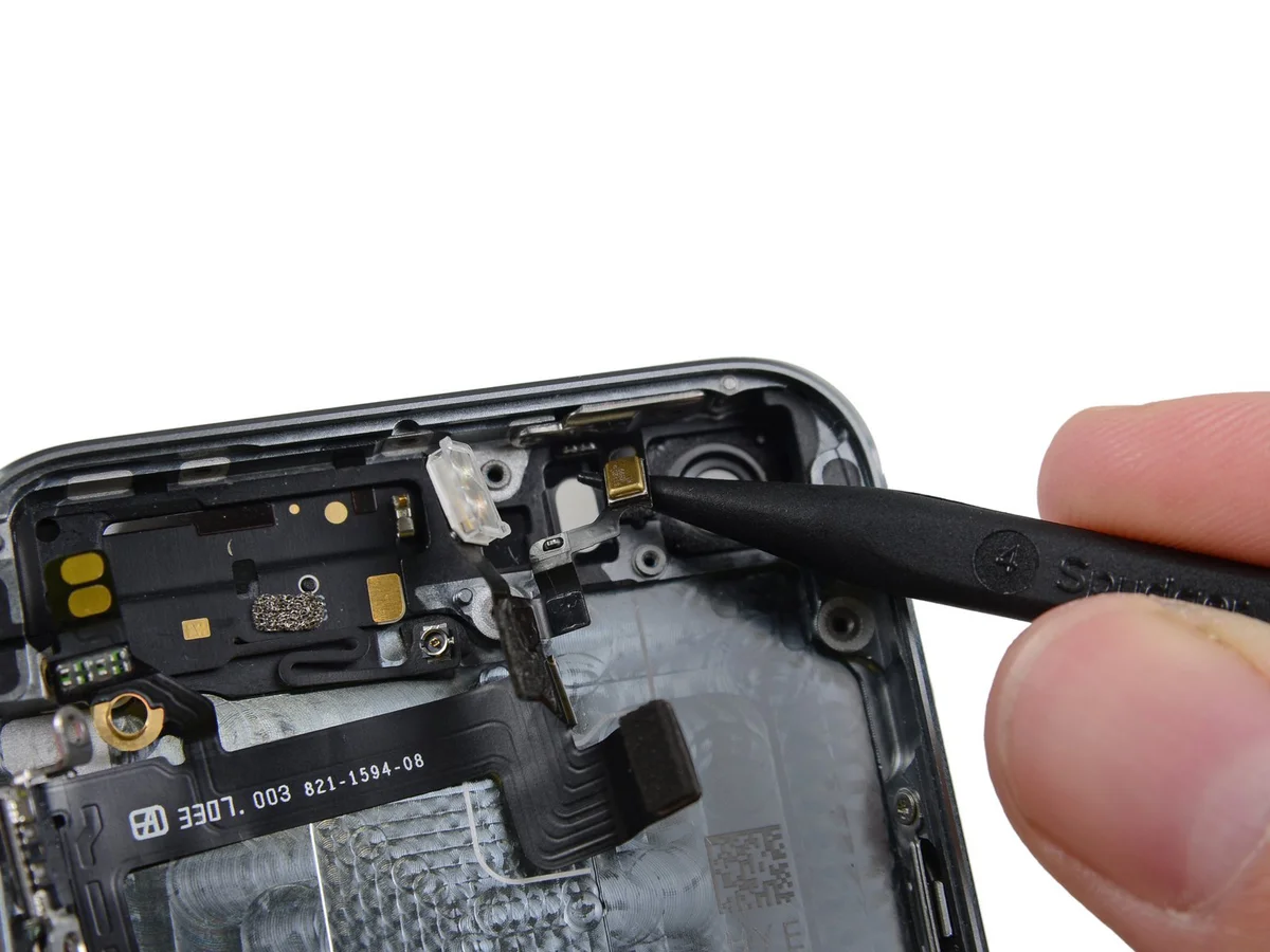
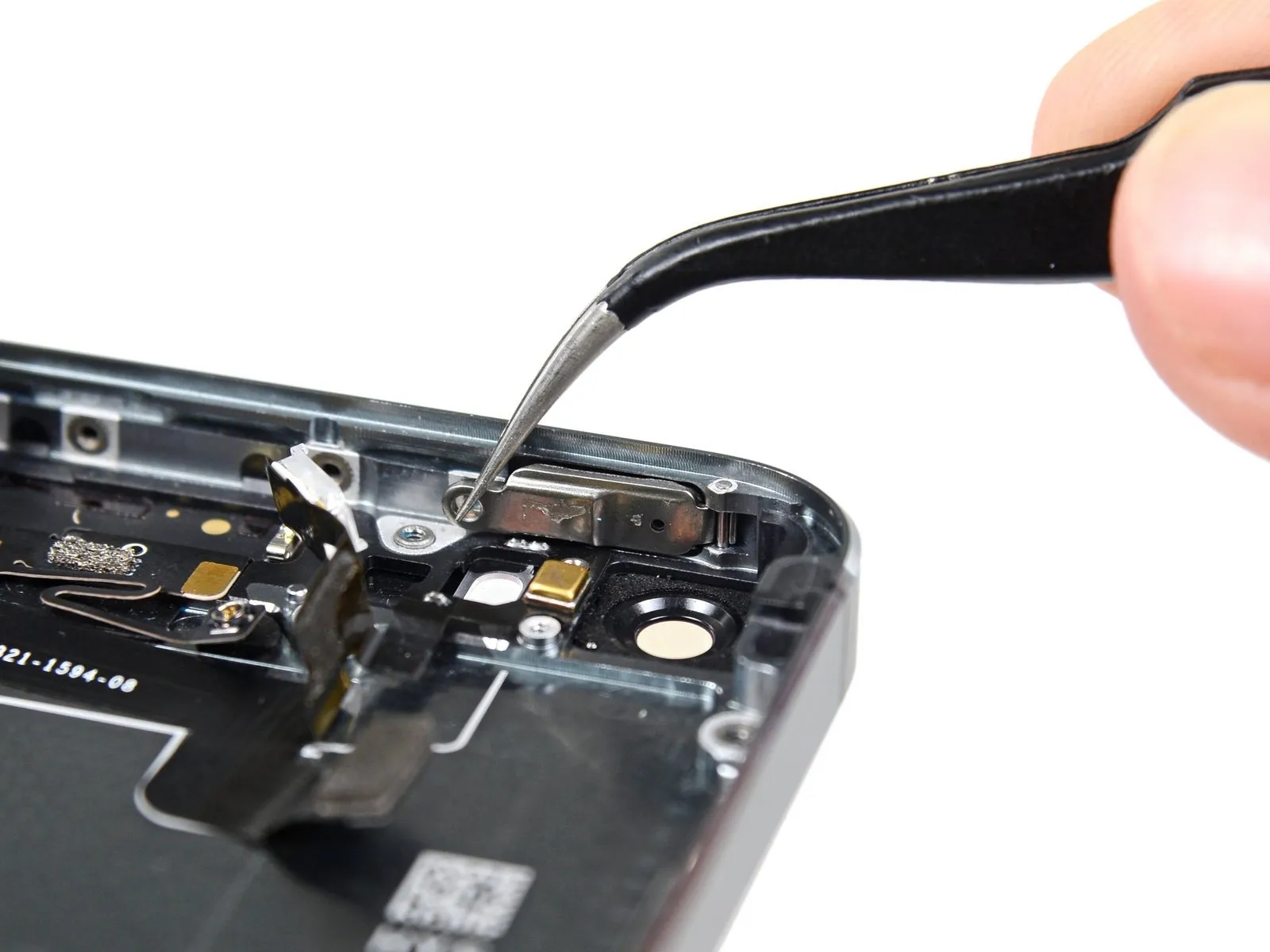
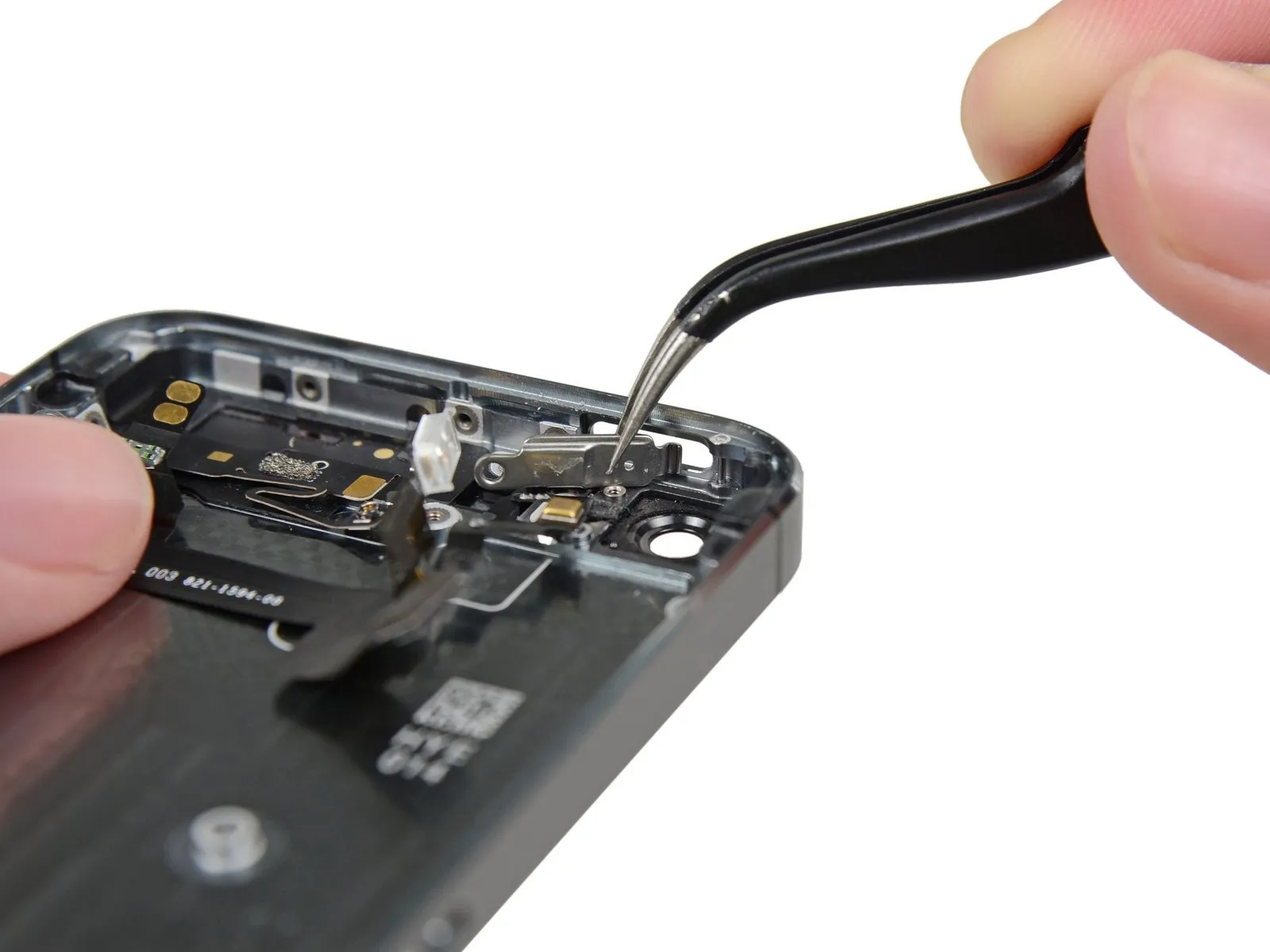
Carefully leverage the bracket loose using a spudger tip, then grasp and detach it with tweezers.
For reassembly procedures, proceed with the subsequent two instructions; otherwise, advance directly to Step 12.
To prevent damage to either the home button cable or its connector, avoid excessive separation of the phone's housing; maintain slack in the cable during disassembly, as overextension can cause harm.
The Touch ID feature requires the use of the phone's factory-installed home button assembly; replacement with a non-original part will result in a standard home button function only, disabling Touch ID capabilities.
Carefully leverage the bracket loose using a spudger tip, then grasp and detach it with tweezers.
For reassembly procedures, proceed with the subsequent two instructions; otherwise, advance directly to Step 12.
Step 10


To complete reassembly, secure the Touch ID cable bracket by guiding its upper edge between the battery and the Touch ID cable connector, positioning it ahead of the metal tab; then, fasten the bracket's lower edge over the connector.
Align the bracket's upper edge with the Touch ID cable connector and move it horizontally, ensuring it fully engages from the left side.
Position the bracket so it rests on the connector, ensuring the "leg" side creates a small upward tilt and the opposing edge aligns between the connector and the battery's adjacent metal tab. Using a spudger, press gently downward on the bracket to secure both the rear and front clasps.
Step 11


Carefully position the Touch ID cable bracket's front section over the cable connector, then secure it by pressing downward with the flat edge of a spudger.
To ensure the bracket sits level against the surface, reposition it by sliding it back over the cable connector if it doesn't seat properly.
To ensure the bracket sits level against the surface, reposition it by sliding it back over the cable connector if it doesn't seat properly.
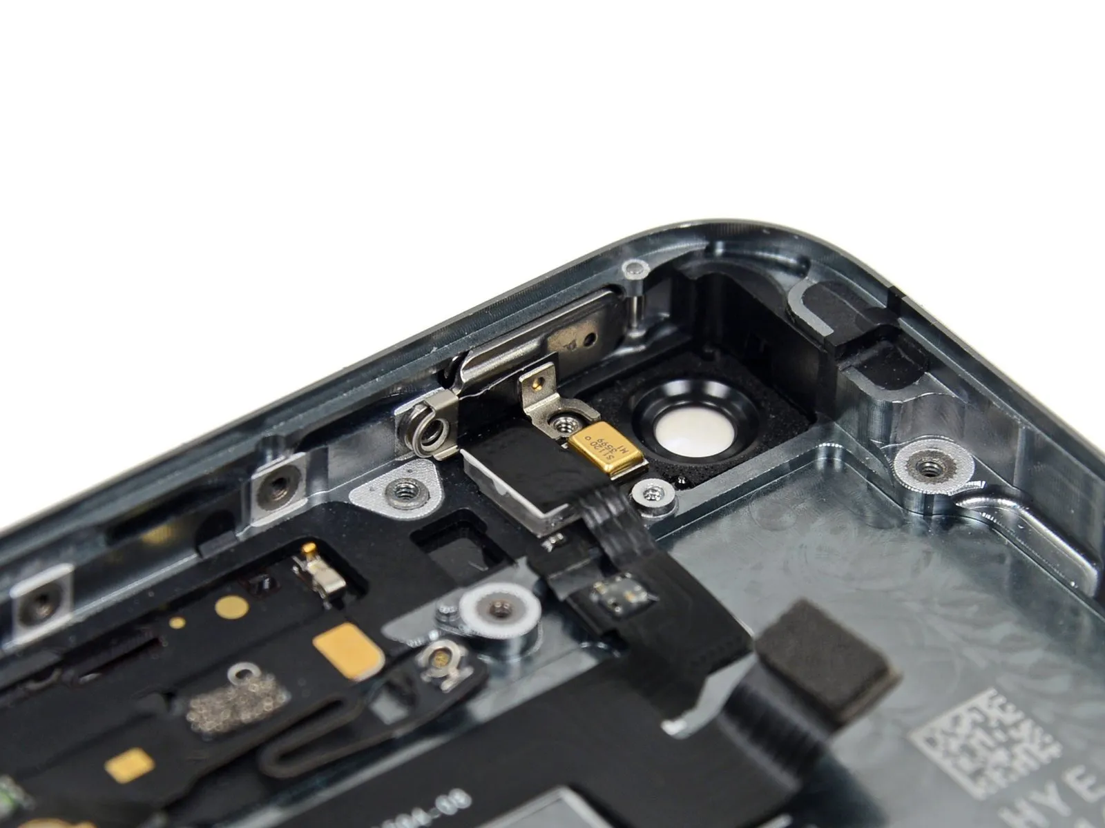
Step 12 | Disconnecting the home button cable connector


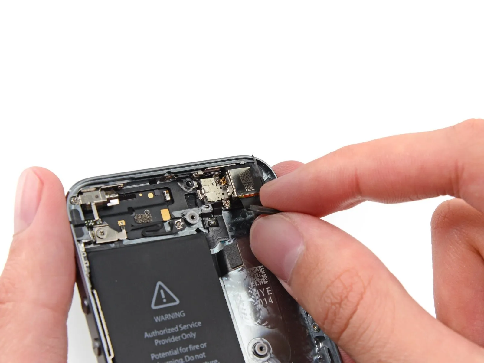
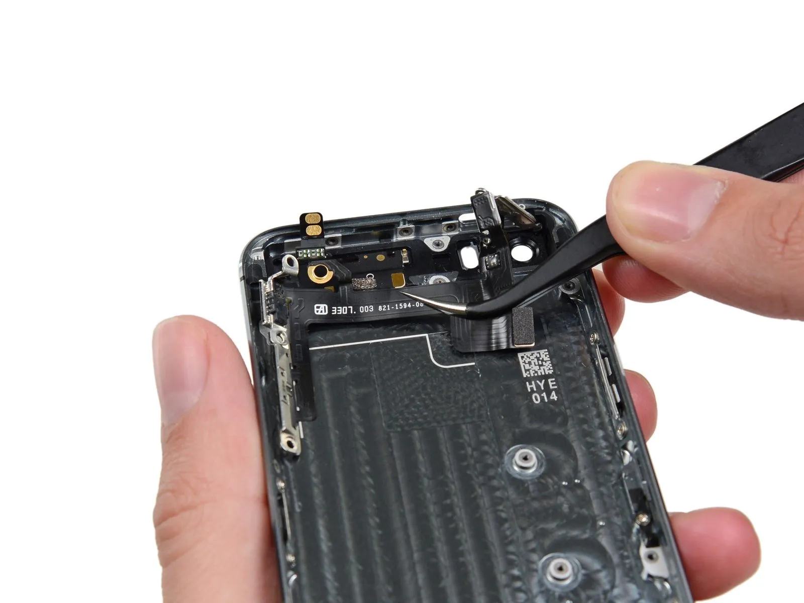
Carefully lift the home button cable connector from its socket using the pointed end of a spudger.
Carefully detach the cable connector from its receptacle; avoid lifting the receptacle itself, as it's affixed to a cable secured with adhesive that can be dislodged if excessive force is applied.
Carefully detach the cable connector from its receptacle; avoid lifting the receptacle itself, as it's affixed to a cable secured with adhesive that can be dislodged if excessive force is applied.
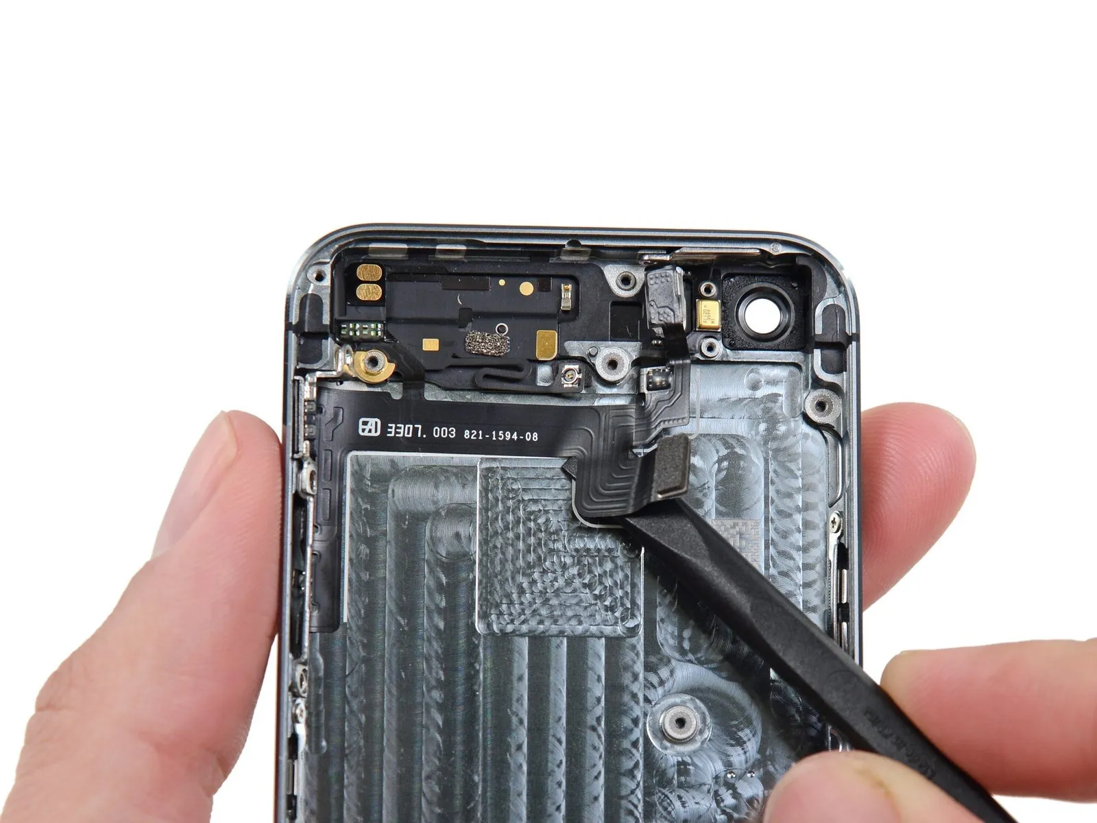
Step 13 | Opening up the phone


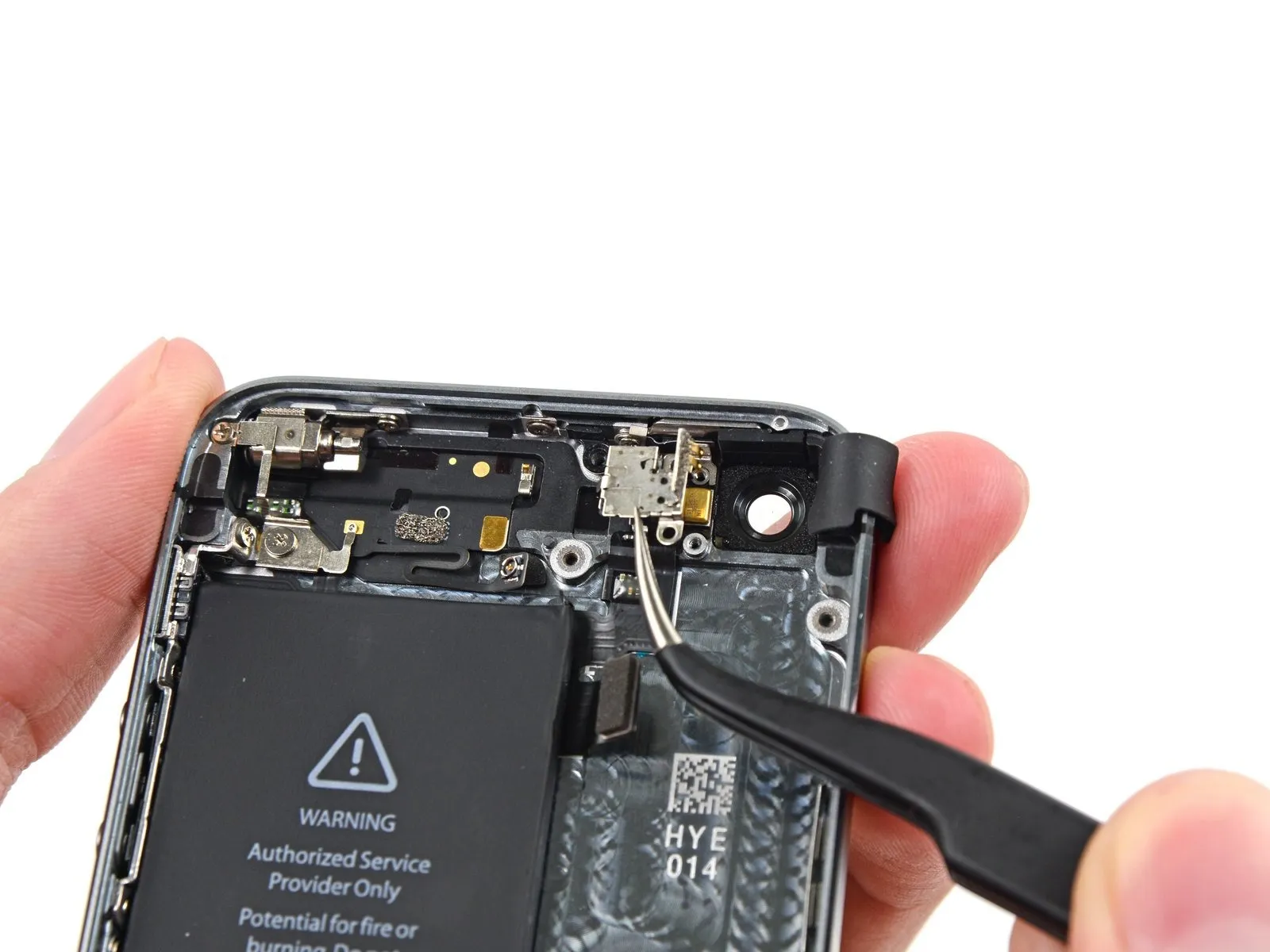
Carefully detach the connector, then pivot the assembly containing the home button outward, utilizing the phone's upper edge as a fulcrum.
Carefully position the display at a 90-degree angle, then secure it in an upright position using a support to allow for hands-free access during the repair process.
To avoid stressing the display's wiring during the repair process, secure it with a rubber band.
As a temporary measure, an unused, sealed can of soda can substitute for the display during the repair process.
Step 14

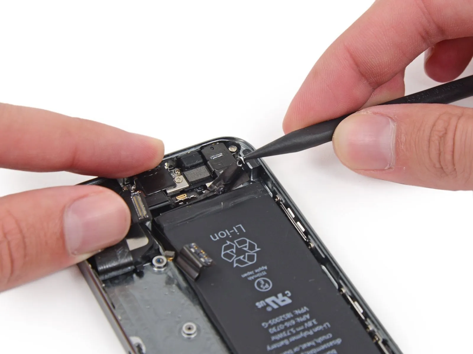
Using a Phillips #000 screwdriver, detach the metal bracket that holds the battery connector by unscrewing the two 1.6 mm screws fastening it to the logic board.
Step 15

Detach the bracket securing the battery connector using a tri-point screwdriver, ensuring no damage occurs to surrounding components.
Step 16


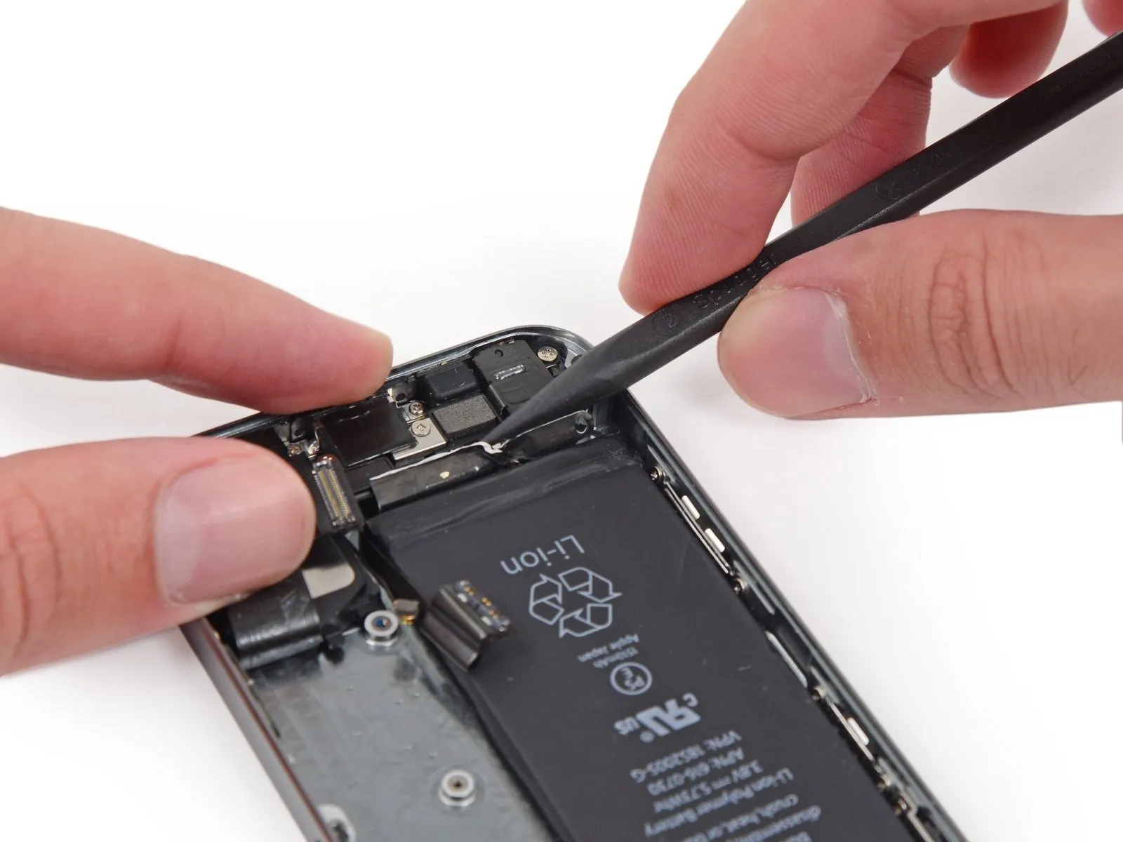
Carefully lift the battery connector away from its corresponding socket on the logic board, employing the flat edge of a spudger to avoid damage.
Exercise extreme caution when releasing the battery connector, ensuring force is applied solely to the connector and not the logic board socket; applying pressure to the socket or the board risks socket destruction or damage to adjacent components.
Exercise extreme caution when releasing the battery connector, ensuring force is applied solely to the connector and not the logic board socket; applying pressure to the socket or the board risks socket destruction or damage to adjacent components.
Step 17

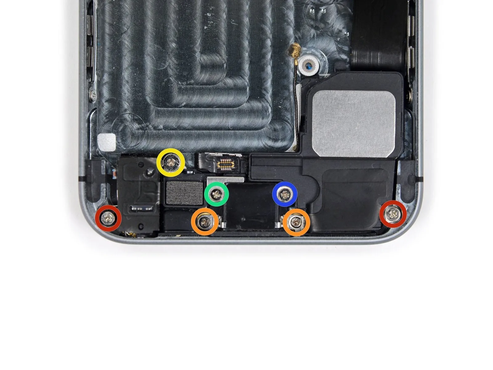
Detach the cable bracket from the logic board by unscrewing the screws listed below.
Carefully manage all screws during this procedure to ensure correct reassembly; incorrect placement, such as using a 1.3 mm or 1.7 mm screw in the bottom right hole, will severely damage the logic board and prevent the device from powering on.
Avoid applying excessive force when tightening screws; overtightening can damage components. If a screw encounters resistance during installation, verify it is the correct size.
- A Phillips head screwdriver, size #000, is needed to remove a 1.7-millimeter screw.
- A Phillips head screwdriver, size #000, is needed to remove a 1.2-millimeter screw.
- A Phillips head screw, size #000 and measuring 1.3 millimeters.
- An additional screw, measuring 1.7 mm in width and utilizing a Phillips #000 head, is required.
Carefully manage all screws during this procedure to ensure correct reassembly; incorrect placement, such as using a 1.3 mm or 1.7 mm screw in the bottom right hole, will severely damage the logic board and prevent the device from powering on.
Avoid applying excessive force when tightening screws; overtightening can damage components. If a screw encounters resistance during installation, verify it is the correct size.
Step 18

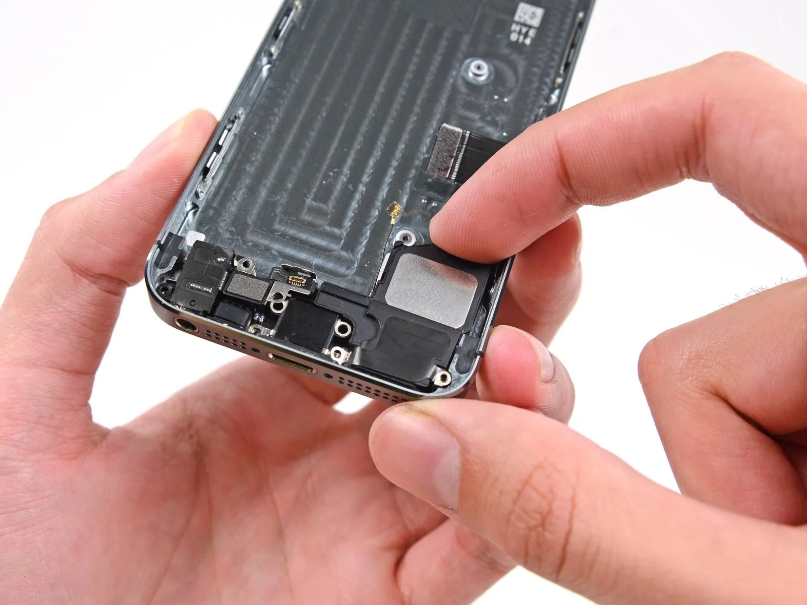
Detach the cable bracket securing the front panel assembly cable to the logic board.
Step 19


Carefully detach the front camera and its associated sensor connector from the device using a spudger or similar tool.
Step 20


Prior to either detaching or reattaching the cable in this procedure, ensure the battery is disconnected.
Carefully detach the LCD cable connector.
Should the LCD cable detach from its connector during reassembly, a blank screen or white lines may appear upon powering on the device; to resolve this, re-establish the cable's connection and restart the phone, preferably by disconnecting and reconnecting the battery.
Step 21


Carefully detach the digitizer cable's connector.
Step 22

Detach the front panel assembly from the rear case.
Step 23 | SIM Card
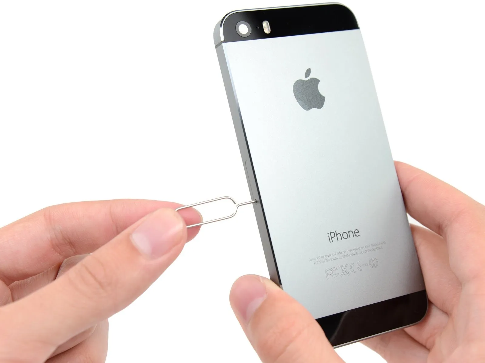
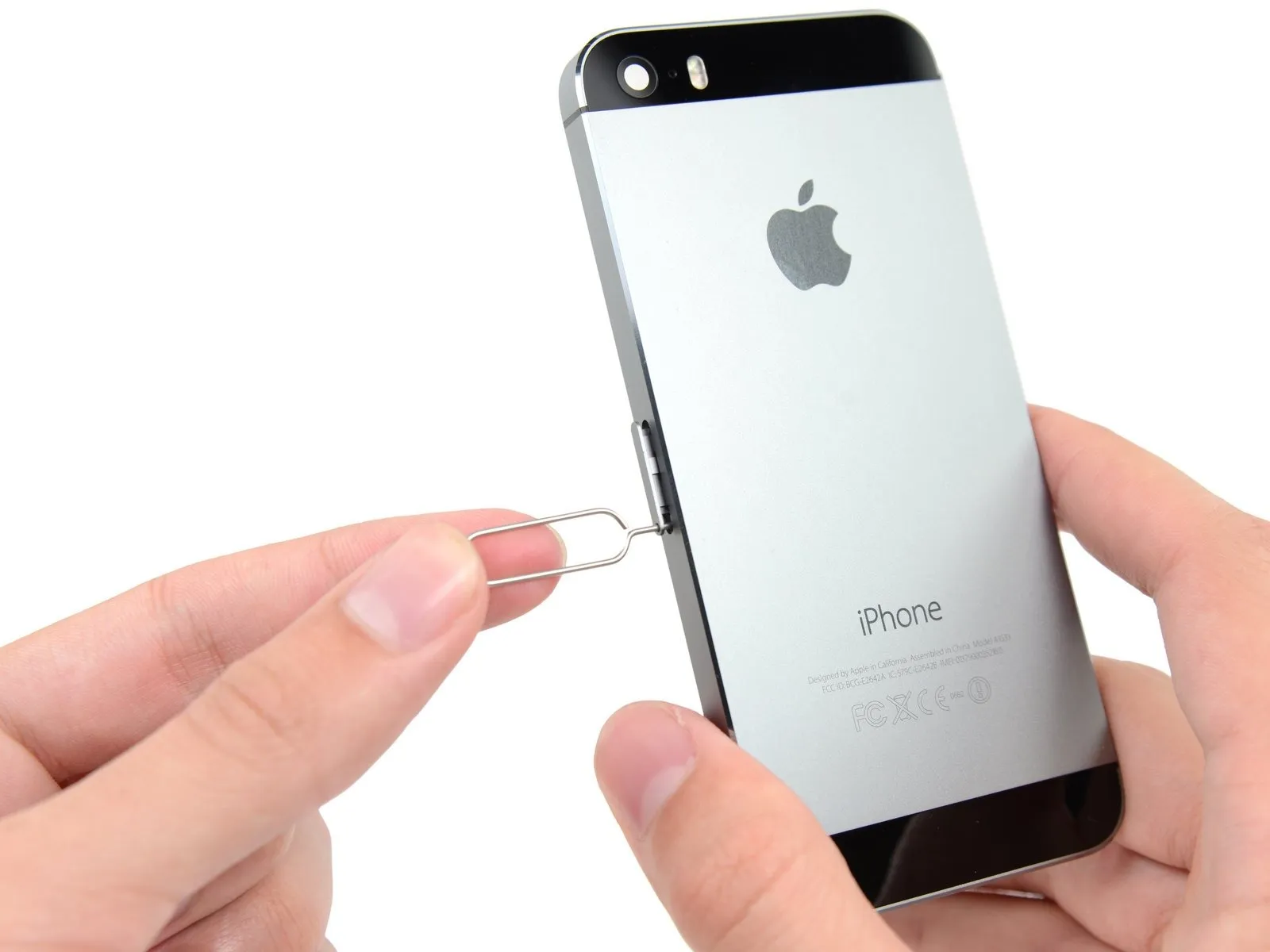
Using a SIM card eject tool or a straightened paperclip, gently push into the tiny aperture located on the SIM card tray to release it.
Apply substantial pressure until the tray releases.
Apply substantial pressure until the tray releases.
Step 24
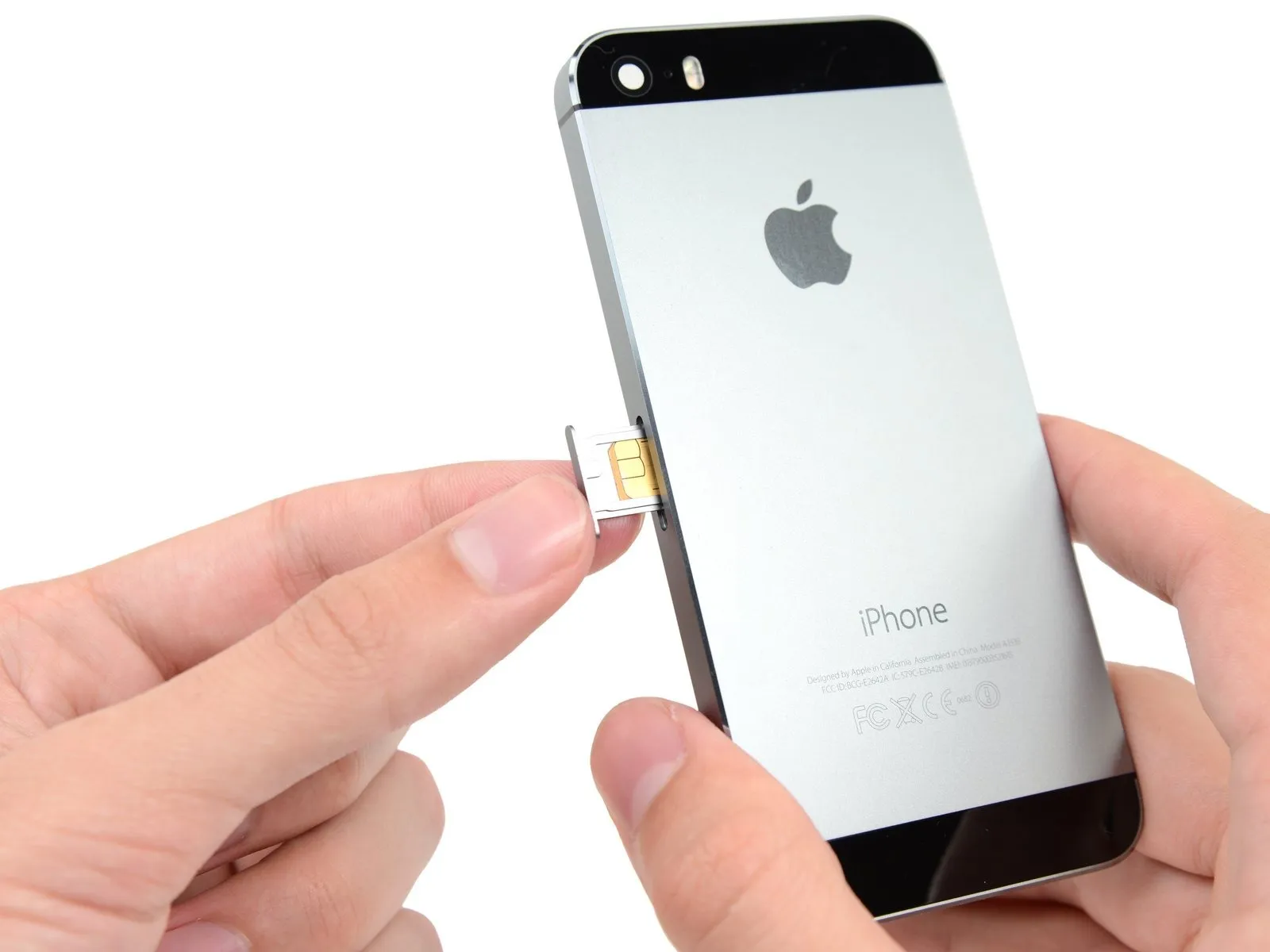
Using the SIM eject tool or a similar small, pointed object, carefully depress the SIM Card tray release until the tray pops out, then extract the SIM Card tray assembly from the iPhone.
Confirm the SIM card's alignment with the tray before sliding it back in.
Confirm the SIM card's alignment with the tray before sliding it back in.
Step 25 | Logic Board


Carefully lift the button assembly cable from its connection on the logic board using a spudger, applying gentle force.
Exercise extreme caution to avoid applying force to the logic board socket while releasing the connector; doing so risks irreparable damage to the connector itself.
Exercise extreme caution to avoid applying force to the logic board socket while releasing the connector; doing so risks irreparable damage to the connector itself.
Step 26


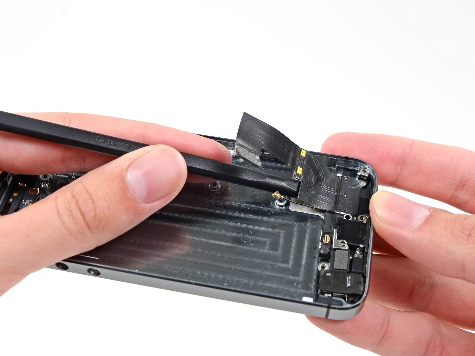
Carefully leverage a spudger to disengage the Lightning connector cable from its socket within the logic board.
To access the logic board, carefully maneuver the Lightning connector cable aside.
To access the logic board, carefully maneuver the Lightning connector cable aside.
Step 27


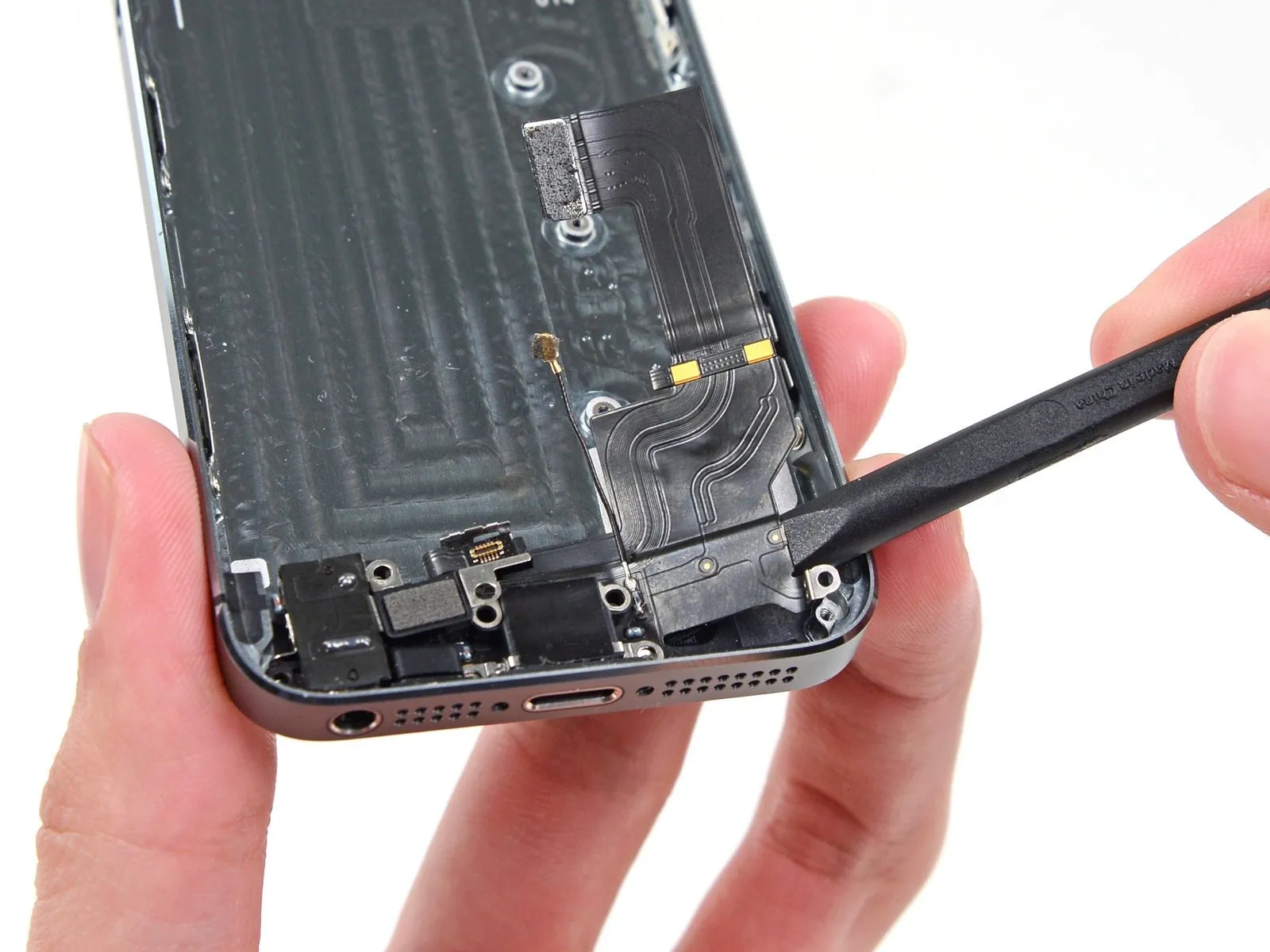
Carefully lift the antenna cable connector from its corresponding socket on the logic board using the pointed end of a spudger.
Step 28


Carefully separate the connector securing the rear camera cable to the logic board's socket using the flat spudger.
Step 29

Carefully detach any adhesive tape securing the camera flash bracket.
Step 30

Using the appropriate screwdriver, detach the logic board by unscrewing all listed fasteners.
A Phillips head screw, size #000 and measuring 2.4 millimeters.
The logic board's metal contact is secured by this screw; it's positioned under a plastic bracket, and if you observe it becoming dislodged, follow this procedure to detach it.
Use two Phillips head screws, size #000 and measuring 2.3 mm.
Use three screws, each measuring 2.8 millimeters in diameter.
A standoff screw, measuring 2.9 millimeters in diameter and constructed from a non-magnetic material, is required.
To detach standoff screws, utilize a standoff screwdriver or bit specifically designed for this purpose.
If a dedicated tool isn't available, a small flathead screwdriver can be carefully substituted; however, exercise heightened awareness to prevent slippage and potential harm to nearby parts.
Step 31


Carefully insert a plastic opening tool beneath the logic board to create sufficient space for a finger grip, allowing you to gently raise it.
Step 32

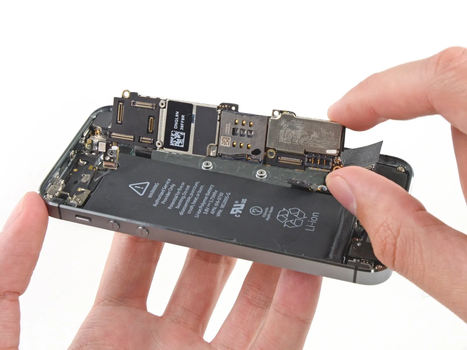

Carefully move the logic board outward, creating a small gap between it and the rear-facing camera assembly.
Before detaching the logic board, remember that an antenna cable secures it to the rear of the device.
Carefully rotate the logic board so that it faces the battery, pivoting it in a manner similar to turning a page.
Before detaching the logic board, remember that an antenna cable secures it to the rear of the device.
Carefully rotate the logic board so that it faces the battery, pivoting it in a manner similar to turning a page.
Step 33


Employing the flat spudger tip, carefully separate the antenna cable connector from the logic board's rear surface.
Carefully detach the iPhone's logic board.
Carefully detach the iPhone's logic board.
Step 34


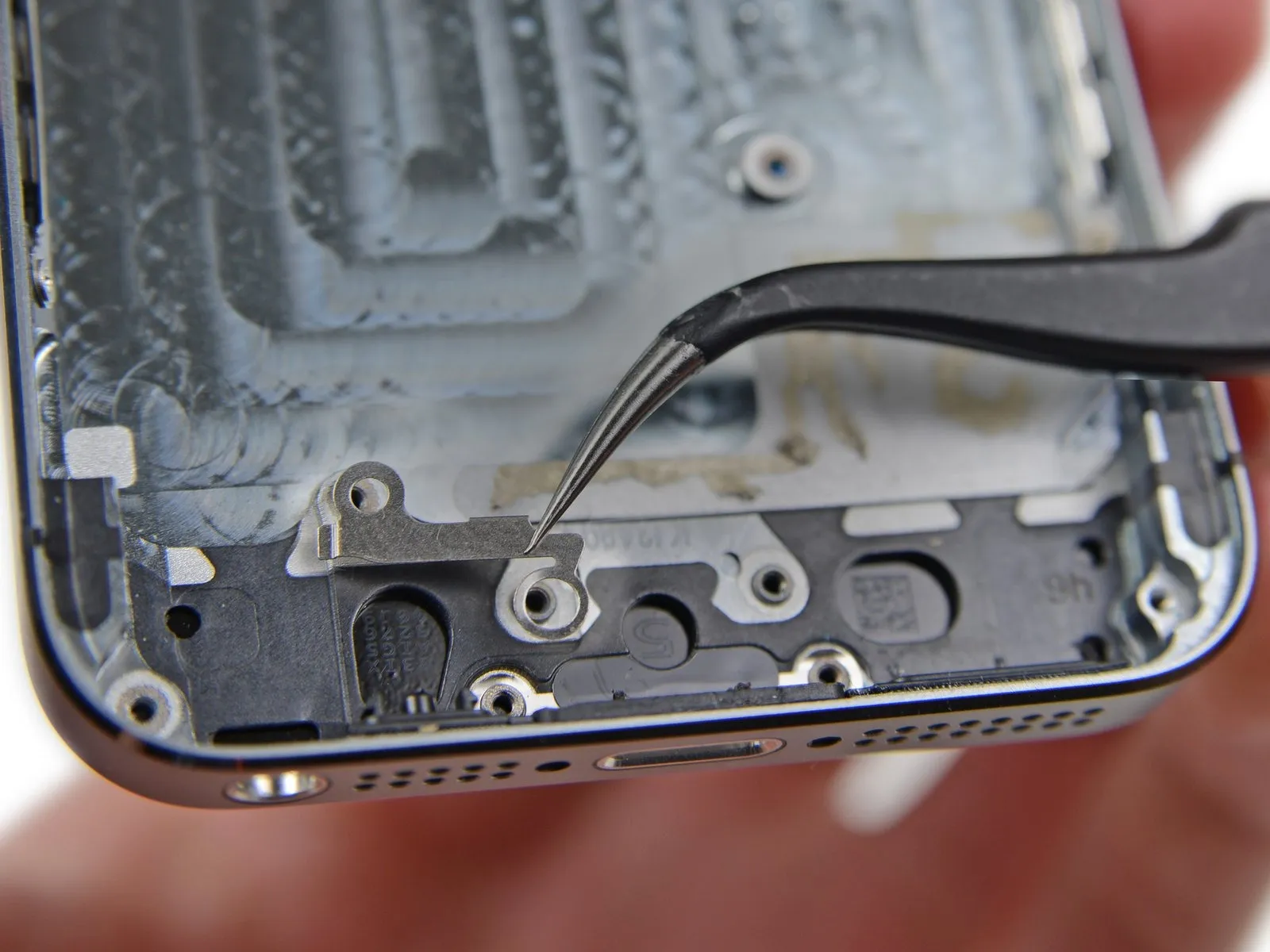
The metal plate situated close to the rear camera is currently detached and risks becoming completely dislodged.
To prevent loss of the tiny plate, detach it and place it in a safe location for safekeeping during the repair process.
Carefully detach the plate located under the bracket on the left side of the rear camera using tweezers.
Ensure the plate's small tab aligns to the right side and its longest, flat surface contacts the phone's upper surface during reassembly.
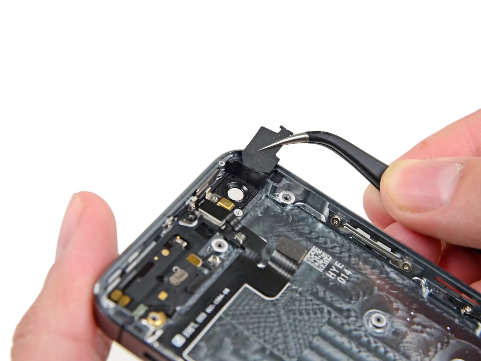
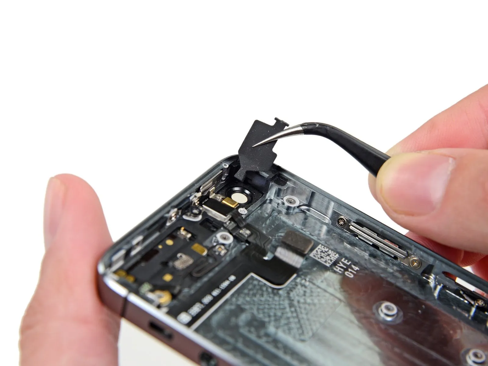
Step 35 | Rear Facing Camera


Carefully use tweezers to pivot the rubber camera cover away from its retaining clip and outward, towards the rear case exterior.
Avoid complete detachment of this cover; it's integrated with the rear case and should be opened, not separated.
Avoid complete detachment of this cover; it's integrated with the rear case and should be opened, not separated.
Step 36


Carefully detach the rear case to access and remove the camera module.
To ensure proper connection during reassembly, form the camera cable into a U-shaped curve so it can be positioned correctly behind the logic board.
To ensure proper function and prevent damage, substitute a displaced rubber camera bumper with a new one prior to reassembling the iPhone.
To ensure proper connection during reassembly, form the camera cable into a U-shaped curve so it can be positioned correctly behind the logic board.
To ensure proper function and prevent damage, substitute a displaced rubber camera bumper with a new one prior to reassembling the iPhone.
Step 37 | Camera Bracket

Using a Phillips #000 screwdriver, detach the rear camera bracket by unscrewing the two 1.6 mm screws that hold it in place.
Step 38
Detach the camera bracket, which secures the rear camera assembly, from the back of the rear case.
Step 39
Carefully detach the rubber bumper, positioned on the camera housing.
Step 40 | Battery

Using a spudger, gently lift the battery adhesive tab by inserting the tool's tip into the opening located close to the headphone jack.
Gently raise the tab a small amount, then employ the spudger to release it from its housing.
Gently raise the tab a small amount, then employ the spudger to release it from its housing.
Step 41
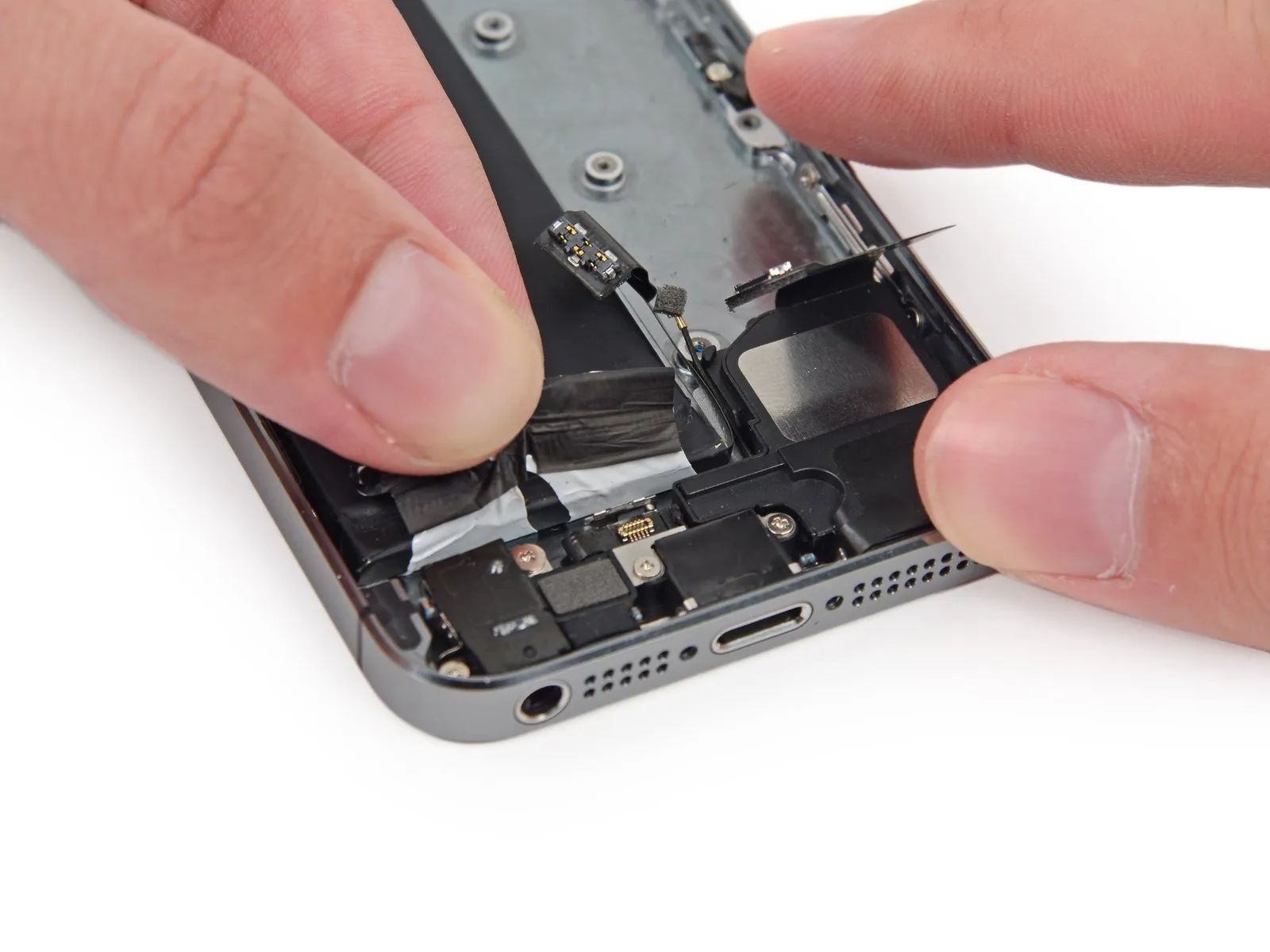


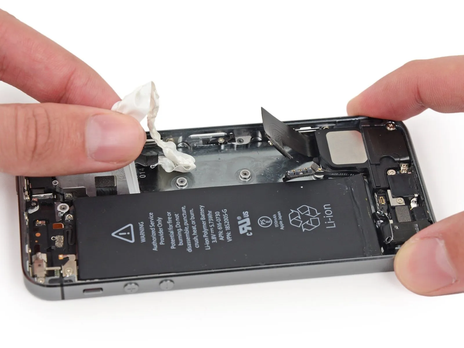
Using a steady motion, detach the battery's adhesive strip by lifting it vertically.
Using a sharp blade, sever the black battery tab by slicing through the adhesive situated on either side of it, effectively detaching the two white adhesive strips.
Using a sharp blade, sever the black battery tab by slicing through the adhesive situated on either side of it, effectively detaching the two white adhesive strips.
Step 42
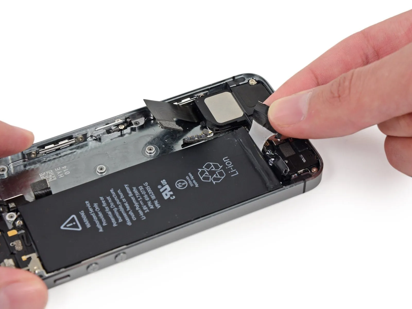

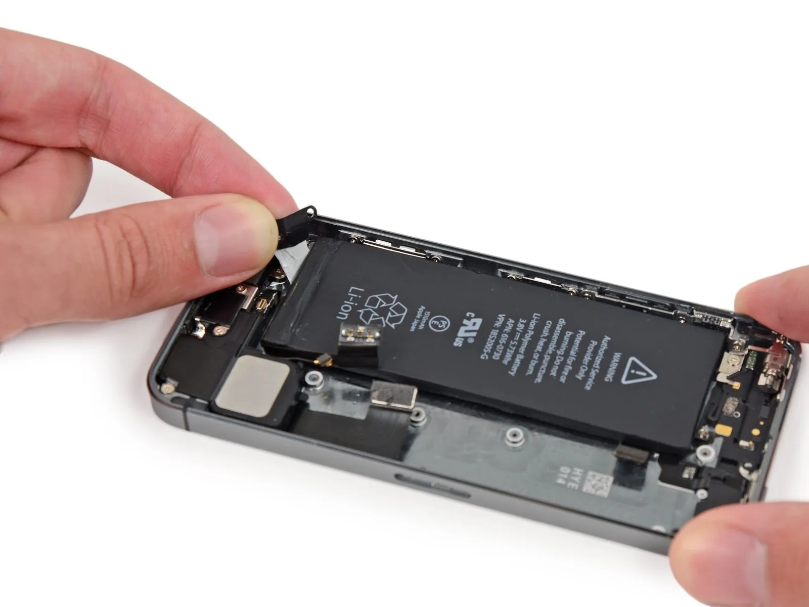
To prevent the strips from adhering and tearing, maintain their flatness and avoid creases throughout this step.
Gently peel one of the battery's adhesive strips downwards, moving it towards the iPhone's lower edge.
To detach the strip, apply consistent, even force while it disengages from the space between the battery and the rear case; ensure the pulling angle remains at 60 degrees or less to optimize the process.
Step 43

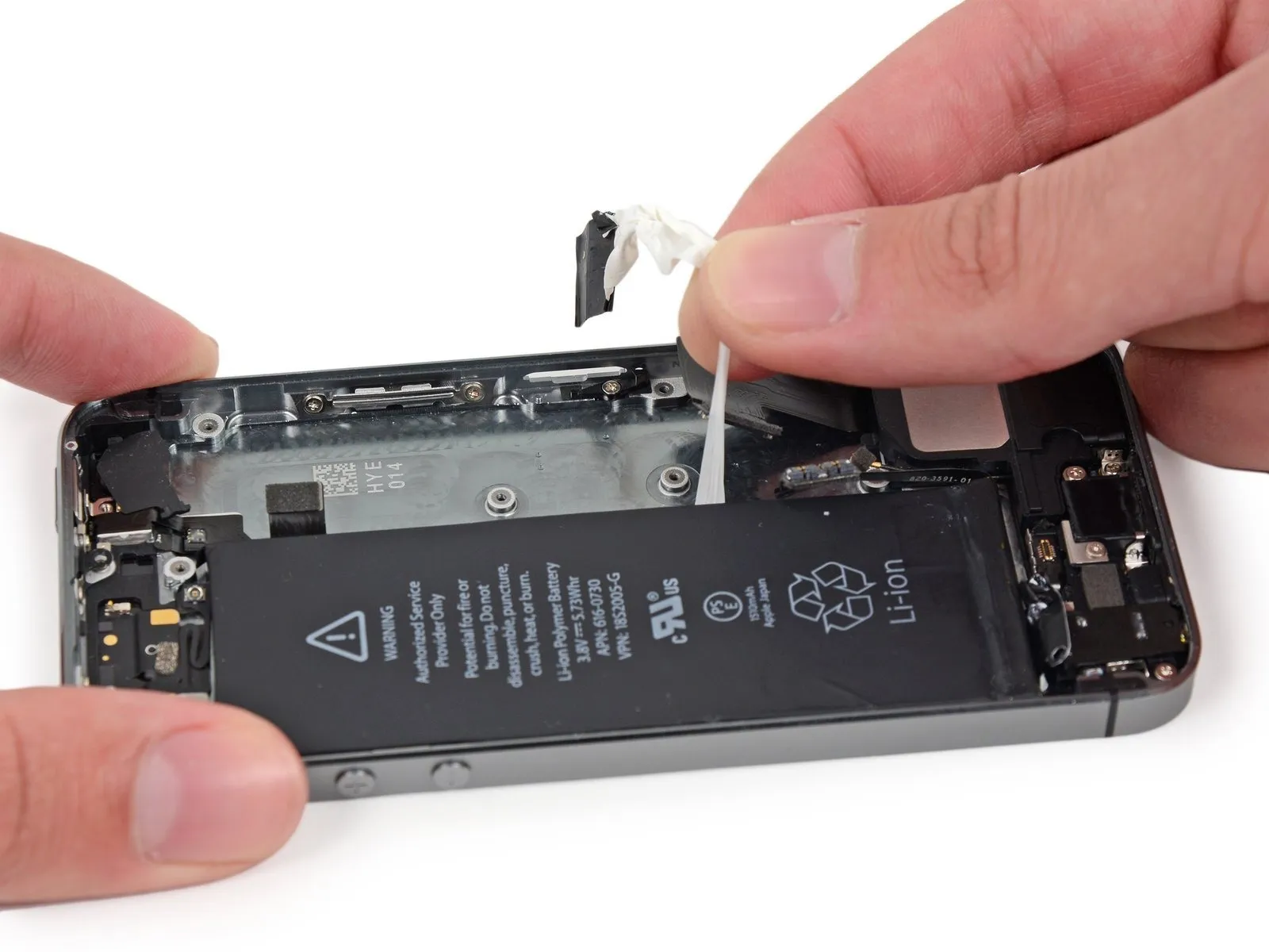
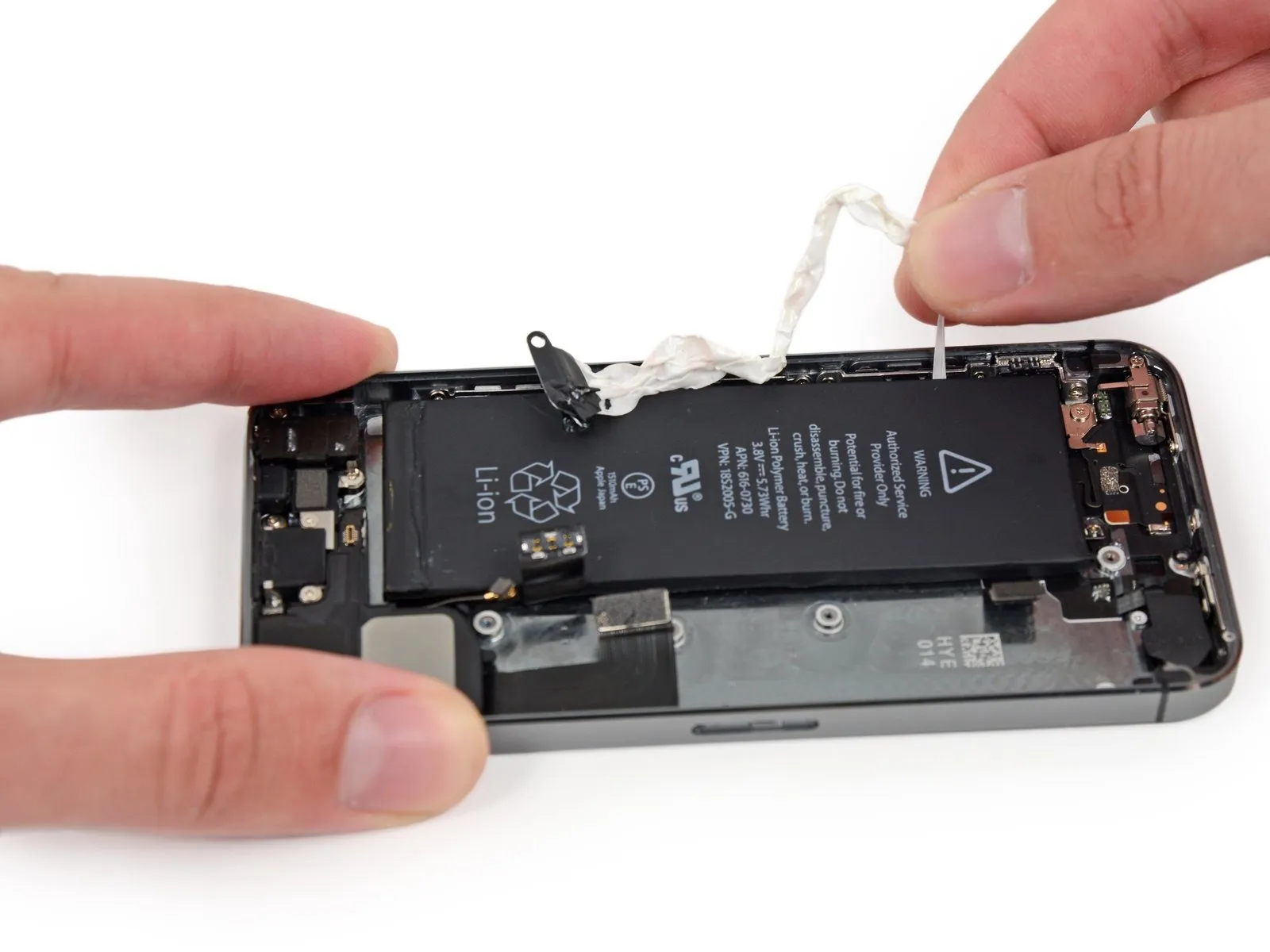
Maneuver the strip along the corner's contour and upward along the battery's vertical surface, exercising caution.
Exercise caution to prevent the ribbon cable from catching on the battery's edges or any other internal iPhone parts.
To release the strip completely, exert continuous tension; it will extend significantly beyond its initial size, and you may need to reposition your grip closer to the battery as you pull.
Step 44

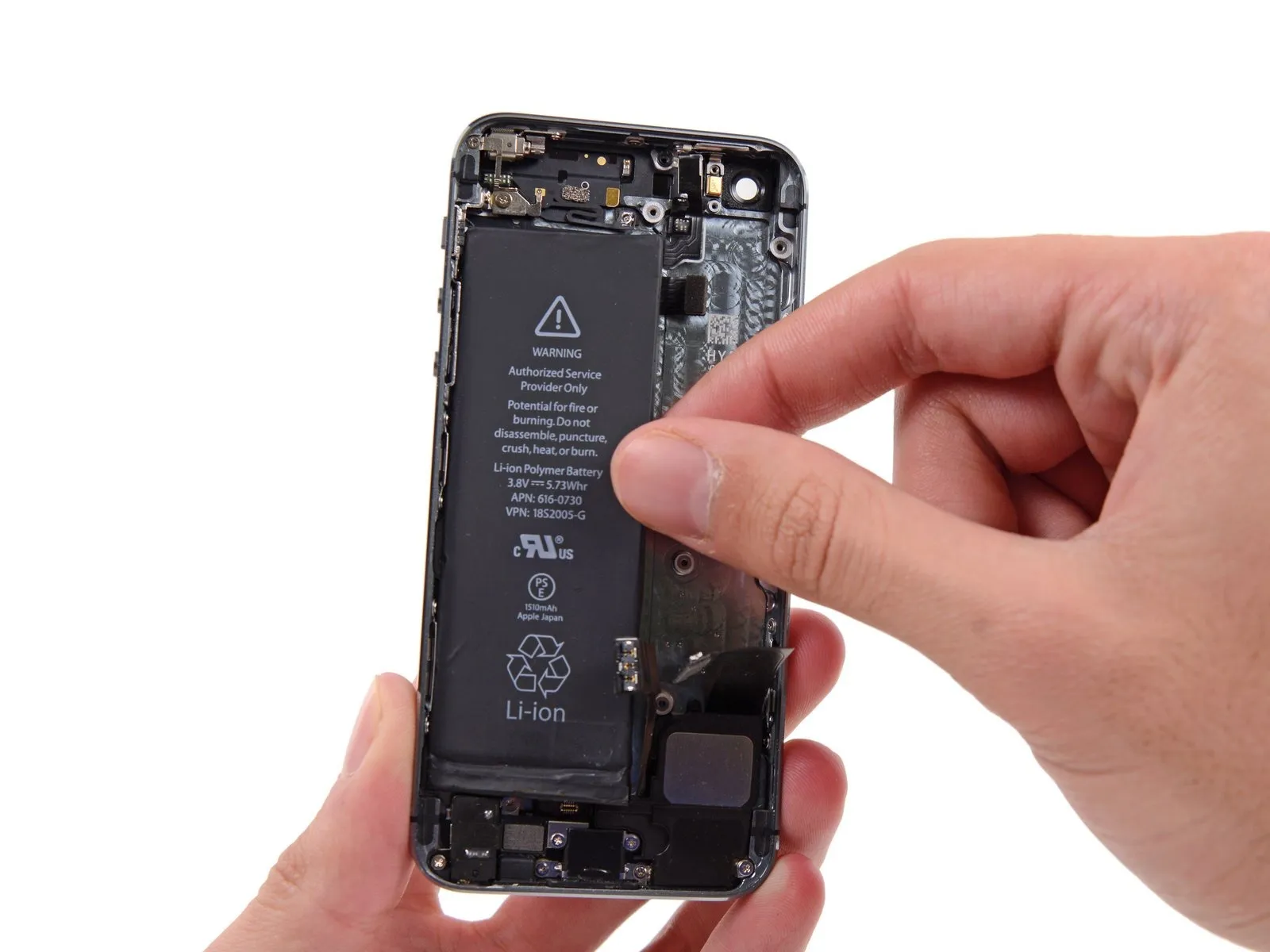
Employ the same procedure to detach the remaining adhesive strip.
Having detached both strips completely, proceed to a later stage of the repair.
Should the adhesive strips beneath the battery tear or become irretrievable, carefully detach any remaining portions before continuing.
Having detached both strips completely, proceed to a later stage of the repair.
Should the adhesive strips beneath the battery tear or become irretrievable, carefully detach any remaining portions before continuing.
Step 45

To free a battery adhered to the rear case after adhesive strip failure, apply heat using either an iOpener or a hair dryer, focusing the warmth on the rear case area immediately behind the battery.
Step 46

Using a plastic card, carefully slide it into the space between the battery’s casing and the iPhone’s rear enclosure.
To prevent battery damage and potential release of hazardous chemicals, maintain a consistently flat position of the card during handling.
Advance the card until the adhesive securing the battery is disrupted.
To prevent battery damage and potential release of hazardous chemicals, maintain a consistently flat position of the card during handling.
Advance the card until the adhesive securing the battery is disrupted.
Step 47
Disconnect the power source by extracting the battery located within the rear case assembly.
To ensure proper battery installation, follow these instructions to substitute the existing adhesive strips with new ones.
To ensure proper battery installation, follow these instructions to substitute the existing adhesive strips with new ones.
Step 48 | Vibrator

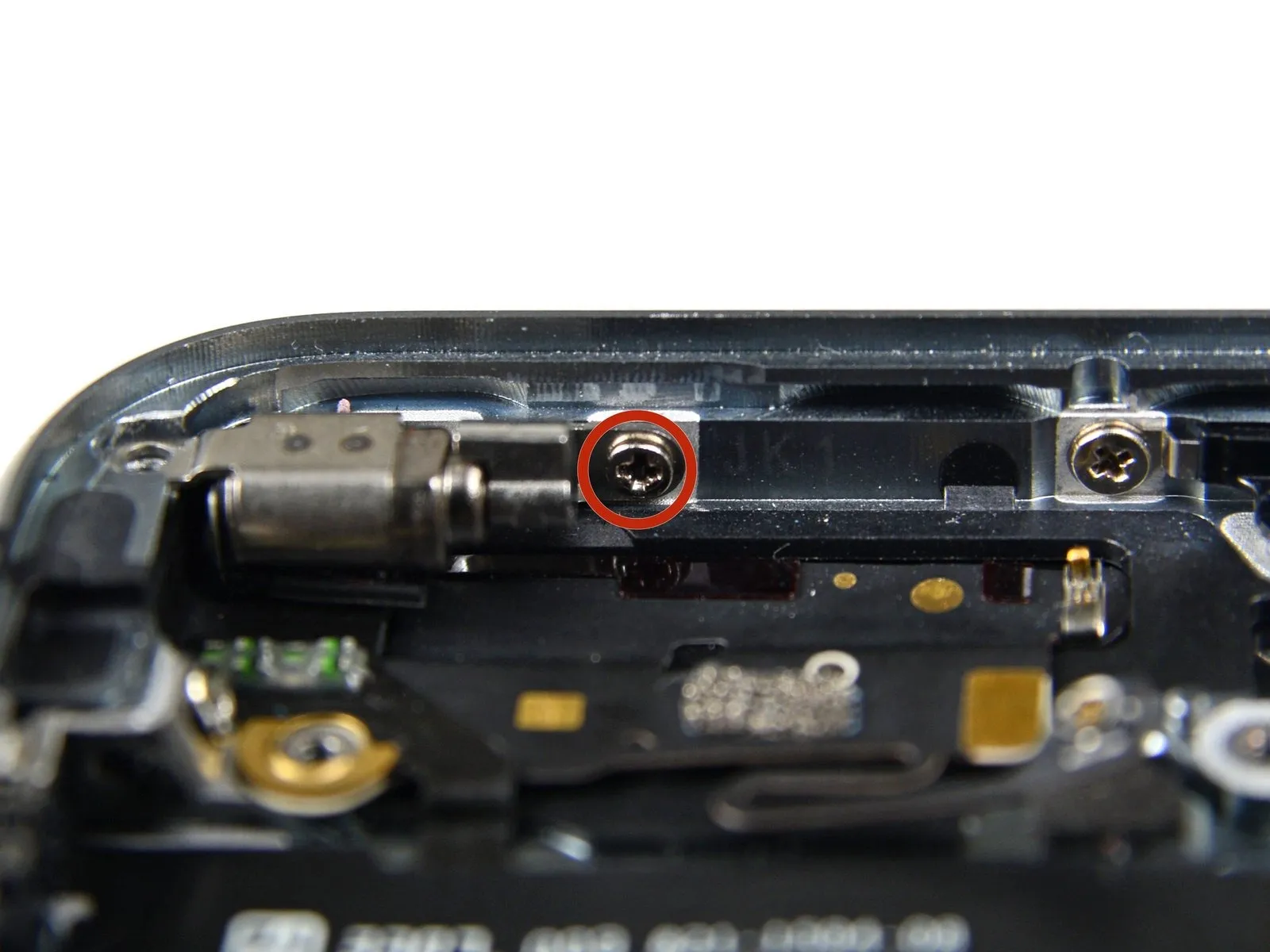
Using a Phillips #000 screwdriver, detach the screws securing the vibrator bracket.
- A screw with a 1.7 mm diameter is required.
- A screw with a 2.5-millimeter diameter is required.
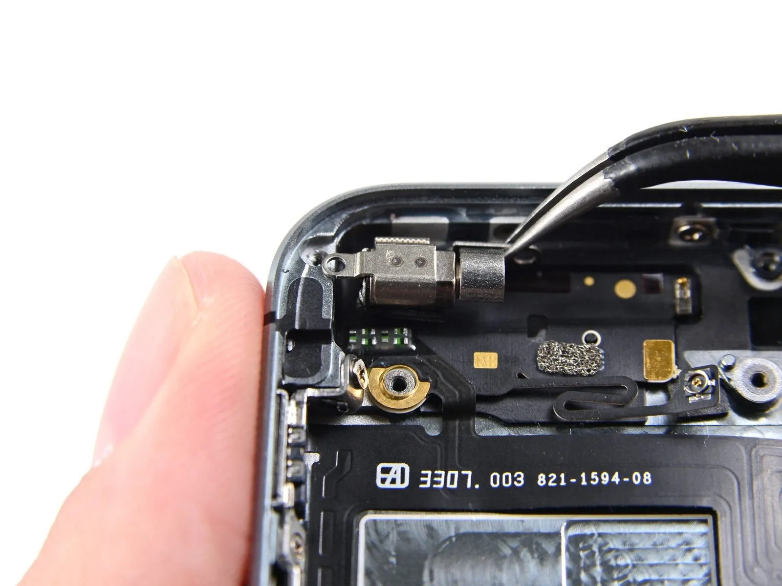
Step 49
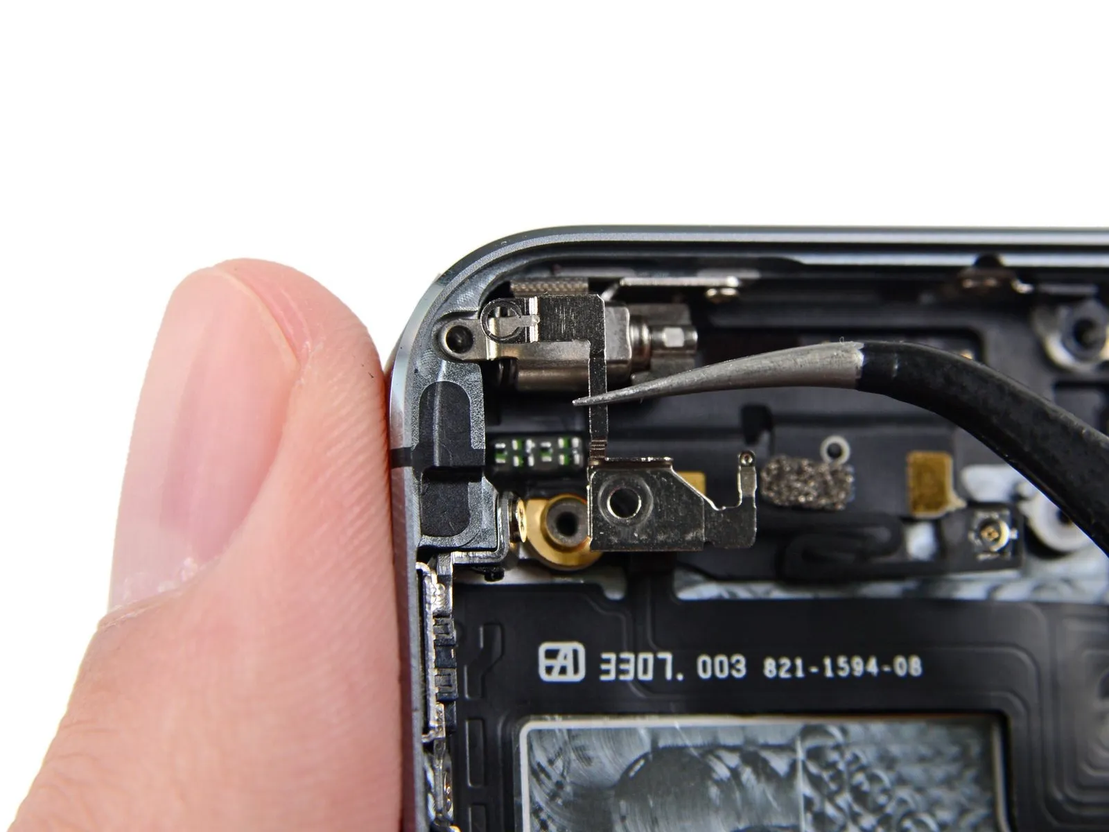
Using tweezers, detach the vibrator bracket.
Step 50
Using a Phillips #000 screwdriver, detach the vibrator from the rear case by unscrewing the 1.7 mm screw that holds it in place.
Step 51
Carefully extract the vibrator from the rear case using tweezers.
Step 52 | Upper Component Cable
Using the appropriate screwdriver, detach the volume button and ringer switch brackets from the rear case by unscrewing the fasteners holding them in place.
- Use a Phillips screwdriver to remove a single screw with a 1.9 mm head.
- Use two Phillips screws, each measuring 1.6 mm.
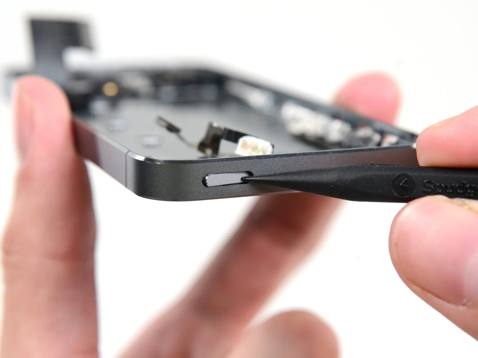
Step 53
Carefully insert the pointed end of a spudger between the ringer switch bracket and the rear case to release it.
Disconnect and detach the ringer switch.
Ensure correct reassembly by positioning the button so its red marking faces upward, and aligning the notch on its rear surface with the corresponding switch on the cable.
Disconnect and detach the ringer switch.
Ensure correct reassembly by positioning the button so its red marking faces upward, and aligning the notch on its rear surface with the corresponding switch on the cable.
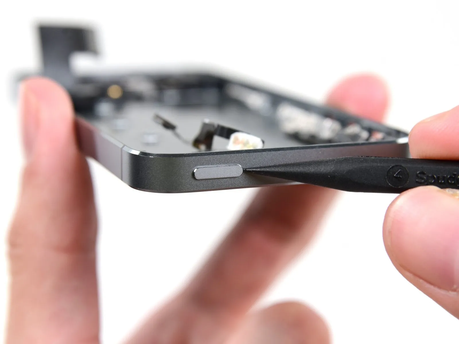
Step 54

Carefully separate the volume button bracket from the rear case's side using a spudger.
Carefully detach the volume buttons.
When putting everything back together, position the volume up button so that it aligns with the opening nearest the ringer switch.
Carefully detach the volume buttons.
When putting everything back together, position the volume up button so that it aligns with the opening nearest the ringer switch.
Step 55
Carefully extract the rubber camera cover, which faces backward, from its recess in the rear case using tweezers.
Step 56

Using a Phillips #000 screwdriver, detach the logic board antenna bracket from the rear case by unscrewing the 1.3 mm screw that holds it in place.
Step 57

Detach the bracket securing the logic board antenna.
Step 58
Using a Phillips #000 screwdriver, detach the bracket that holds the contact clip and power/sleep button by unscrewing the single 2.1 mm screw.
Step 59
Carefully detach the contact clip from the iPhone, ensuring no damage occurs.
Ensure the bracket is positioned correctly, fitting snugly between the rear camera flash and the case's upper border.
Ensure the bracket is positioned correctly, fitting snugly between the rear camera flash and the case's upper border.
Step 60

Using a spudger with a flat tip, carefully separate the upper component assembly cable from the rear case by gently inserting the spudger underneath it.
Step 61


Using the spudger's flat edge, carefully slide it between the cable and the device housing, focusing on the area close to the volume control buttons.
Step 62
Carefully disengage the adhesive holding the vibrator contact area of the upper assembly cable to the rear case using a spudger tip.
Gently use the spudger tip to dislodge the flash assembly from its opening in the rear case, if it remains secured.
Gently use the spudger tip to dislodge the flash assembly from its opening in the rear case, if it remains secured.
Step 63

Carefully disengage the microphone component from the casing by gently prying with a spudger tip.
Step 64
Carefully maneuver the power/sleep button bracket clear of the device housing using tweezers.
Step 65

Gently depress the power/sleep button on the phone's housing a small amount by applying pressure with a spudger tip.
Carefully extract the button using tweezers.
Ensure the button is correctly positioned during reassembly; the two "L" markings must face downwards, and the metal bar should be bent over the button's upper surface.
Carefully extract the button using tweezers.
Ensure the button is correctly positioned during reassembly; the two "L" markings must face downwards, and the metal bar should be bent over the button's upper surface.
Step 66
Carefully detach the hinge of the power and sleep button bracket from its securing post within the iPhone.
Step 67
Carefully detach the iPhone's upper assembly.
Due to its numerous fragile terminations and susceptibility to tearing, handle this cable with extreme care. Should you feel any opposition while attempting to raise the cable, cease the action without delay. Use a spudger to gently separate the cable from its surroundings across its entire length, then attempt lifting once more.
Due to its numerous fragile terminations and susceptibility to tearing, handle this cable with extreme care. Should you feel any opposition while attempting to raise the cable, cease the action without delay. Use a spudger to gently separate the cable from its surroundings across its entire length, then attempt lifting once more.
Step 68 | Rear Case
Using a Phillips #000 screwdriver, detach the listed screws.
Use two fasteners with a diameter of 2.9 millimeters.
Use two fasteners with a diameter of 1.5 millimeters.
Measure 3.1 millimeters.
Employ a 3.6-millimeter measurement.
A measurement of 3.4 millimeters is required.
Use two fasteners with a diameter of 2.9 millimeters.
Use two fasteners with a diameter of 1.5 millimeters.
Measure 3.1 millimeters.
Employ a 3.6-millimeter measurement.
A measurement of 3.4 millimeters is required.
Step 69
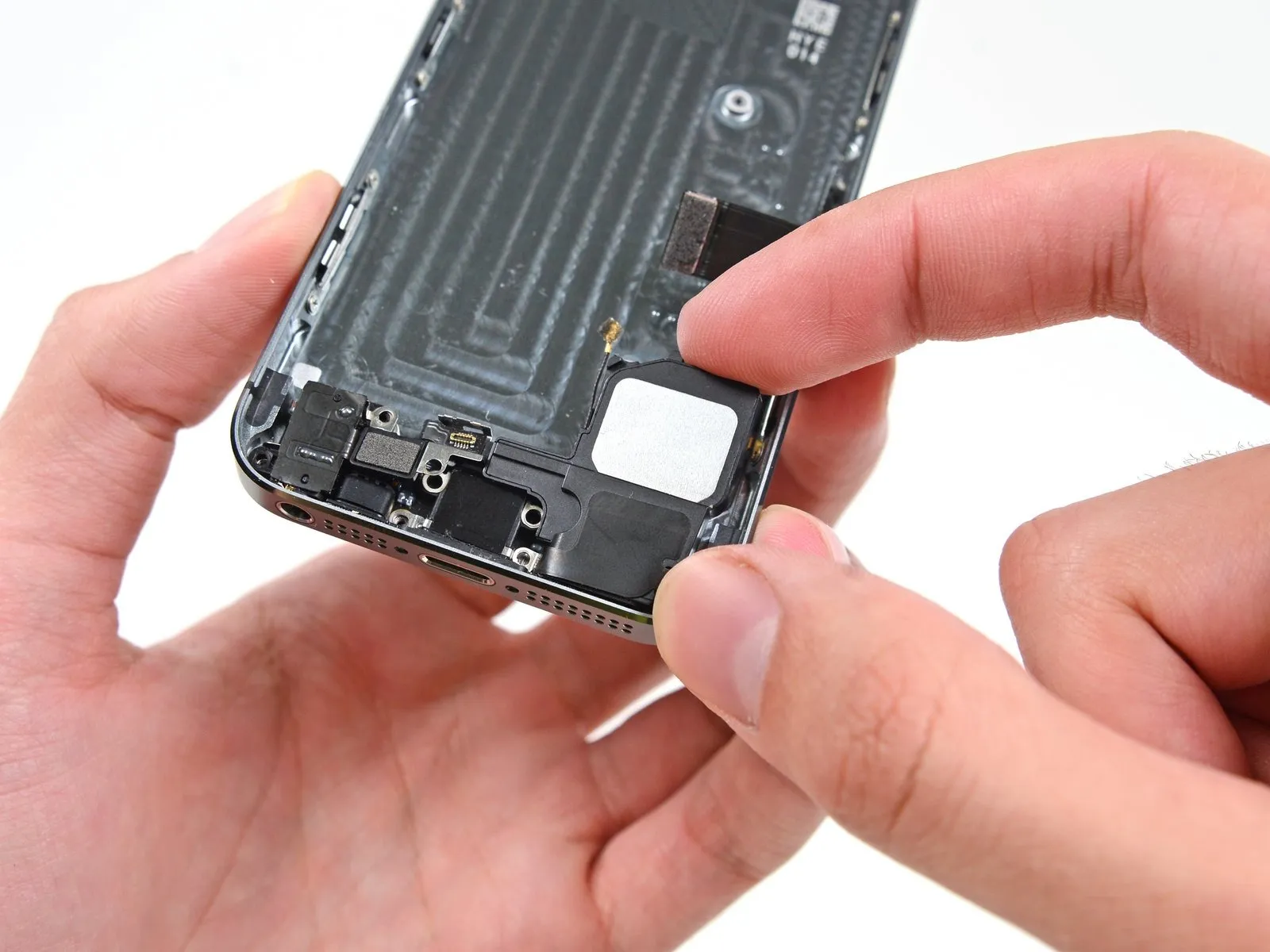
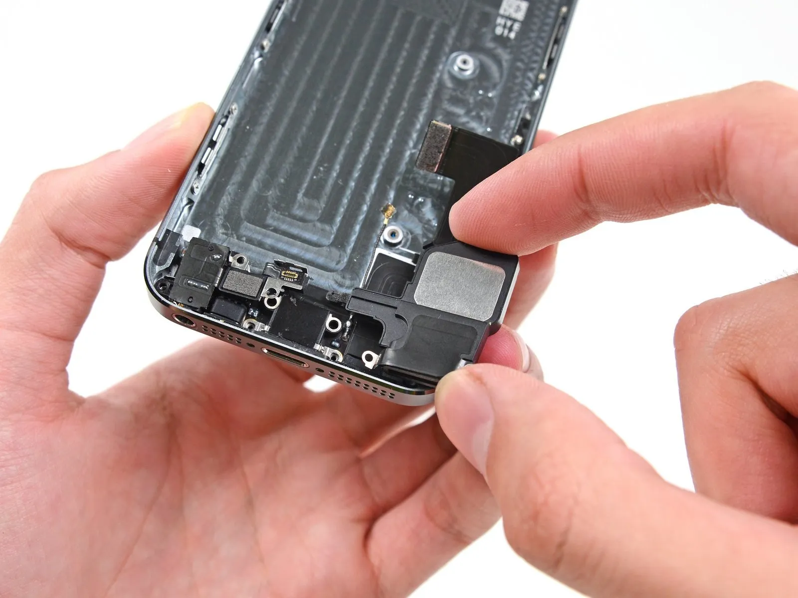
Carefully disengage the speaker from the rear case by raising it vertically.
Step 70
Using a spudger, carefully insert its flat tip beneath the lightning connector cable assembly on the right side, releasing it from the rear case.
Step 71

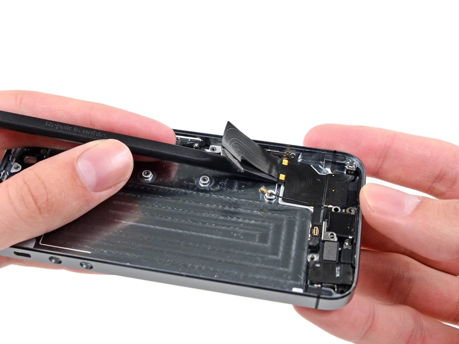
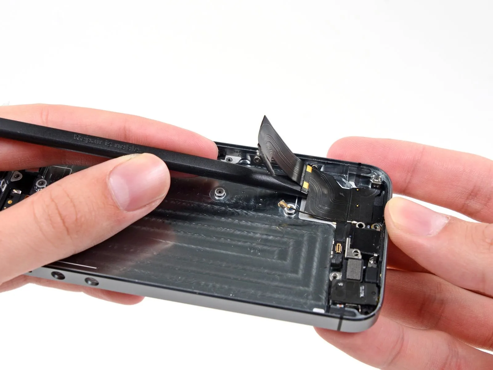
Using a spudger, carefully separate the lightning cable assembly by gently sliding the tool beneath the port's components.
Step 72

Detach the lightning cable assembly from the rear case.
Step 73

Following removal of the Lightning connector assembly, carefully inspect for a bracket and washer, both small metal components, which could become detached.
Carefully remove the components and store them securely to prevent damage.
Carefully remove the components and store them securely to prevent damage.