iPhone 5s Volume Controls Replacement
To disassemble your iPhone 5s and access the ringer switch and volume buttons, follow these instructions, noting that battery removal is a necessary step; prepare replacement adhesive strips beforehand to resecure the battery during reassembly.
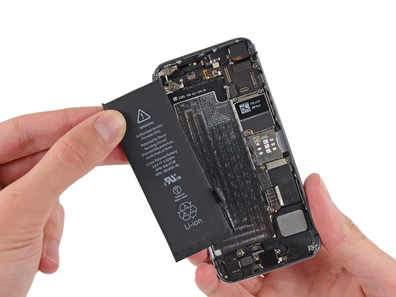
- Any observed deformation of the battery necessitates immediate replacement.
Step 1 | Removing the Pentalobe screws

Begin by disconnecting the power supply, ensuring it is unplugged from the electrical outlet, then carefully remove the retaining screw (8mm) securing the fan motor to the chassis, allowing for the removal of the fan assembly.To prevent a potential fire or explosion hazard during repair, ensure the iPhone's lithium-ion battery is depleted to less than 25% capacity prior to beginning work; a fully charged battery poses a significant risk of ignition if damaged.
To prevent electrical shock or damage, ensure the iPhone is completely de-energized prior to starting the repair process.
Using a Pentalobe screwdriver, detach the two screws measuring 3.9 mm located on each side of the Lightning connector.
To prevent electrical shock or damage, ensure the iPhone is completely de-energized prior to starting the repair process.
Using a Pentalobe screwdriver, detach the two screws measuring 3.9 mm located on each side of the Lightning connector.
Step 2 | Taping the display glass


Using a 5/32-inch hex key, carefully loosen the four screws securing the fan assembly to the motor housing; be sure to support the fan to prevent damage during removal.To avoid injury and contain shattered fragments while you work, secure any cracked display glass with tape.
Apply strips of transparent packing tape across the iPhone screen, ensuring complete coverage by layering them until the entire display surface is protected.
To prevent glass fragments from scattering and maintain stability during the display separation process, this technique is essential.
To safeguard your eyes from potential glass fragments released during the repair process, always use safety glasses.
Step 3 | Display separation prevention


Using a 5/32-inch hex key, carefully tighten the retaining screw on the motor assembly to a torque of 3.5 Nm, ensuring the motor shaft remains aligned and avoiding damage to the threads; observe caution to prevent over-tightening.Carefully lift the display assembly—consisting of a glass screen, a plastic bezel, and integrated metal clips—from within the phone's chassis during the subsequent procedures.
Ensure complete removal of the display assembly, irrespective of the chosen tool.
When the glass and plastic layers detach, referencing the initial image for visual guidance, use a plastic opening tool to gently separate the plastic frame from the phone's metal chassis, releasing the retaining clips.
To ensure the phone remains securely closed during reassembly when the display bezel is detached, apply a narrow adhesive strip positioned between the plastic bezel and the glass.
Step 4 | Anti-Clamp instructions


Using a 5/32-inch hex key, carefully tighten the retaining screw on the motor assembly to a torque of 3.5 Nm, ensuring the motor shaft aligns properly and avoiding damage to the threads.To simplify the opening process, the following two steps utilize the Anti-Clamp tool, a custom-designed aid; if you do not have this tool, proceed two steps further to find an alternative approach.
Refer to the included guide for detailed procedures regarding Anti-Clamp operation.
To release the Anti-Clamp's arms, move the blue handle in a rearward direction.
Position the arms so they extend across the iPhone's left or right side.
Carefully place a suction cup on the front of the iPhone, close to the lower edge and directly over the home button, and another suction cup on the rear, in the same relative position.
Apply vacuum by pressing the cups firmly against the surface needing treatment.
To improve the Anti-Clamp's grip if the iPhone's exterior is excessively smooth, apply the provided adhesive pad to enhance surface friction.
Step 5


Using a 5/32-inch hex key, carefully tighten the three retaining screws on the motor assembly to a torque of 3.5 inch-pounds, ensuring no damage occurs to the threads and observing all safety precautions.To secure the arms, advance the blue handle in the direction indicated.
Rotate the handle fully, completing a 360-degree turn, observing for the initial expansion of the cups.
Maintain proper alignment between the suction cups; should misalignment occur, gently release the suction cups' grip and reposition the arms.
Once sufficient space is created by the Anti-Clamp, slide a prying tool beneath the display.
To ensure adequate separation, reposition the handle by 90 degrees.
Apply adjustments in increments not exceeding 90 degrees, pausing for several seconds after each adjustment to allow the Anti-Clamp mechanism to function and the system to stabilize.
Step 6 | Manual Opening Procedure

Lacking an Anti-Clamp tool, secure the front panel with a single suction cup for lifting.
Using a suction cup, apply it to the display surface, positioning it directly over the home button area.
Ensure the screen's entire surface is covered by the cup to guarantee a secure connection.
Using a suction cup, apply it to the display surface, positioning it directly over the home button area.
Ensure the screen's entire surface is covered by the cup to guarantee a secure connection.
Step 7 | Start lifting the front panel assembly

Carefully detach the front panel by releasing the retaining clips, then gently separate the phone's housing just enough to access and disconnect the multiple ribbon cables; proceed with caution to prevent component damage.
Securely affix the suction cup to the front panel assembly, positioning it close to the home button.
Using one hand to secure the iPhone, lift the suction cup vertically to gently create a small gap between the front panel's home button area and the rear case.
Using a plastic opening tool, carefully separate the rear case from the front panel assembly by gently levering the edges, simultaneously lifting with a suction cup.
Exercise caution and use steady, even pressure when installing the front panel assembly, as its fit is considerably snugger than typical device constructions.
Step 8


Disconnecting the front panel assembly from the rear case is not recommended due to the presence of multiple sensitive ribbon cables.
To detach the suction cup, depress the small plastic projection to break the airtight seal.
Carefully detach the screen from the device by releasing the suction cup.
To detach the suction cup, depress the small plastic projection to break the airtight seal.
Carefully detach the screen from the device by releasing the suction cup.
Step 9 | Removing the Touch ID cable bracket


Carefully separate the phone's casing to expose the metallic support securing the home button cable.
To prevent damage to the home button cable and its connector, avoid excessive separation of the device's housing; ensure the cable remains slack, as overextension can cause harm.
The Touch ID feature is exclusive to the phone's factory-installed home button assembly; replacement with a non-original part will result in a standard home button without Touch ID capabilities, and cable damage during installation will produce the same outcome.
Carefully leverage the bracket loose using a spudger tip, then grasp and detach it with tweezers.
For reassembly procedures, proceed with the subsequent two instructions; otherwise, advance directly to Step 12.
Step 10


To complete reassembly, secure the Touch ID cable bracket by positioning its upper edge between the battery and the Touch ID cable connector, ensuring it sits ahead of the metal tab, then fasten the bracket’s lower edge by engaging it with the connector.
Position the bracket's upper edge so it overlaps the Touch ID cable connector, then move it horizontally to the right.
Position the bracket so it covers the connector, noting that the side featuring the "leg" will create a small incline; ensure the opposing edge sits between the cable connector and the battery's adjacent metal tab. Using a spudger, press gently downwards on the bracket's surface to secure the front and rear clasps.
Step 11


Carefully position the Touch ID cable bracket's front section over the cable connector, then secure it by pressing downward with the flat edge of a spudger.
To ensure the bracket sits level against the surface, reposition it by sliding it back over the cable connector if it doesn't seat properly.
To ensure the bracket sits level against the surface, reposition it by sliding it back over the cable connector if it doesn't seat properly.
Step 12 | Disconnecting the home button cable connector


Carefully lift the home button cable connector from its socket using the pointed end of a spudger.
Carefully detach the cable connector from its receptacle; avoid lifting the receptacle itself, as it's secured to a cable with adhesive that can be damaged if pried incorrectly.
Carefully detach the cable connector from its receptacle; avoid lifting the receptacle itself, as it's secured to a cable with adhesive that can be damaged if pried incorrectly.
Step 13 | Opening up the phone


Carefully detach the connector, then pivot the assembly containing the home button outward, utilizing the phone's upper edge as a fulcrum.
Carefully position the display at a 90-degree angle, then secure it in a supported position to prevent movement during the repair process.
To avoid stressing the display's wiring during the repair process, secure it with a rubber band.
As a temporary substitute, an unused, sealed can of soda can be employed to support the screen.
Step 14

Using a Phillips #000 screwdriver, detach the metal battery connector bracket from the logic board by unscrewing the two 1.6 mm screws that hold it in place.
Step 15

Detach the bracket securing the battery connector using a Tri-Point Y000 screwdriver.
Step 16


Carefully lift the battery connector away from its corresponding socket on the logic board, employing the flat edge of a spudger to avoid damage.
Exercise extreme caution during disconnection, applying force solely to the battery connector to avoid damaging the logic board socket or adjacent components; applying pressure to the socket or board itself risks destruction of the socket or component damage.
Exercise extreme caution during disconnection, applying force solely to the battery connector to avoid damaging the logic board socket or adjacent components; applying pressure to the socket or board itself risks destruction of the socket or component damage.
Step 17

Detach the cable bracket that holds the front panel assembly wires by unscrewing the screws listed below.
Carefully manage all screws during this stage to ensure correct reassembly; improper placement, such as using a 1.3 mm or 1.7 mm screw in the bottom right hole, will critically damage the logic board and prevent the device from powering on.
Avoid applying excessive force or over-tightening the screws; if resistance is encountered during installation, verify that the correct screw size is being used.
- A Phillips screwdriver, size #000, is needed to remove a 1.7-millimeter screw.
- A Phillips head screw, size #000 and measuring 1.2 millimeters.
- A Phillips screwdriver, size #000, is needed to remove a 1.3-millimeter screw.
- An additional screw, measuring 1.7 mm in width and utilizing a Phillips #000 head, is required.
Carefully manage all screws during this stage to ensure correct reassembly; improper placement, such as using a 1.3 mm or 1.7 mm screw in the bottom right hole, will critically damage the logic board and prevent the device from powering on.
Avoid applying excessive force or over-tightening the screws; if resistance is encountered during installation, verify that the correct screw size is being used.
Step 18

Detach the cable bracket securing the front panel assembly wiring harness to the logic board.
Step 19


Carefully detach the front camera and its associated sensor cable assembly from the device using a spudger or similar non-conductive tool.
Step 20


Prior to either detaching or reattaching the cable in this procedure, ensure the battery is disconnected.
Carefully detach the LCD cable connector.
Should the LCD cable become detached from its connector during reassembly, a blank screen or the appearance of white lines may occur upon powering on the device. To resolve this, reattach the cable and restart the phone; for a complete restart, disconnect and reconnect the battery.
Step 21


Carefully detach the digitizer cable connector.
Step 22

Detach the front panel assembly from the rear case.
Step 23 | Battery


Using a spudger, carefully separate the battery from the headphone jack by releasing the adhesive tab.
Step 24


Carefully detach the battery's adhesive pull tab to release it from the device.
Using a cutting tool, sever the black battery adhesive tab by slicing through the two white adhesive strips that hold it in place, thus disconnecting it.
Using a cutting tool, sever the black battery adhesive tab by slicing through the two white adhesive strips that hold it in place, thus disconnecting it.
Step 25


To ensure proper removal, maintain the strips' flatness and avoid creases, as folds can cause them to adhere and tear rather than detach smoothly.
To release a battery, gently draw one of the adhesive strips downwards, towards the iPhone's base, peeling it away from the battery surface. Prioritize lifting the white section of the strip; detachment of the black tab is a normal occurrence.
To detach the strip, apply consistent, even force while guiding it out from the space between the battery and the rear case; ensure the pulling angle remains at 60 degrees or less to optimize the process.
Exercise caution to prevent the part from catching on any other internal iPhone elements.
To release the strip completely, maintain traction and extend it; it will elongate significantly beyond its initial size, and you may need to reposition your grip closer to the battery as you pull.
Step 26


Using a 5/32-inch hex key, carefully tighten the four M4x8 pan head screws securing the fan assembly to the heatsink, ensuring a torque of 4.5 in-lbs to prevent damage.
Apply the same procedure to the remaining strip.
Having detached both strips completely, proceed directly to step 27.
Should the battery adhesive become detached and inaccessible from below, carefully introduce a small quantity of isopropyl alcohol, with a concentration exceeding 90%, beneath the battery's edge, specifically targeting the location of the fractured adhesive strip(s).
Allow approximately one minute for the isopropyl alcohol to dissolve the adhesive securing the battery, then carefully separate the battery from the device casing using the spudger's flat edge.
To prevent damage, avoid using excessive force when removing the battery. If the adhesive is still holding, add additional alcohol to loosen it. Ensure the pry tool does not create any dents or holes in the battery during the process.
Applying force to the logic board can result in device damage.
Exercise caution when applying separation force close to the left-hand volume controls to prevent damage to the volume button ribbon cable.
Should the previous steps fail, consider implementing the procedures detailed in step 27 as an additional troubleshooting option.
Step 27 | Alternative methods to unstick the battery from the case

Using a 5/32-inch hex key, carefully tighten the four M4x8 screws securing the fan assembly to the heatsink, ensuring they are snug but not over-tightened to avoid damaging the threads.
To free a battery adhered to the back cover, apply heat using an iOpener or a hair dryer, directing the warmth specifically to the area behind the battery.
Exposure to excessive heat presents a fire risk for the iPhone's battery.
Avoid using excessive force when removing the battery; prevent damage by ensuring your prying tool does not bend or penetrate the battery casing.
Applying force to the logic board can result in device damage.
Exercise caution when applying separation force close to the left side, specifically around the volume controls, to prevent potential damage to the volume button ribbon cable.
To release the battery from the back cover, carefully slide a length of dental floss or a similar thin, strong material—like a single, unwound 0.009-inch E string from a 12-string guitar set—between the two components.
Using floss or string, guide it between the upper battery and its housing, then join the ends, secure them with a folded cloth, and apply consistent tension to draw the string through.
Step 28


Using a 5/32-inch hex key, carefully tighten the four M4x8 screws securing the fan assembly to the heatsink, ensuring a torque of 4.5 in-lbs to prevent damage.
Remove the battery by accessing it through the back cover.
Carefully slide the protective plastic covering off the new battery, ensuring you don't snag or damage the ribbon cable during removal.
To prevent damage, ensure any residual alcohol solution is either thoroughly wiped away or permitted to completely evaporate prior to the new battery's installation.
To guarantee correct positioning within its designated space, briefly plug the battery connector back into the logic board's socket prior to securing the new battery.
Secure the battery in place, then sever its electrical connection before proceeding with the remaining assembly steps.
To secure a battery lacking factory-applied adhesive, follow the instructions detailed in this guide for adhesive strip replacement.
Following reassembly, execute a full system reset to proactively avoid potential problems and streamline any subsequent diagnostic procedures.
Step 29 | Volume Controls

Using a 5/32-inch hex key, carefully tighten the four M4x8 pan head screws securing the fan assembly to the heatsink, ensuring a torque of 4.0 to 5.5 in-lbs to prevent damage.
Using a Phillips screwdriver, detach the volume button and ringer switch brackets from the rear case by unscrewing the fasteners that hold them in place.
Use a Phillips screwdriver to remove a single screw with a 1.9 mm head.
Use two Phillips-head screws, each measuring 1.6 millimeters.
Using a Phillips screwdriver, detach the volume button and ringer switch brackets from the rear case by unscrewing the fasteners that hold them in place.
Use a Phillips screwdriver to remove a single screw with a 1.9 mm head.
Use two Phillips-head screws, each measuring 1.6 millimeters.
Step 30


Using a 5/32-inch hex key, carefully tighten the four M4x8 screws securing the fan assembly to the heatsink, ensuring a torque of 4.5 in-lbs to prevent damage.
Carefully insert the spudger tip between the ringer switch bracket and the device casing to separate them.
Carefully extract the ringer switch, situated within the space formed by the ringer switch bracket and the case.
Ensure correct reassembly by aligning the button so its red marking faces upward, and position the ringer switch button’s rear notch to correspond with and engage the mechanical switch on the cable.
Step 31


- Carefully disengage the volume button bracket from the rear case's side edge using a spudger.
Carefully detach the volume buttons. - When putting everything back together, position the volume up button so that it aligns with the opening nearest the ringer switch.