iPhone 6 Rear Case Replacement
Follow these instructions to remove and substitute the iPhone 6’s back cover.
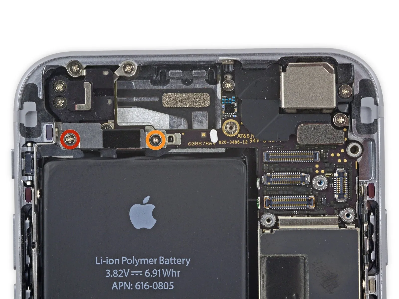
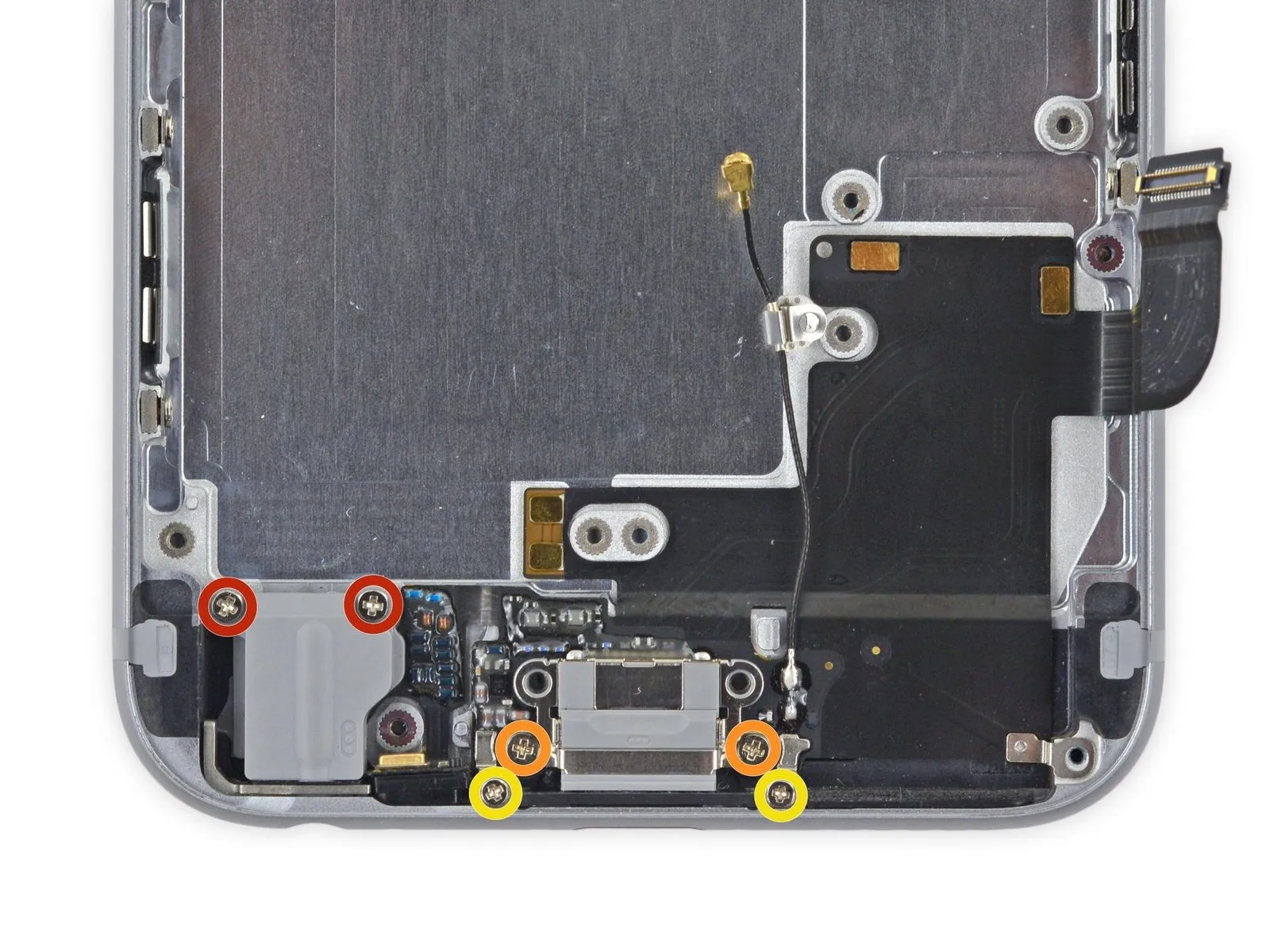
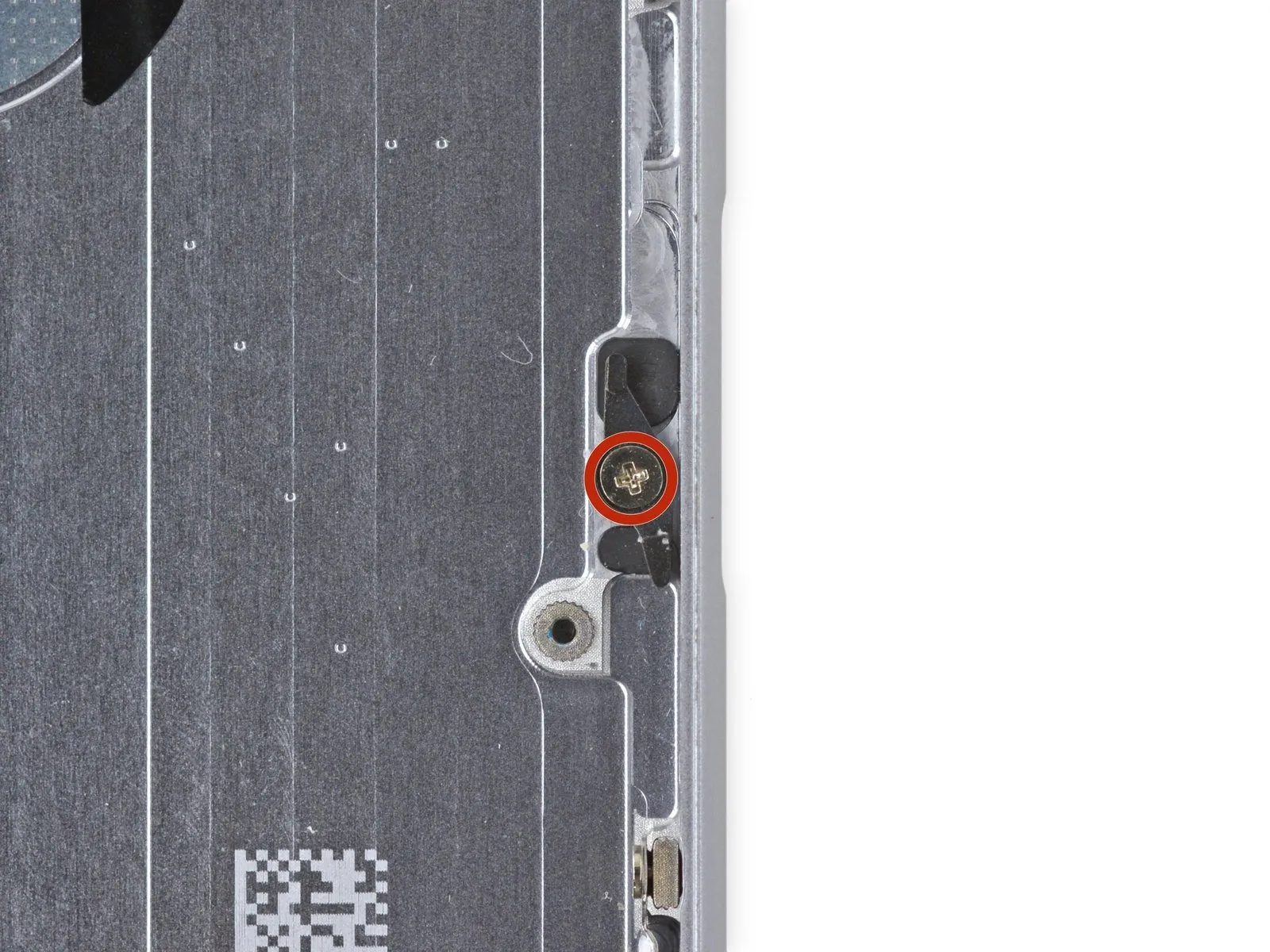
Step 1 | Pentalobe Screws

To prevent a fire hazard or explosion resulting from accidental puncture, ensure the lithium-ion battery's charge level is less than 25% prior to beginning any disassembly procedures on your iPhone.
To prevent electrical shock or damage to components, ensure the iPhone is completely de-energized prior to starting the repair process.
Using a Pentalobe screwdriver, detach the two screws measuring 3.6 millimeters in length, positioned adjacent to the Lightning connector.
To prevent electrical shock or damage to components, ensure the iPhone is completely de-energized prior to starting the repair process.
Using a Pentalobe screwdriver, detach the two screws measuring 3.6 millimeters in length, positioned adjacent to the Lightning connector.
Step 2 | Anti-Clamp instructions


To simplify the subsequent opening process, the following instructions utilize the Anti-Clamp tool, a custom design; if you do not have this tool, proceed to the steps located three sections later for an alternative approach.
Refer to the included guide for detailed procedures regarding Anti-Clamp operation.
To release the Anti-Clamp's locking arms, move the blue handle in a rearward direction.
Position the arms so they clear the left or right side of the iPhone, then gently move them into place.
Affix two suction cups, one to the front and one to the rear surface of the iPhone, close to the lower edge, situated directly above the home button.
Apply vacuum by pressing the cups firmly against the surface needing treatment.
To improve the Anti-Clamp's grip on your iPhone if the exterior feels excessively slick, apply adhesive tape to the device's surface.
Step 3


To secure the arms, advance the blue handle in its direction.
Rotate the handle fully, completing a 360-degree turn, observing for the initial expansion of the cups.
Maintain proper positioning of the suction cups; should misalignment occur, gently release the suction and readjust the arms.
Once sufficient space is created by the Anti-Clamp, slide a prying tool beneath the display.
To ensure adequate separation, reposition the handle by 90 degrees.
Allow the Anti-Clamp device to function and gradually loosen the fitting by rotating it no more than 90 degrees every few seconds.
Step 4 | Manual Opening Procedure

Lacking an Anti-Clamp tool, secure the front panel with a single suction cup for lifting.
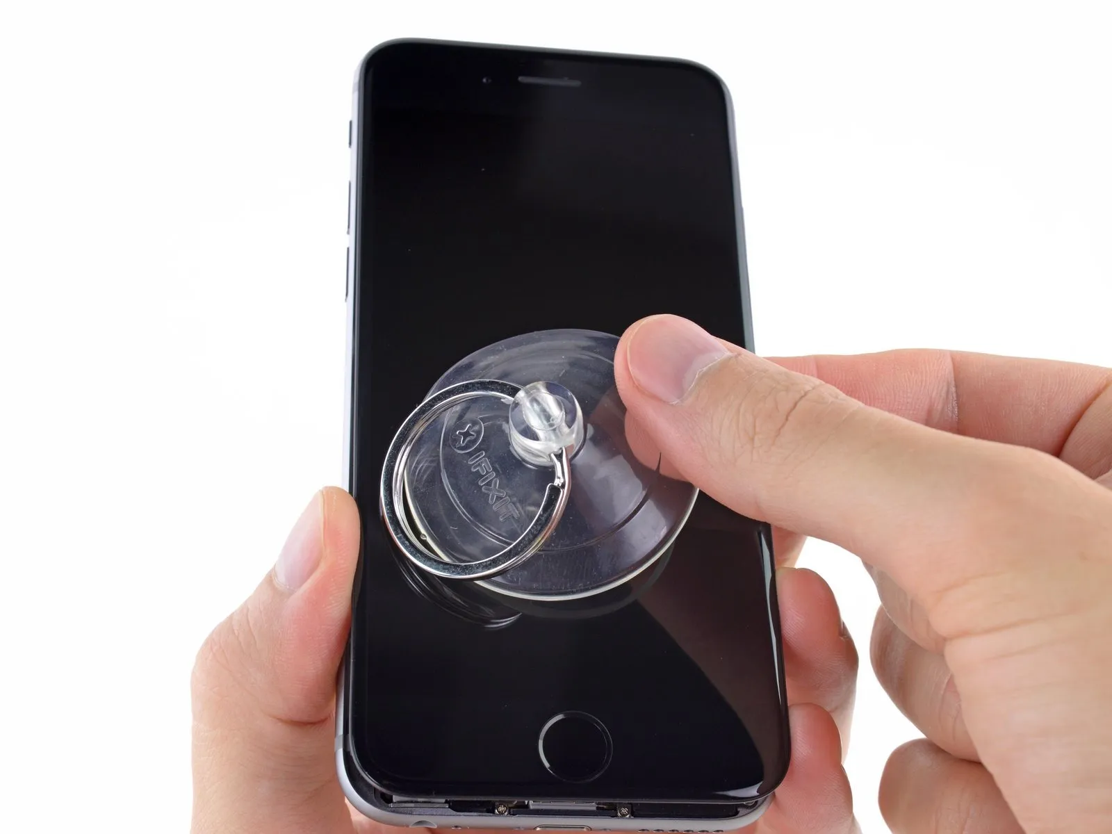
Position a suction cup directly on the display surface, situated slightly higher than the home button's location.
Ensure a firm contact between the cup and the screen surface to guarantee a leakproof connection.
To facilitate suction cup attachment when a display exhibits severe cracking, apply a sheet of clear packing tape across the damaged area; as an alternative, a robust adhesive tape can be substituted for the suction cup. Should these methods prove ineffective, secure the suction cup directly to the fractured screen using superglue.
Step 5
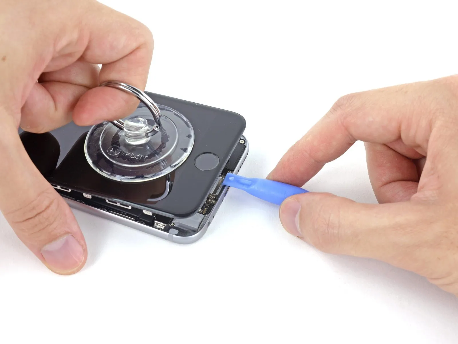
Using one hand to secure the iPhone, lift the suction cup vertically to create a small gap between the front panel and the rear enclosure.
Exercise patience and use steady, even pressure when installing the display assembly, as it requires a significantly tighter fit than typical device components.
Carefully separate the rear case from the display assembly by gently levering it downward with a plastic opening tool, maintaining upward traction on the display with a suction cup.
To release the front panel assembly from the rear case, carefully disengage the multiple retaining clips, potentially requiring the coordinated use of both the suction cup and the plastic opening tool.
Step 6

To detach the suction cup, depress the plastic projection to break the airtight seal.
Detach the display assembly's suction cup.
Detach the display assembly's suction cup.
Step 7 | Opening up the phone

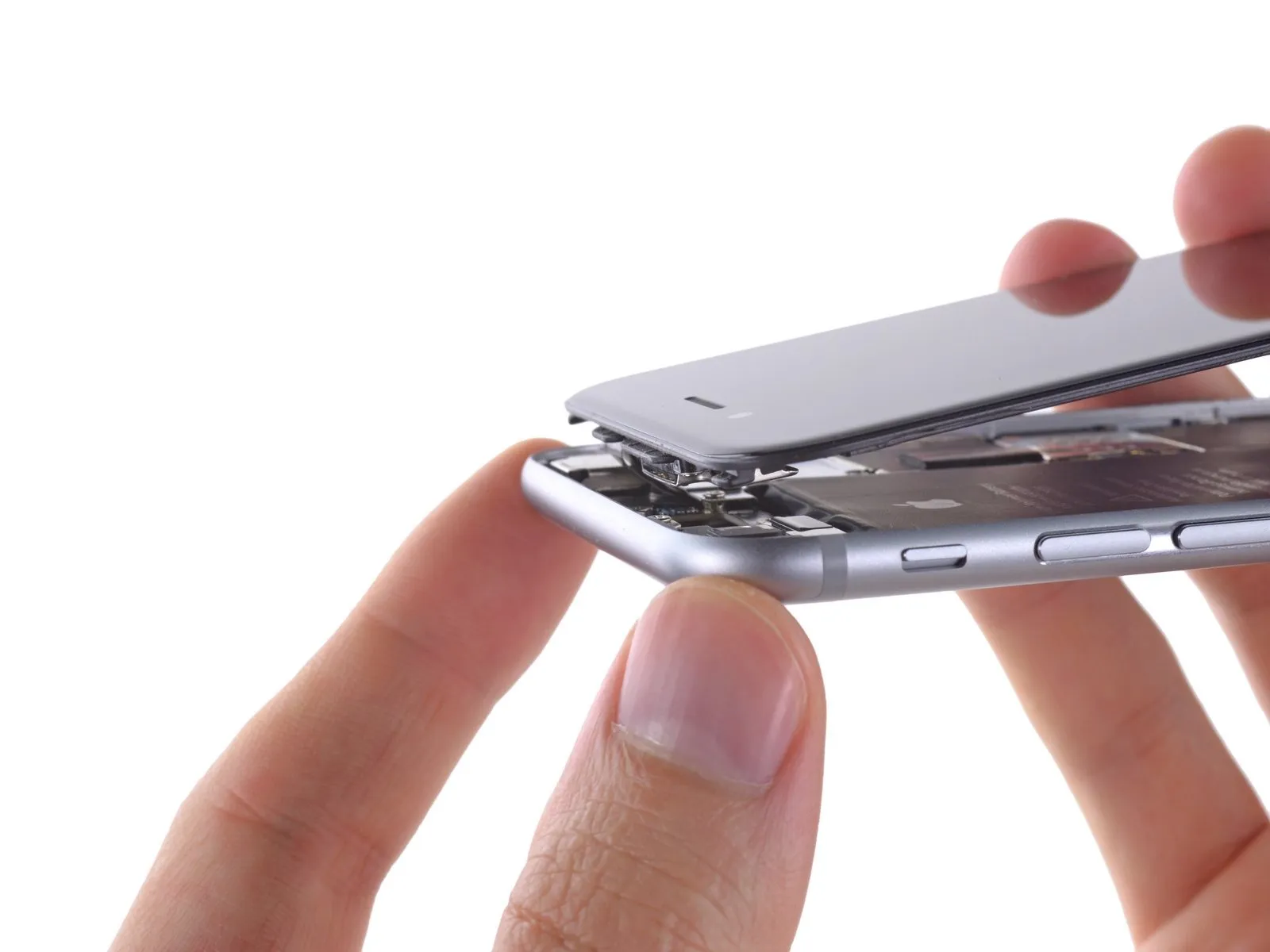
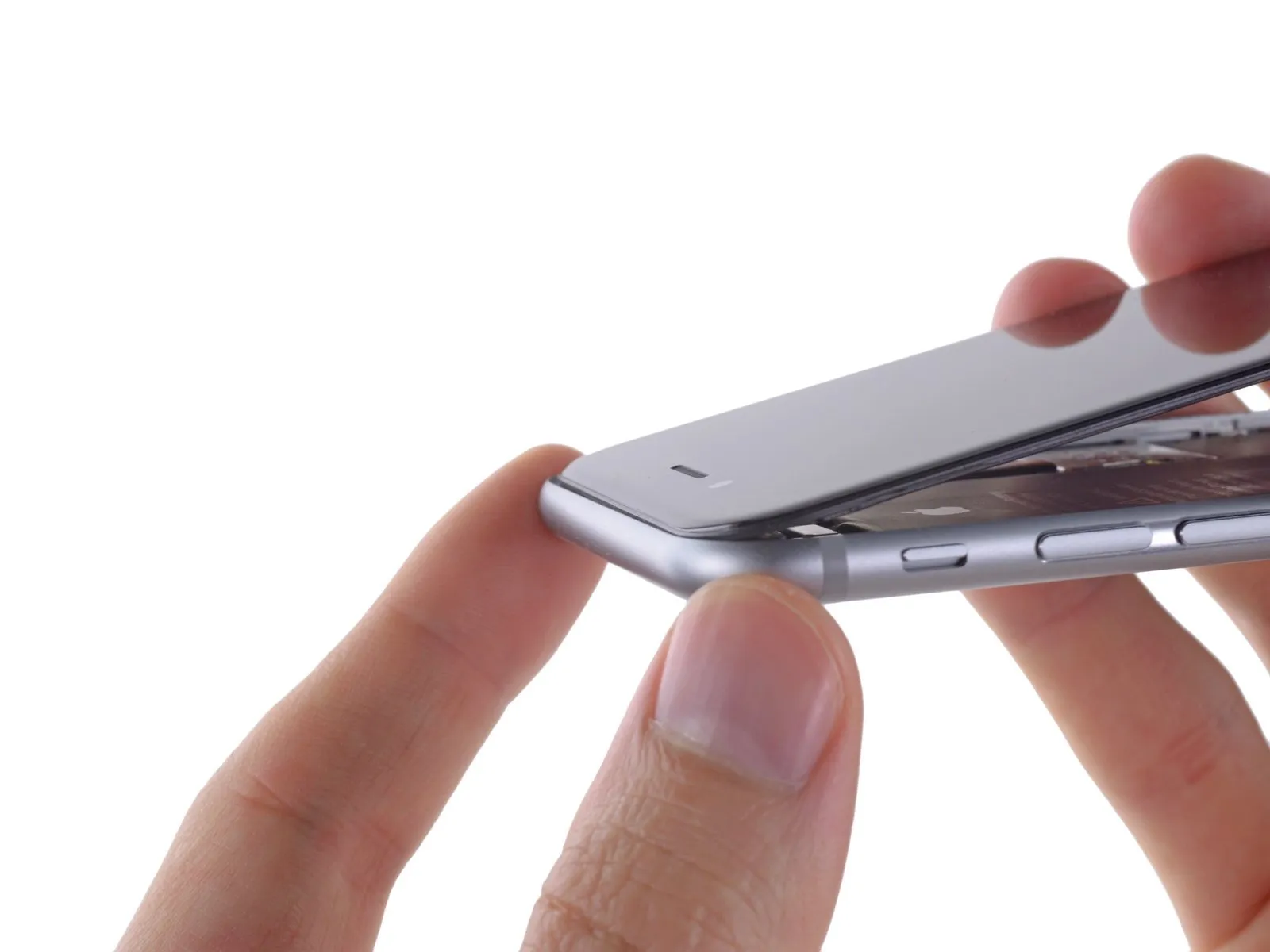
Employing the phone's upper edge as a pivot point, carefully detach the front panel assembly from the rear case by moving the home button end outward.
The front panel’s upper edge incorporates multiple clips that function as a partial hinge.
Ensure the clips, positioned directly beneath the rear case's upper border, are properly aligned before sliding the front panel upwards; the front panel's top edge should then be level with the rear case's top edge.
Step 8

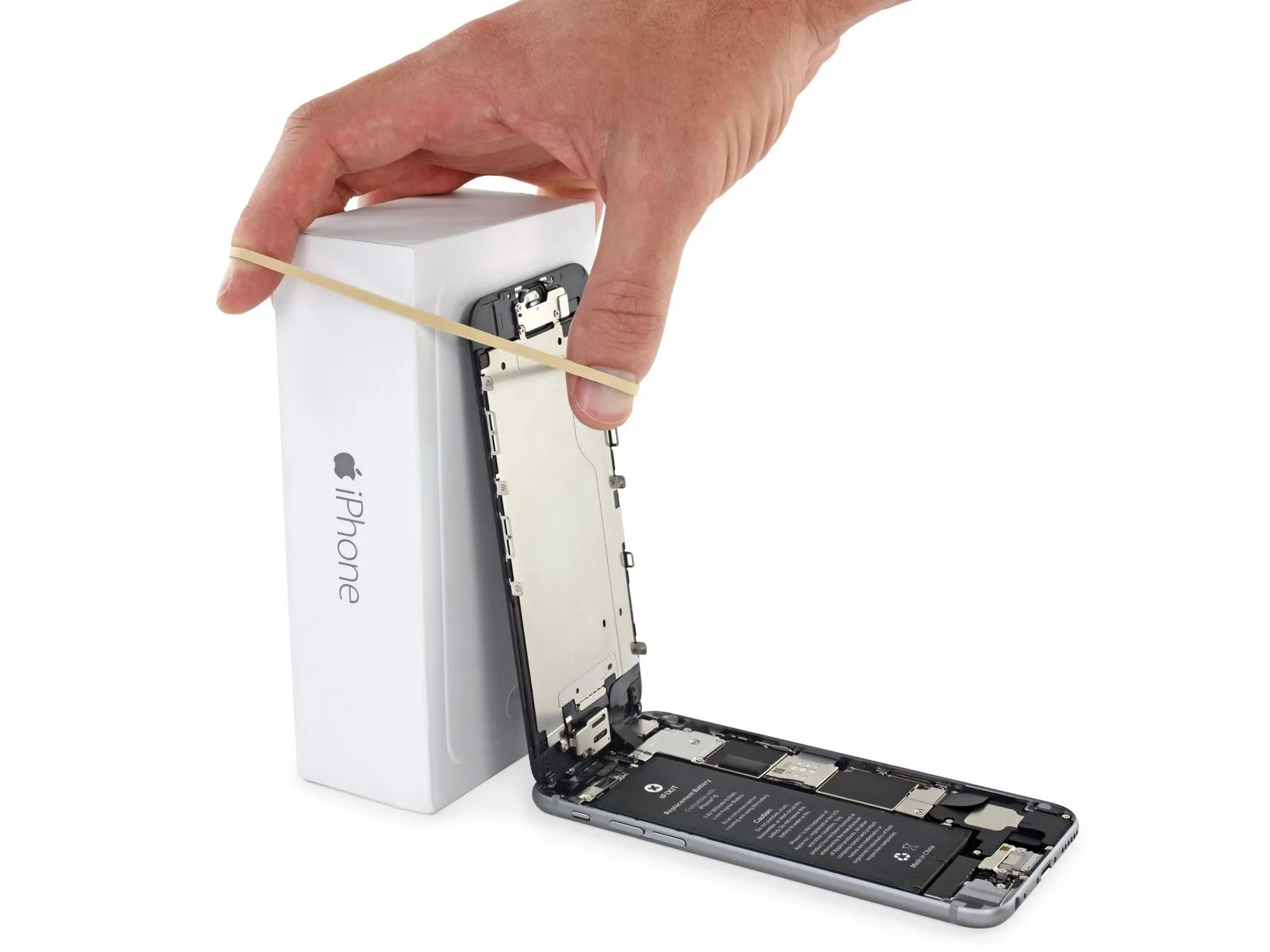
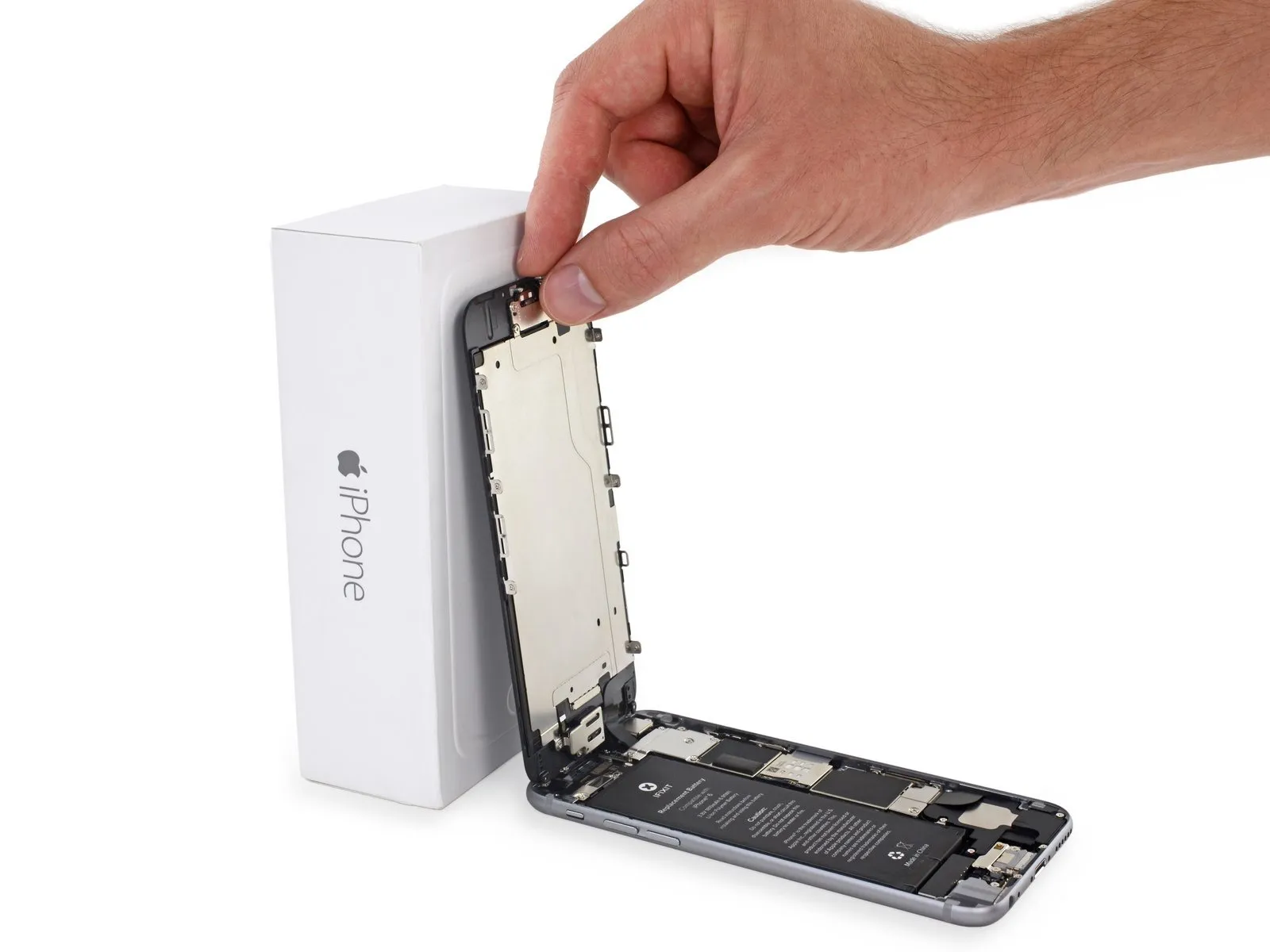
Carefully position the display at a 90-degree angle and secure it in an upright position using a support to prevent movement during the repair process.
If a dedicated calibration tool is unavailable, a factory-sealed, unopened can of carbonated drink can be substituted, ensuring it maintains its original volume and pressure.
To avoid stressing the display's wiring during the repair process, secure it with a rubber band.
If a dedicated calibration tool is unavailable, a factory-sealed, unopened can of carbonated drink can be substituted, ensuring it maintains its original volume and pressure.
To avoid stressing the display's wiring during the repair process, secure it with a rubber band.
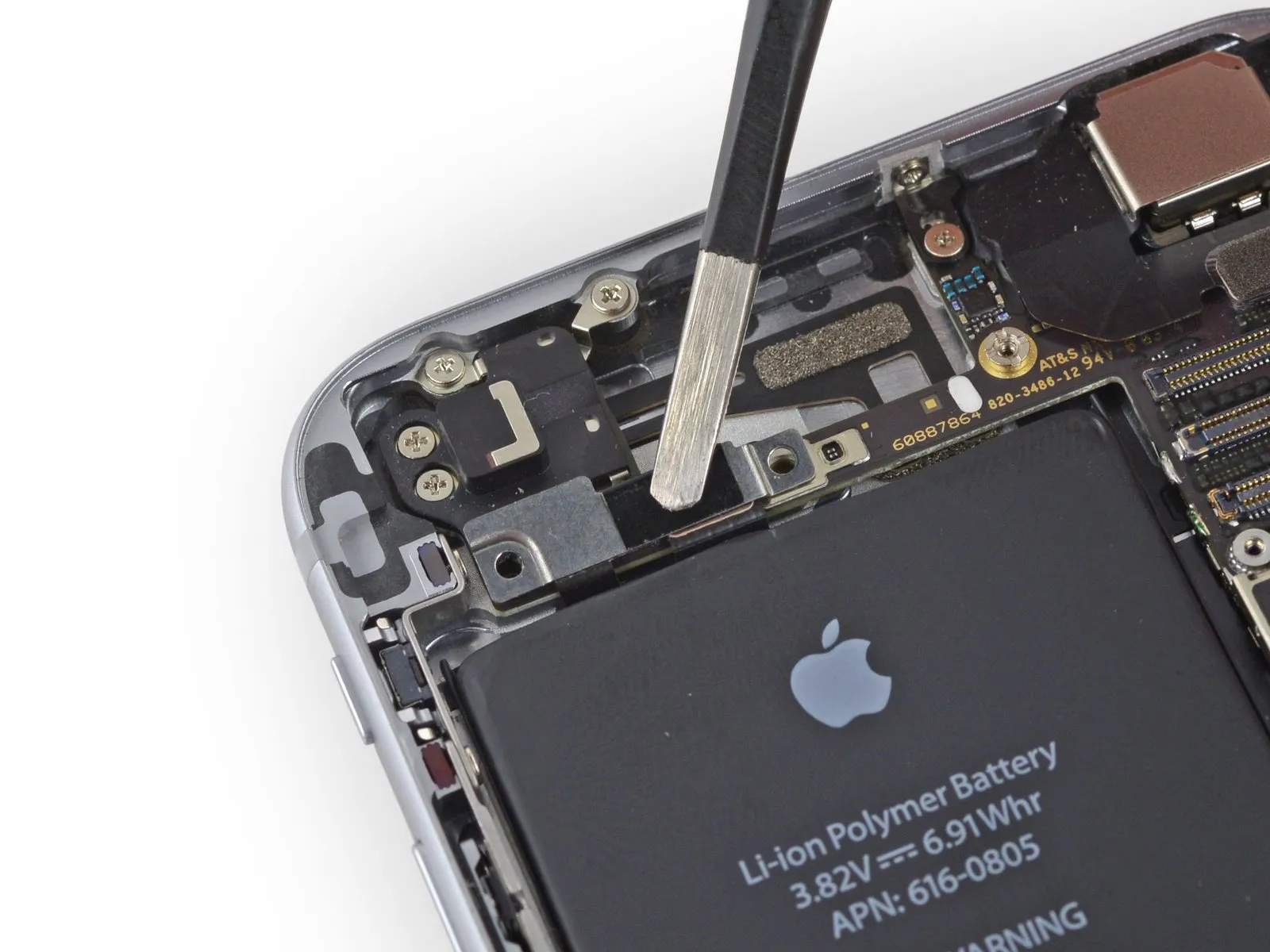
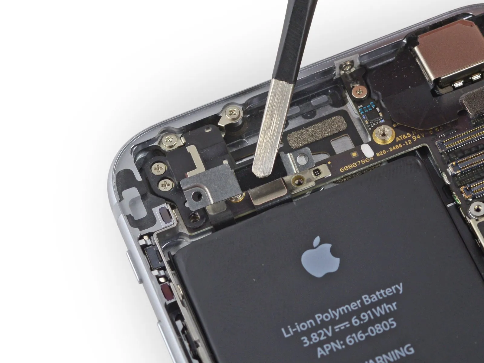
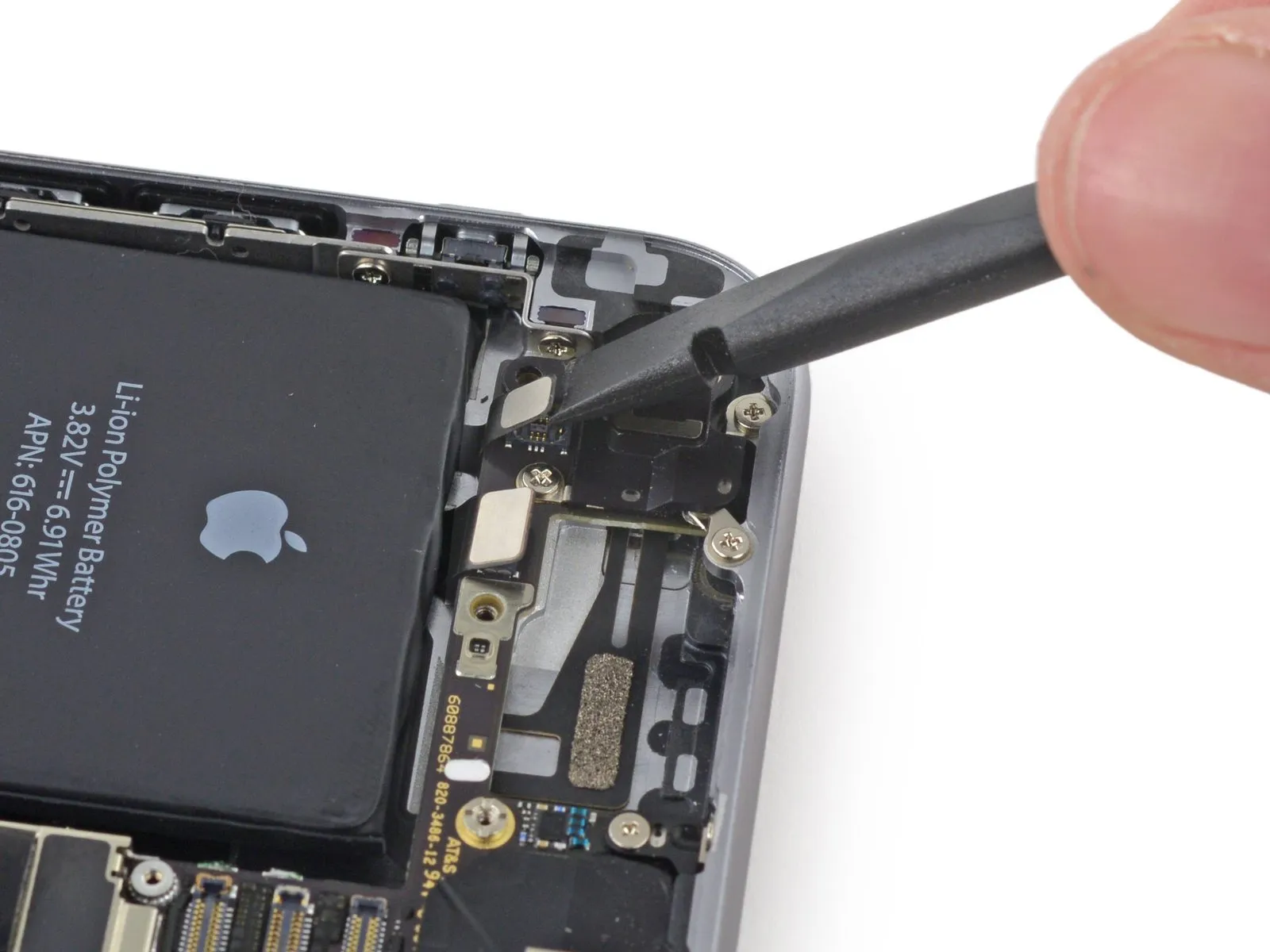
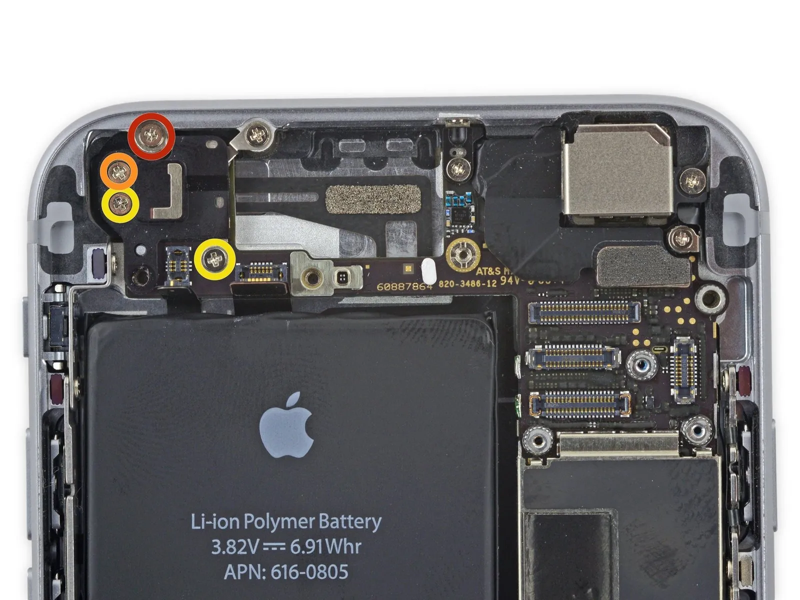
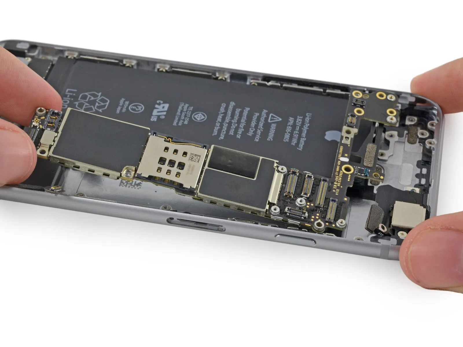
Step 9 | Removing the battery connector bracket screws
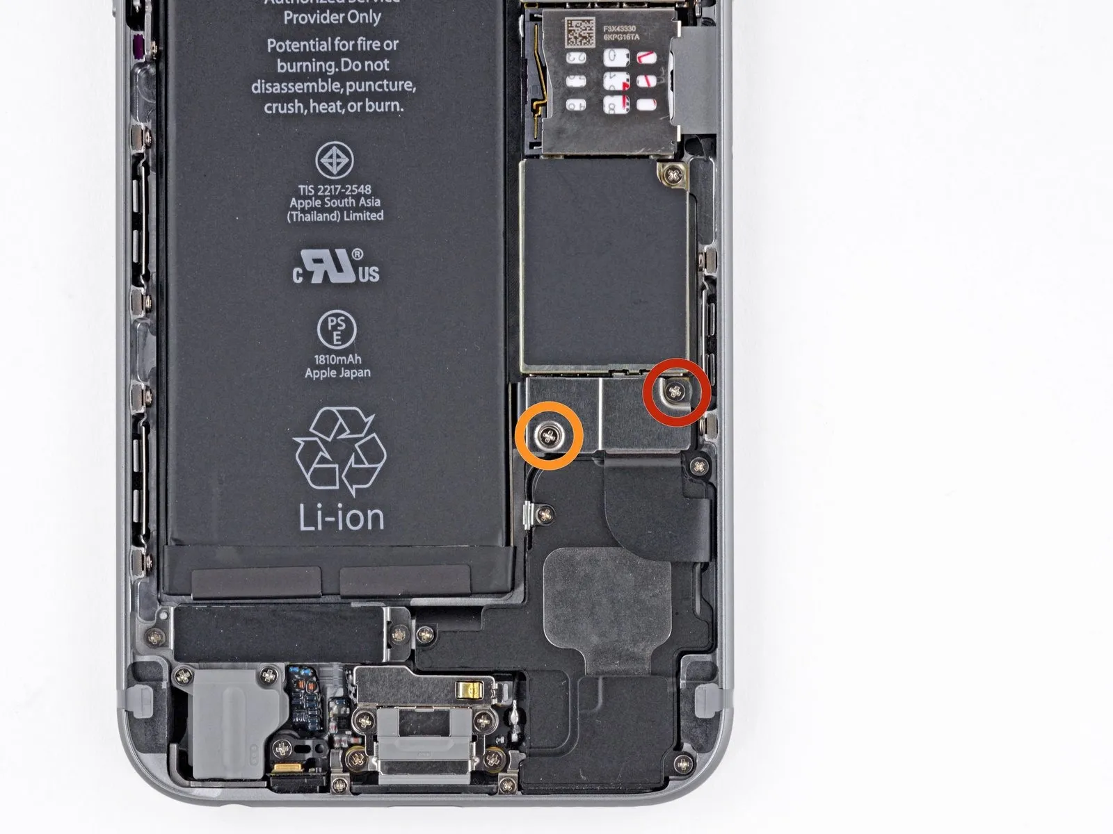
Using a Phillips screwdriver, detach the bracket securing the battery connector by unscrewing the included fasteners.
A single screw, measuring 2.2 millimeters, is required.
A single screw, measuring 3.2 millimeters, is required.
Carefully note the location of every screw during disassembly, as reassembly requires placing each one in its original position to prevent potential damage to the device.
A single screw, measuring 2.2 millimeters, is required.
A single screw, measuring 3.2 millimeters, is required.
Carefully note the location of every screw during disassembly, as reassembly requires placing each one in its original position to prevent potential damage to the device.
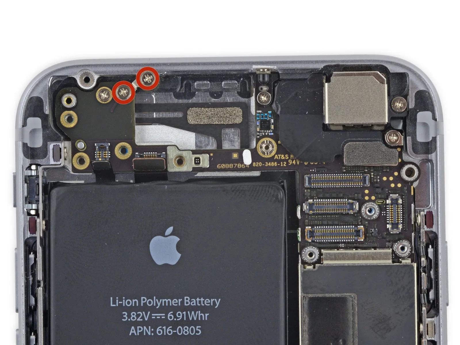
Step 10
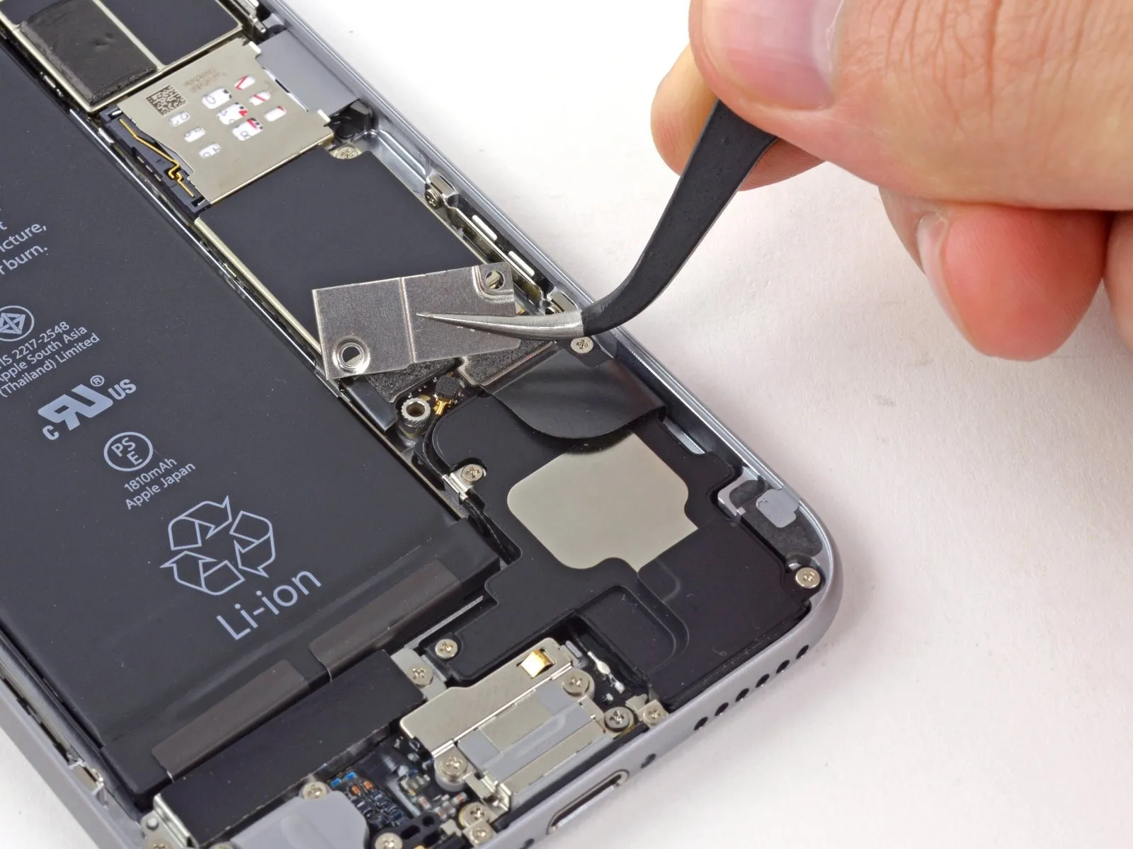
Detach the bracket securing the battery connector using a Tri-Point Y000 screwdriver.
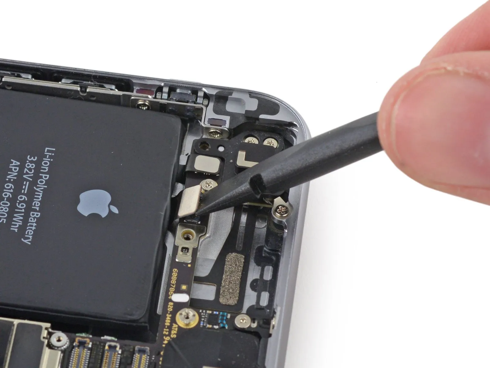
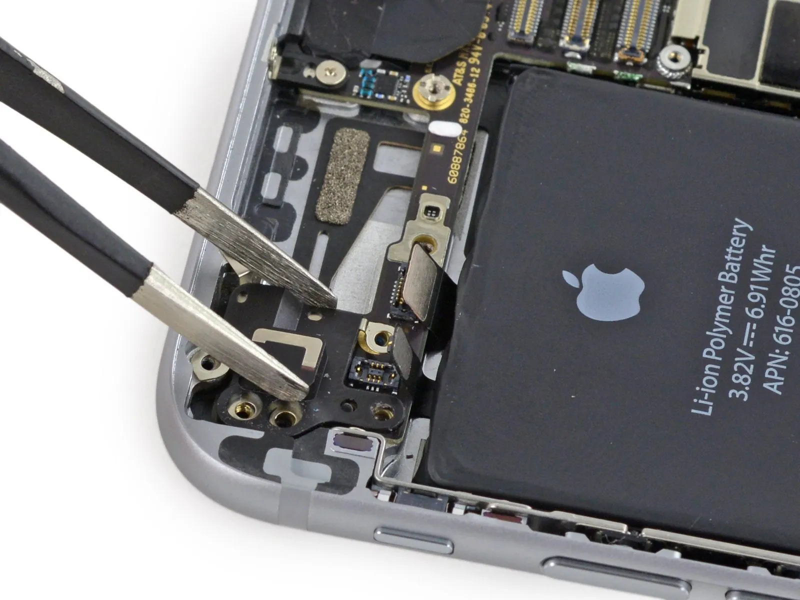
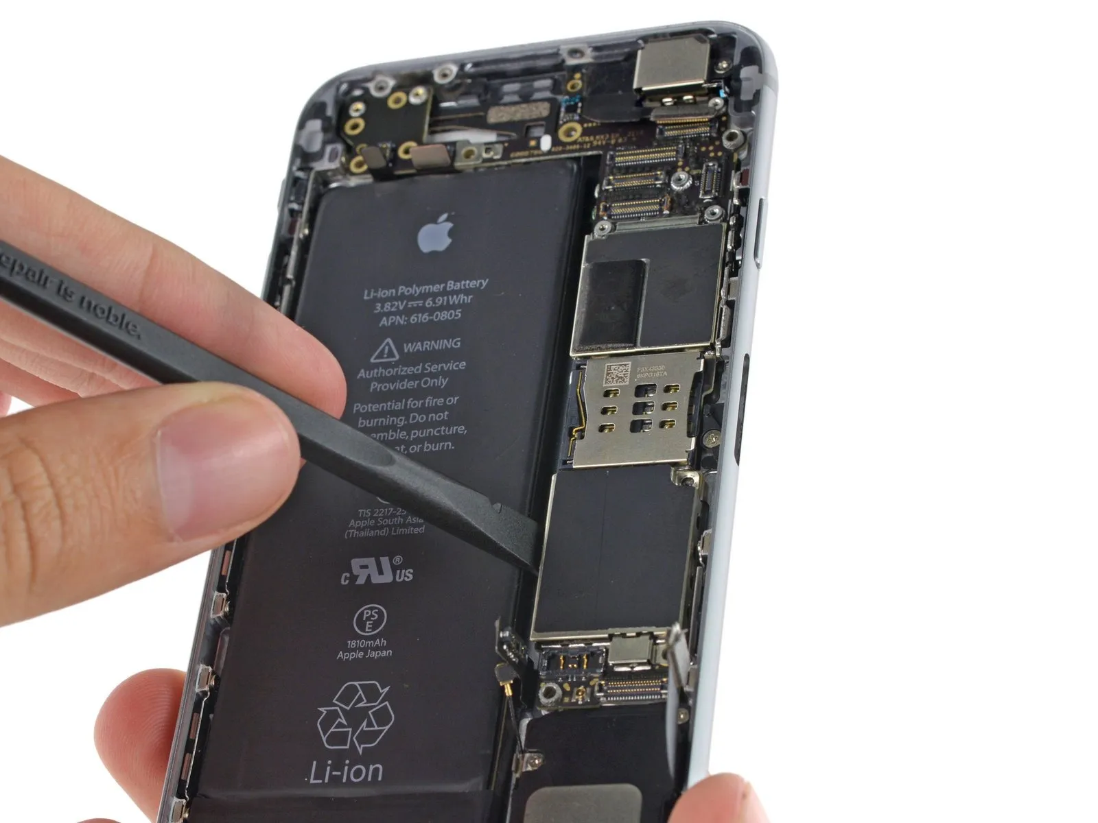
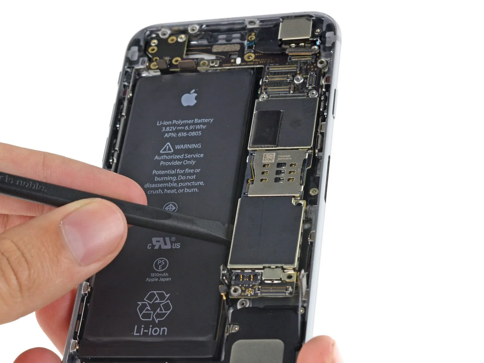
Step 11 | Disconnecting the battery connector
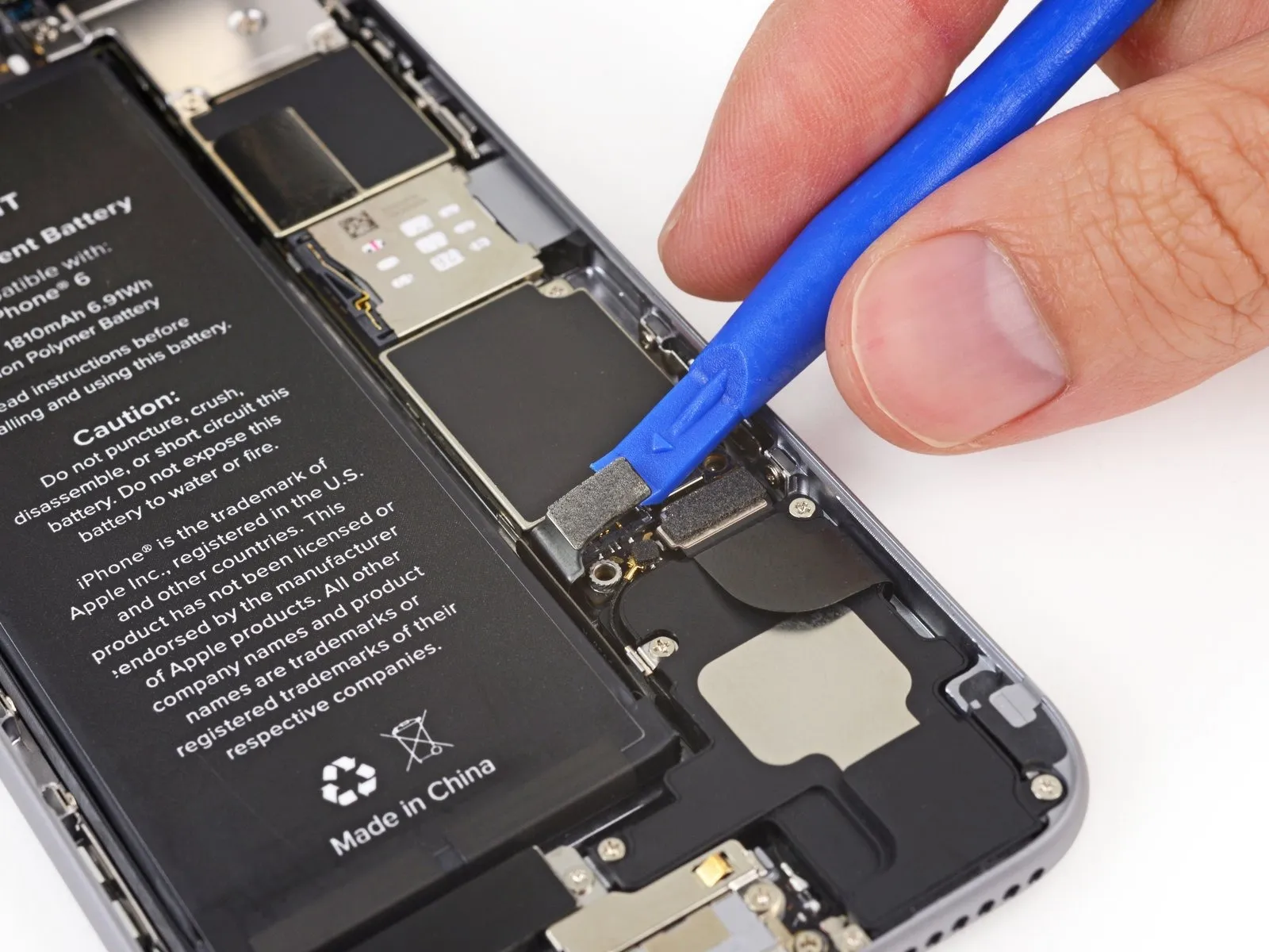
Carefully lift the battery connector away from its corresponding socket on the logic board, utilizing a plastic opening tool to avoid damage.
To prevent damage, lift solely on the battery connector itself; applying force to the logic board socket risks complete connector failure.
To prevent damage, lift solely on the battery connector itself; applying force to the logic board socket risks complete connector failure.
Step 12 | Removing the front panel assembly cable bracket screws
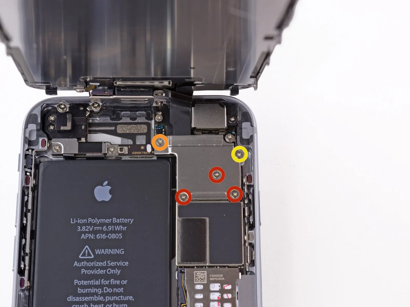
Using a Phillips screwdriver, detach the cable bracket from the front panel assembly by unscrewing the five screws it holds in place.
Use three screws, each measuring 1.2 millimeters.
A single screw, measuring 1.7 millimeters, is required.
A single screw, measuring 3.1 millimeters, is required.
Improper screw installation during reassembly can result in irreversible harm to the iPhone's logic board.
Use three screws, each measuring 1.2 millimeters.
A single screw, measuring 1.7 millimeters, is required.
A single screw, measuring 3.1 millimeters, is required.
Improper screw installation during reassembly can result in irreversible harm to the iPhone's logic board.
Step 13
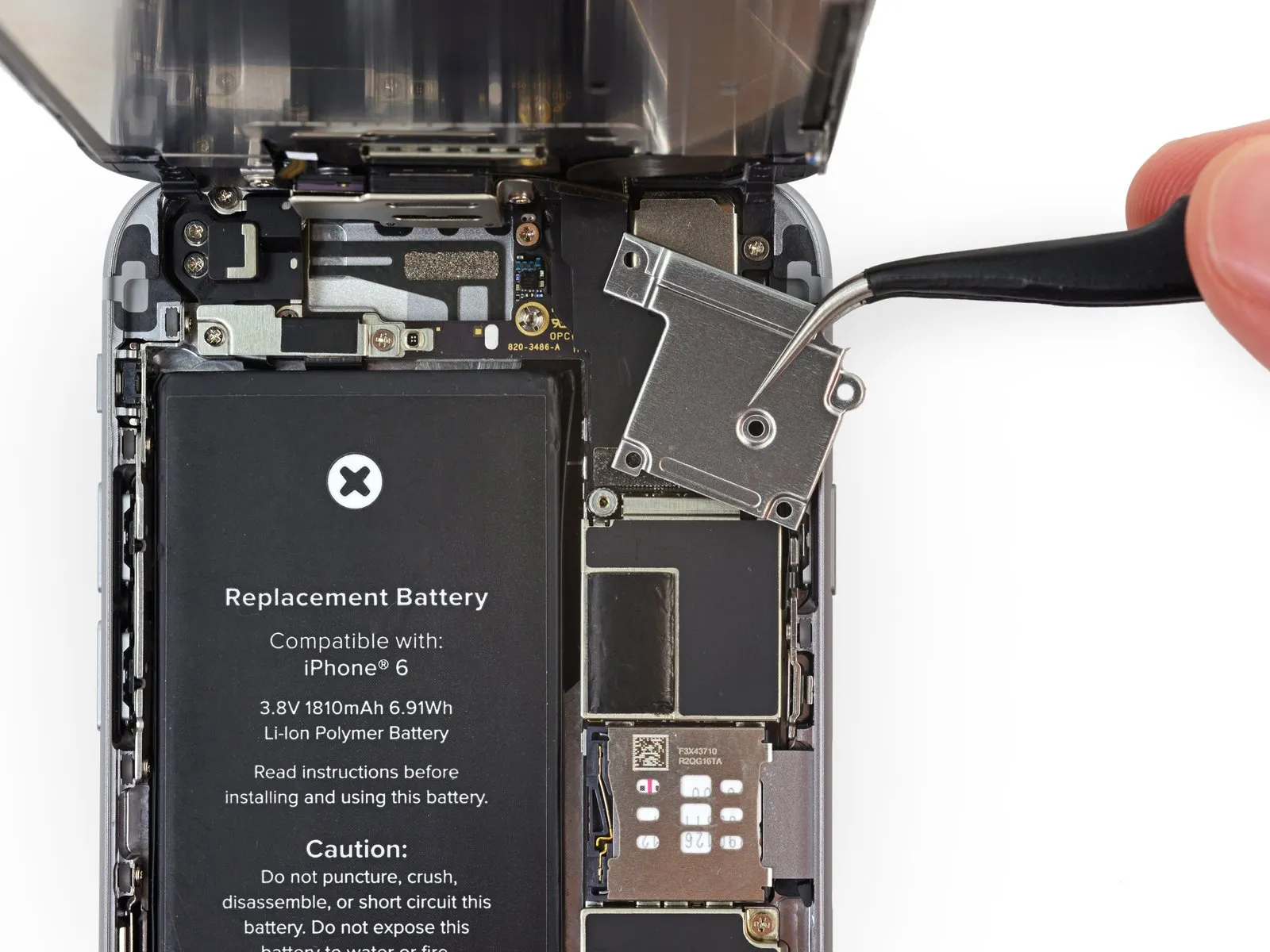
Detach the cable bracket securing the front panel assembly cable to the logic board.
Step 14
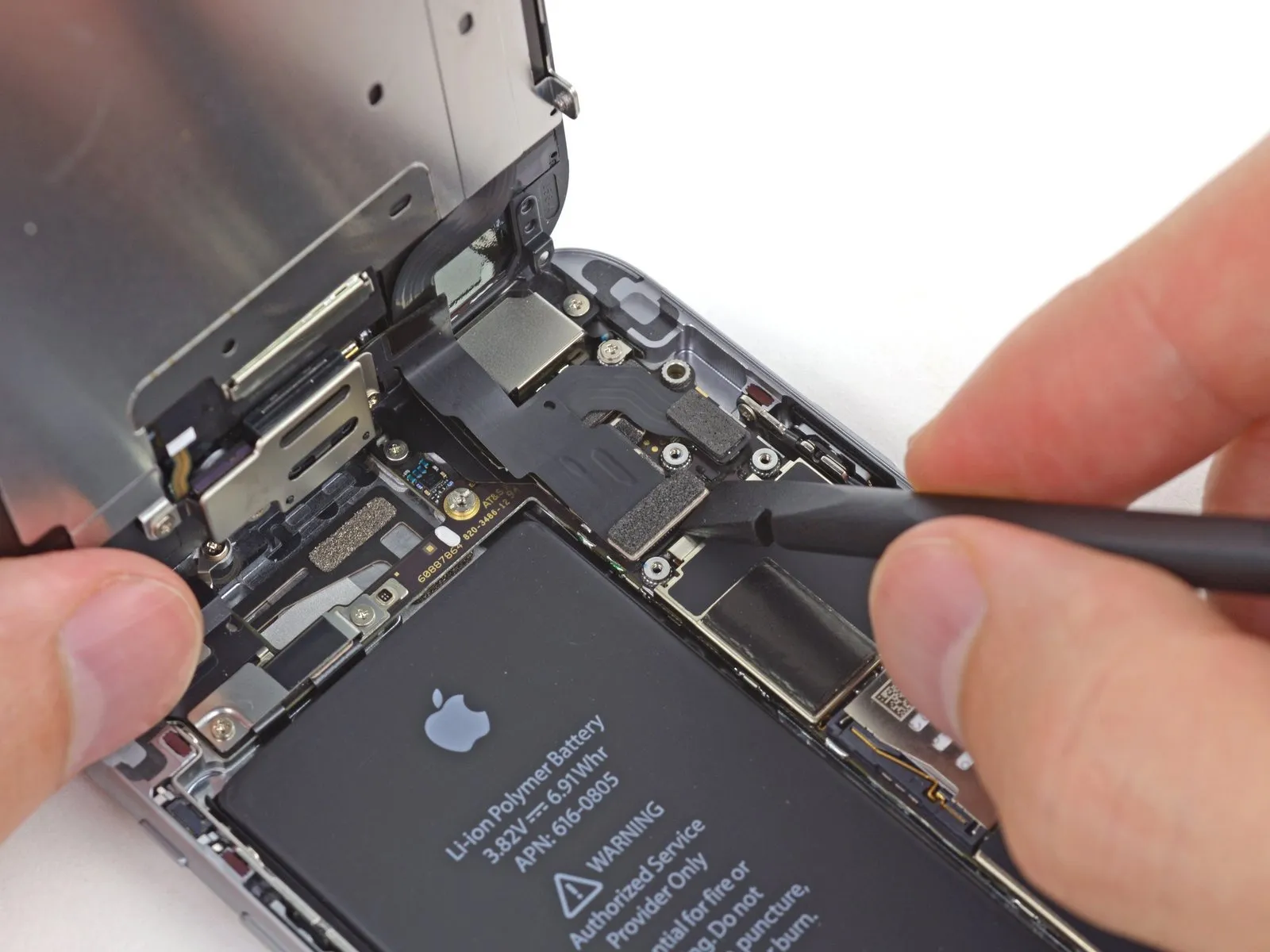

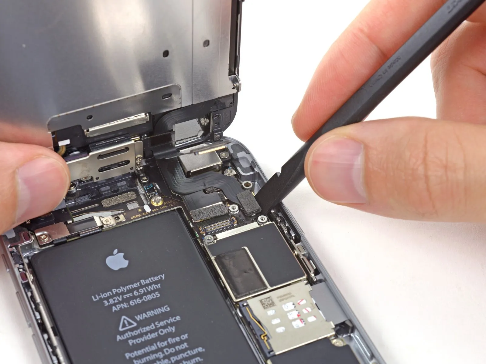
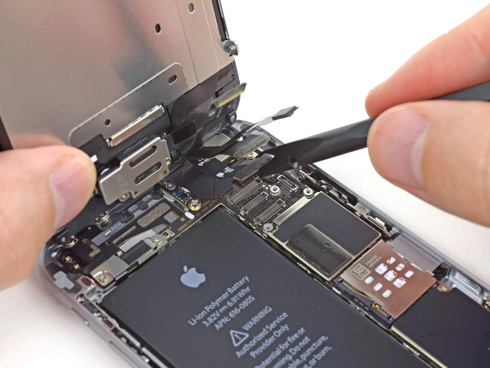
When proceeding with the subsequent four steps, ensure that you apply lifting force solely to the cable connectors themselves, avoiding any pressure on the sockets they connect to on the logic board.
Carefully detach the front camera and sensor cable connector from its socket using a spudger or similar tool.
Carefully detach the front camera and sensor cable connector from its socket using a spudger or similar tool.
Step 15
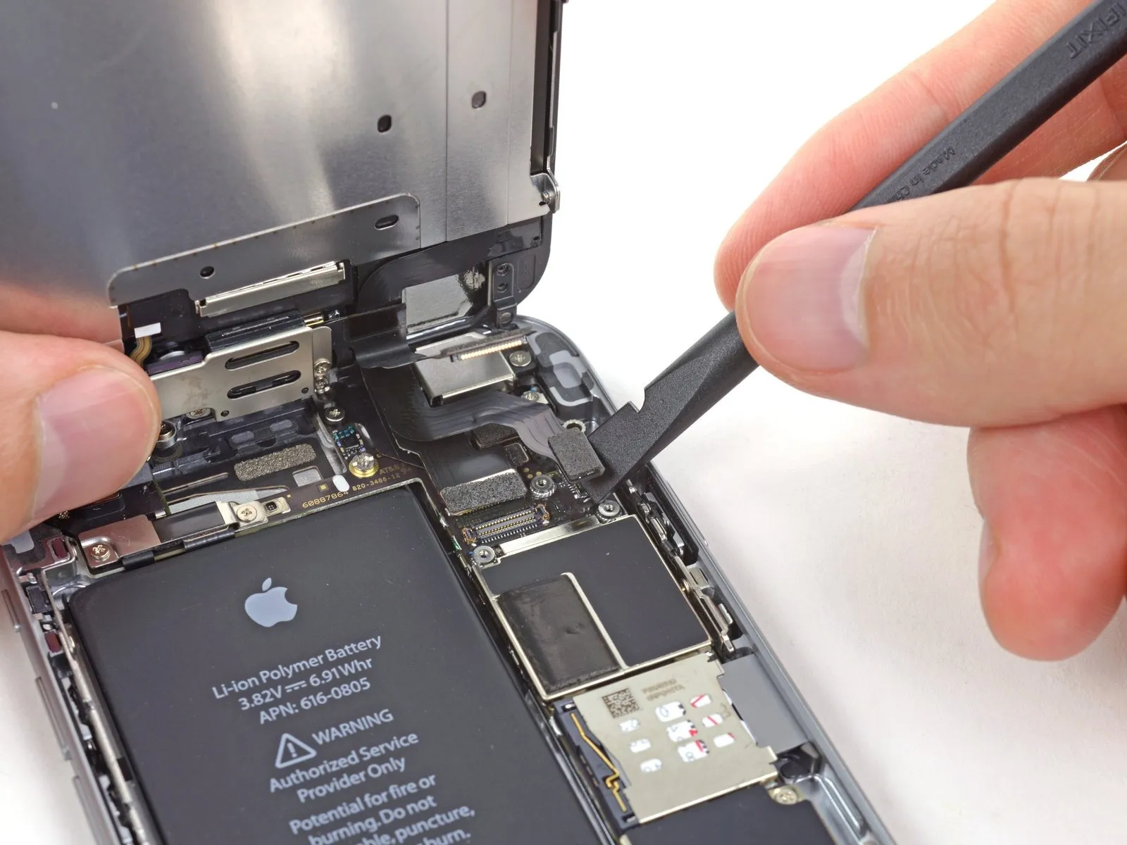
Carefully detach the home button cable connector using a spudger or fingernail.
Step 16
Using a 5/32-inch hex key, carefully tighten the four M4x8 pan head screws securing the fan assembly to the heatsink, ensuring a torque of 4.5 in-lbs to prevent damage.
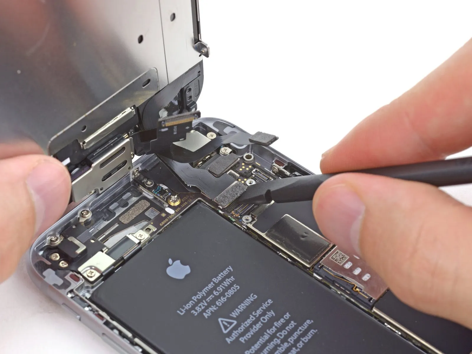
Prior to either detaching or reattaching the cable in this procedure, ensure the battery is disconnected.
Prior to either detaching or reattaching the cable in this procedure, ensure the battery is disconnected.
- Carefully detach the display data cable connector from its socket using a spudger or similar tool.
- Should the display data cable become detached from its connector during reassembly, a blank screen or white lines might appear upon powering on the device; to resolve this, reattach the cable and restart the phone, preferably by disconnecting and reconnecting the battery connector.
Step 17

Carefully align the 4mm diameter dowel pins, ensuring they are fully seated within the corresponding holes on both the upper and lower chassis sections before securing with the provided M3 x 6mm screws using a Phillips head screwdriver, observing caution to avoid over-tightening.
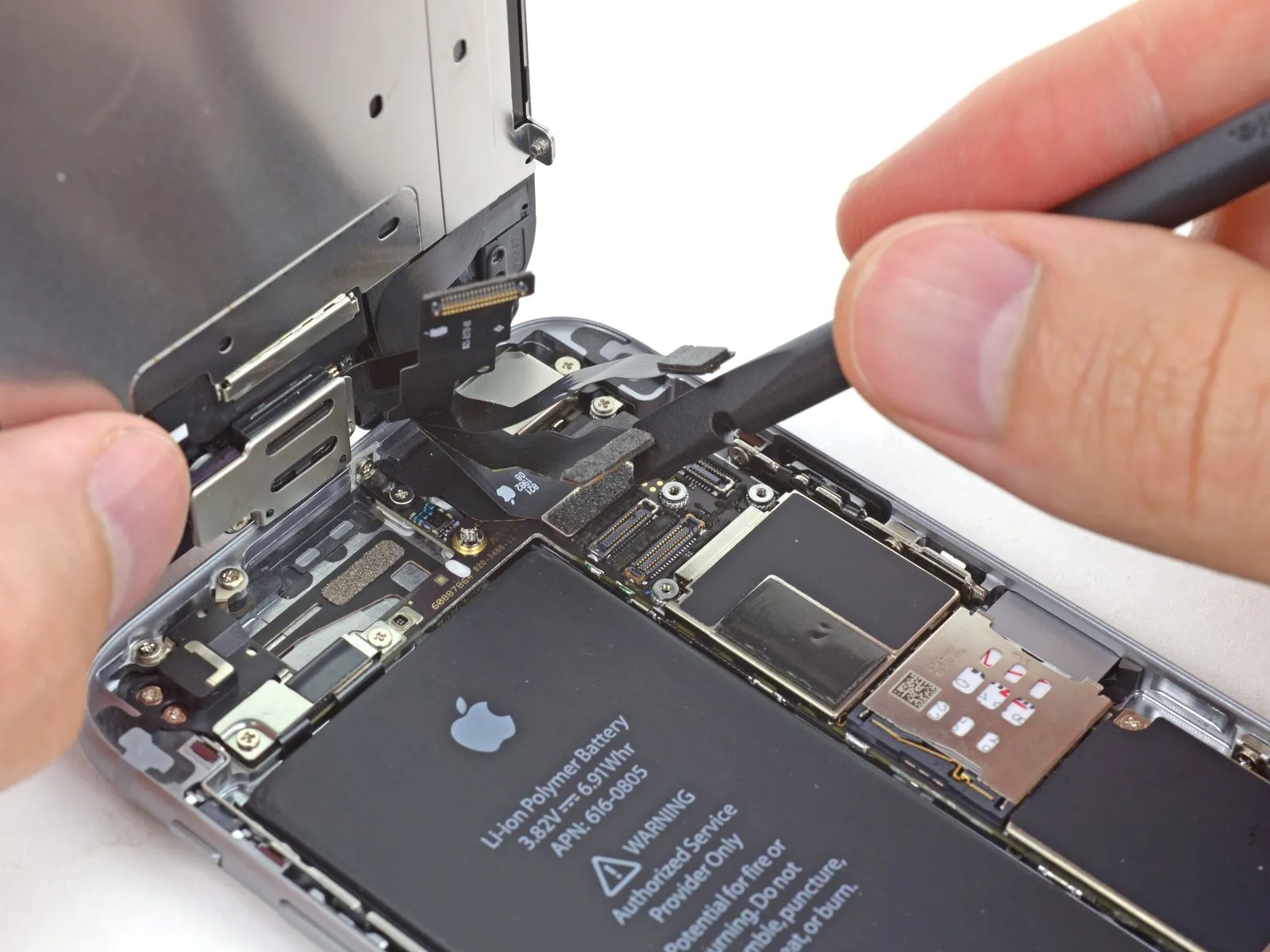
Carefully separate the digitizer cable connector from its socket using the flat tool end of a spudger.
Carefully separate the digitizer cable connector from its socket using the flat tool end of a spudger.
- To avoid damaging the digitizer, ensure the connector is secured by applying pressure to its opposing ends, rather than the central portion; central pressure may deform the component.
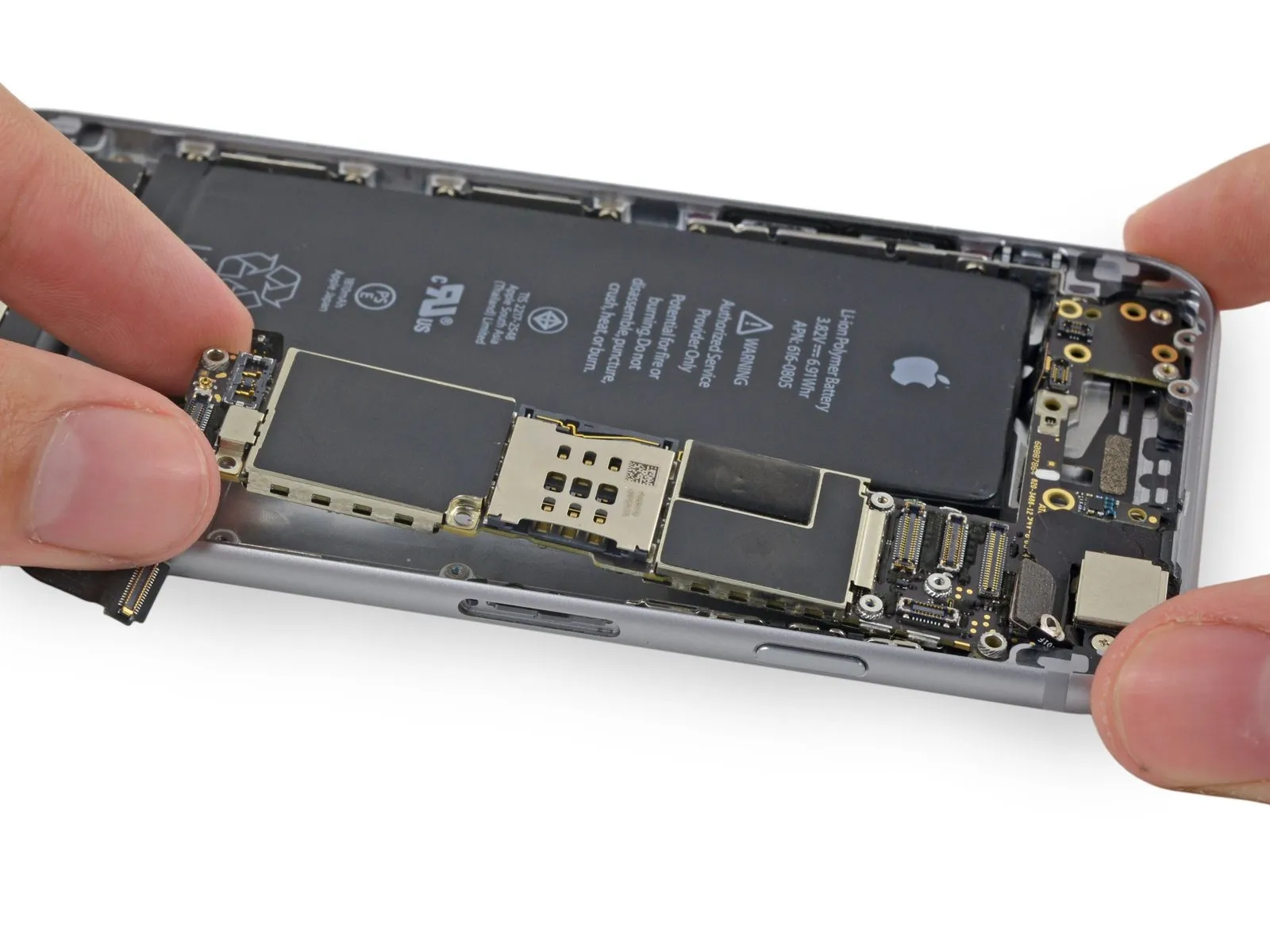
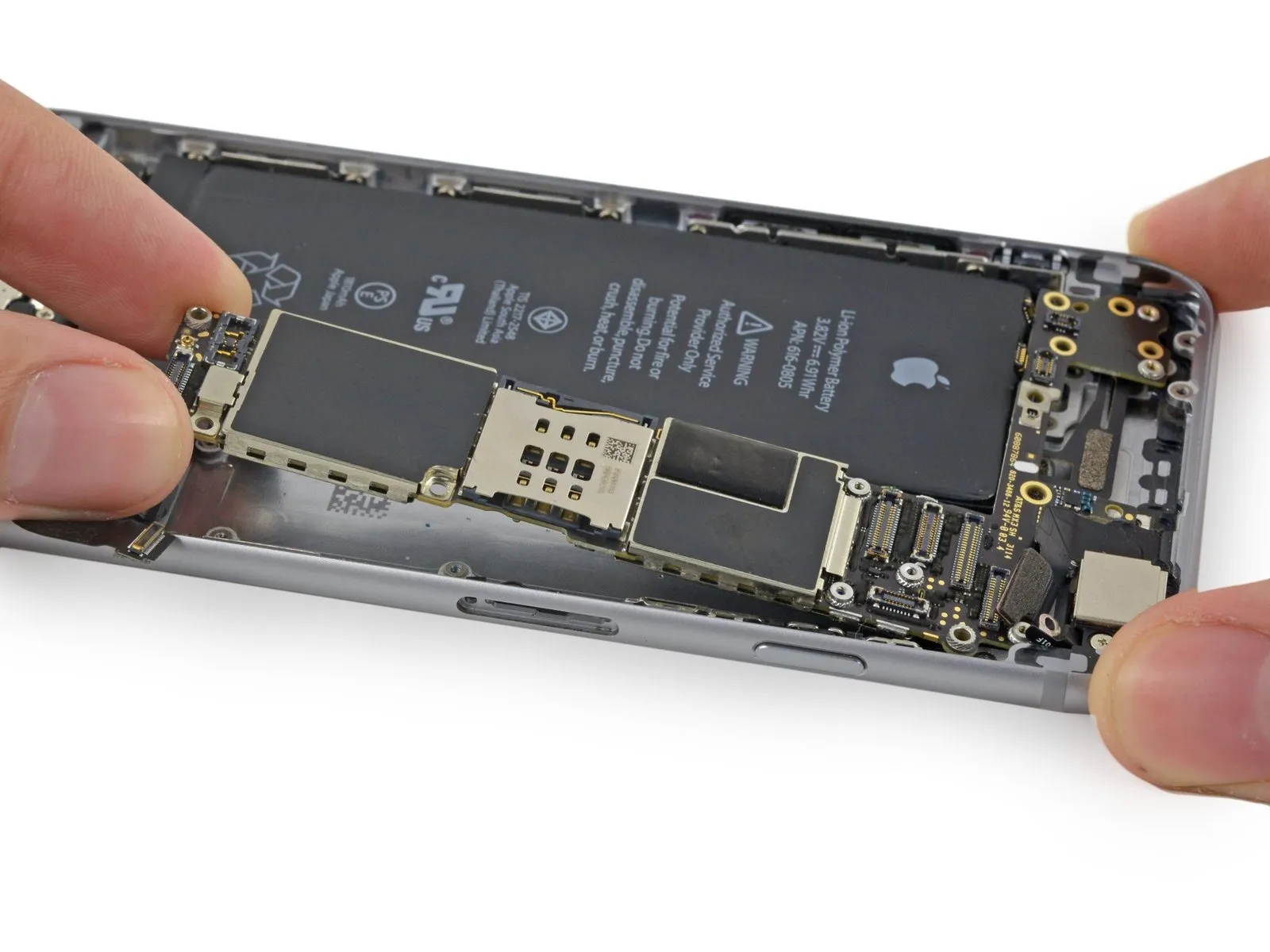
Step 18 | Separating front panel assembly and rear case

Using a 5/32-inch hex key, carefully tighten the four M4x8 pan head screws securing the fan assembly to the heatsink, ensuring a torque of 4.5 in-lbs to prevent damage.
Detach the front panel assembly from the rear case.
Detach the front panel assembly from the rear case.
Step 19 | SIM Card


Carefully align the 4mm hex key to the setscrew, ensuring the screwdriver bit is fully seated, and then tighten the setscrew to a torque of 1.5 Nm using the hex key.
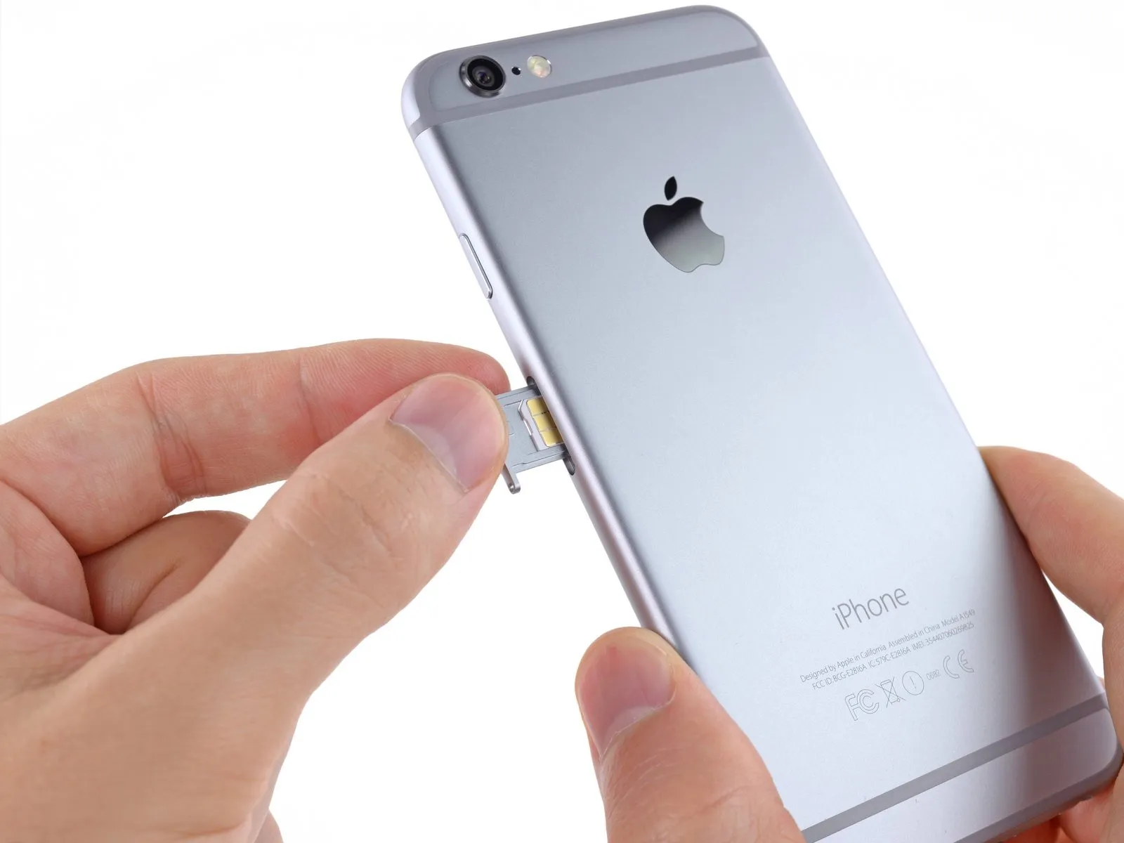
Using a SIM card eject tool or a straightened paperclip, gently push into the tiny aperture located on the SIM card tray to release it.
Apply force to release the tray from its housing.
Applying considerable pressure might be necessary.
Using a SIM card eject tool or a straightened paperclip, gently push into the tiny aperture located on the SIM card tray to release it.
Apply force to release the tray from its housing.
Applying considerable pressure might be necessary.
Step 20
Using a 5/32-inch hex key, carefully tighten the four M4x8 screws securing the fan assembly to the heatsink, ensuring a torque of 4.5 in-lbs is achieved to prevent damage.
Using a SIM ejection tool or a straightened paperclip, carefully release and extract the SIM card tray assembly from the iPhone.
Confirm the SIM card's correct alignment within the tray before sliding the tray back into the device.
Using a SIM ejection tool or a straightened paperclip, carefully release and extract the SIM card tray assembly from the iPhone.
Confirm the SIM card's correct alignment within the tray before sliding the tray back into the device.
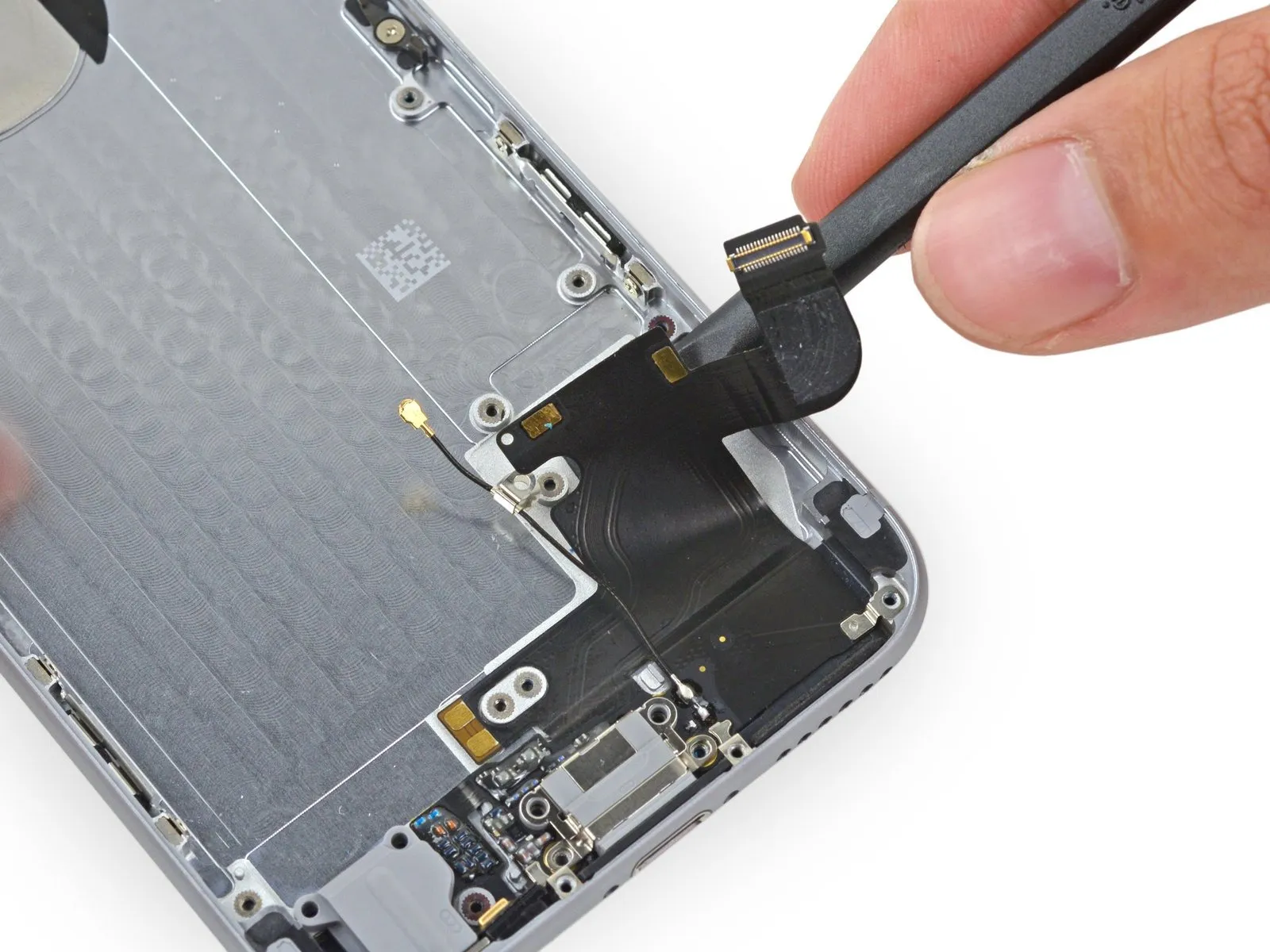
Step 21 | Logic Board

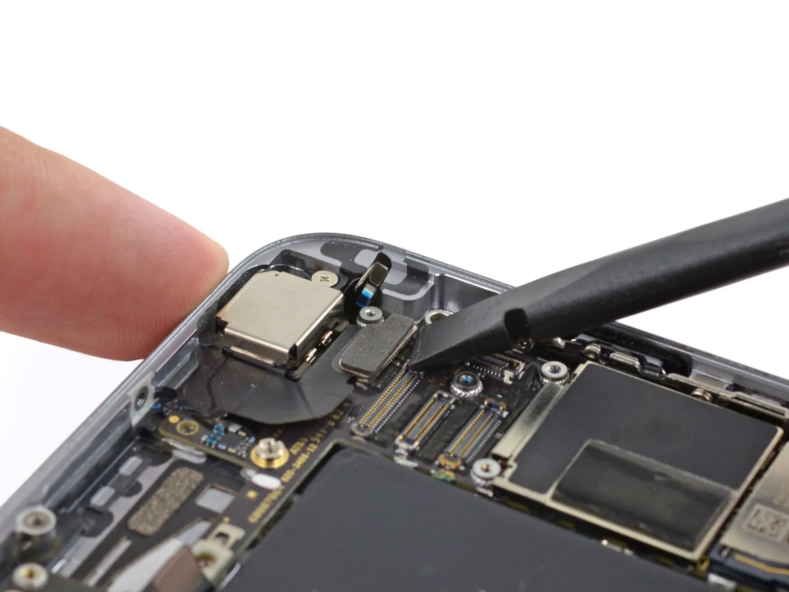
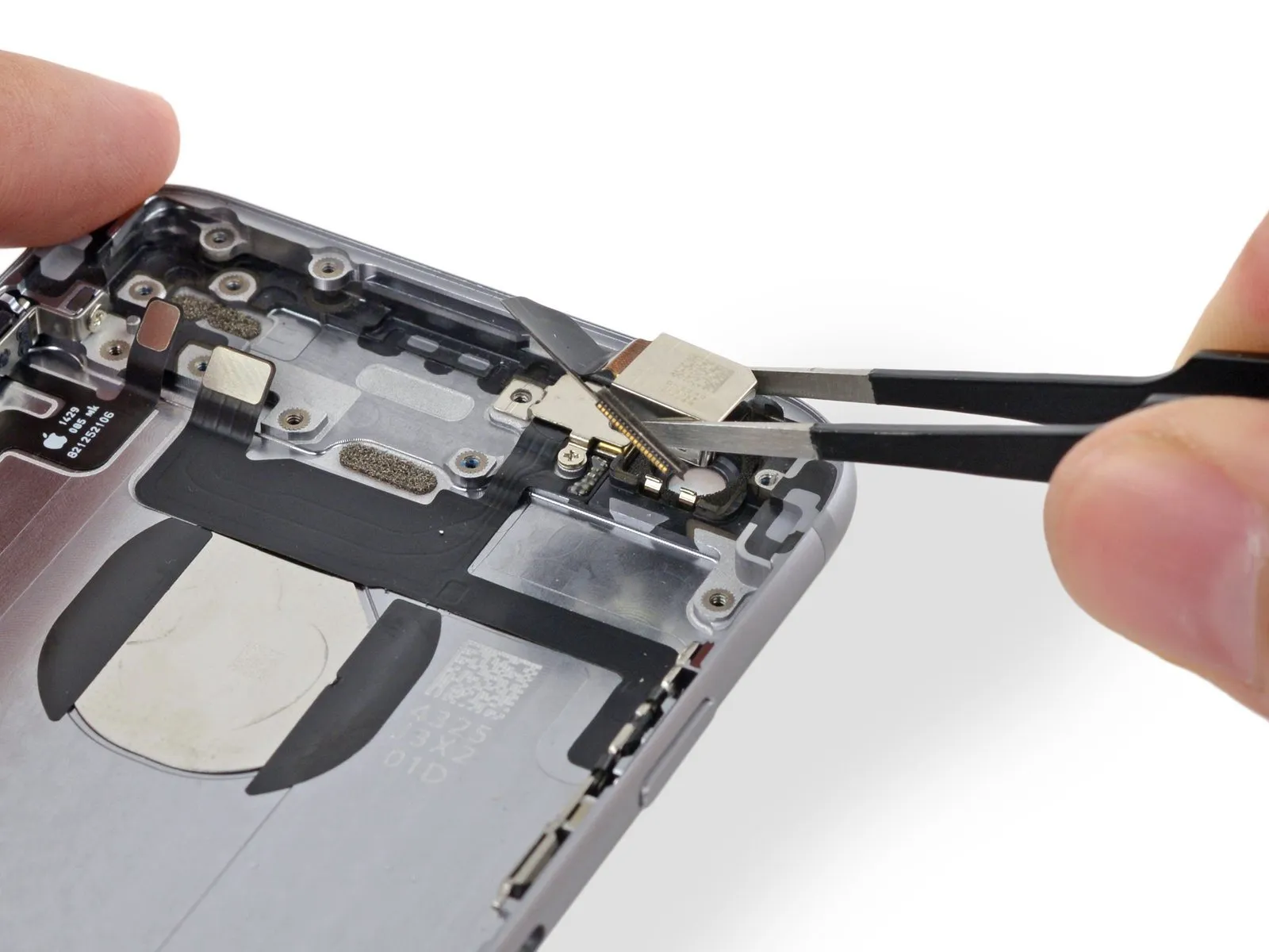
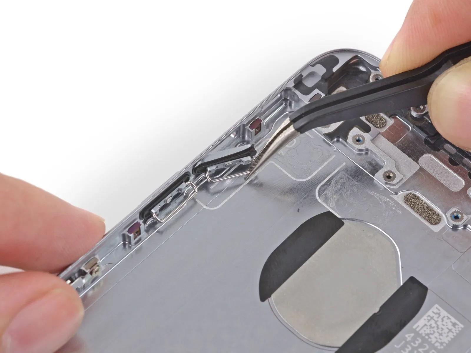
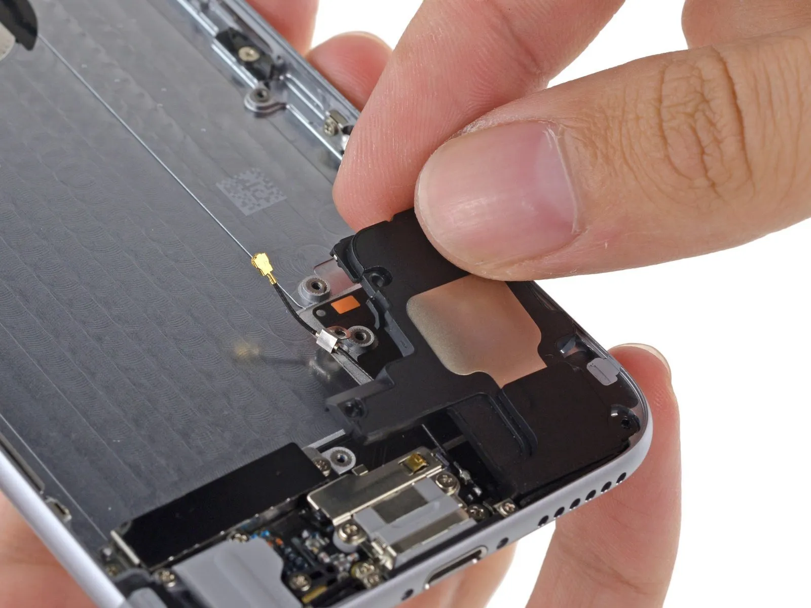
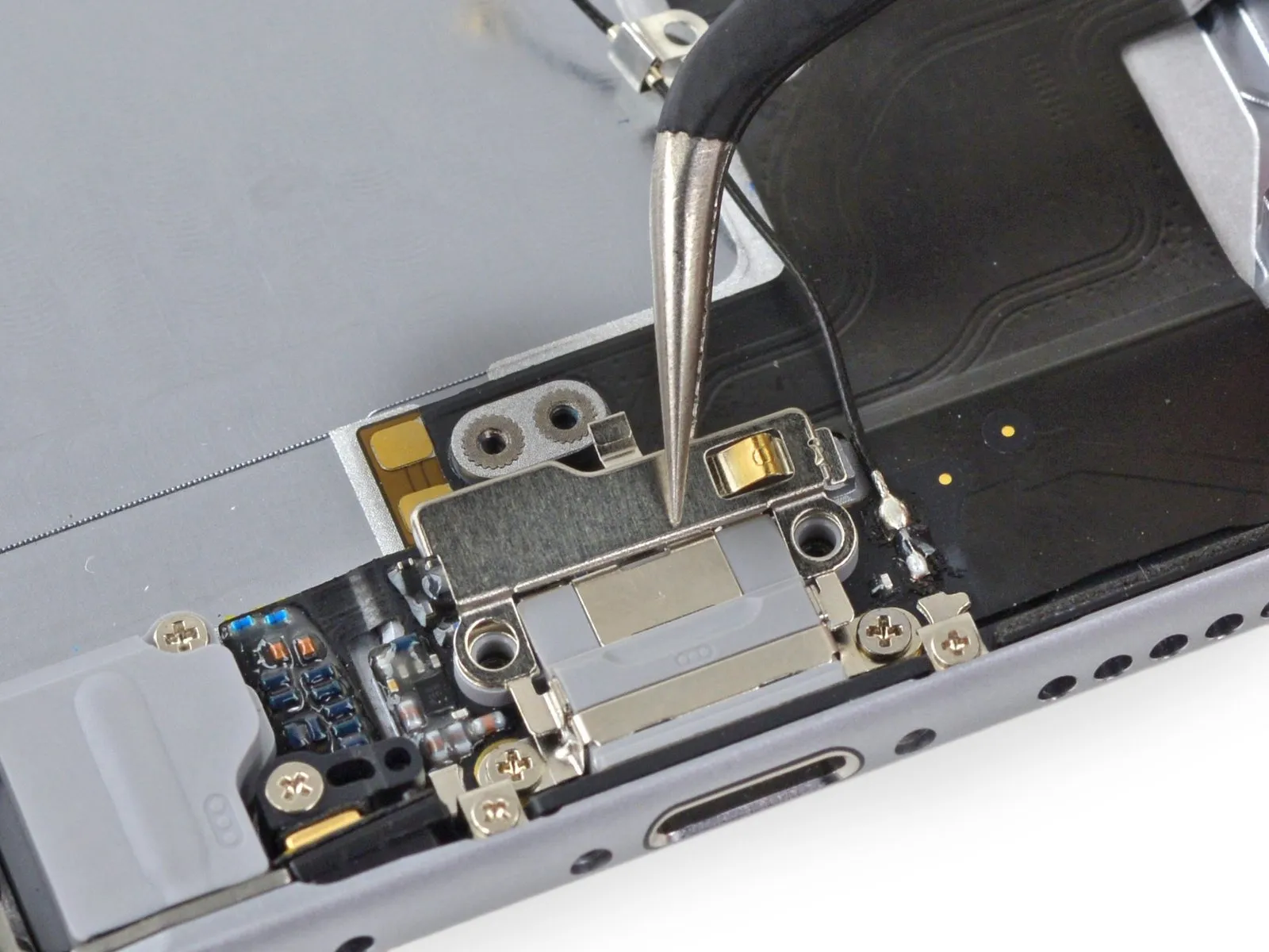
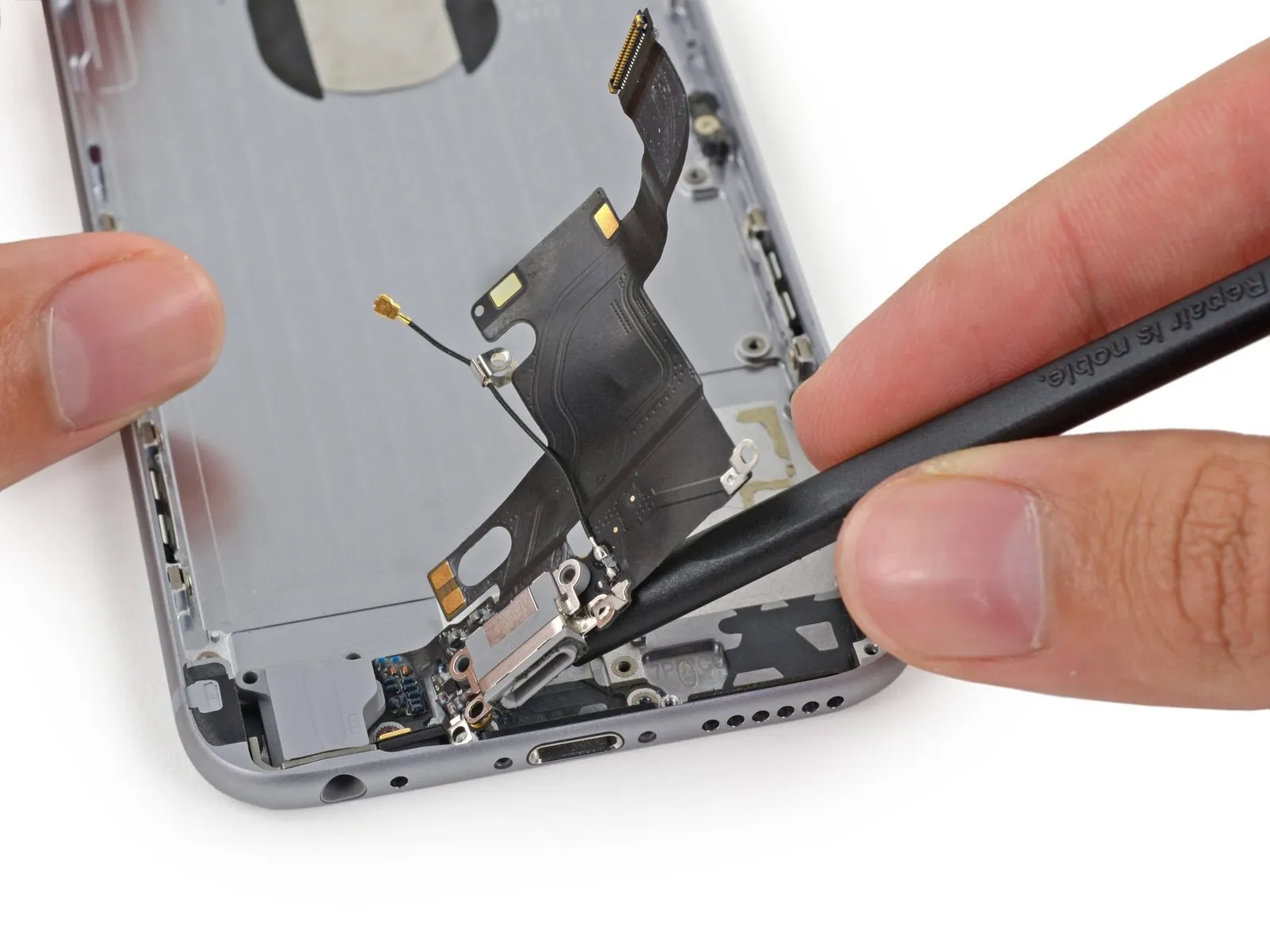
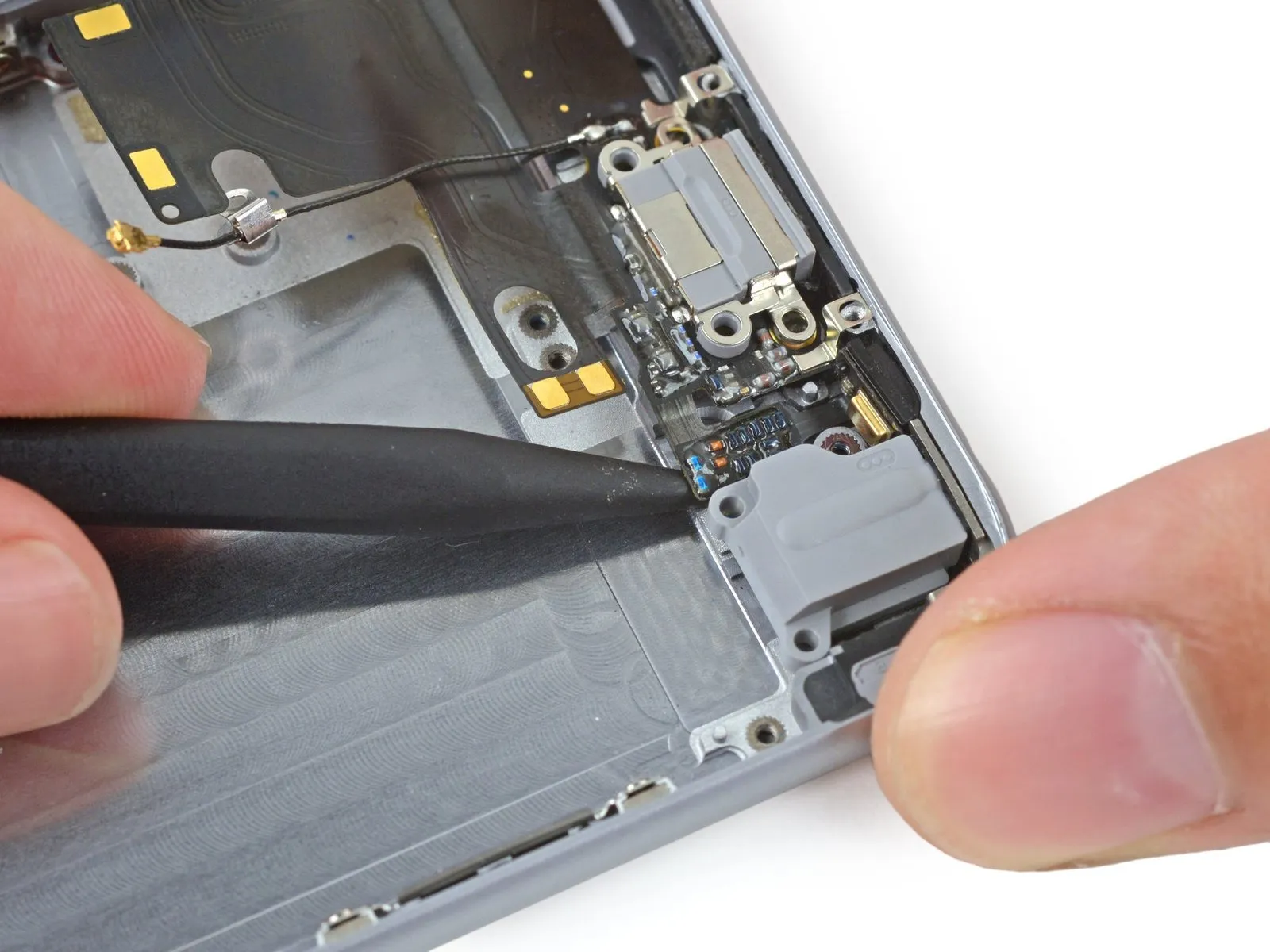
Carefully detach the Lightning connector assembly cable from its socket using the flat spudger, then maneuver it aside to avoid interference with the speaker.
Step 22

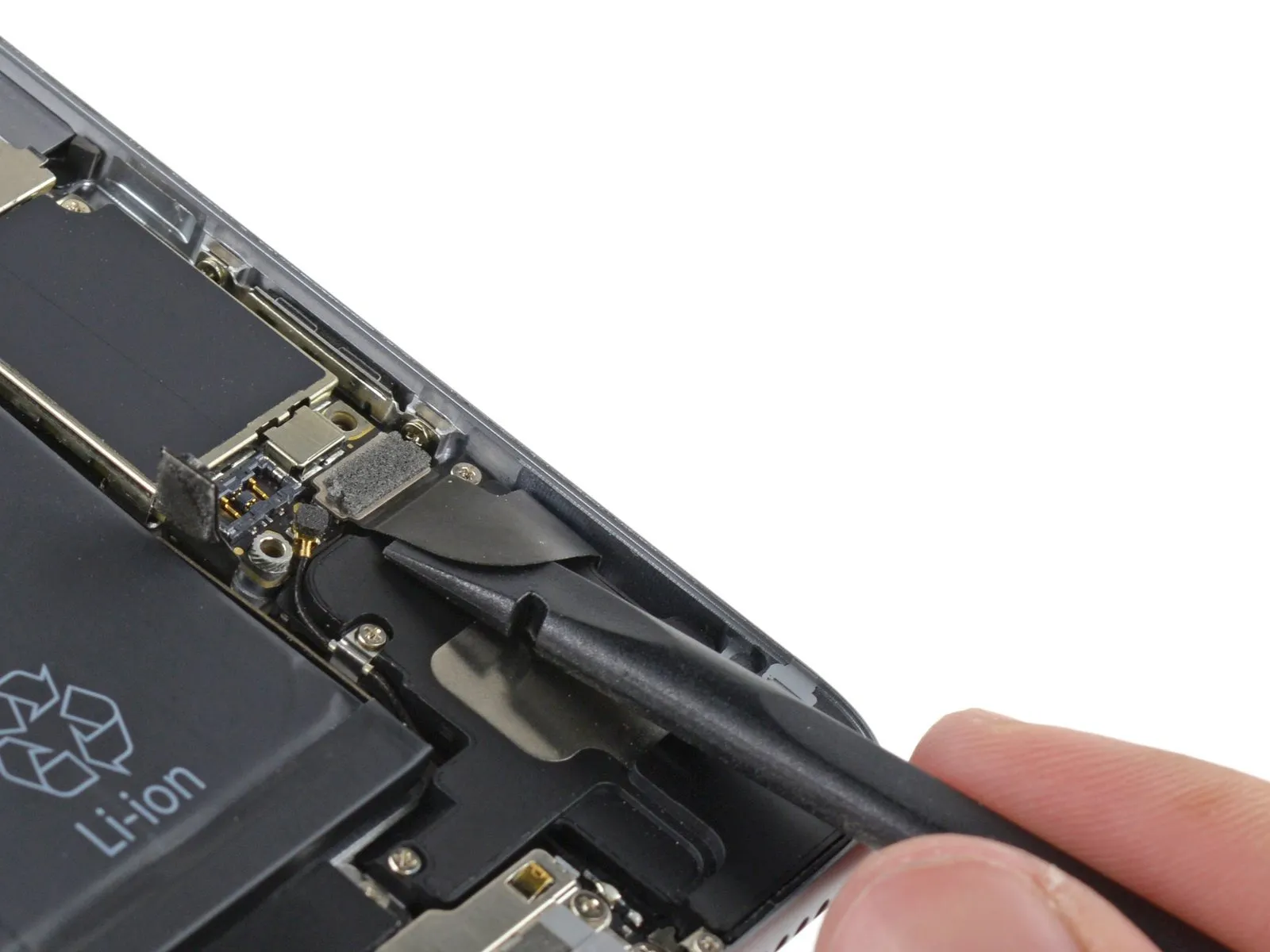
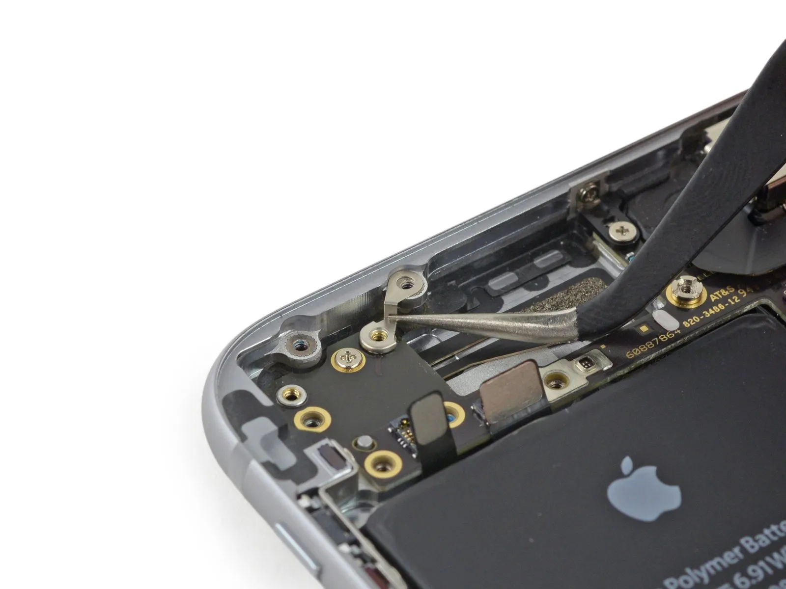
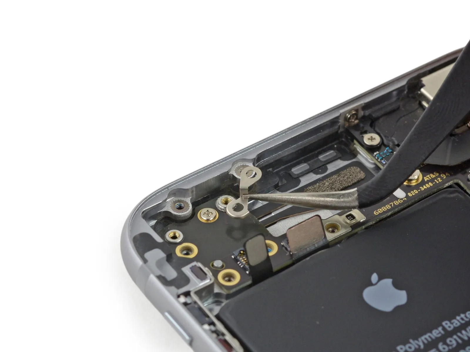
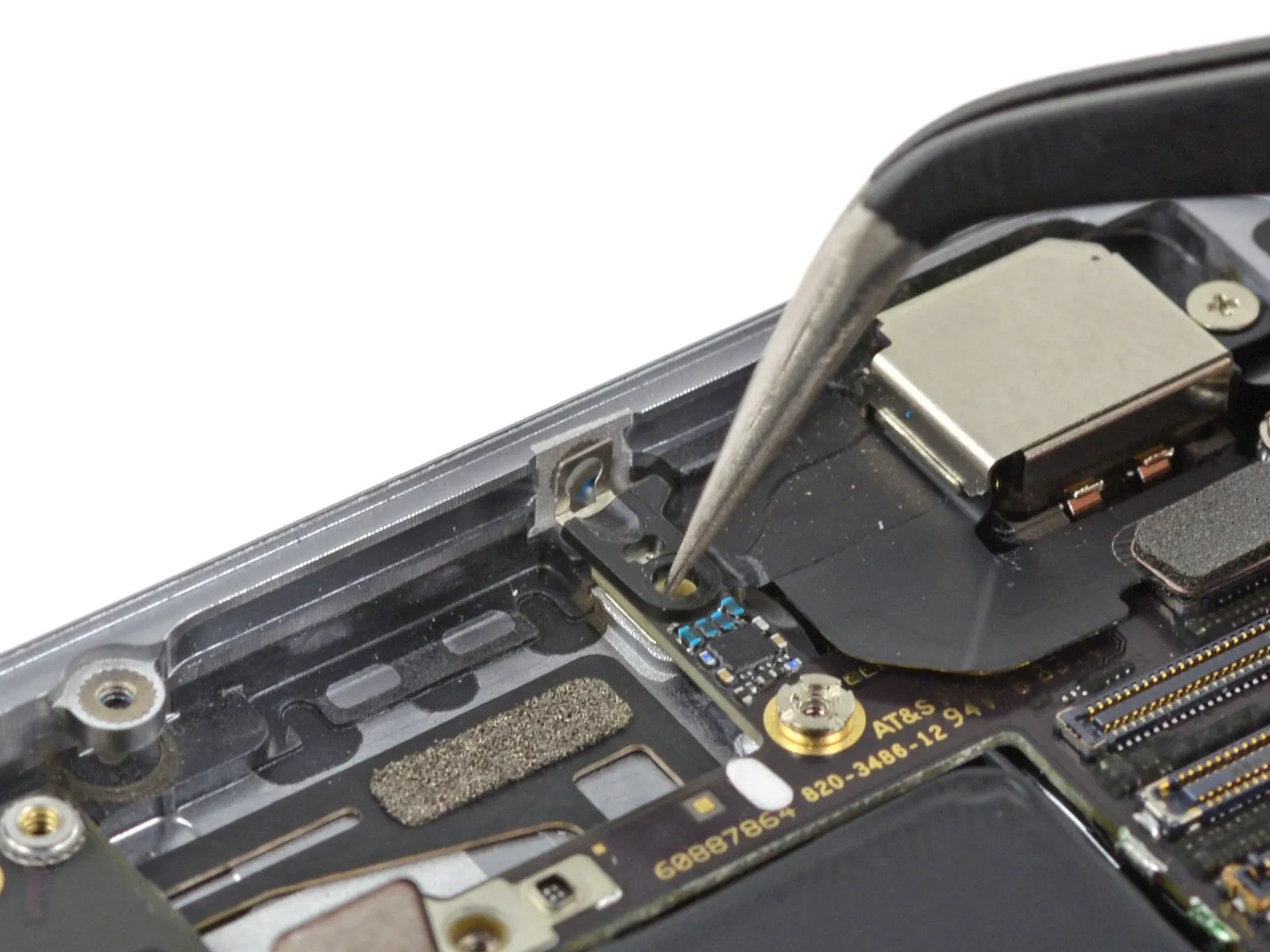
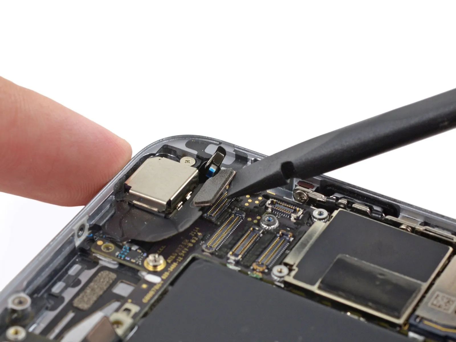
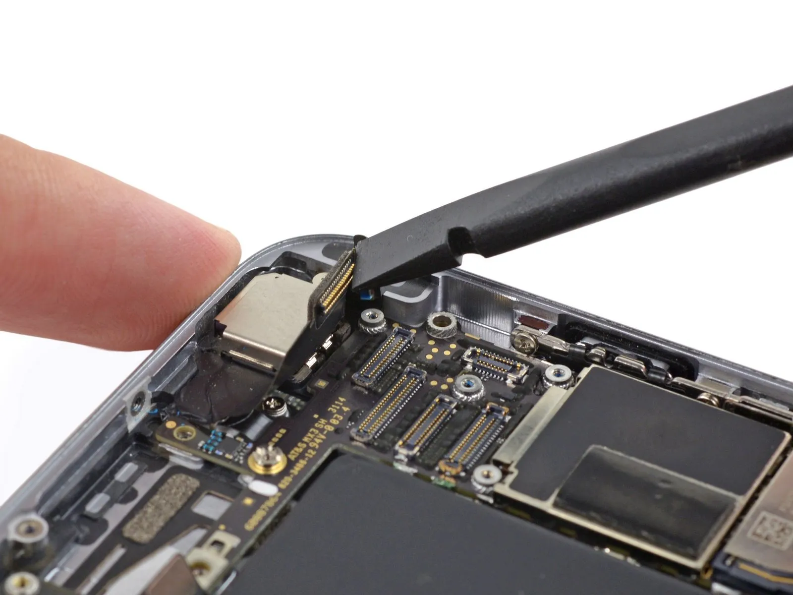
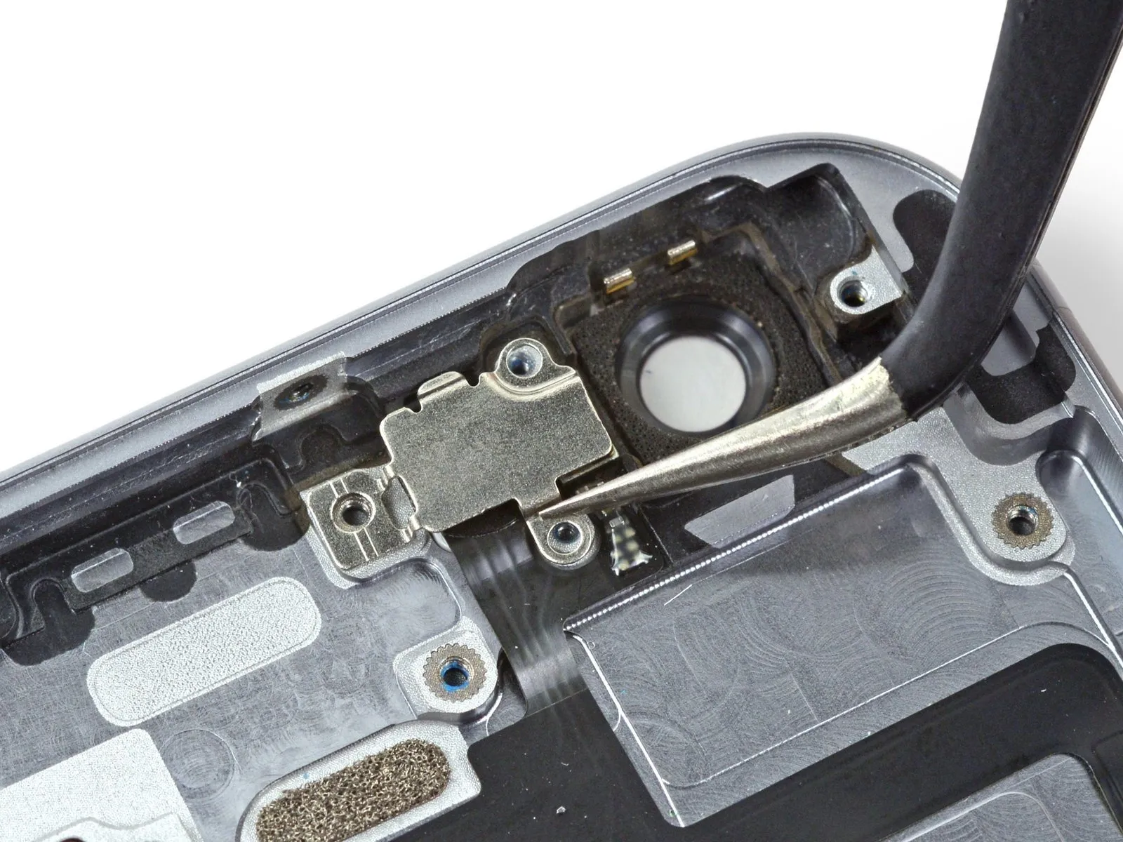
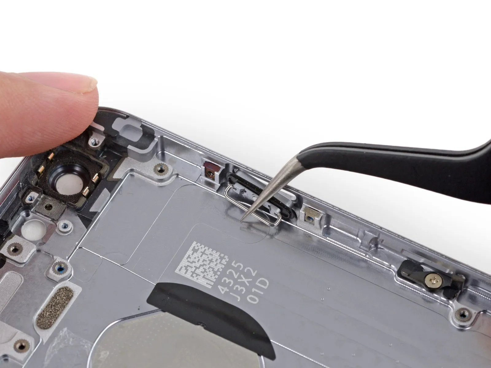
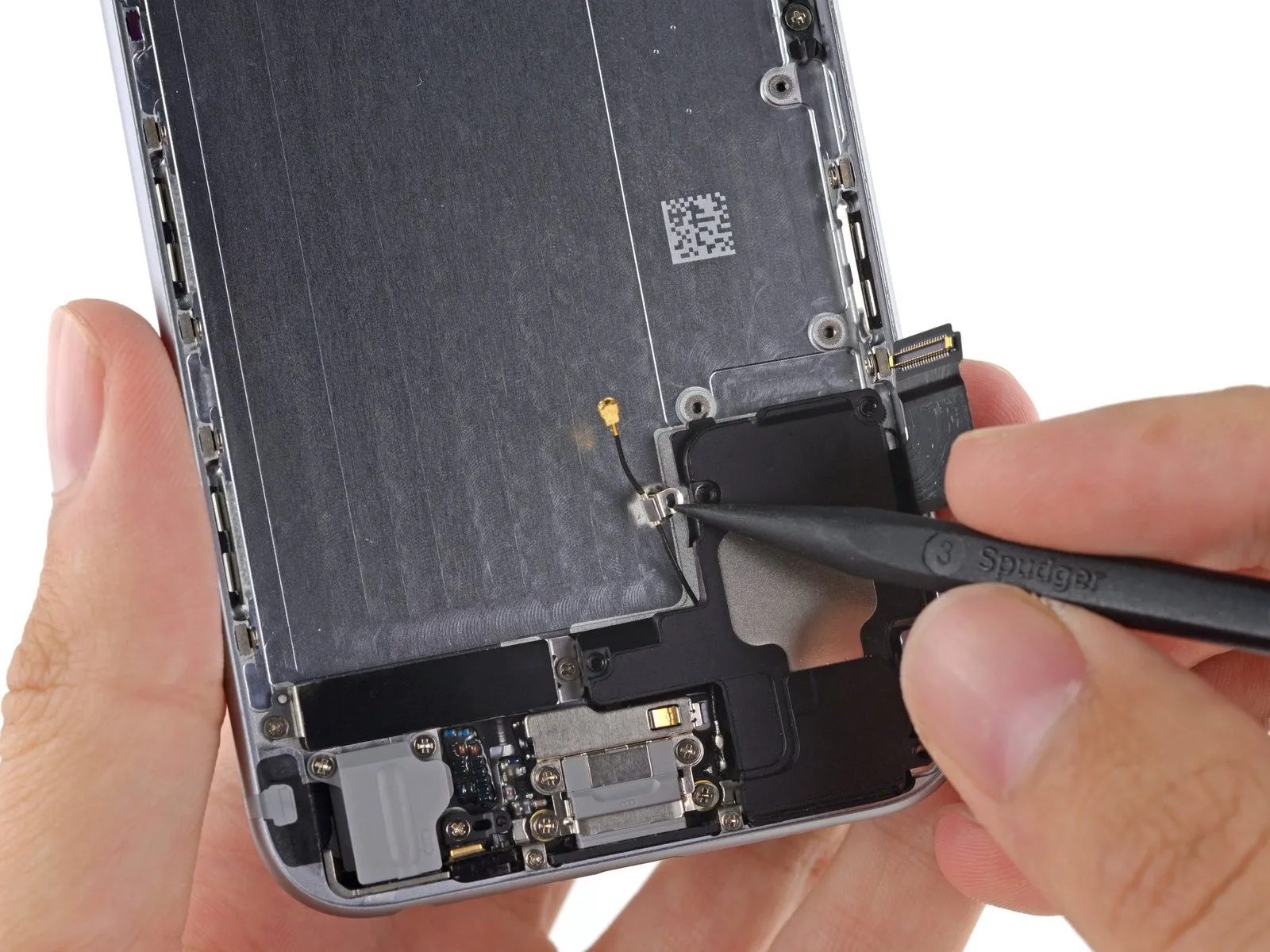
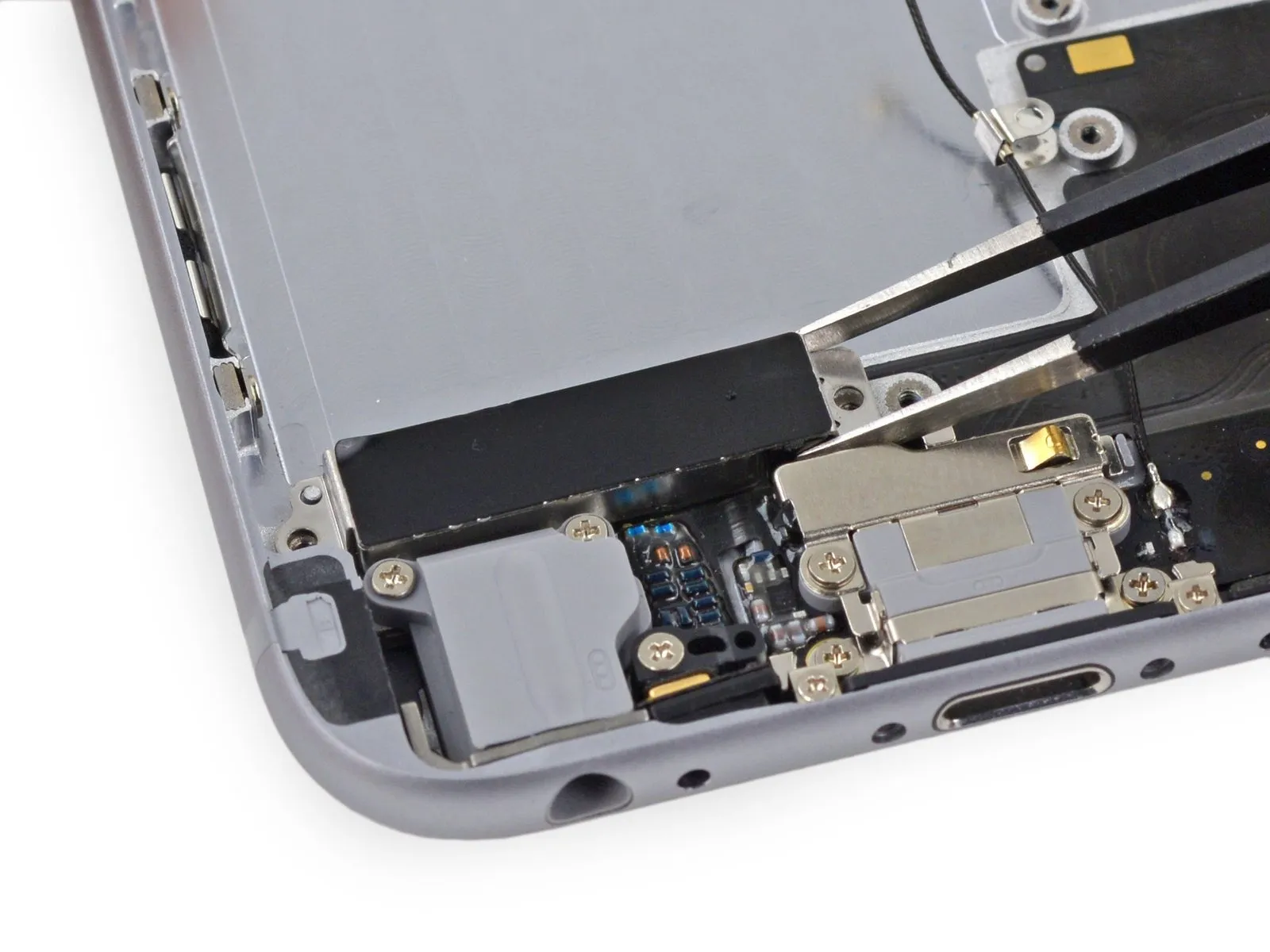
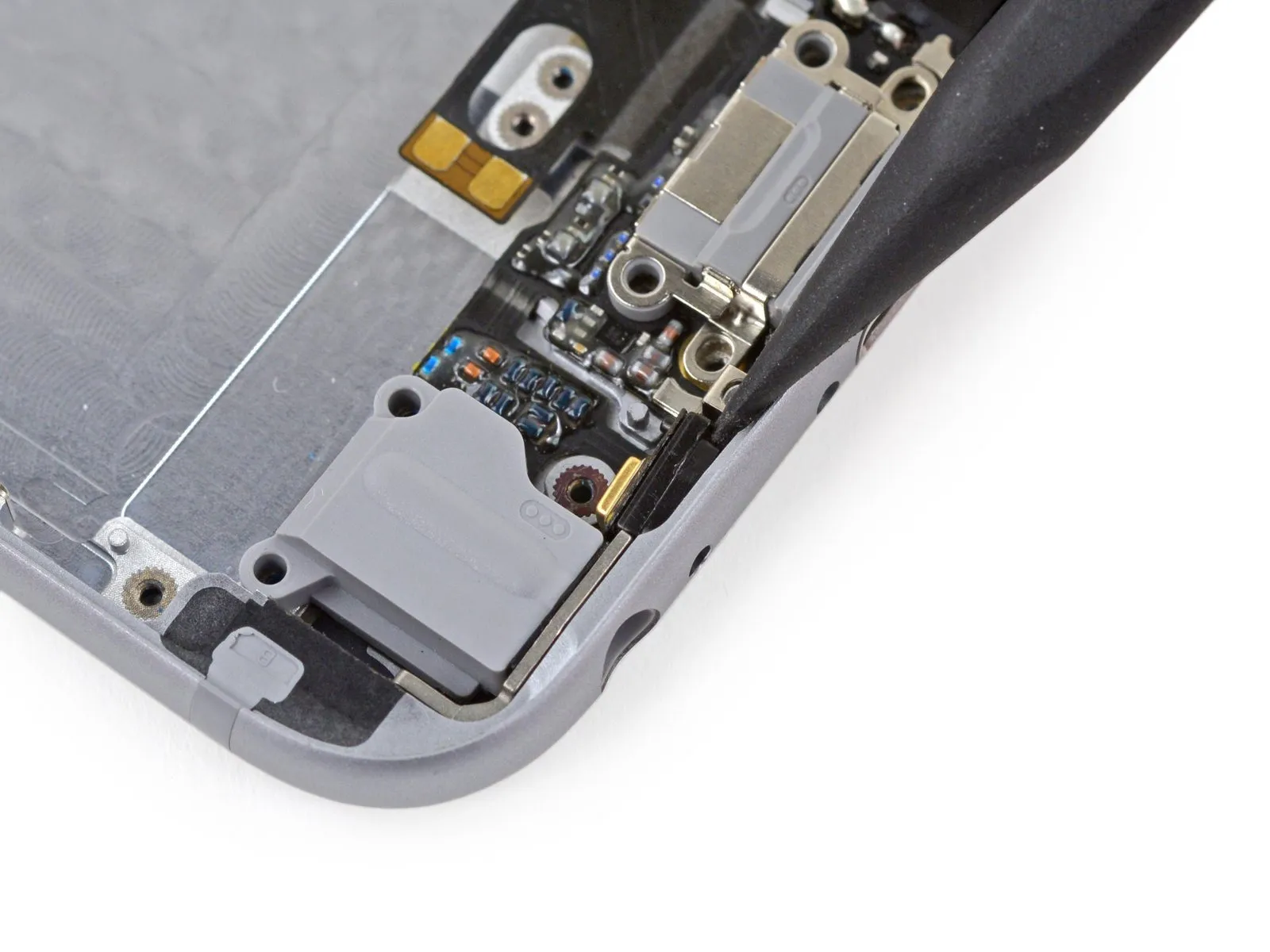
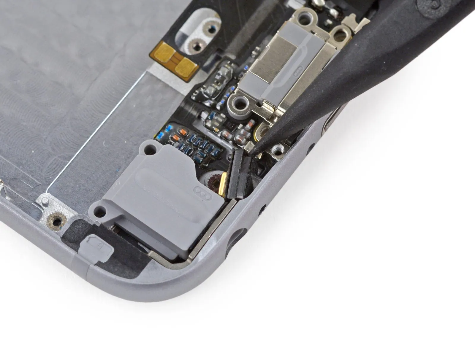
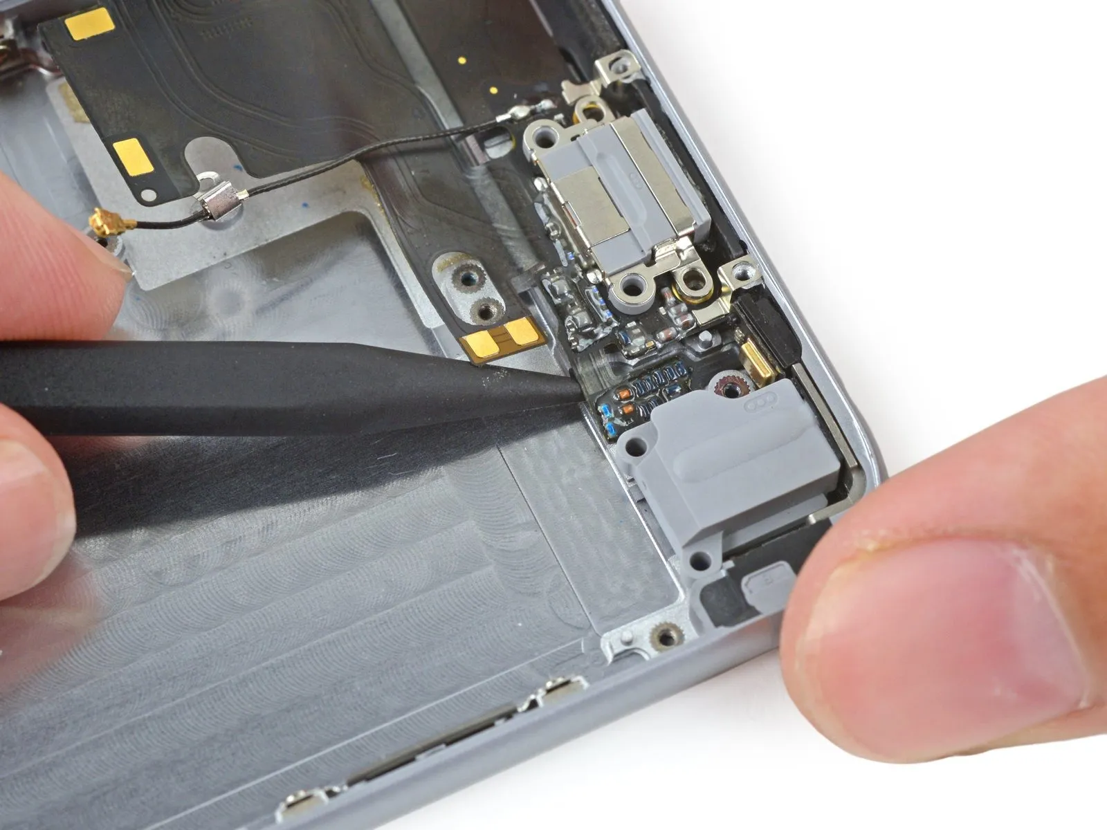
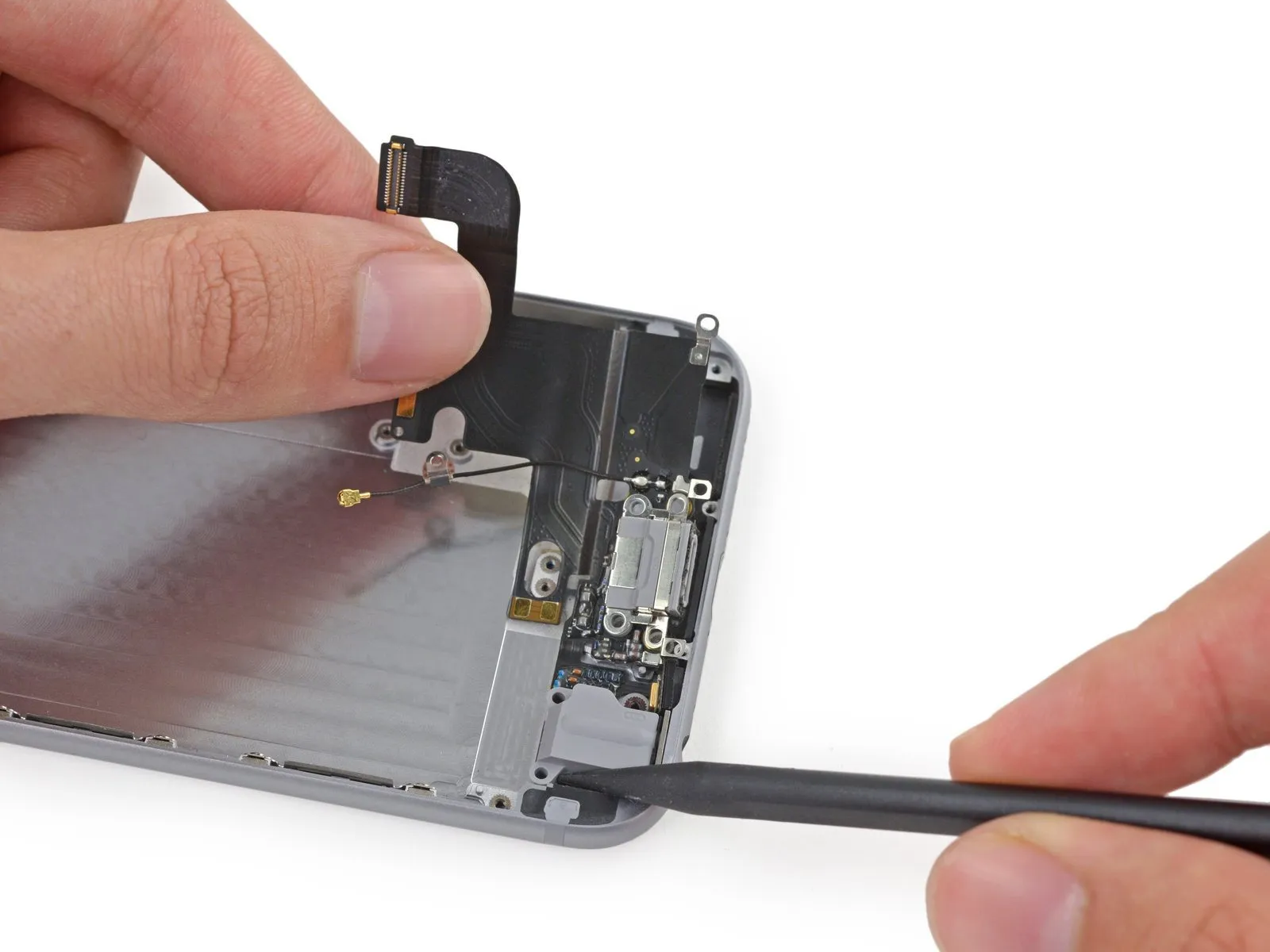
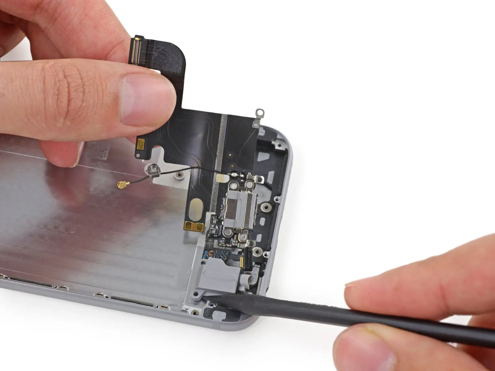
Carefully leverage the antenna cable connector away from its socket on the logic board using a spudger's tip.
Step 23
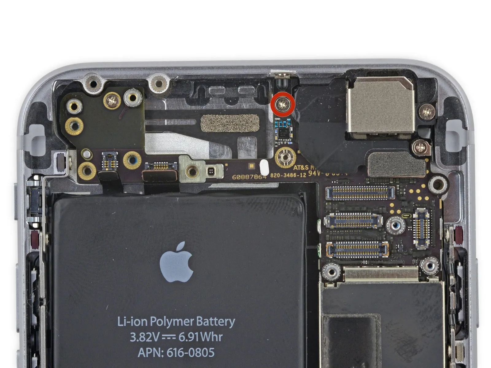
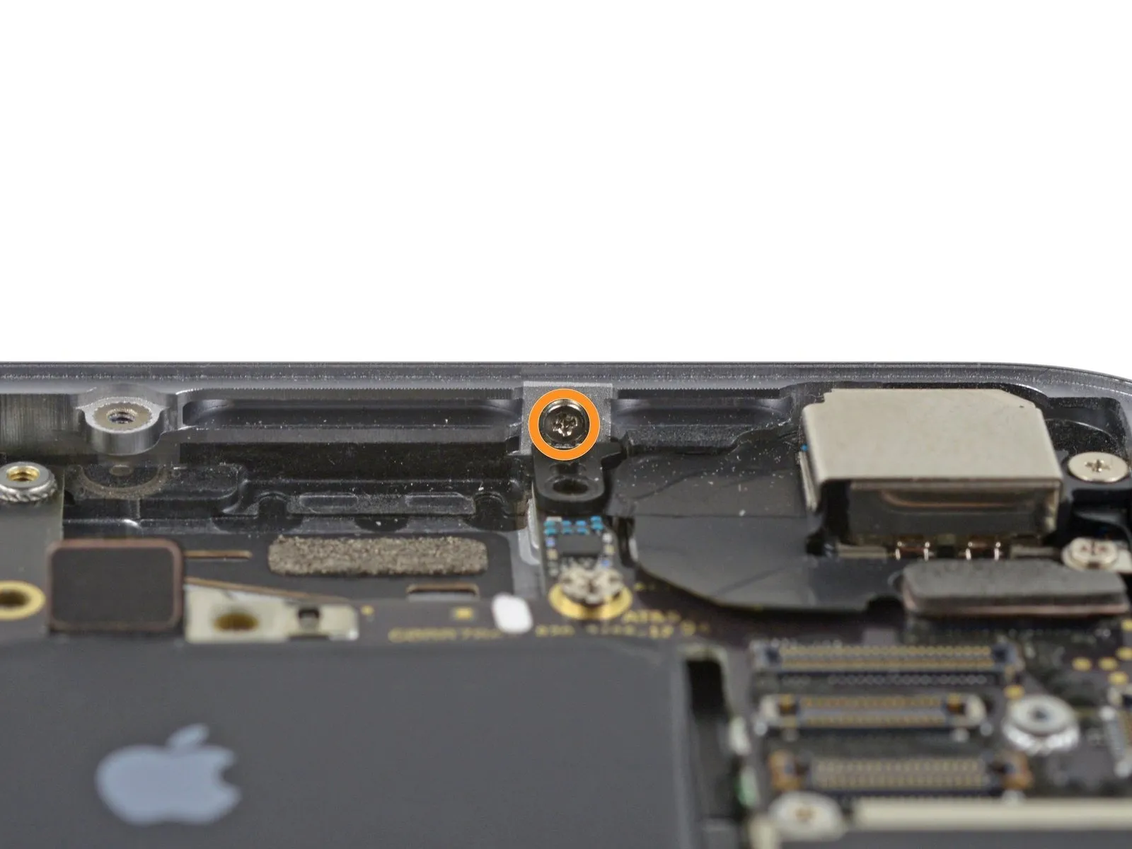
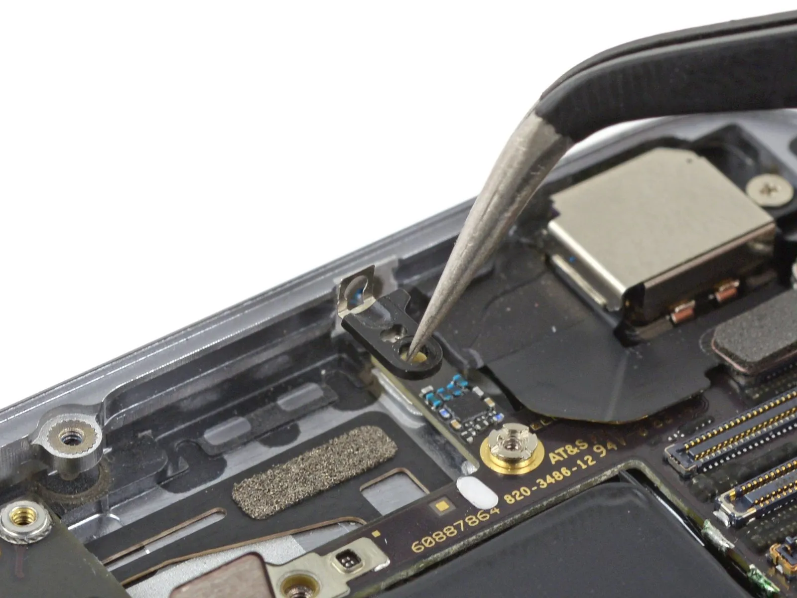
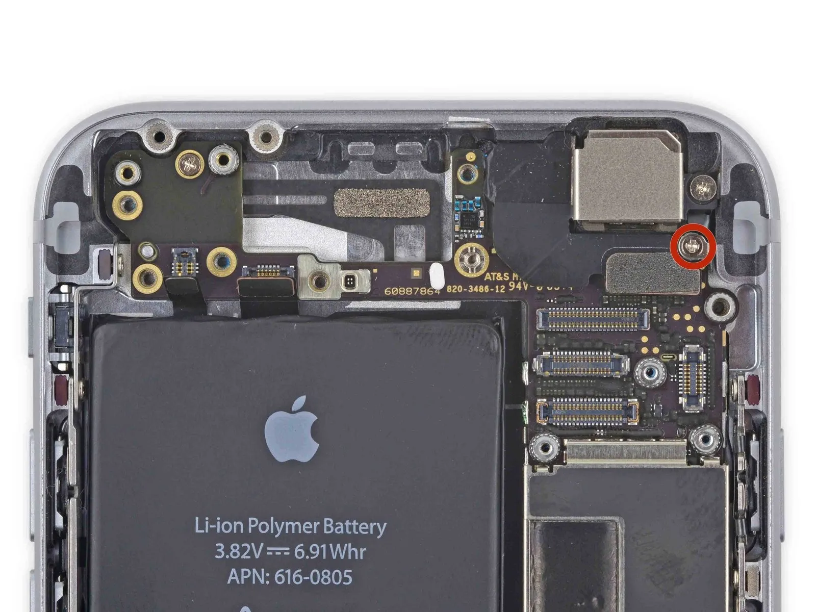
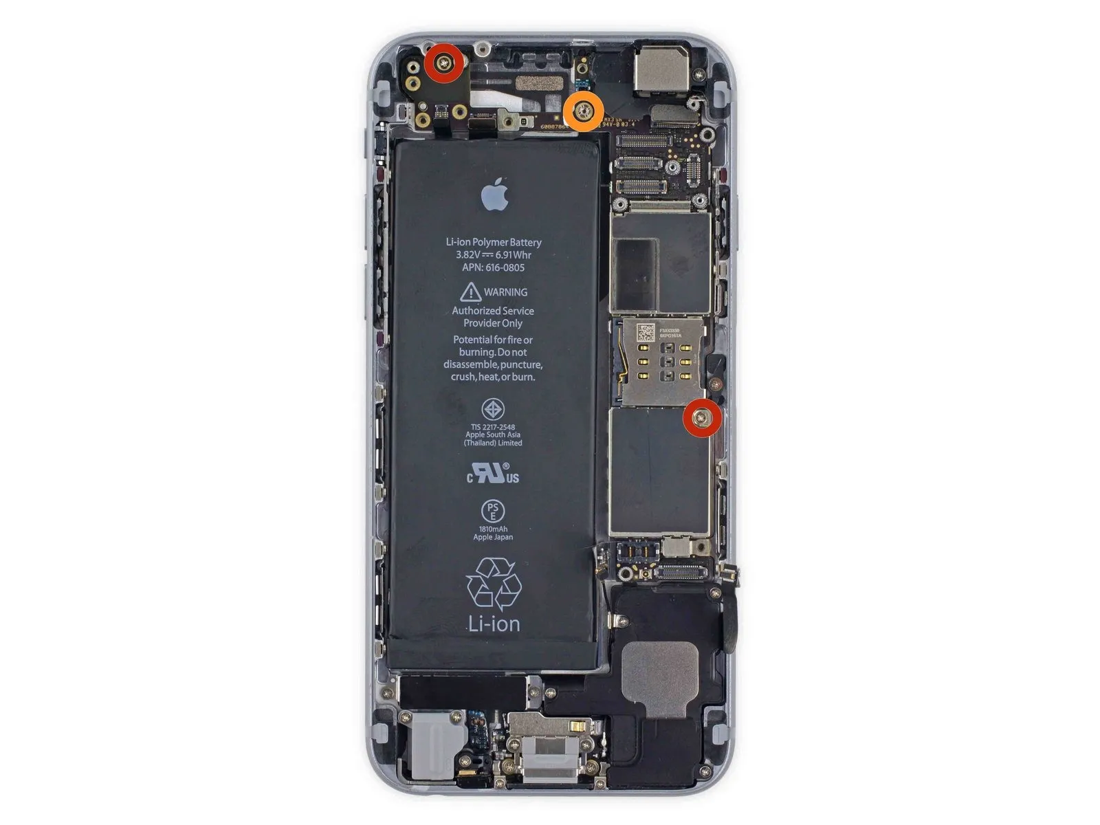
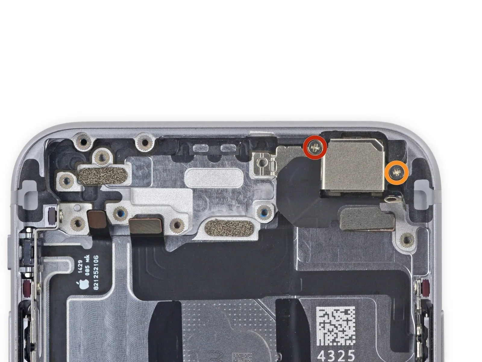
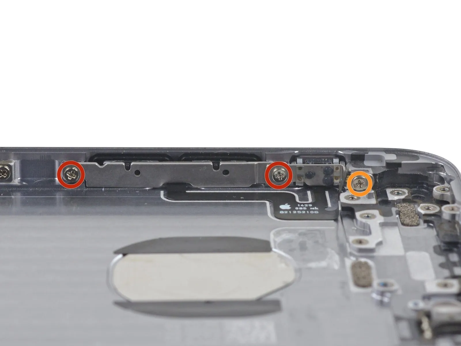
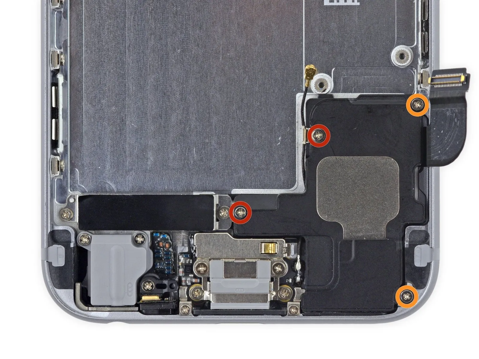
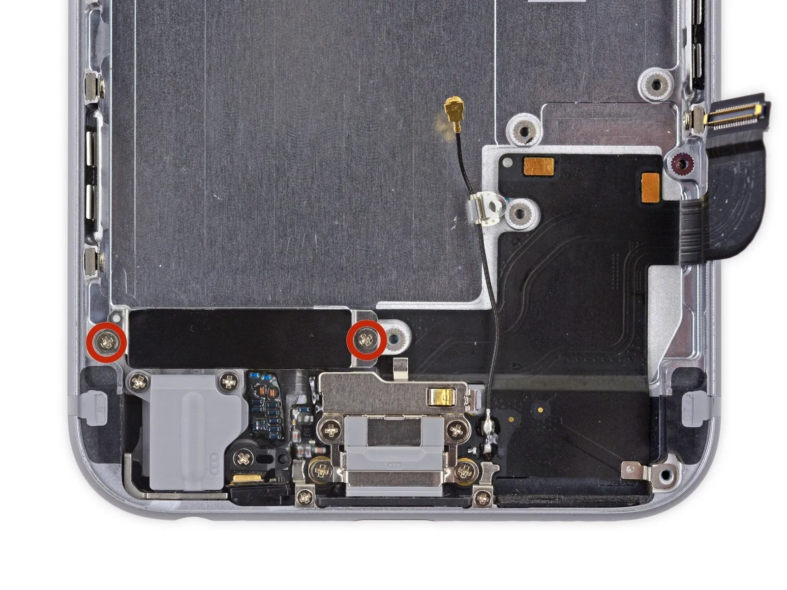
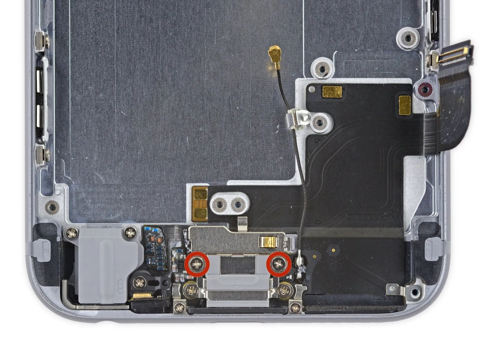
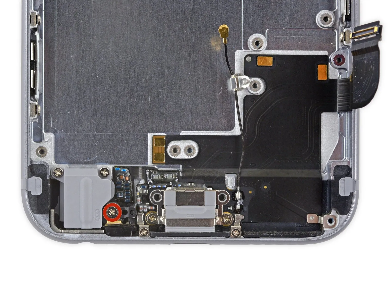
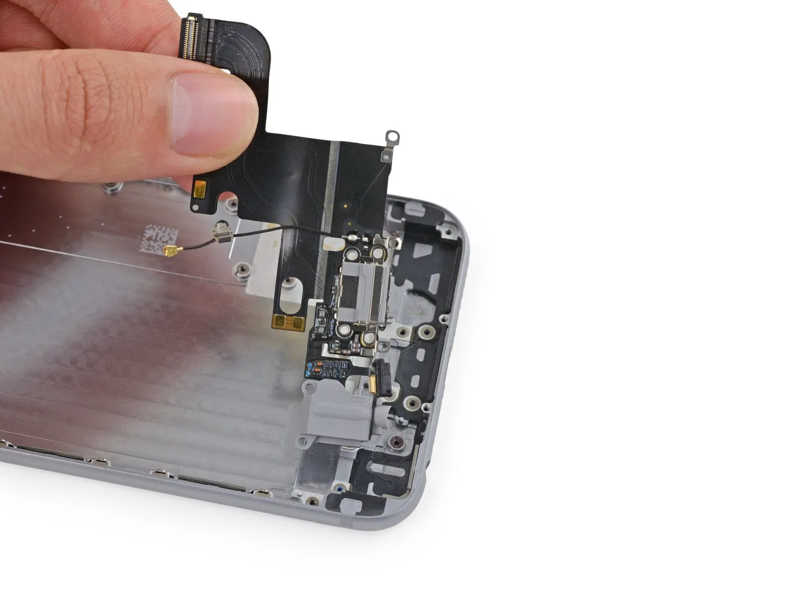
Using a Phillips screwdriver, detach the upper cable bracket by unscrewing the included fasteners.
A screw with a 2.9 mm diameter is required.
A screw with a 2.2 mm diameter is required.
A screw with a 2.9 mm diameter is required.
A screw with a 2.2 mm diameter is required.
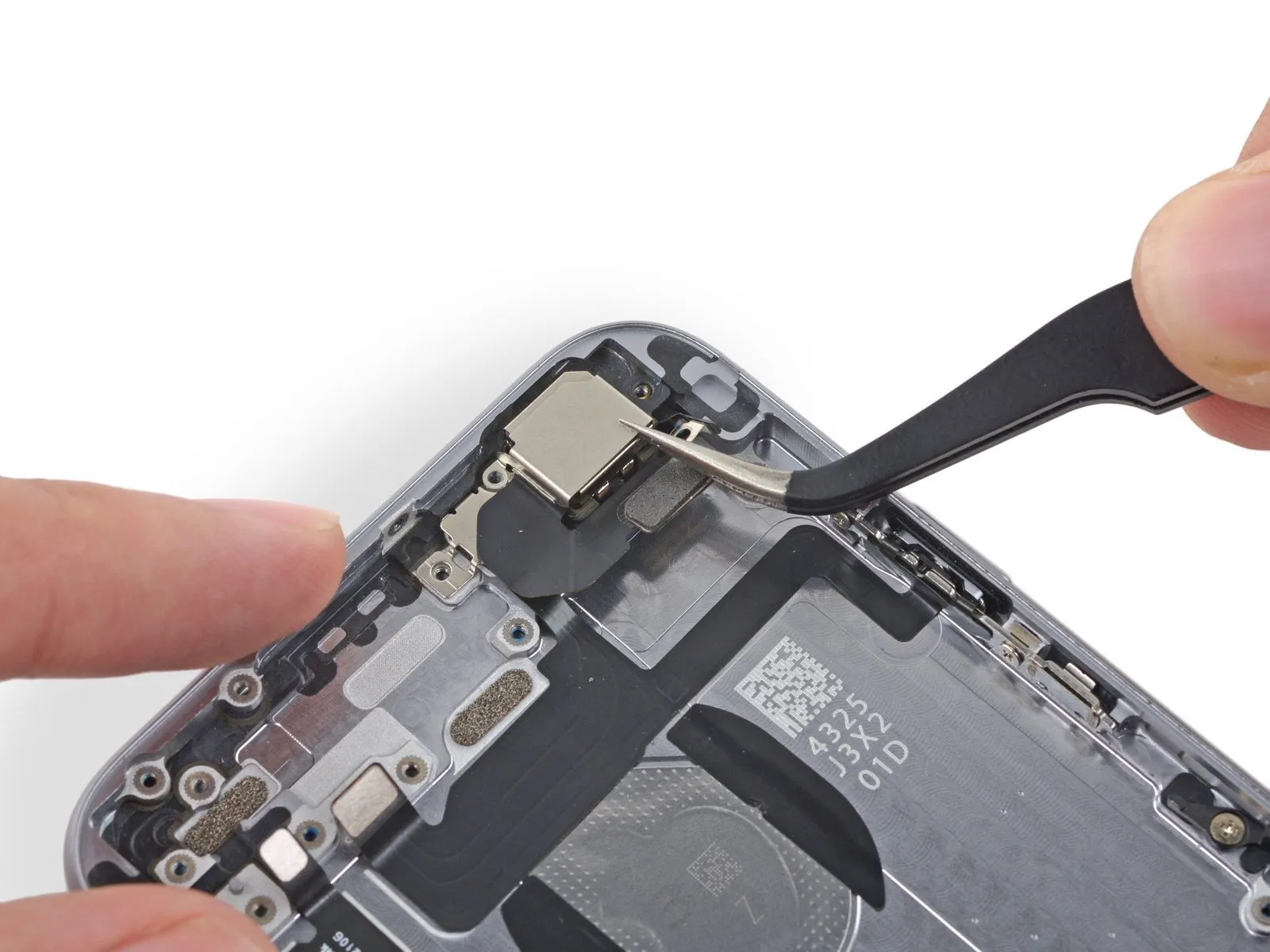
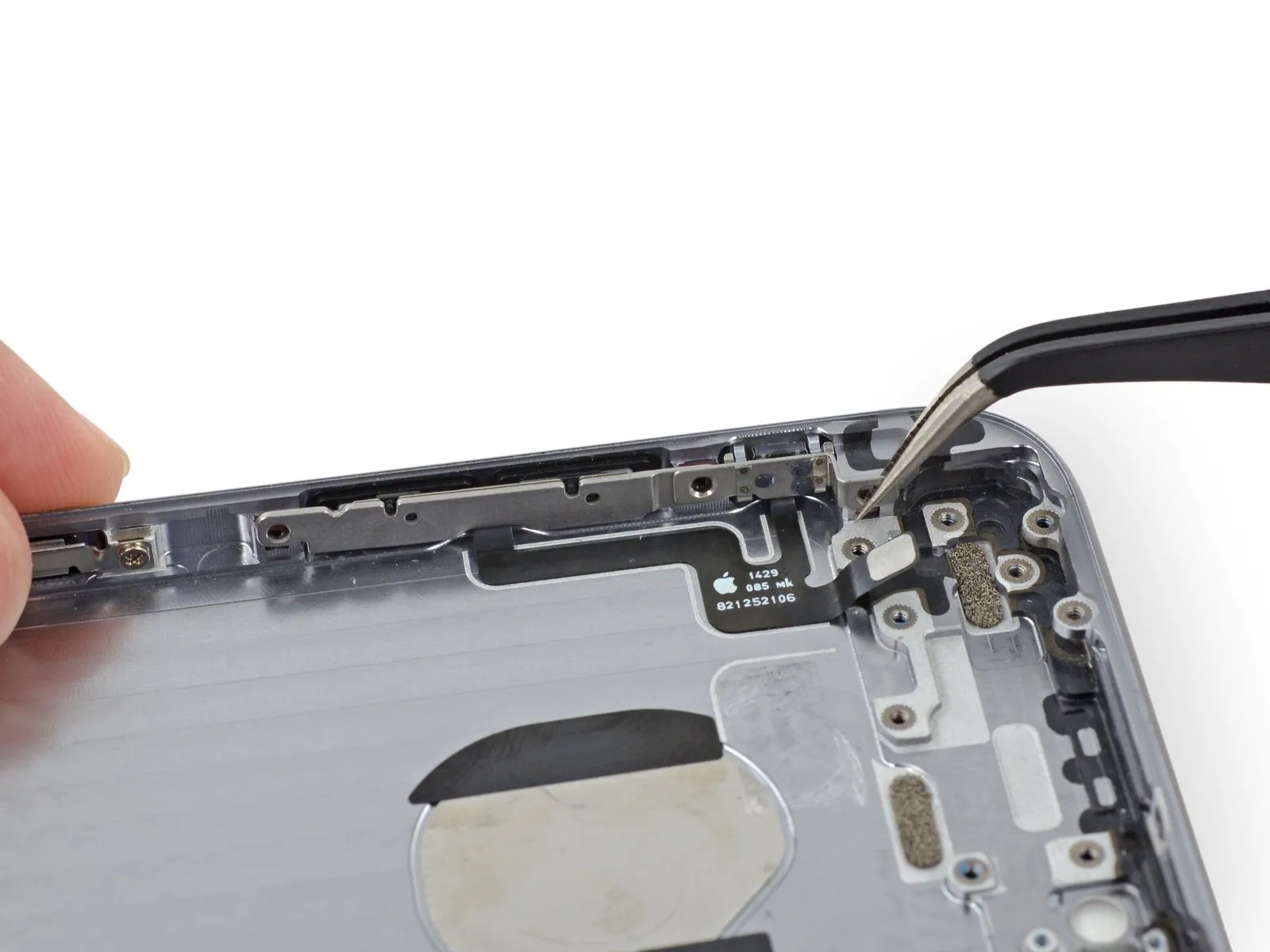
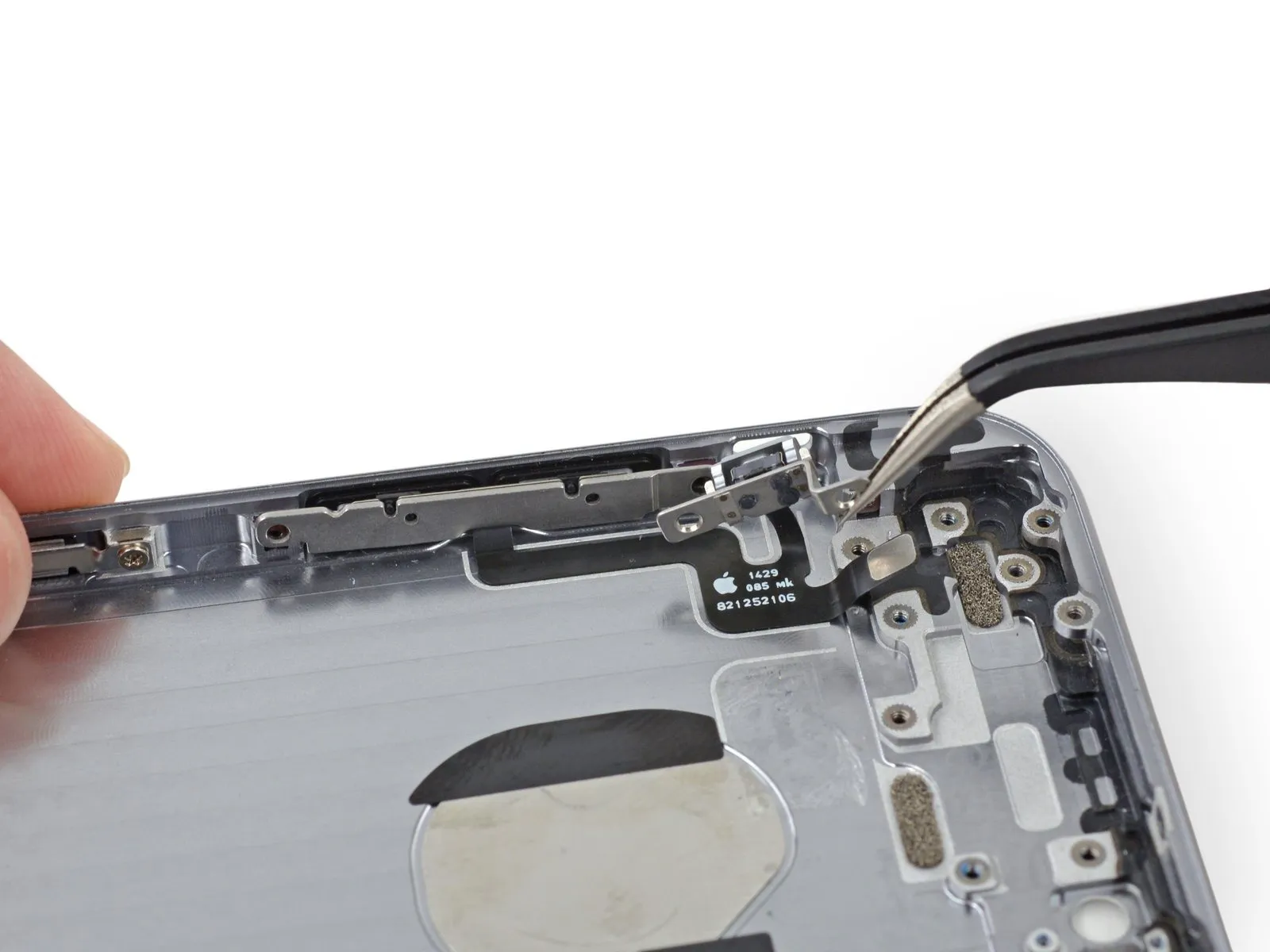
Step 24
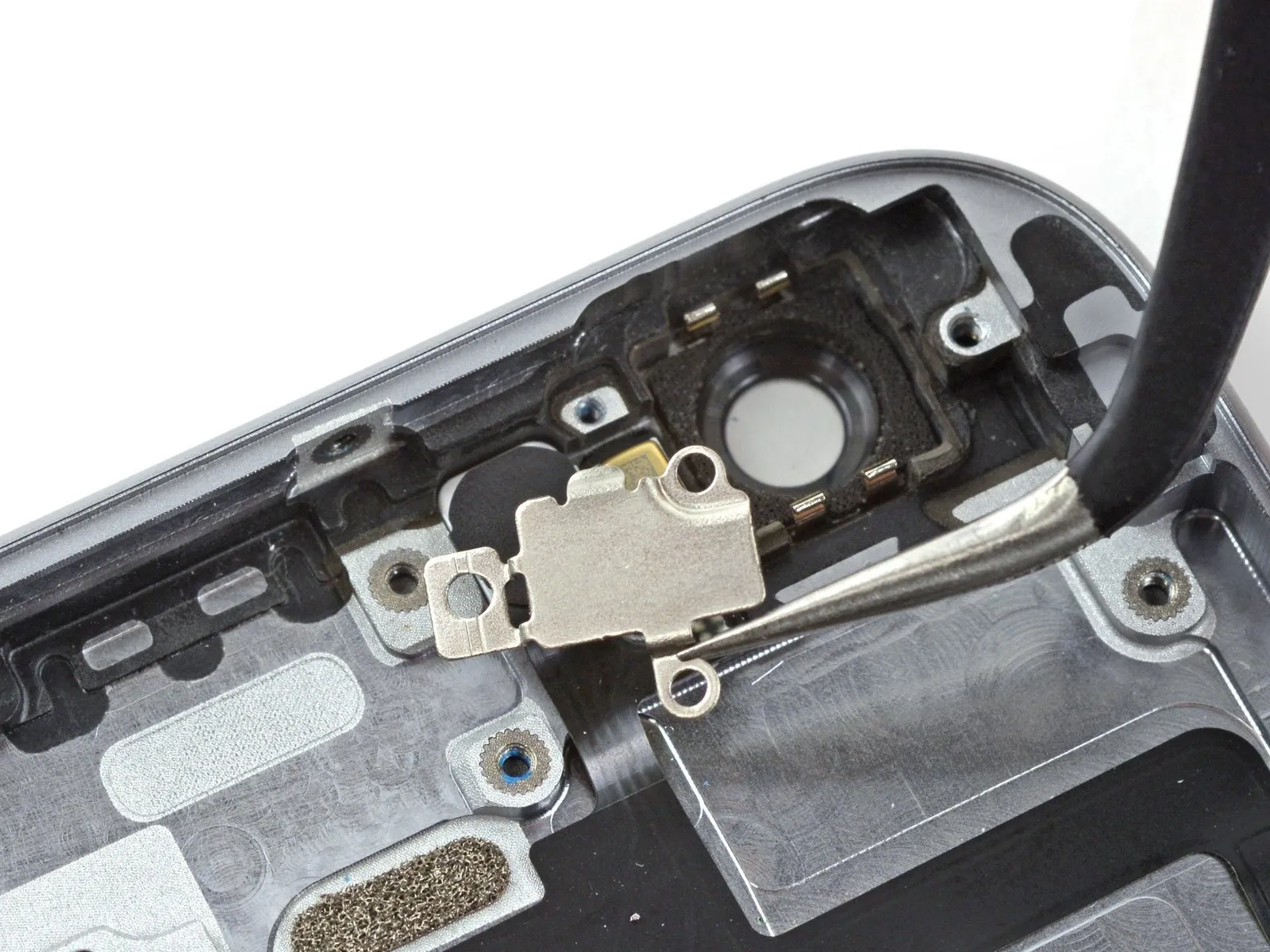
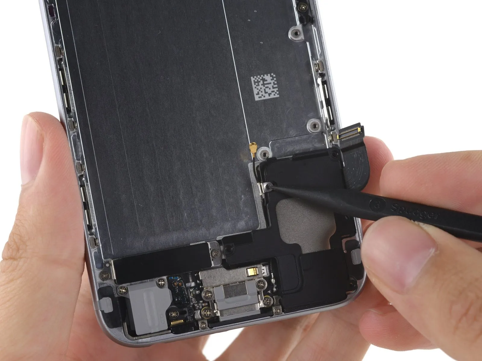
Detach the iPhone's upper cable bracket.
Step 25

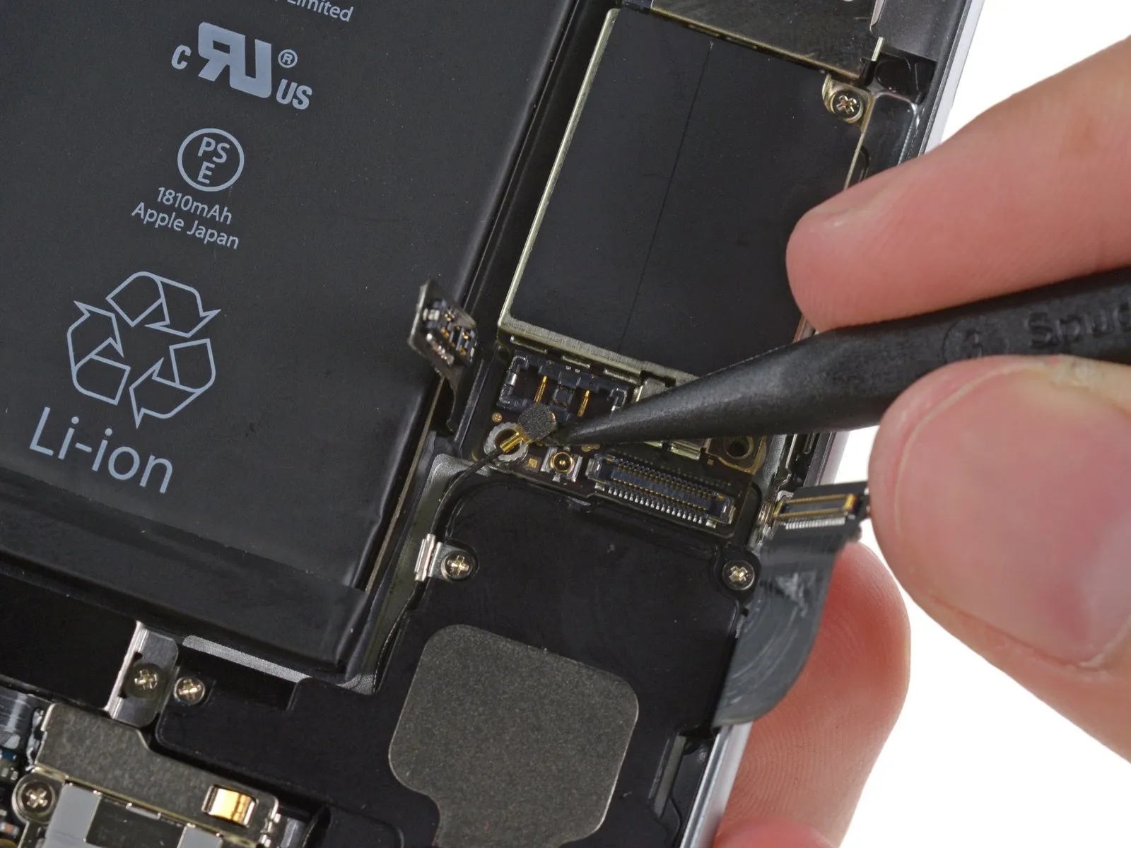
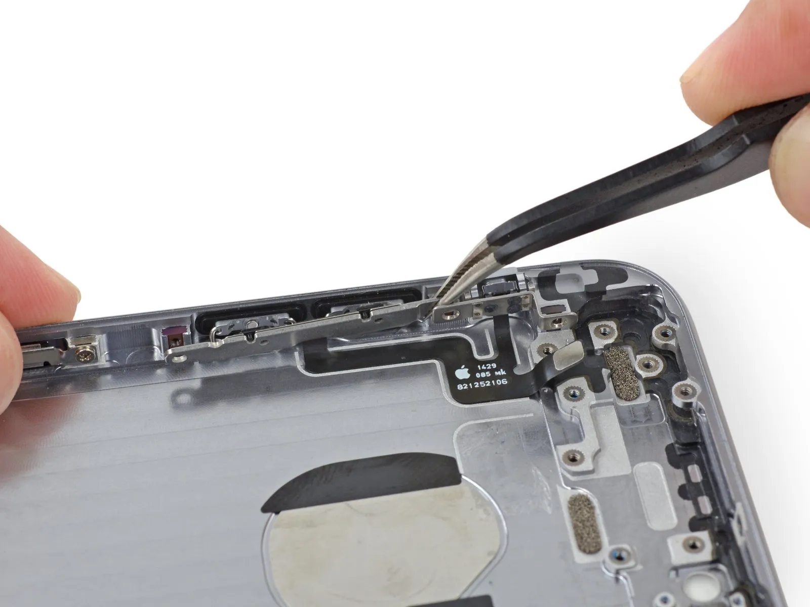
To avoid irreversible harm, carefully separate connectors by applying pressure only to the connector body itself, never the corresponding socket on the logic board.
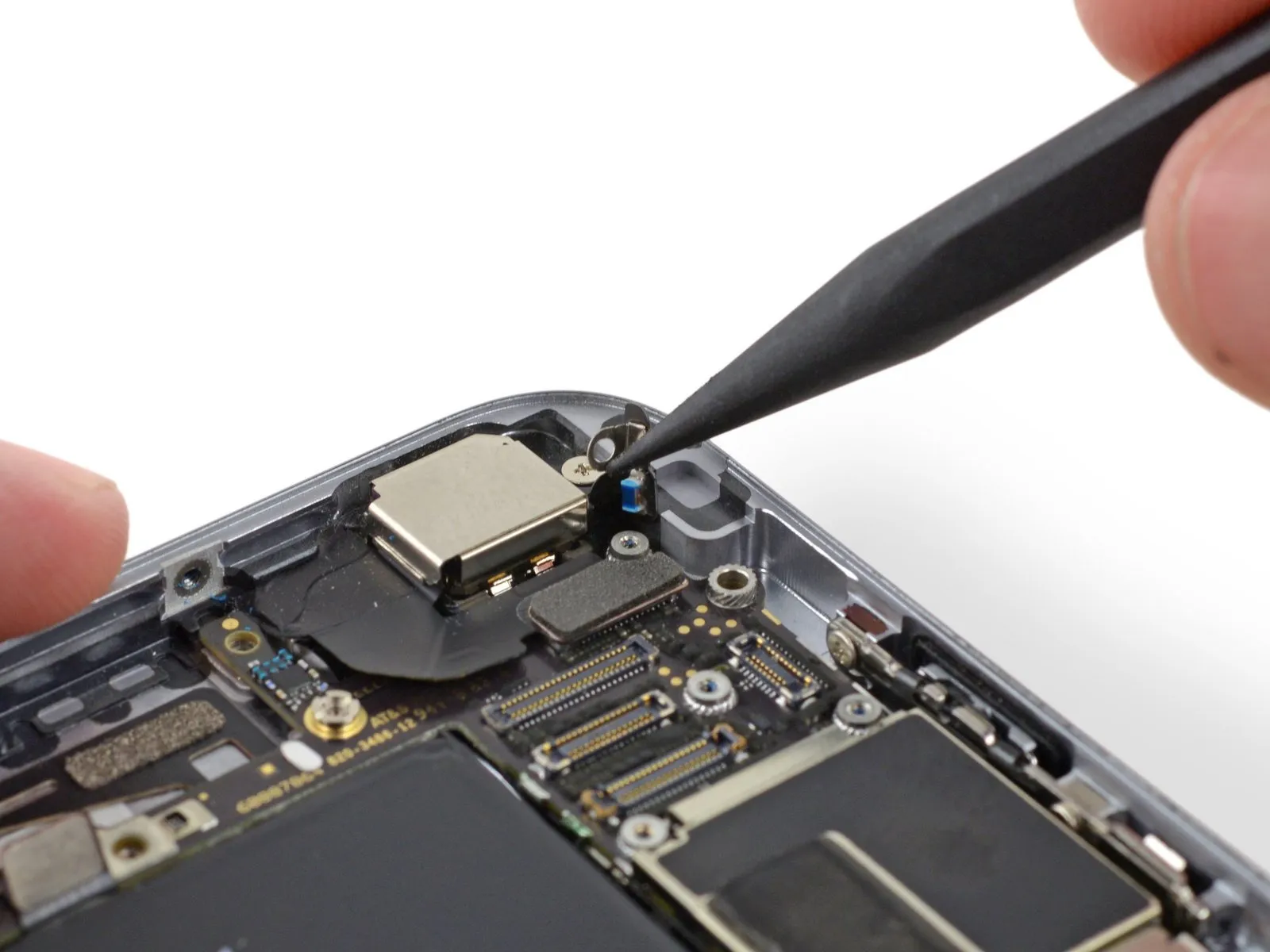
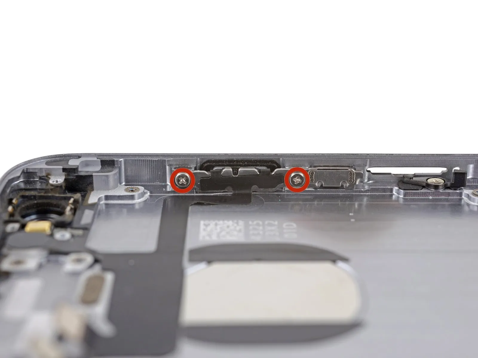
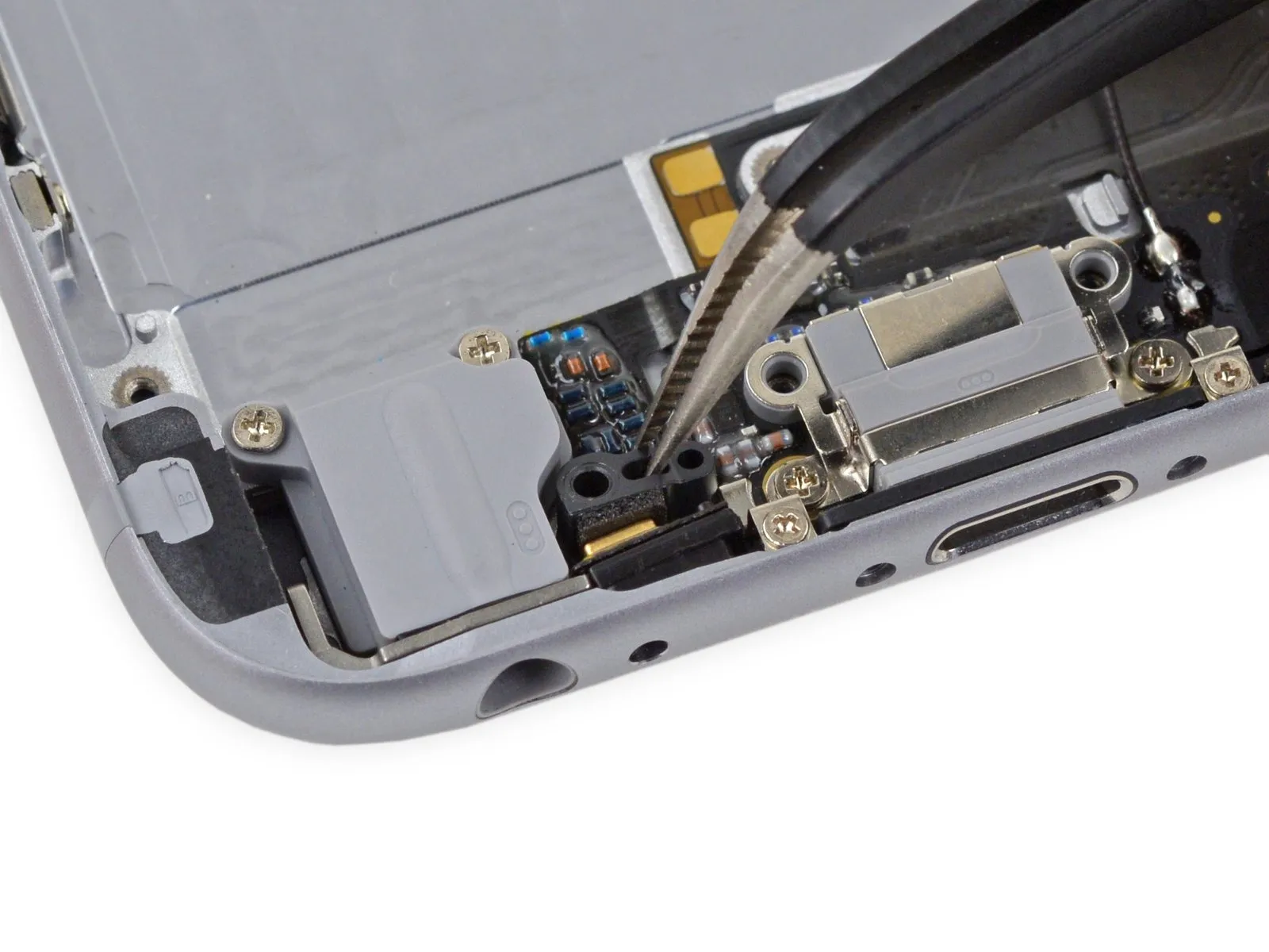
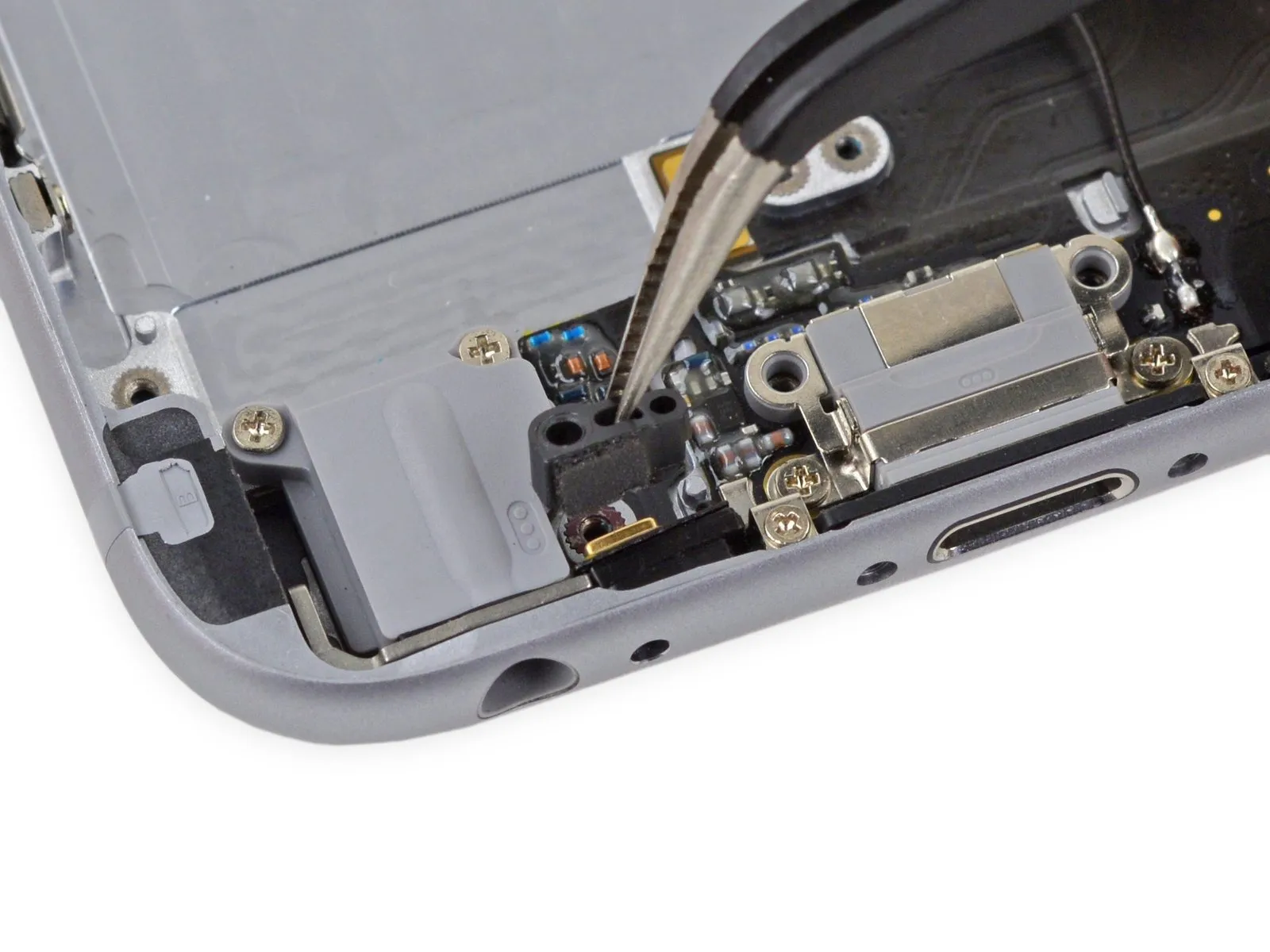
Carefully employ the flat spudger tip to disengage the power button and flash assembly cable connector from its socket.
Carefully detach the volume control cable connector from its corresponding socket on the logic board.
Carefully employ the flat spudger tip to disengage the power button and flash assembly cable connector from its socket.
Carefully detach the volume control cable connector from its corresponding socket on the logic board.
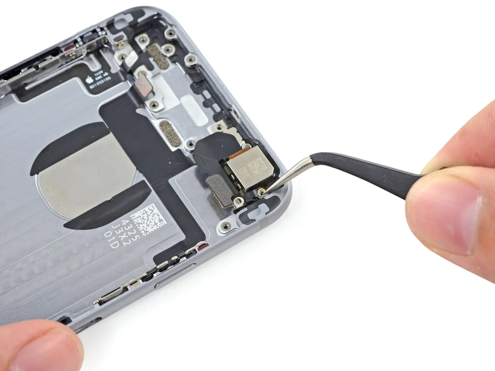
Step 26
Using a Phillips screwdriver, detach the four screws securing the Wi-Fi antenna.
A screw with a 1.5 mm head diameter is required.
A screw with a 1.4-millimeter head diameter is required.
Use two screws, each measuring 2.1 millimeters.
A screw with a 1.5 mm head diameter is required.
A screw with a 1.4-millimeter head diameter is required.
Use two screws, each measuring 2.1 millimeters.
Step 27

Carefully detach the Wi-Fi antenna assembly from the iPhone.
To prevent conductivity issues caused by oils from your skin, avoid direct contact with metal-to-metal interfaces; utilize tweezers or gloves instead. Should contact occur, thoroughly clean those areas with a degreaser, such as Windex or isopropyl alcohol, prior to reassembling the device.
To prevent conductivity issues caused by oils from your skin, avoid direct contact with metal-to-metal interfaces; utilize tweezers or gloves instead. Should contact occur, thoroughly clean those areas with a degreaser, such as Windex or isopropyl alcohol, prior to reassembling the device.
Step 28
Using a Phillips screwdriver, detach the grounding bracket by unscrewing its two fasteners, each measuring 1.6 mm.
Step 29
Detach the iPhone's grounding bracket.
Step 30
Using a Phillips screwdriver, detach the bracket that holds the angled logic board by unscrewing the screws holding it in place.
A screw measuring 2.6 millimeters in diameter is required.
A 1.3 mm screw is positioned horizontally within the iPhone's upper sidewall.
A screw measuring 2.6 millimeters in diameter is required.
A 1.3 mm screw is positioned horizontally within the iPhone's upper sidewall.
Step 31
Using a Phillips head screwdriver, detach the angled bracket securing the logic board.
Step 32
Using a Phillips screwdriver, detach the antenna interconnect cable from the logic board by unscrewing the single 1.2 mm screw that holds it in place.
Step 33

Carefully maneuver the antenna interconnect cable, using a spudger tip to gently lift and position it clear of the logic board.
Step 34
Employing the flat edge of a spudger, carefully disengage the camera cable connector by raising it vertically from its socket on the logic board.
To prevent irreversible logic board damage, apply prying force exclusively to the connector, avoiding contact with the socket.
To allow access to the logic board, carefully maneuver the camera cable so it doesn't obstruct the work area.
To prevent irreversible logic board damage, apply prying force exclusively to the connector, avoiding contact with the socket.
To allow access to the logic board, carefully maneuver the camera cable so it doesn't obstruct the work area.
Step 35
Using the appropriate screwdriver, detach the logic board from the rear case by unscrewing the listed fasteners.
Use two Phillips head screws, each measuring 1.9 millimeters.
A screw with a 2.3 mm diameter is required.
To detach standoff screws, utilize a standoff screwdriver or a compatible bit.
If a specialized tool isn't available, a small flathead screwdriver can be carefully substituted; however, exercise heightened vigilance to prevent slippage and potential harm to nearby parts.
Step 36
Carefully elevate the logic board’s battery connector end a small amount—sufficient for finger grip—by gently prying with the spudger’s flat edge.
Using a spudger, carefully pry up the metal shields located beneath the SIM card tray, exercising caution to prevent harm to any nearby integrated circuits or connectors.
Using a spudger, carefully pry up the metal shields located beneath the SIM card tray, exercising caution to prevent harm to any nearby integrated circuits or connectors.
Step 37
Carefully raise the logic board’s battery connector end, then disengage it from the rear case by pulling upwards.
Exercise caution to prevent the logic board from being damaged by contact with any wires.
Exercise caution to prevent the logic board from being damaged by contact with any wires.
Step 38 | Power Button Cable Assembly
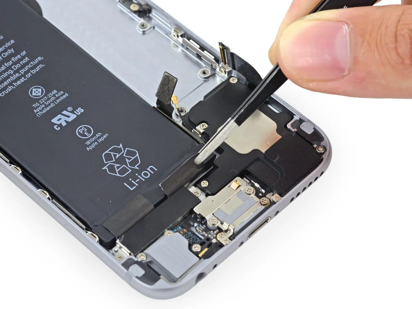
Exercise caution and avoid using sharp tools; accidental contact with the battery presents a fire hazard and potential release of hazardous materials.
Step 39
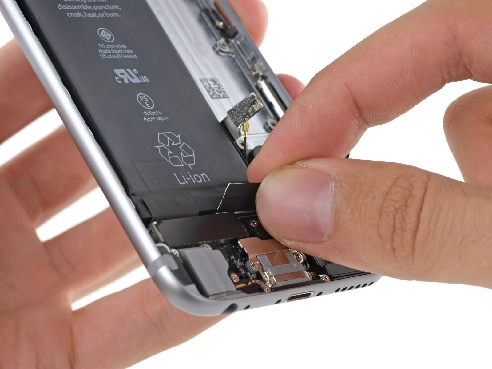
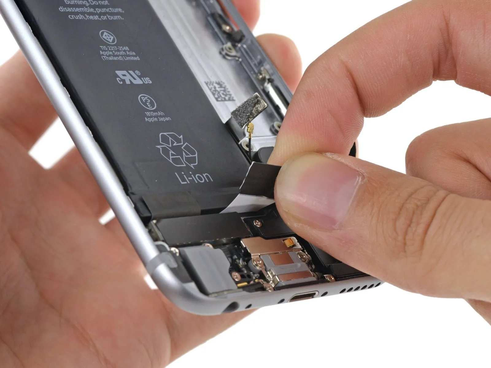
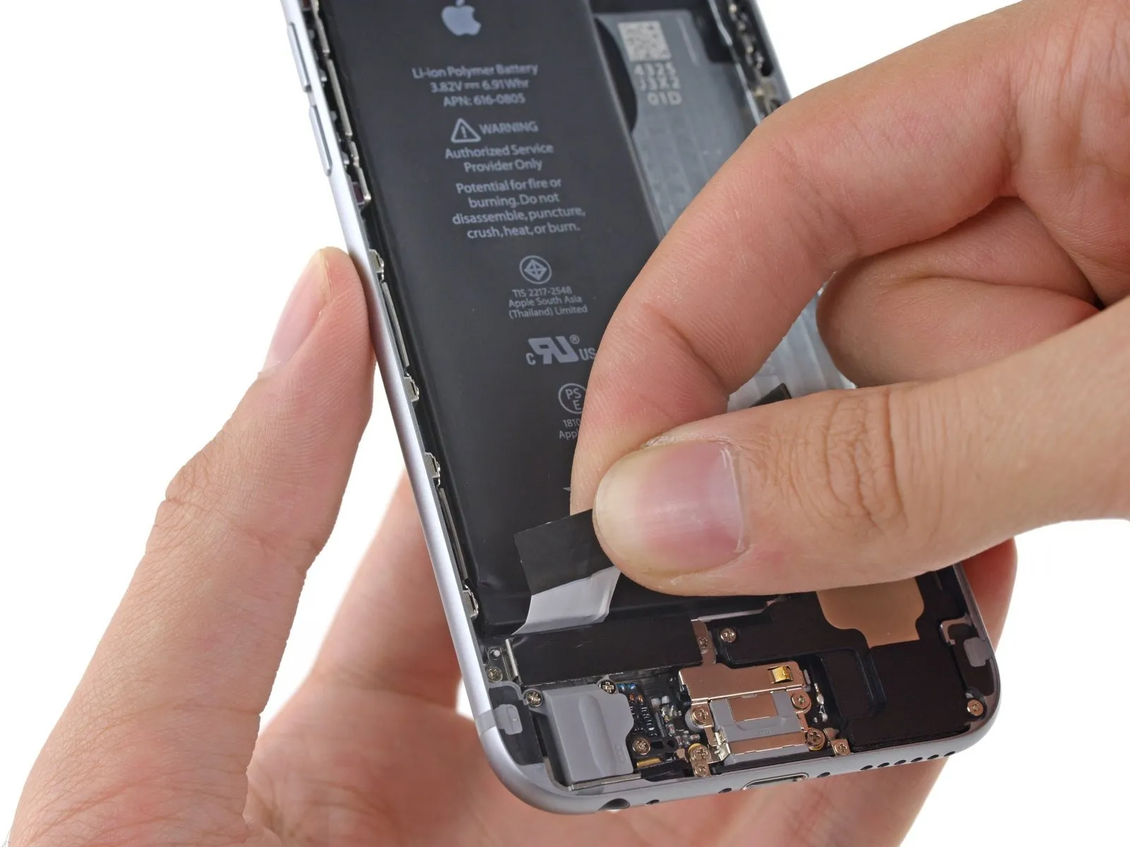
Carefully detach the battery's adhesive strip by drawing it downwards, in the direction of the iPhone’s base.
To prevent damage to the adhesive strip, avoid applying force in opposition to the battery or any of the lower-mounted parts.
Maintain a gentle, steady traction on the strip, permitting it to gradually disengage from the space between the battery and the rear case; halt the pulling action if you encounter greater friction and proceed to the subsequent instruction.
Should the battery adhesive strips detach while removing the battery, carefully gather any detached adhesive fragments with your fingers or a tool having a flat, non-piercing edge, and proceed with the removal.
Should a battery adhesive strip tear and become irretrievable during this process, discard the remaining strip and continue with Step 44.
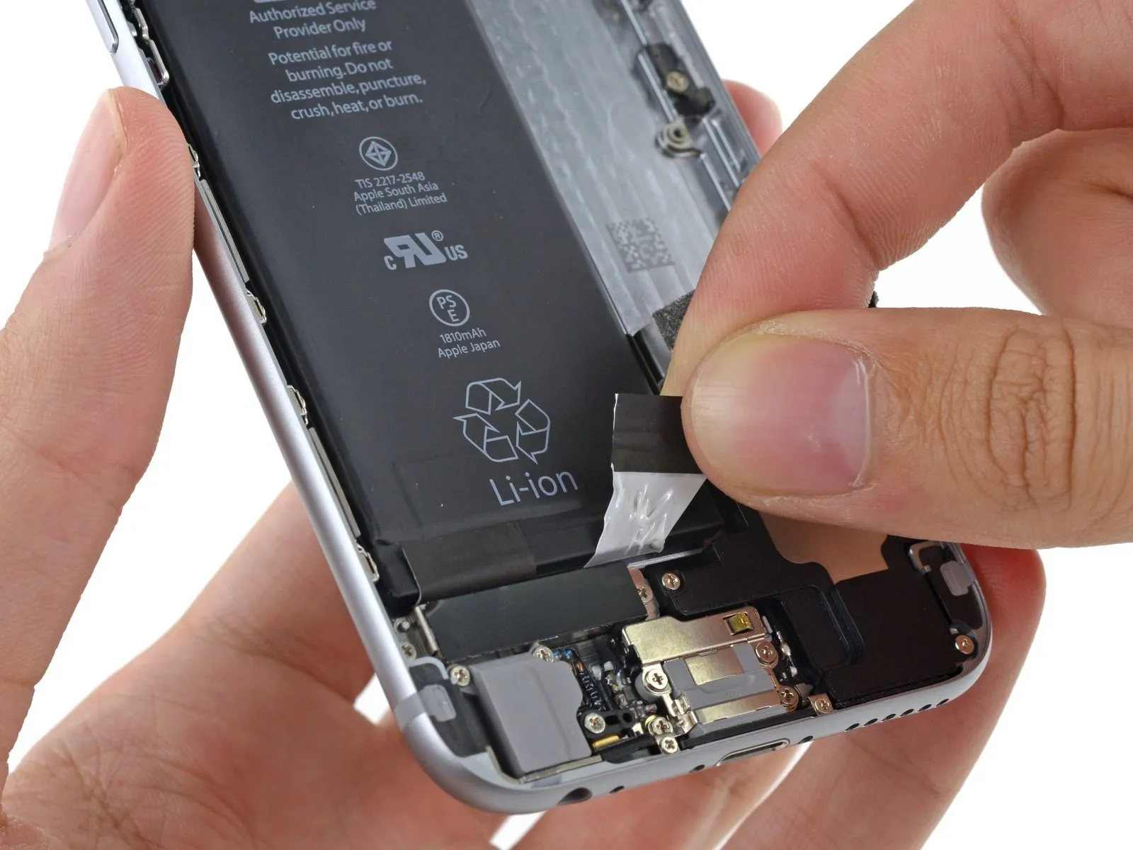
Step 40
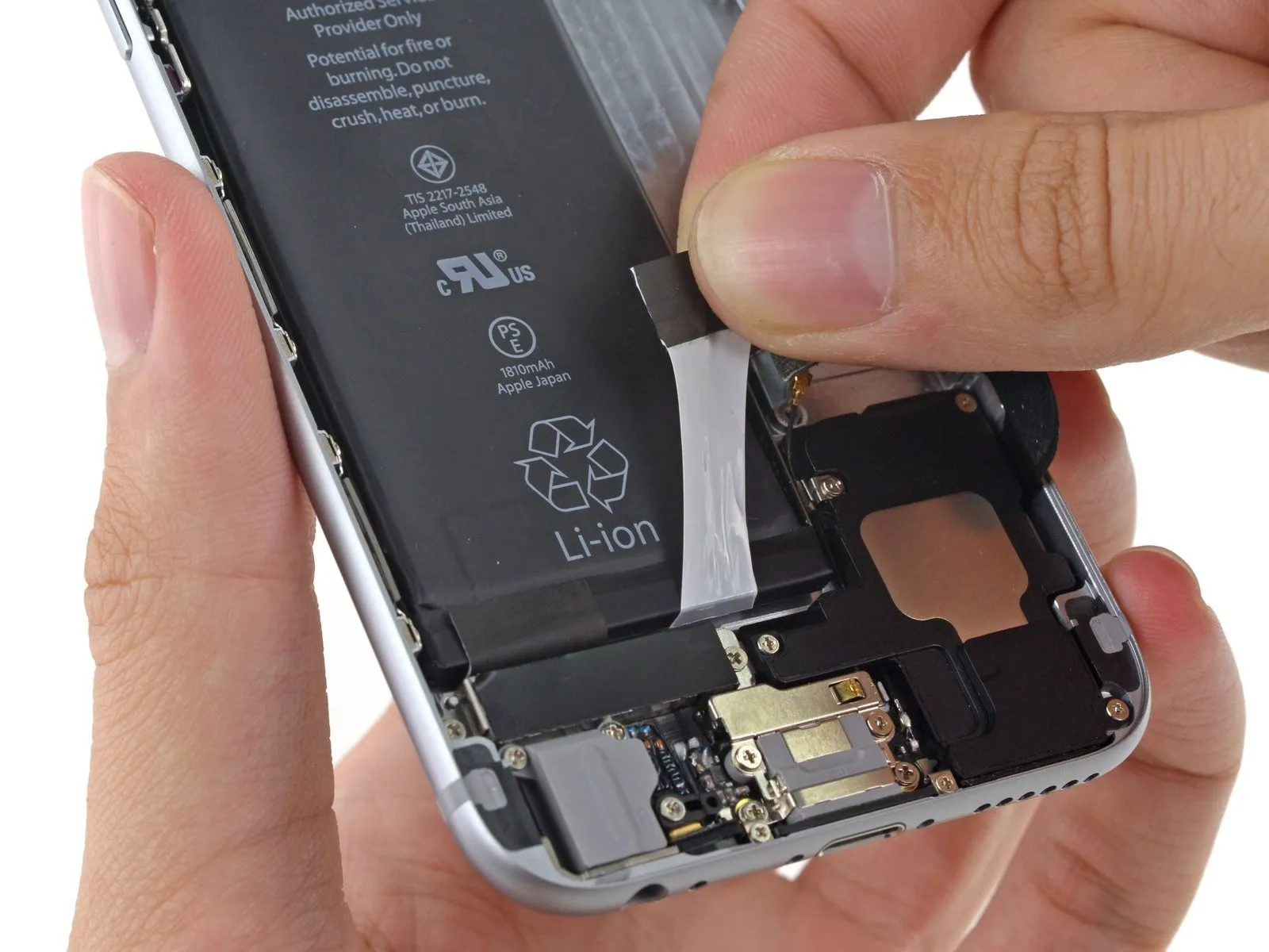
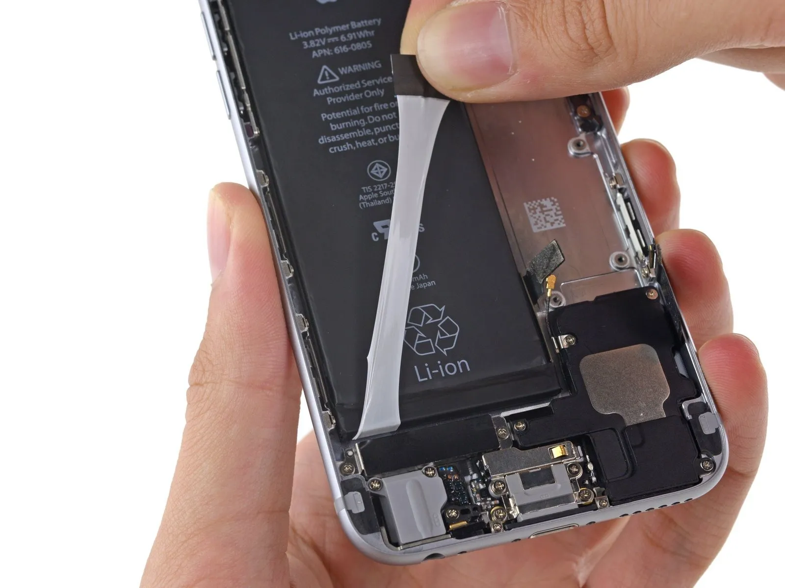
As you encounter greater difficulty moving the adhesive strip, carefully guide it along the battery's lower right edge.
Gently draw the adhesive tab vertically, moving it outward from the battery’s right side, permitting the adhesive strip to gradually disengage from the space between the battery and the iPhone’s rear enclosure, until the strip is fully detached.
To prevent damage, ensure the adhesive strip remains clear of the battery connector during installation.
Step 41

Using a 5/32-inch hex key, carefully tighten the four M4x8 pan head screws securing the fan assembly to the heatsink, ensuring a torque of 4 in-lbs is applied to each screw to prevent damage.
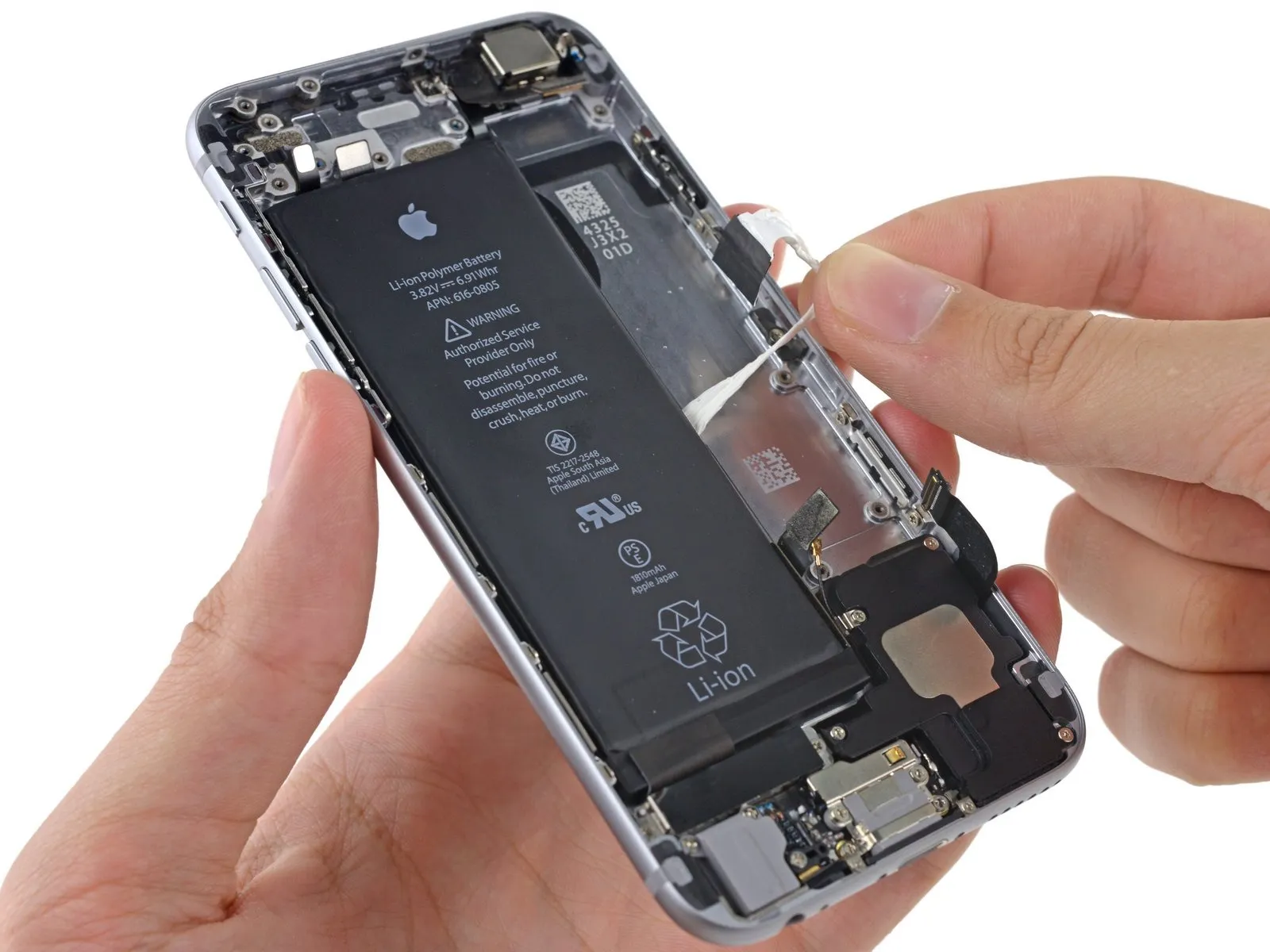
Carefully peel the adhesive strip on the battery's underside, starting from the lower left corner.
Carefully lift the battery's adhesive tab, separating it from the battery surface; the adhesive strip should then detach gradually from the space between the battery and the rear case.
Cease movement when you encounter a noticeable increase in opposing force.
Step 42
Using a 5/32-inch hex key, carefully tighten the four M4x8 socket head cap screws securing the fan shroud to the motor housing, ensuring a torque of 6 in-lbs to prevent damage.
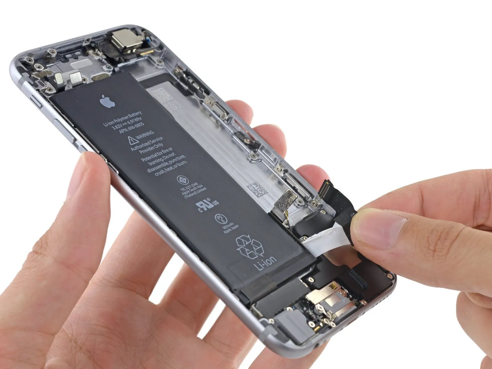
As you encounter greater difficulty moving the adhesive strip, carefully guide it along the battery's lower left edge.
To prevent damage, be careful not to catch the adhesive strip located on the battery's corner during handling.
Gently draw the adhesive tab vertically, moving it away from the left side of the battery, permitting the adhesive strip to gradually disengage from the space between the battery and the iPhone's rear enclosure until it is fully released.
Having completely detached the adhesive strips, proceed directly to Step 46, bypassing Steps 43 and 44.
Should the battery's adhesive strips become detached and inaccessible during the repair, continue with step 43.
Step 43
Using a 5/32-inch hex key, carefully tighten the four M4x8mm screws securing the fan assembly to the heatsink, ensuring a torque of 4.5 in-lbs to prevent damage.
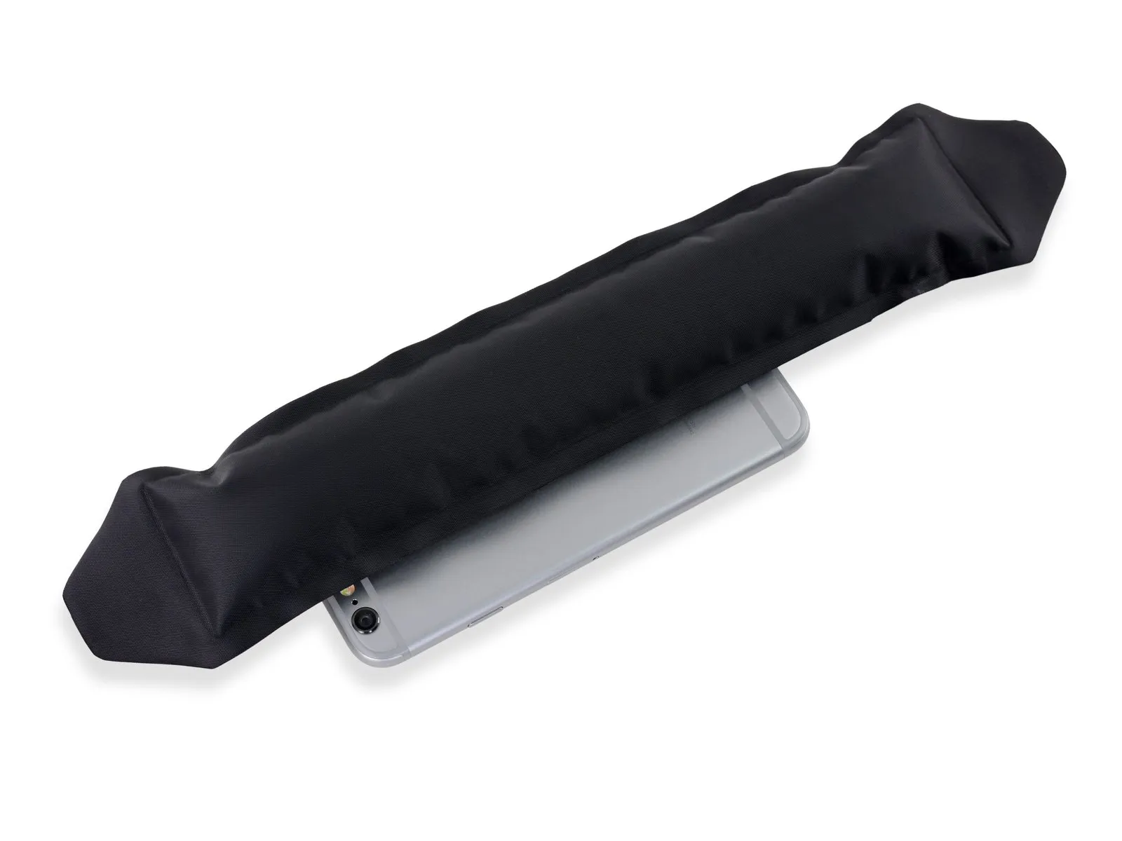
To free a battery adhered to the rear case after adhesive strip failure, apply heat using either an iOpener or a hair dryer, focusing the warmth on the rear case area immediately behind the battery.
To free a battery adhered to the rear case after adhesive strip failure, apply heat using either an iOpener or a hair dryer, focusing the warmth on the rear case area immediately behind the battery.
Step 44
Carefully align the 4mm diameter dowel pin with the corresponding hole in the chassis, ensuring it is fully seated before proceeding.
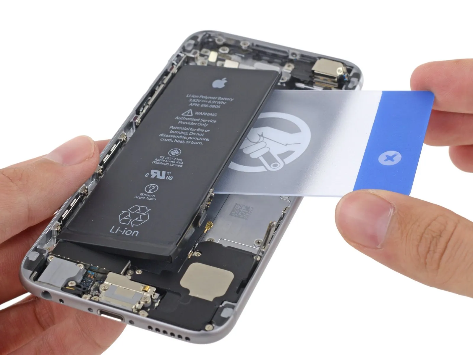
Using a plastic card, carefully slide it between the battery and the device's chassis, working along the battery's edge to reach the logic board.
To prevent battery damage and potential release of hazardous chemicals, maintain a perfectly level position for the card during handling.
Apply focused pressure across multiple areas of the card as needed to sever the adhesive bond securing the battery.
Step 45
Using a 5/32-inch hex key, carefully tighten the four M4x8 pan head screws securing the fan assembly to the heatsink, ensuring a torque of 4.5 in-lbs to prevent damage.
Following complete removal of all adhesive residue by peeling or prying, disconnect the iPhone's battery.
To ensure proper reattachment, use this guide to substitute fresh adhesive strips when putting the battery back in.
Following complete removal of all adhesive residue by peeling or prying, disconnect the iPhone's battery.
To ensure proper reattachment, use this guide to substitute fresh adhesive strips when putting the battery back in.
Step 46


Carefully detach the adhesive tape securing the screw on the upper left side of the rear camera assembly.
Step 47
Using a Phillips #00 screwdriver, detach the rear-facing camera bracket by unscrewing the included screws.
A screw with a 1.5-millimeter head diameter is required.
A screw with a 2.1-millimeter head diameter is required.
A screw with a 1.5-millimeter head diameter is required.
A screw with a 2.1-millimeter head diameter is required.
Step 48

Detach the bracket securing the rear camera assembly.
Step 49

Detach the antenna interconnect cable from the rear case, exercising caution.
Step 50

Carefully detach the rear camera assembly from the iPhone.
Step 51

Using a Phillips #00 screwdriver, detach the flash bracket by unscrewing the 1.2 mm screw that holds it in place.
Step 52
Detach the flash bracket, a component affixed to the rear case.
Step 53
Using a Phillips #00 screwdriver, detach the two screws, each measuring 2.2 mm, that secure the power button bracket.
Step 54


Carefully leverage the flash and microphone assemblies upward from their openings in the rear case using a spudger's tip, applying gentle pressure.
To remove parts bonded with strong adhesive, gently lift them away from the back cover using tweezers.
To remove parts bonded with strong adhesive, gently lift them away from the back cover using tweezers.
Step 55

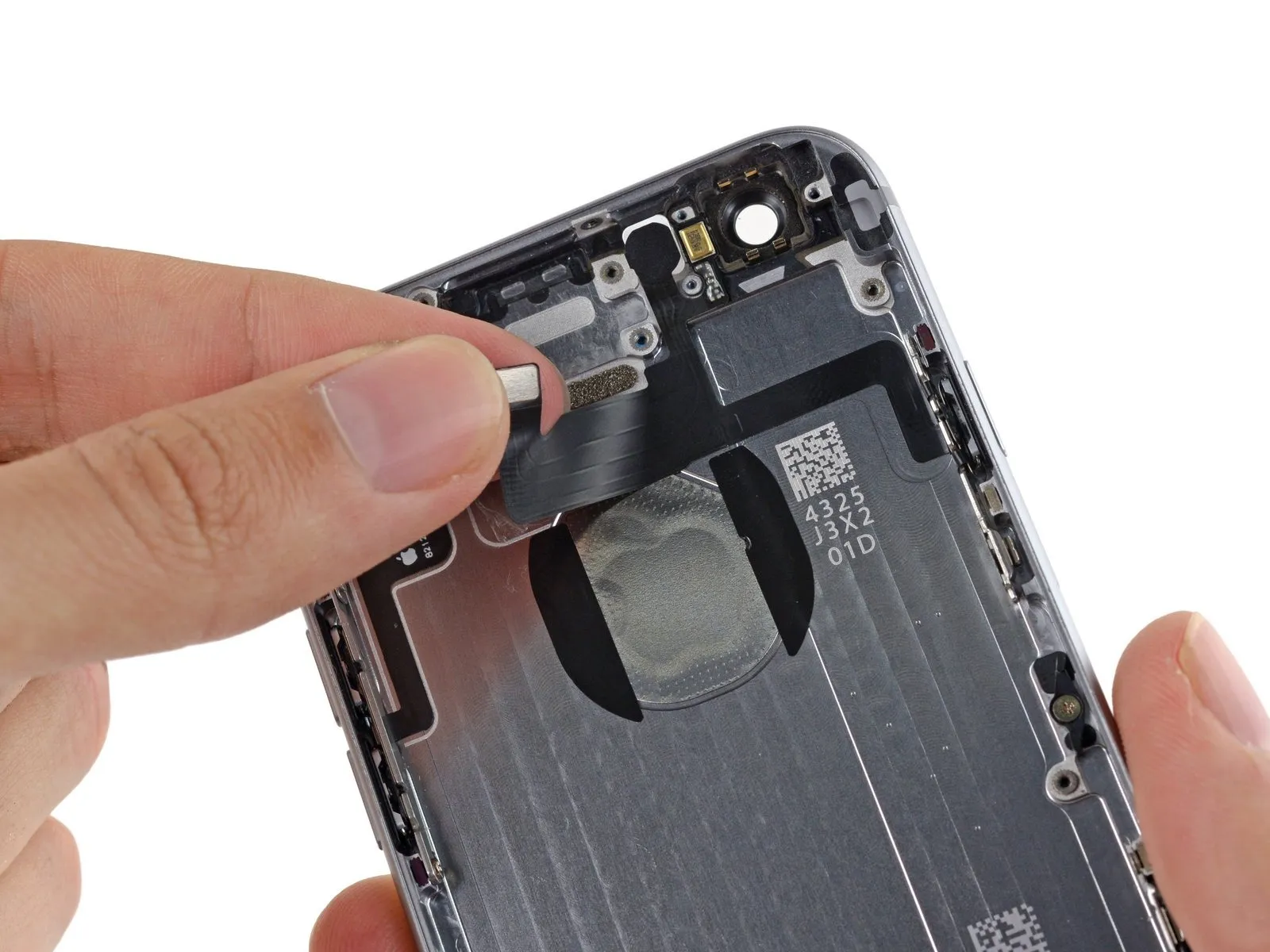
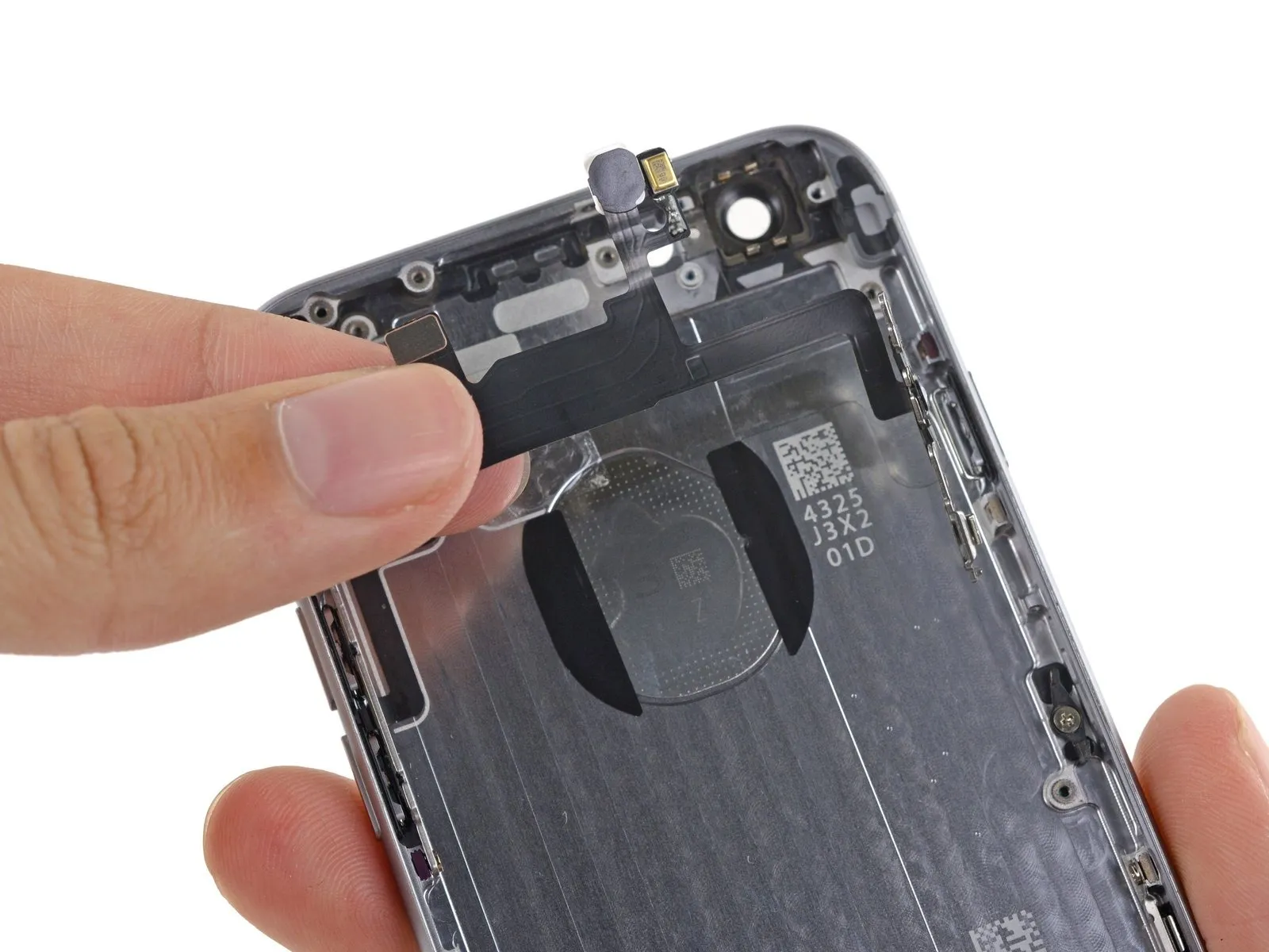
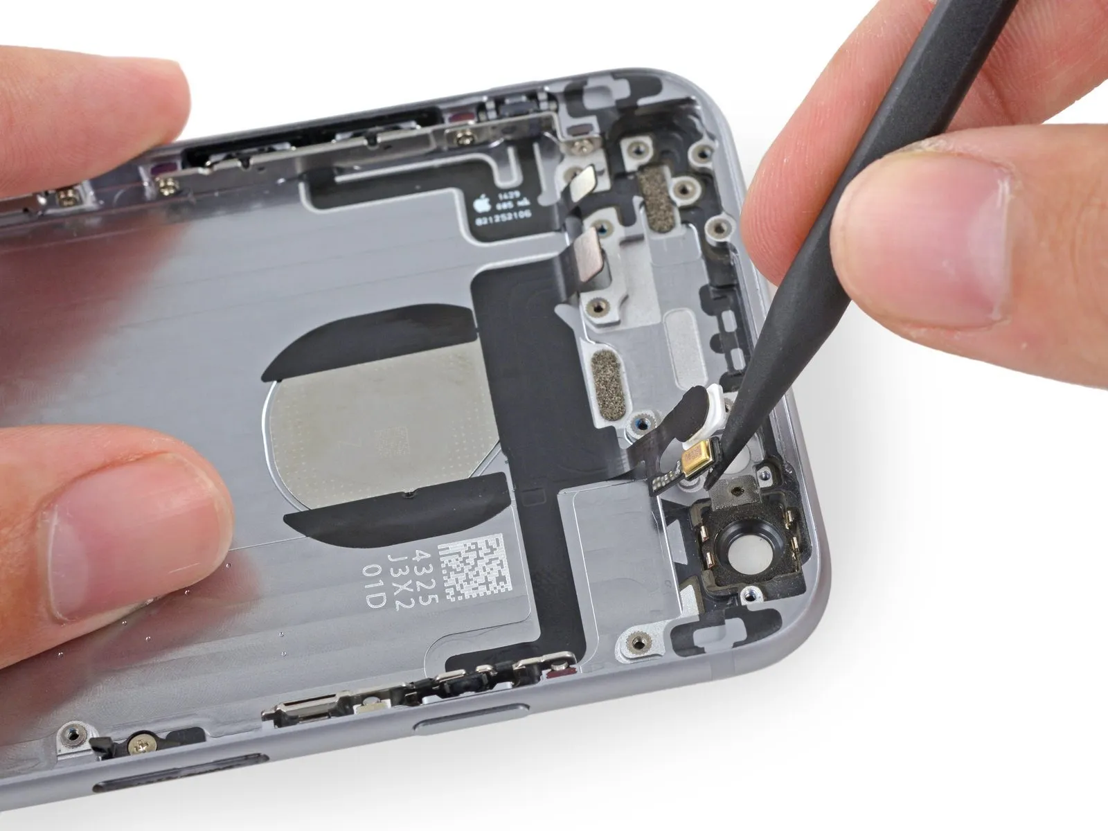
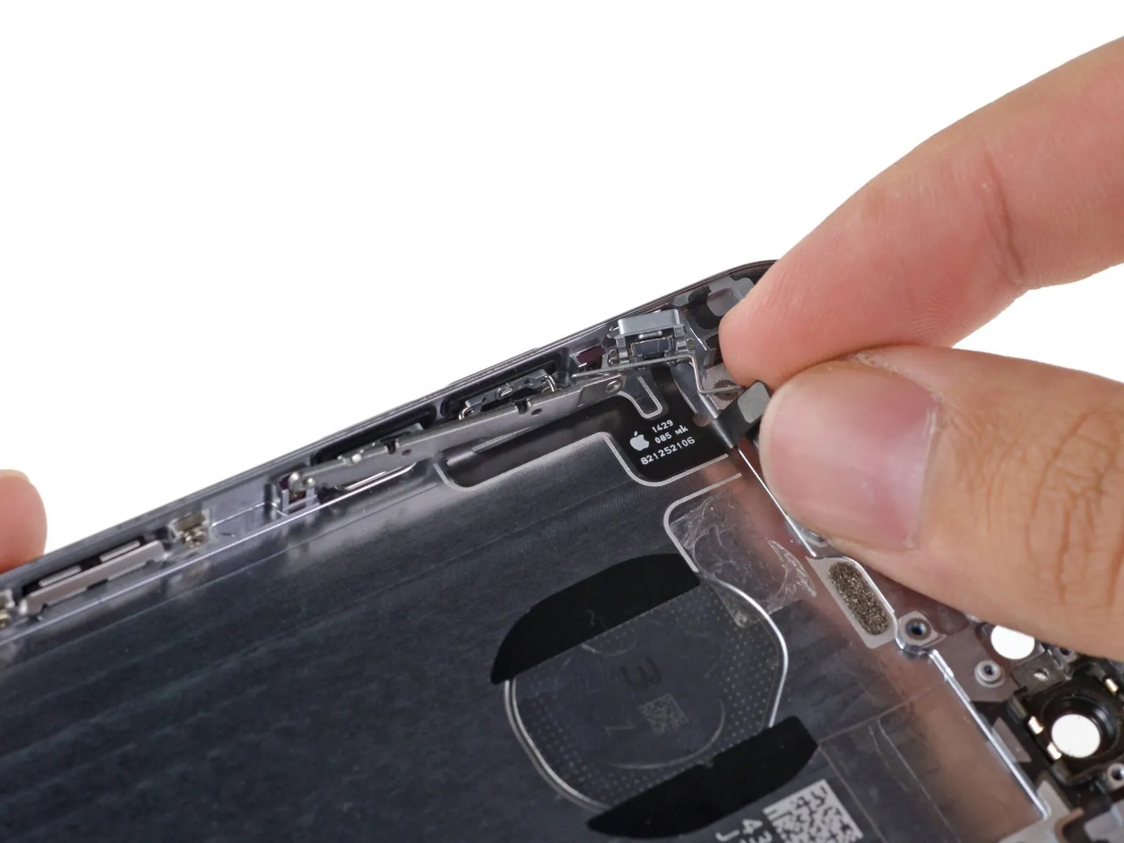
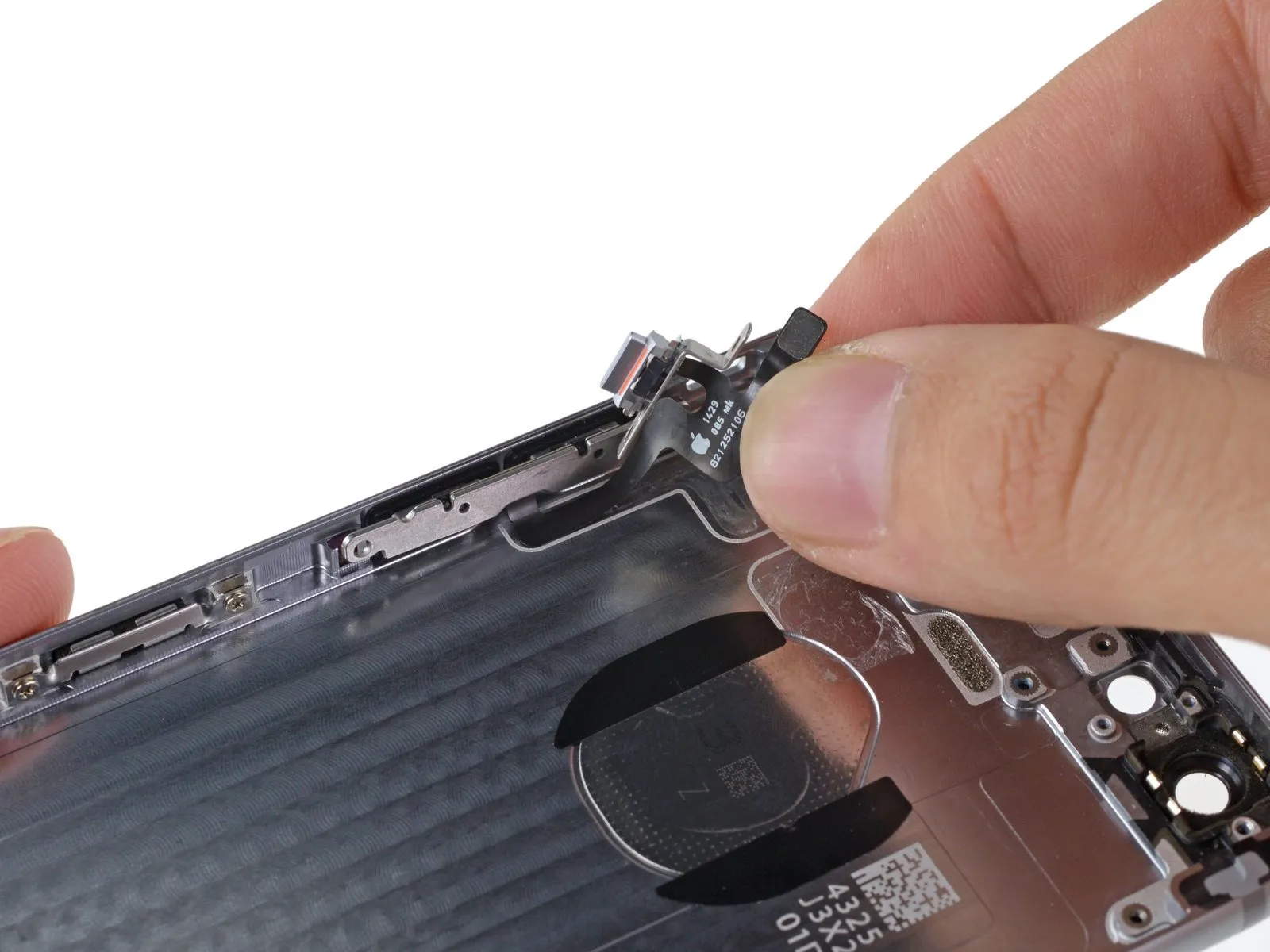
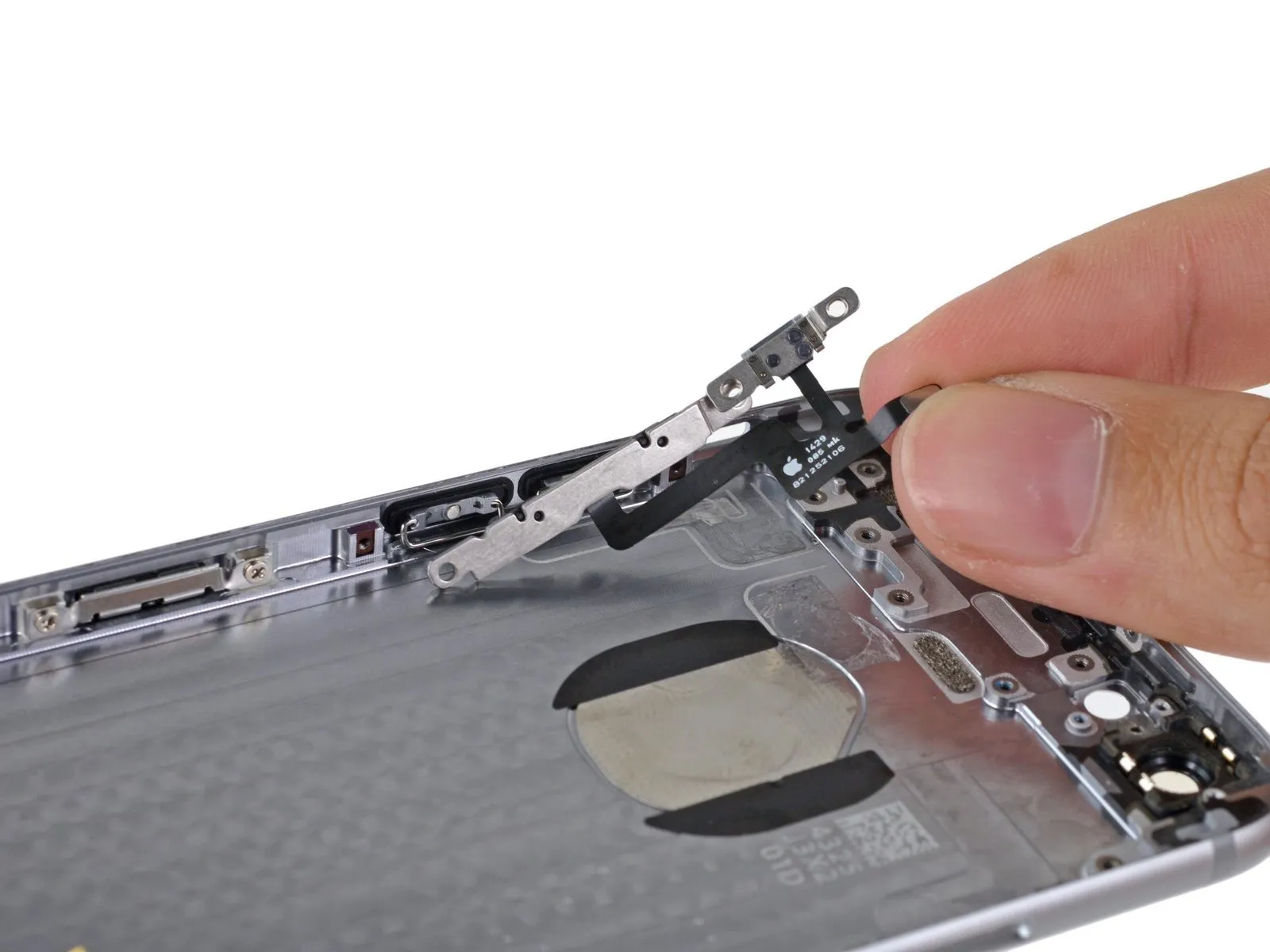
Carefully lift the flash, microphone, and power button assembly's cable from the back of the device housing, initiating the process at the connector.
Carefully remove the cable's outer jacket, paying close attention to the delicate, smaller terminations at each end.
Disconnect the cable linking the flash, microphone, and power button assembly to the device.
Carefully remove the cable's outer jacket, paying close attention to the delicate, smaller terminations at each end.
Disconnect the cable linking the flash, microphone, and power button assembly to the device.
Step 56 | Power Button
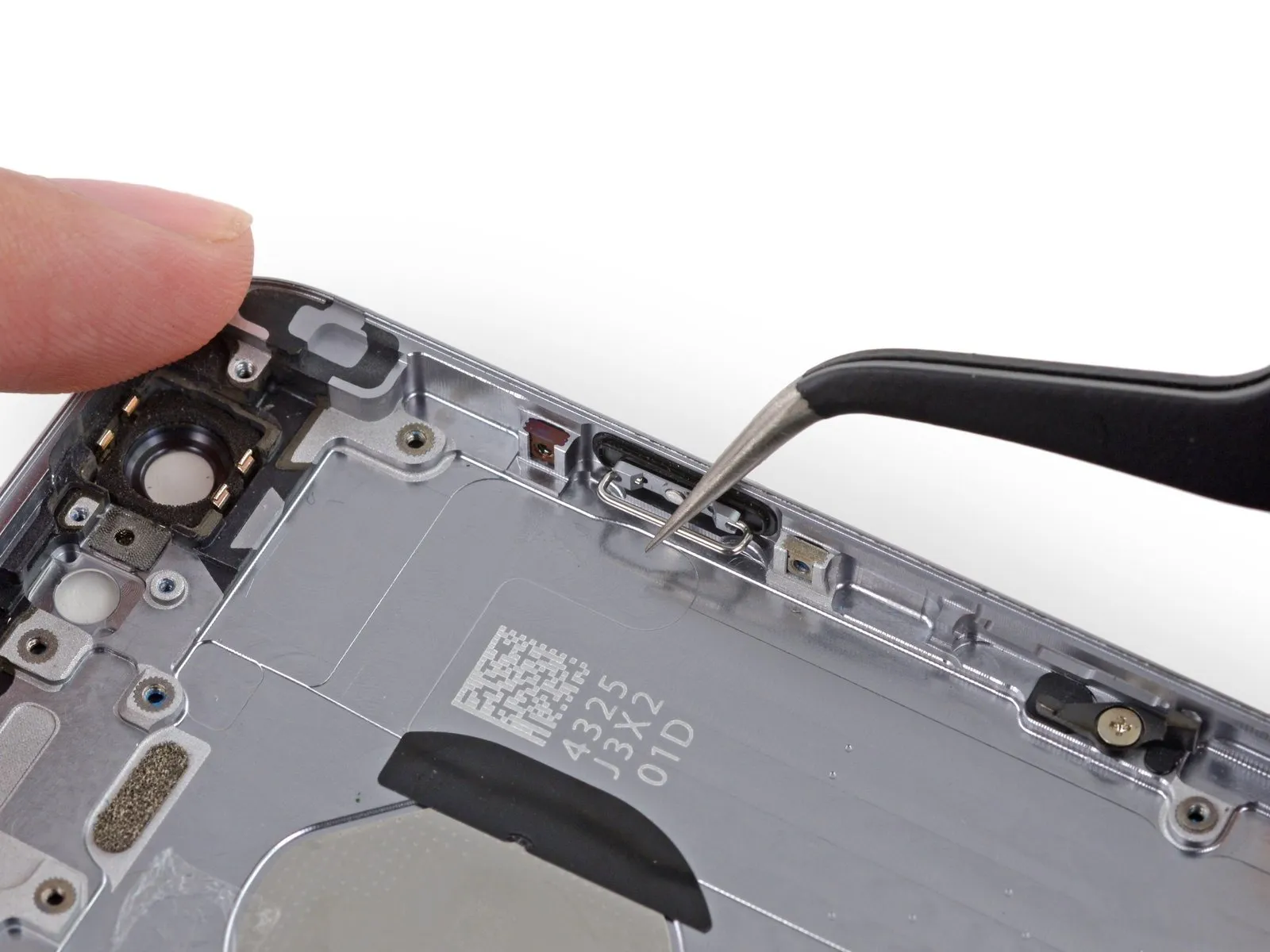
Carefully detach the power button from the back cover by grasping the metal portion and applying a pulling force.
To detach the power button, gently separate it from the case housing, being mindful of the adhesive gasket to avoid damaging the underlying membrane.
To detach the power button, gently separate it from the case housing, being mindful of the adhesive gasket to avoid damaging the underlying membrane.
Step 57 | Rear Case
Using a Phillips #00 screwdriver, detach the screws securing the volume control cable brackets.
Use two screws, each measuring 2.3 millimeters.
A screw with a diameter of 1.8 millimeters is required.
Use two screws, each measuring 2.3 millimeters.
A screw with a diameter of 1.8 millimeters is required.
Step 58
To gain access to the button covers, detach the brackets securing the hold switch and volume control button from the rear case.
Step 59
Carefully lift the volume control button cable from the back of the device housing, beginning at the connector.
Exercise caution and avoid forceful movements while lifting the delicate cable sections away from the enclosure.
Disconnect the cable connecting the volume control button to the rear case.
Exercise caution and avoid forceful movements while lifting the delicate cable sections away from the enclosure.
Disconnect the cable connecting the volume control button to the rear case.
Step 60


Using a gentle pulling motion, disengage the volume control buttons from the rear case by gripping the metal bar extending between them.
To detach the buttons, gently separate them from the case, being mindful of the adhesive gasket securing them; avoid forceful pulling that could tear the membrane.
To detach the buttons, gently separate them from the case, being mindful of the adhesive gasket securing them; avoid forceful pulling that could tear the membrane.
Step 61
- Using a Phillips #00 screwdriver, detach the speaker by unscrewing the four screws that hold it in place.
Use two screws, each measuring 2.9 millimeters.
Use two screws, each measuring 2.3 millimeters.
Step 62
- Carefully disengage the antenna interconnect cable clip from the speaker housing by applying pressure with a spudger tip.
Step 63


- Gently lift the speaker upwards while simultaneously sliding it away from the rear case.
Step 64
- Using a Phillips #00 screwdriver, detach the vibrator from the rear case by unscrewing the two screws, each measuring 1.6 mm.
Step 65

- Carefully detach the iPhone's vibrator component.
Step 66
Using a Phillips #00 screwdriver, detach the Lightning port retaining bracket by unscrewing the two 3.1 mm screws that hold it in place.
Step 67

Using a 2.5mm hex wrench, detach the bracket securing the Lightning port.
Step 68
Using a Phillips #00 screwdriver, detach the 3.6 mm shoulder screw securing the microphone brace.
Step 69
Detach the microphone support structure from the iPhone.
Step 70
Using a Phillips #00 screwdriver, detach the six screws securing the Lightning connector cable assembly.
Use two shoulder screws, each with a 3.1 mm diameter.
Use two screws, each measuring 1.7 millimeters.
Use two screws, each measuring 1.5 mm.
Use two shoulder screws, each with a 3.1 mm diameter.
Use two screws, each measuring 1.7 millimeters.
Use two screws, each measuring 1.5 mm.
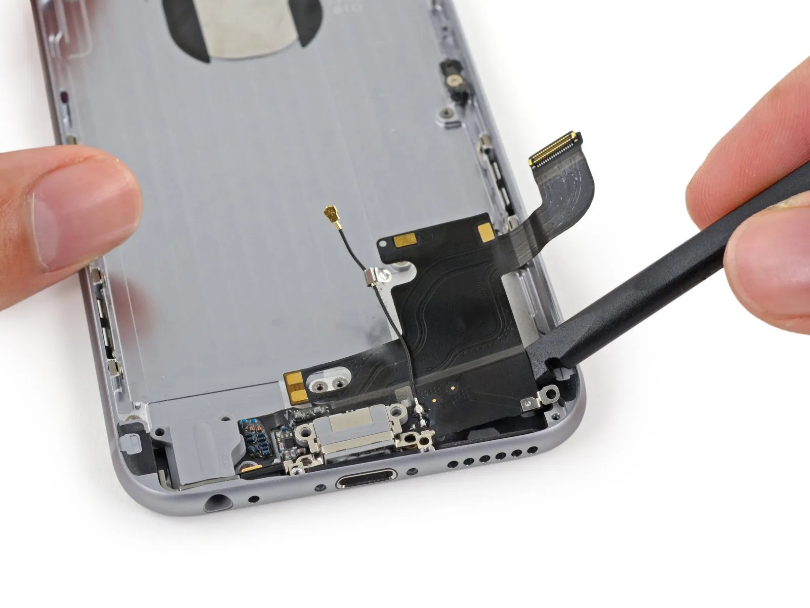
Step 71


Carefully lift the Lightning connector cable assembly away from the rear case's underside, employing the flat spudger tip to initiate the separation.
Step 72

Gently lift the Lightning connector cable assembly a small amount, ensuring it disengages from the screw posts securing the vibrator and speaker.
Step 73
Employ the flat spudger tip to gently pry up the cable assembly's Lightning connector area, releasing the securing adhesive.
Step 74
Carefully leverage the microphone component of the Lightning cable assembly from its molded position within the rear case using a spudger tip.
Step 75
Using a spudger, carefully disengage any remaining adhesive securing the cable assembly connecting the Lightning connector to the headphone jack.
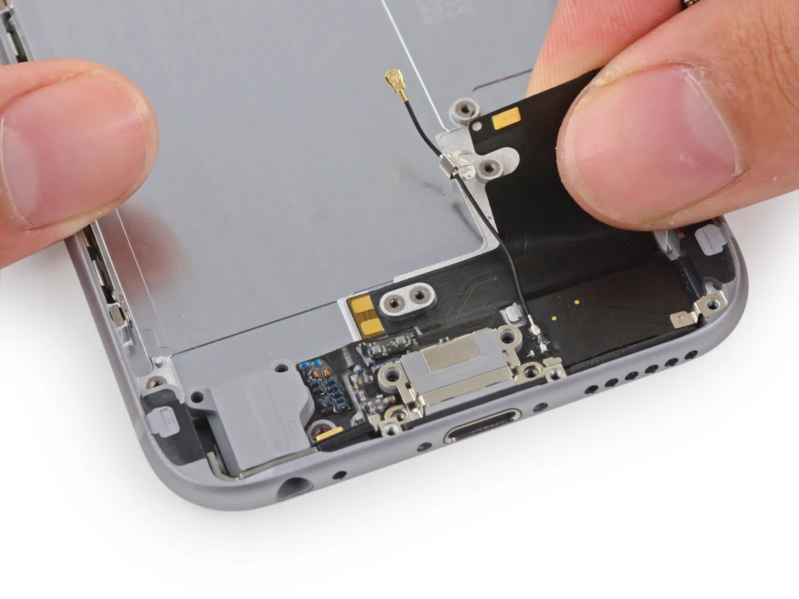
Step 76
Carefully employ the pointed end of a spudger to gently dislodge the headphone jack from its opening in the back housing.
Carefully detach the Lightning connector cable assembly from the iPhone.
Carefully detach the Lightning connector cable assembly from the iPhone.
Step 77
Using a Phillips #00 screwdriver, detach the SIM eject lever by unscrewing the single 1.7 mm screw that holds it in place.
Step 78


Using a small, flathead screwdriver, carefully detach the SIM eject lever from the back cover.
Verify the new rear case has the identical components present as the original before proceeding with reassembly; any leftover parts from the original rear case must be moved to the replacement.
Verify the new rear case has the identical components present as the original before proceeding with reassembly; any leftover parts from the original rear case must be moved to the replacement.