iPhone 6 Teardown
Disassemble two iPhones simultaneously to expedite the repair process.
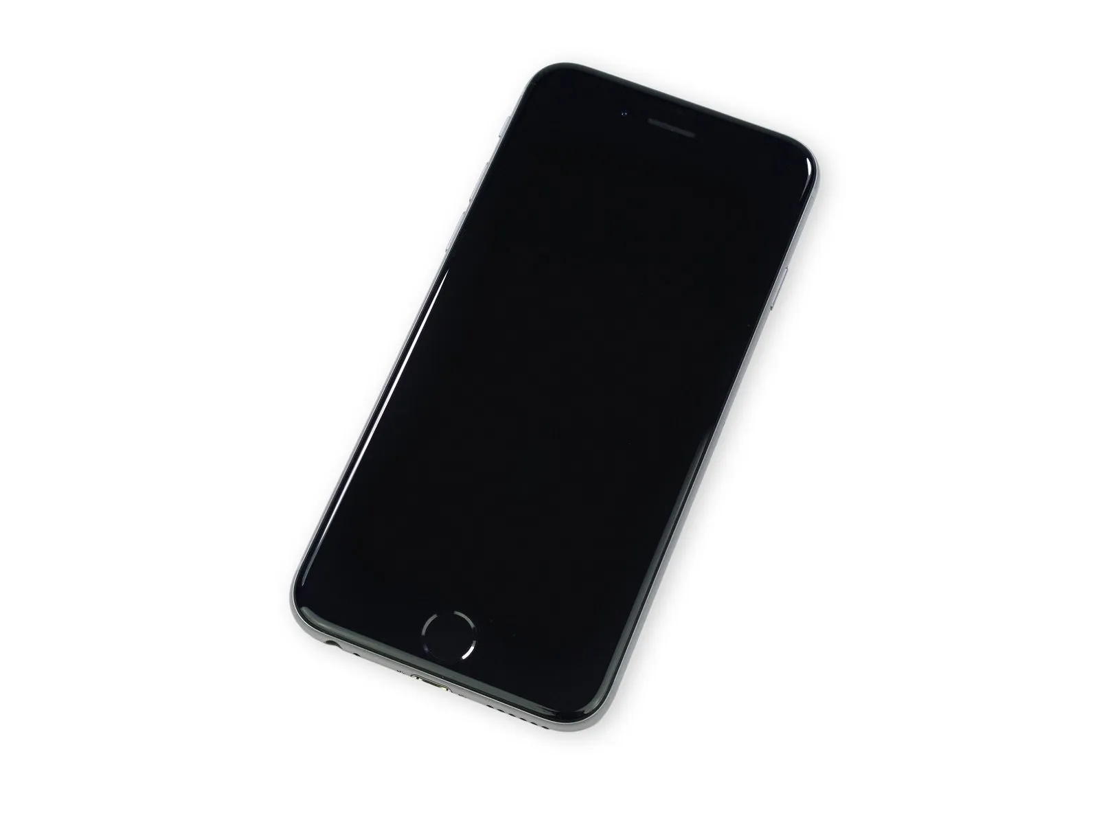
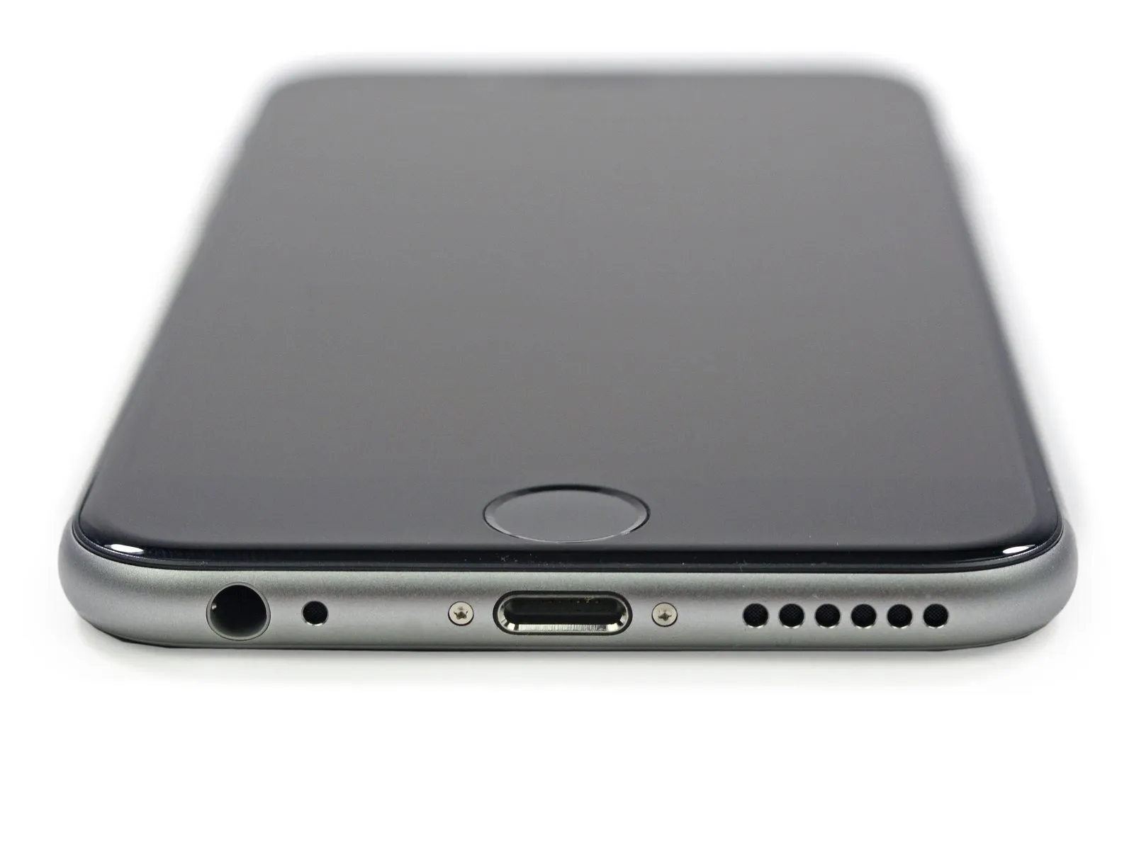
- After examining the iPhone 6 Plus, focus your attention to the iPhone 6, which, despite its 4.7-inch display, remains a large device within the iPhone lineup.
- Carefully place the device on the teardown table to reveal the unexpectedly large component that necessitated a departure from Apple’s standard design.
To view the iPhone 6 disassembly instructions in your preferred language—English, French, German, Spanish, Italian, Dutch, Russian, or Chinese—simply select the corresponding flag symbol.
Stay informed about future disassembly projects by connecting with us on Facebook, Instagram, or Twitter to receive updates.
Step 1 | iPhone 6 Teardown

Begin the iPhone 6 examination by reviewing its technical specifications.
- The device utilizes an Apple A8 processor featuring a 64-bit architecture.
- The motion coprocessor is an M8, second generation.
- The device offers storage options of 16 gigabytes, 64 gigabytes, or 128 gigabytes within its internal memory.
- The screen measures 4.7 inches diagonally and presents a resolution of 1334 by 750 pixels, resulting in a pixel density of 326 pixels per inch, characteristic of a Retina HD display.
- The device incorporates an 8-megapixel iSight camera, featuring 1.5-micrometer pixels and phase-detection autofocus capabilities, alongside a 1.2-megapixel FaceTime camera.
- The device incorporates a Touch ID fingerprint sensor for the home button, a barometer, a 3-axis gyro, an accelerometer, and an ambient light sensor.
- The device incorporates wireless capabilities including 802.11a, 802.11b, 802.11g, 802.11n, and 802.11ac Wi-Fi, Bluetooth version 4.0, NFC functionality, and support for 20 LTE bands.
Step 2


Having eagerly anticipated the release of the curved iPhone 6, many consumers experienced extended wait times to acquire the device.
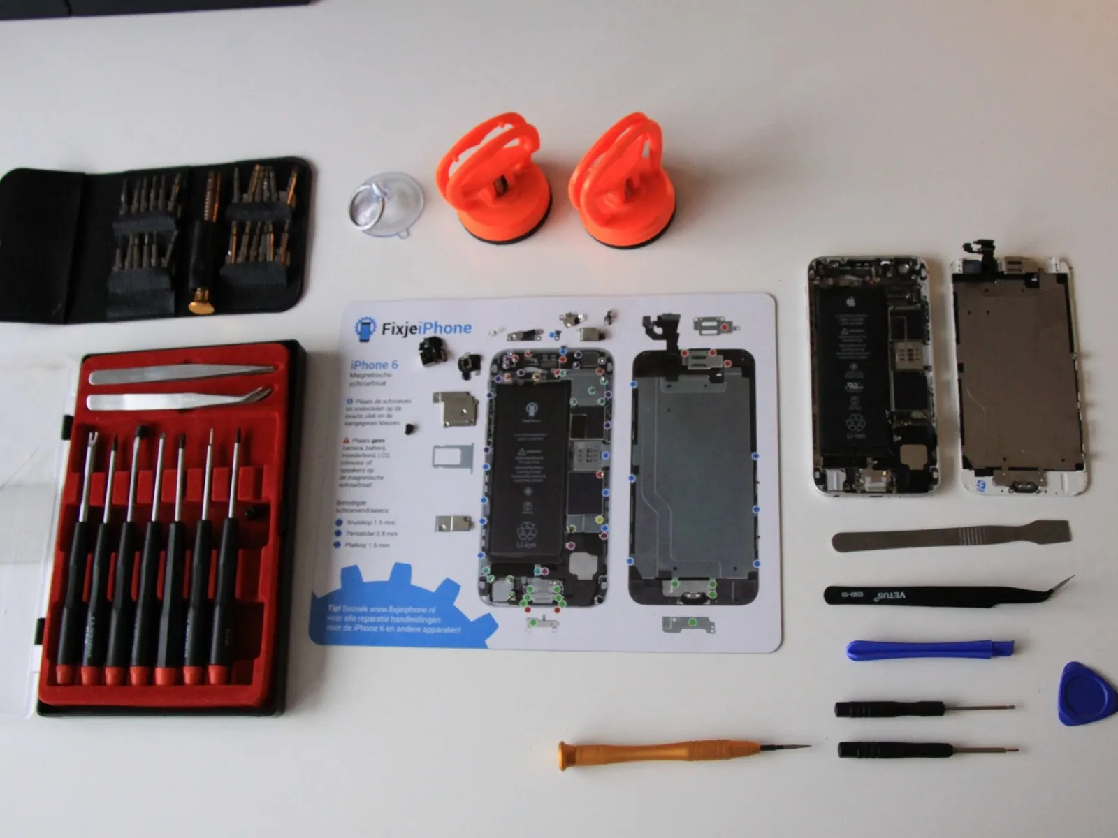
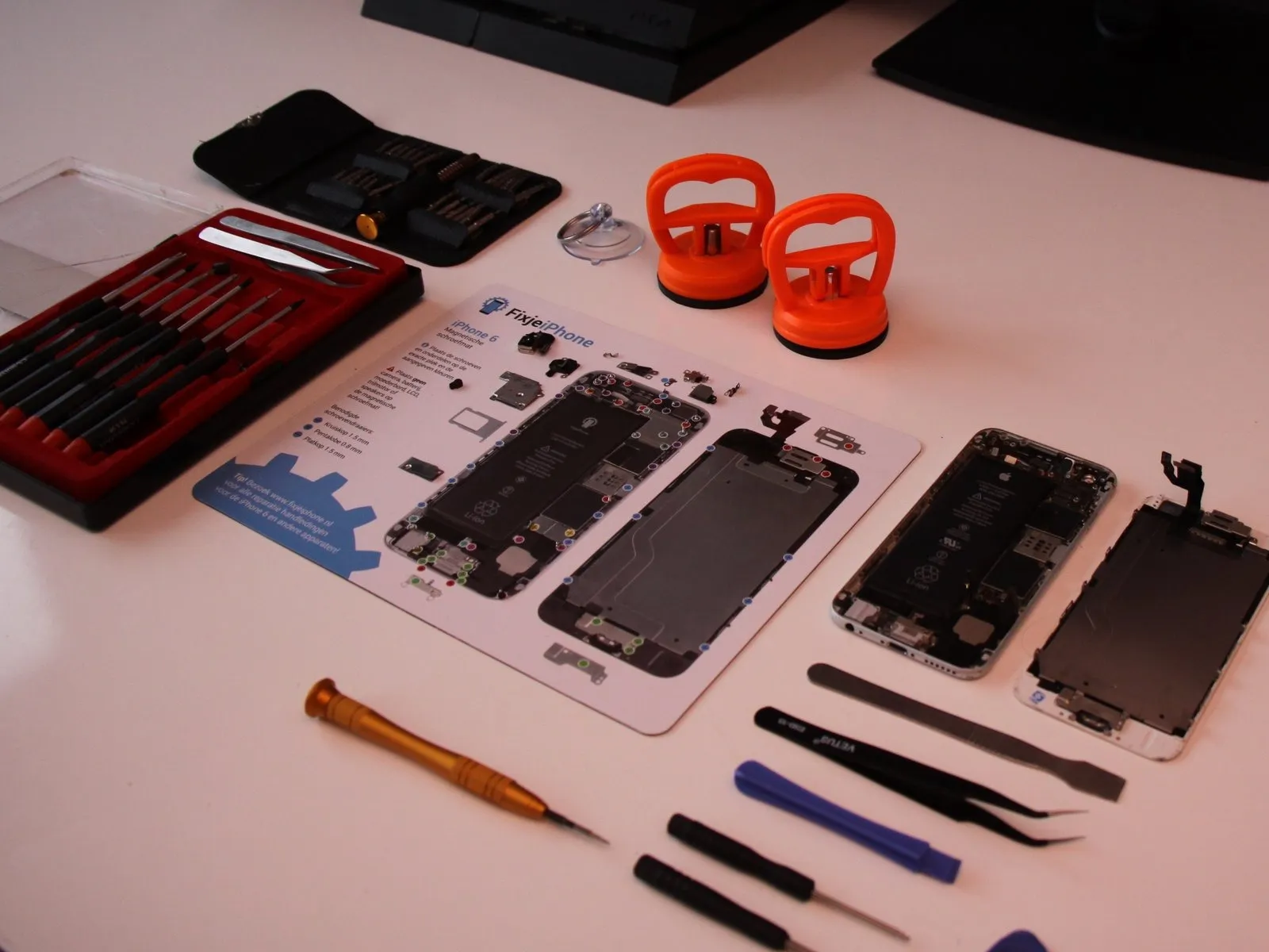
Our teardown benefited from the generosity of MacFixit Australia, who provided access to their Melbourne location; they offer Mac and iPhone upgrades, accessories, and iFixit toolkits.
Our teardown benefited from the generosity of MacFixit Australia, who provided access to their Melbourne location; they offer Mac and iPhone upgrades, accessories, and iFixit toolkits.
Step 3
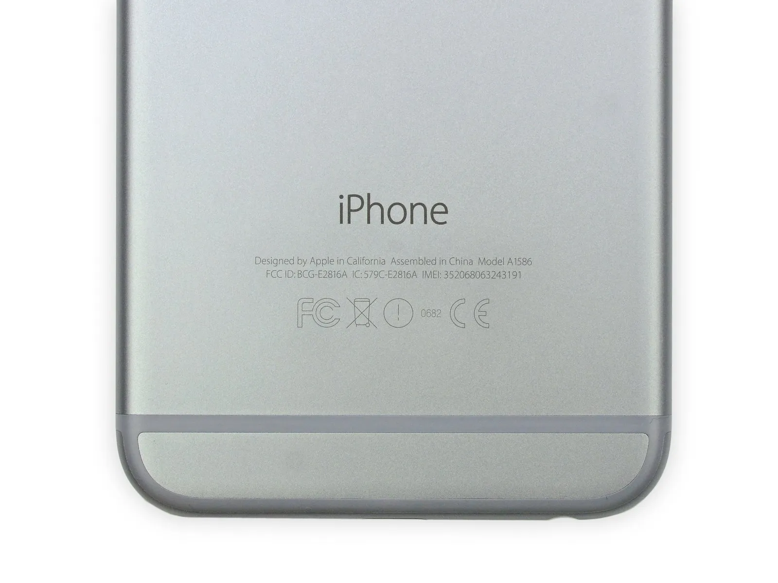
This specific iPhone 6 is identified by Apple as model number A1586.
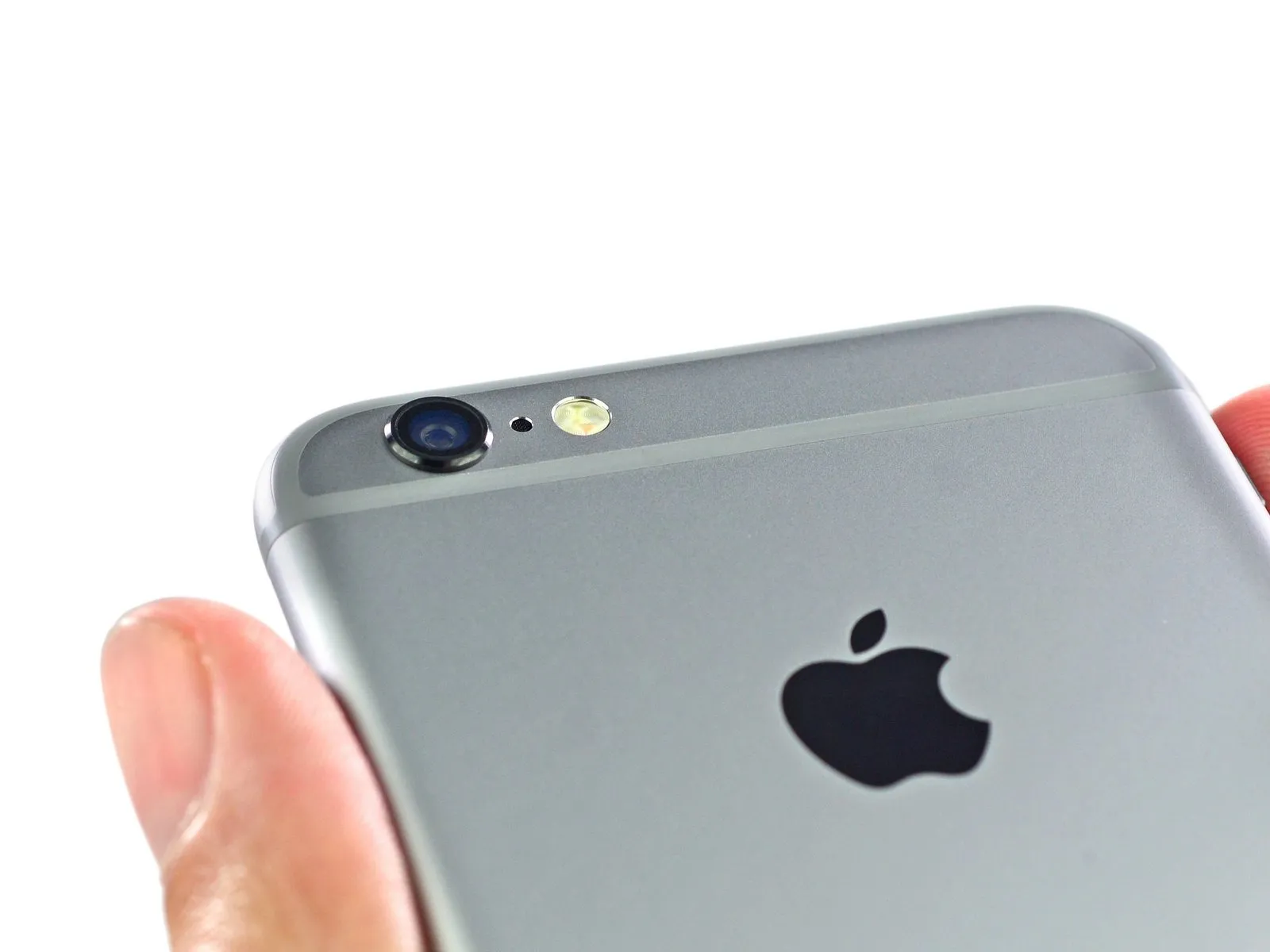
Due to Apple’s decision to prioritize enhanced optical performance, the iPhone 6’s rear lens assembly protrudes noticeably from the device's upper surface, creating the recognizable camera bump.
Using calipers, the measured protrusion is approximately 0.6 millimeters.
The optical components have been successfully reassembled and are functioning as intended.
Step 4
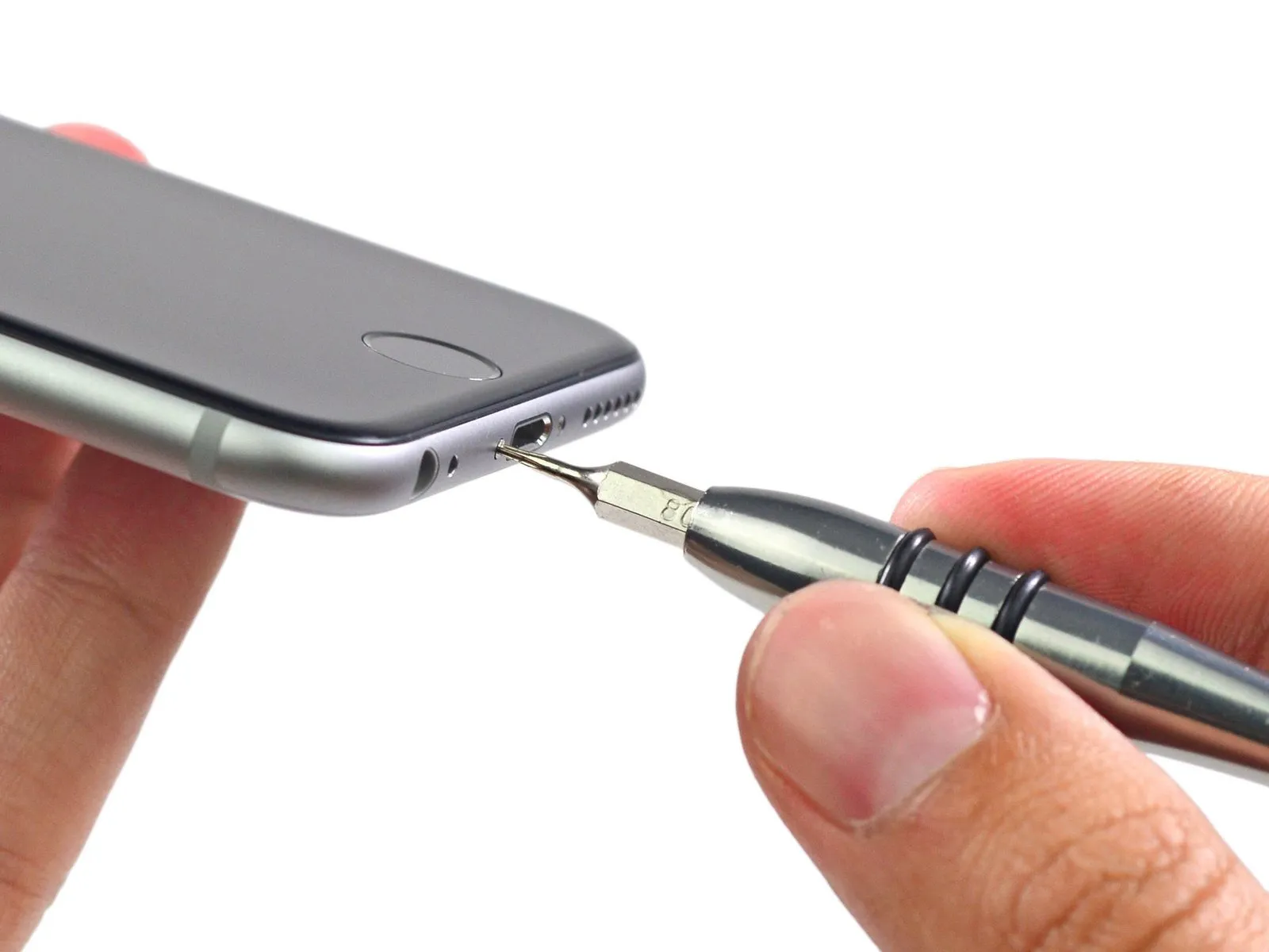
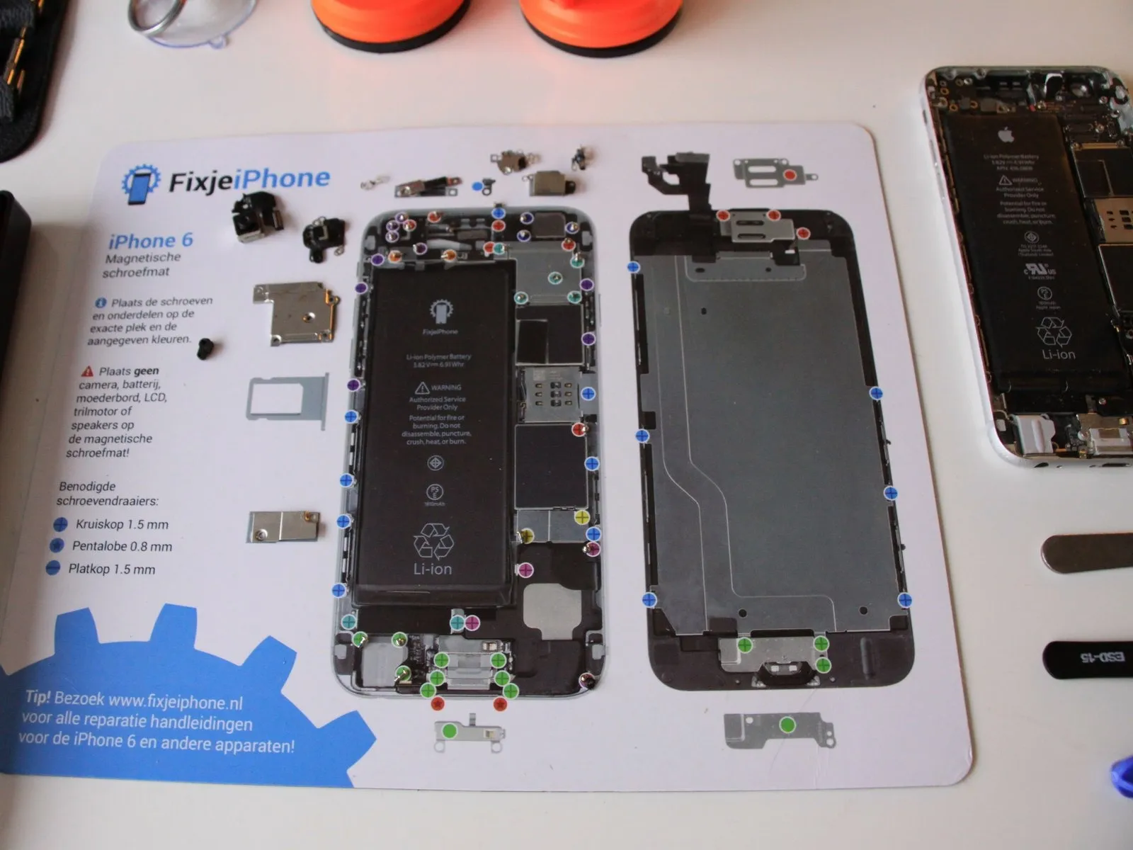
The iPhone 6's shape echoes the original iPhone's aesthetic, differing only in the absence of a Lightning connector and Pentalobe screws.
Using the provided 64 Bit Driver Kit, detach the Pentalobe screws securing the iPhone 6.
Despite our preference for standard fasteners, this iPhone model can be disassembled without needing to apply heat.
Using the provided 64 Bit Driver Kit, detach the Pentalobe screws securing the iPhone 6.
Despite our preference for standard fasteners, this iPhone model can be disassembled without needing to apply heat.
Step 5
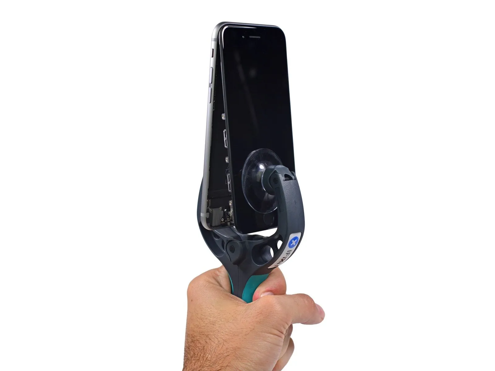
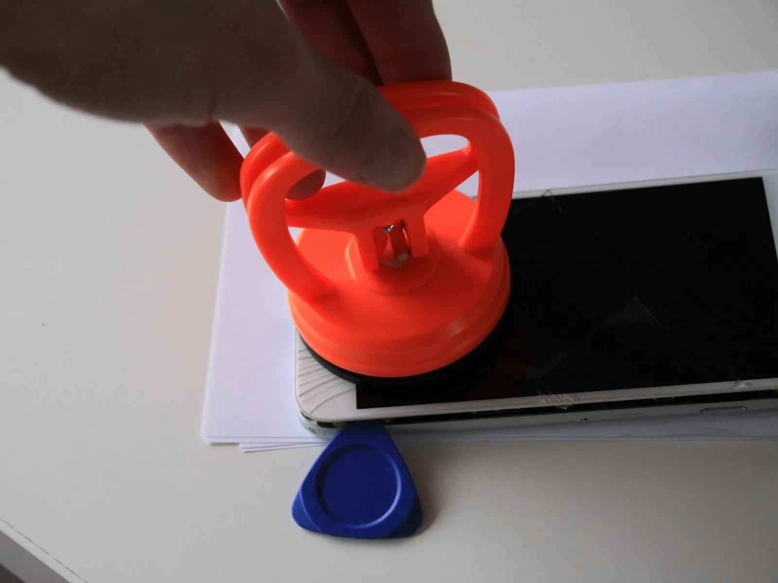
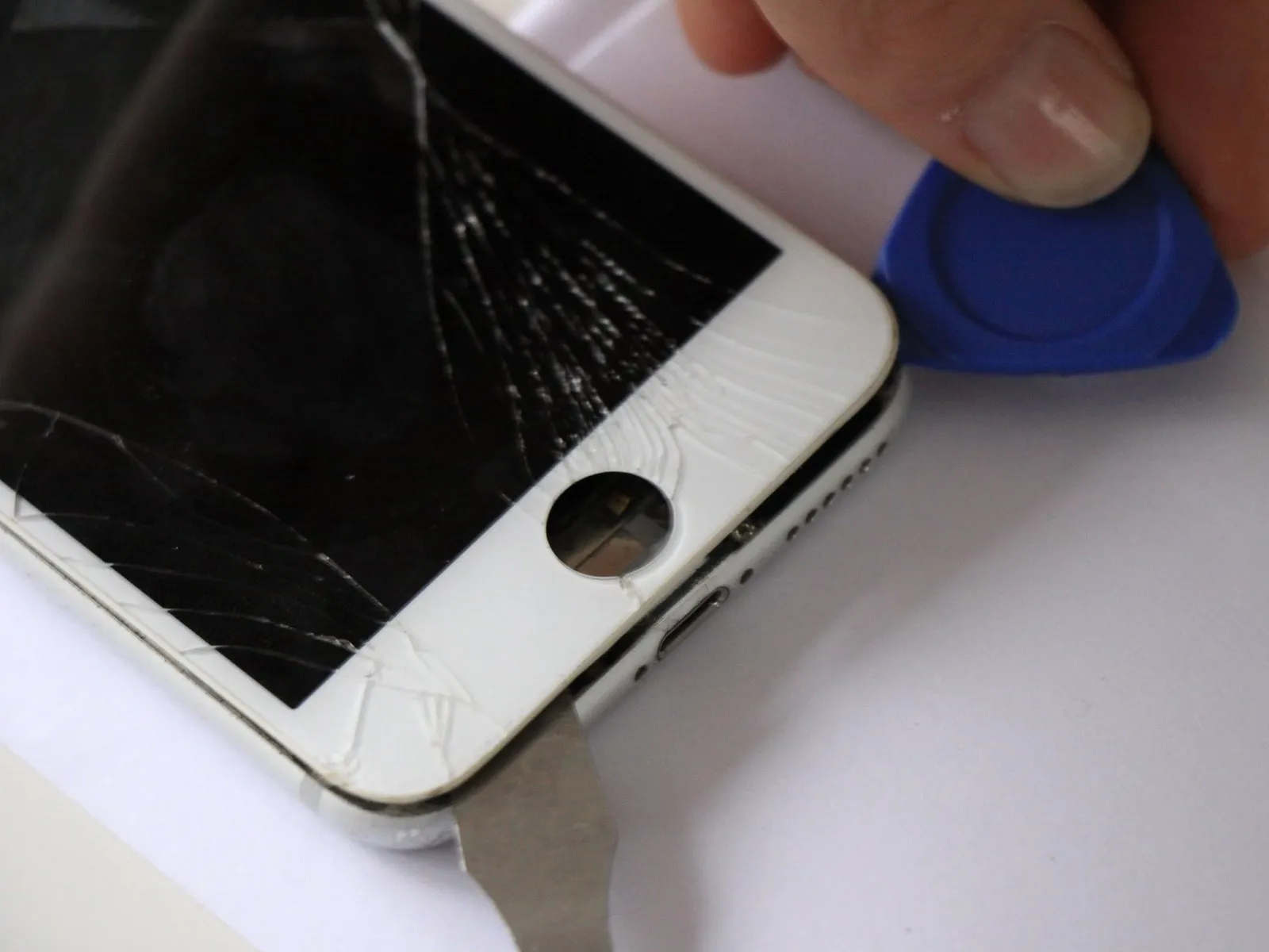
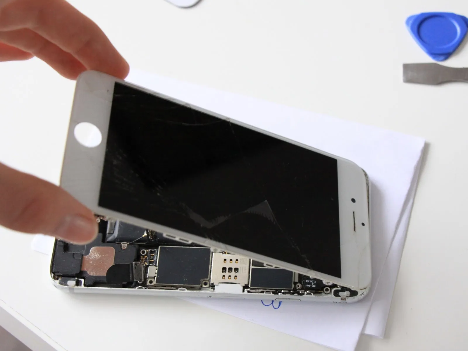
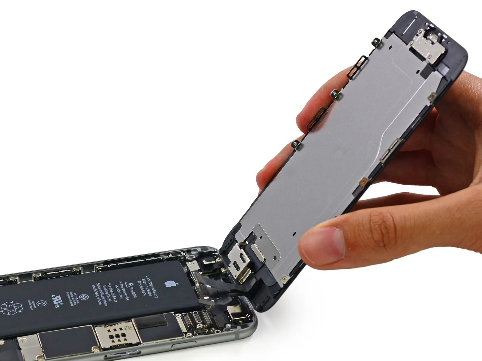
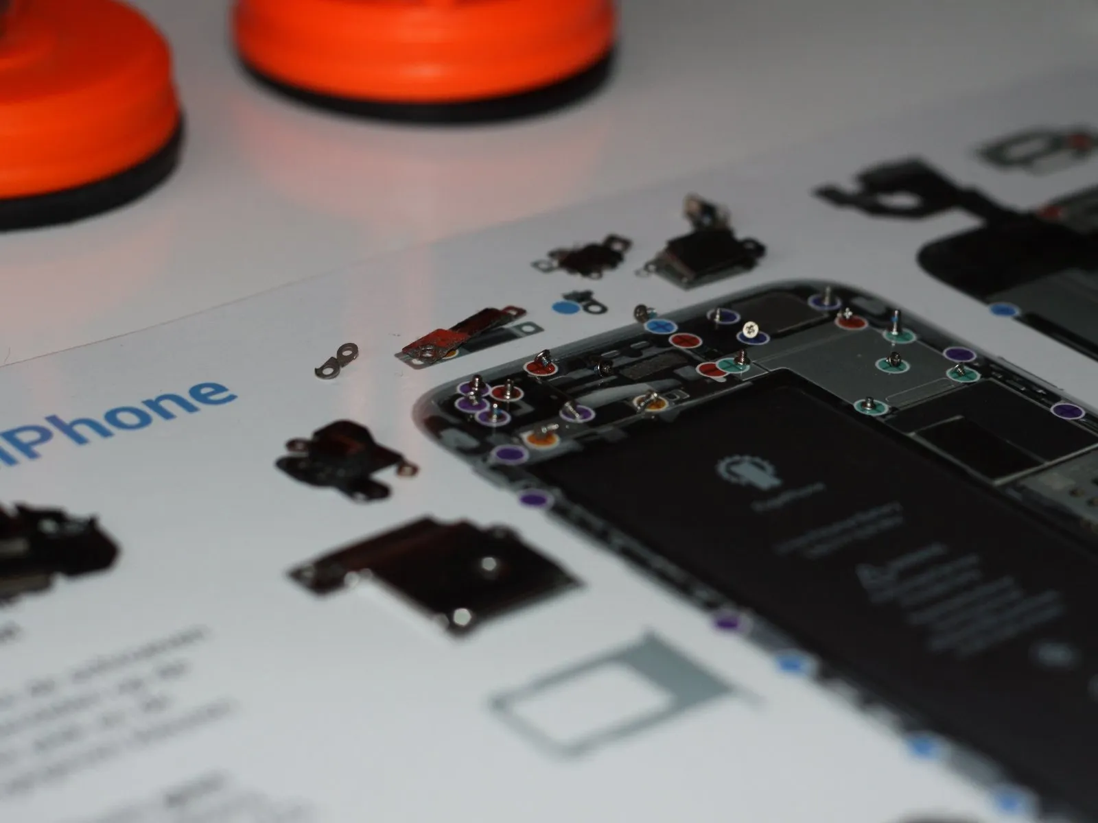
Employ the iSclack tool to separate the device housing, a technique known for its efficient and precise disassembly.
For secure handling during this procedure, it is recommended to maintain a two-handed grip on the iPhone, as it is susceptible to damage if dropped.
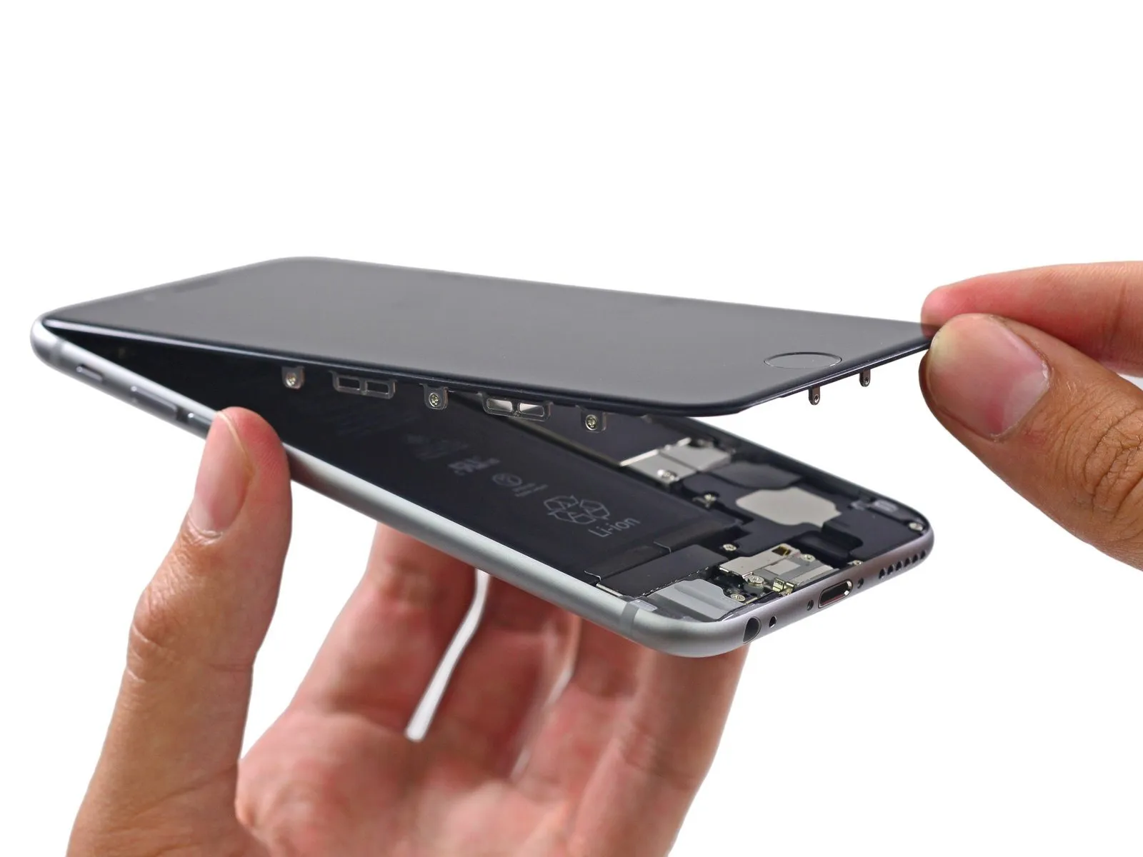
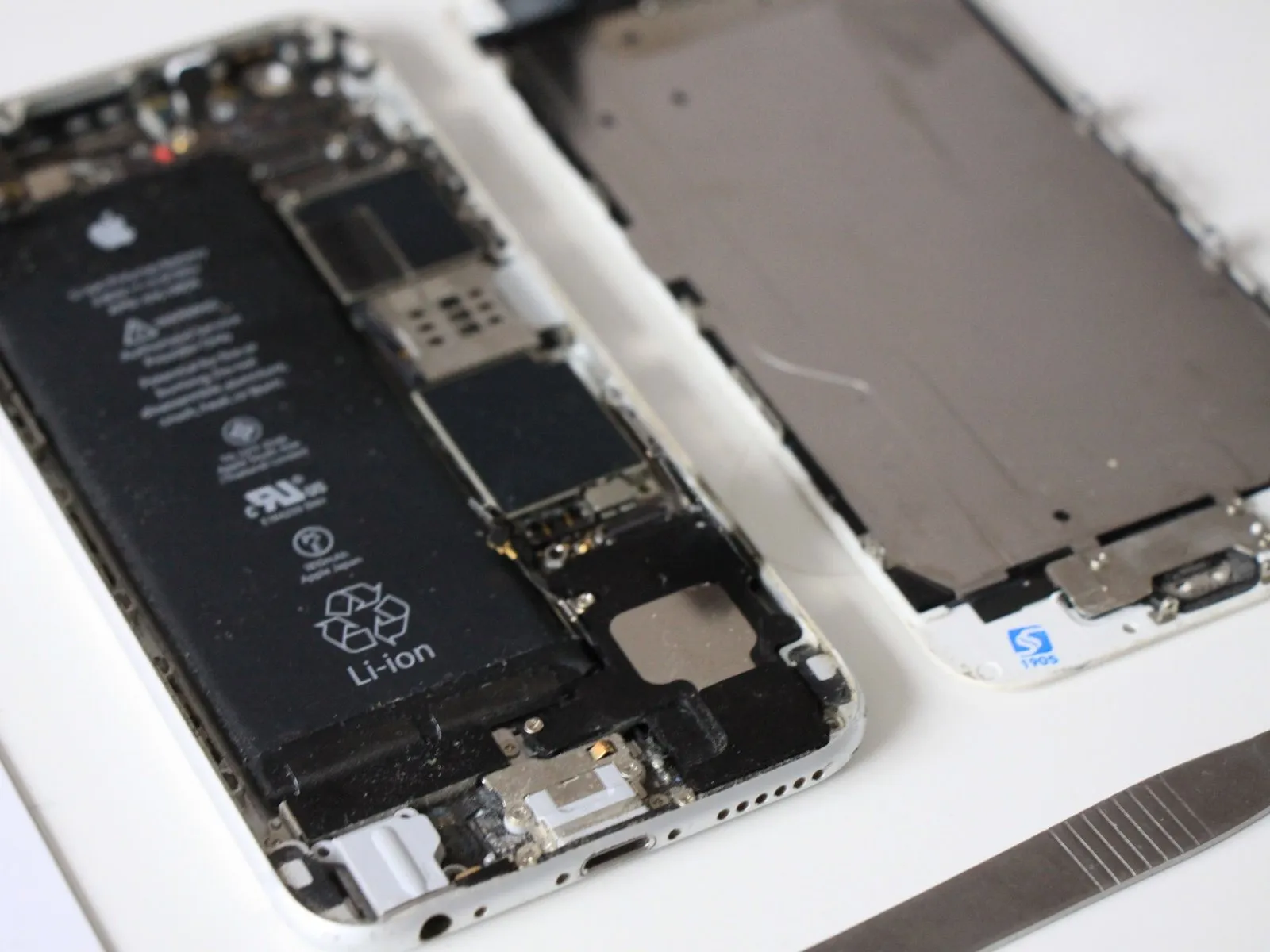
Having accessed the internal components by removing the front panel assembly, proceed to examine the iPhone 6's interior.
For secure handling during this procedure, it is recommended to maintain a two-handed grip on the iPhone, as it is susceptible to damage if dropped.
Having accessed the internal components by removing the front panel assembly, proceed to examine the iPhone 6's interior.
Step 6
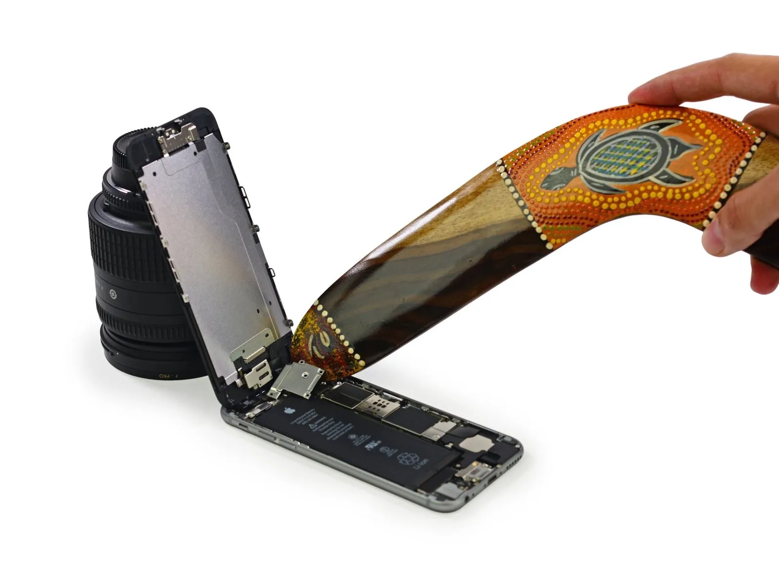
Due to the potential for misuse and risk of injury, any boomerang techniques demonstrated during this disassembly should only be executed by trained experts or individuals directly supervised by them; iFixit strongly advises against attempting to replicate these procedures.
According to consensus among Australian experts, the following steps detail the correct technique for throwing a boomerang.
According to consensus among Australian experts, the following steps detail the correct technique for throwing a boomerang.
Step 7
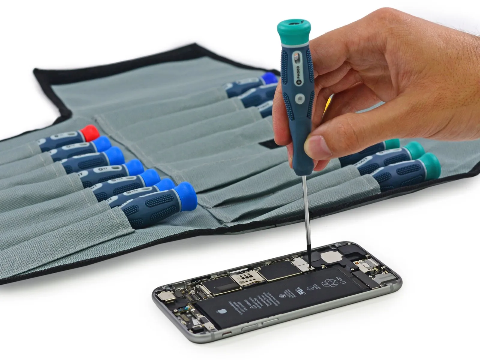
Although external components are unlikely to use Phillips head screws, the internal components do, but the included Pro Tech Screwdriver Set is equipped to manage all screw types encountered during disassembly.
Using a screwdriver, loosen and remove the screws holding the front panel assembly to the metal bracket.
Using a screwdriver, loosen and remove the screws holding the front panel assembly to the metal bracket.
Step 8
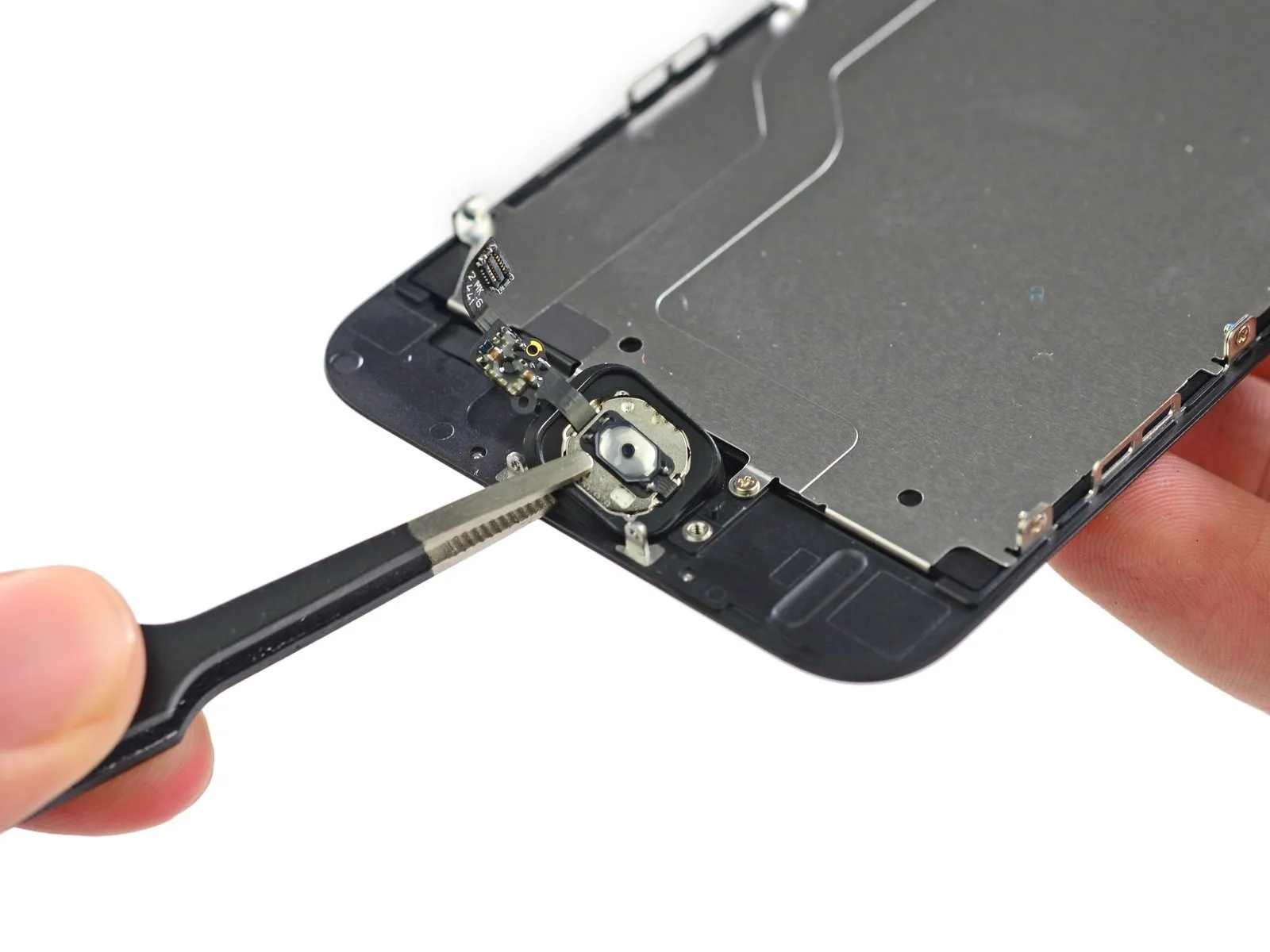
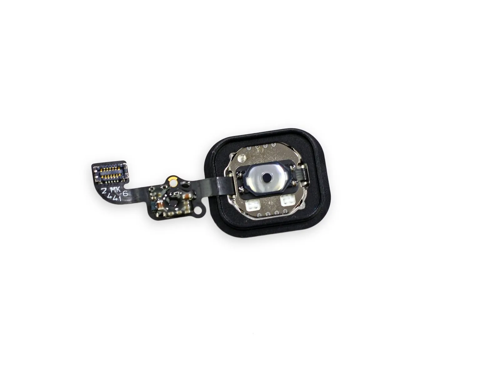
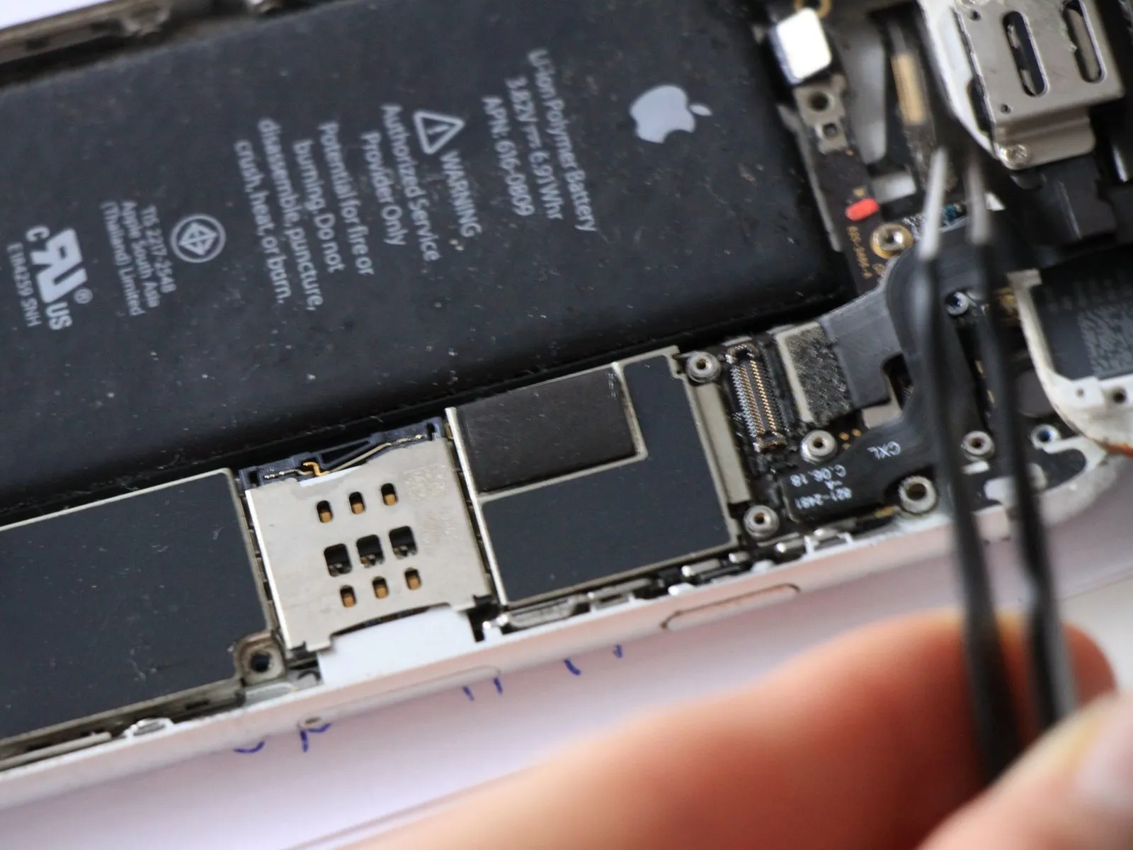
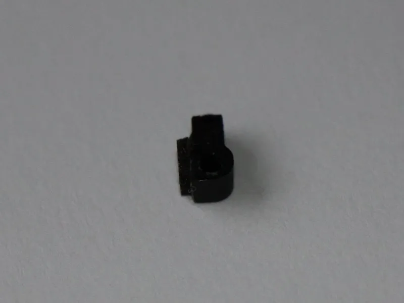
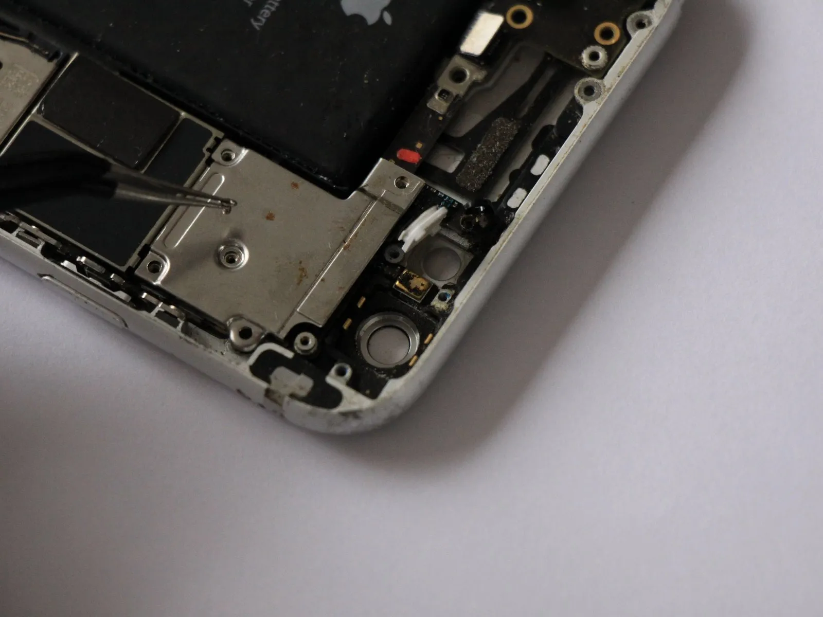
Carefully separate the home button from the front panel assembly, noting that the adjacent rubber gasket is prone to damage and requires a delicate touch.
Step 9
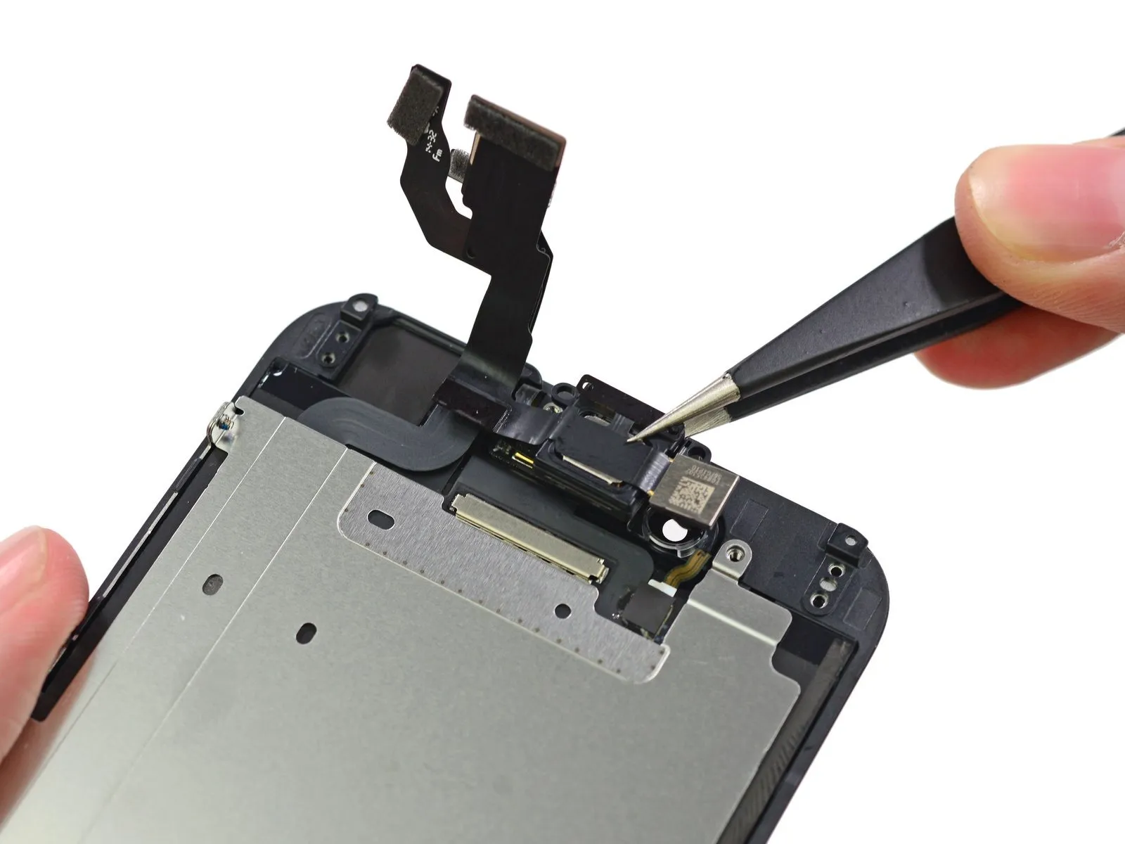
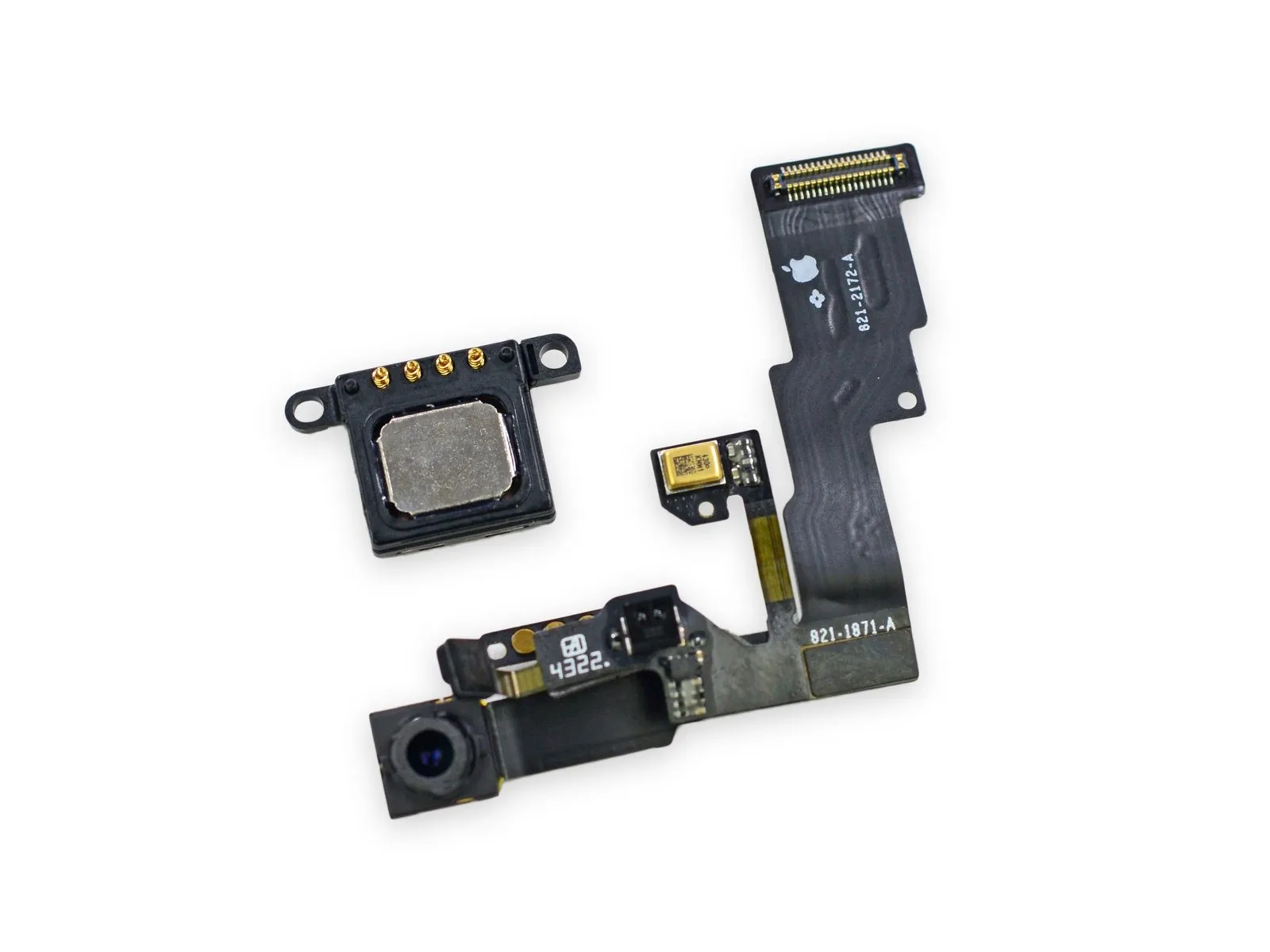
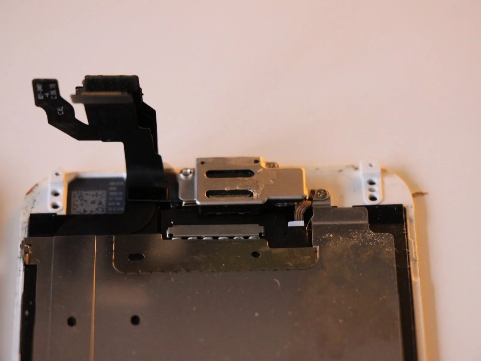
The front panel assembly, similar to that of the iPhone 6 Plus, incorporates both the front camera and the earpiece speaker.
Carefully remove the components and arrange them in a row for examination.
Carefully remove the components and arrange them in a row for examination.
Step 10
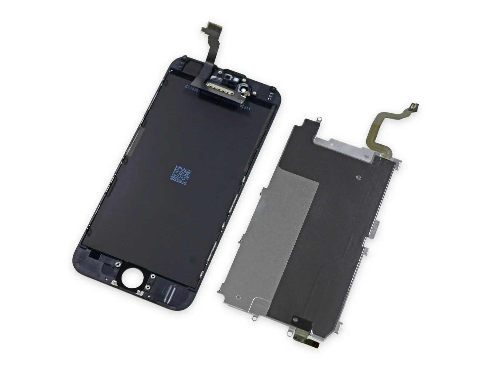
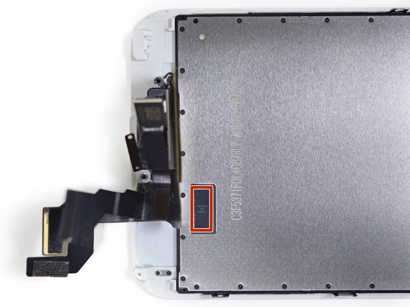
The internal design and assembly of this iPhone 6 closely mirrors that of the larger iPhone 6 Plus.
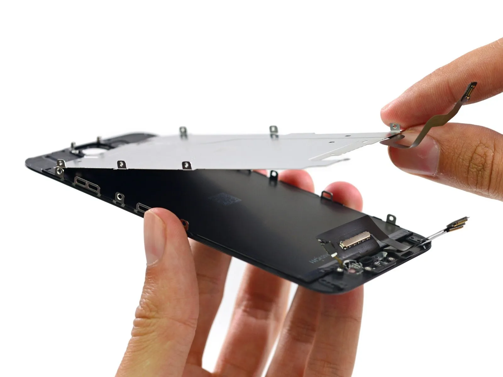
The construction of this metal plate and the front panel assembly it protects closely resembles that of the iPhone 6 Plus, a design change considered an upgrade.
The construction of this metal plate and the front panel assembly it protects closely resembles that of the iPhone 6 Plus, a design change considered an upgrade.
Step 11
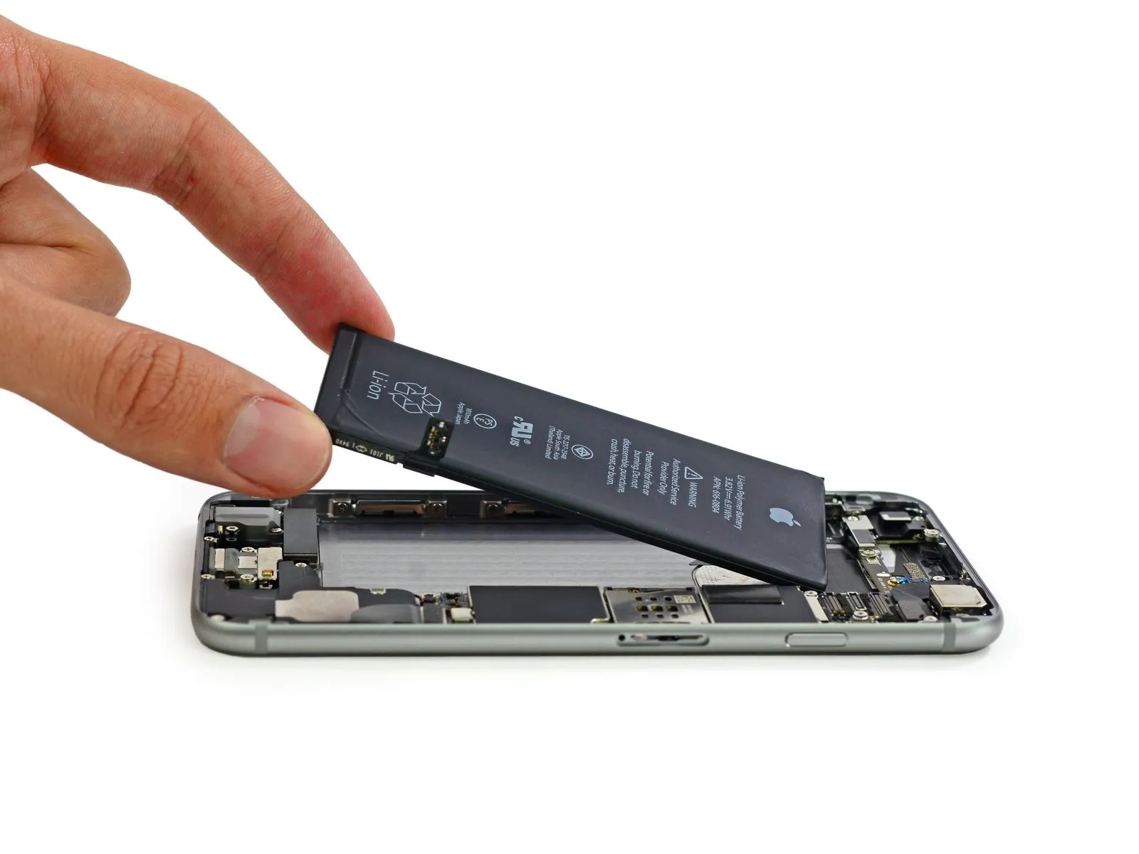
Employing these tabs, when properly extended, provides a safe and convenient method for battery removal, eliminating the need for potentially damaging prying tools.
Like a 3M Command strip, this adhesive is designed to detach cleanly when the tab is removed in the proper manner, causing the entire adhesive section to separate.
Like a 3M Command strip, this adhesive is designed to detach cleanly when the tab is removed in the proper manner, causing the entire adhesive section to separate.
Step 12
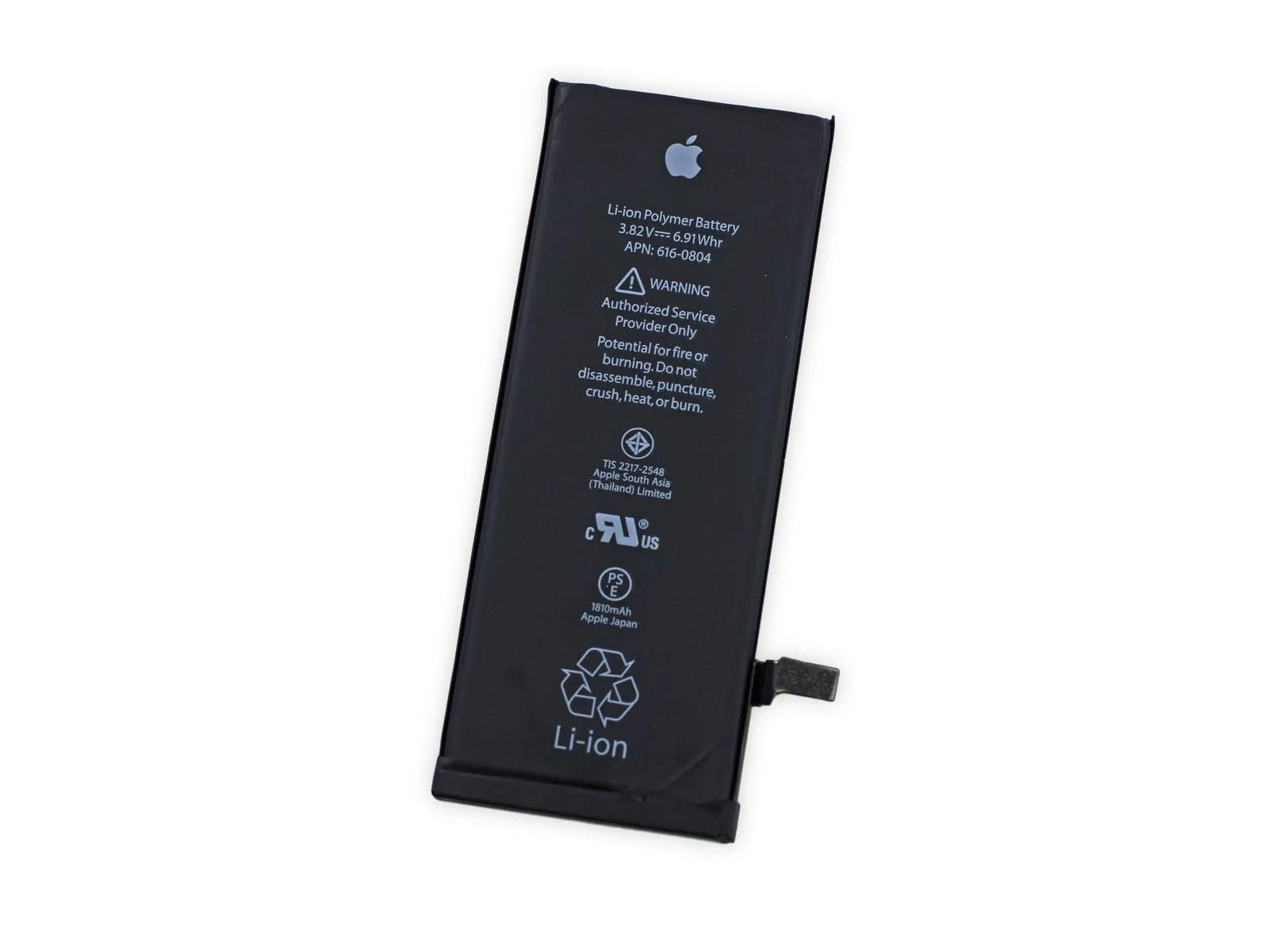
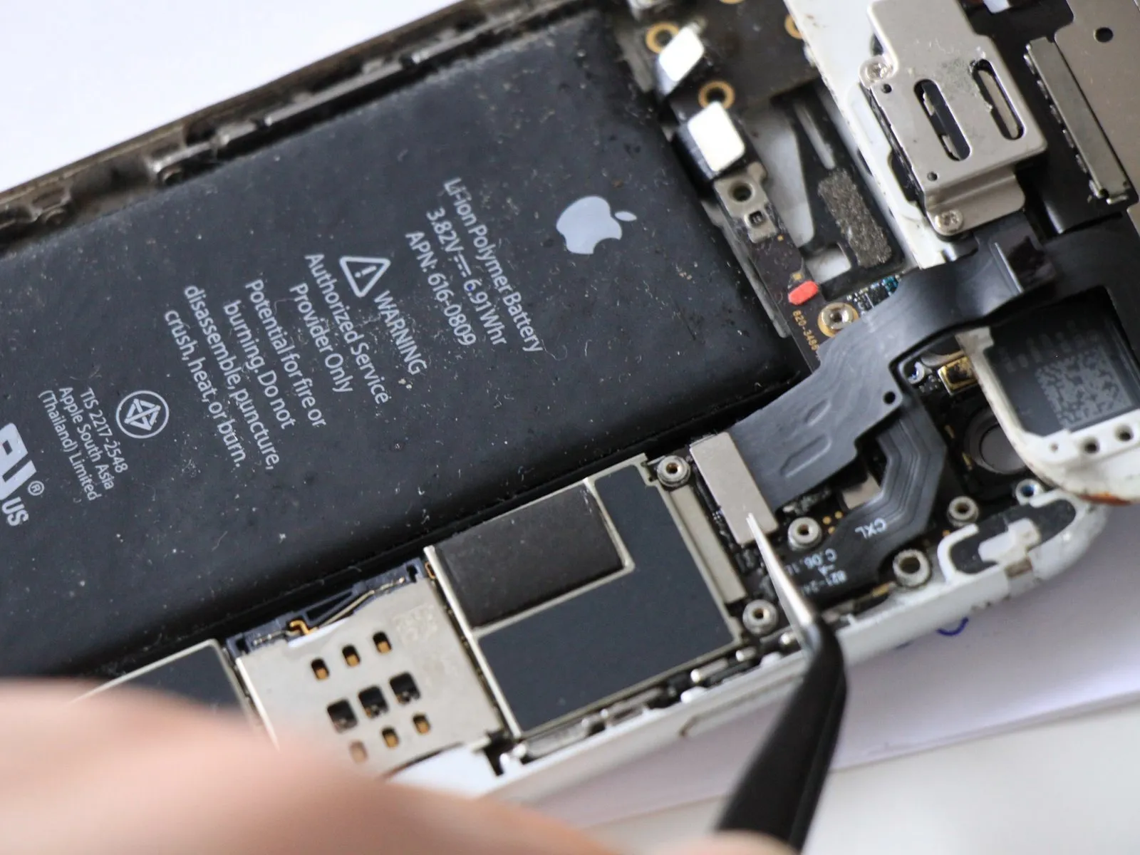
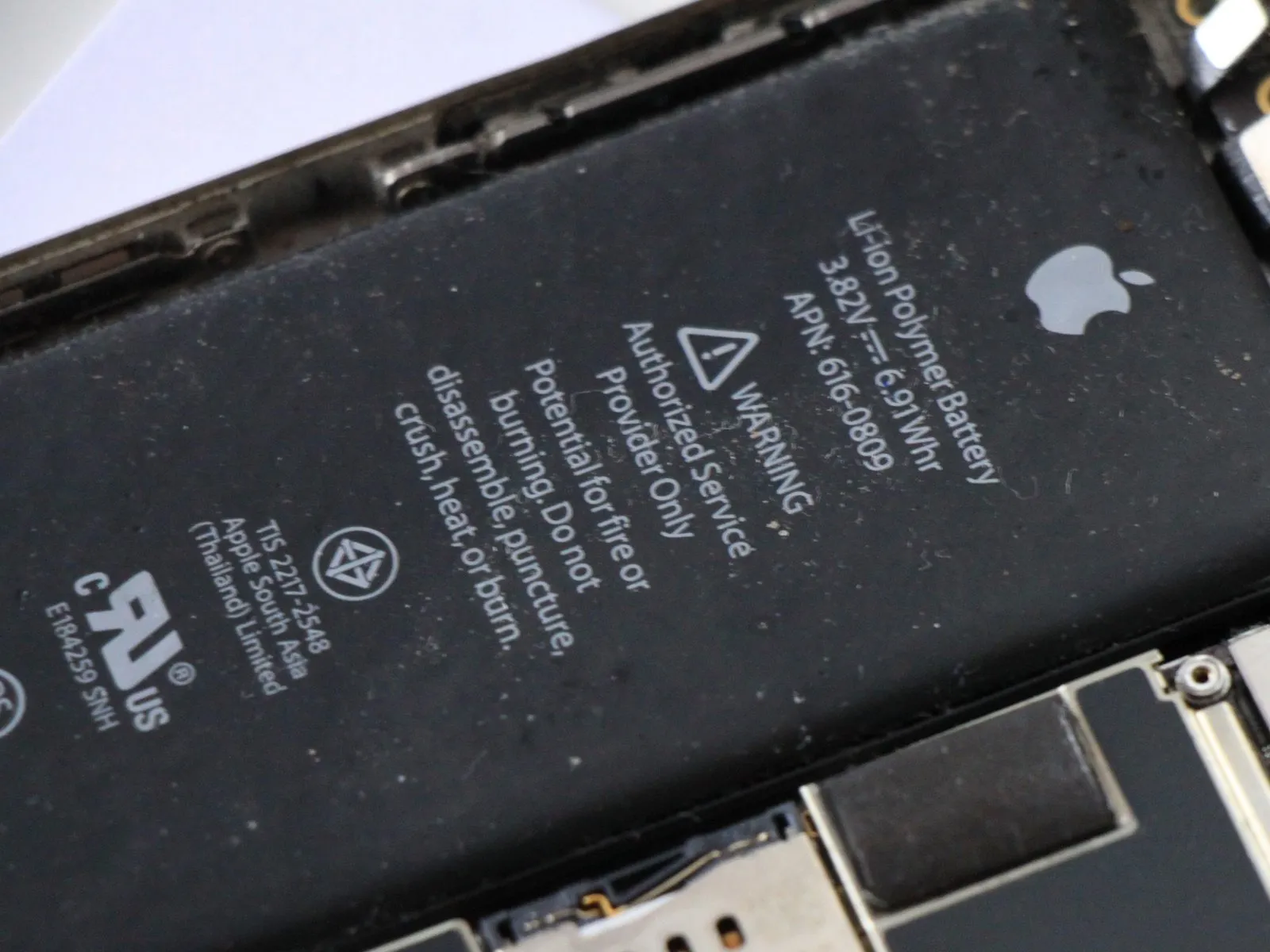
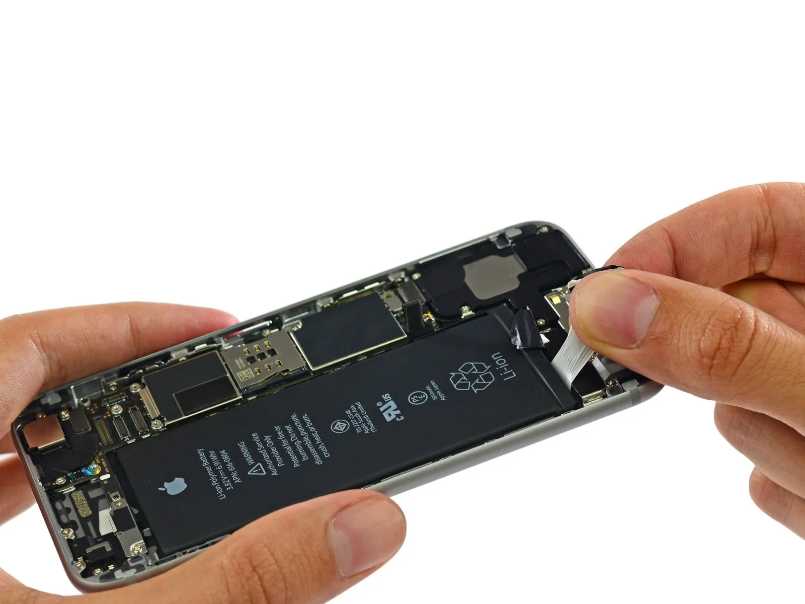
The iPhone 6's battery is a Lithium-ion Polymer type, rated at 3.82 V and 1810 mAh, providing 6.91 Wh of energy; the rear-facing rating is 7.01 Wh, suggesting a slight increase in capacity achieved after initial labeling.
According to Apple, the 28-gram power pack, measuring 3.75 inches by 1.5 inches by 0.13 inches, provides up to 14 hours of talk time when using a 3G connection and a standby time of 250 hours.
Although its 11.1 Wh capacity and 2915 mAh represent a smaller battery than the iPhone 6 Plus, it still offers a significant increase in power compared to the 1560 mAh battery found within the iPhone 5s.
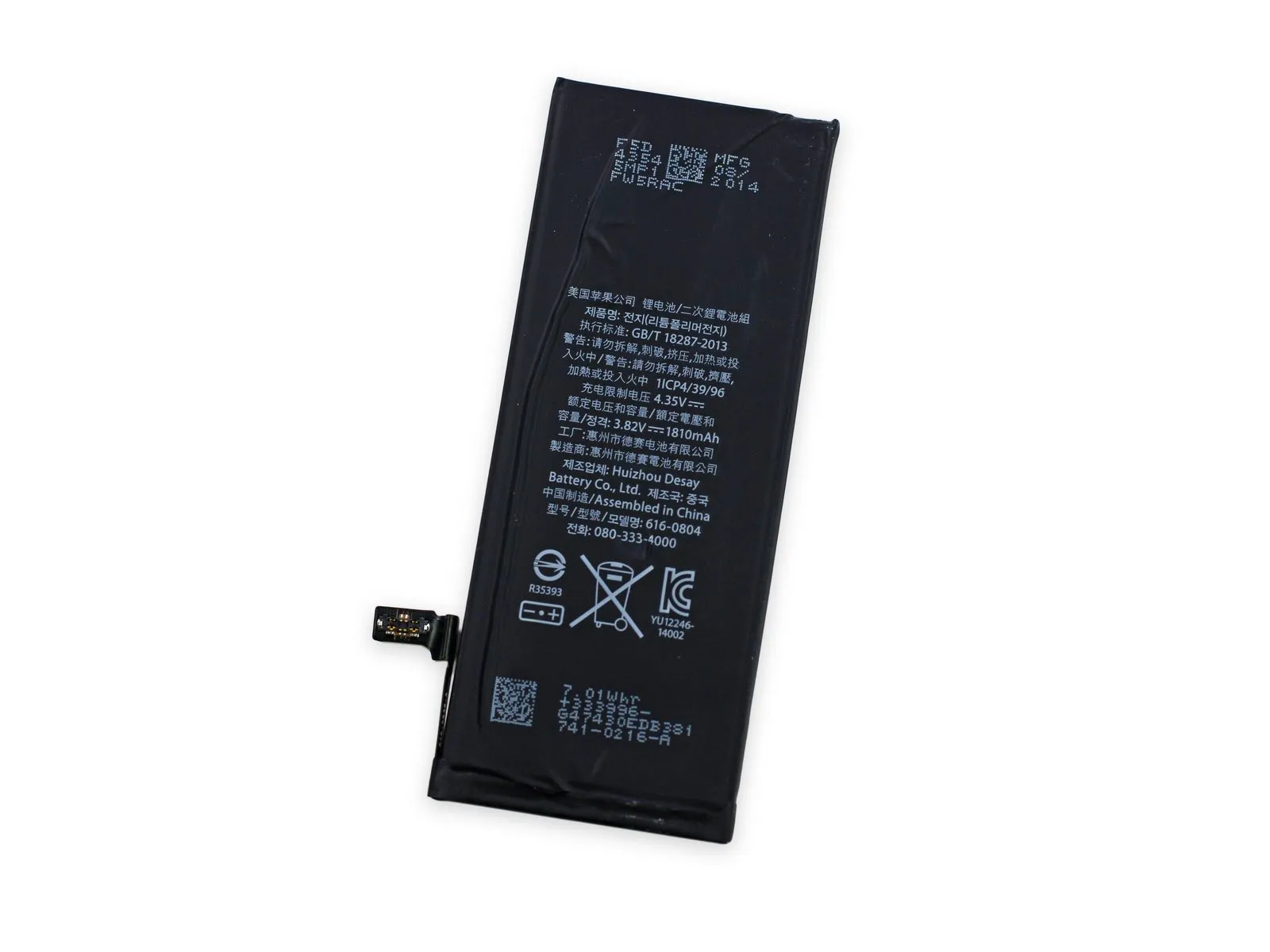
The battery's exterior displays conflicting manufacturer information; while the front indicates production by Apple South Asia (Thailand) Limited and Apple Japan, the rear confirms its origin as being manufactured in Huizhou, China.
According to Apple, the 28-gram power pack, measuring 3.75 inches by 1.5 inches by 0.13 inches, provides up to 14 hours of talk time when using a 3G connection and a standby time of 250 hours.
Although its 11.1 Wh capacity and 2915 mAh represent a smaller battery than the iPhone 6 Plus, it still offers a significant increase in power compared to the 1560 mAh battery found within the iPhone 5s.
The battery's exterior displays conflicting manufacturer information; while the front indicates production by Apple South Asia (Thailand) Limited and Apple Japan, the rear confirms its origin as being manufactured in Huizhou, China.
Step 13
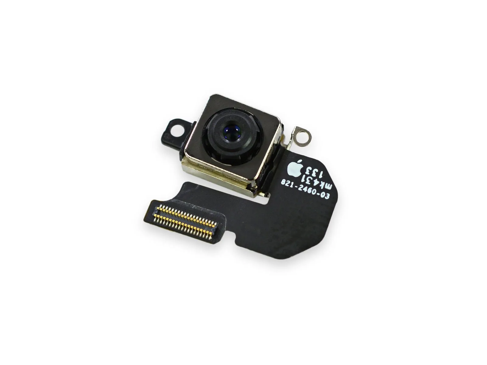
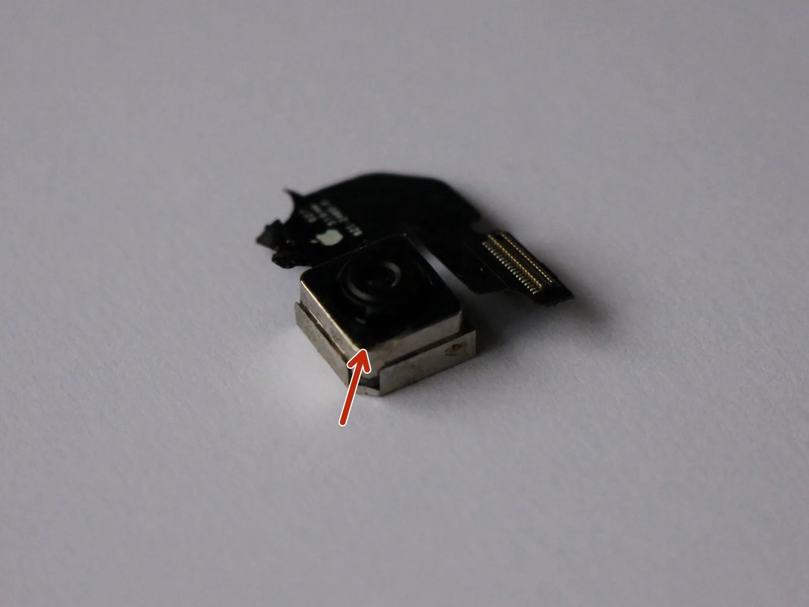
Using tweezers, carefully detach the rear camera assembly.
Despite not incorporating the iPhone 6 Plus’s advanced optical image stabilization, this component replicates nearly all other specifications, including an 8-megapixel resolution, f/2.2 aperture, True Tone flash functionality, and phase-detection autofocus capabilities.
Employing digital methods, the device simulates the functionality of optical image stabilization (OIS) to reduce image blur.
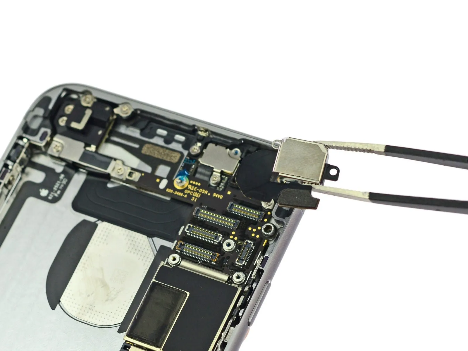
Step 14
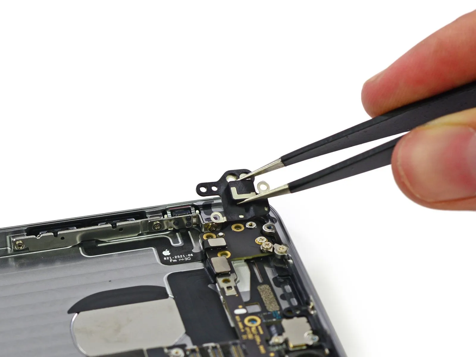
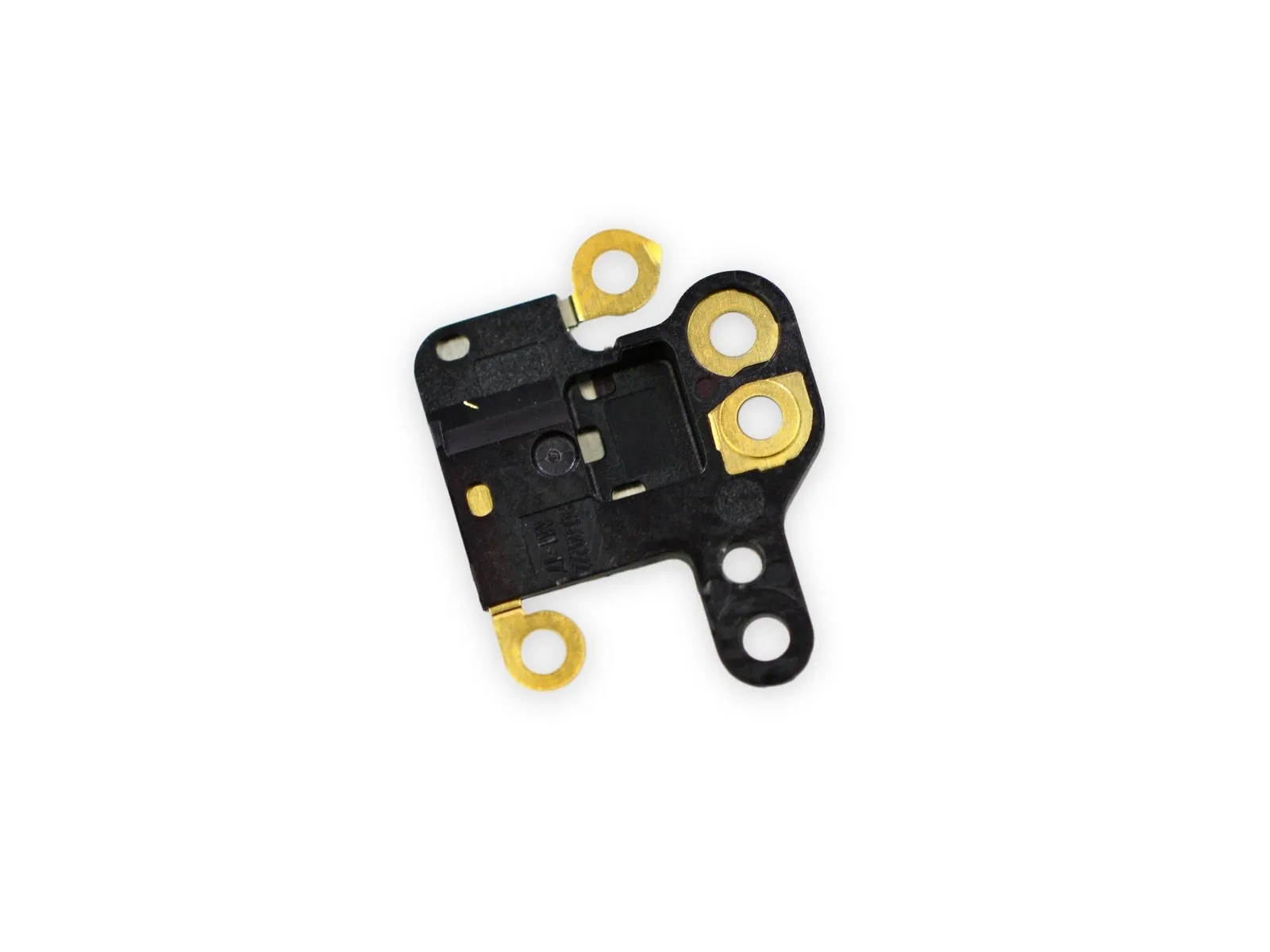
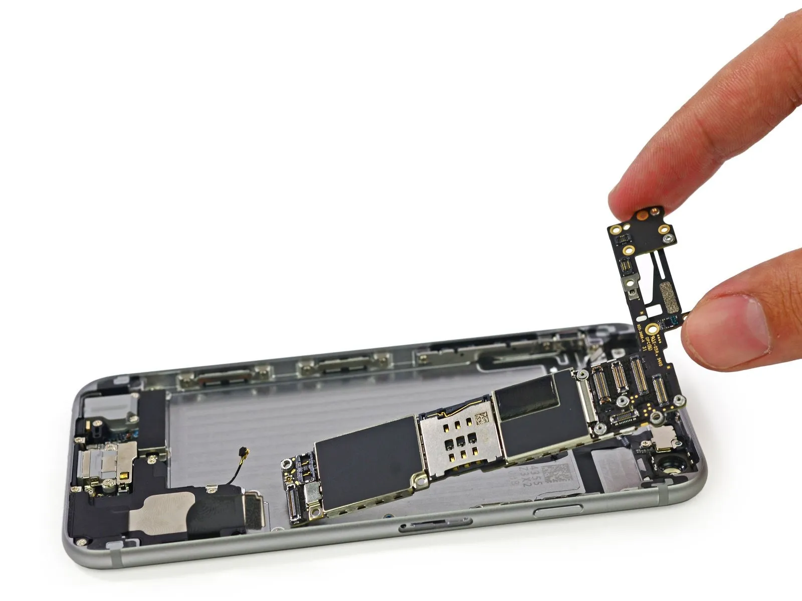
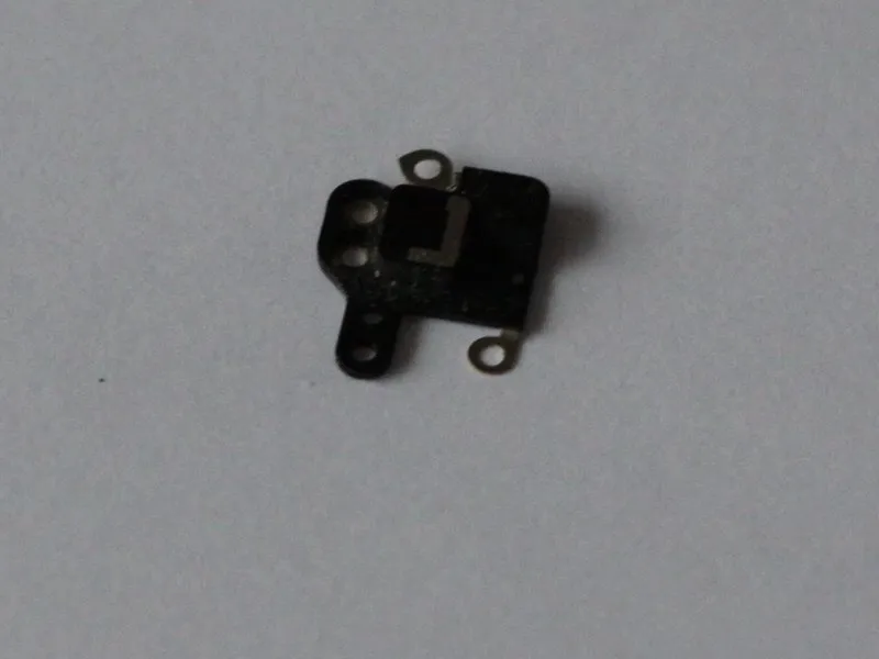
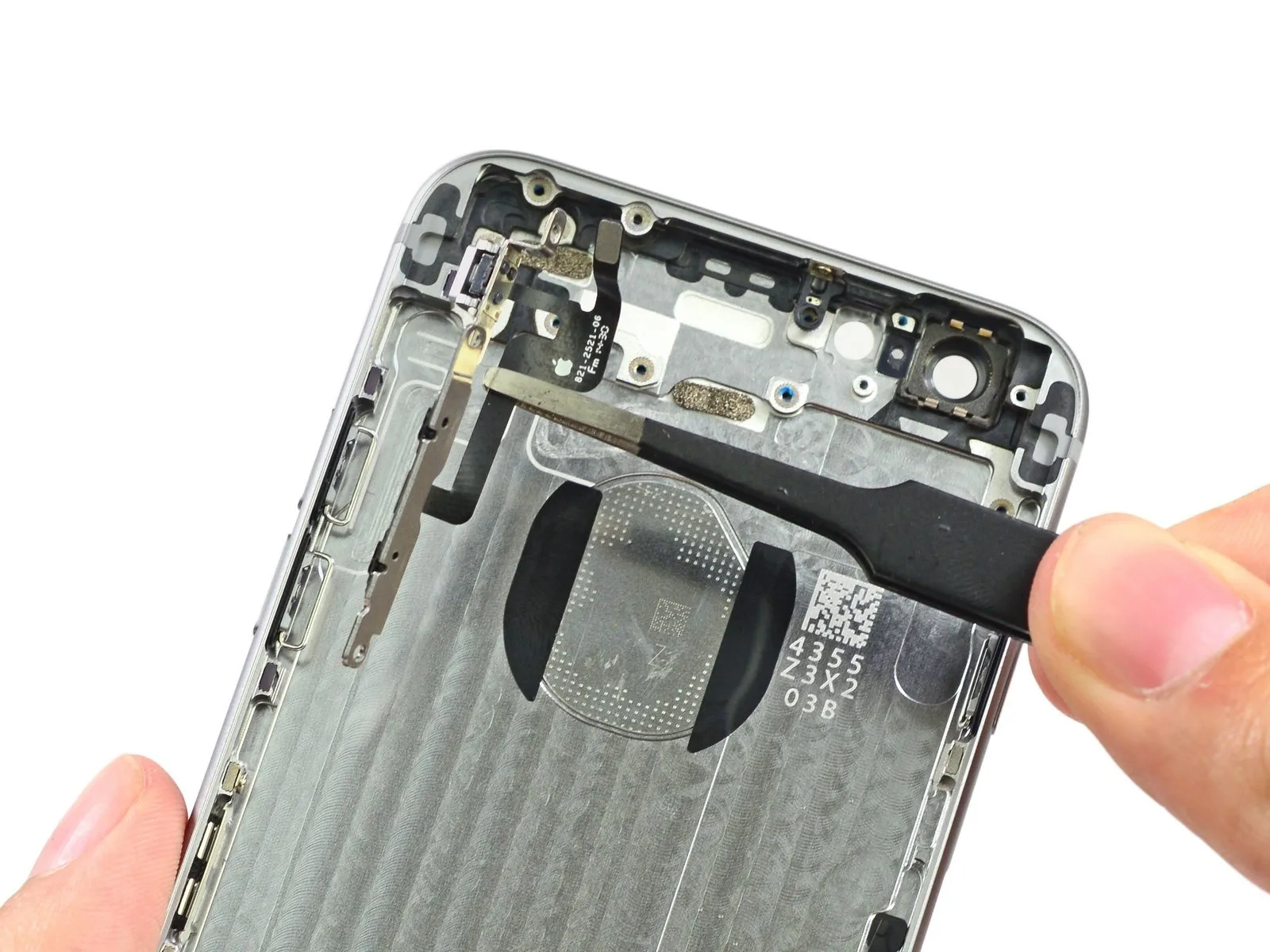
Carefully extract the antennas using tweezers, completing the process rapidly.
Become proficient in using the device and proceed to the next step.
Carefully remove the electromagnetic interference shielding from the logic board to expose the underlying components.
Become proficient in using the device and proceed to the next step.
Carefully remove the electromagnetic interference shielding from the logic board to expose the underlying components.
Step 15
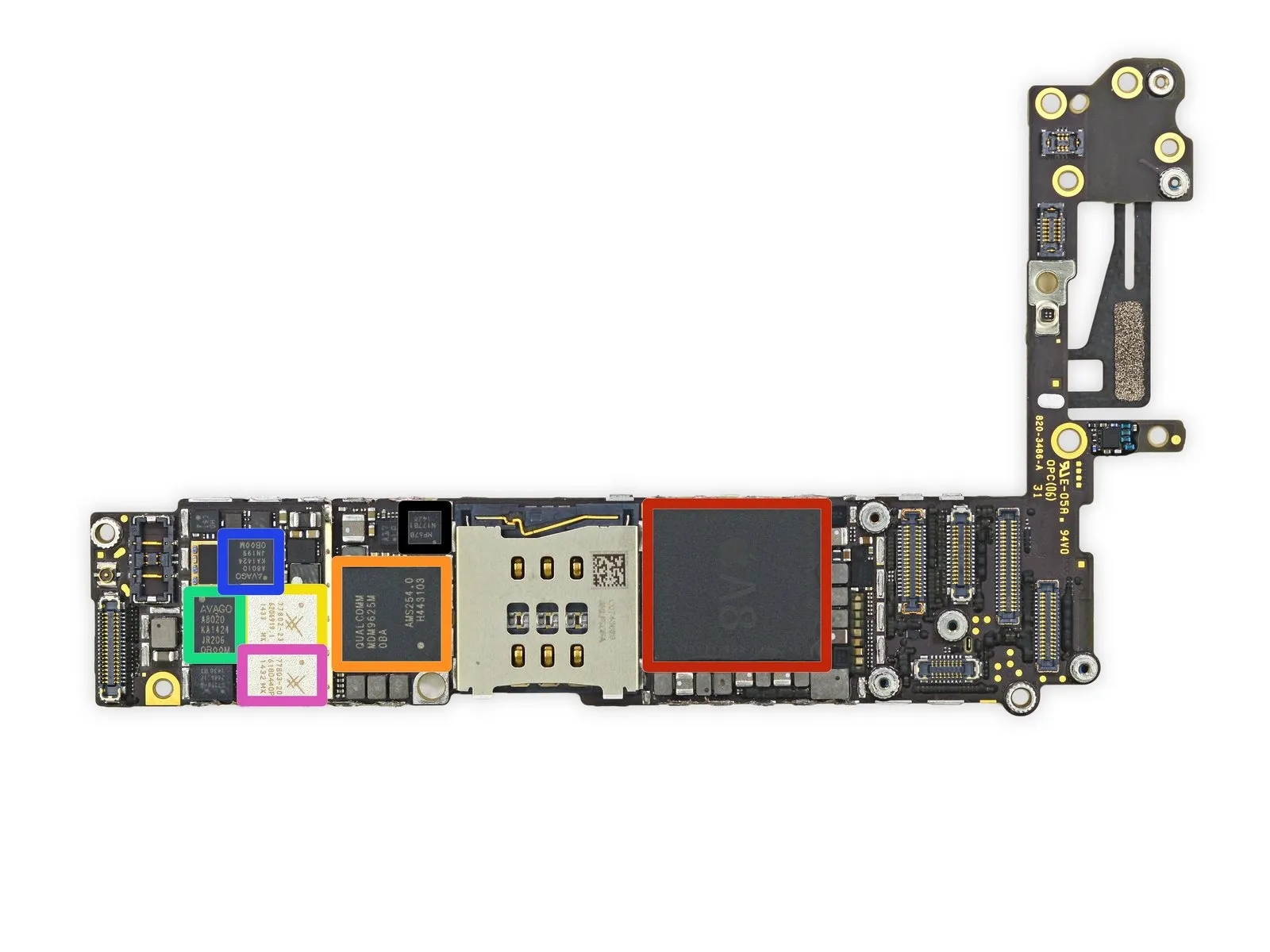
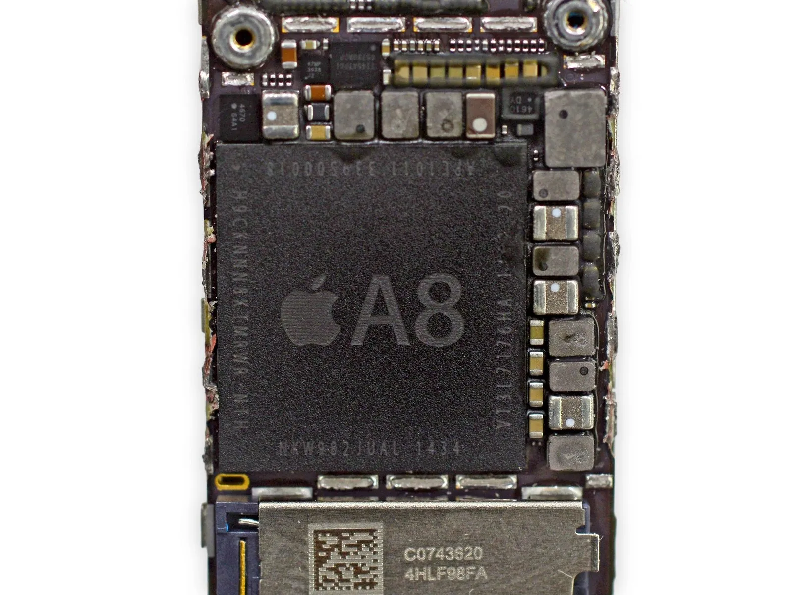
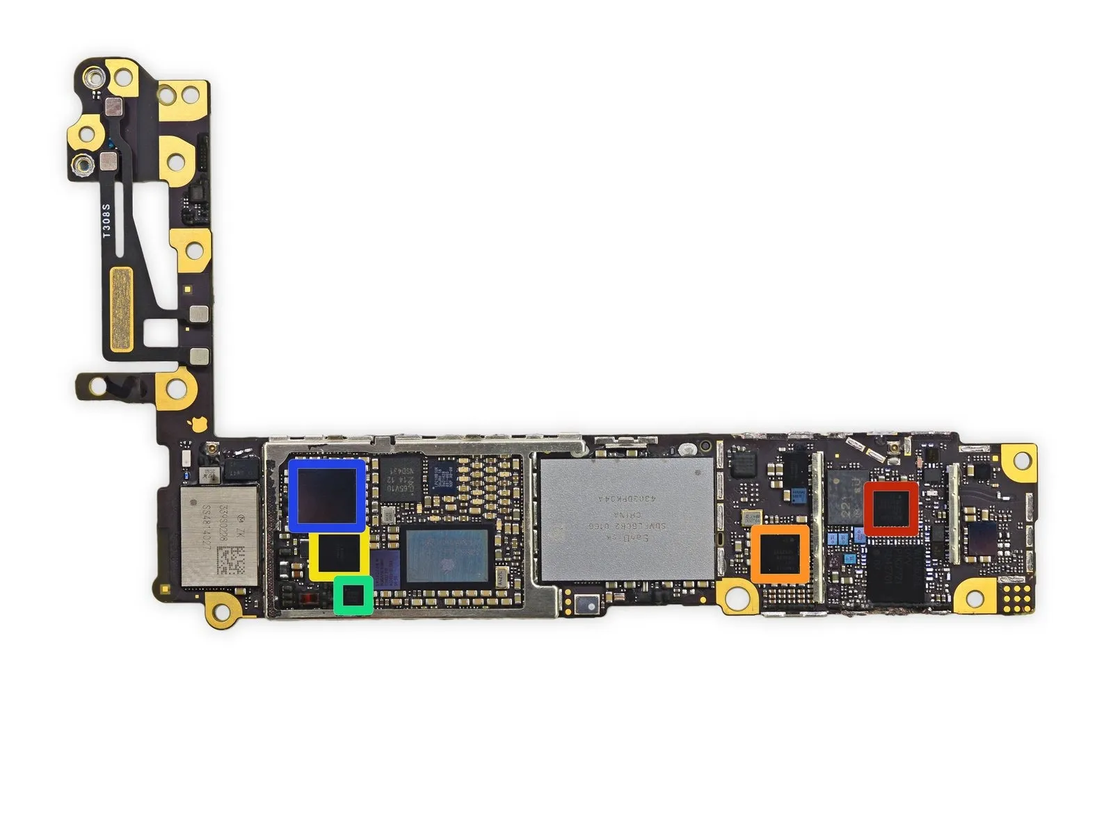
Carefully examine the logic board's anterior surface.
The Apple A8 APL1011 system-on-chip incorporates SK Hynix RAM, identifiable by the code H9CKNNN8KTMRWR-NTH, which is likely 1 GB of LPDDR3 memory, consistent with the iPhone 6 Plus configuration.
LTE modem, model MDM9625M, manufactured by Qualcomm.
Skyworks 77802-23, a low-band LTE pad.
The device is an Avago A8020 High Band PAD.
Employ Avago A8010 power amplifiers combined with FBAR resonators.
Mid-band LTE PAD, manufactured by Skyworks, model number 77803-20.
The InvenSense MP67B integrates a gyroscope and accelerometer into a single device.
Step 16
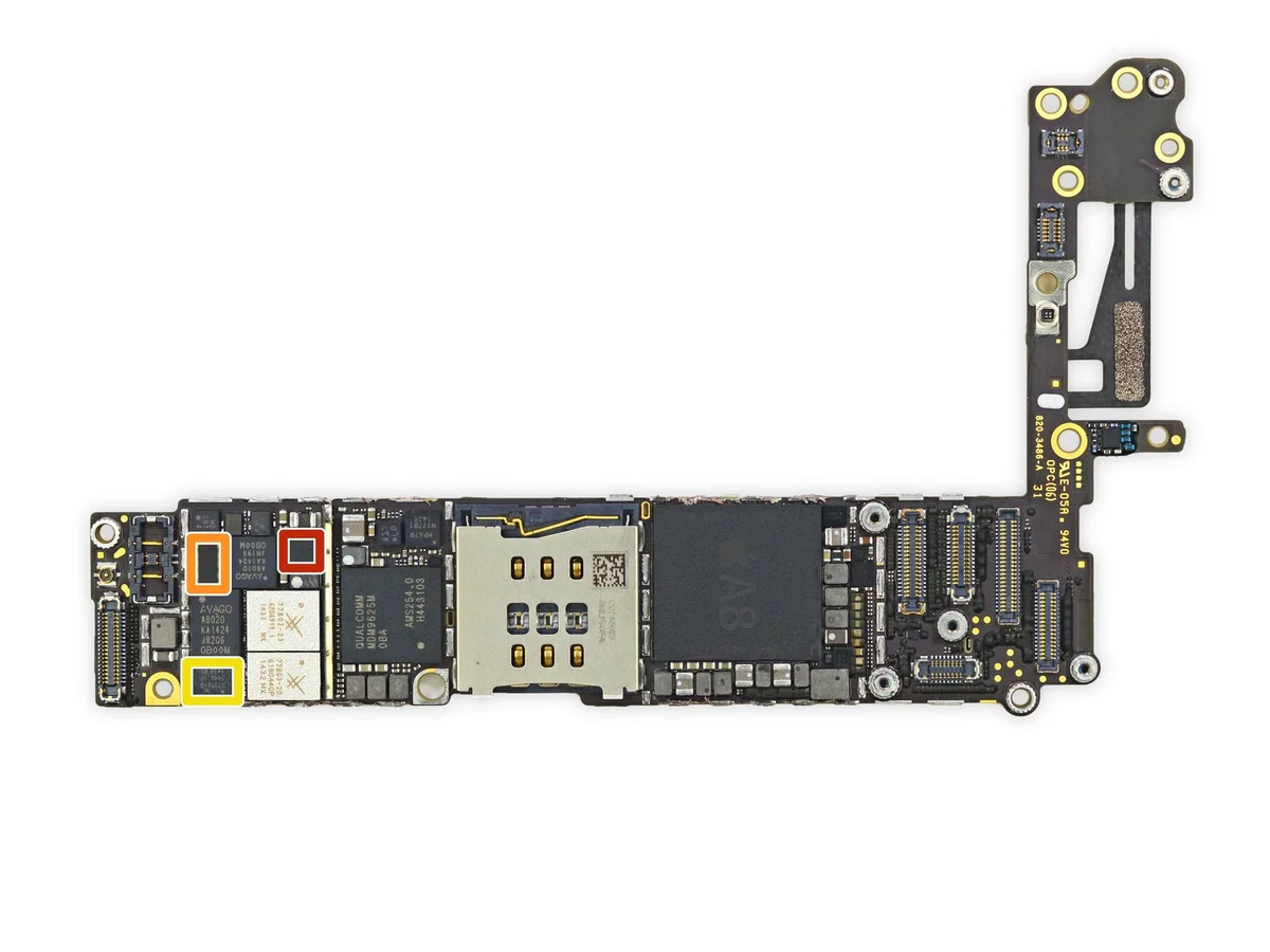
Additional integrated circuits are located on the logic board's front surface.
- The device is a Qualcomm QFE1100 integrated circuit designed for envelope tracking.
- The RF5159 is an antenna switch module manufactured by RF Micro Devices.
- Mid-band PAD, manufactured by Skyworks, model number 77356-8.
Step 17
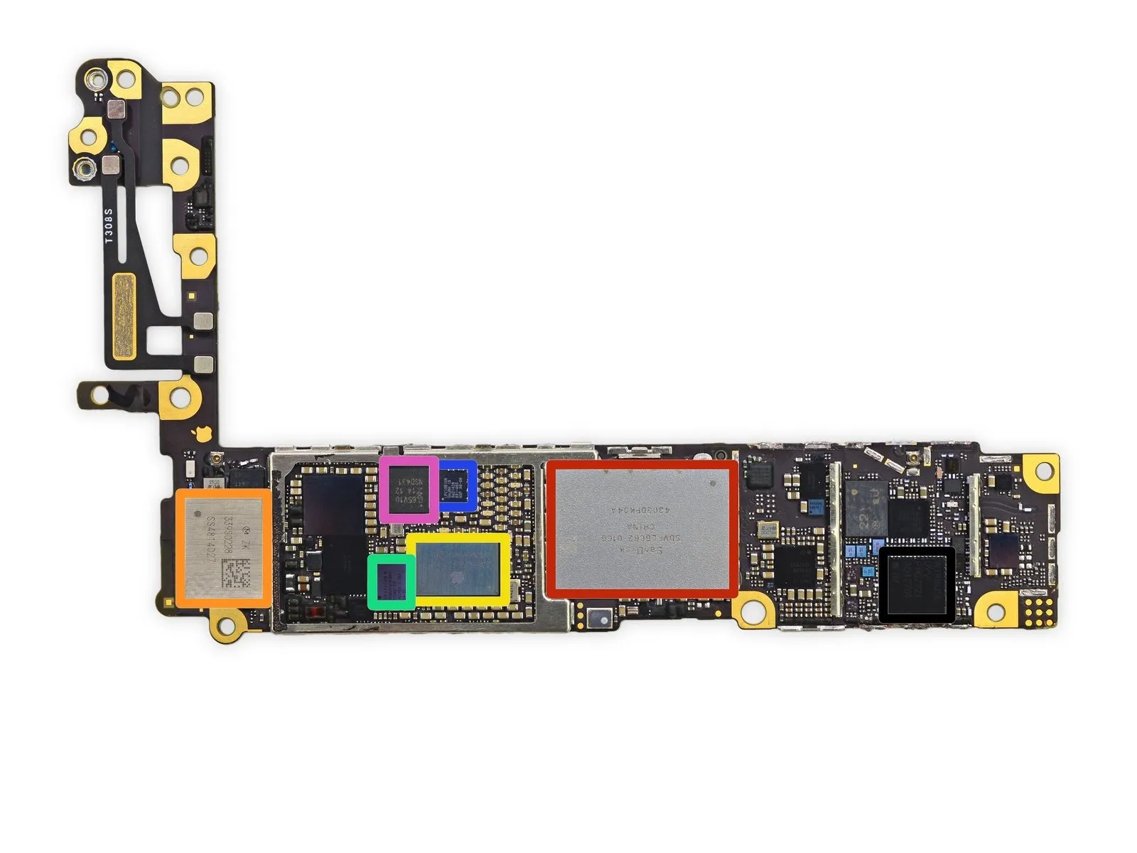
Carefully examine the underside of the logic board.
- This is a SanDisk SDMFLBCB2 NAND flash memory module with a capacity of 128 Gigabytes, functionally equivalent to 16 Gigabytes.
- Wi-Fi functionality is provided by the Murata 339S0228 module.
- Power management functionality is handled by the Apple/Dialog 338S1251-AZ integrated circuit.
- The device incorporates a Broadcom BCM5976 touchscreen controller.
- The M8 motion coprocessor, alternatively referred to as the NXP LPC18B1UK, utilizes an ARM Cortex-M3 microcontroller architecture.
- The device incorporates an NXP PN544 NFC controller within an NXP 65V10 NFC module that also functions as a secure element.
- RF transceiver: Qualcomm WTR1625L.
Step 18

Additional integrated circuits are located on the underside of the logic board.
- Carrier aggregation functionality with the WTR1625L necessitates the use of the Qualcomm WFR1620, a receive-only companion chip, as specified by Qualcomm.
- The power management integrated circuit is a Qualcomm PM8019.
- The device is a Texas Instruments 343S0694 Touch Transmitter.
- The AMS AS3923 NFC Booster IC enhances the functionality of existing NFC controllers, particularly beneficial in demanding applications like mobile devices and wearables, while simultaneously easing antenna design constraints.
- This component functions as an NFC frontend, designed to enhance operation in conditions with significant interference, supporting data transfer speeds reaching a maximum of 212kb/s for peer-to-peer communication.
- The audio codec is a Cirrus Logic 338S1201.
Step 19
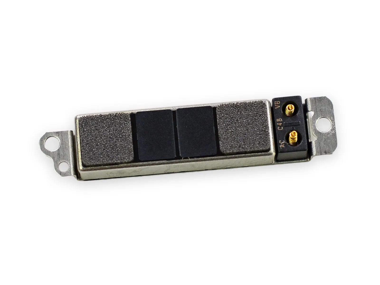
Carefully detach the vibrator assembly, noting the manufacturer's claim of design enhancements.
Selecting a vibrator mechanism often presents a subjective preference, similar to choosing between competing brands like Coca-Cola and Pepsi, as there is no universally superior option.
Due to frequent design revisions by Apple for this component, proceed with caution.
Selecting a vibrator mechanism often presents a subjective preference, similar to choosing between competing brands like Coca-Cola and Pepsi, as there is no universally superior option.
Due to frequent design revisions by Apple for this component, proceed with caution.
- The iPhone 4 incorporates a counterweight.
- Apple iPhone 4S, utilizing linear oscillation technology.
- The iPhone 5 or 5s incorporates a counterweight.
Step 20
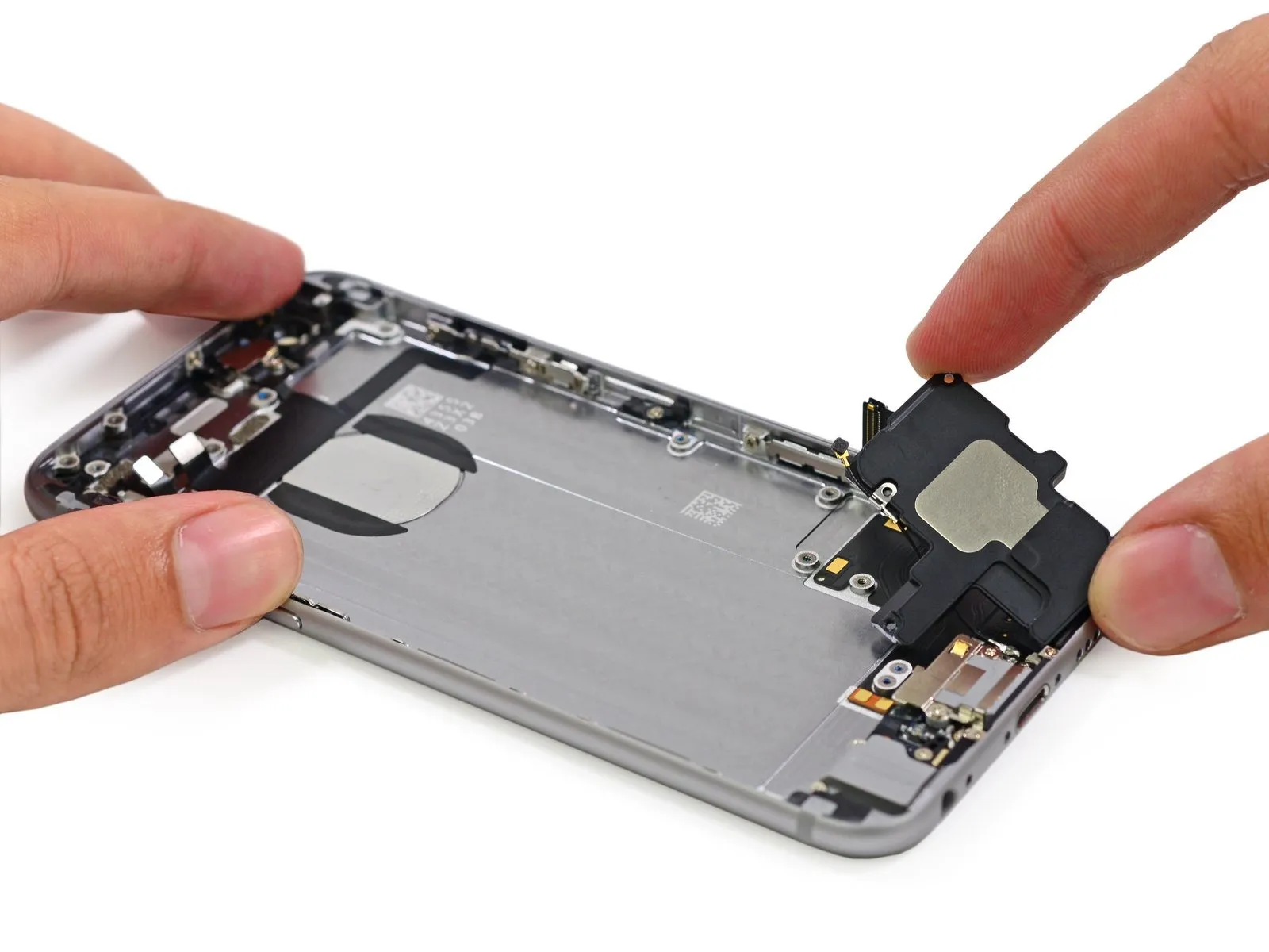
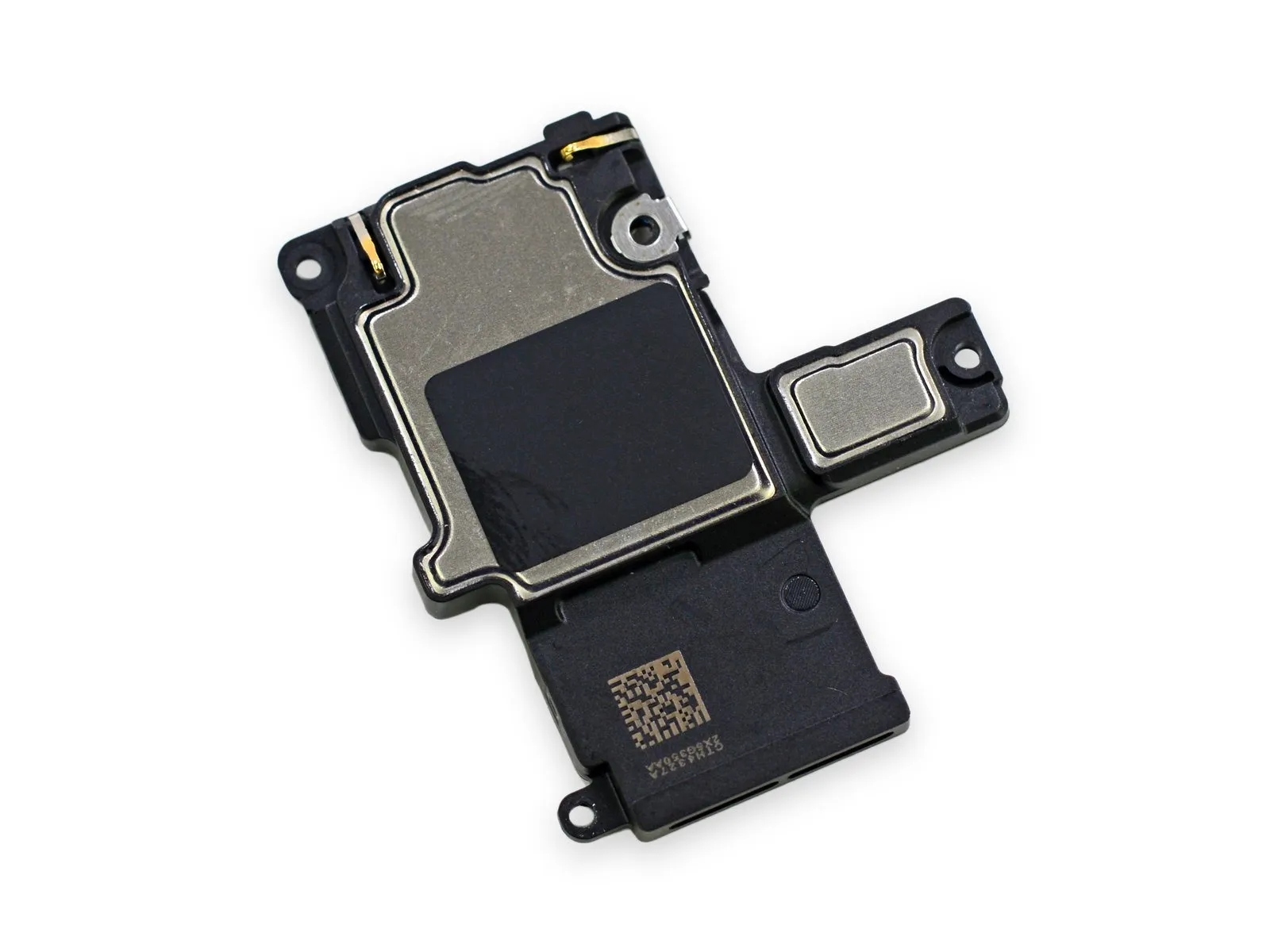
The speaker assembly has been redesigned for this model year.
Due to the limited identifying features, it's likely this speaker is a small revision of the iPhone 5s speaker.
Due to the limited identifying features, it's likely this speaker is a small revision of the iPhone 5s speaker.
Step 21
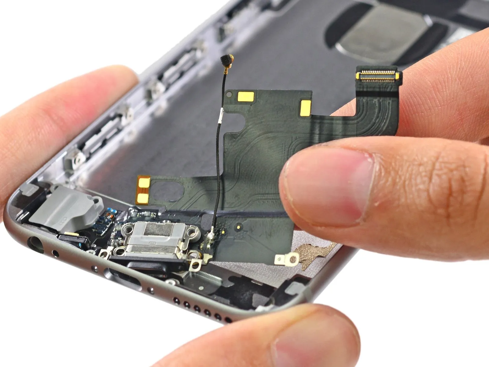
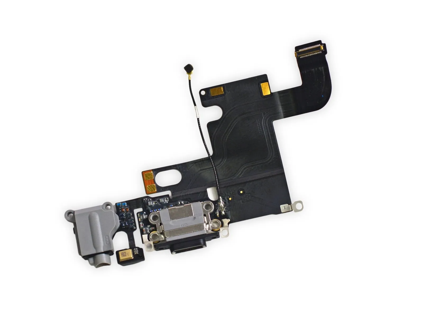
The headphone jack and Lightning connector are now permanently joined as a single unit, integrated within a single cable.
Because these components are now integrated, individual replacement is impossible; therefore, a faulty port necessitates replacing the entire assembly.
Because these components are now integrated, individual replacement is impossible; therefore, a faulty port necessitates replacing the entire assembly.
Step 22
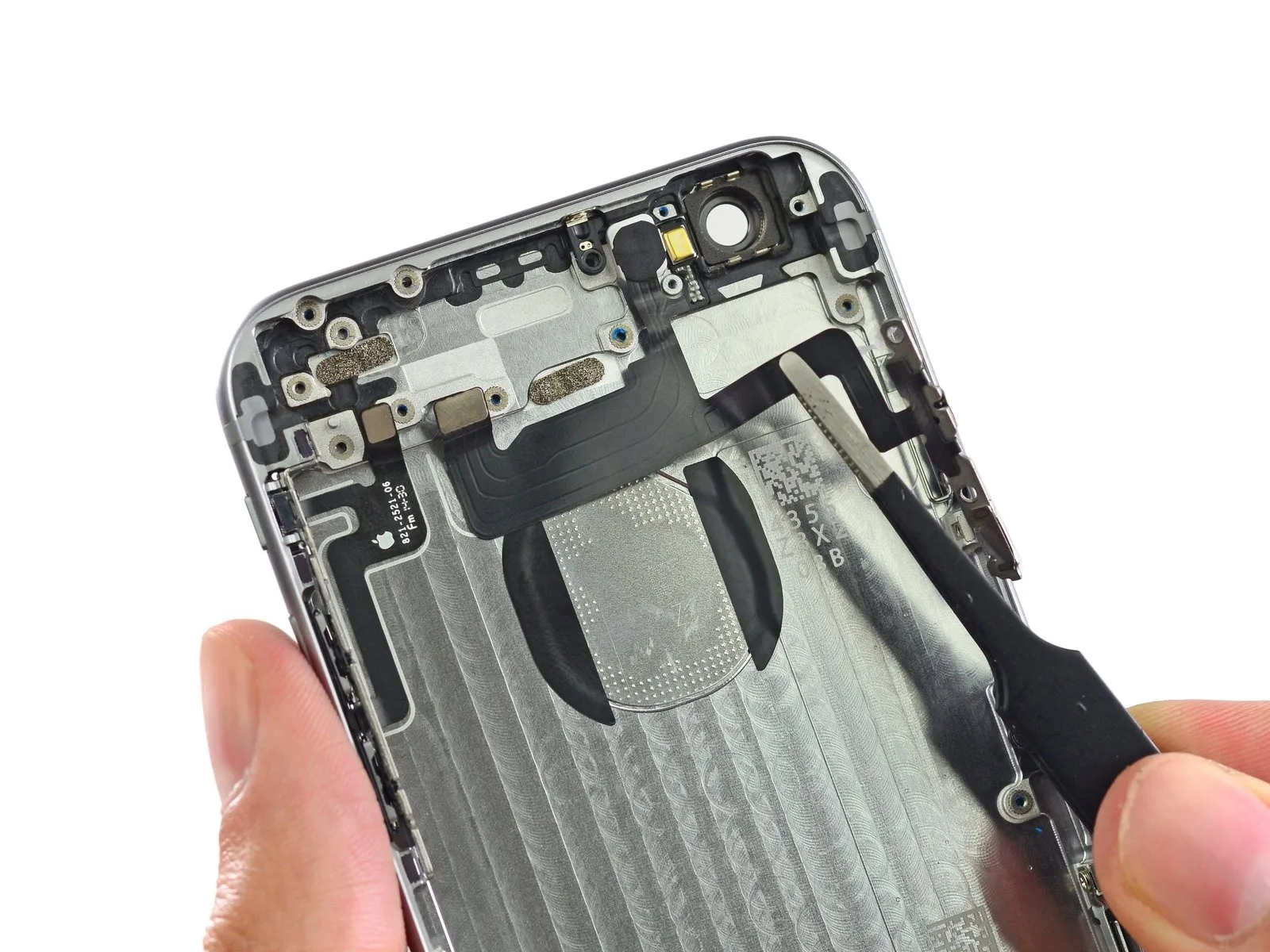
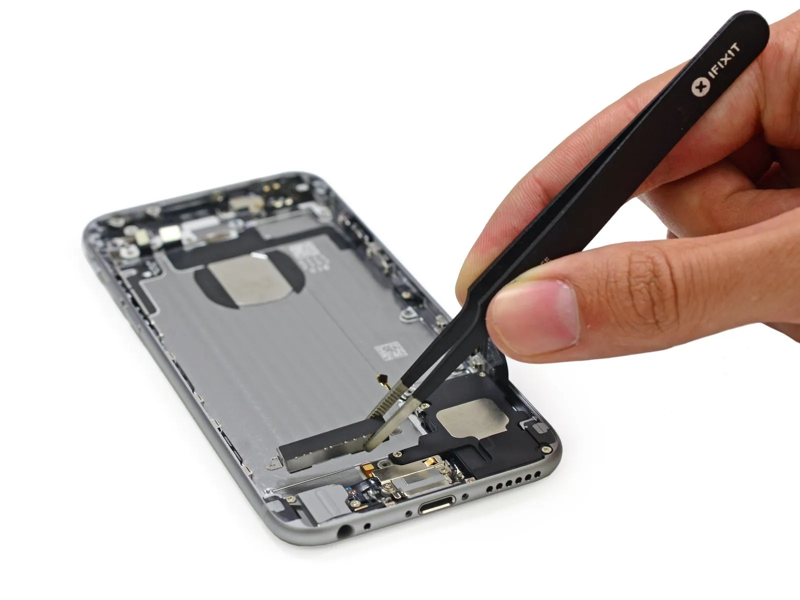
Employing tweezers facilitates manipulation of the fragile cable connectors, including those linked to the power and volume controls, enabling their careful separation.
Carefully remove the button assemblies from the iPhone enclosure.
The components exhibit a design closely mirroring those previously observed in iPhone 6 Plus models.
Carefully remove the button assemblies from the iPhone enclosure.
The components exhibit a design closely mirroring those previously observed in iPhone 6 Plus models.
Step 23
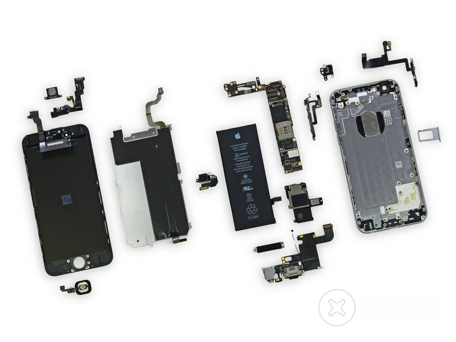

Concluding this assessment, the iPhone 6 achieves a score of 7 out of 10, reflecting its performance.
Like previous iPhone 5 models, the display unit is detached as the initial step in the repair process, which streamlines screen replacements.
Accessing the battery is relatively simple; however, it necessitates a specialized pentalobe screwdriver and familiarity with adhesive release methods for removal, though the process itself isn't complex.
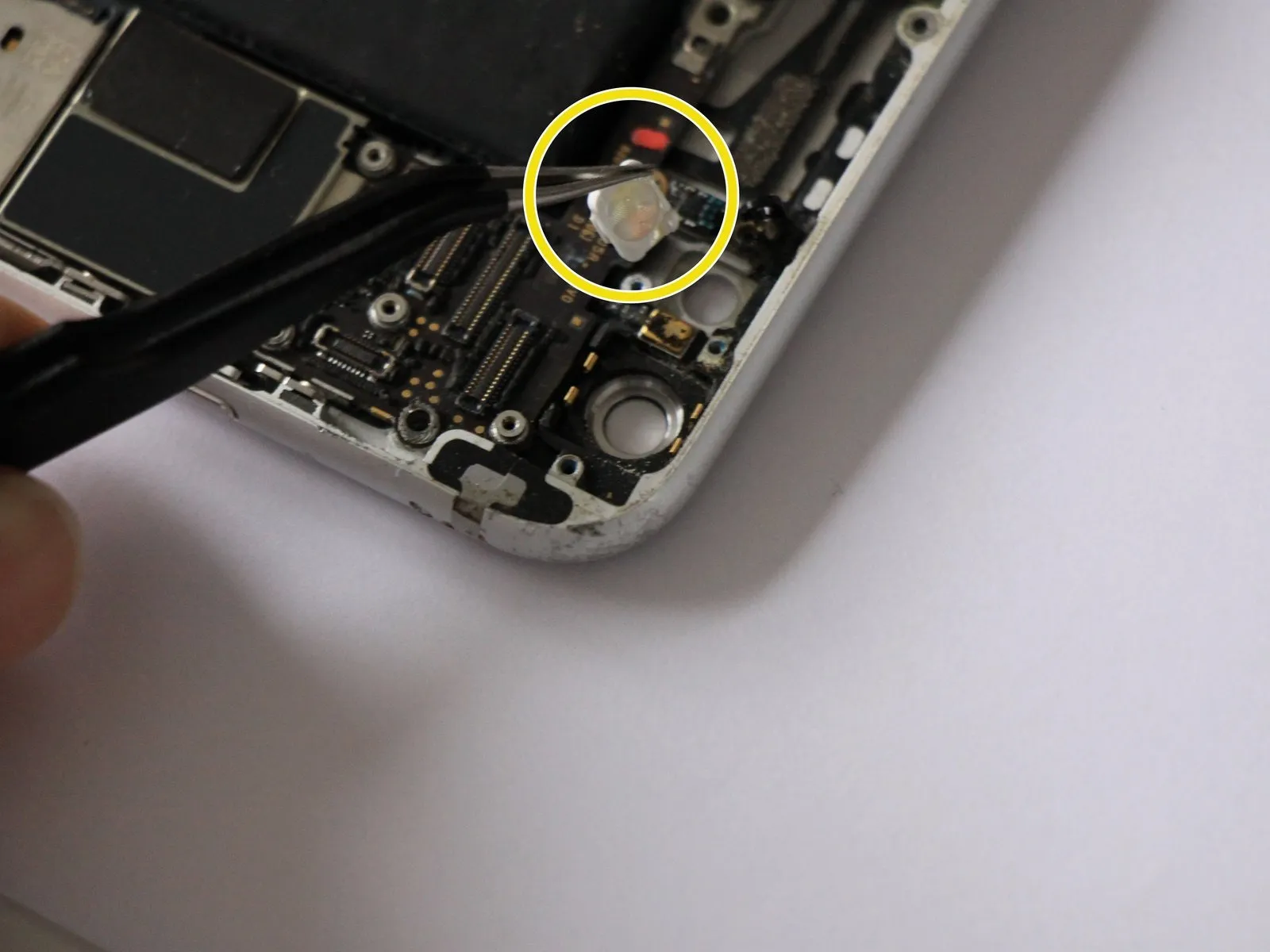
To address a common fragility in iPhone 5s repairs, the fingerprint sensor cable's path has been altered, significantly improving ease of access and reducing the risk of damage during disassembly, as the original design made the cable susceptible to tearing if handled improperly.
Due to the iPhone 6’s design, exterior components are secured with unique Pentalobe screws, necessitating the use of a specialized screwdriver for disassembly.
Due to Apple's policy, repair documentation and guidance for the iPhone 6 are unavailable to both authorized and non-authorized repair providers, as well as individual users.
Like previous iPhone 5 models, the display unit is detached as the initial step in the repair process, which streamlines screen replacements.
Accessing the battery is relatively simple; however, it necessitates a specialized pentalobe screwdriver and familiarity with adhesive release methods for removal, though the process itself isn't complex.
To address a common fragility in iPhone 5s repairs, the fingerprint sensor cable's path has been altered, significantly improving ease of access and reducing the risk of damage during disassembly, as the original design made the cable susceptible to tearing if handled improperly.
Due to the iPhone 6’s design, exterior components are secured with unique Pentalobe screws, necessitating the use of a specialized screwdriver for disassembly.
Due to Apple's policy, repair documentation and guidance for the iPhone 6 are unavailable to both authorized and non-authorized repair providers, as well as individual users.