iPhone 6s Home Button Assembly Replacement
Using the instructions provided, perform the necessary actions to substitute theThe component responsible for the device's primary navigation function is the home button assembly.Ensure all components are accounted for, with specific attention to measurements, numerical values, required tools, safety precautions, and designated part names.Employ a fresh sealing element to ensure a leak-free connection.Employing the specified tool, carefully connect the components while ensuring adherence to the precise measurement of 1.5 inches and observing all safety precautions regarding the part's designated number.Connect the wire, ensuring its length remains within the 12-inch specification, using appropriate crimping tools and observing all safety precautions regarding electrical shock.Carefully detach the battery connector from the logic board using a non-conductive spudger tool, noting its orientation for reassembly, as it is secured with a retaining clip.
- Using any replacement part voids the warranty, and only the phone's original charger should be utilized.The component responsible for the device's primary navigation and interaction is the home button assembly.The replacement home button enables standard home button operation; however, it does not replicate the Touch ID fingerprint scanning capability.
- This document serves as a resource for substituting theSupport structure for the home button..
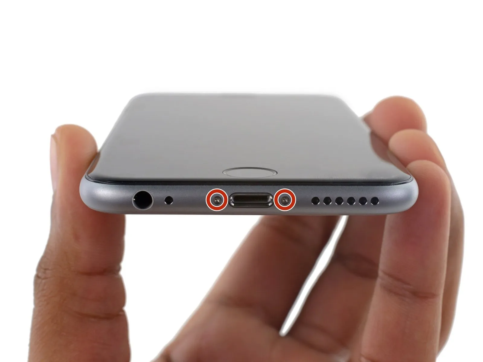
Step 1 | Pentalobe Screws
- To prevent potential hazards and damage, ensure the battery's charge level is reduced to less than 25% prior to beginning the disassembly process.A lithium-ion battery, already holding a full charge,Accidental puncture presents a fire and/or explosion hazard.
- To prevent electrical shock or damage, ensure the iPhone is completely de-energized prior to starting the repair process.
- Using a Pentalobe screwdriver compatible with 3.4 mm screws, detach the two screws located on the lower edge of the device, one on each side of the Lightning connector.
Step 2 | Anti-Clamp instructions


- To simplify the opening process, the following two steps utilize the Anti-Clamp tool, a custom design; if you do not have this tool, proceed to the steps three steps further down.
- Refer to the included guide for detailed procedures regarding the Anti-Clamp's operation.
- To release the Anti-Clamp's arms, move the blue handle in a rearward direction.
- Position the arms so they clear the left or right side of the iPhone, then move them into place.
- Affix two suction cups, one to the front and one to the rear of the iPhone, close to the lower edge, located directly above the home button.
- Apply vacuum by pressing the cups firmly against the surface you intend to work on.
- To improve the Anti-Clamp's grip if the iPhone's exterior feels excessively smooth, apply adhesive tape to the device's surface.
Step 3


- To secure the arms, advance the blue handle in the direction indicated.
- Rotate the handle fully, completing a 360-degree turn, observing for the initial expansion of the cups.
- Maintain parallel positioning of the suction cups; should misalignment occur, gently release the suction cups' hold and reposition the arms.
- Once sufficient separation is achieved by the Anti-Clamp, slide a prying tool beneath the display panel.
- To ensure adequate separation, reposition the handle by 90 degrees if the Anti-Clamp's opening is insufficient.
- To prevent damage, rotate the component no more than 90 degrees per increment, pausing briefly between each rotation to allow the Anti-Clamp device and dwell time to facilitate proper seating.
Step 4 | Opening Procedure
- Lacking an Anti-Clamp tool, proceed with the following three steps to utilize a suction handle.
- Using a hair dryer or iOpener, gently warm the bottom perimeter of the iPhone's casing with moderate heat for approximately 60 seconds.
- Applying heat will loosen the adhesive that holds the display in place, simplifying the opening process.
Step 5
- To access the 6s display, carefully release the adhesive strip encircling its edges; replacement adhesive strips should be prepared beforehand if desired. Completing the repair without fresh adhesive is feasible and unlikely to affect device operation.
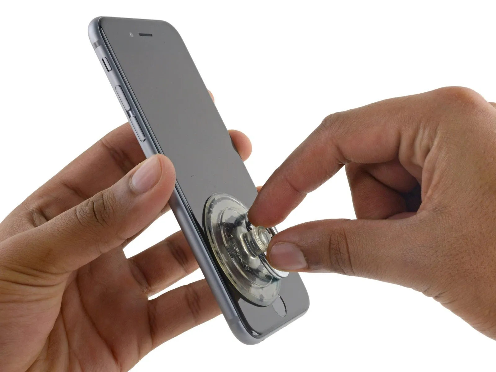
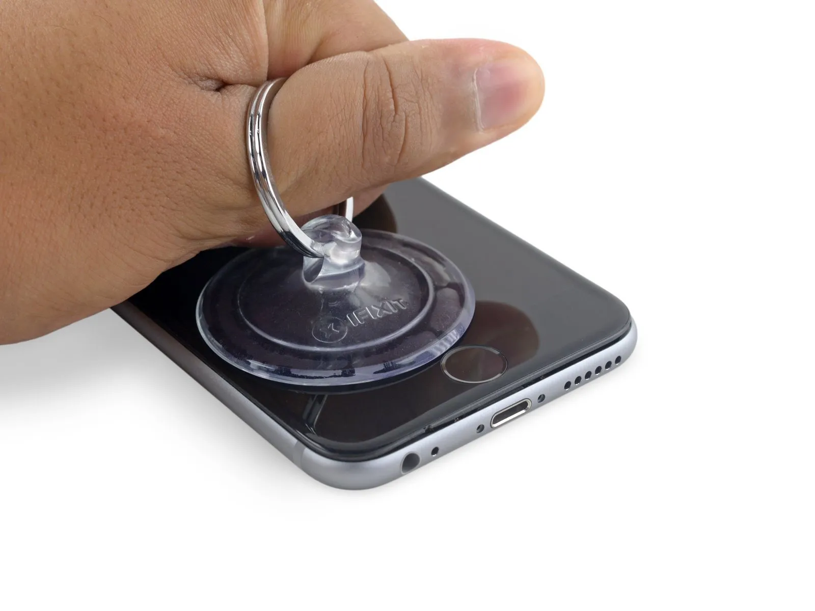
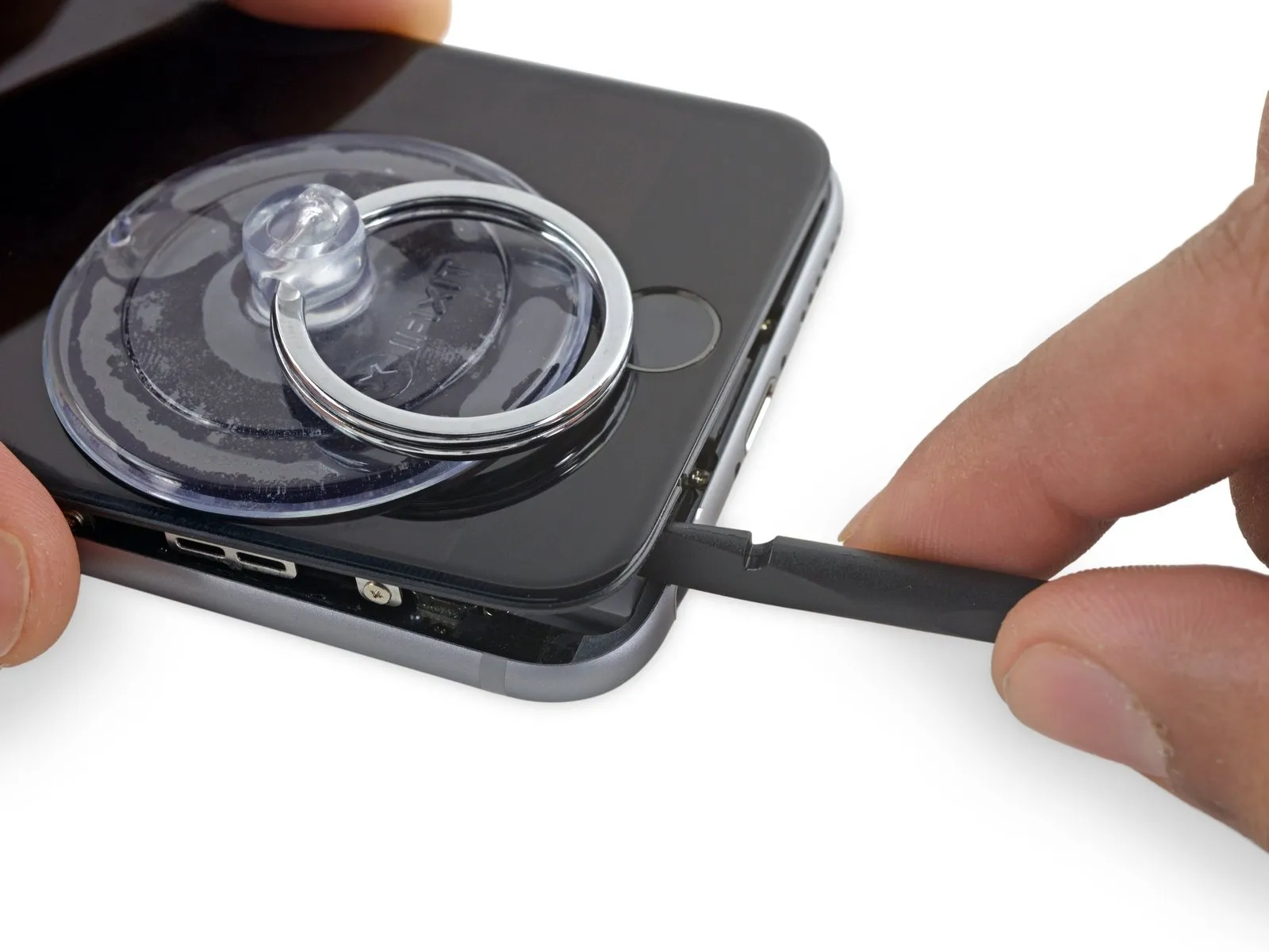
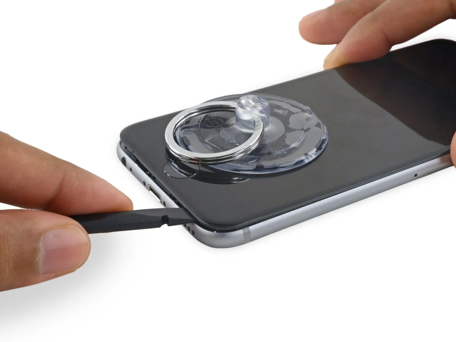
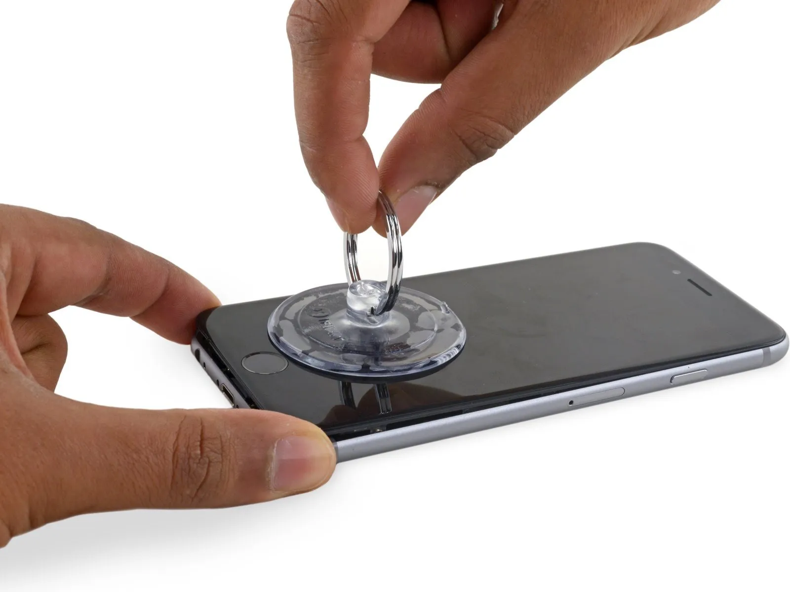
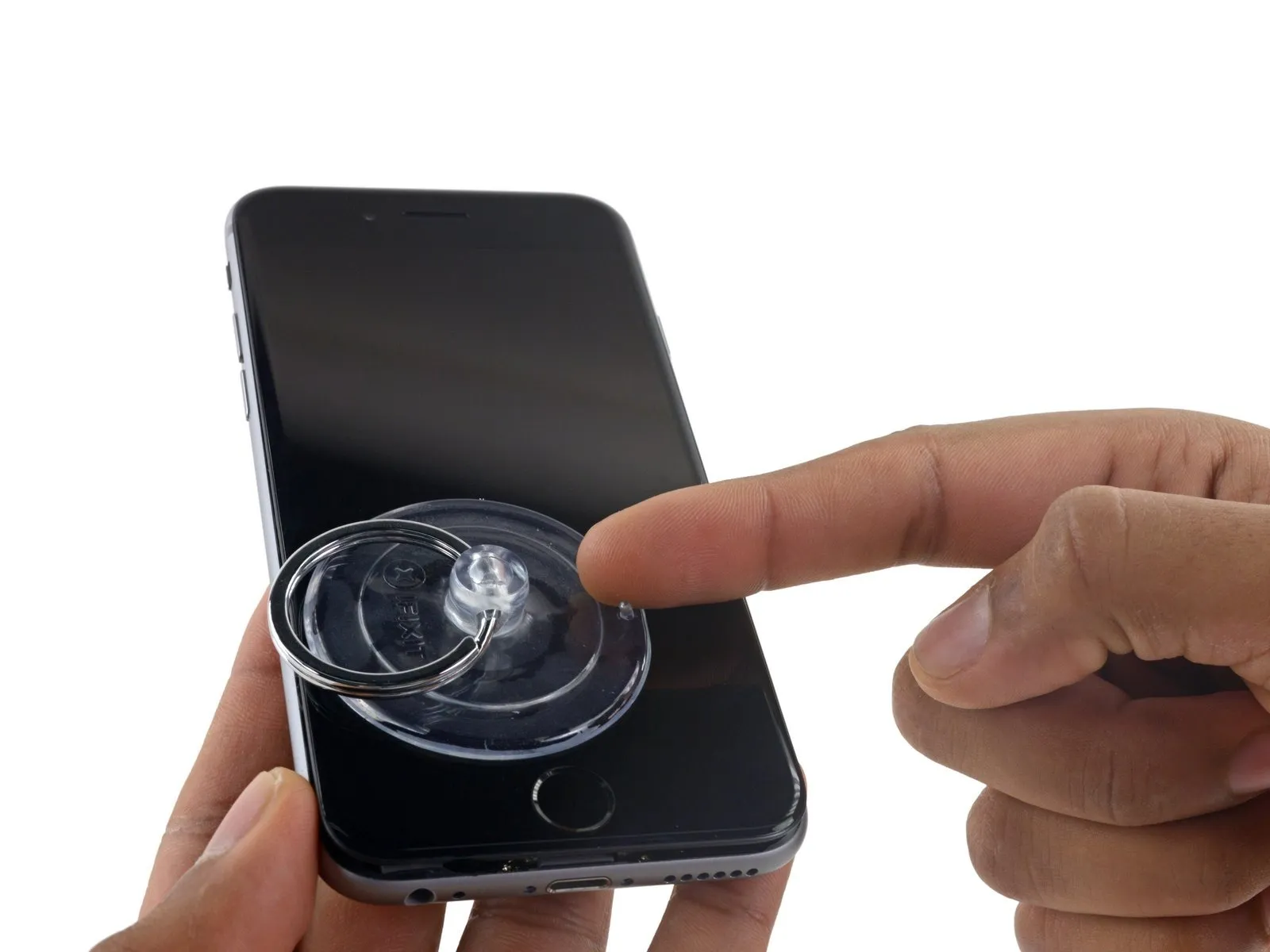
- Securely attach a suction cup to the display assembly's lower-left corner.
- Avoid positioning the suction cup directly on the home button.
- To facilitate suction cup attachment when the display has severe cracking, apply a sheet of clear packing tape across the damaged area; otherwise, a robust adhesive tape can serve as a substitute for the suction cup. As a last resort, secure the suction cup directly to the fractured screen using superglue.
Step 6
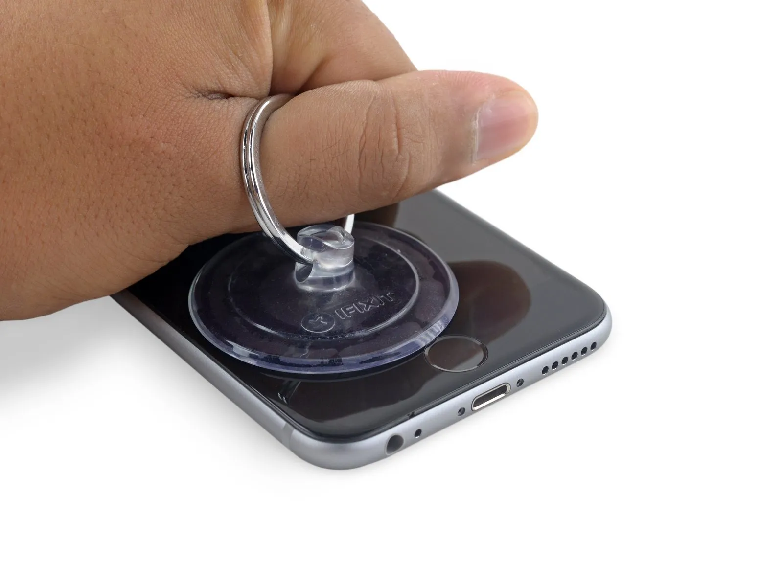
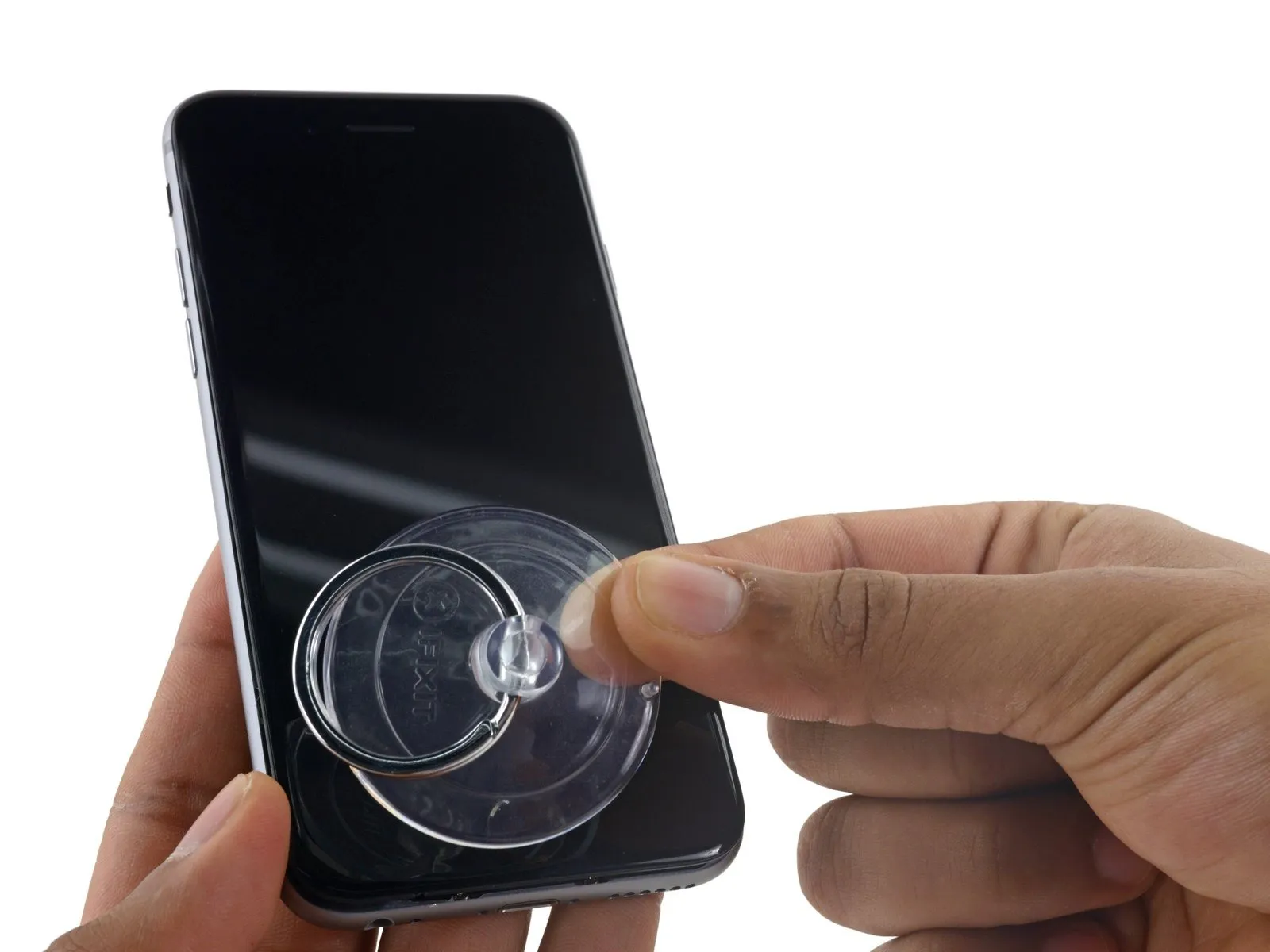
- Apply steady, even force to lift the suction cup, generating a small separation between the front panel and the rear case.
- Exercise caution and use steady, even pressure during installation; the display unit’s fit is significantly snugger than typical device components and secured with adhesive.
- To prevent display assembly damage, use only the minimal force needed to separate the display assembly from the rear case, creating a slight space.
- To ease separation of the display from the frame, apply warmth to the front of the device with an iOpener, hair dryer, or heat gun until the surface reaches a temperature that is uncomfortably warm to the touch. This process loosens the adhesive that holds the display's perimeter in place.
Step 7
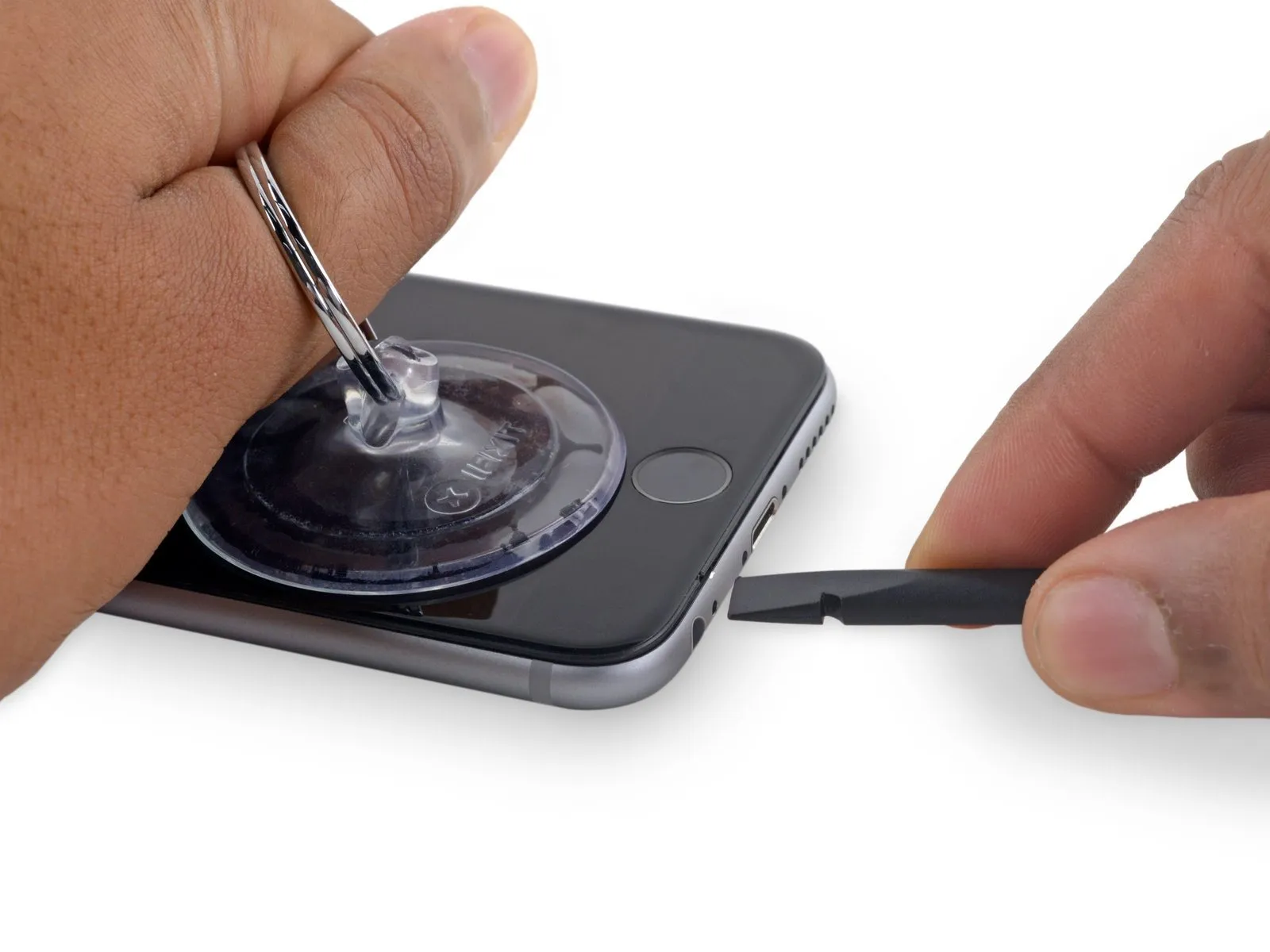
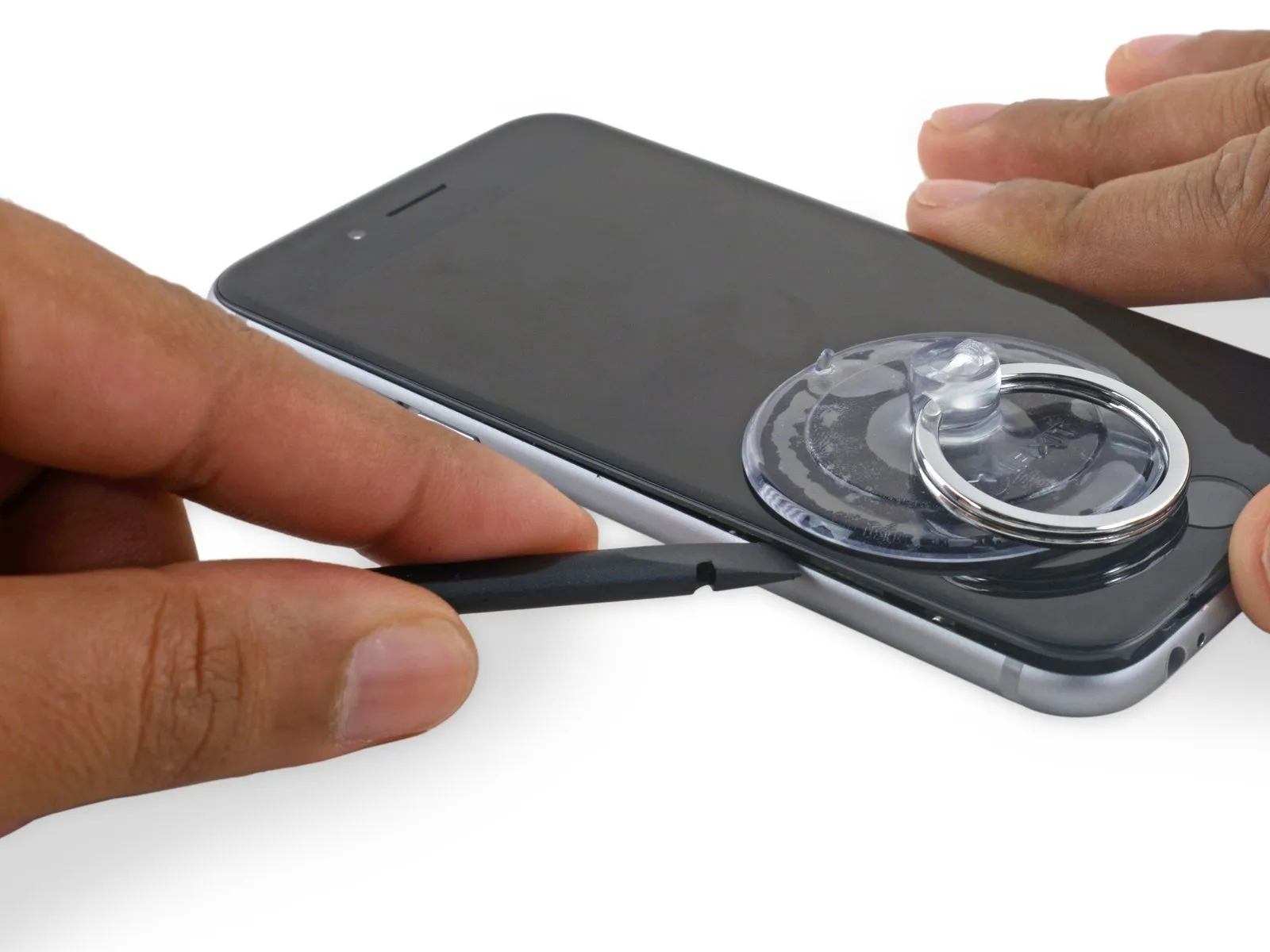
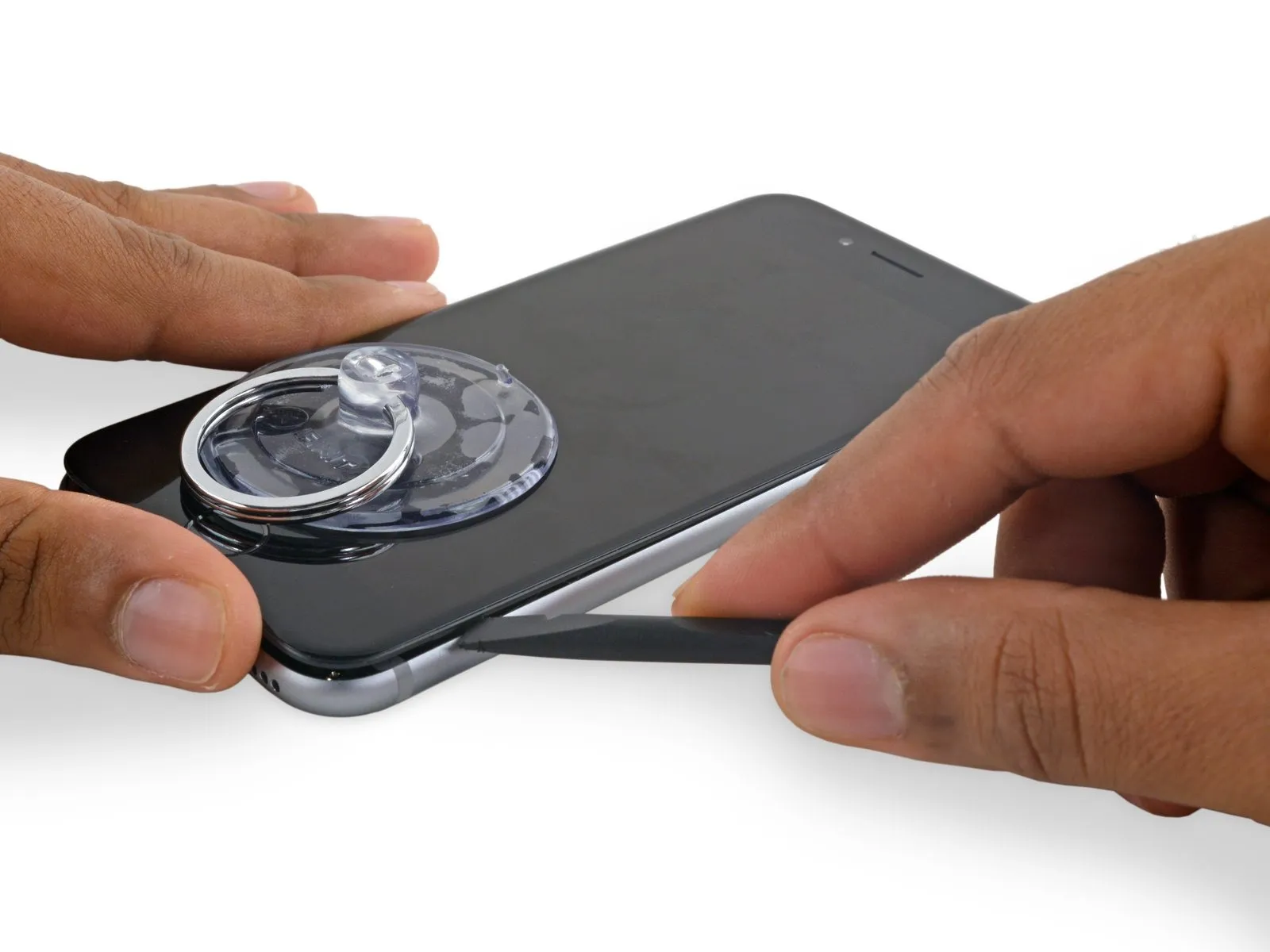
- To initiate separation of the device housing, insert a plastic opening tool into the recess located on the display's lower surface, directly above the headphone jack; this area provides the most secure starting point to prevent damage.
- Using a spudger, insert its flat side into the separation between the display and the back cover, positioning the insertion point immediately over the headphone jack.
Step 8
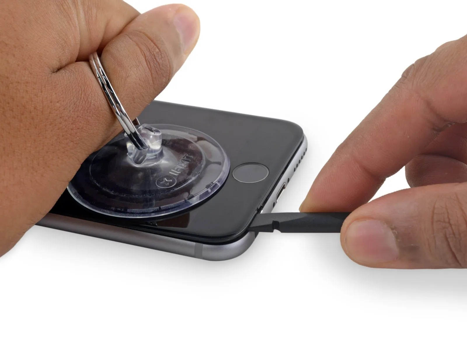
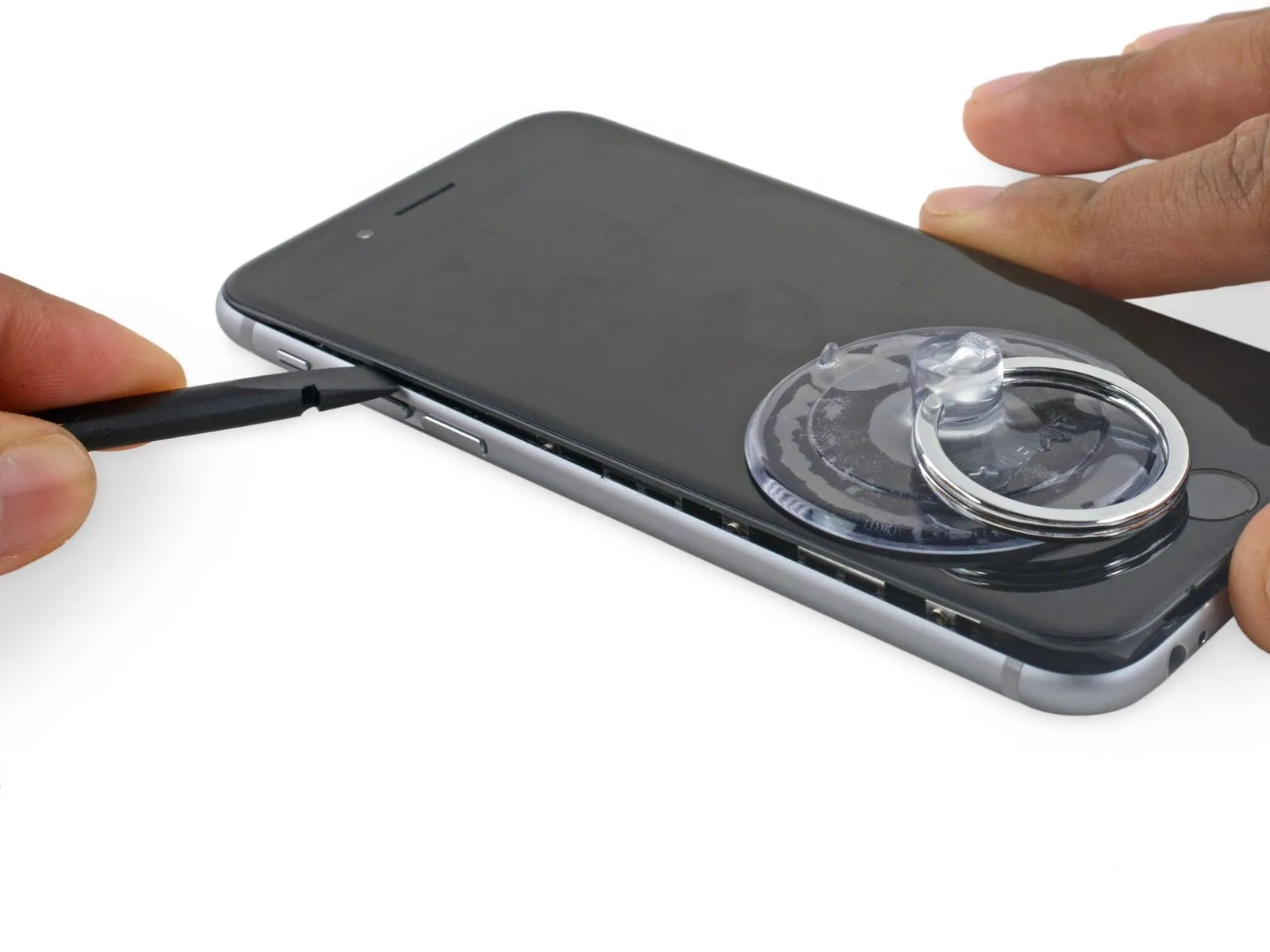
- Using a spudger, gently increase the separation between the front panel assembly and the phone's main body.
Step 9
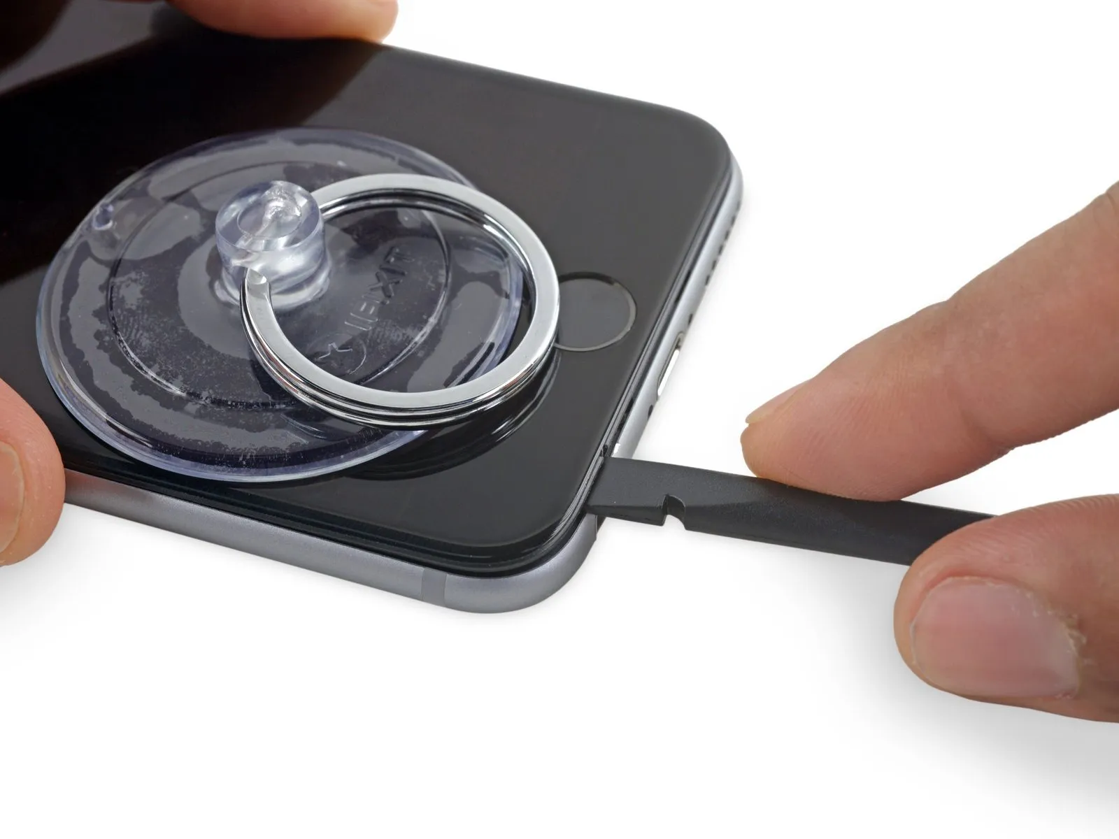
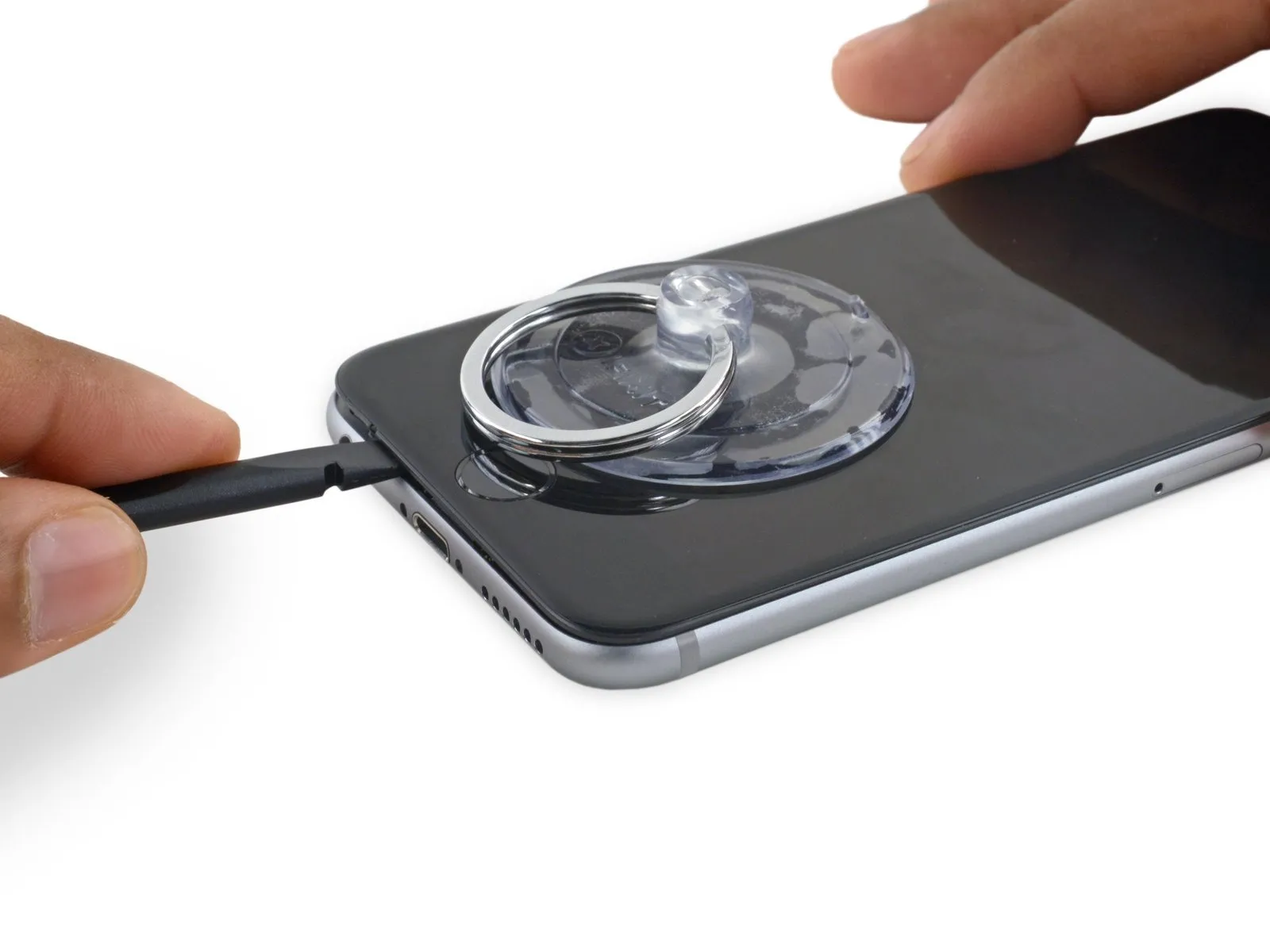
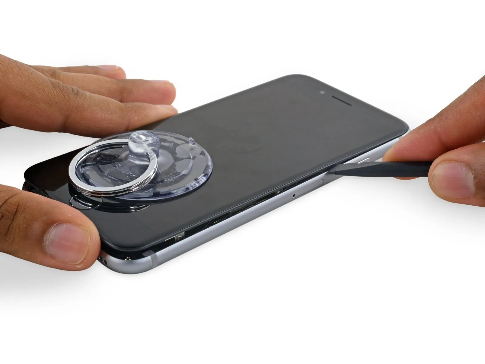
- Using the tool's straight edge, carefully slide it into the designated space.Use a plastic pry tool, often referred to as a spudger.Locate the component on the device's left lateral surface, positioned in the space separating the display assembly and the rear case.
- Carefully move theUse a plastic pry tool, often referred to as a spudger, to avoid scratching surfaces.Carefully lift the phone's side to release the adhesive and disengage the retaining clips.
Step 10
- Carefully detach the component, ensuring no damage occurs.Use a plastic pry tool, often referred to as a spudger, to carefully separate components.Carefully align the component with its original position at the lower edge of the device, the area previously accessed by separating the housing.
- Carefully move theUse a plastic pry tool to gently separate.Locate the edge of the device at the base, on its right-hand side.
Step 11
- Carefully move theUse a plastic pry tool, often referred to as a spudger.Proceed along the right edge, carefully releasing the adhesive bond and disengaging the display clips from their securing points on the iPhone.
Step 12

- Employ the specified tool to carefully manipulate the component, ensuring a torque of 3.2 Newton-meters is applied, and observe the safety precautions regarding potential pinch points.Employ a vacuum-creating device to establish a secure hold.Carefully separate the display assembly from the device housing by releasing the remaining adhesive bond.
- To prevent damage to the three cables securing the display at the top, limit its opening angle to a maximum of 90 degrees.
Step 13
Step 14
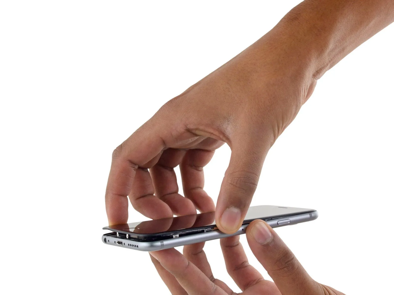
- Employing a careful grip, raise the display assembly, leveraging the front panel's top clips to act as a pivot point and separate the device.
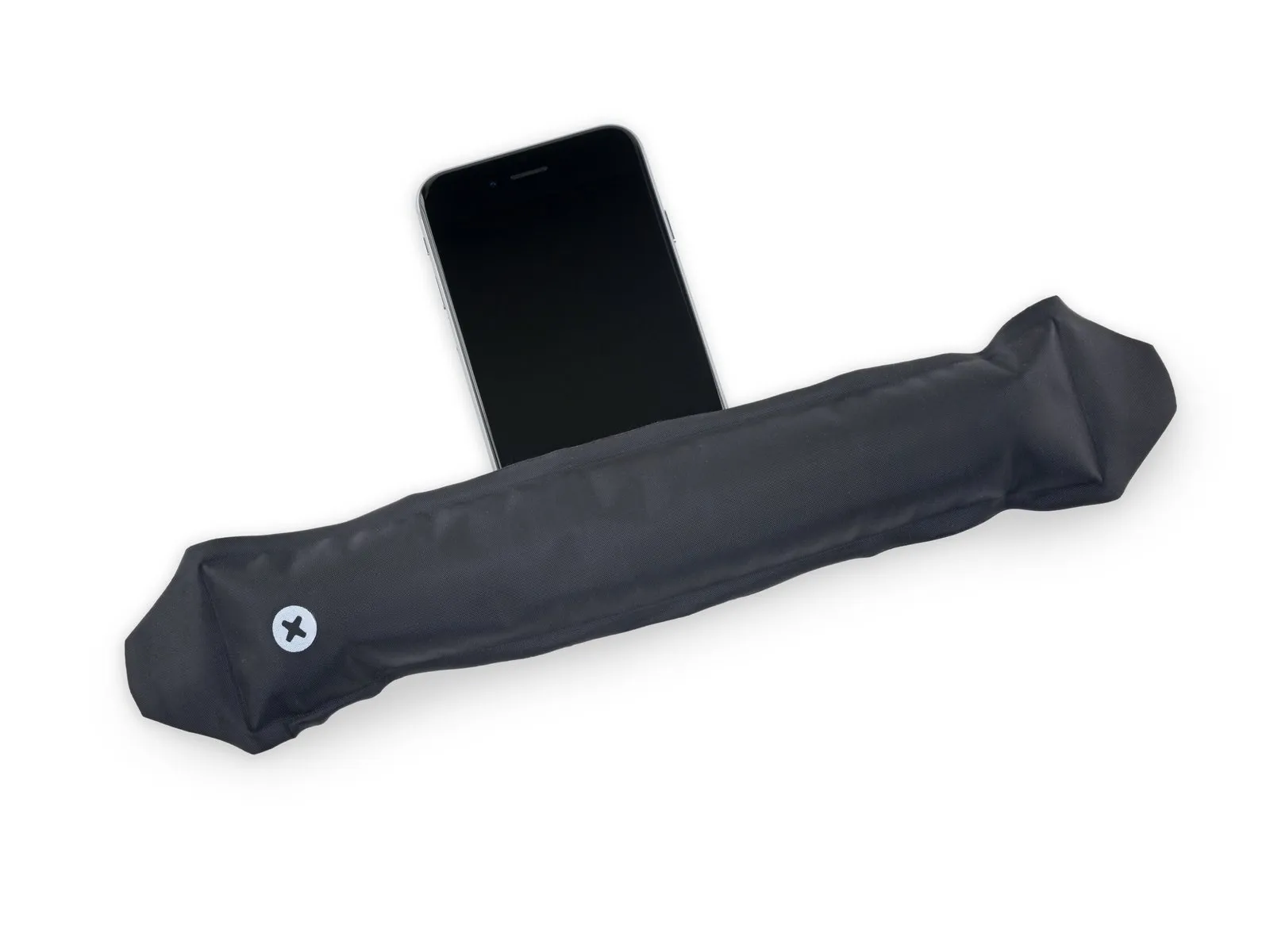
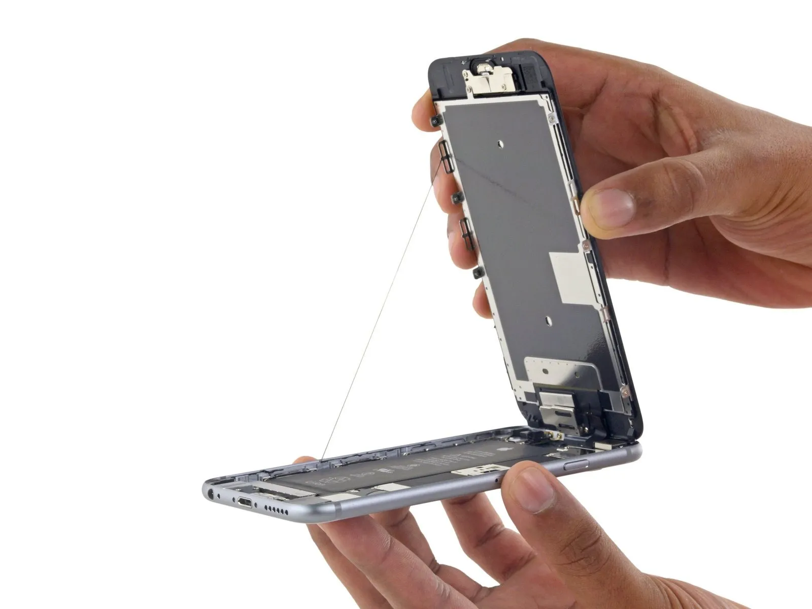
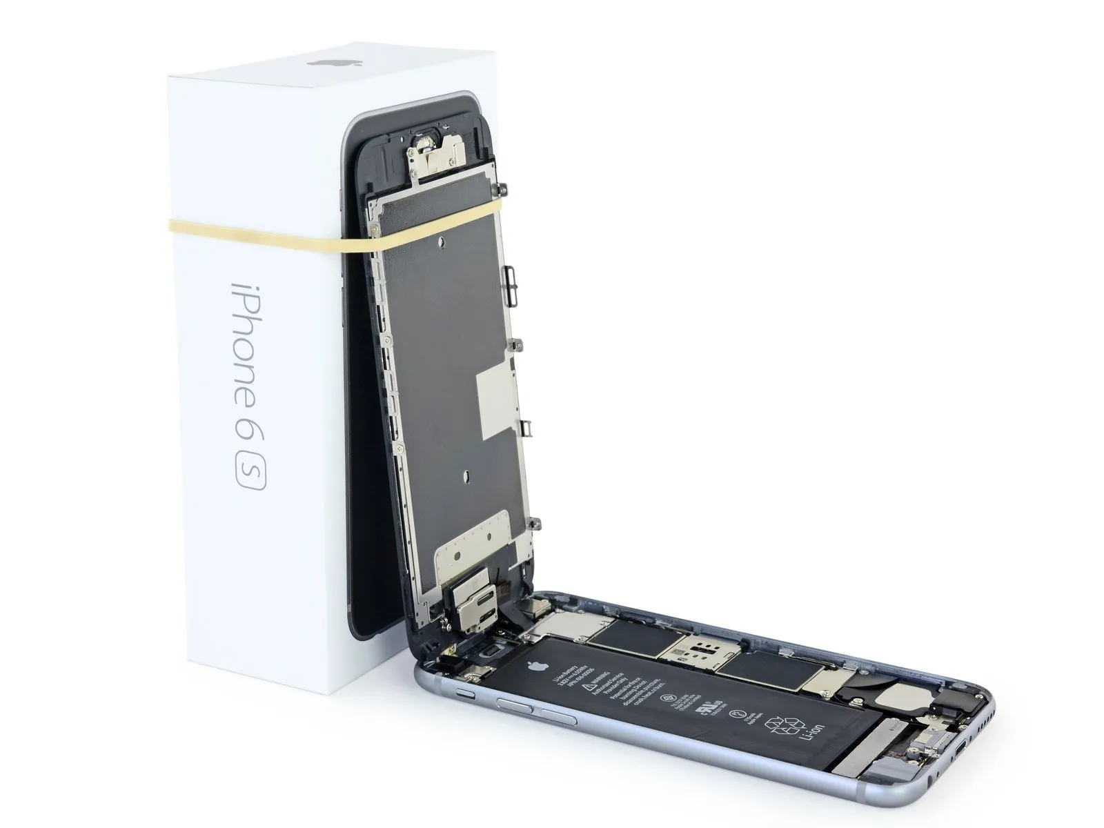
- Carefully position the display at a 90-degree angle, then secure it in an upright position using a support to prevent movement during the repair process.
- To avoid stressing the display's wiring during the repair process, secure it with a rubber band.
- As a temporary substitute, an unused, sealed can of soda can be employed to support the screen.
- If you intend to substitute fresh adhesive along the display's perimeter during reassembly, stop at this point.
- To facilitate cover closure and ensure proper clipping, during reassembly, guide the camera-side edge of the screen body beneath the main body's edge, positioning the screen frame hooks beneath the main body's rim and drawing them taut in the direction of the camera end.
- Ensure these clasps, which function as a substitute for a hinge, are positioned correctly beneath the phone's outer frame edge; this placement allows the screen to smoothly and softly return to its closed position, engaging with a gentle snap.
- To reinstall the screen, begin by applying pressure to secure the upper right corner, working downwards along the edge, followed by the upper left corner.
Step 15 | Battery Connector
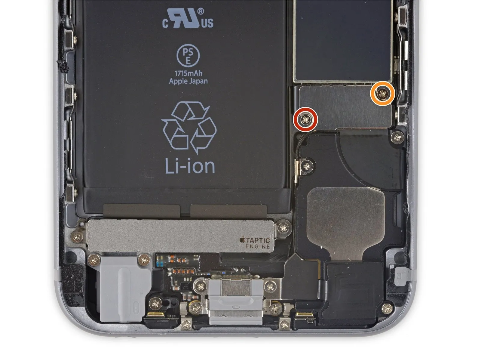
- Using a Phillips screwdriver, detach the two screws—each measuring the same length—that hold the battery connector bracket in place.
Utilize a 2.9 mm screw for installation.
Utilize a 2.2 mm screw for this step.
Step 16
Step 17

Step 18
Step 19 | Unfasten the display cable bracket
- Carefully detach the quantity of four specified components.Use a Phillips head screwdriver.Using a 3mm hex key, tighten the bracket that holds the display cable to the chassis, ensuring screws are snug but not over-torqued to prevent damage.
- Use a quantity of three.Use screws with a diameter of 1.2 millimeters.
- Begin the process by executing the action designated as "one."Use a 2.8-millimeter screw.
Step 20
Step 21
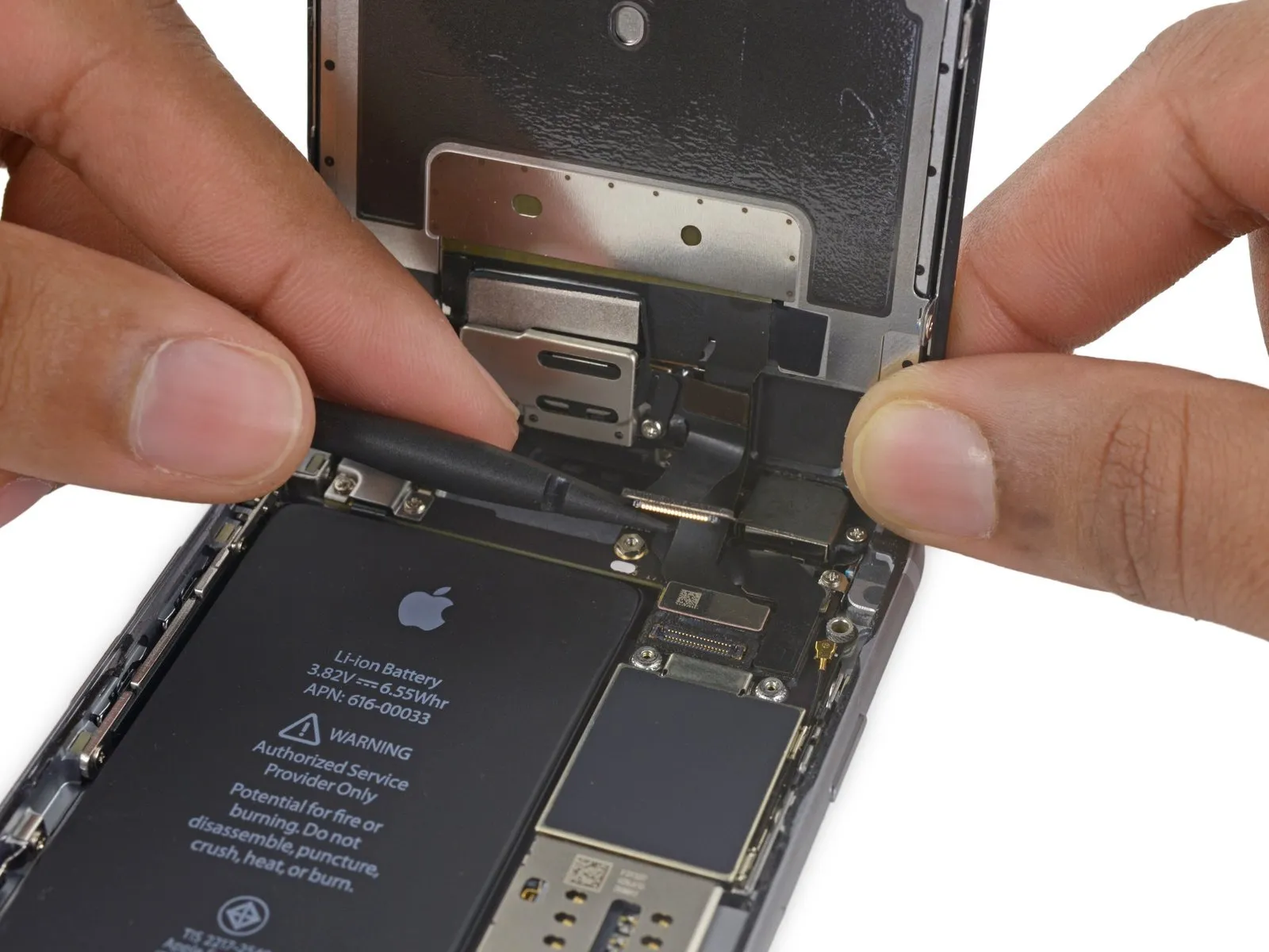
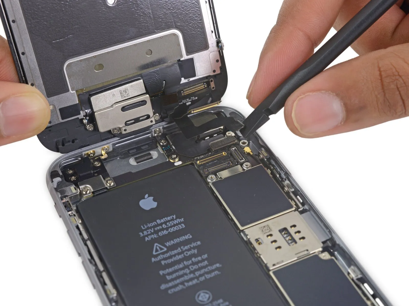
- Employ a 3/8-inch socket wrench to loosen the retaining bolt to 15 Nm, then carefully detach the component, observing the cautionary note regarding potential spring tension.Use a plastic pry tool, often referred to as a spudger.Ensure the surface is free from any contaminants.Use a fingernail.Using a prying tool, carefully lift the front camera flex cable directly upward to release it from its connector on the logic board.
Step 22
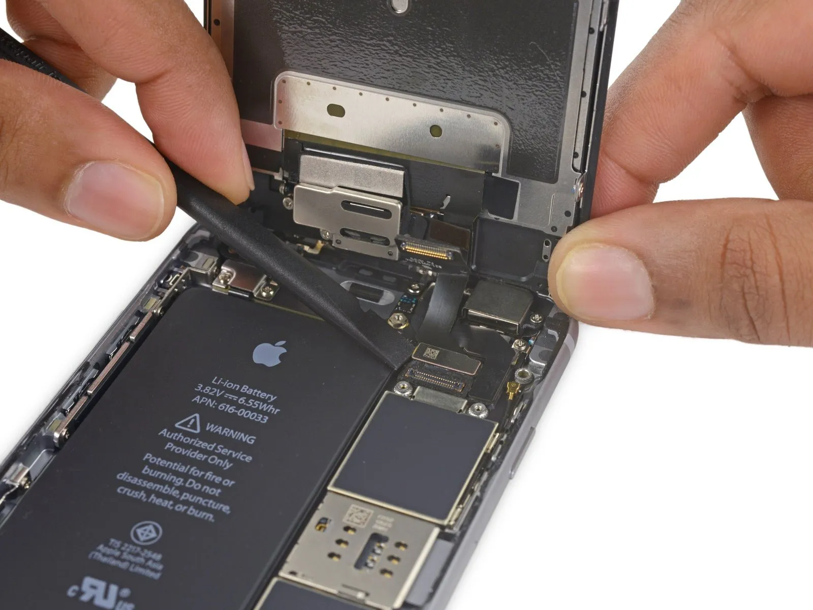
- Using a prying tool, carefully separate the digitizer cable from its connection on the logic board by applying upward force.
- To ensure proper alignment and prevent damage, apply pressure to opposing ends of the digitizer cable connector during reconnection; avoid central pressure, as this may warp the component.Inspect the display assembly for cracks, delamination, or other physical imperfections affecting the touch-sensitive layer, noting any areas where the digitizer's responsiveness is compromised..
Step 23
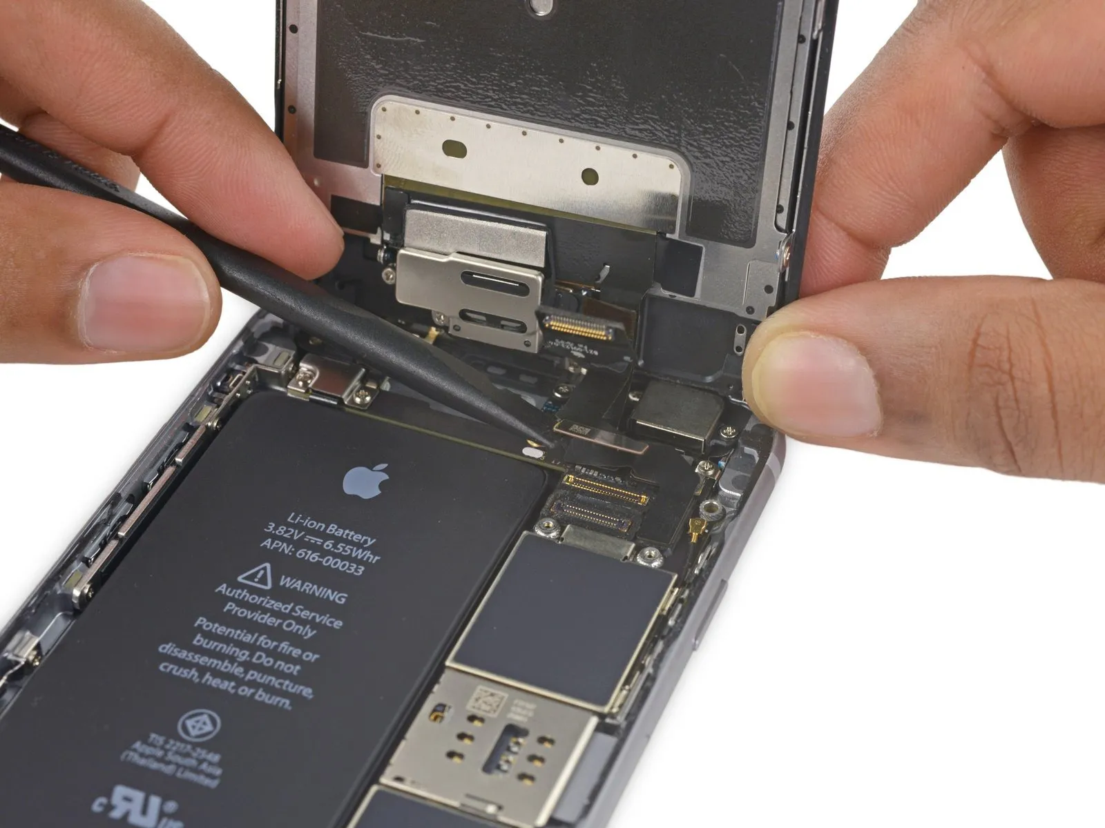
- Prior to either detaching or reattaching the cable in this procedure, ensure the battery is disconnected.
- Using a suitable tool, carefully release the display cable's connection by applying upward pressure directly to its connector on the logic board.
Step 24
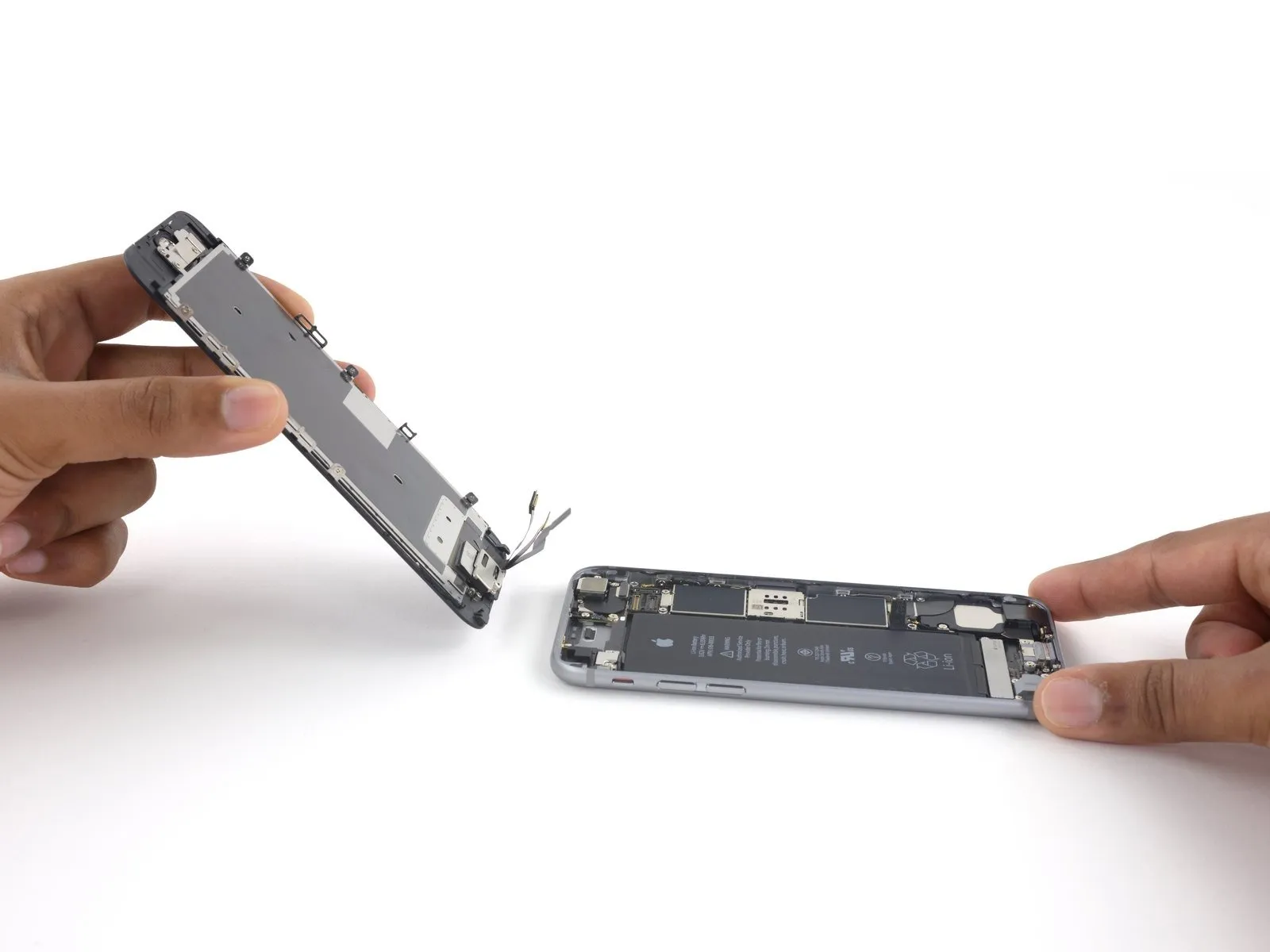
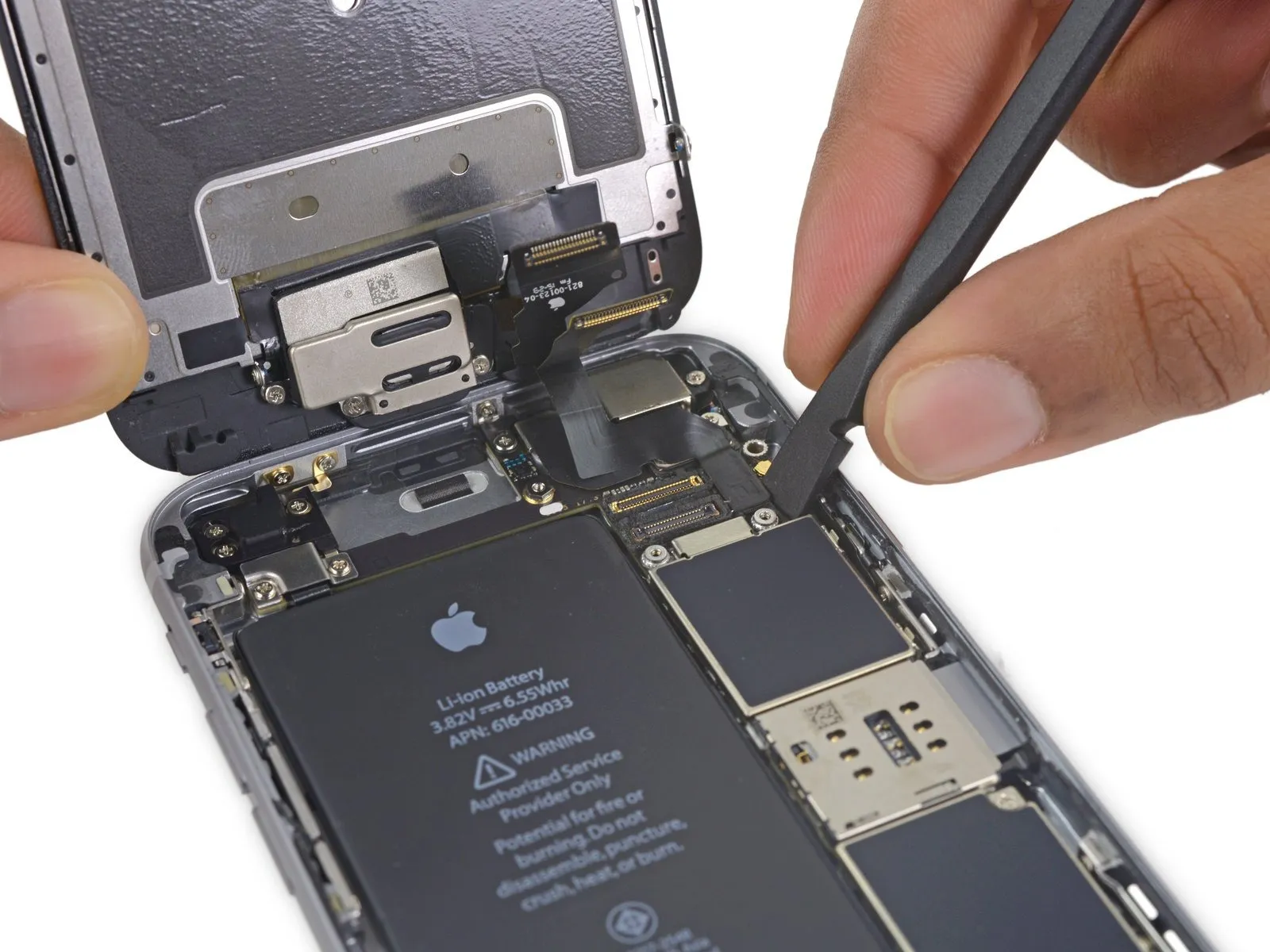
- Carefully detach the display assembly, ensuring no damage occurs.
- If you intend to renew the perimeter adhesive seal on the display during reassembly, stop at this point.
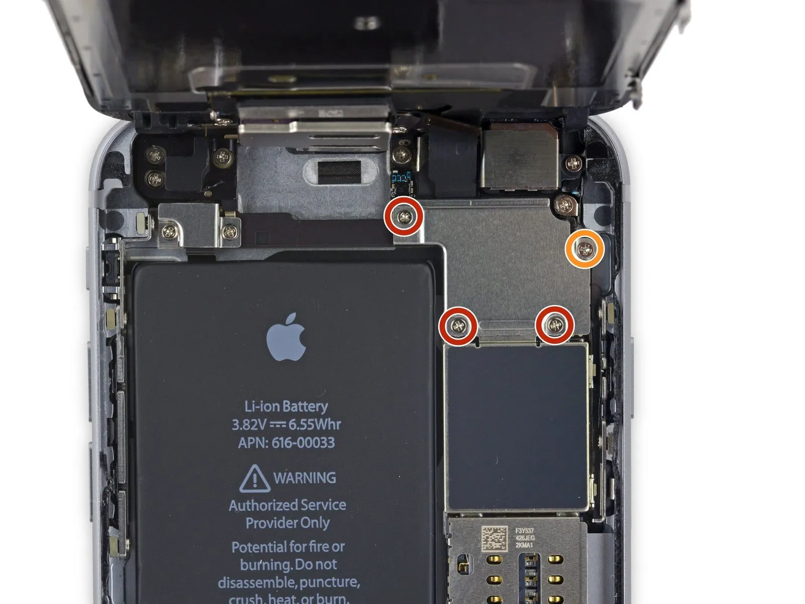
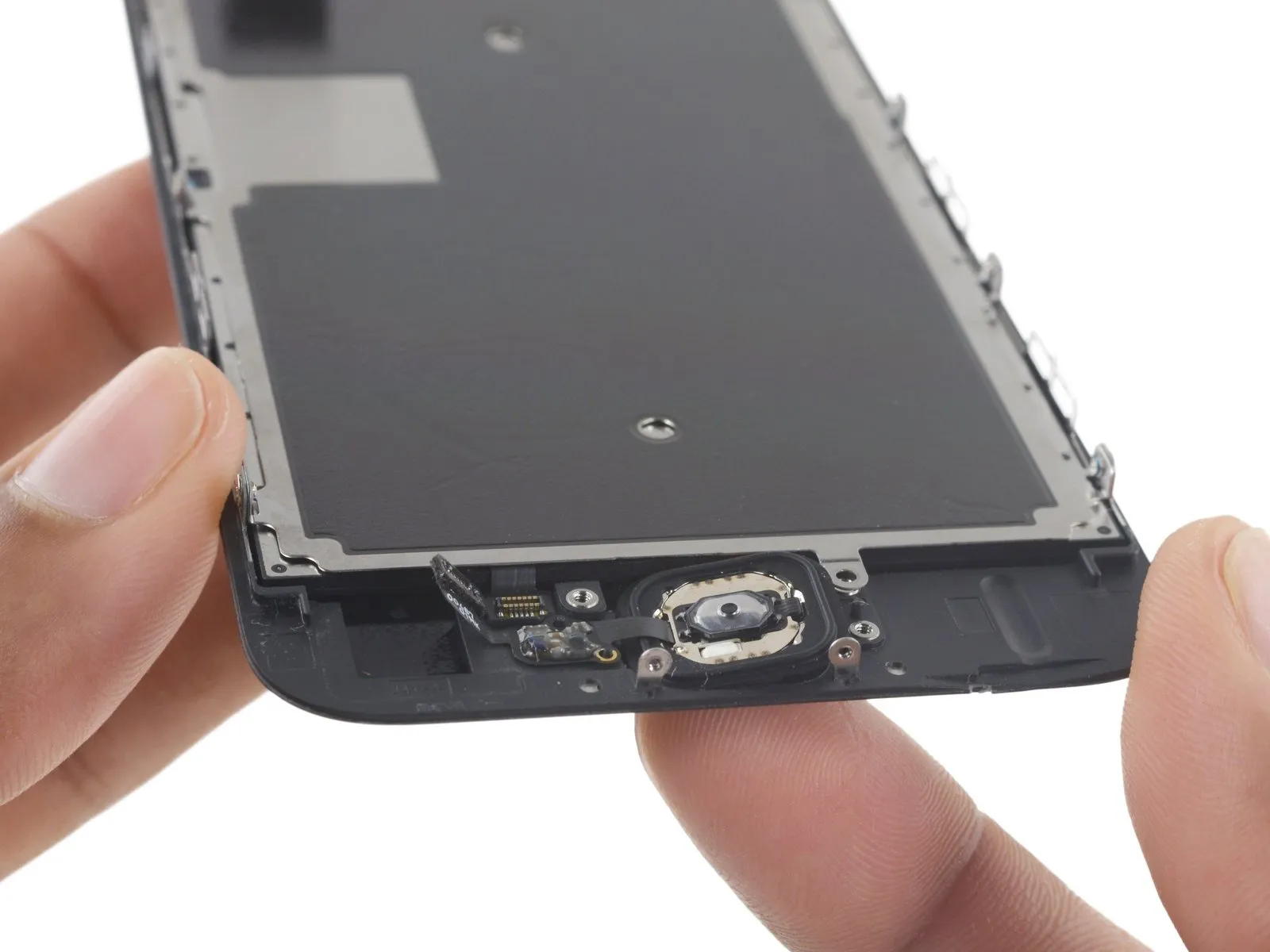
Step 25 | Home Button Assembly
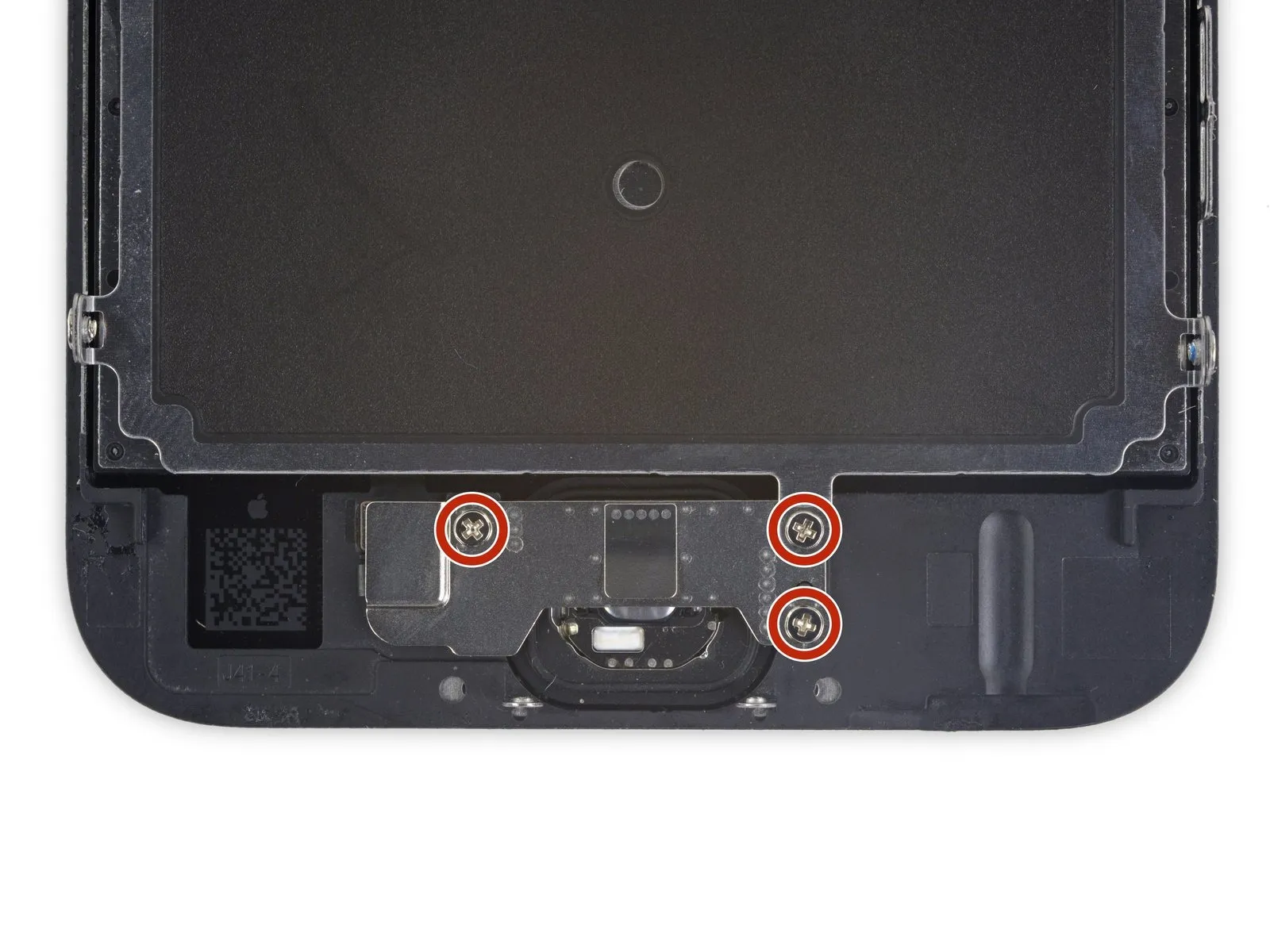
- Using the appropriate tool, detach the three screws.Use a Phillips screwdriver with a 1.7 mm tip.Ensure the home button bracket is firmly affixed.
- Applying excessive force when tightening these screws risks damaging the display's front surface.
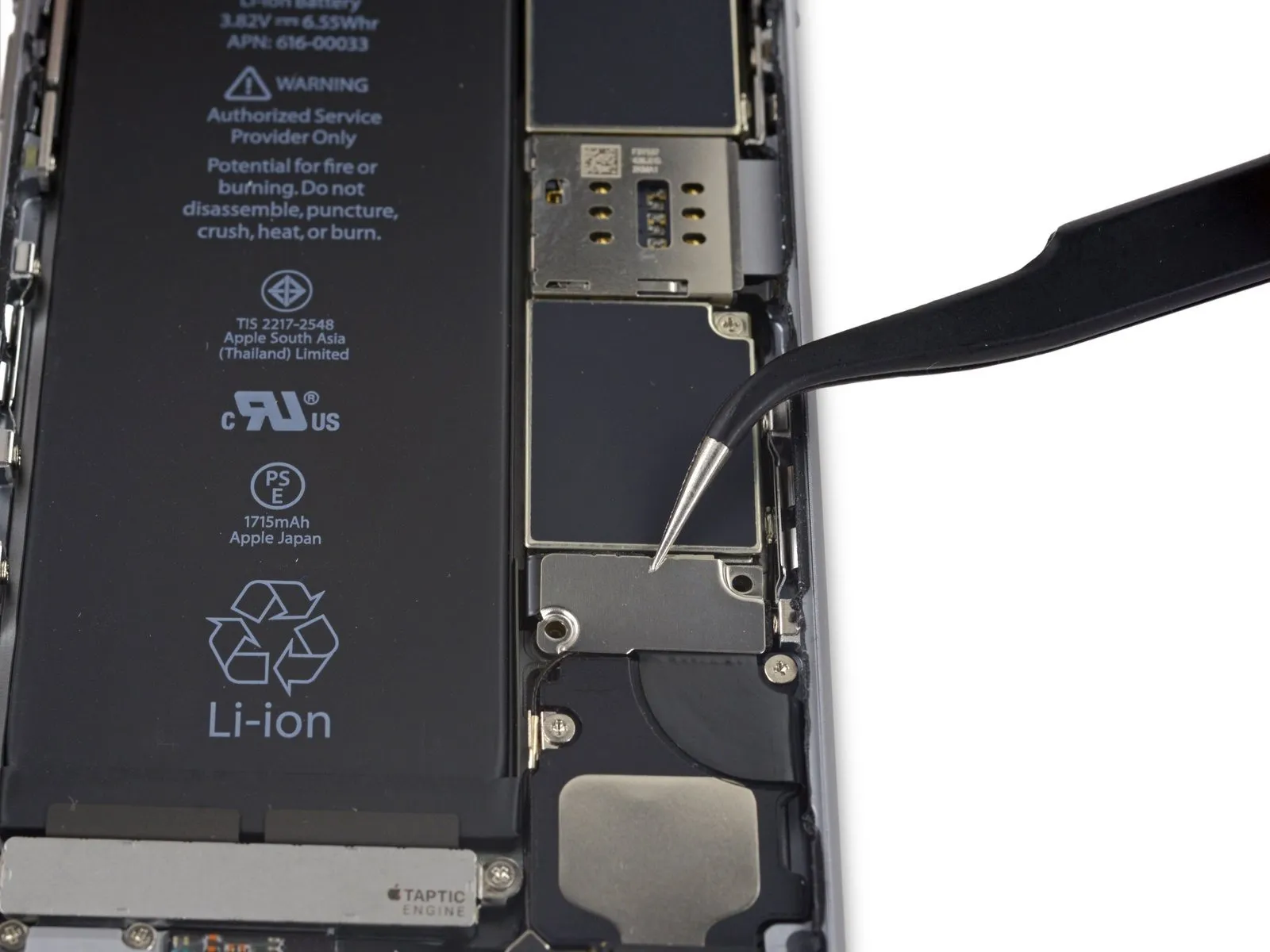
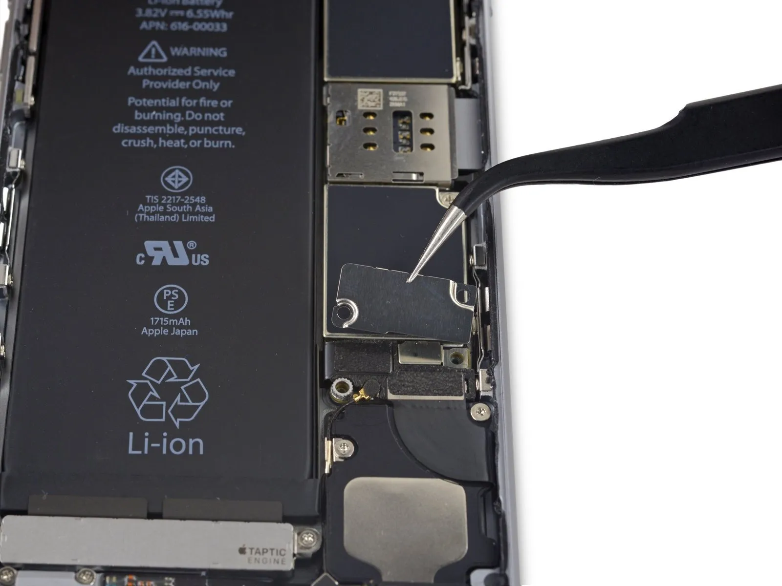
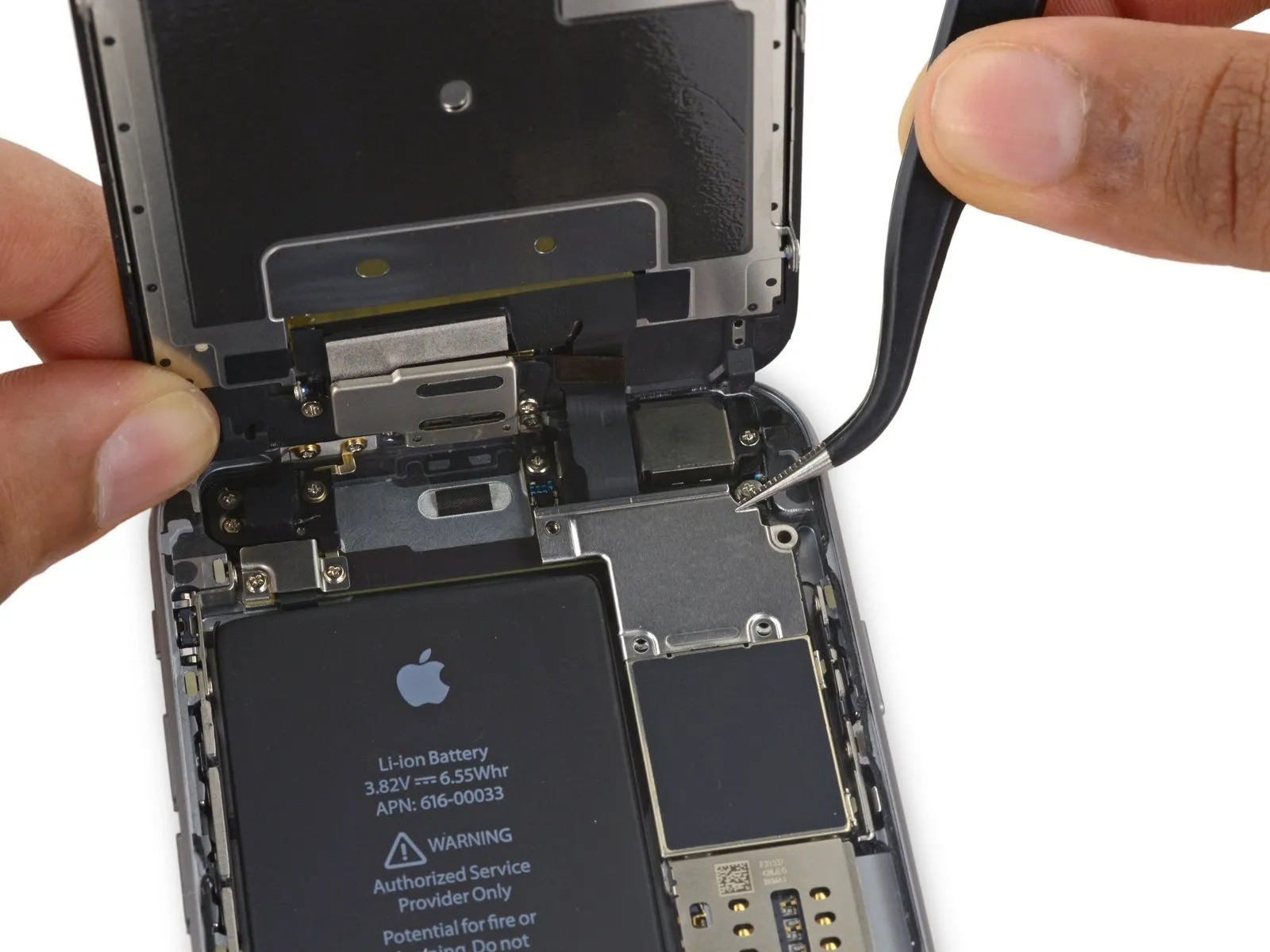
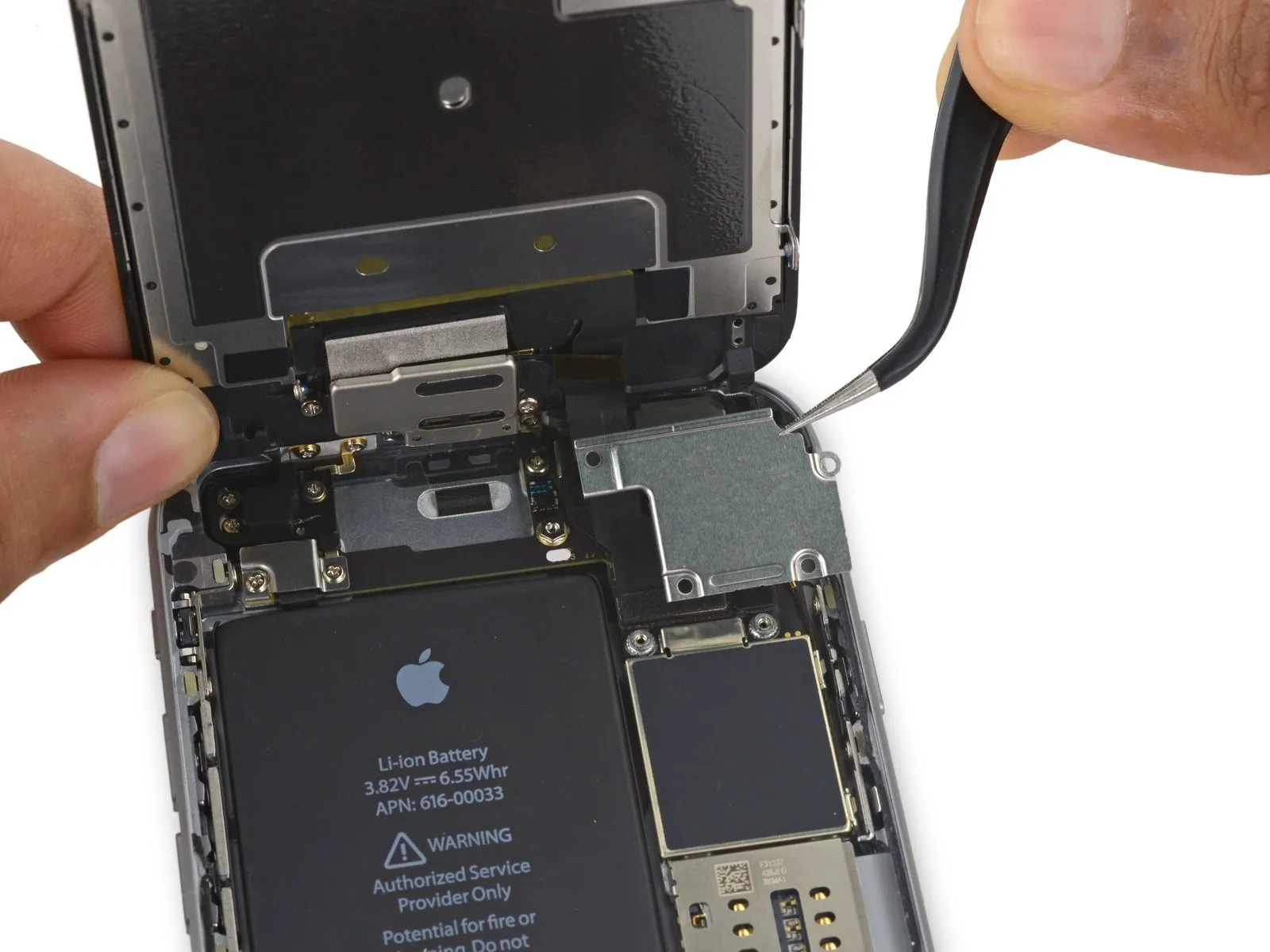
Step 26
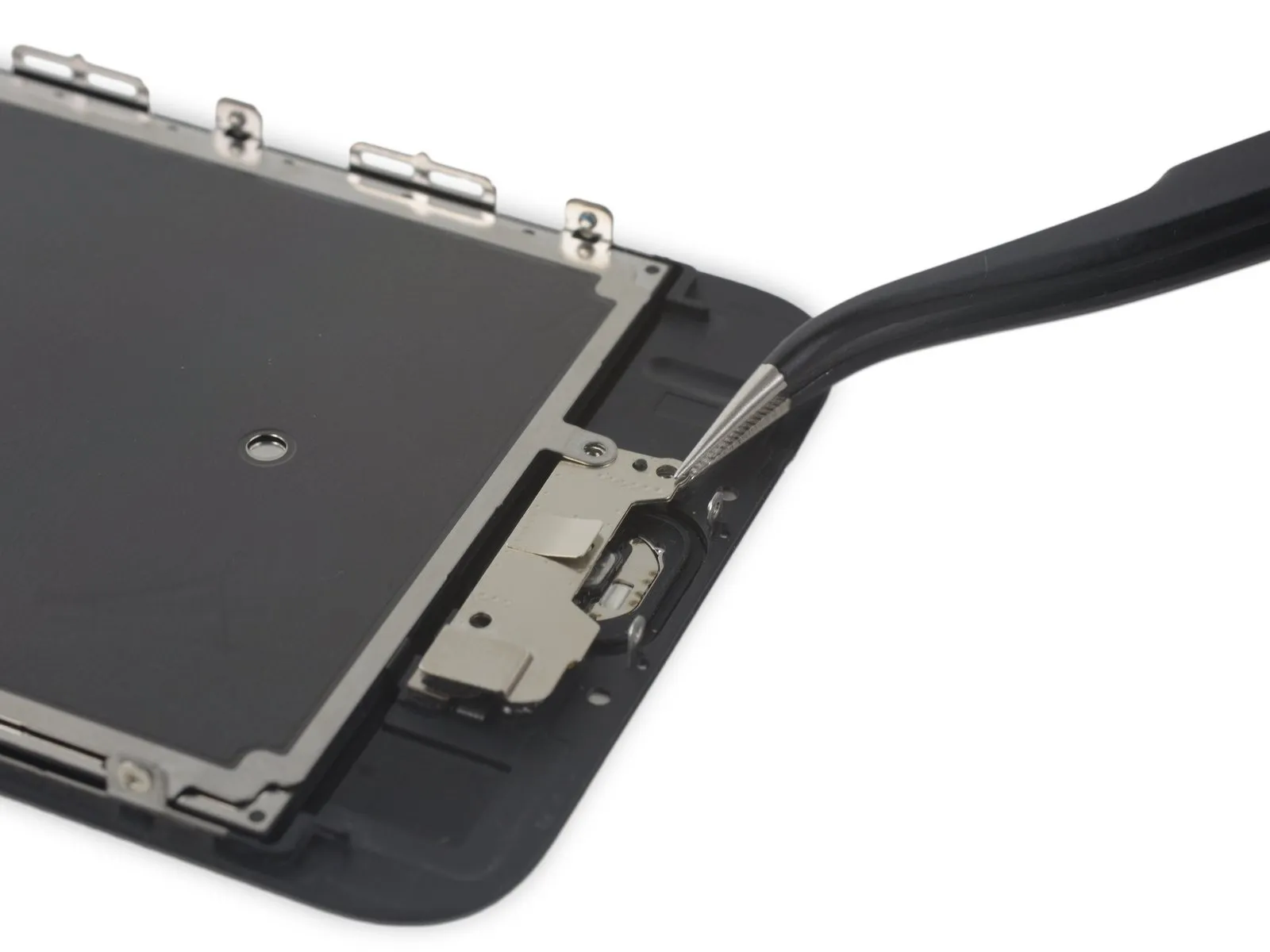
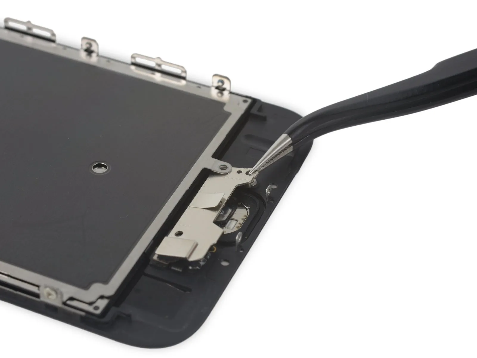
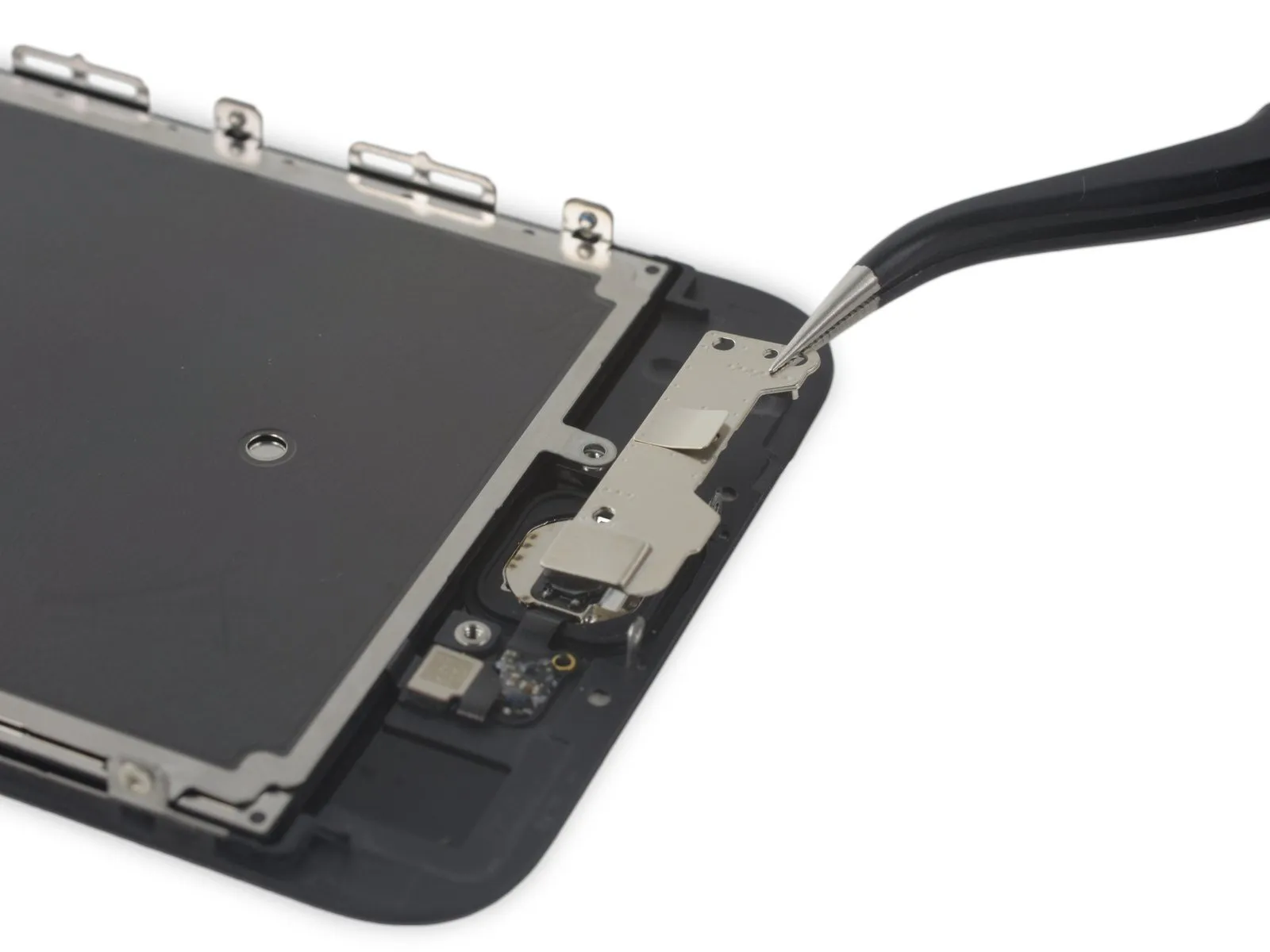
- Carefully raise the lower portion of the home button bracket, ensuring it disengages from the retaining pin located on the right-hand side.
- To detach the EMI shield, carefully extract the bracket that secures it from its position beneath.
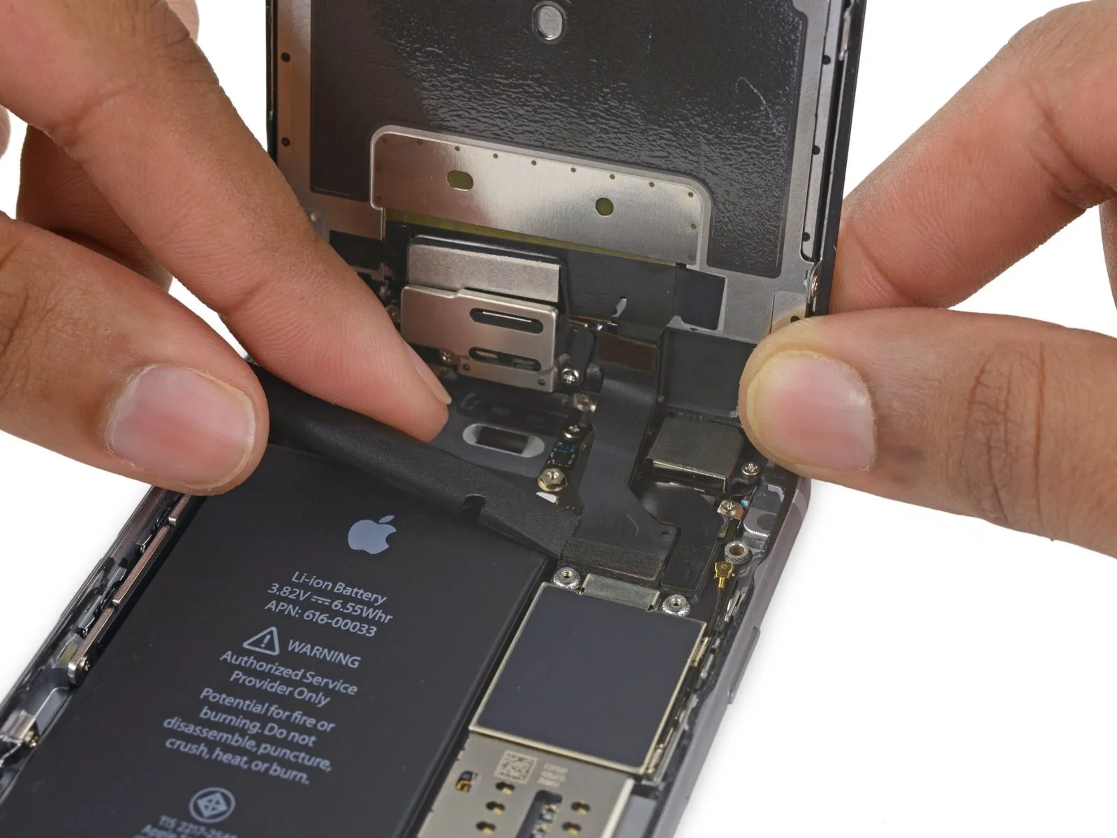
Step 27
Step 28

- Due to its delicate nature, the thin rubber gasket that seals the home button is prone to tearing.
- Use a heat gun or hairdryer set to a low setting to gently warm the component.Use a specialized iOpener tool.,Apply warmth with a device capable of generating controlled heat.Using a 5/32-inch hex key, carefully tighten the retaining screw to a torque of 4.5 Nm, ensuring you do not overtighten and damage the threads.Utilize a device designed to emit warm, directed airflow, ensuring the unit's wattage is no greater than 1500W and its cord is undamaged, to gently warm the component.Apply a solvent to loosen the adhesive that holds the home button gasket in place.
- Apply steady, upward force to the home button via the display assembly's front surface, employing your fingertip to carefully detach the rubber gasket from the front panel.
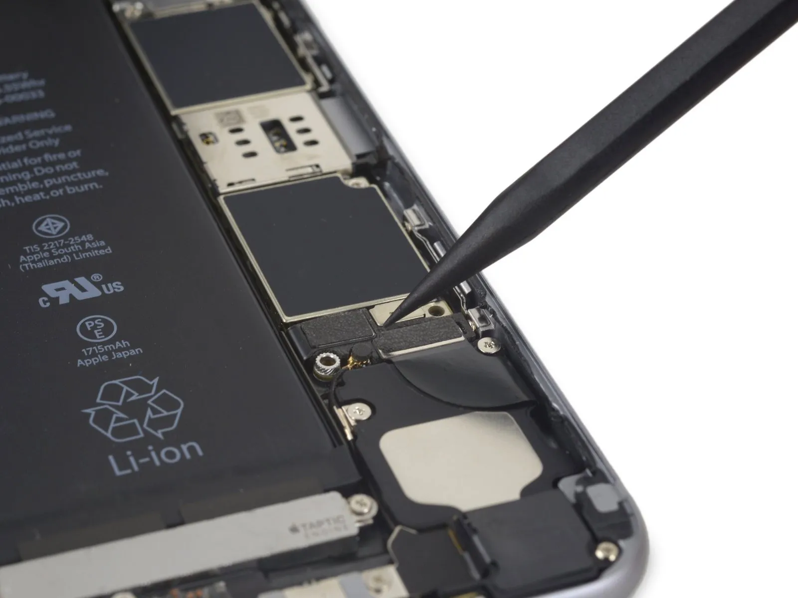
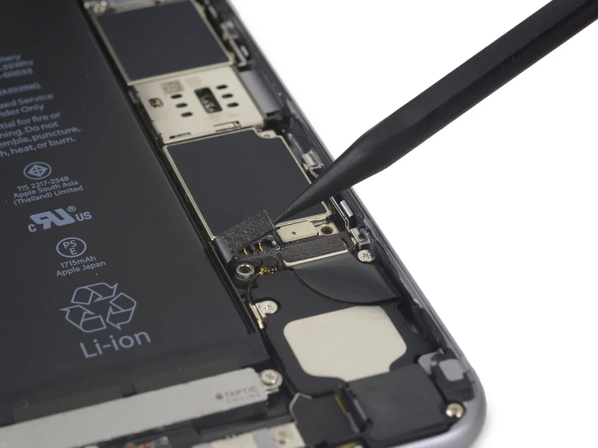
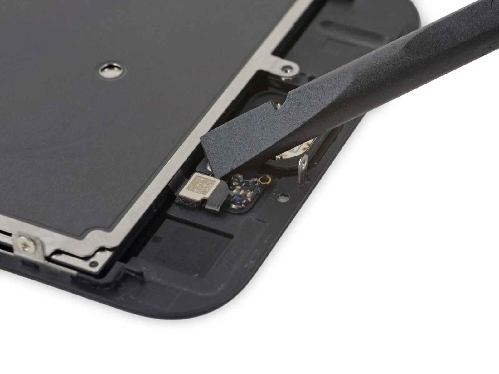
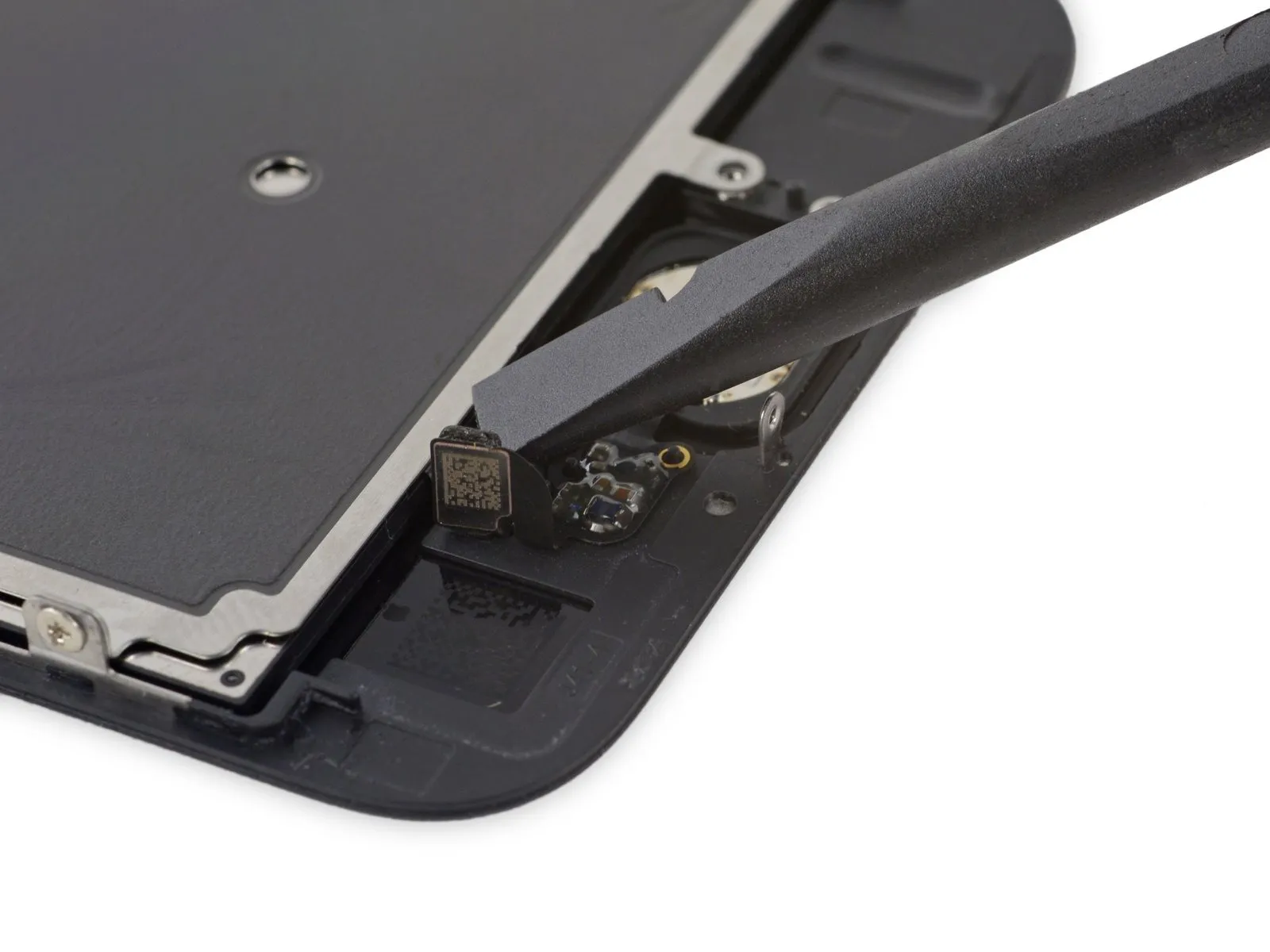
Step 29
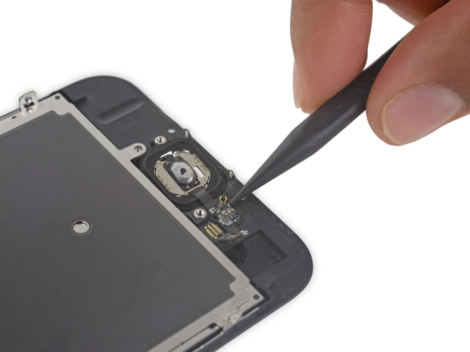

- Carefully insert the tip of the tool into the designated area.Use a plastic pry tool, often referred to as a spudger, to gently separate components.Gently detach the home button flex cable from the rear surface of the display panel.
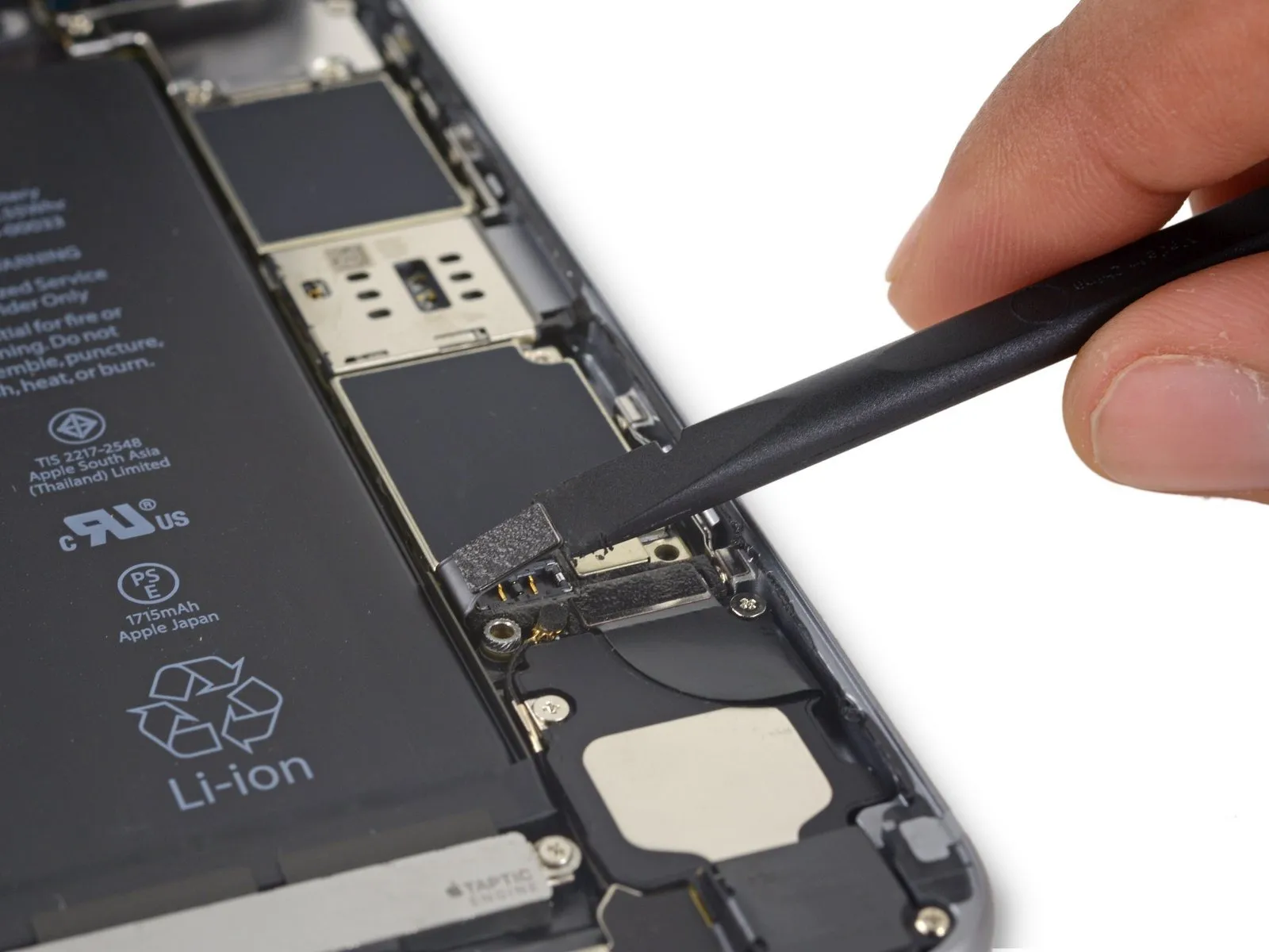
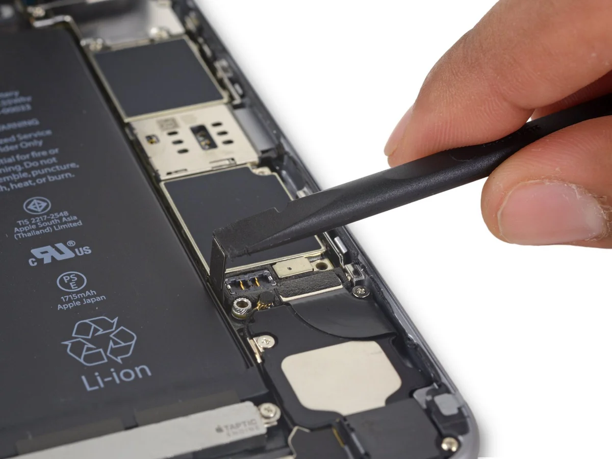
Step 30
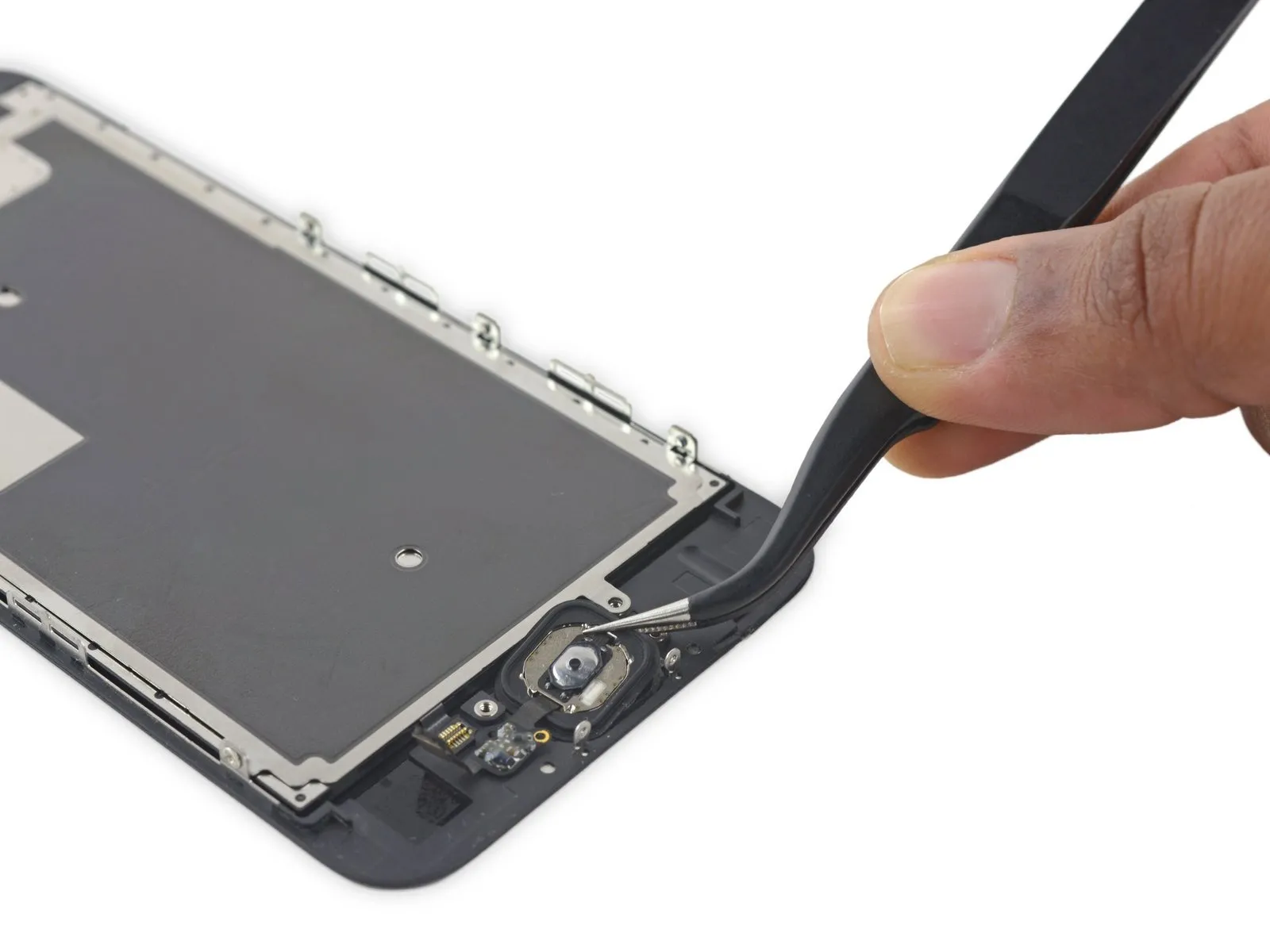
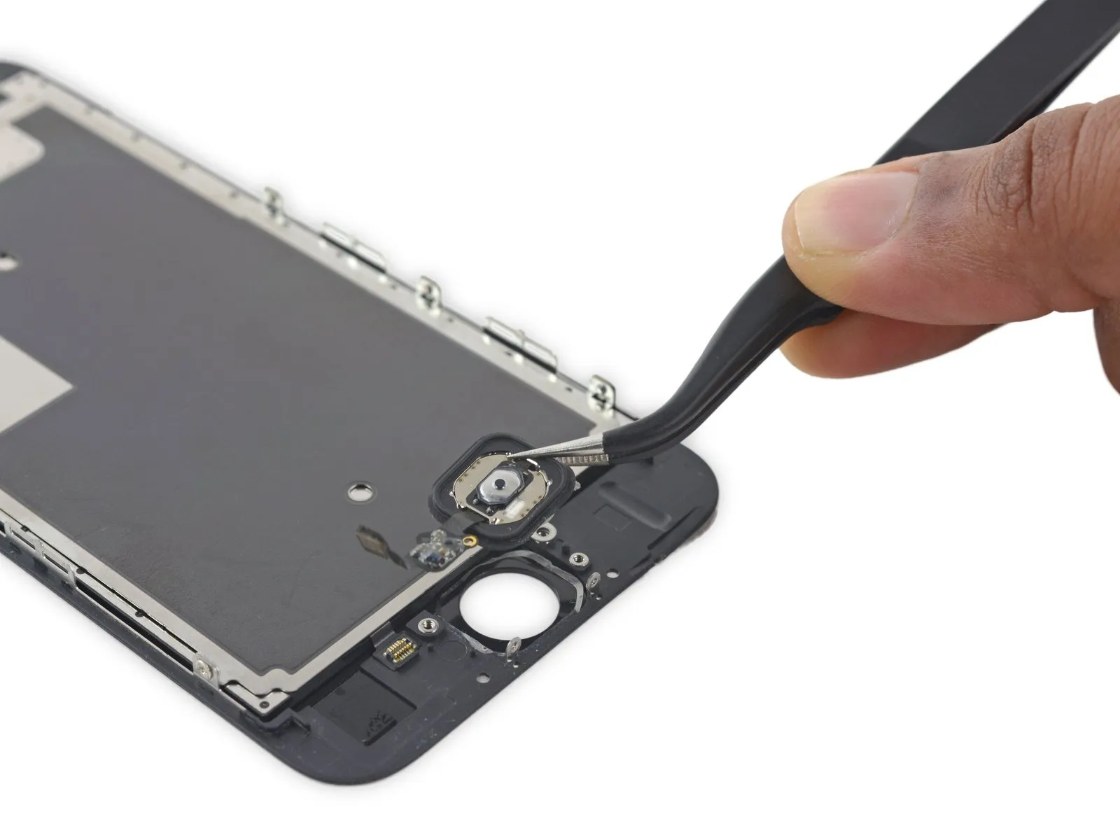
- Carefully detach the home button assembly.