iPhone 6s LCD and Digitizer Replacement
Employing our repair kit and this streamlined procedure will simplify the complete iPhone screen replacement process.
- Experienced users can proceed with the following steps.To perform this repair, this guide focuses solely on replacing the iPhone’s LCD and digitizer assembly, commonly referred to as the front panel. Prior to installation, several components must be carefully moved from your existing screen to the replacement—specifically, the front-facing camera, earpiece speaker, LCD shield plate, and the home button assembly.
- When replacing or servicing any screen or display, adhere strictly to the outlined procedures.To ensure Touch ID functionality, carefully move the existing home button to the replacement display assembly.
This document also provides instructions for substituting these components.
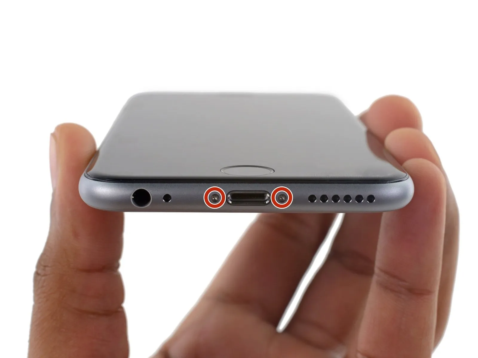
Step 1 | Pentalobe Screws
- To prevent potential hazards and damage, ensure the battery's charge level is reduced to less than 25% prior to beginning the disassembly process.A lithium-ion battery must be fully charged.Accidental puncture presents a fire and/or explosion hazard.
- To prevent electrical shock or damage, ensure the iPhone is completely de-energized prior to starting the repair process.
- Using a Pentalobe screwdriver with a 3.4 mm bit, detach the two screws located on the lower edge of the device, positioned on both sides of the Lightning connector.
Step 2 | Tape over the display


- To mitigate the risk of additional shattering and potential injury while repairing a cracked display, secure the glass with tape.
- Apply multiple layers of transparent packing tape across the iPhone screen, ensuring complete coverage to secure any fragmented glass and maintain stability during the display separation process.
- To safeguard your vision, always use safety glasses while performing this repair, as fragments of glass may become dislodged.
- Should the damaged glass prevent a secure suction cup attachment during subsequent procedures, utilize a folded section of durable tape—like duct tape—to create a lifting handle for the display.
Step 3 | Anti-Clamp instructions


To simplify the opening process, the following two steps utilize the Anti-Clamp tool, a custom-designed aid; if you do not have this tool, proceed to the instructions three steps further down.
Refer to the included guide for detailed procedures regarding Anti-Clamp operation.
- To release the Anti-Clamp's arms, move the blue handle in a rearward direction.
- Position the arms so they extend past either the left or right side of the iPhone.
- Affix one suction cup to the front surface of the iPhone, close to the lower edge and directly over the home button, and secure a second suction cup to the rear surface in the same relative position.
- Apply vacuum to the targeted region by pressing the cups firmly against each other.
- To enhance the Anti-Clamp's grip if the iPhone's exterior feels excessively smooth, apply adhesive tape to the device's surface.
Step 4


- To secure the arms, advance the blue handle in the direction indicated.
- Rotate the handle a full 360 degrees, observing the cups as they expand; maintain their parallel alignment. Should the cups become misaligned, gently release the suction and reposition the arms to restore proper alignment.
- Once sufficient space is created by the Anti-Clamp, slide a prying tool beneath the display panel.
- To ensure adequate separation, incrementally adjust the handle by 90 degrees, pausing for several seconds after each adjustment; avoid exceeding a 90-degree rotation per increment, allowing the Anti-Clamp to function effectively.
Step 5 | Opening Procedure
- Ensure availability of a 3/8-inch socket wrench for this step.Employ a clamping prevention measure.To operate the suction handle, proceed with the subsequent three actions.
- Using a heat gun or hairdryer set to a low temperature, gently warm the bottom edge of the iPhone's casing.Use a specialized device called an iOpener.Apply heat with a hairdryer, maintaining its proximity, for approximately 60 seconds.
- Applying heat will loosen the adhesive that holds the display in place, facilitating separation.
Step 6
Removing the 6s display involves releasing a perimeter adhesive strip. Replacement adhesive strips are recommended for this process; however, the repair can be performed without them, and operational performance should remain unaffected.
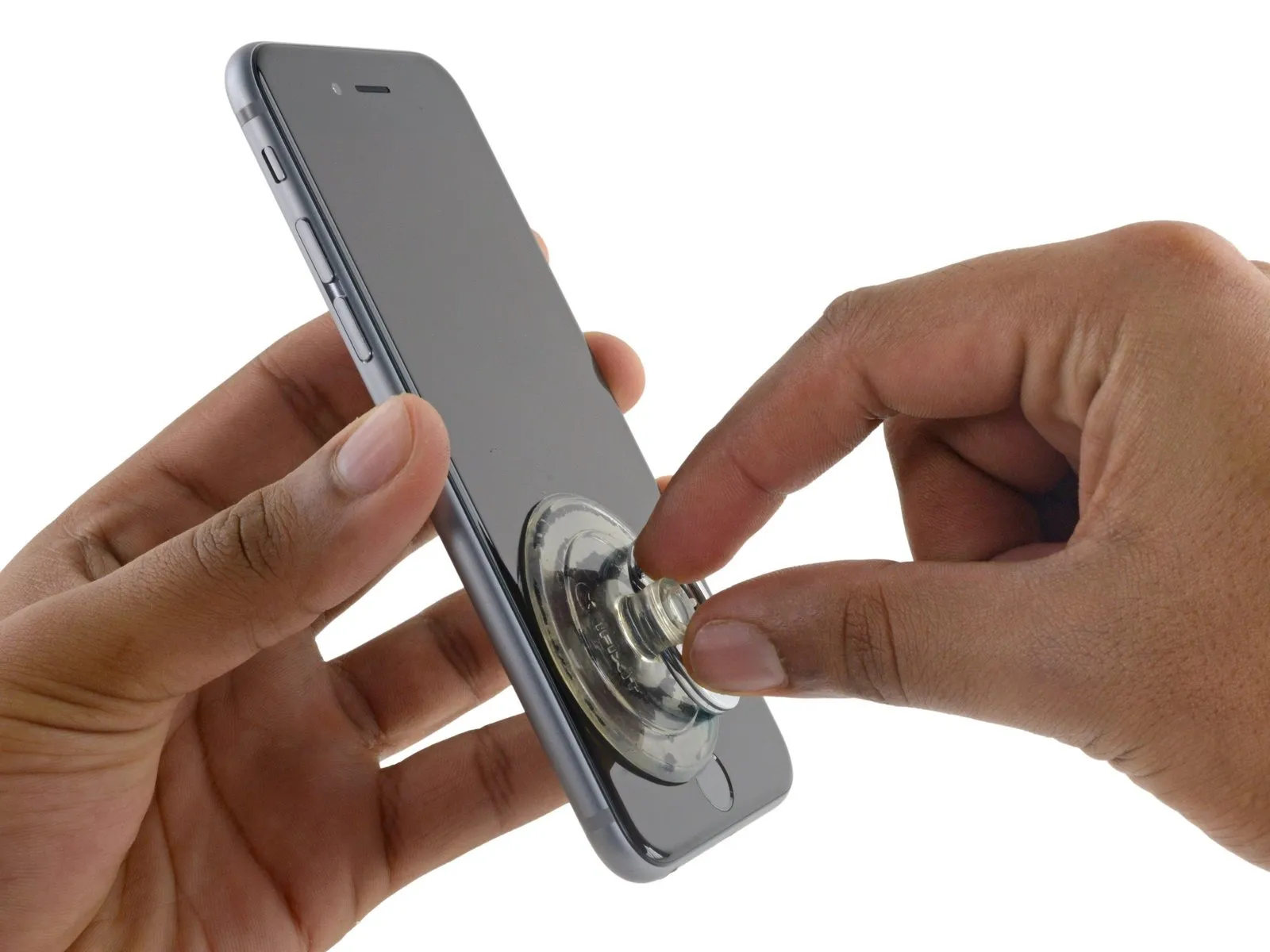
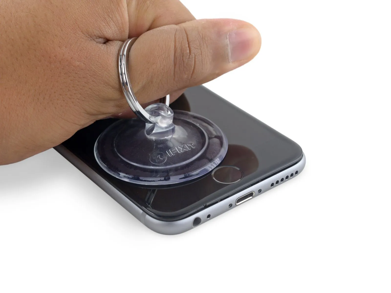
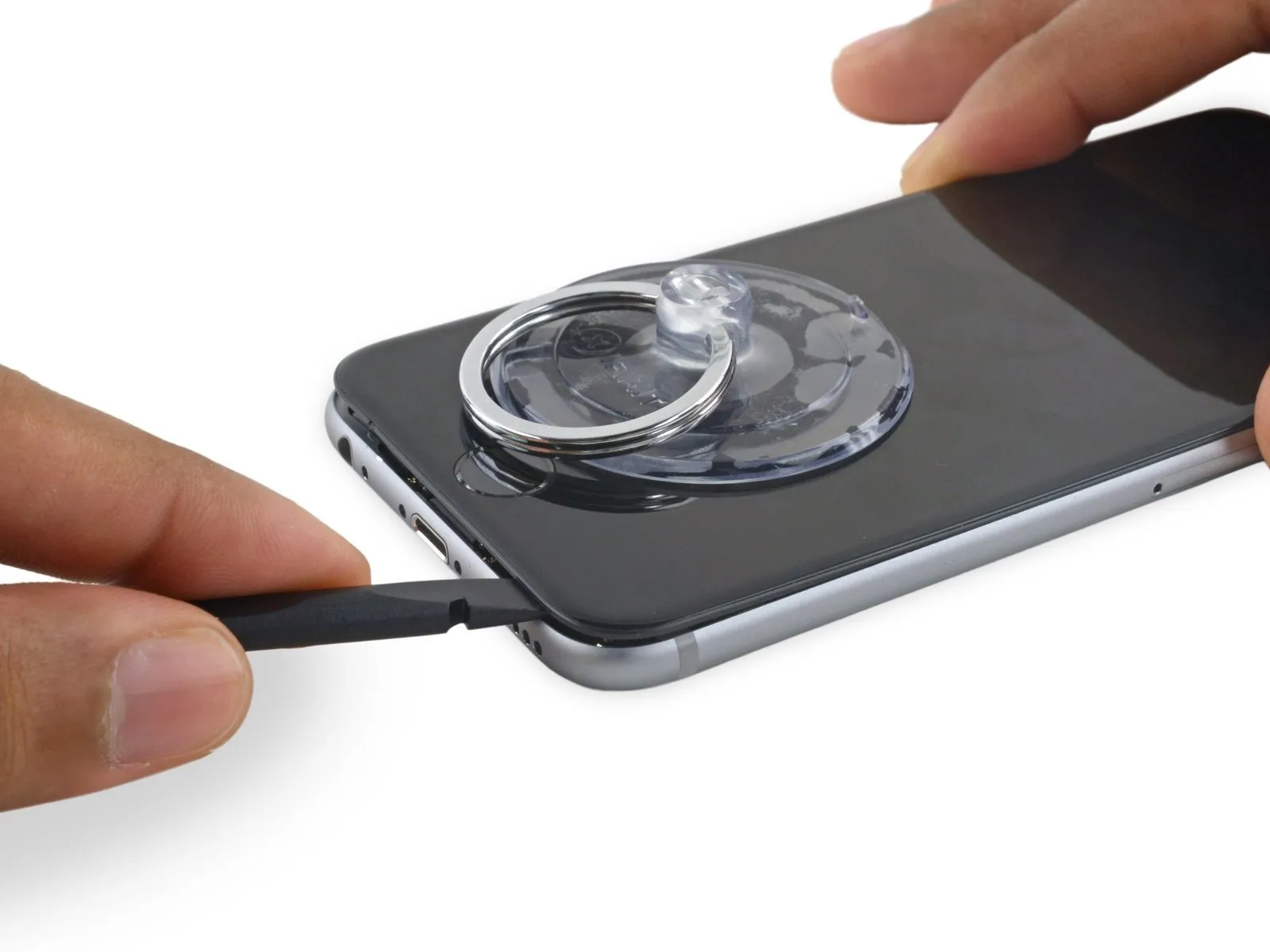
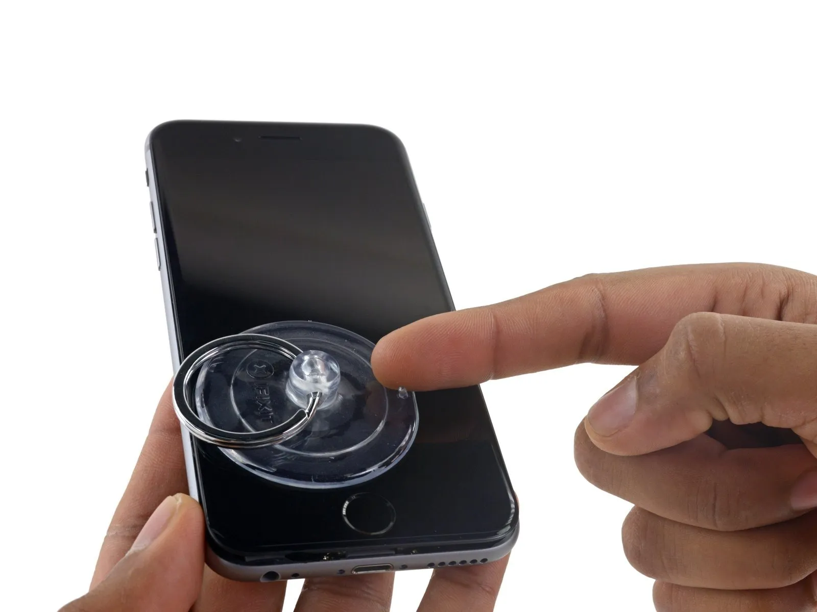
- Securely attach a suction cup to the display assembly's lower left corner.
- Avoid positioning the suction cup directly atop the sensor.Press the front panel's central control to activate the device's main menu..
- To facilitate suction cup attachment when the display has severe cracking, apply a sheet of clear packing tape across the damaged area; as an alternative, a robust adhesive tape can be used in place of the suction cup. As a last resort, secure the suction cup directly to the fractured screen with superglue.
Step 7
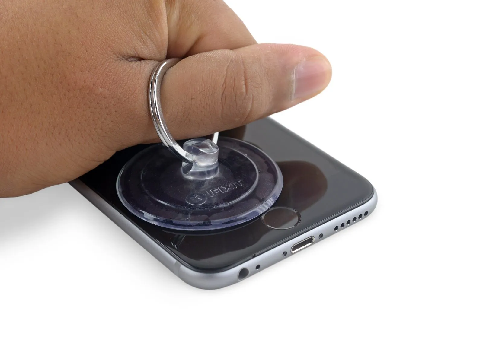
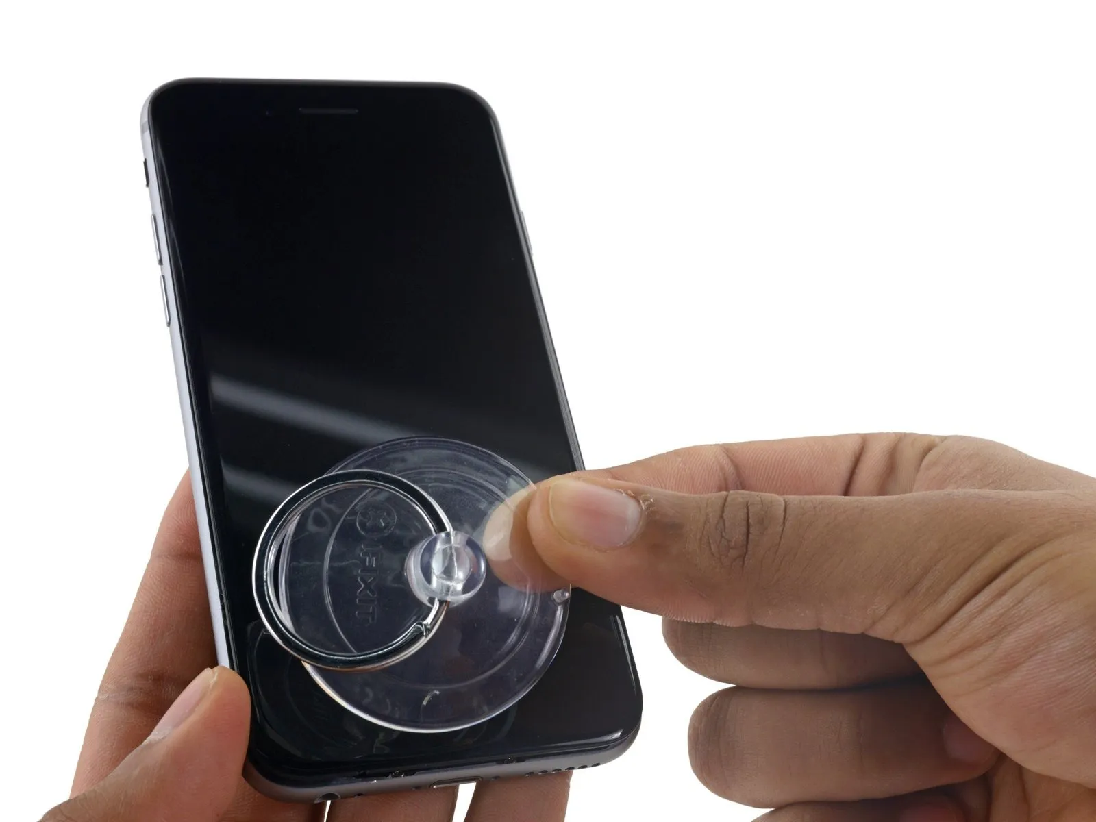
Apply steady, even force to lift the suction cup, generating a small separation between the front panel and the rear case.
Exercise caution and use steady, even pressure during installation; the display unit's fit is considerably snugger than typical device components and secured with adhesive.
To avoid display assembly damage, use only the necessary force to separate the display assembly from the rear case, creating a slight space.
To resolve potential issues, apply warmth to the device's front surface with a heat source.Use the iOpener.Apply heat from a hair dryer or heat gun to the display's edges until the surface reaches a temperature just beyond comfortable touch, which facilitates loosening of the adhesive bond.
Step 8
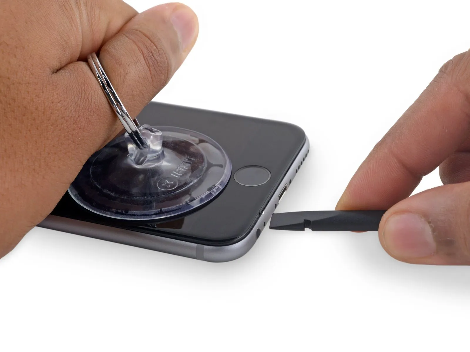
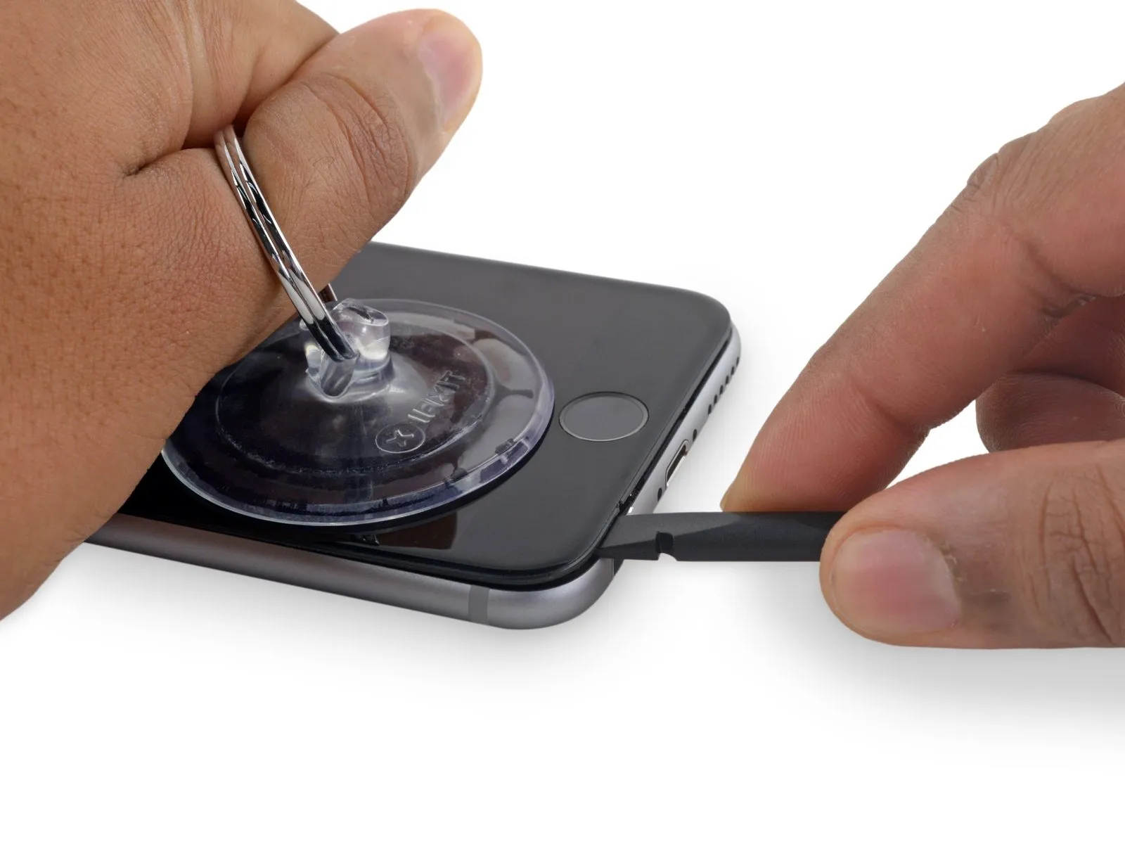
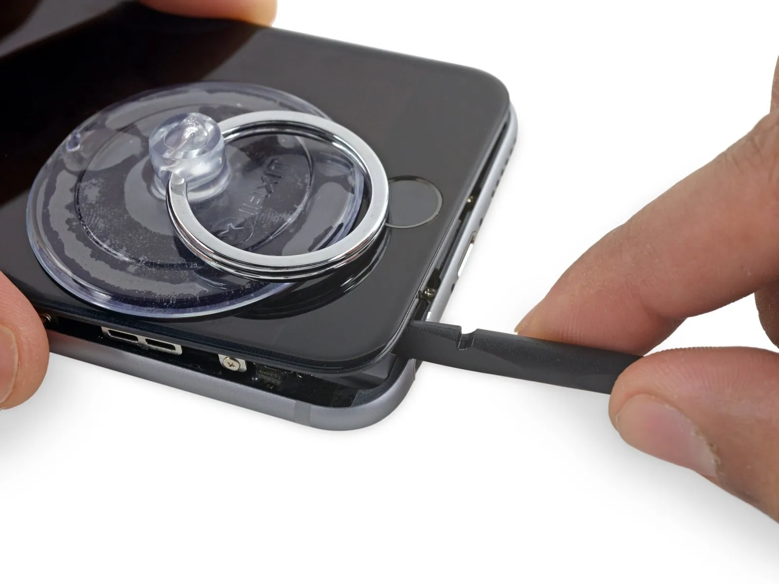
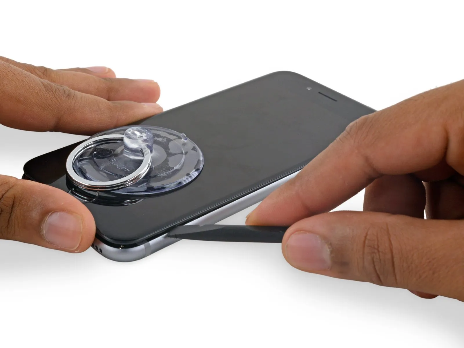
Carefully start separating the phone's casing by inserting a prying tool into the indentation located on the bottom of the display, directly above the headphone jack.
Using a spudger, insert the flat end into the separation between the display and the back cover, positioning it immediately over the headphone jack.
Step 9
Step 10
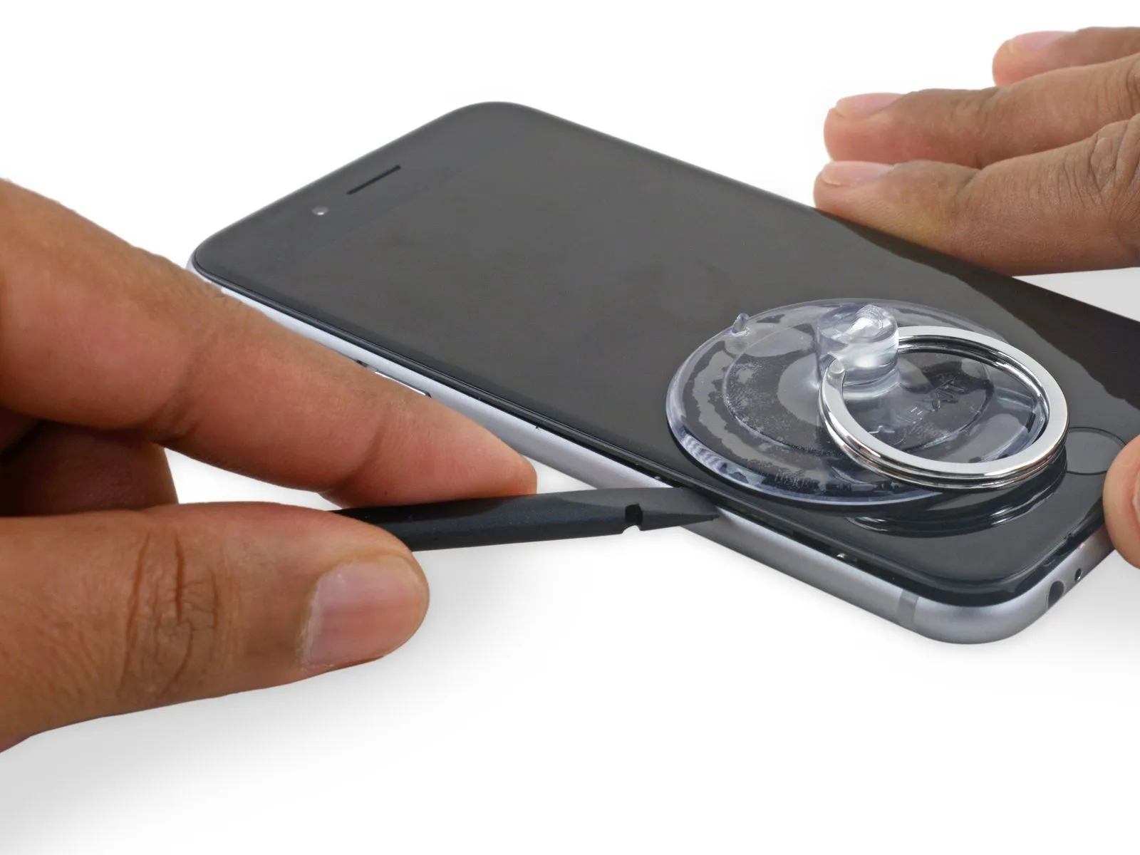
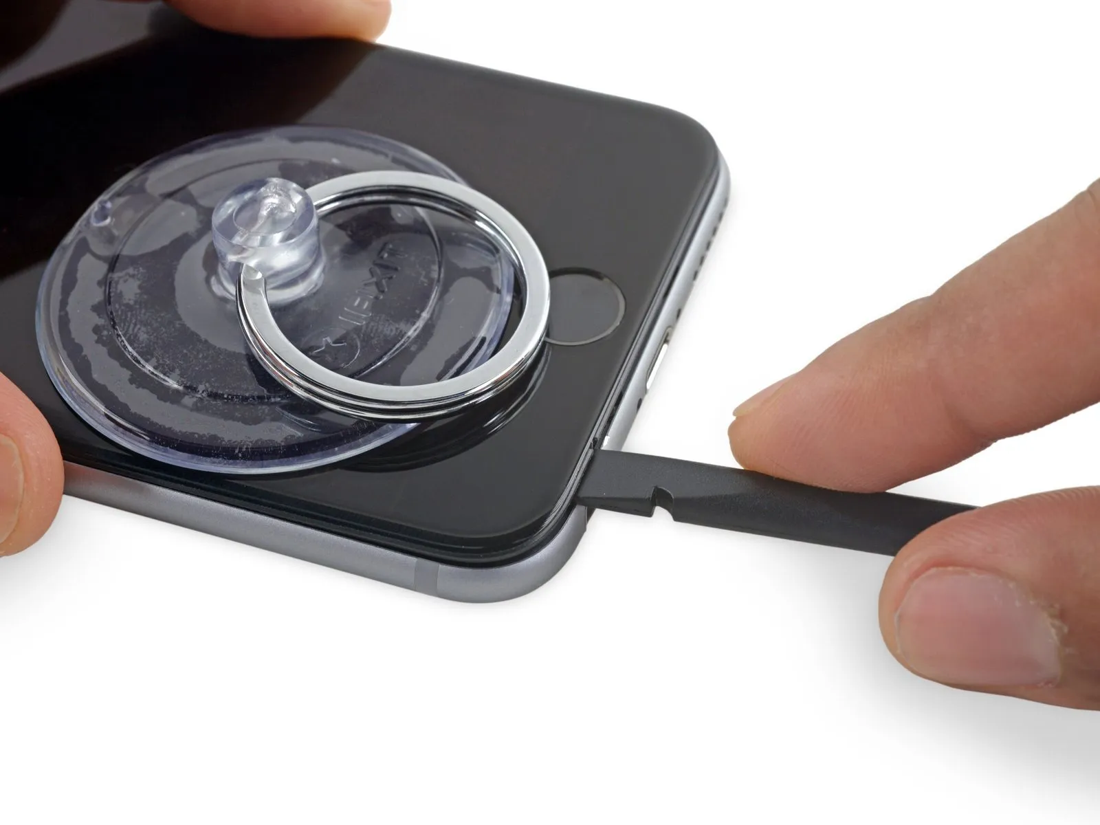
- Using the tool's straight tip, carefully slide it into the designated space.Use a plastic pry tool, often referred to as a spudger.Locate the area on the device's left lateral surface, positioned in the space separating the display assembly and the rear case.
- Carefully move theUse a plastic pry tool to gently separate.Carefully lift the phone's side to release the adhesive bond and disengage the retaining clips.
Step 11
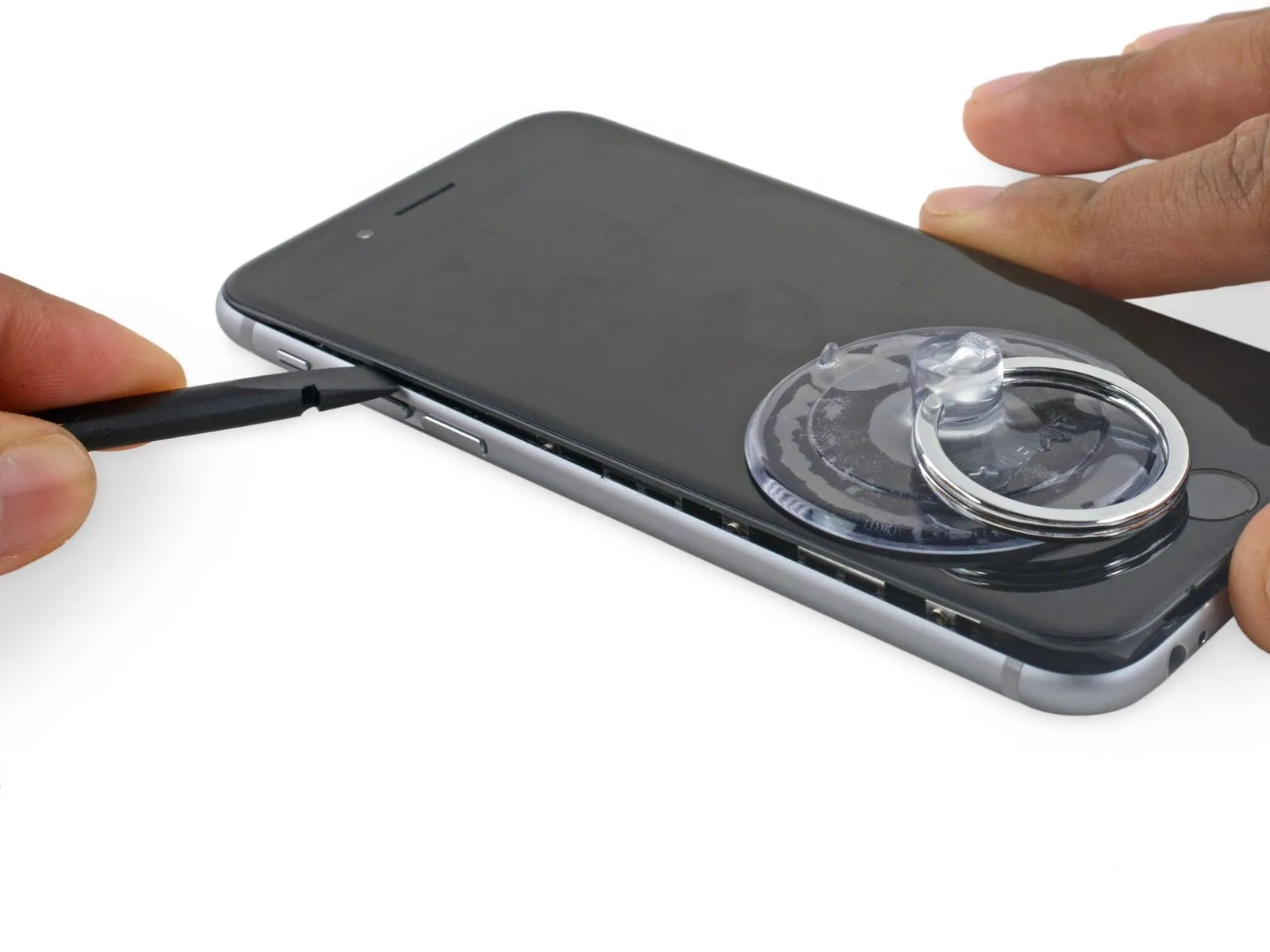
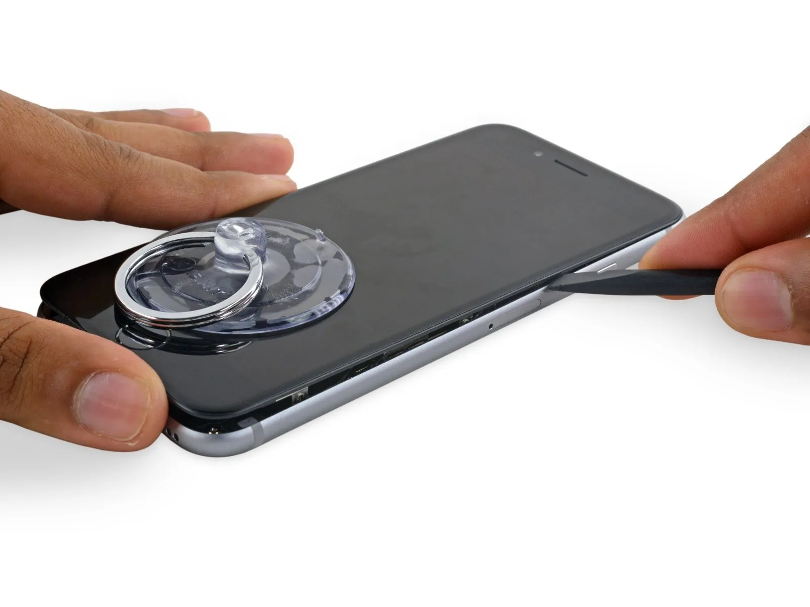
- Carefully detach theUse a plastic pry tool to access.Carefully align the component with the lower edge of the device, precisely where the separation was initially created.
- Carefully move theUse a spudger.Locate the edge of the device's lower perimeter on its right-hand side.
Step 12
Step 13
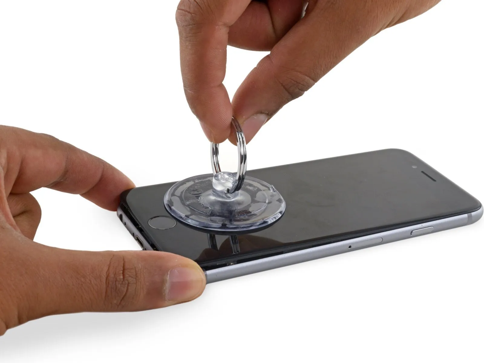

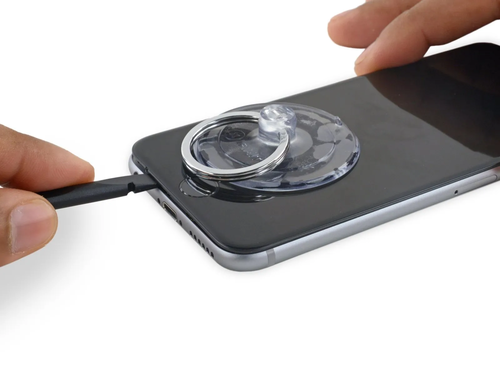
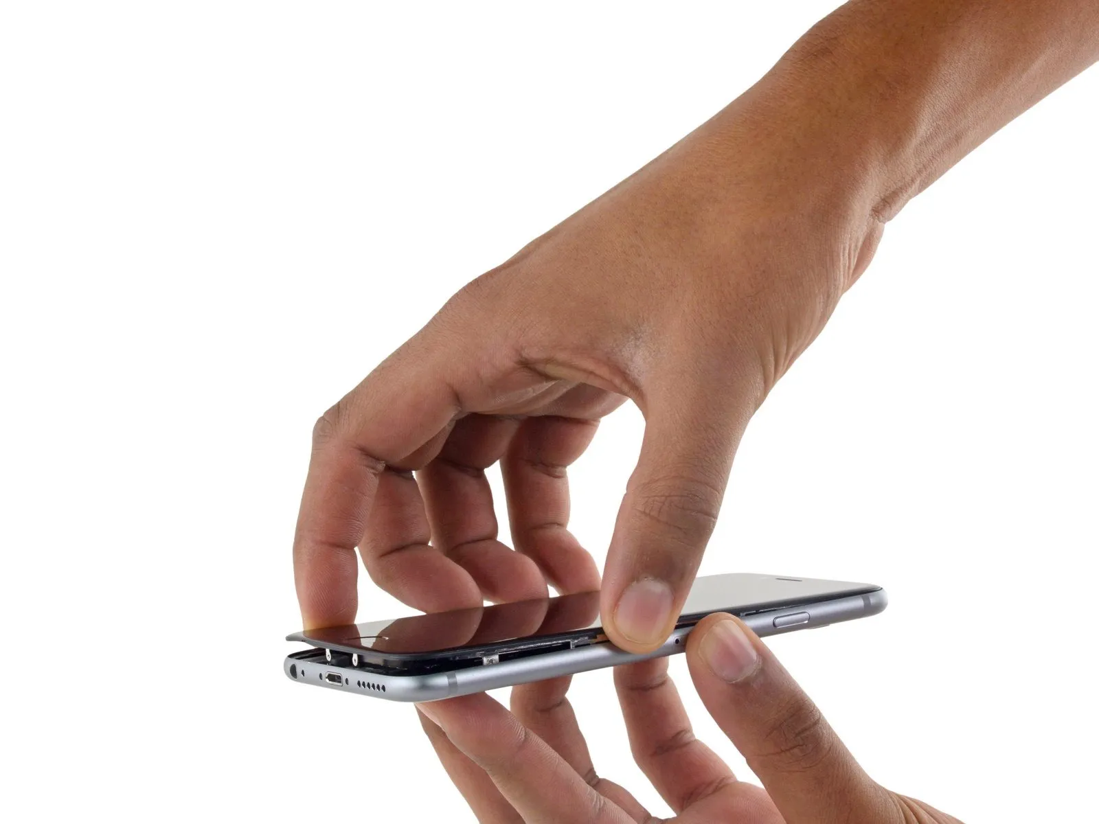
- Employ the suction cup to release the display, ensuring complete separation from the remaining adhesive.
- To prevent damage, limit the display's opening angle to a maximum of 90 degrees; the three cables connecting it to the top edge are susceptible to breakage if pulled taut.
Step 14
To detach the suction cup, grasp the small projection located on its upper surface and lift, separating it from the front panel.
Step 15
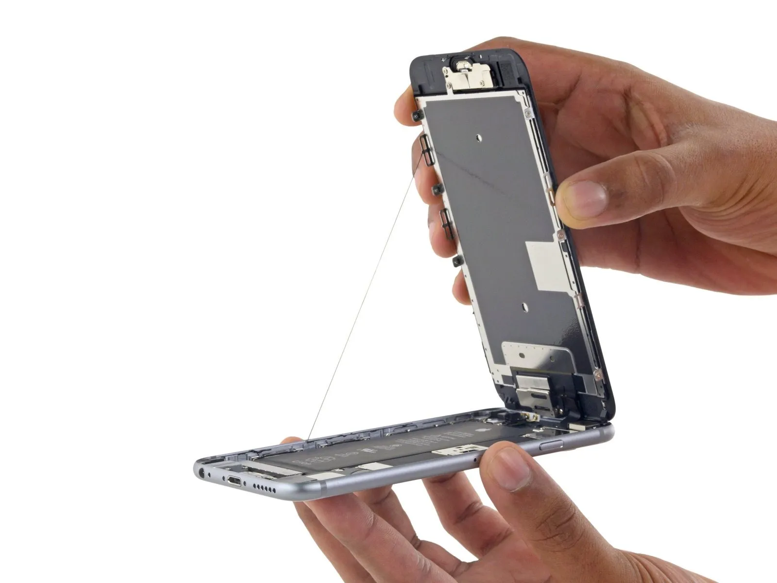
- Employing a careful grip, raise the display assembly to separate the phone, leveraging the front panel's top clips as a pivot point.
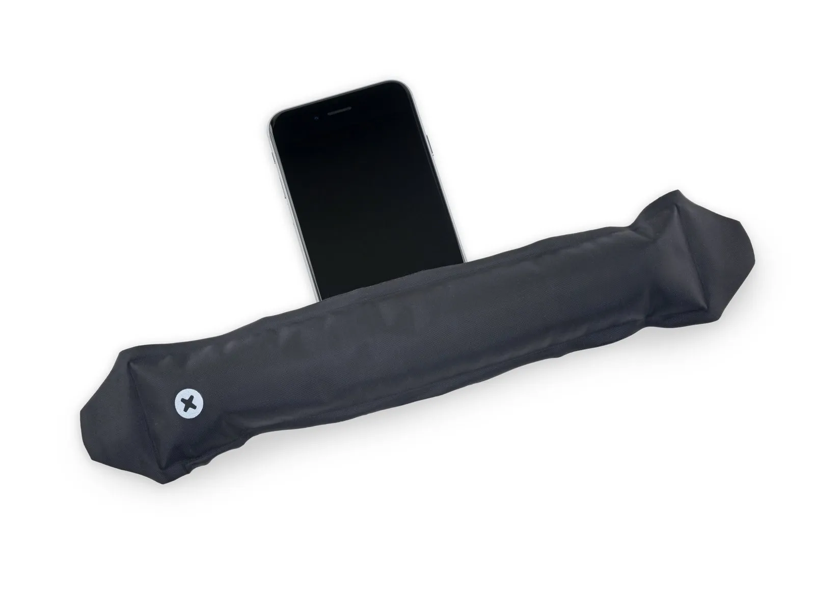
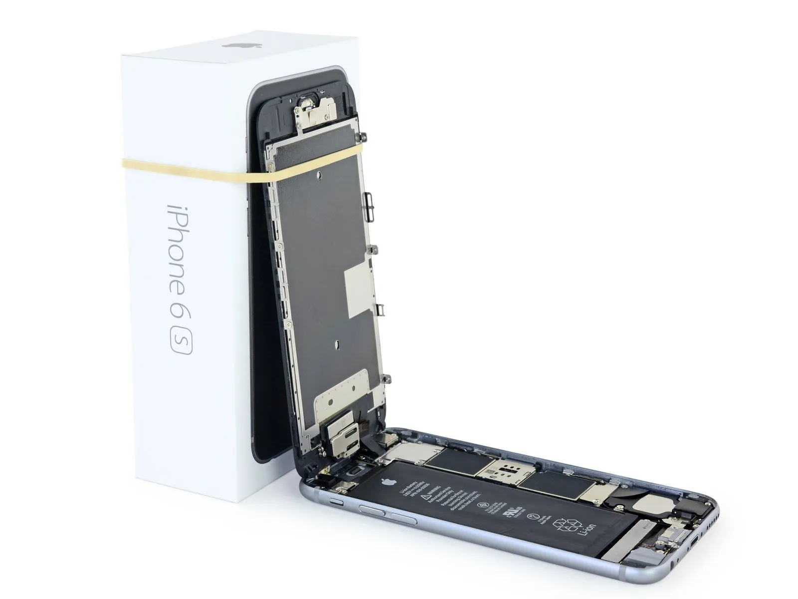
- Carefully position the display at a roughly 90-degree angle, then secure it in place using a support to prevent it from moving during the repair process.
- To avoid stressing the display's wiring during the repair process, secure it with a rubber band.
- As a temporary measure, an unopened, factory-sealed can of soda can substitute for the display during the repair process.
- If you intend to substitute new adhesive for the existing sealant along the display's perimeter during reassembly, stop at this point.
- To ensure proper alignment during reassembly, position the camera-side edge of the screen body beneath the main body's edge. The screen frame's hooks should be situated under the main body's rim, then gently pushed towards the camera end to facilitate cover closure and secure clipping.
- Position these clasps beneath the phone's outer edge, as they function as a closure mechanism rather than a traditional hinge; this ensures the screen returns smoothly and securely, gently clicking into its closed position.
- To reinstall the screen, begin by applying pressure to secure the upper right corner, working downwards along the edge, followed by the upper left corner.
Step 16 | Battery Connector
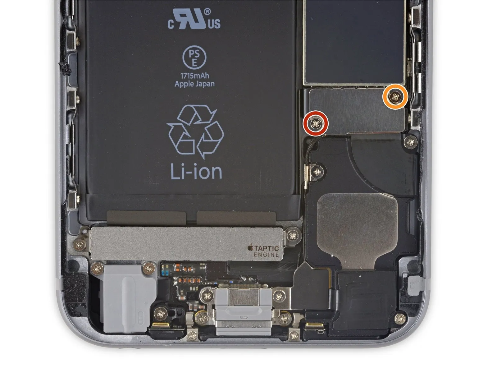
Using a Phillips screwdriver, detach the two screws—each measuring the same length—that hold the battery connector bracket in place.
A single screw, measuring 2.9 millimeters, is required.
A screw with a 2.2 mm head diameter is required.
Carefully note the location of every screw during disassembly, as reassembly requires that each one be placed in its original position to prevent damage to the iPhone.
Step 17
Step 18

Step 19
Step 20 | Unfasten the display cable bracket
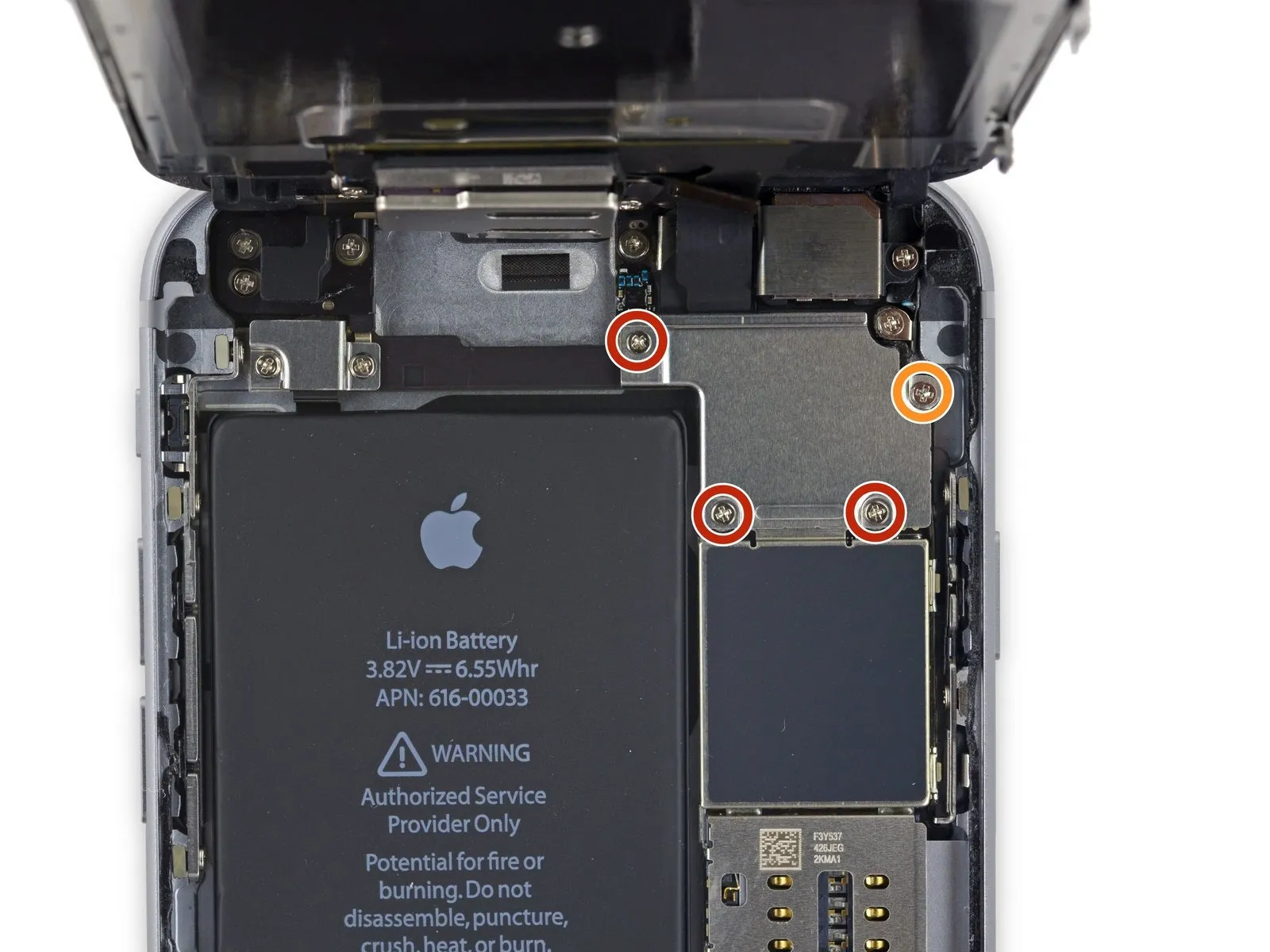
- Carefully detach the group of four.Use a Phillips head screwdriver.Affix the display cable bracket using the provided 6mm hex key, ensuring it's tightened to a torque of 4.5 Nm and observing all safety precautions regarding pinch points.
- A quantity of three is required.Use screws with a diameter of 1.2 millimeters.
- Begin the process by executing the action designated as "One."Use a 2.8-millimeter screw.
Step 21
Step 22
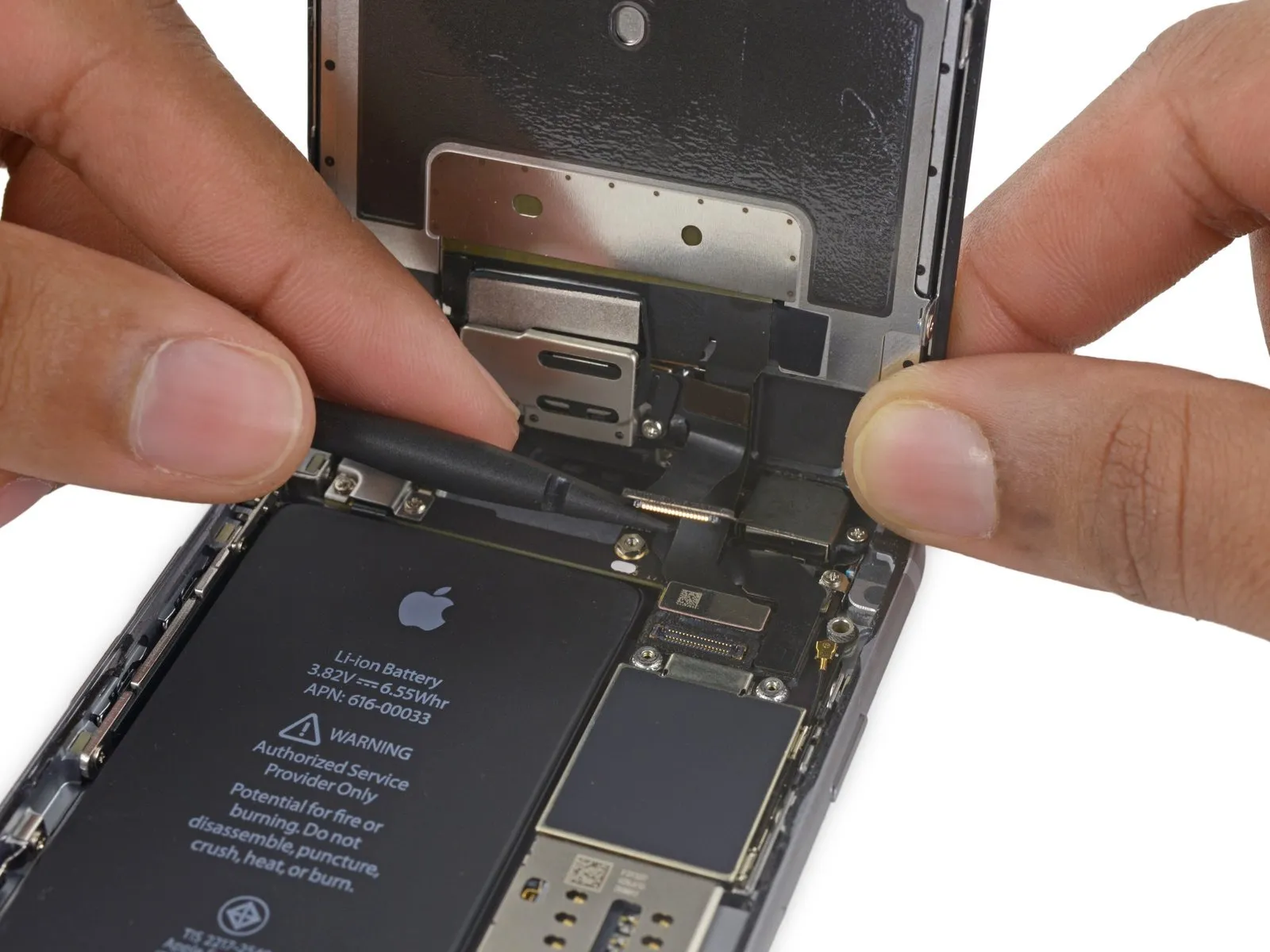
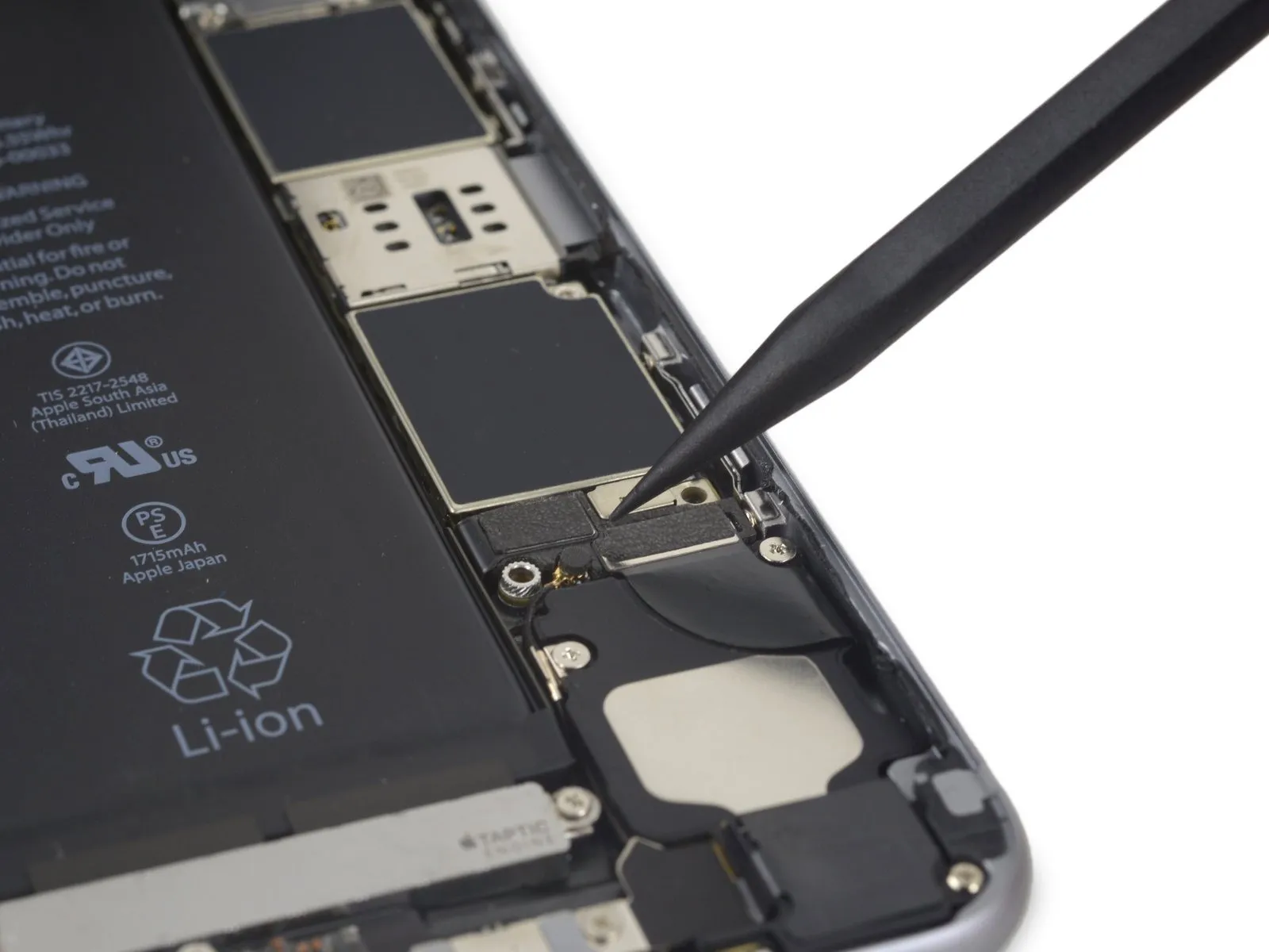
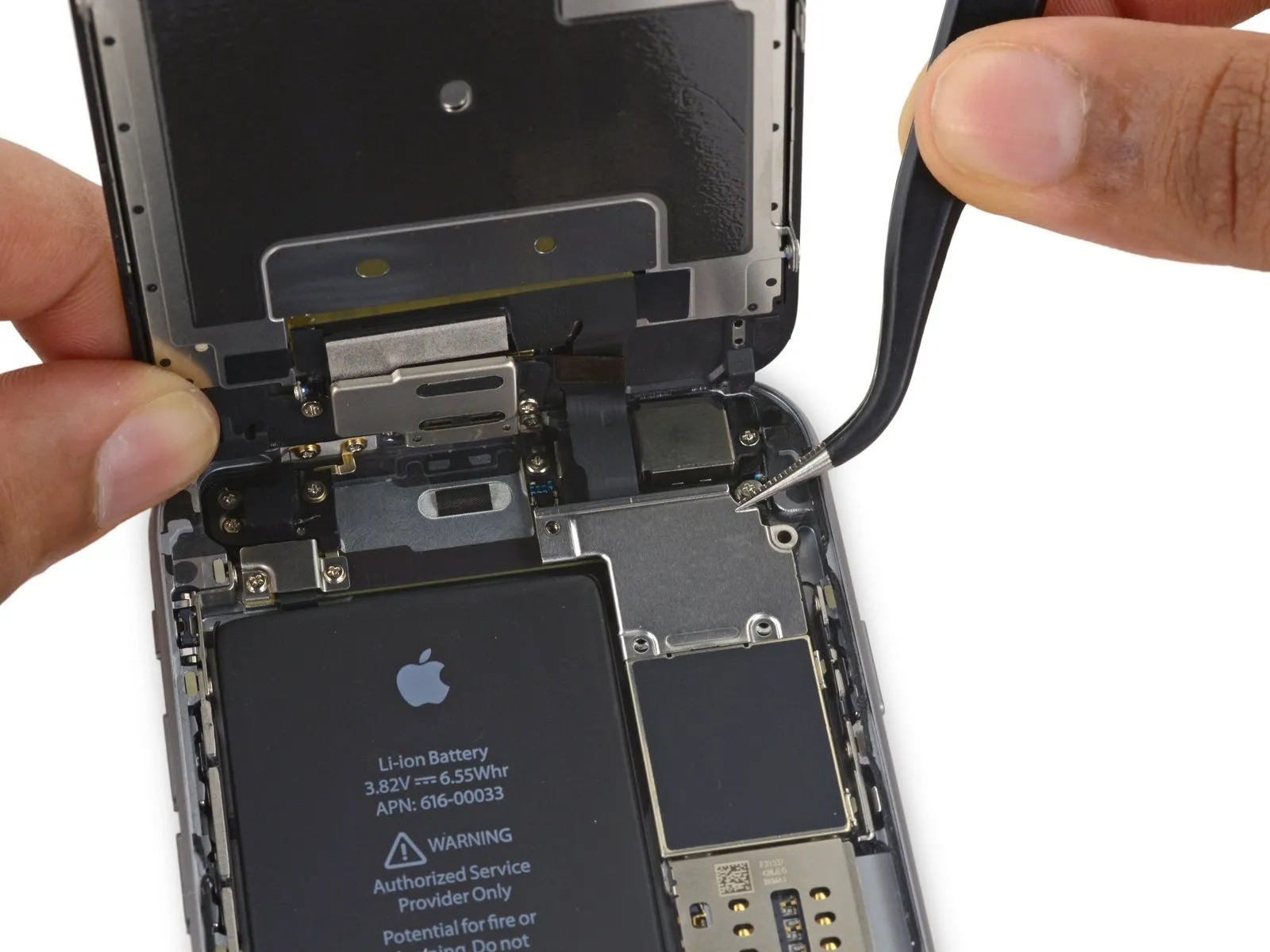
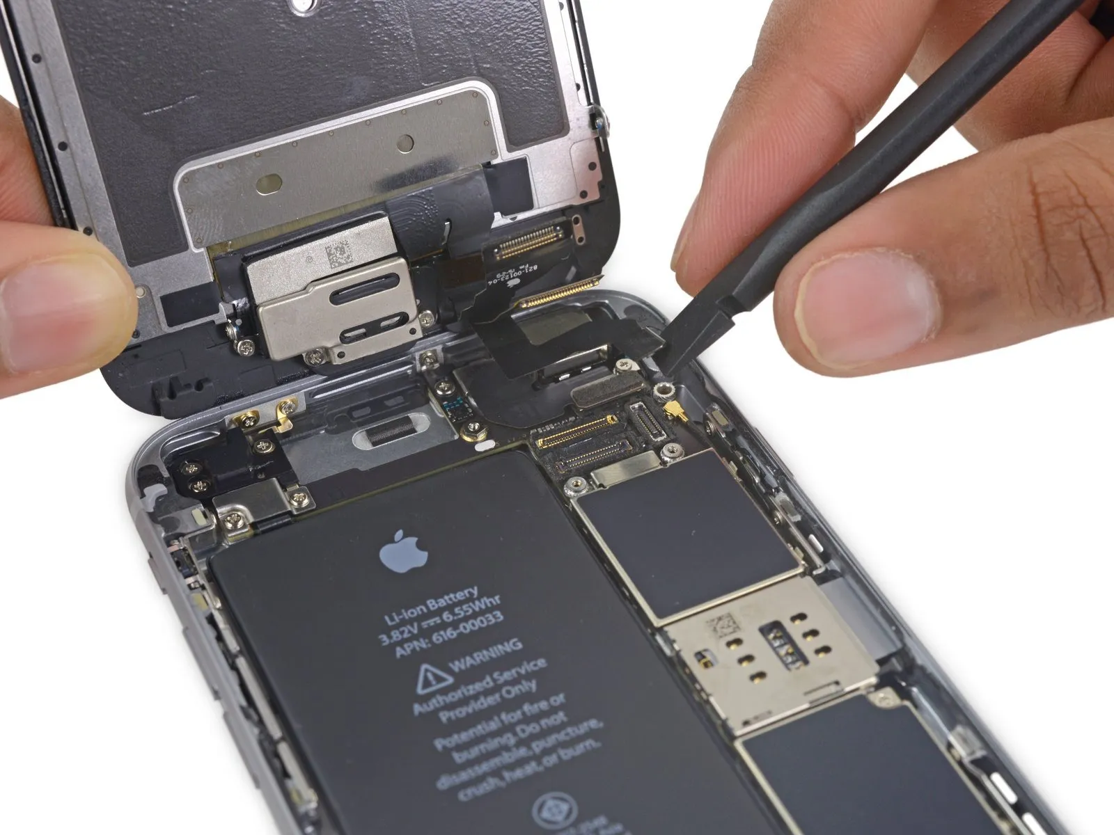
- Carefully detach the front camera flex cable from its connector on the logic board by gently levering it upwards with a spudger or a clean fingernail.
Step 23
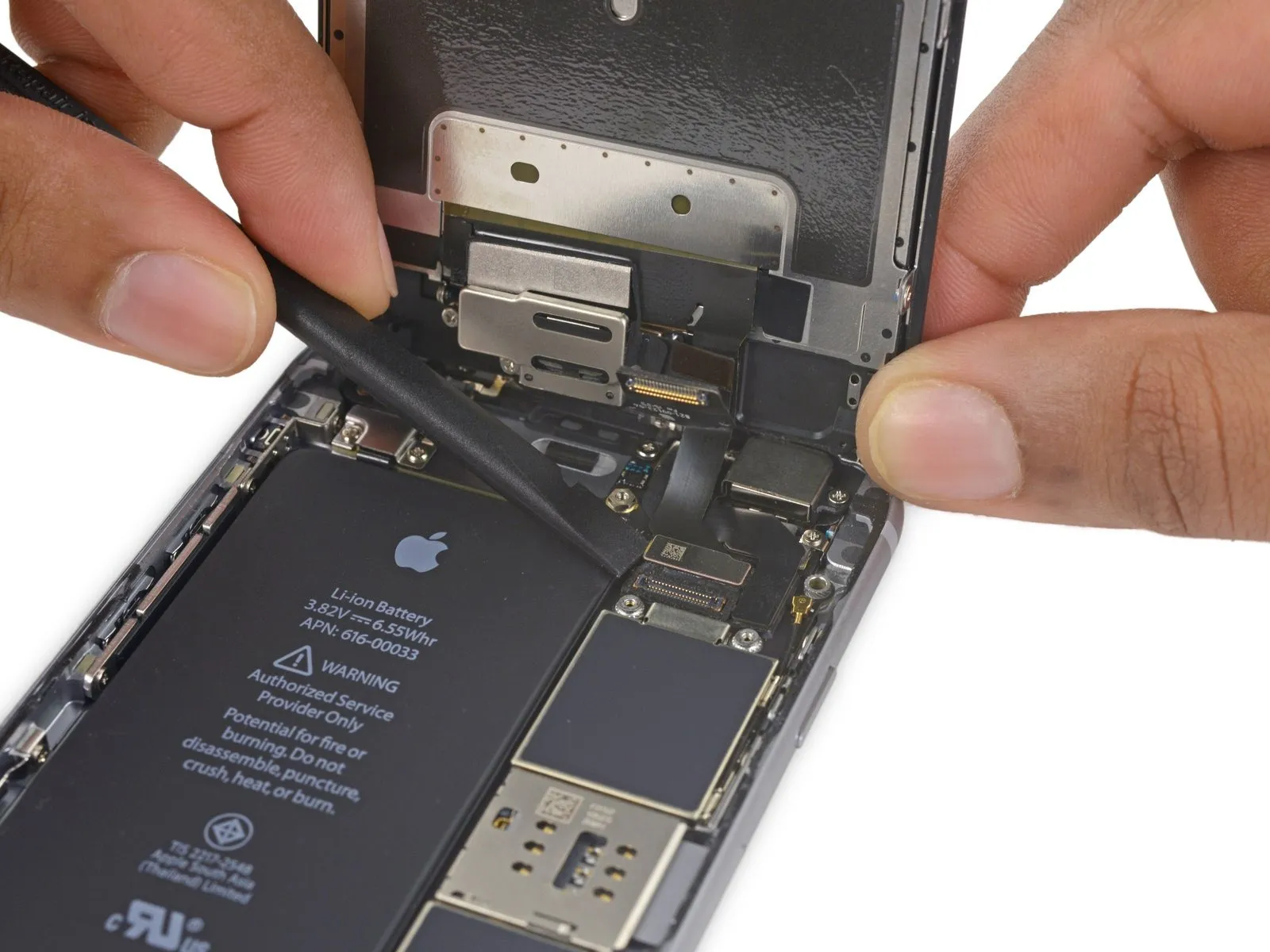
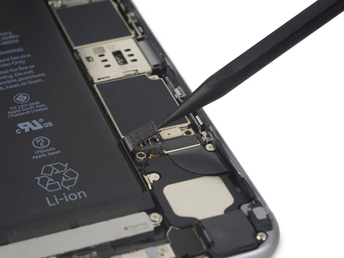
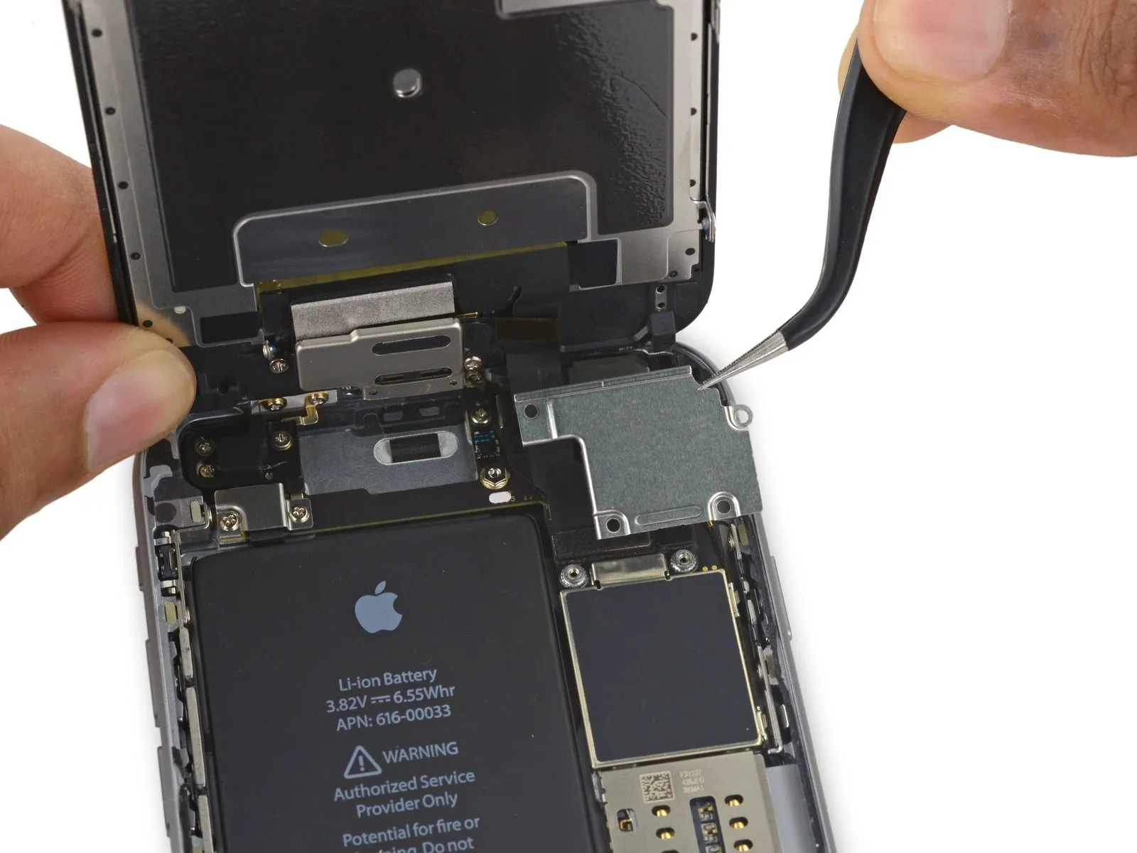
- Using a prying tool, carefully release the digitizer cable from its connection on the logic board by applying upward force.
- To ensure proper alignment and prevent damage, avoid applying pressure to the connector's middle when reattaching the digitizer cable; instead, gently secure it by pressing first one end, then the other. Central pressure risks bending the component.The display's touch functionality is impaired due to damage to the digitizer..
Step 24
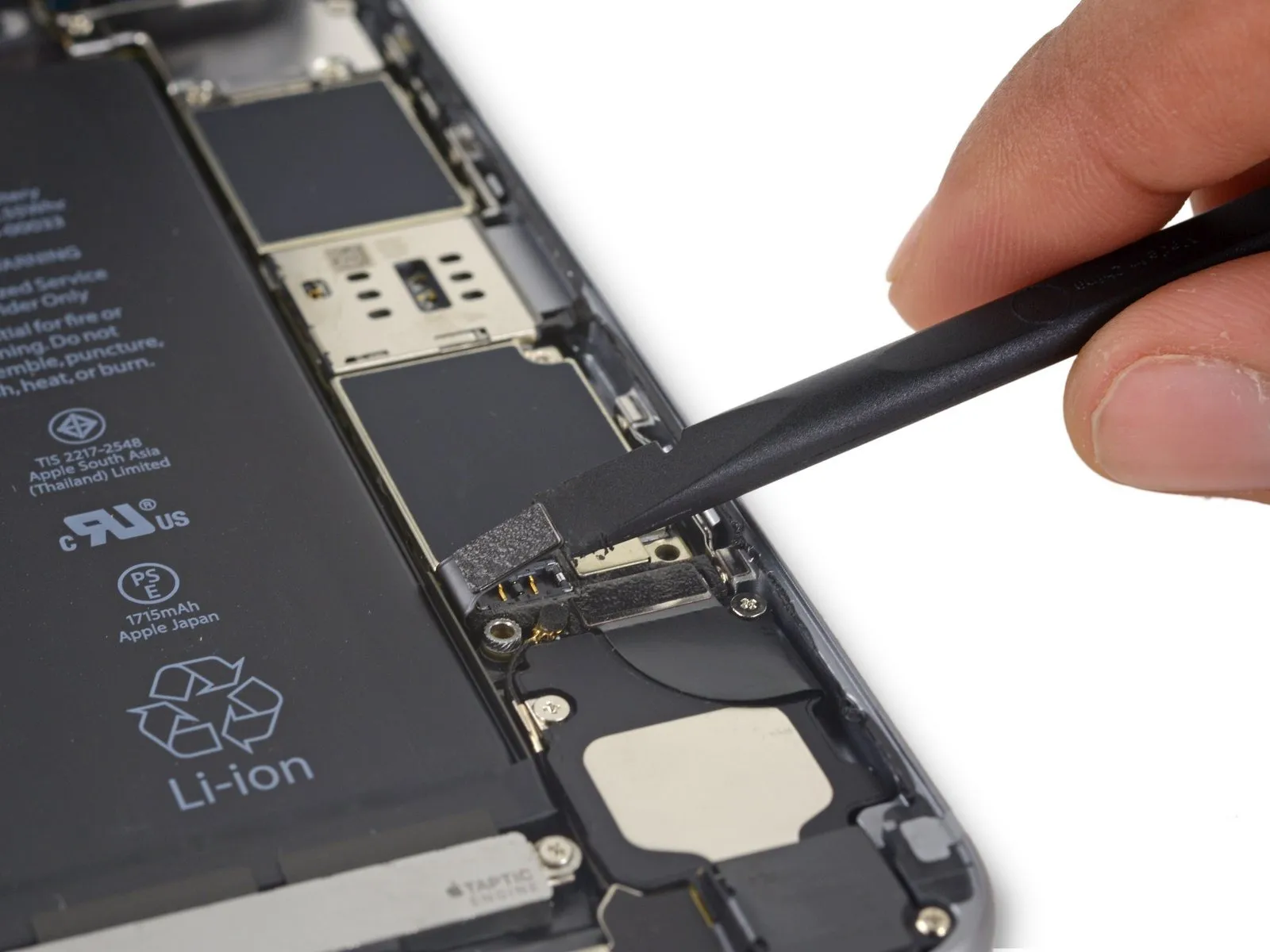
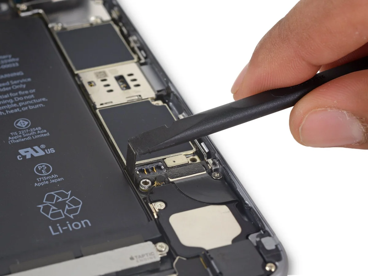
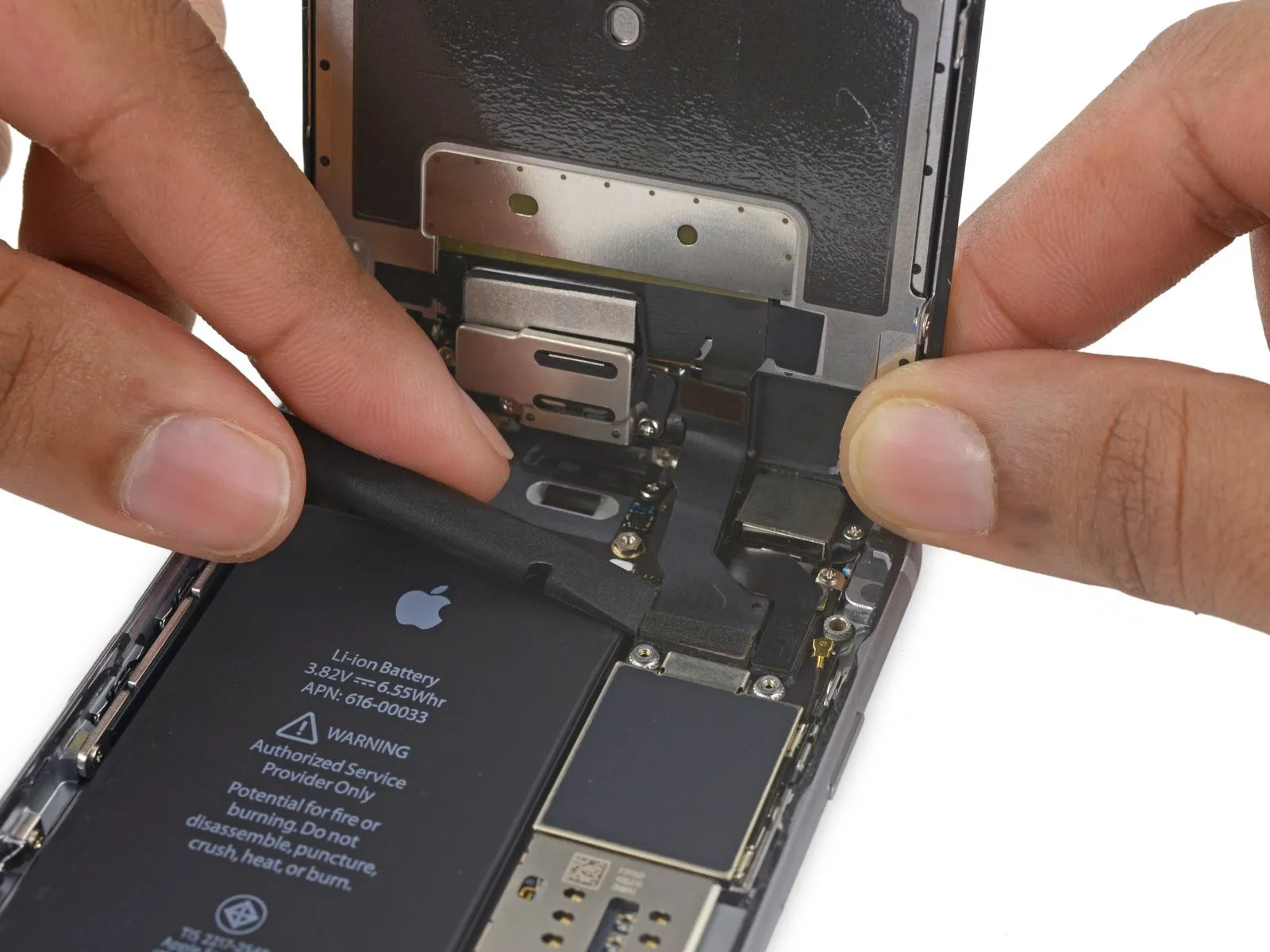
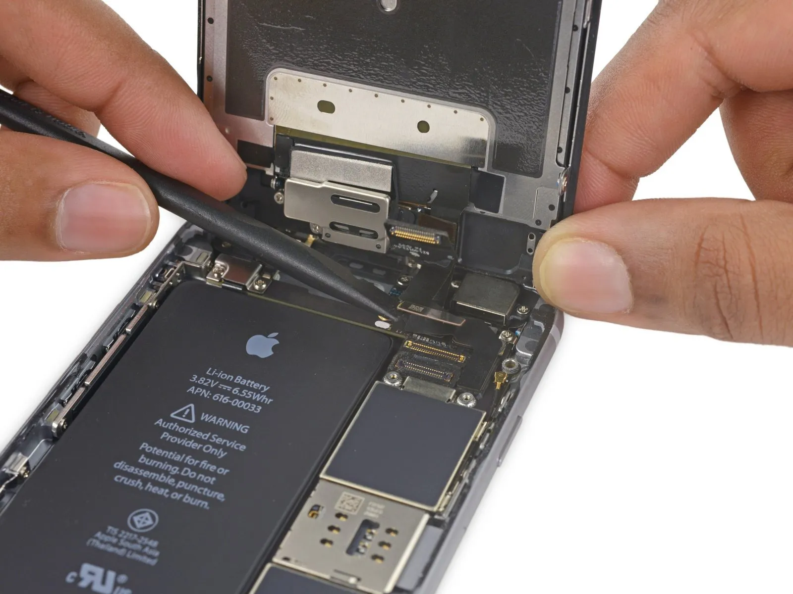
- Prior to either detaching or reattaching the cable in this procedure, ensure the battery is disconnected.
- Carefully lift the display cable vertically away from its connector on the logic board.
Step 25
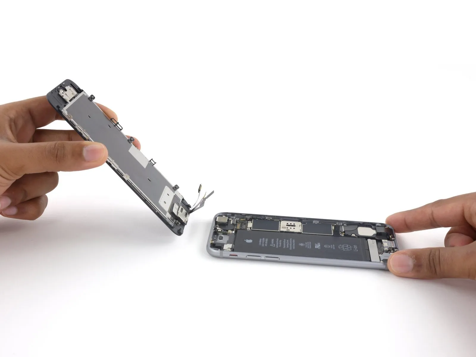
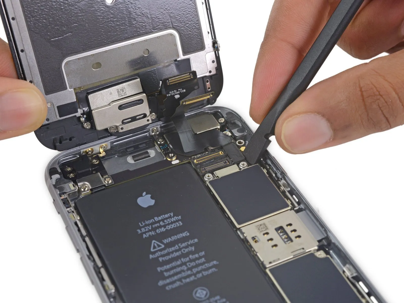
- Carefully detach the display assembly, ensuring all connections are released.
- If you intend to substitute fresh adhesive along the display's perimeter during reassembly, stop at this point.
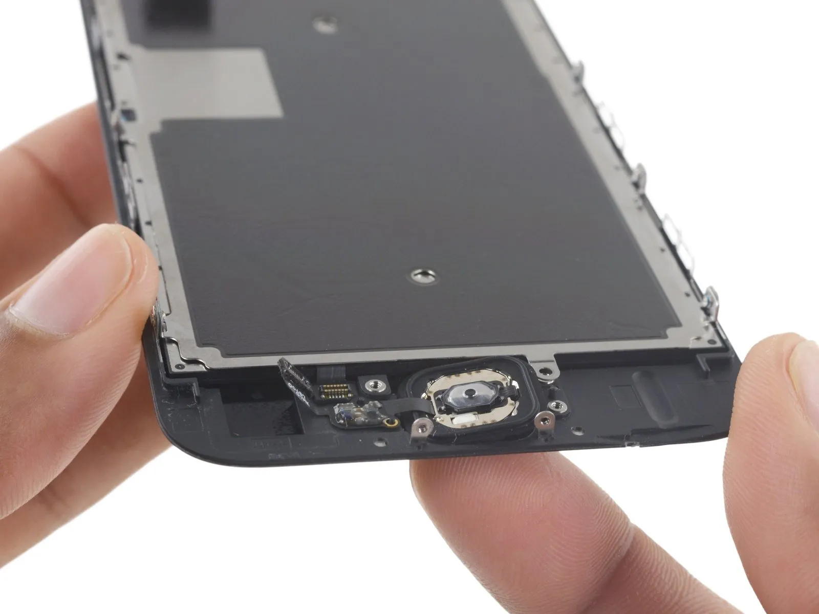
Step 26 | Home Button Assembly
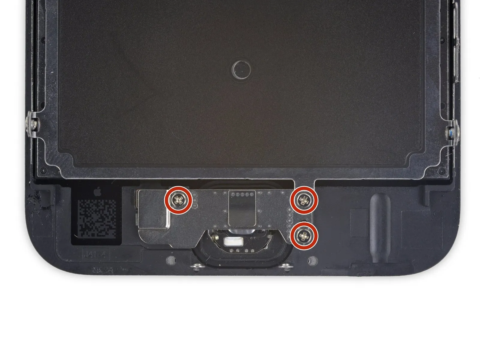
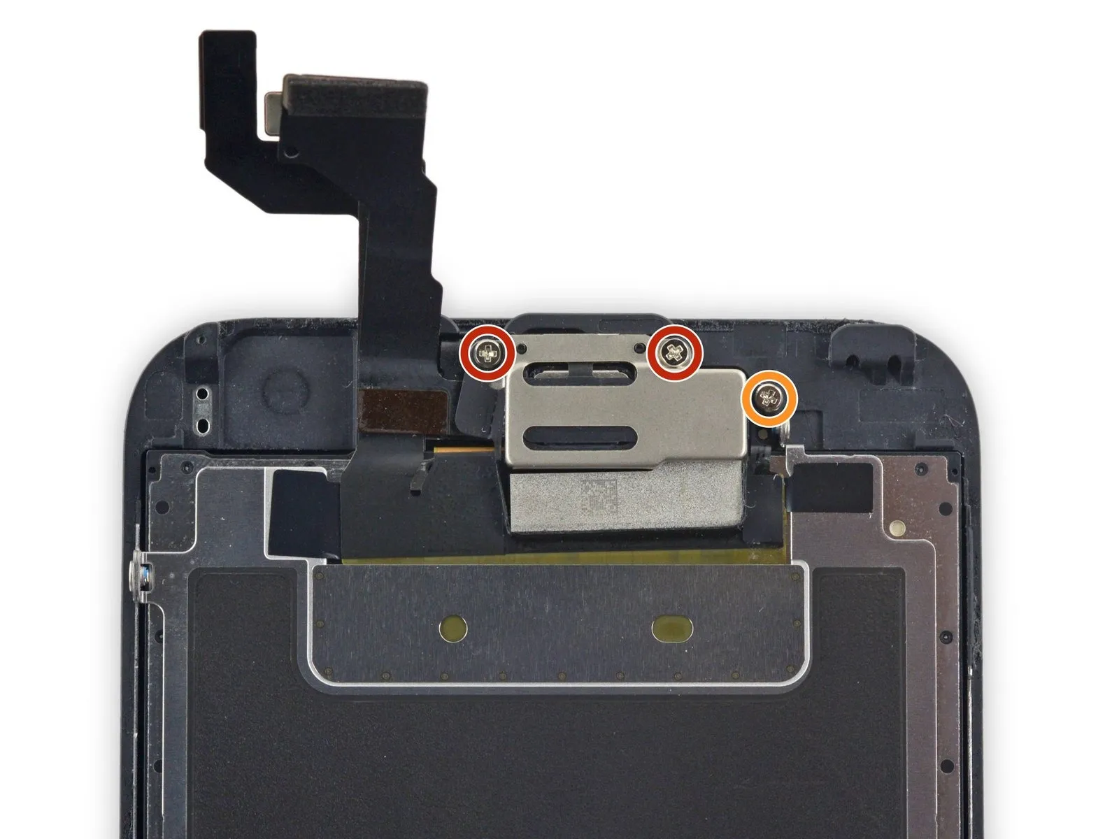
- Using the appropriate tool, detach the three.Use a Phillips screwdriver with a 1.7 mm tip.Using a Phillips #00 screwdriver, carefully fasten the home button bracket with the provided screws, ensuring each is tightened to a torque of 1.2 Nm to prevent damage.
- Applying excessive force when tightening these screws risks damaging the display's front surface.
Step 27
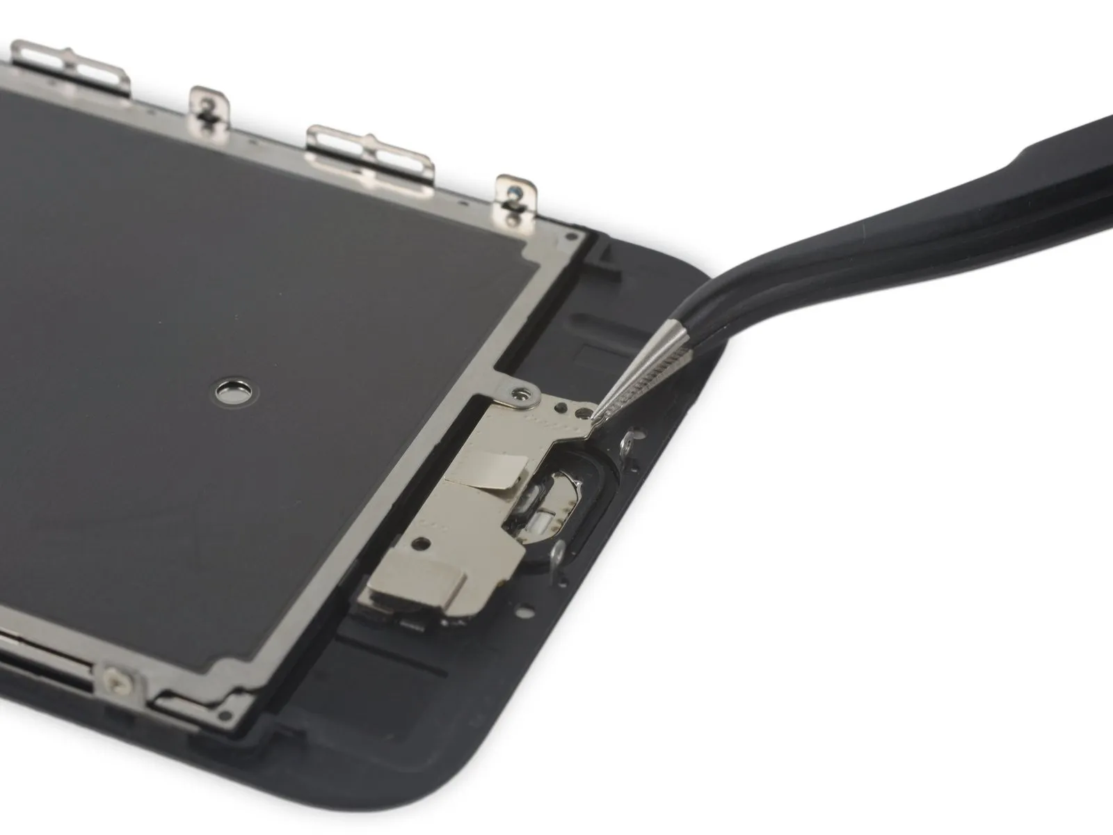
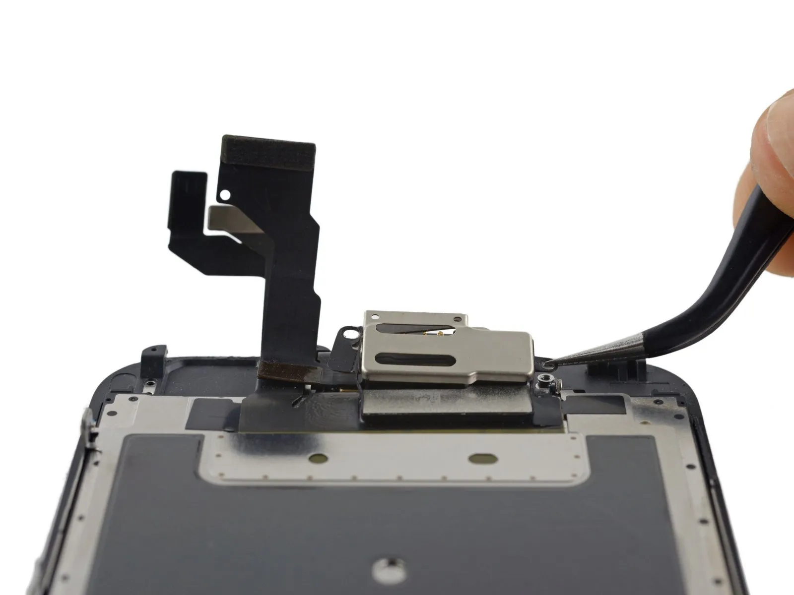
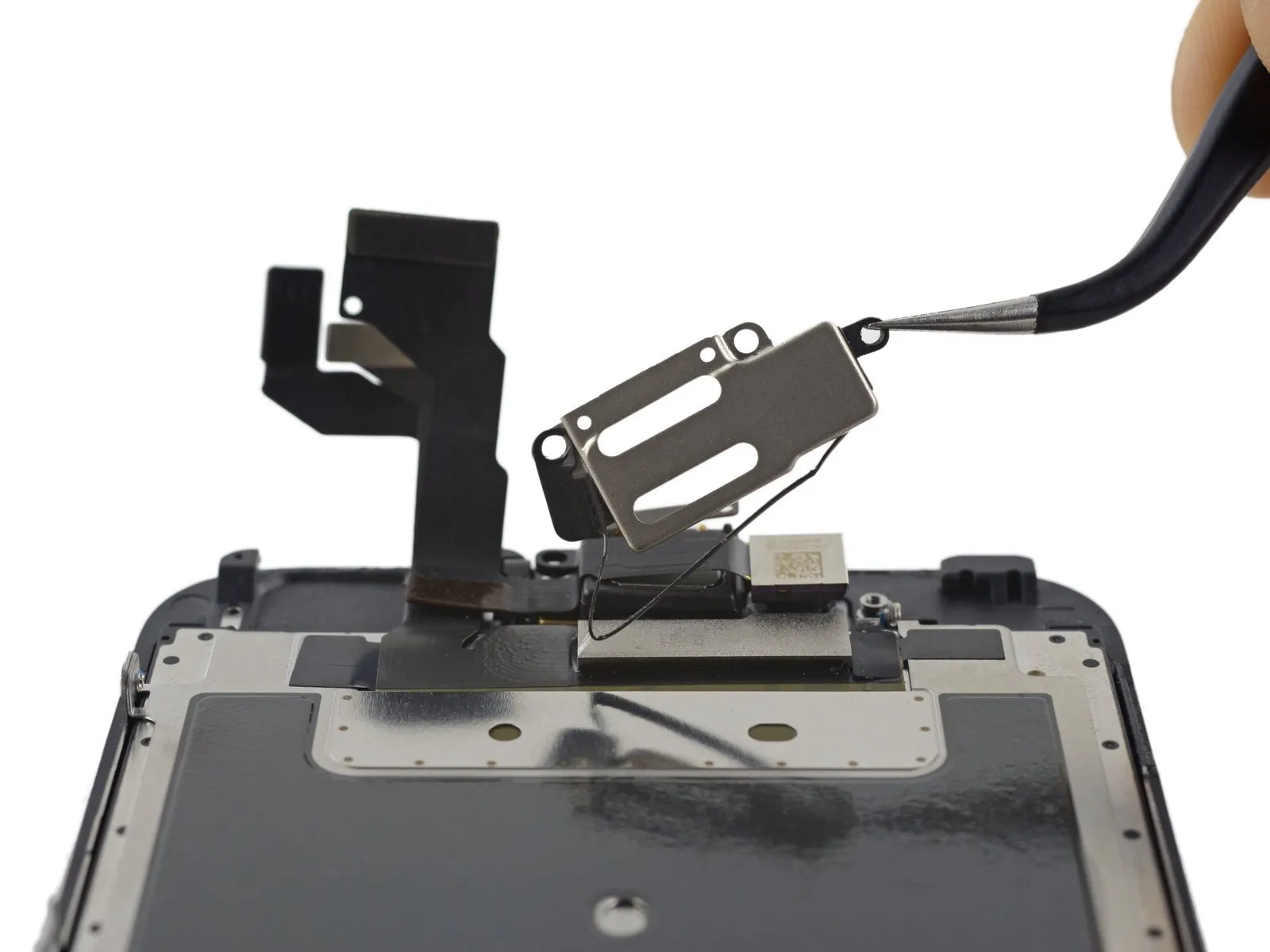
- Carefully raise the lower portion of the home button bracket, ensuring it disengages from the retaining pin located on the right-hand side.
- To detach the EMI shield, carefully move the bracket away from its position beneath it.
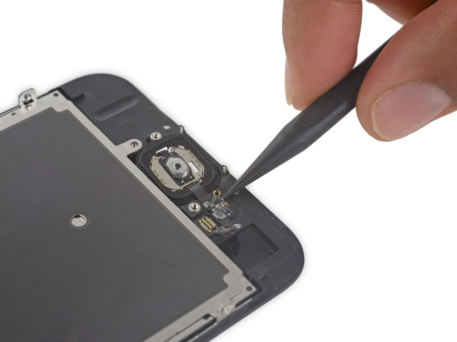
Step 28
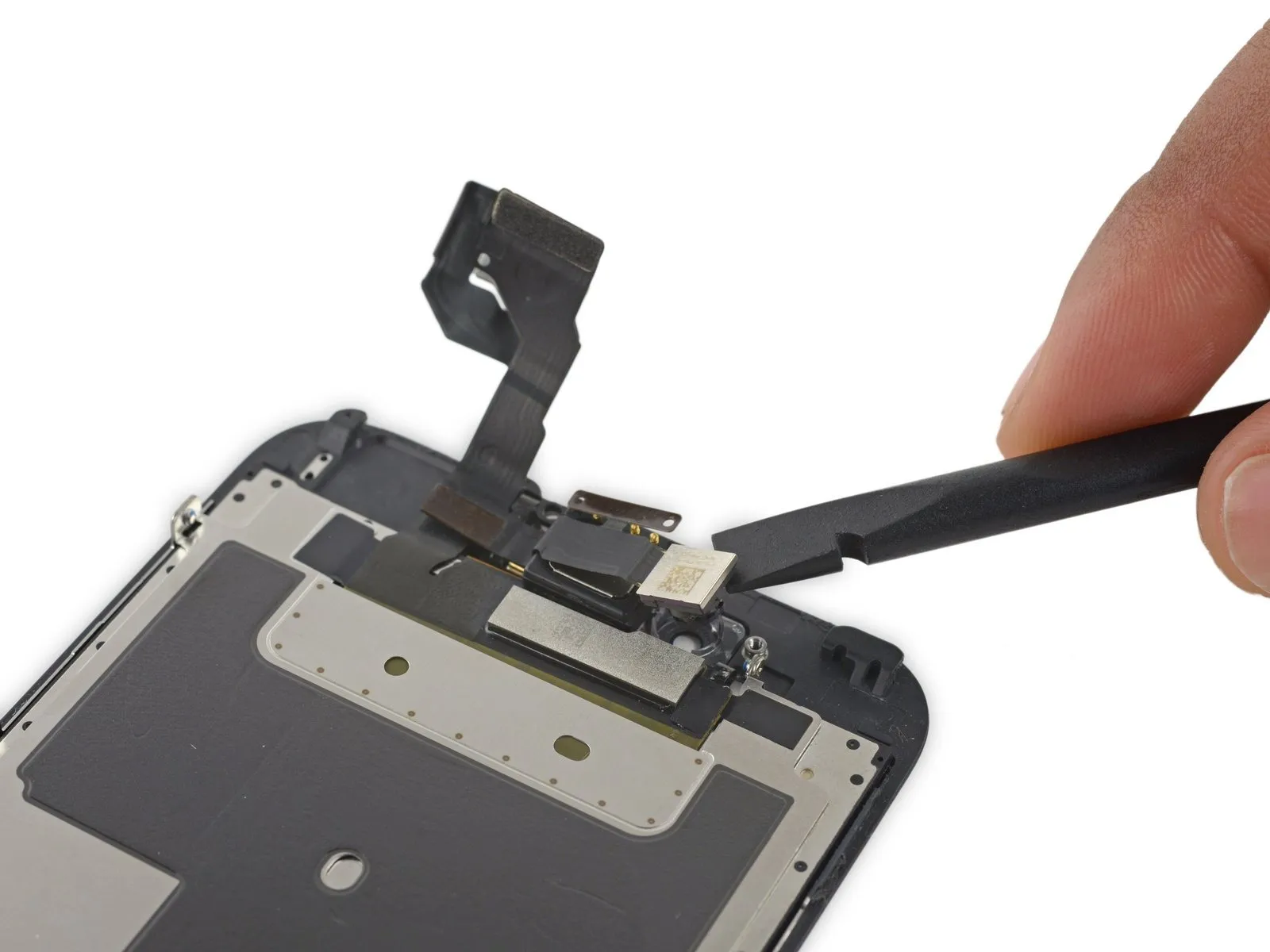
Carefully detach the home button connector from the display panel's rear by gently levering it free from its socket with a spudger.
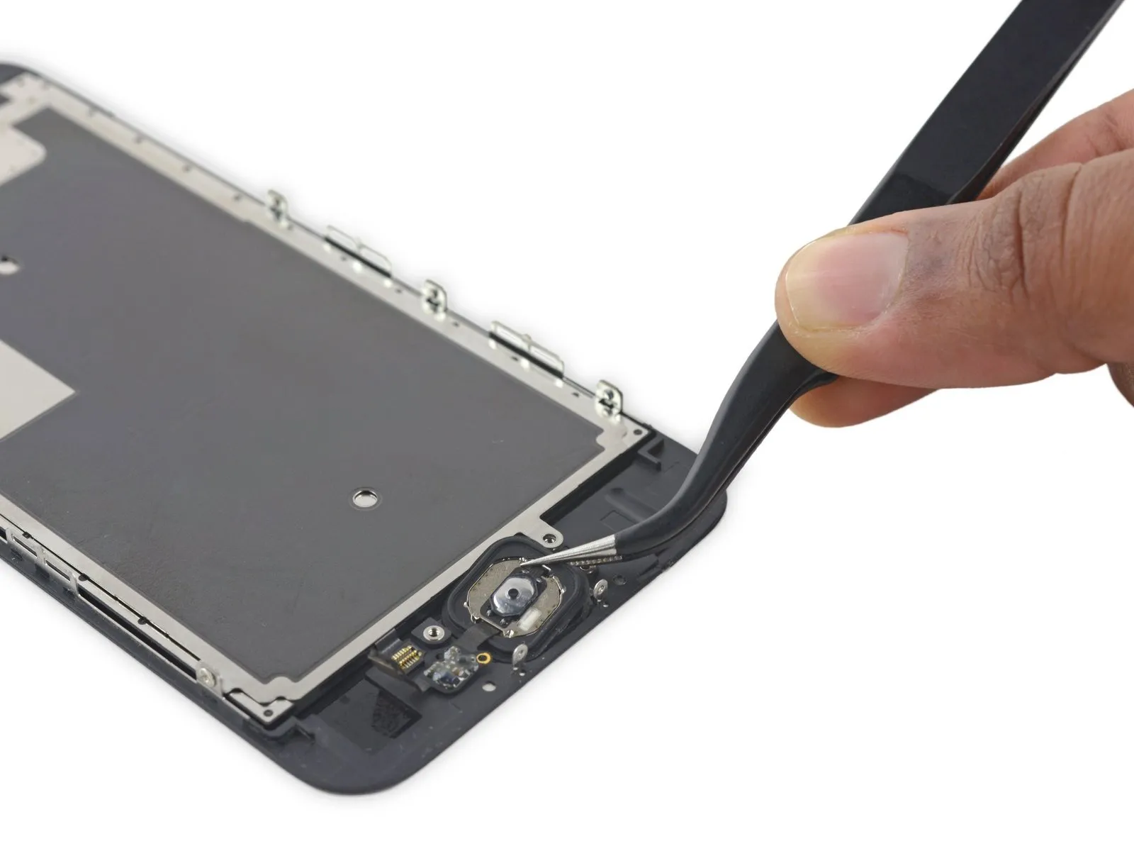
Step 29

- Due to its minimal thickness, the home button's rubber gasket is prone to tearing.
- Use a heat gun or hairdryer set to a low setting to gently warm the component.Use the iOpener to gently warm the adhesive securing the display assembly.,Apply warmth using a device that generates heated air.Using a 5/32-inch hex key, carefully tighten the retaining screw to a torque of 4.5 Nm, ensuring no damage occurs to the threads or surrounding components.Utilize a hair dryer to apply heat, ensuring it's set to a low setting and held approximately 6 inches away, to soften the adhesive securing the component.Apply a solvent to loosen the adhesive that holds the home button gasket in place.
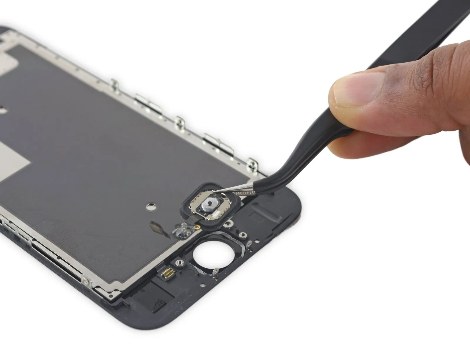
- Apply steady, upward force to the home button via the display assembly's front surface, employing your fingertip to carefully detach the rubber gasket from the front panel.
Step 30

Step 31
Step 32 | Earpiece Speaker
- Two.The required dimension is two point three millimeters.Secure with screws.
- Begin the process by executing a single action.One point nine millimeters.Fasten with a screw.
Step 33

- Carefully detach the earpiece speaker bracket, releasing the bracket gasket as it's lifted.
- Exercise caution when separating the gasket, as its thinness makes it susceptible to damage.
Step 34

- Carefully apply the flat edge of a spudger to gently dislodge the front camera assembly from its mounting.
Step 35
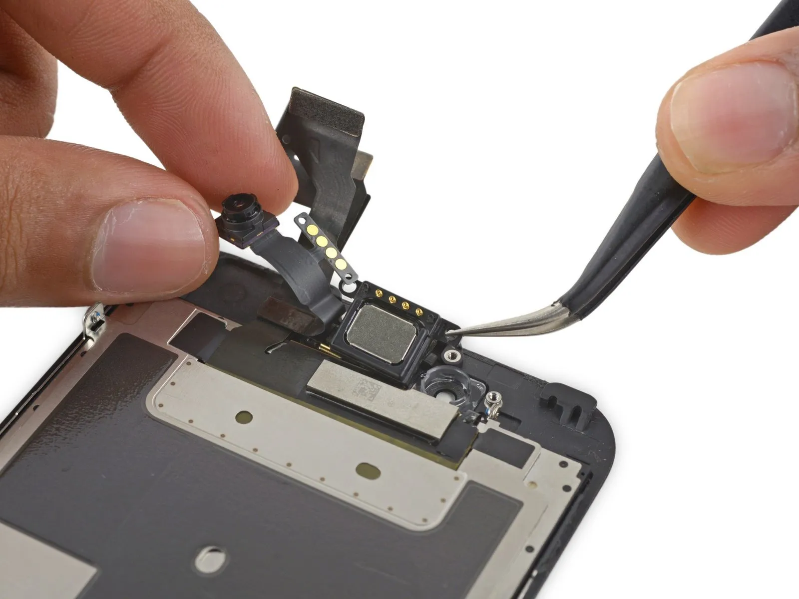
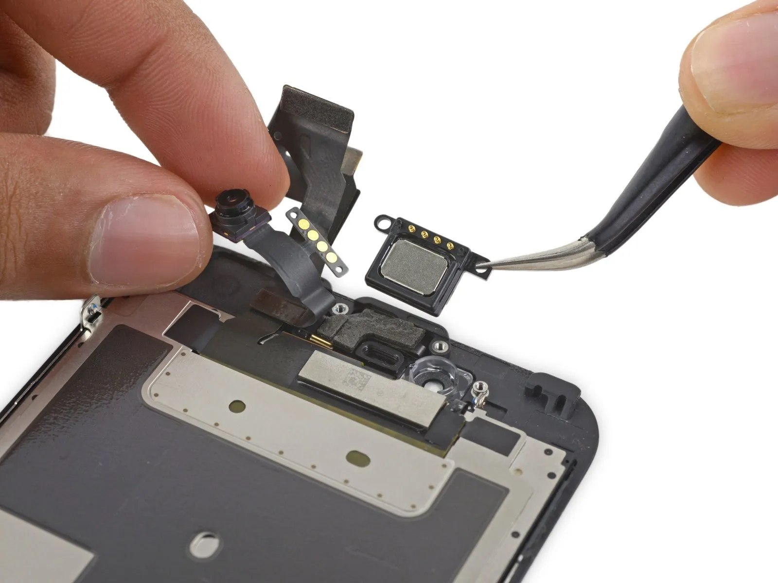
- To reach the earpiece speaker, carefully retract the front camera assembly.
- Carefully detach the earpiece speaker component.
- To prevent connection issues, avoid contact with the gold-plated connectors during speaker removal and installation, as skin oils can compromise their functionality.
- To prevent issues, clean any skin contact from the components using a small amount of isopropyl alcohol prior to reinstallation.
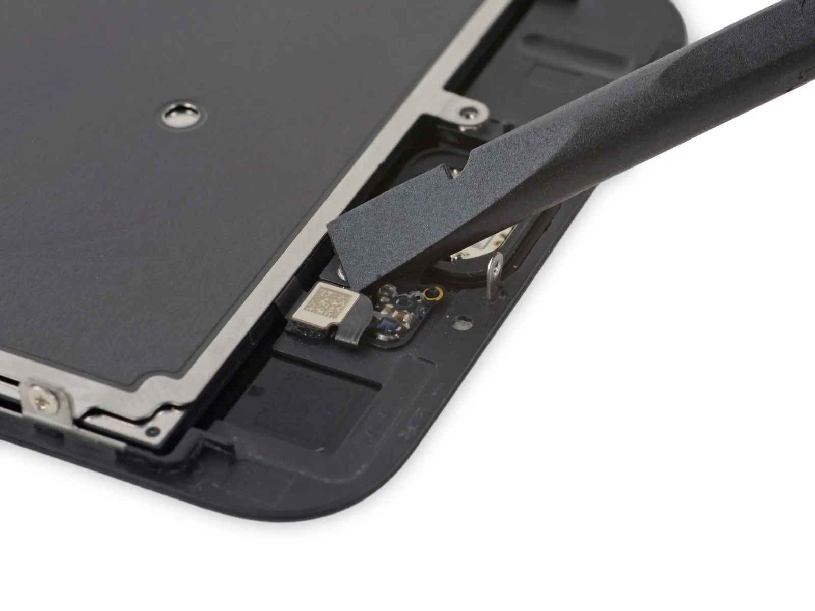
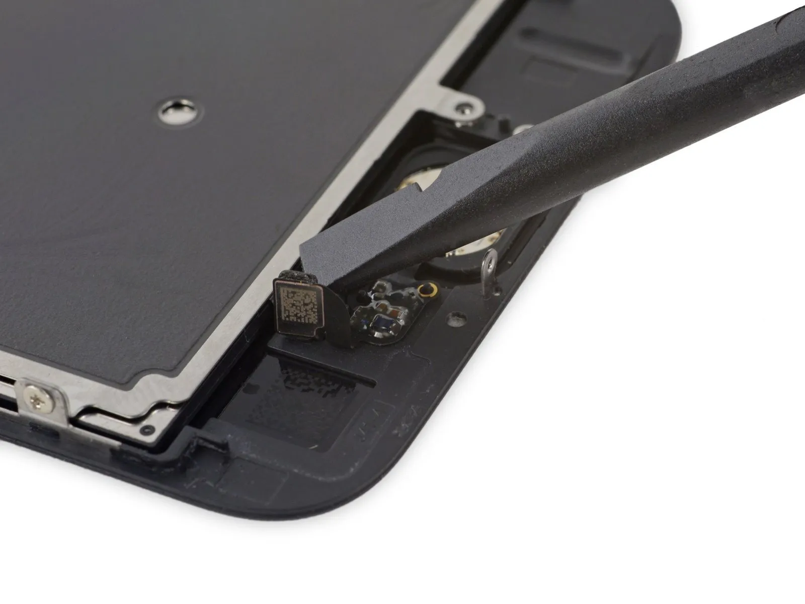
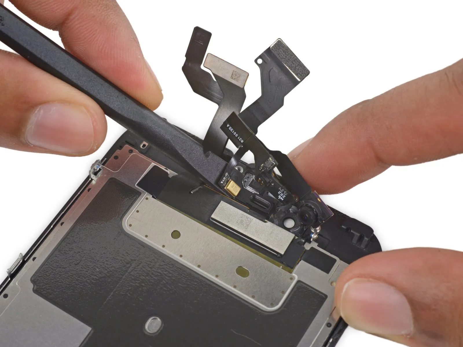
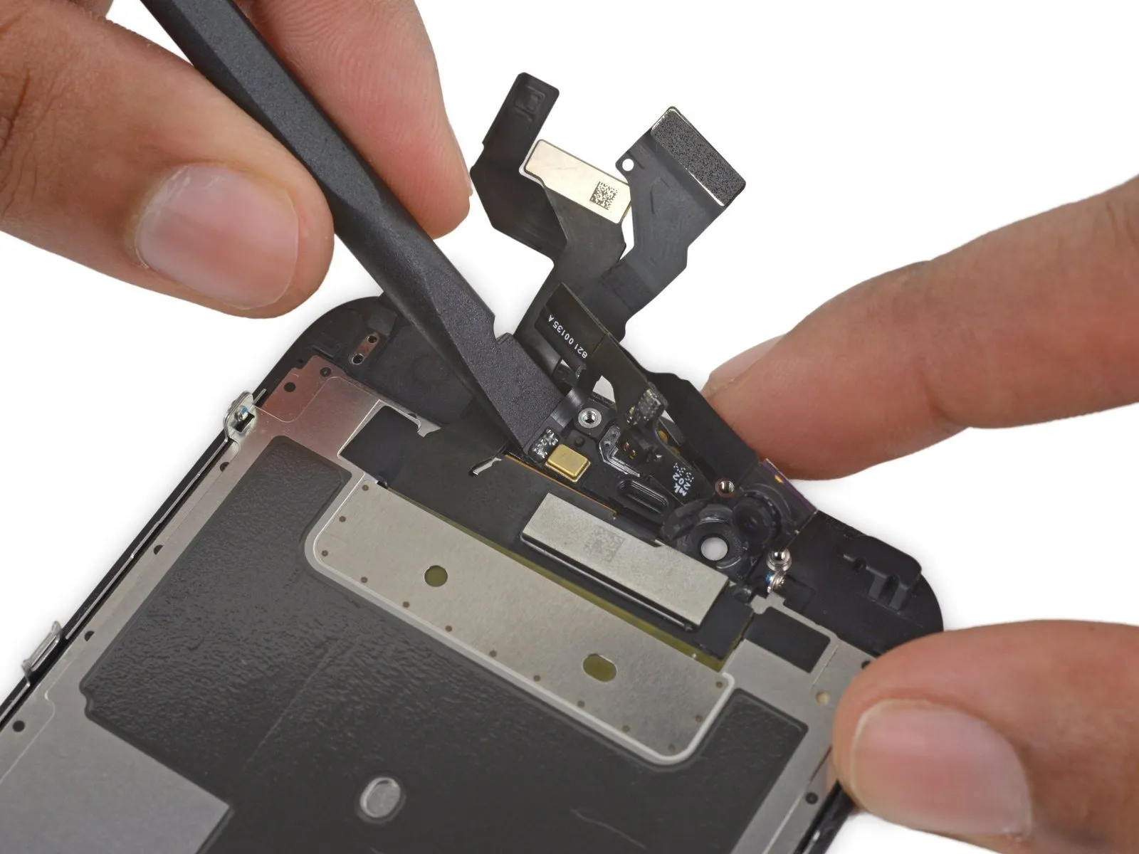
Step 36 | Front-Facing Camera and Sensor Assembly
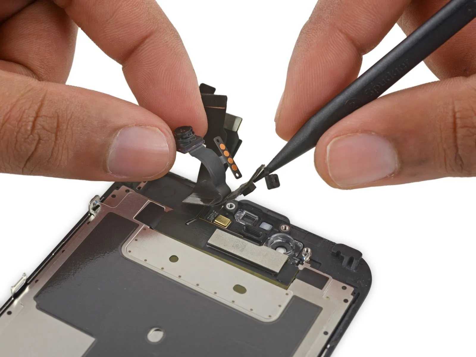

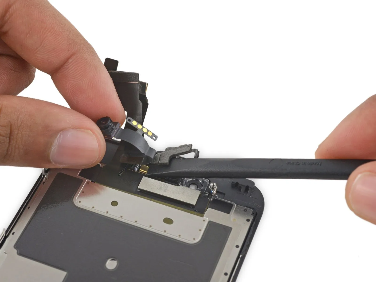
- Carefully maneuver the front-facing camera to avoid obstruction, then use the tip of a spudger to gently lift the ambient-light sensor from its seating within the front panel.
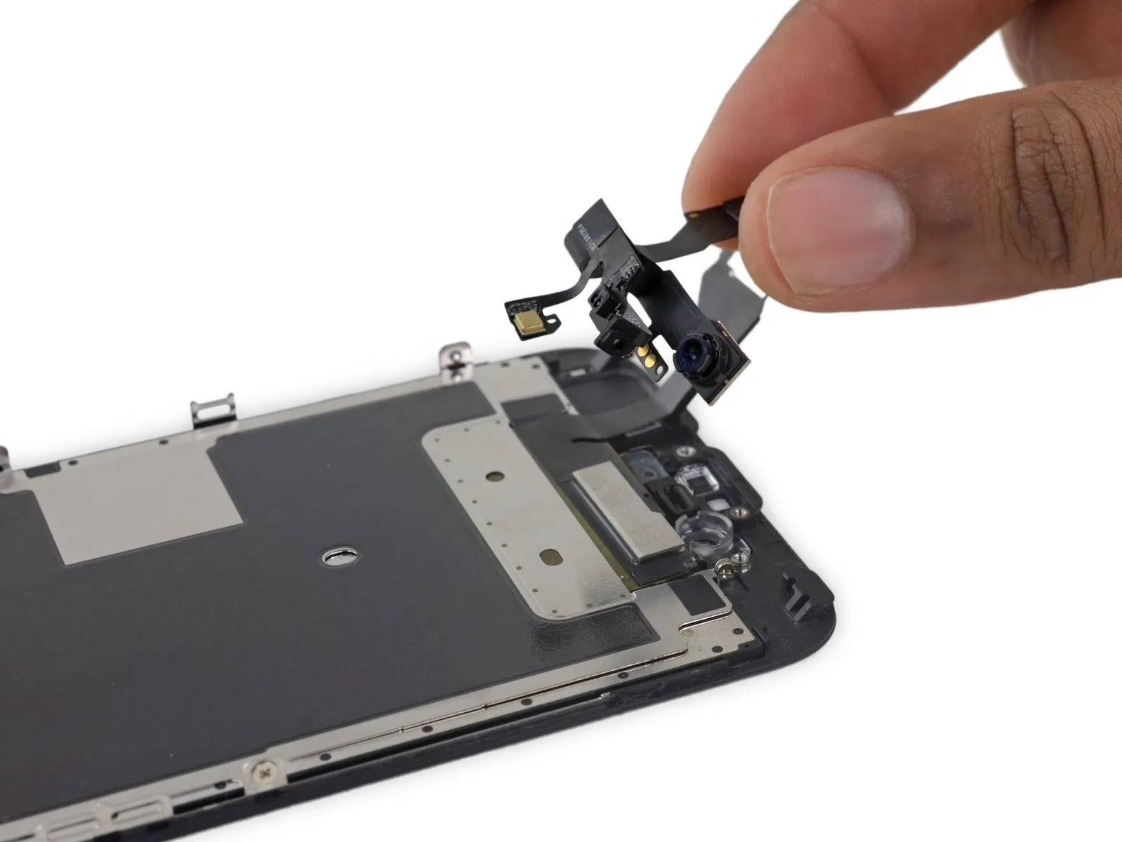
Step 37

Step 38
Step 39
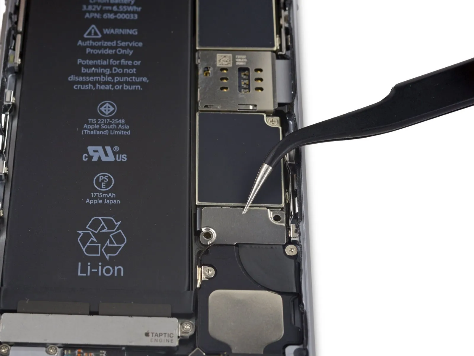
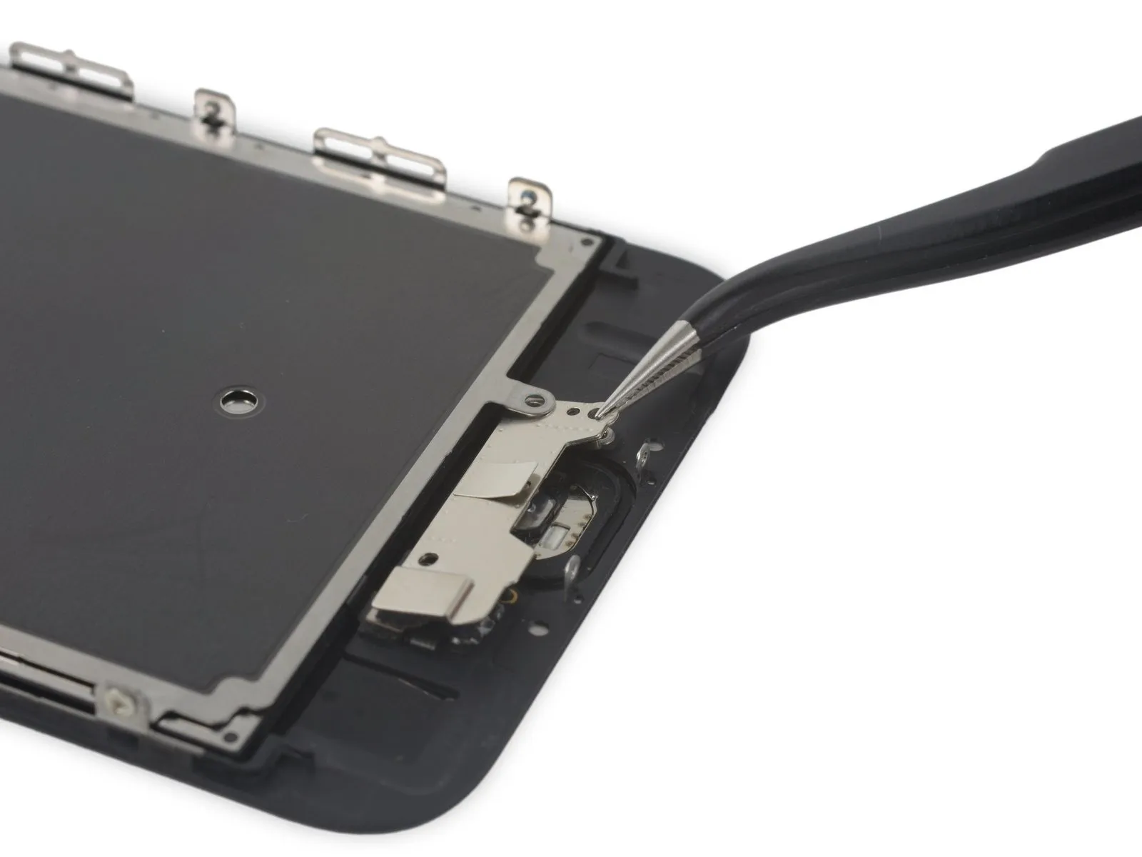
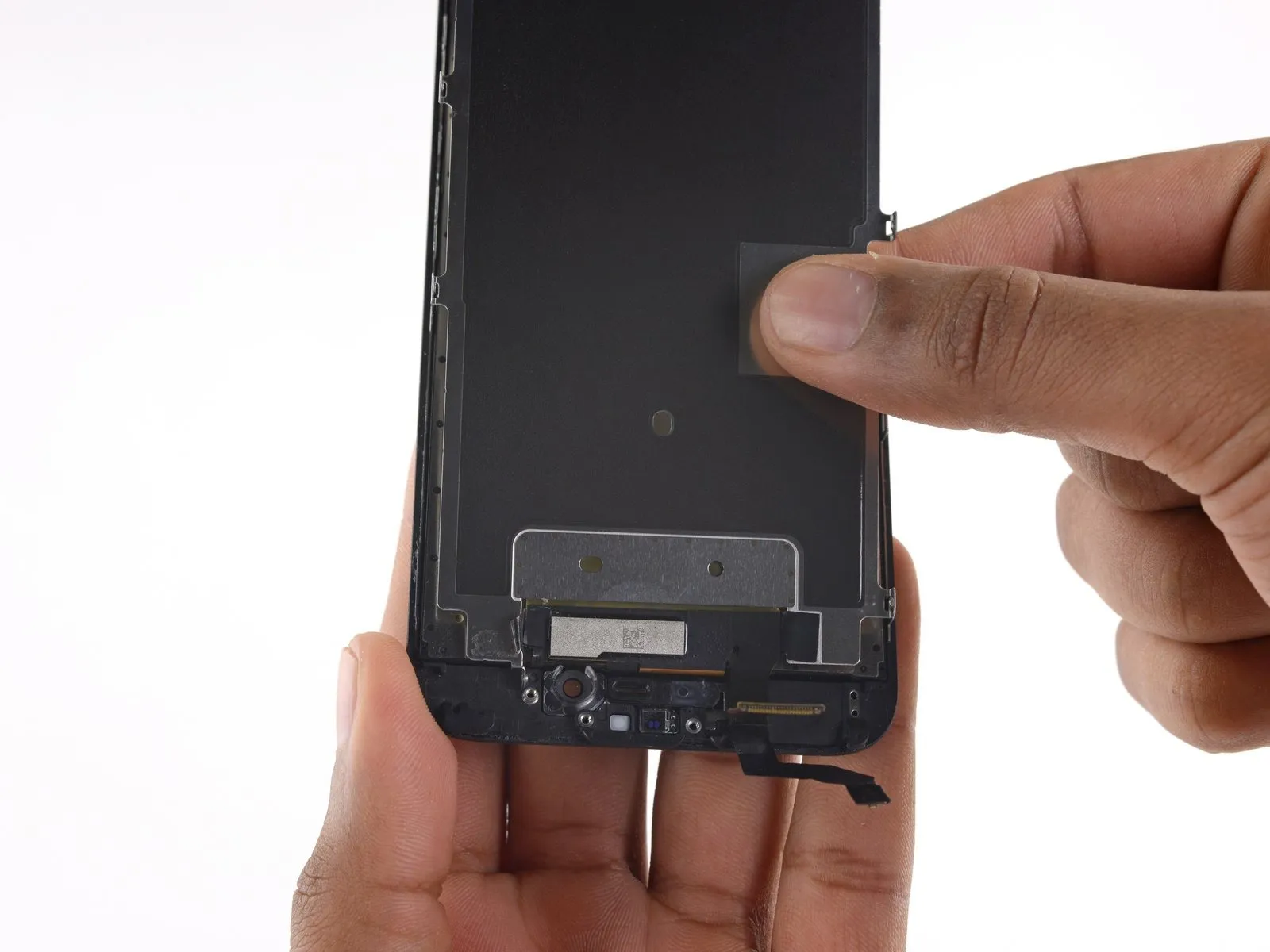
Step 40 | Display EMI Shield

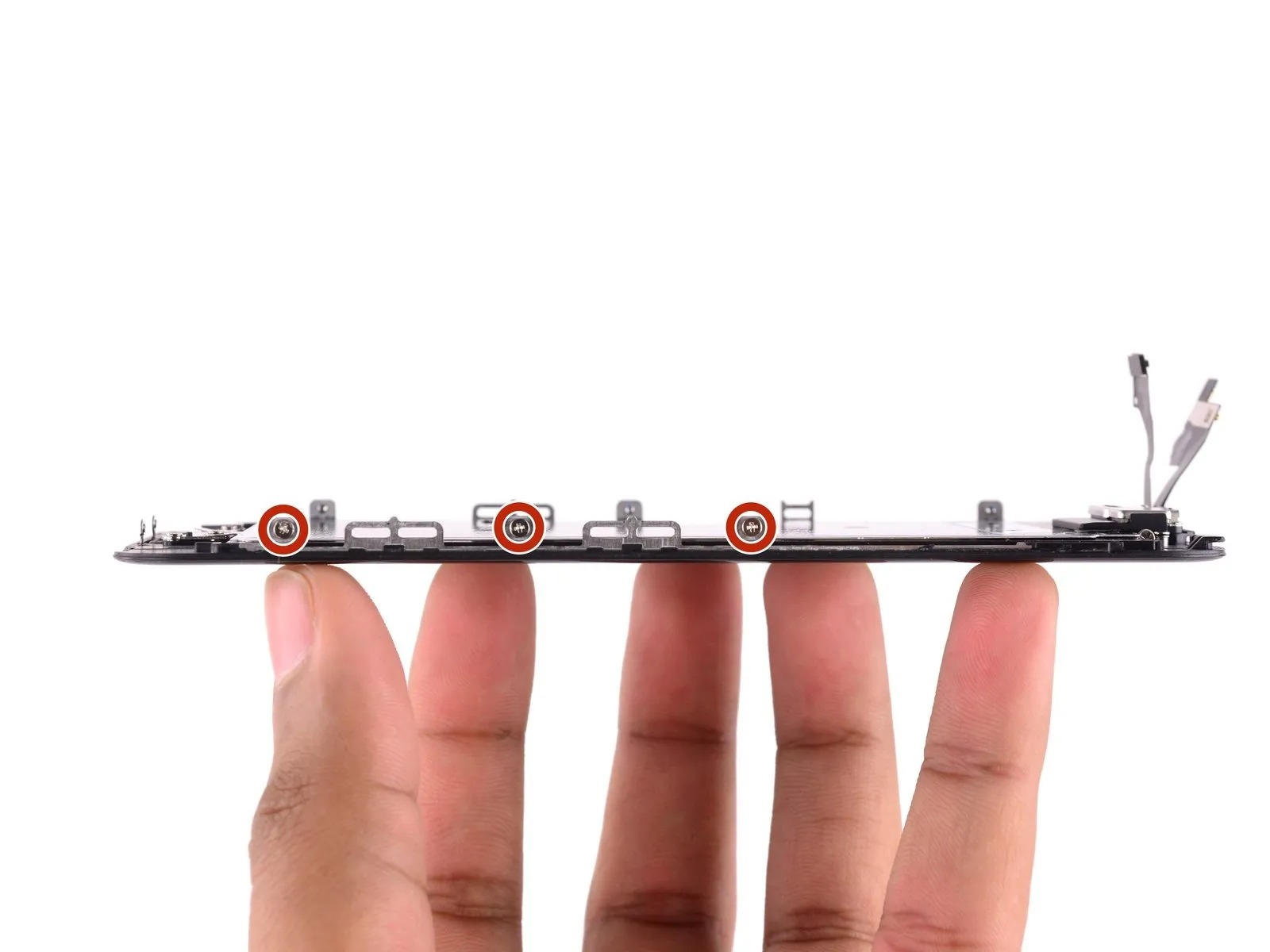
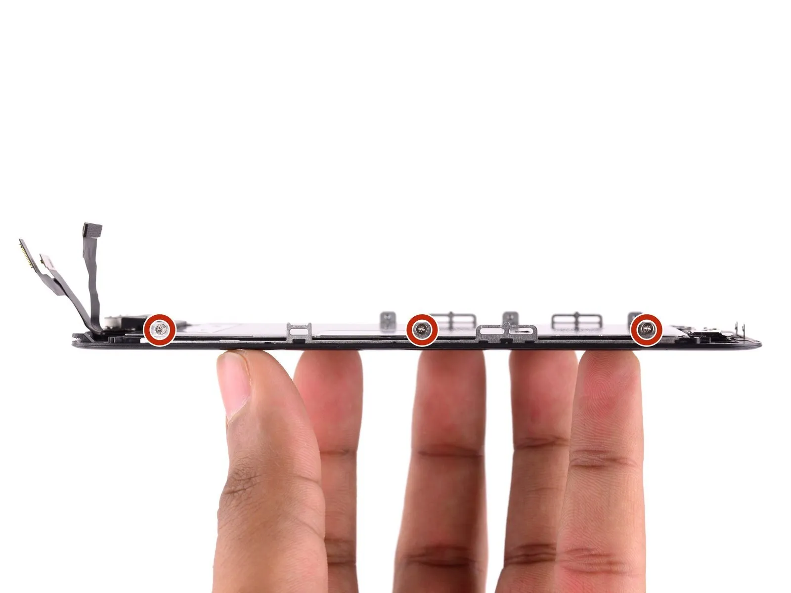
- Secure the display panel with three screws along its left side and three screws along its right side.
- Locate the screw, positioned 1.5 centimeters inward from the right screen edge.
Step 41


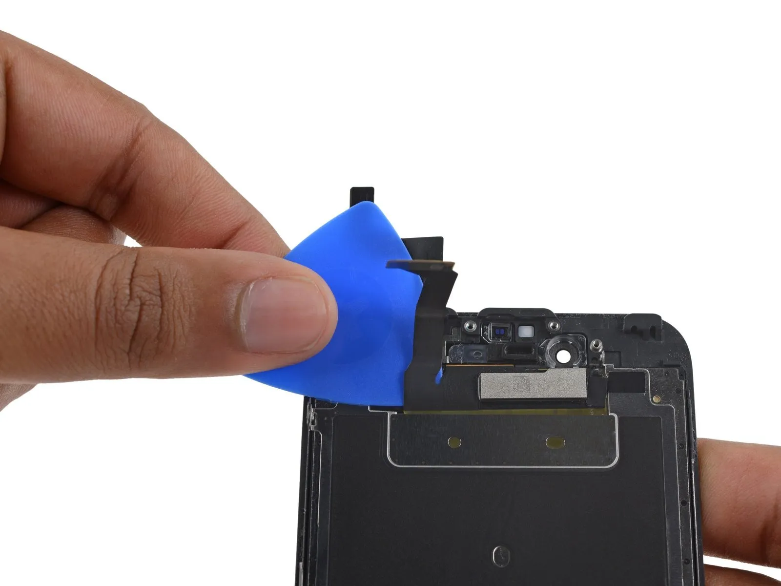
- Using appropriate safety precautions, gather the necessary materials and tools, then ensure the specified components are ready for the subsequent steps.Use the iOpener.Carefully position the tool across the upper edge of the device to gently separate the electromagnetic interference shield from the front panel, releasing the adhesive securing them together.
Allow one minute to pass, then carefully slide a pick into the gap separating the display data cable from the adhesive tape.
Using gentle pressure, depress the pick until its tip aligns level with the top surface of the EMI shield.
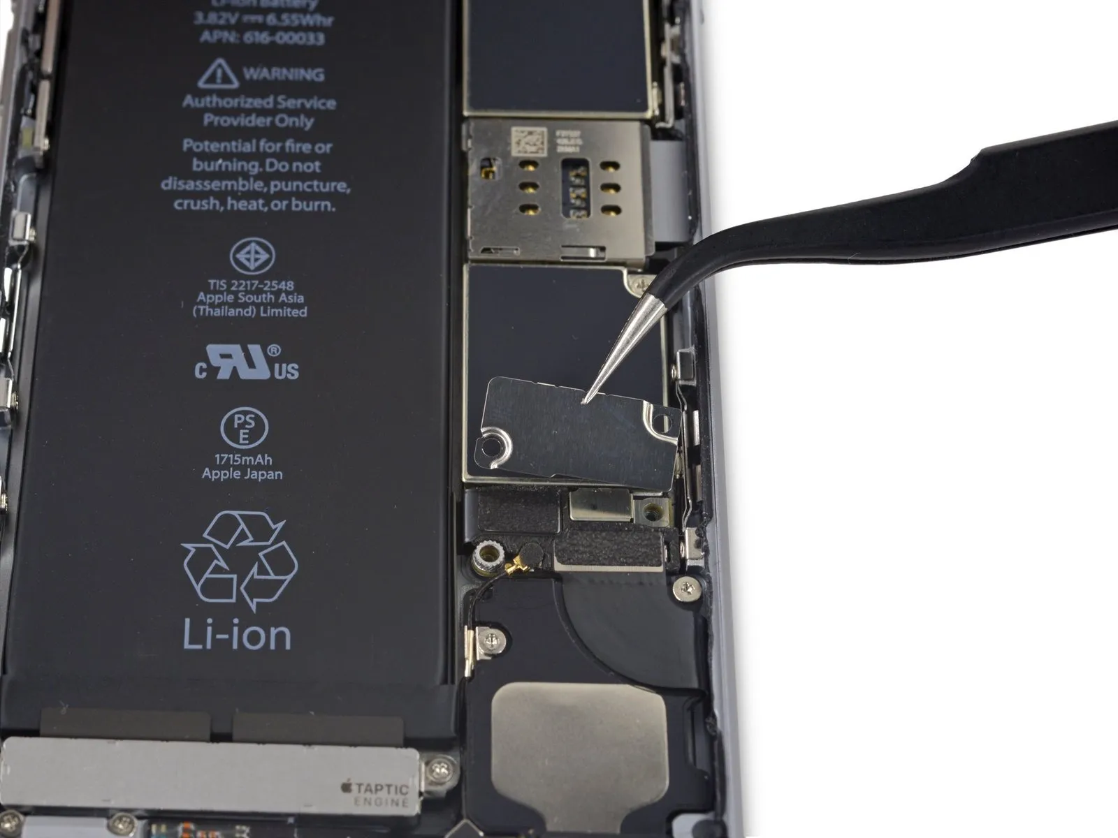
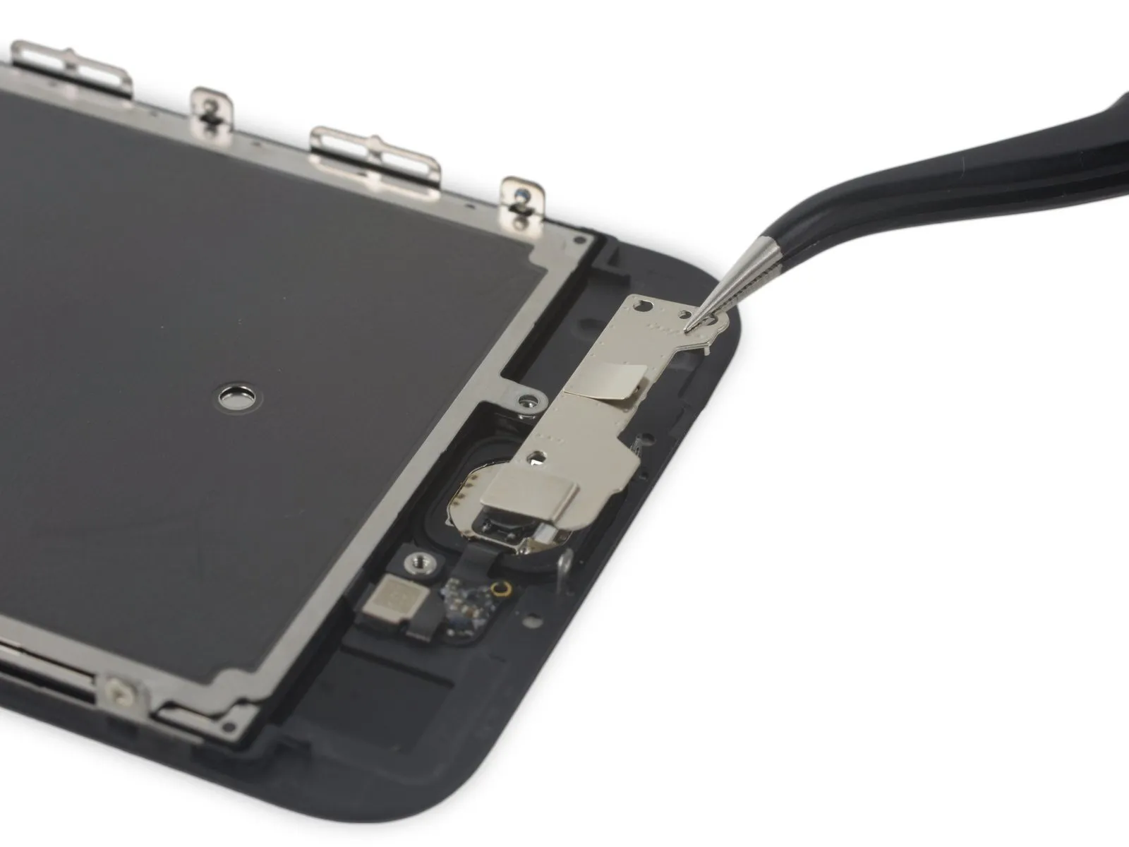
Step 42
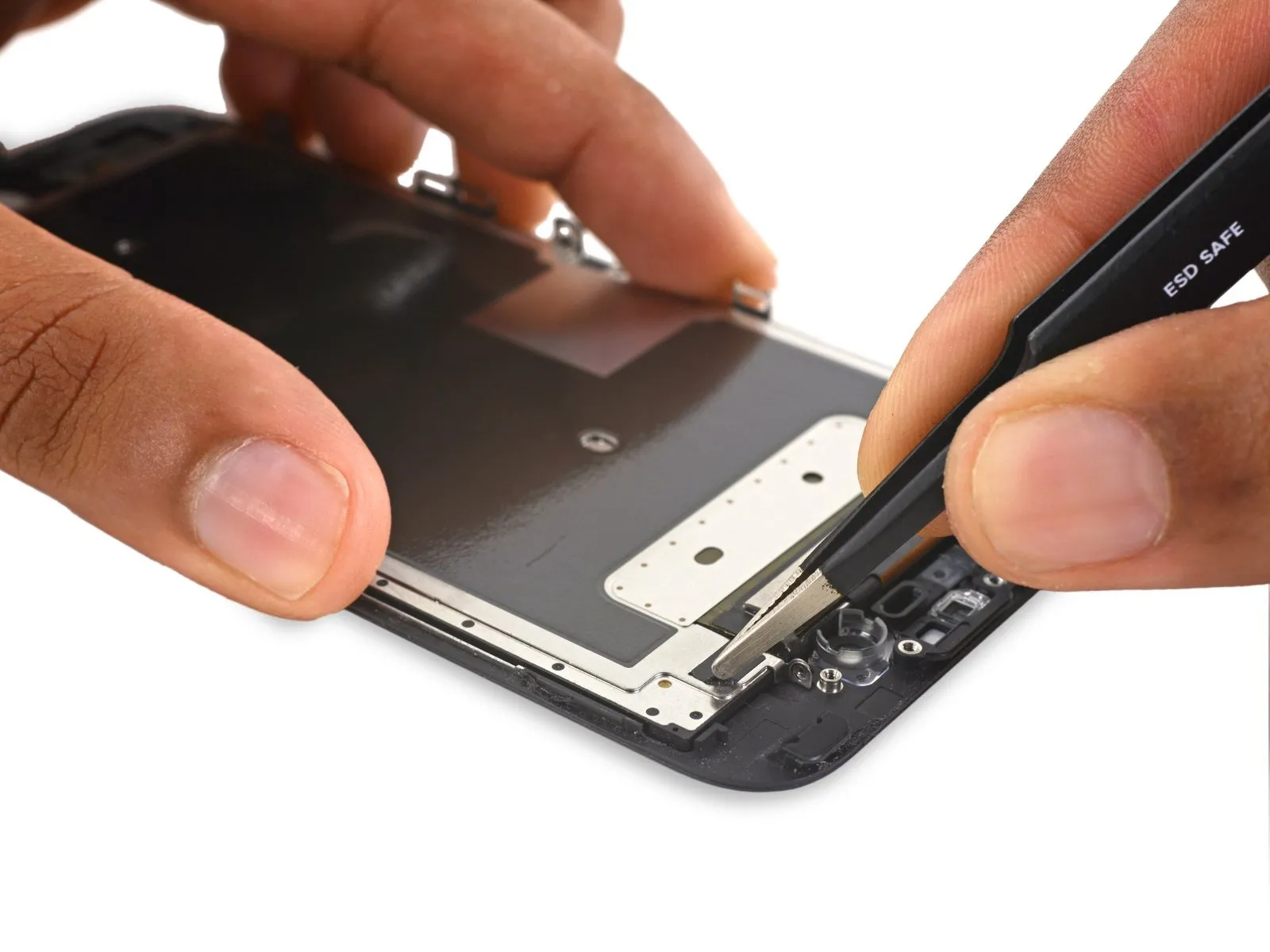
- Carefully lift the electromagnetic interference shield tape, positioned close to the front-facing camera assembly, utilizing tweezers.
Step 43

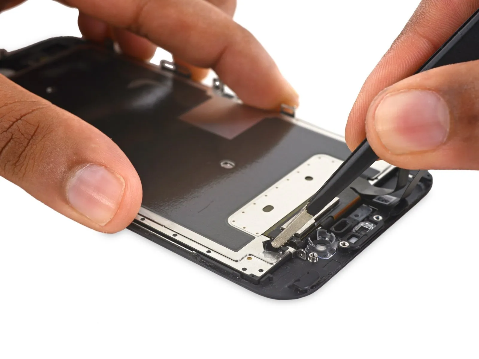
- Carefully detach the electromagnetic interference shield.
Position the EMI shield, ensuring the cutout visible in the center bottom aligns directly above the display cable assembly, then slide the provided tape into place behind the shield.
Step 44 | LCD and Digitizer

The display panel and touch layer are the only components still attached.