iPhone 6s Lightning Connector Assembly Replacement
Despite cleaning attempts, a faulty Lightning port may require replacement; proceed with the following instructions.The flexible cable connecting to the Lightning portWithin an iPhone, the flex cable, encompassing the display, digitizer, and front sensor assembly, must be handled with care.USB-C connectorThe device incorporates a headphone jack, two microphones, and spring-loaded electrical contacts securing the Taptic Engine and loudspeaker.
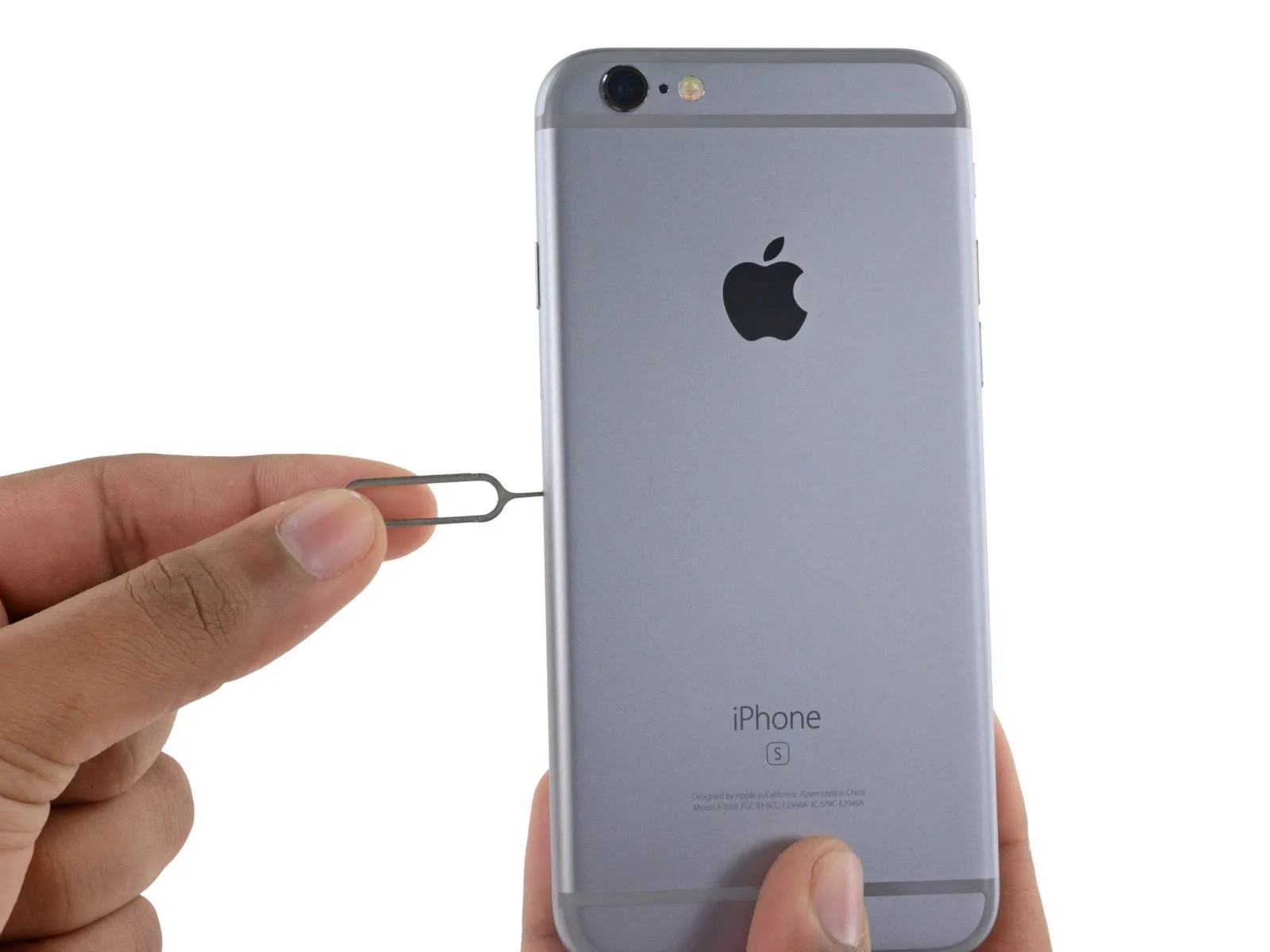
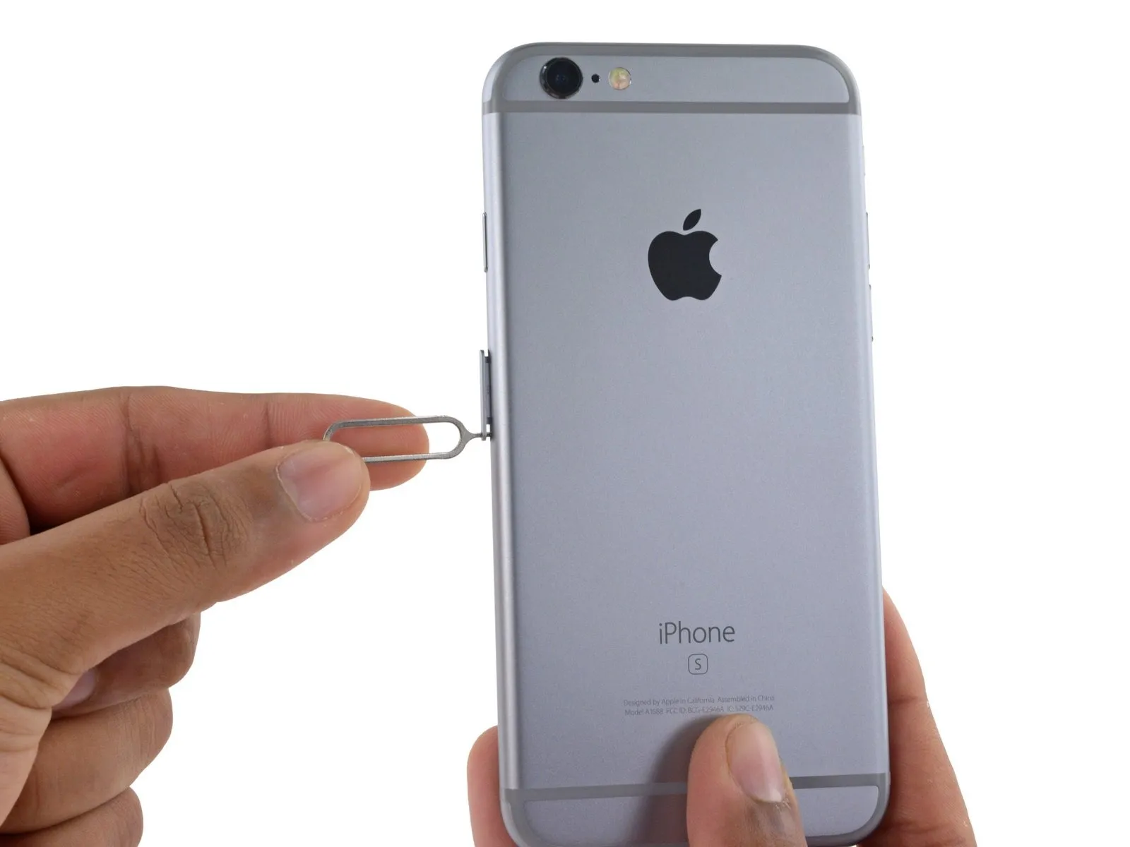
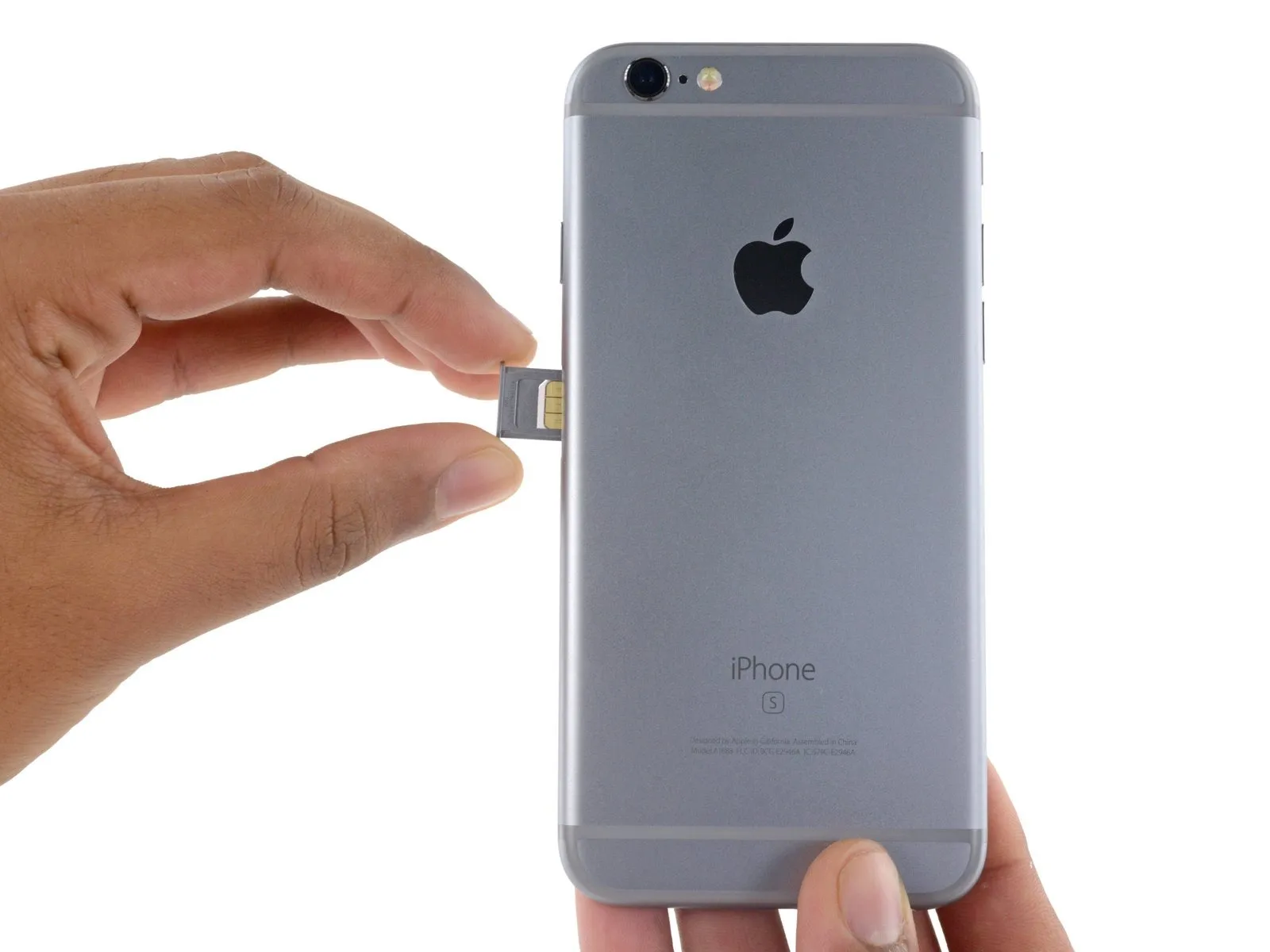
Step 1 | SIM Tray
Step 2
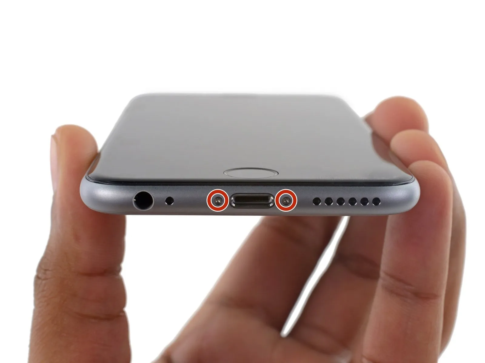
Step 3 | Pentalobe Screws
Step 4 | Anti-Clamp instructions


Step 5


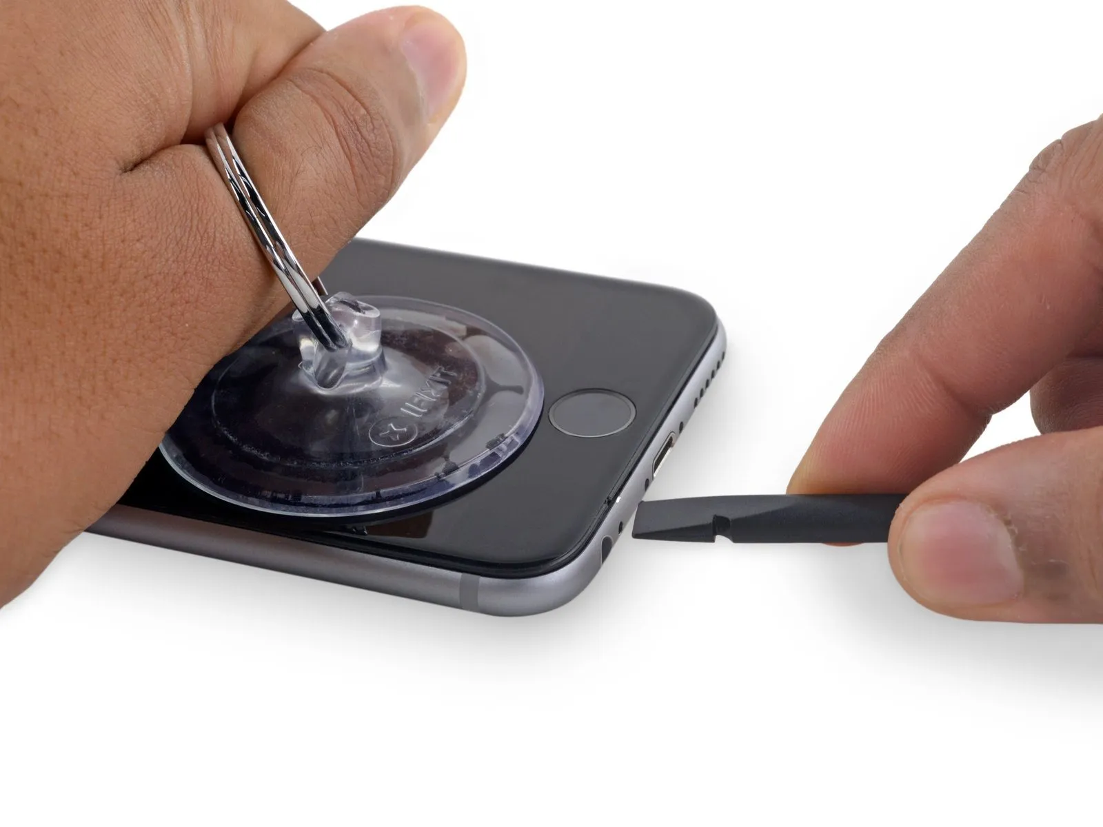
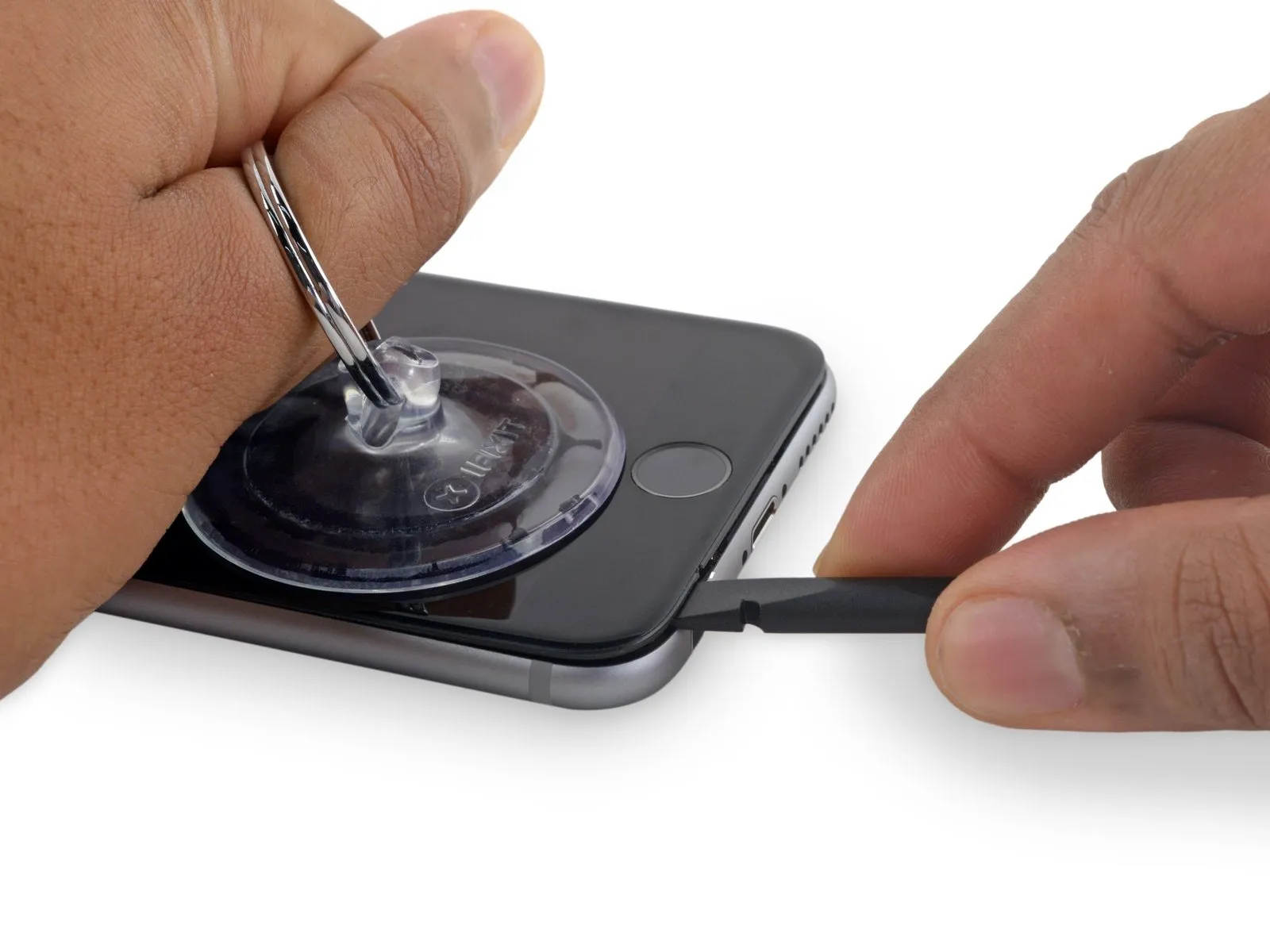
Step 6 | Opening Procedure
- Using either an iOpener or a hair dryer, gently warm the bottom perimeter of the iPhone's casing with moderate heat for approximately 60 seconds.
- Applying heat will loosen the adhesive that holds the display in place, facilitating separation.
Step 7
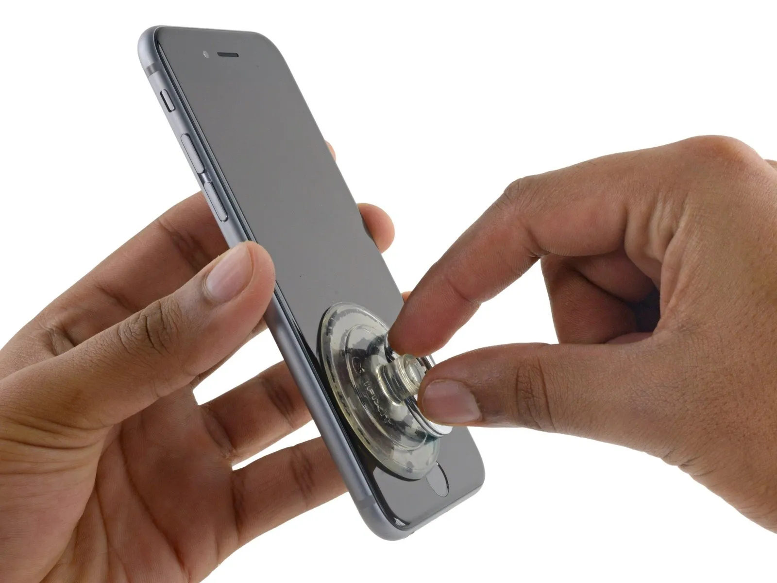
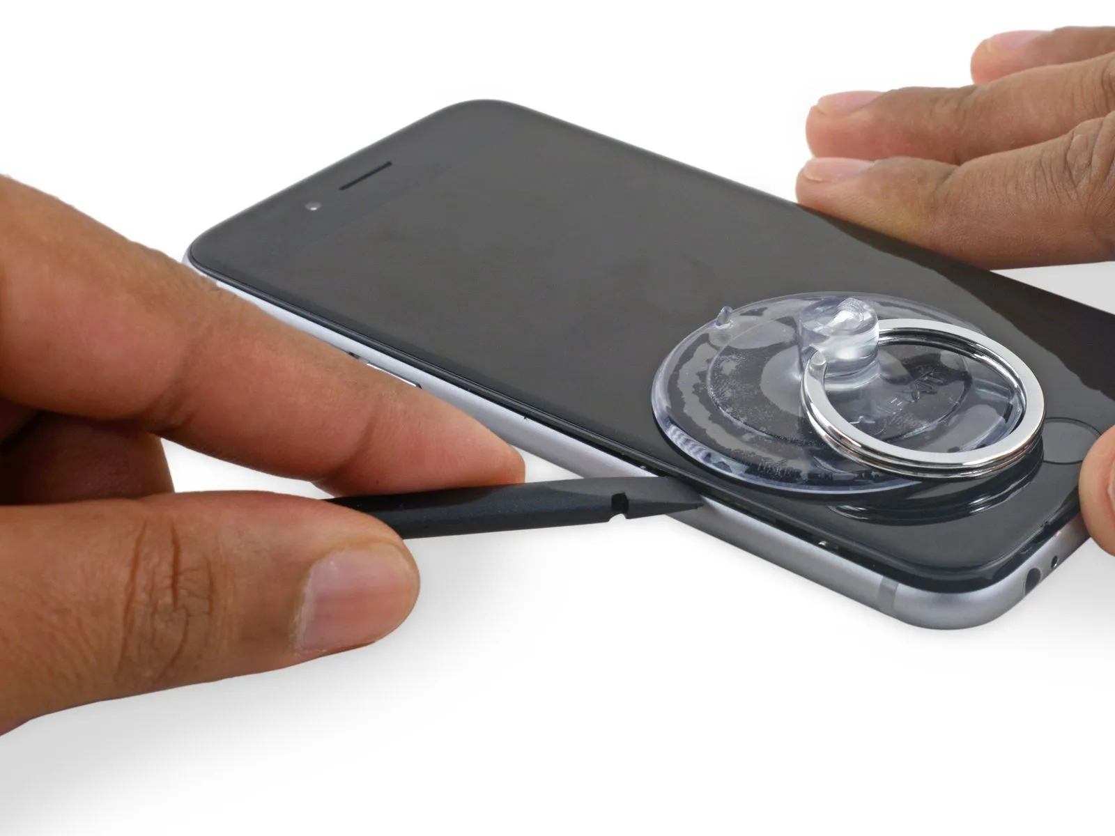
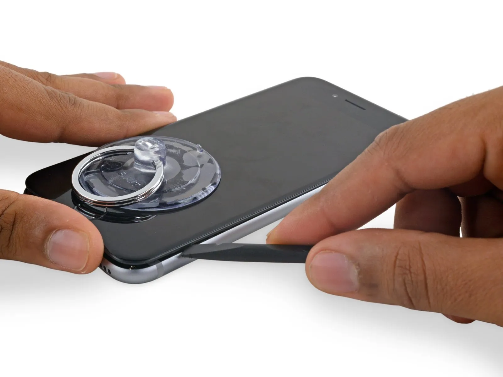
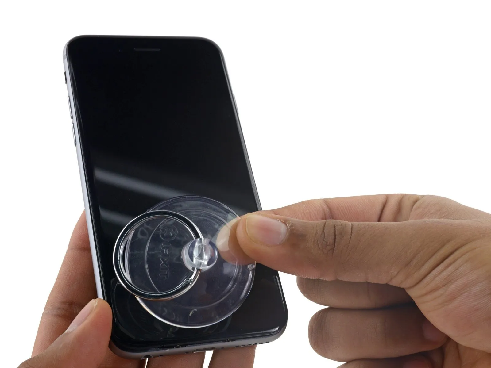
- Using a suction cup, secure its surface to the display assembly's lower left corner.
- Avoid positioning the suction cup directly on the home button.
- To facilitate suction cup attachment when the display has severe cracking, apply a sheet of clear packing tape across the damaged area; as an alternative, a robust adhesive tape can be substituted for the suction cup. As a last resort, secure the suction cup directly to the fractured screen using superglue.
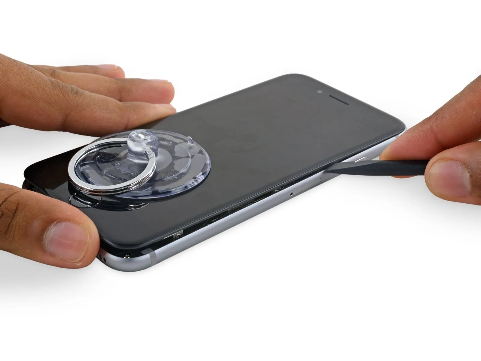
Step 8
- Exercise caution and use steady, even pressure during installation; the display unit's fit is considerably snugger than typical device components and is secured with adhesive.
- To avoid display assembly damage, use minimal force when separating it from the rear case; the goal is to establish a narrow separation.
- To ease separation of the display from the frame, apply warmth to the front surface of the iPhone with an iOpener, hair dryer, or heat gun until the exterior reaches a temperature just beyond comfortable touch, which will loosen the adhesive bonds along the perimeter.
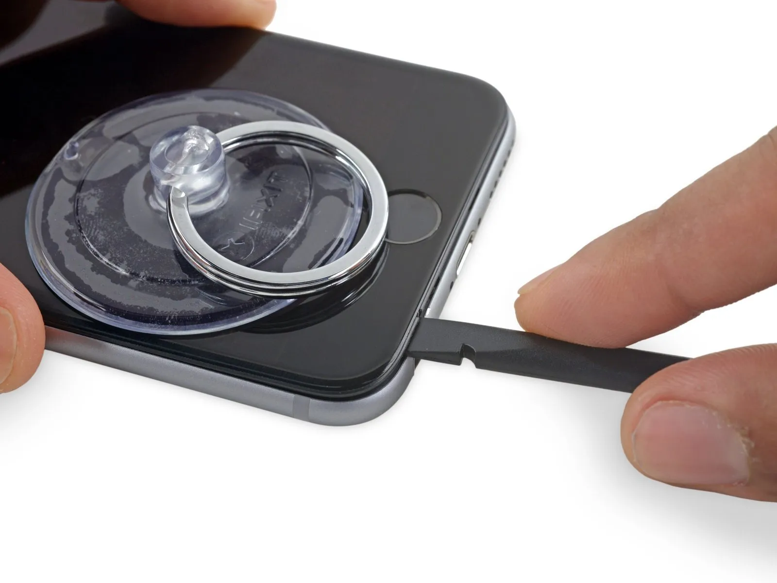
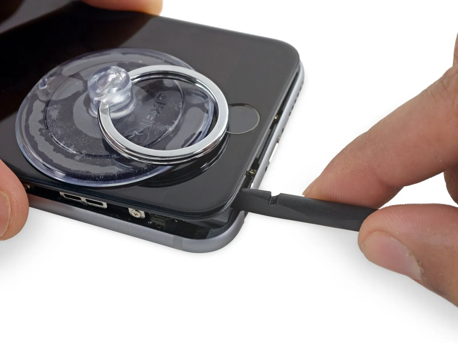
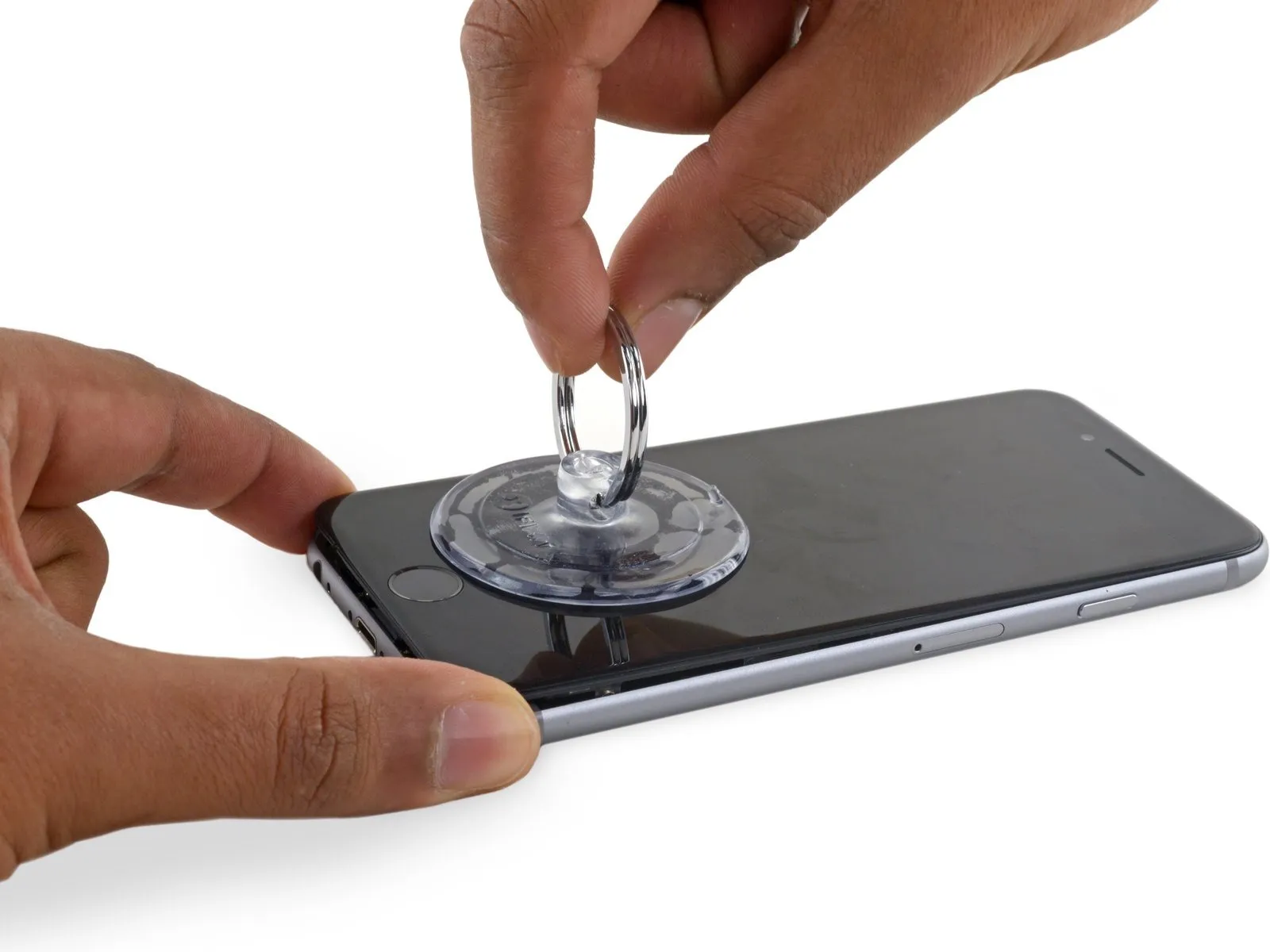
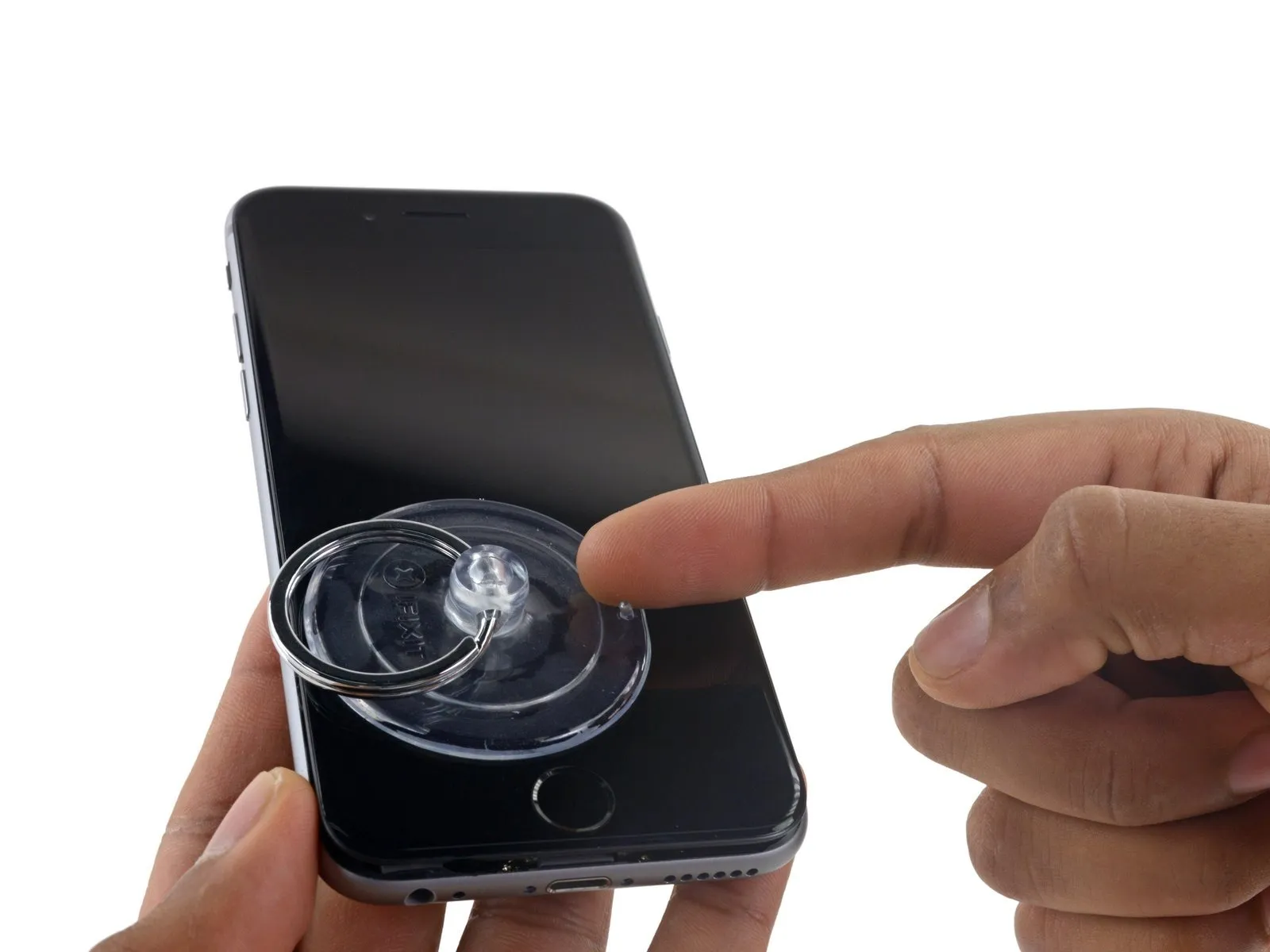
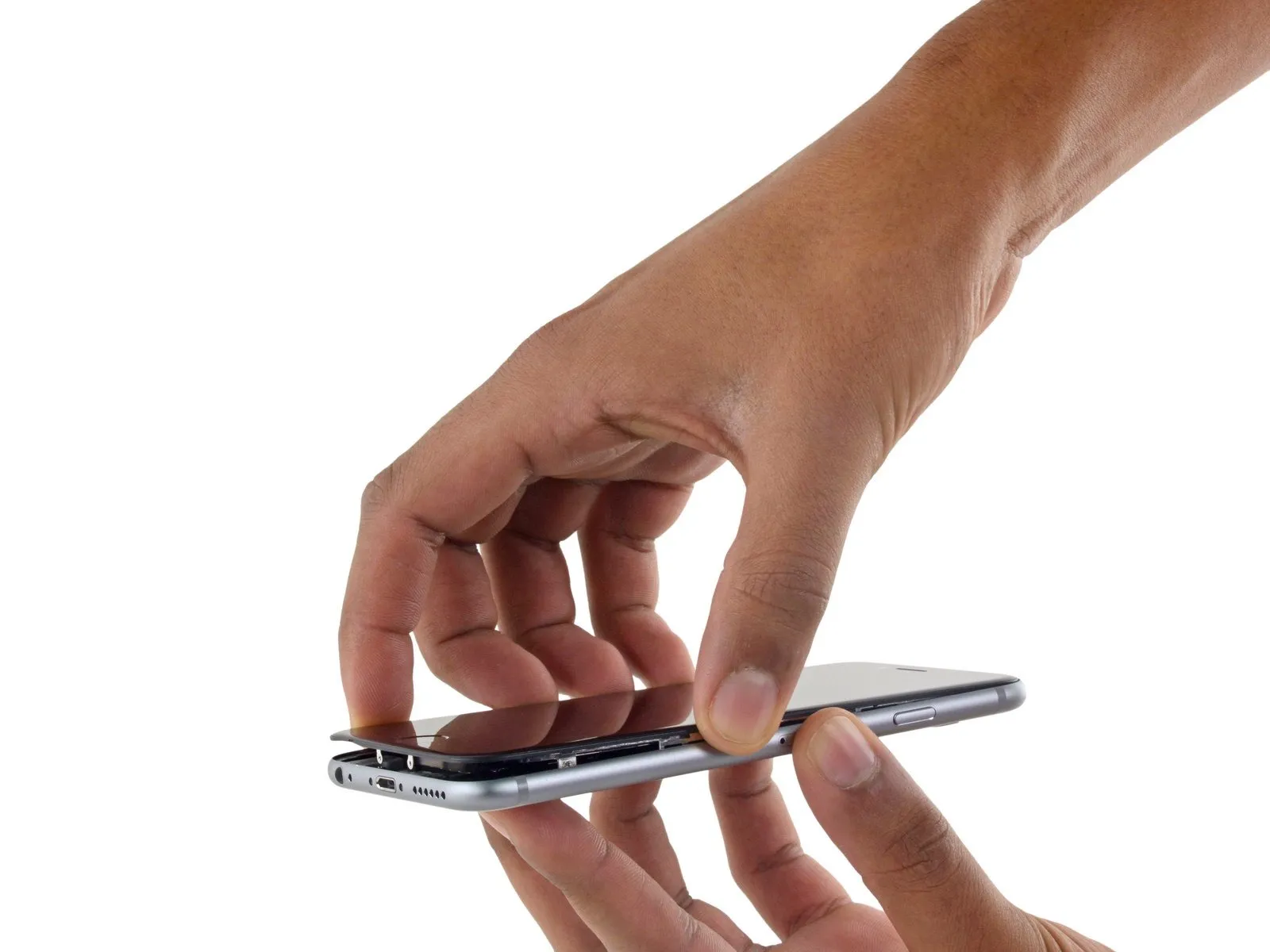
Step 9
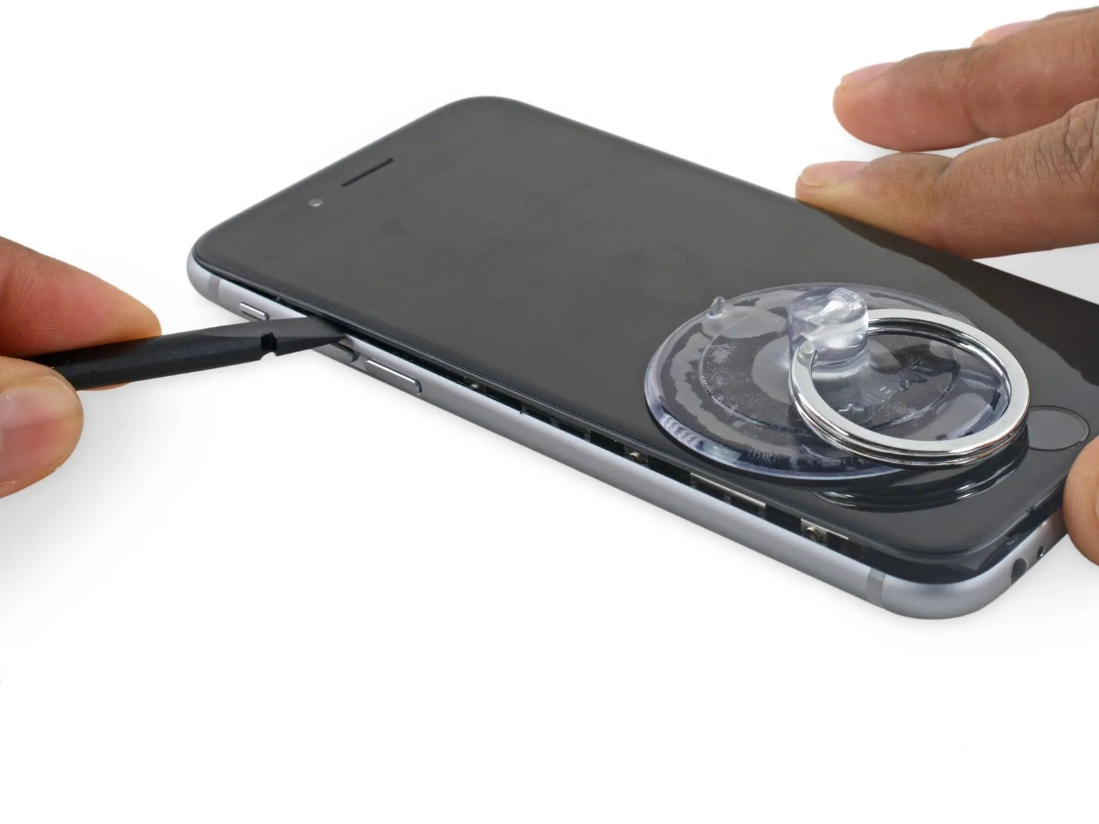
- Carefully start separating the phone's casing by inserting a prying tool into the indentation located on the bottom of the display, directly above the headphone jack, as this area minimizes the risk of damage.
- Position the straight side of the tool against.Use a plastic pry tool, often referred to as a spudger, to avoid scratching surfaces.Position the tool precisely within the space separating the display assembly from the back cover, located immediately above the headphone connector.
Step 10
Rotate theUse a plastic pry tool, often referred to as a spudger.Carefully increase the separation between the front panel assembly and the main phone body.
Step 11
- Using the tool's straight edge, carefully guide it into the designated space.Use a plastic pry tool, often referred to as a spudger.Locate the component on the device's left lateral edge, positioned in the space separating the display assembly and the rear case.
- Carefully move theUse a plastic pry tool, often referred to as a spudger.Carefully lift the phone's side to release the adhesive and disengage the retaining clips.
Step 12
- Carefully detach the component, ensuring no damage occurs.Use a plastic pry tool to gently separate.Carefully position the component back into its original location along the lower edge of the device, precisely where separation occurred during the initial opening.
- Carefully move theUse a plastic pry tool, often referred to as a spudger.Locate the edge of the device on its right side, following the lower boundary.
Step 13
Step 14

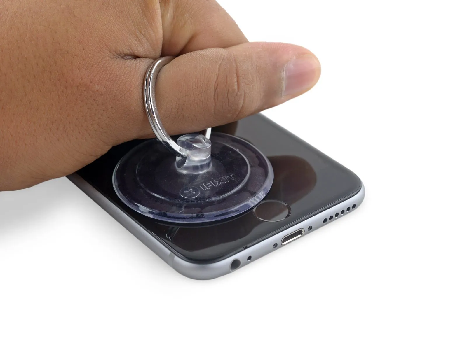
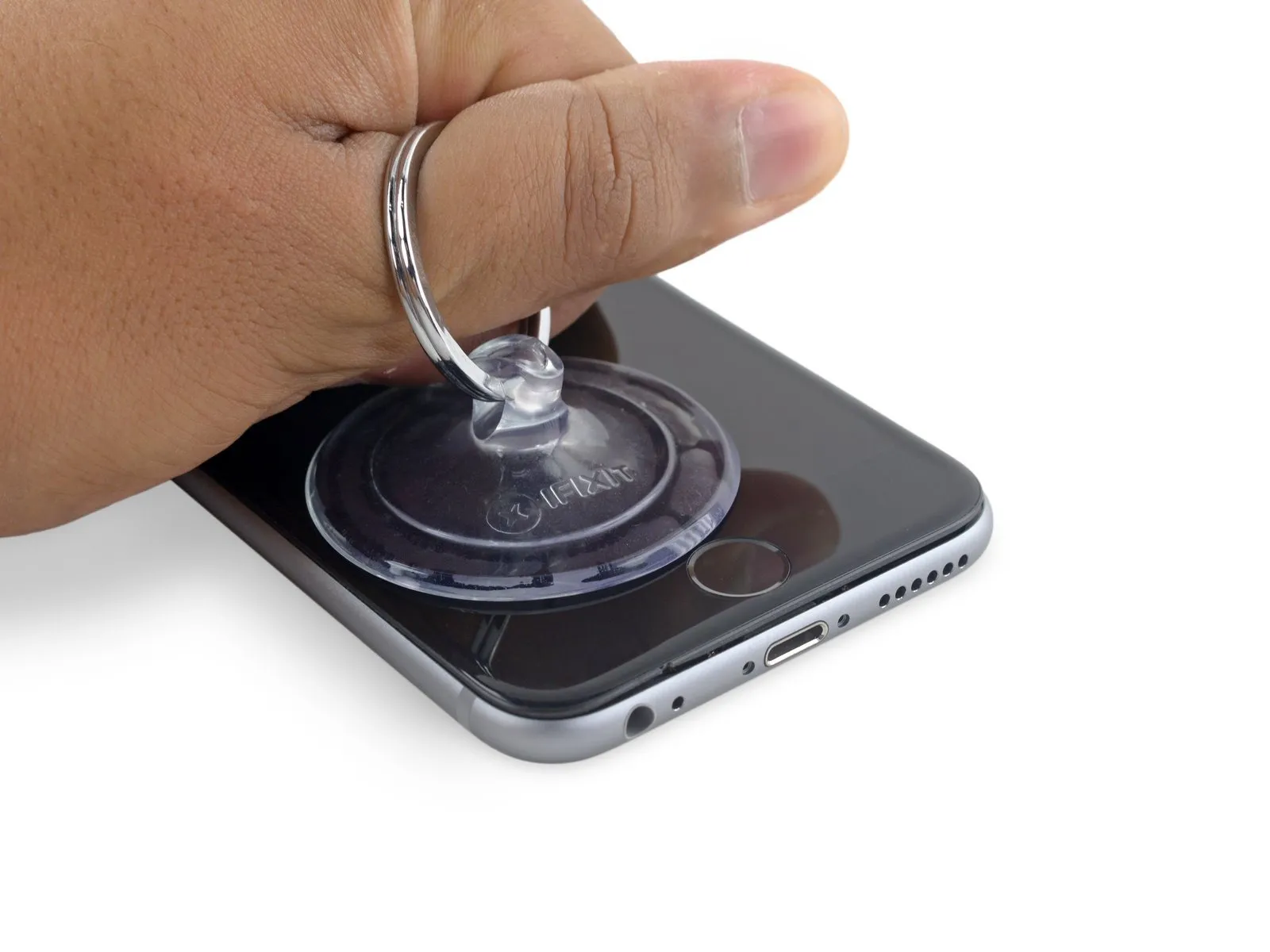
- Carefully use the suction cup to separate the display assembly, releasing any remaining adhesive bond.
- To prevent damage, limit the display's opening angle to a maximum of 90 degrees; the three cables connecting it to the top edge are susceptible to breakage if pulled taut.
Step 15
Step 16
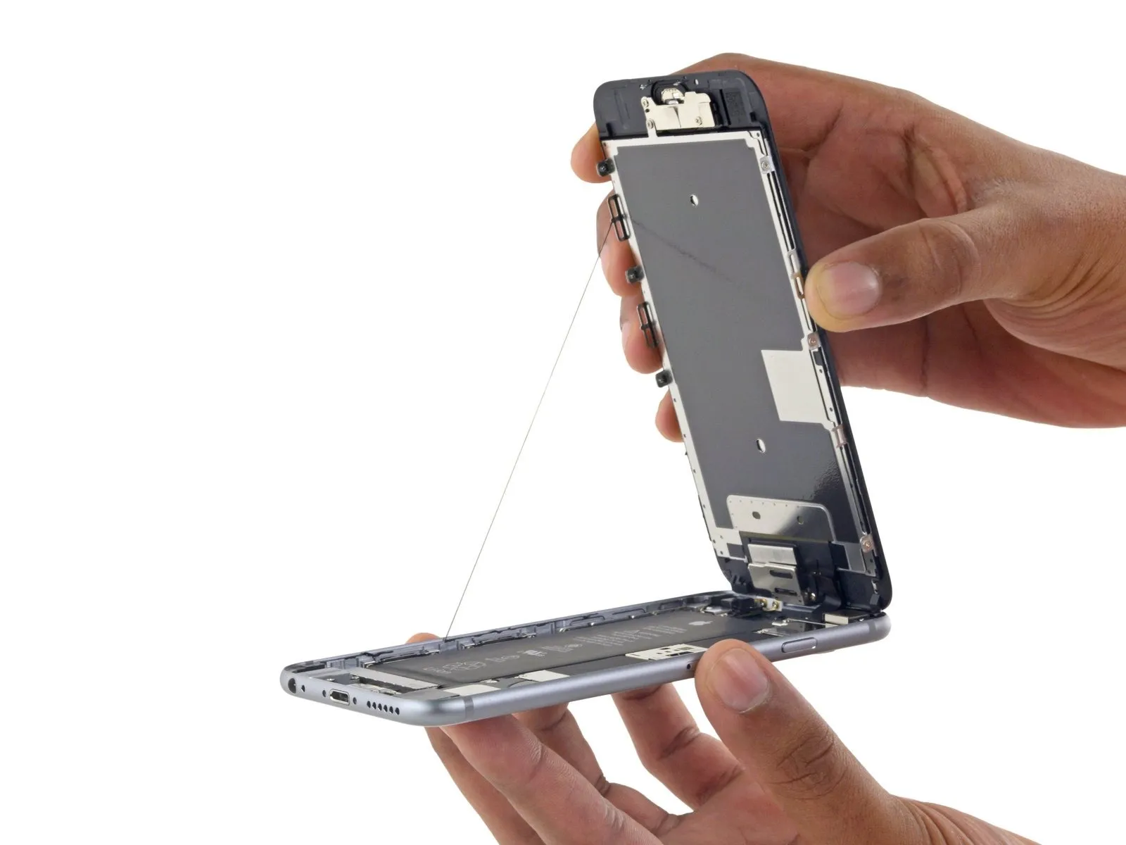
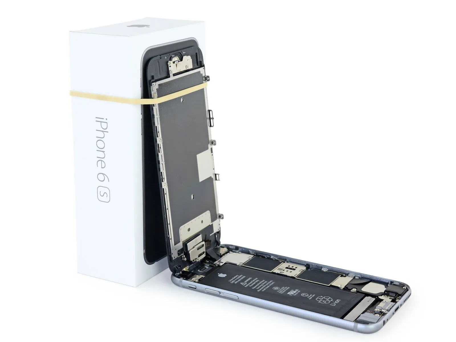
- Employing a careful touch, raise the display assembly by leveraging the front panel's upper clips, which function as a hinge to release the phone.
- Carefully position the display at a 90-degree angle, then secure it in an upright position using a support to allow for hands-free access during the repair process.
- To avoid stressing the display's wiring during the repair process, secure it with a rubber band.
- As a temporary measure, an unused, sealed can of soda can substitute for the display during the repair process.
- If you intend to substitute fresh adhesive along the display's perimeter during reassembly, stop at this point.
- To ensure proper alignment during reassembly, position the screen’s camera-side edge beneath the main body’s edge. The screen frame’s hooks must be situated under the main body’s rim, then gently pushed toward the camera end to facilitate cover closure and secure clipping.
- Ensure these clasps are positioned beneath the phone's outer edge, as they function as a securing mechanism rather than a traditional hinge; this placement allows the screen to smoothly and quietly return to its closed position, engaging with a gentle snap.
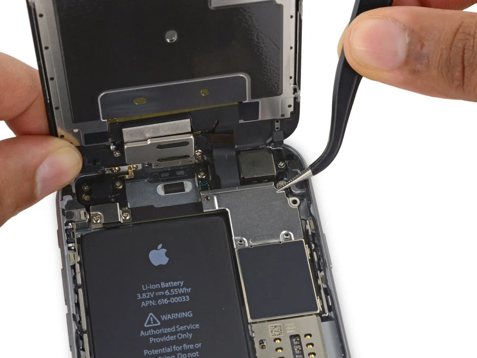
Step 17 | Battery Connector
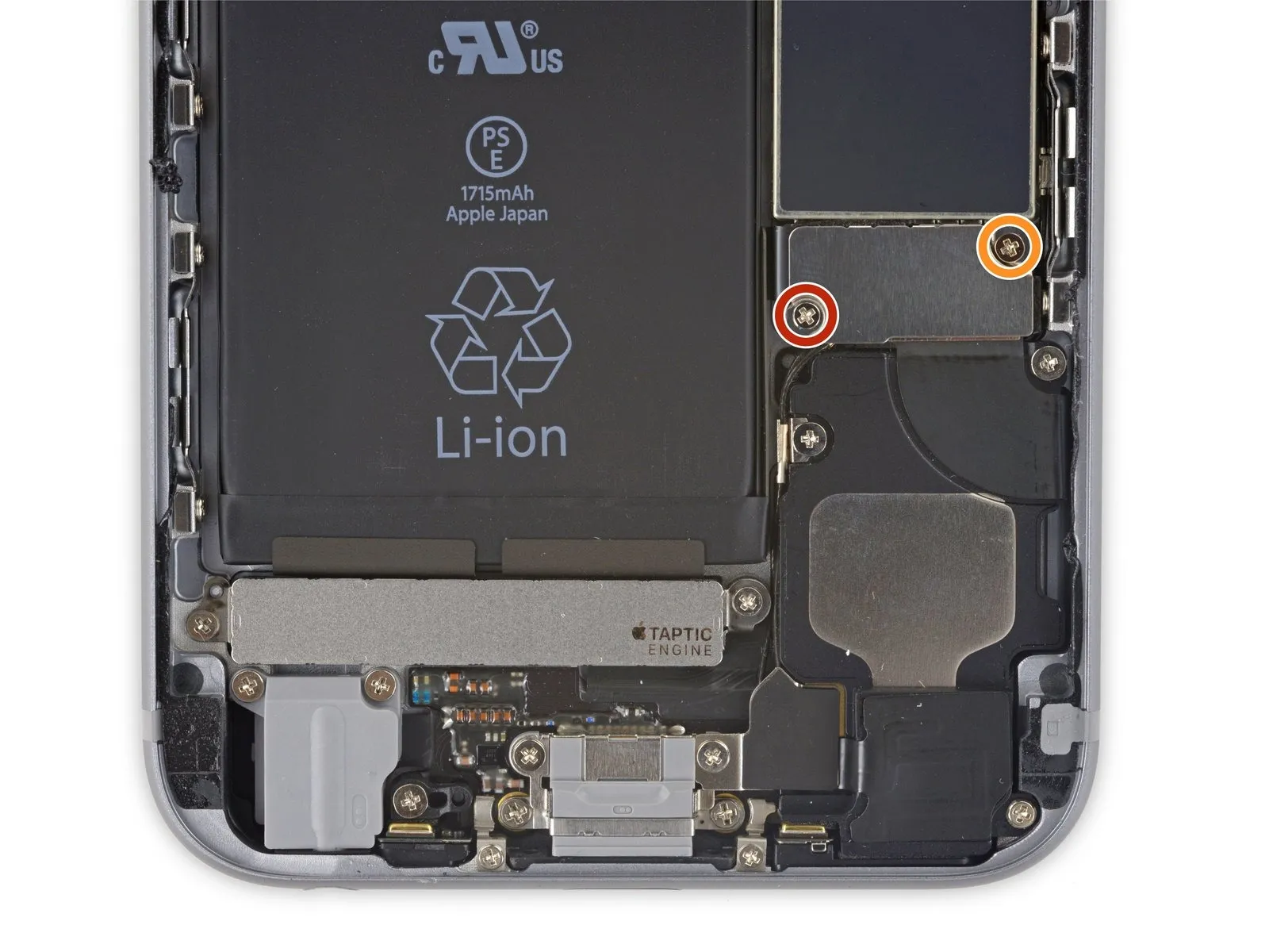
- Using a Phillips screwdriver, detach the battery connector bracket by unscrewing the two fasteners, each measuring the specified length.
- Begin the process by performing action one.The specified dimension is two point nine millimeters.Fasten with a screw.
- Begin the process with the number one.The specified dimension is two point two millimeters.Fasten with a screw.
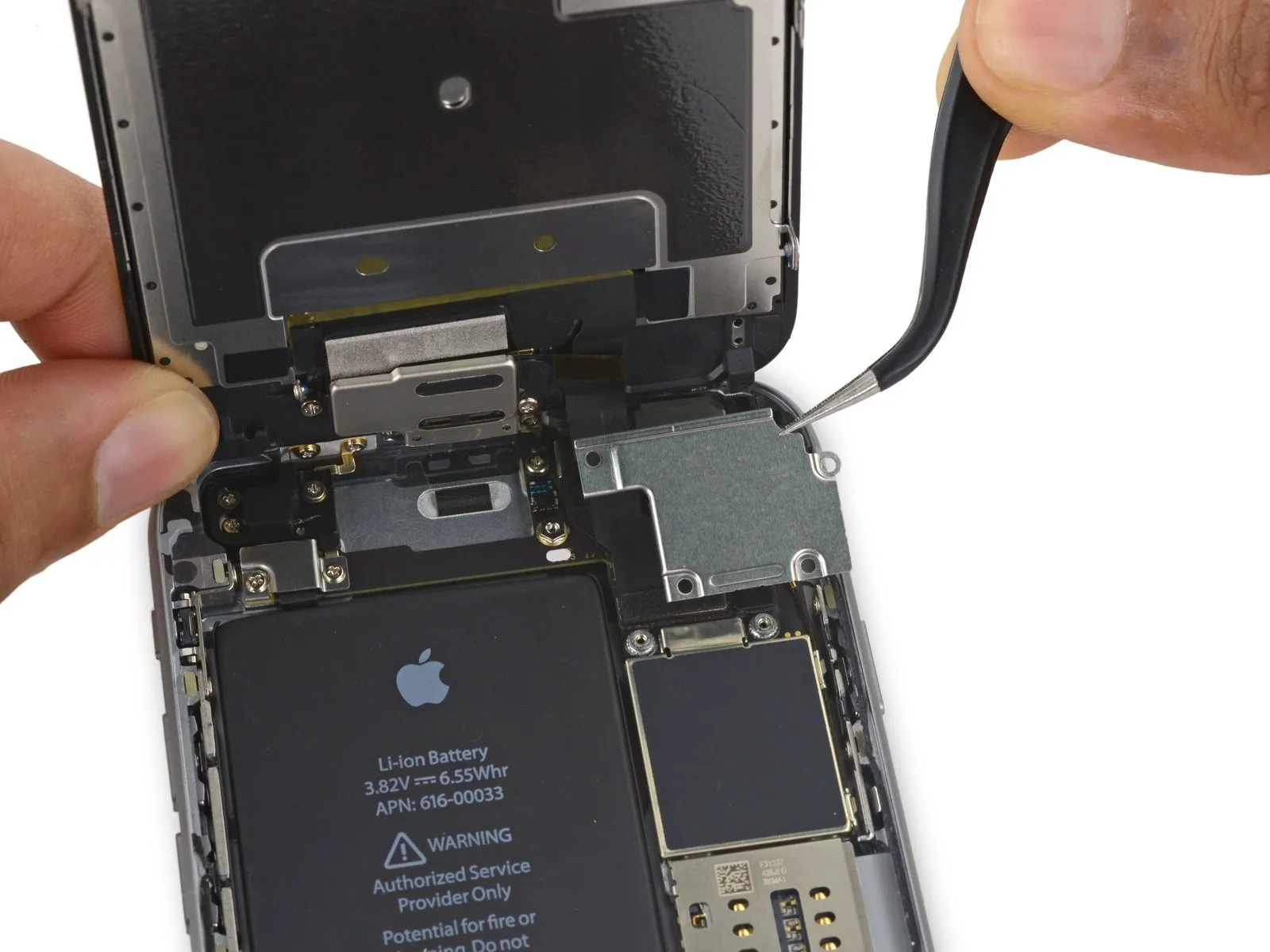
Step 18
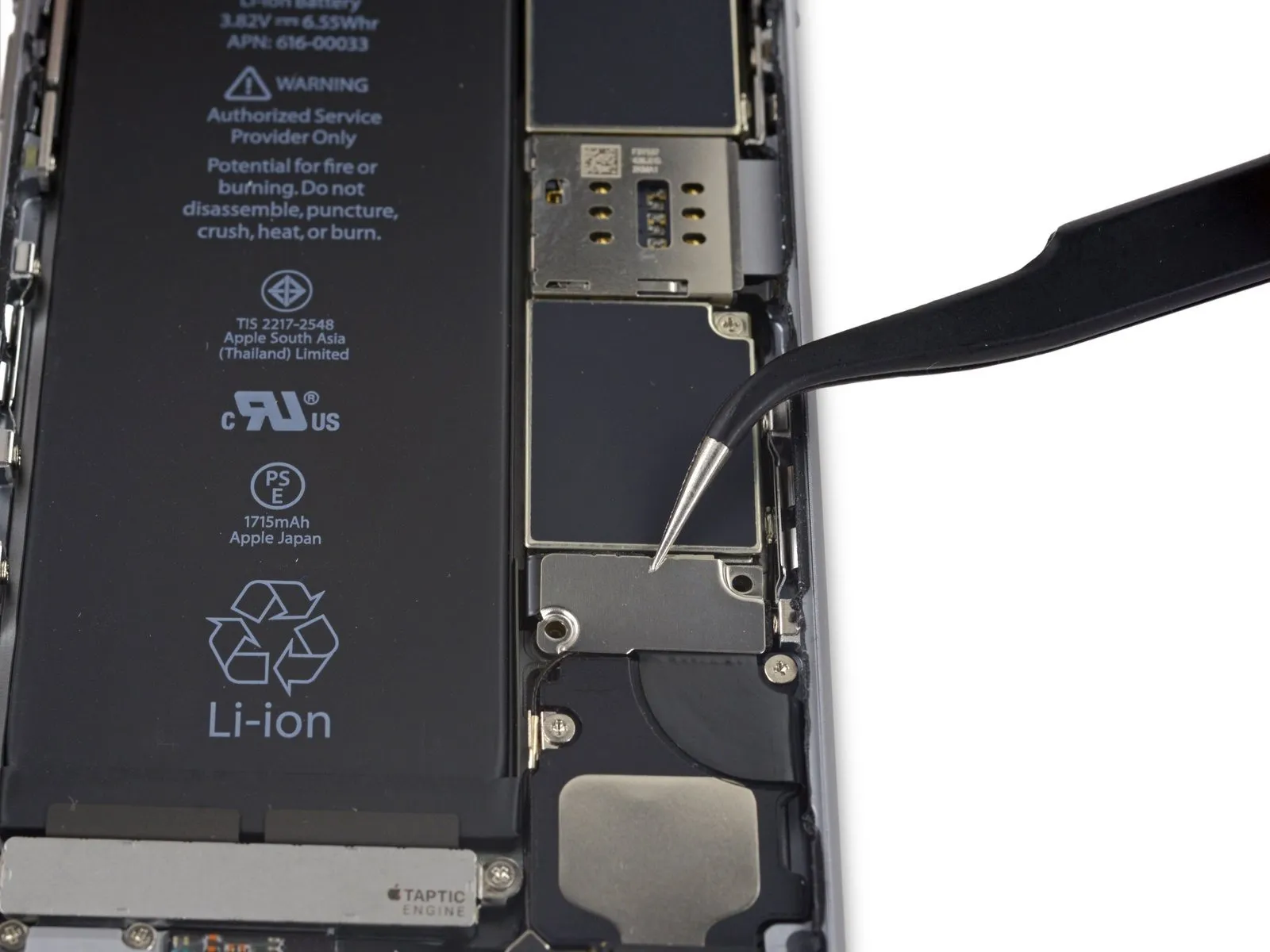
Using a T3 Torx screwdriver, detach the bracket securing the battery connector.
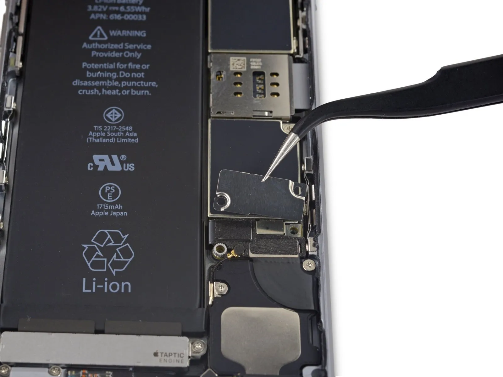
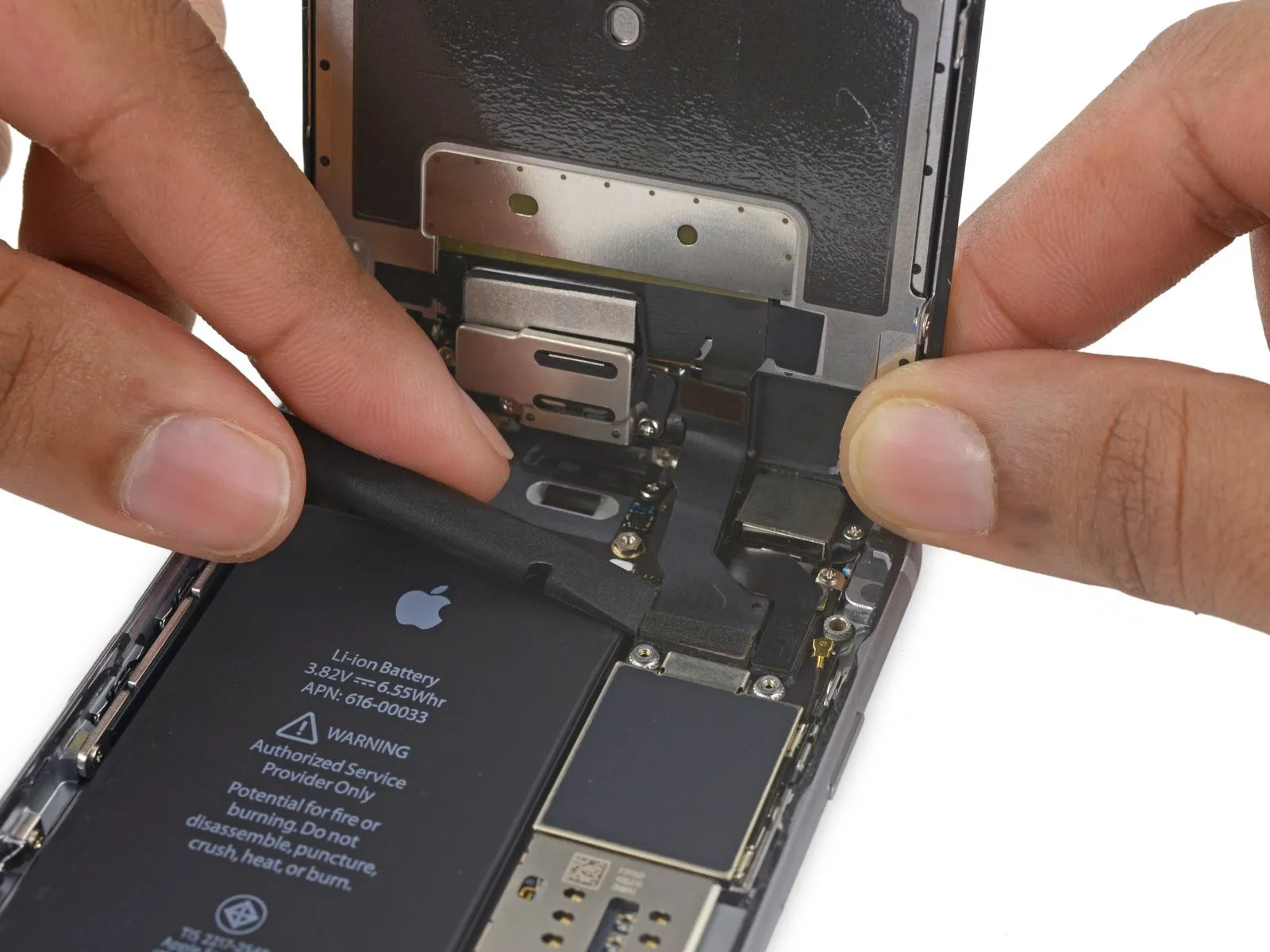
Step 19

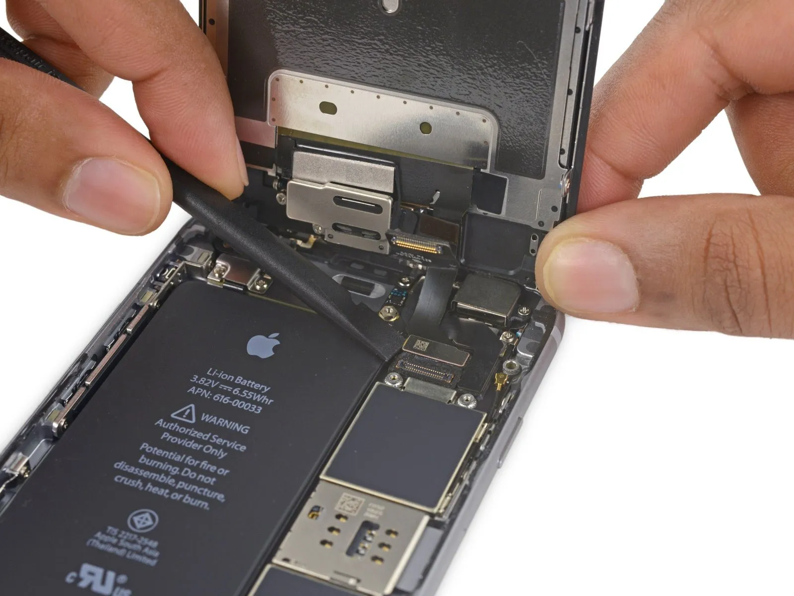
Carefully separate the battery connector from the logic board by inserting a spudger tip underneath it and applying upward force.
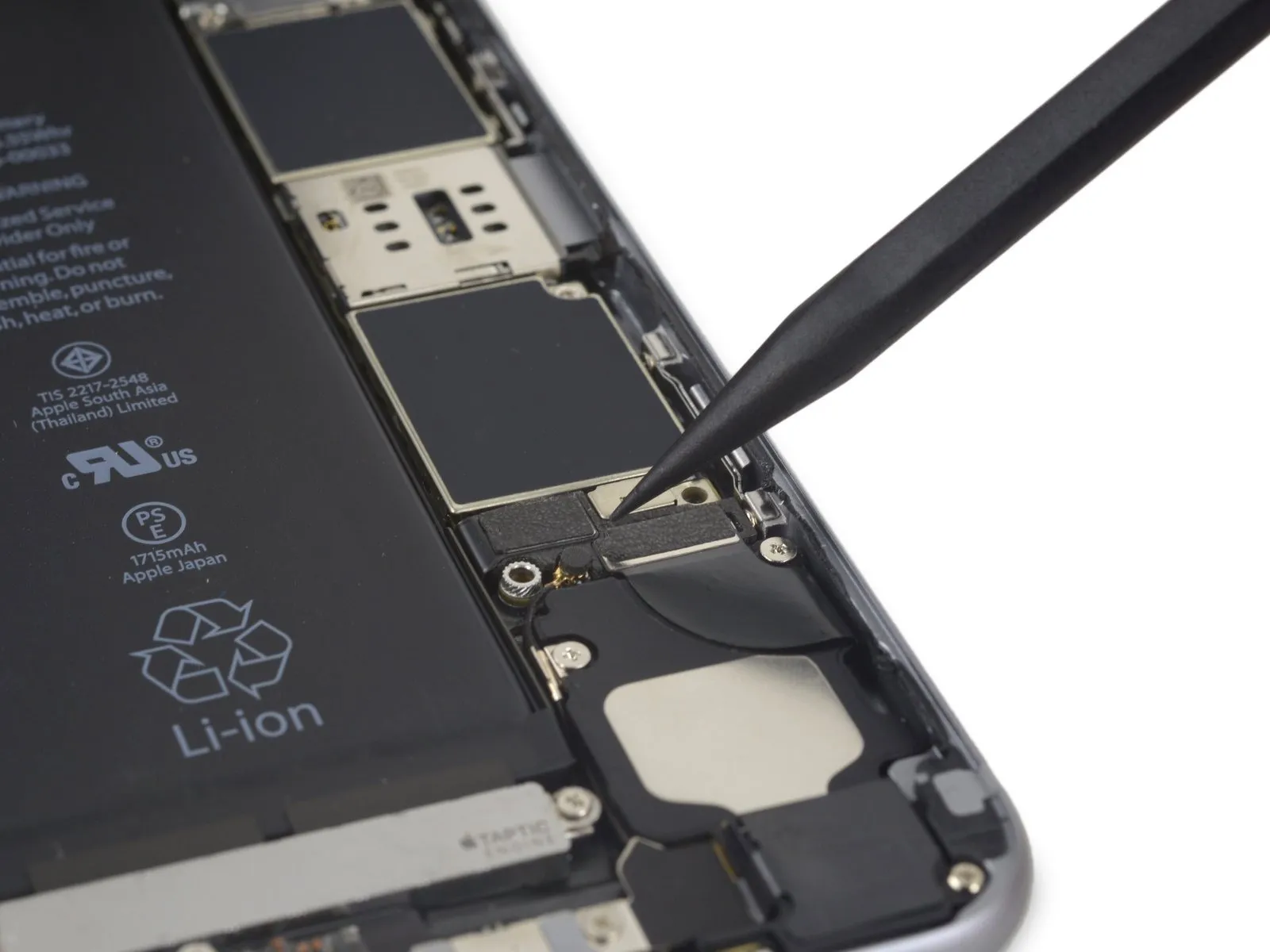
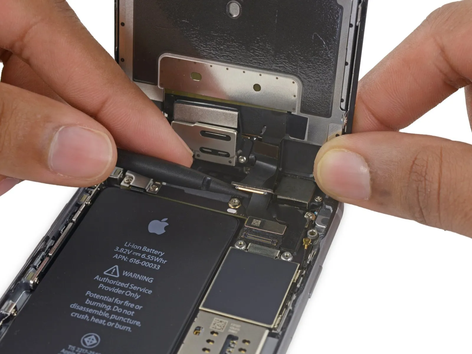
Step 20
To prevent unintended power-ups during the repair process, carefully disengage the battery connector from its corresponding socket on the logic board, ensuring it remains disconnected.
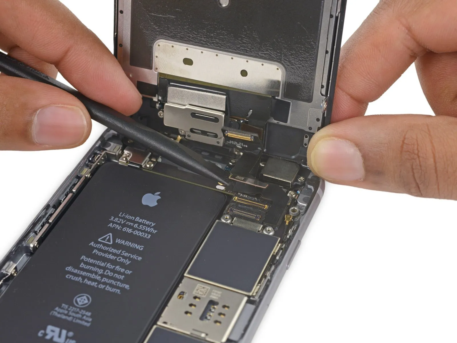
Step 21 | Unfasten the display cable bracket
- Detach the component.Use three screws, each measuring 1.2 millimeters.
- Detach the component.A screw with a 2.8 mm diameter is required.
Step 22
Step 23
Step 24
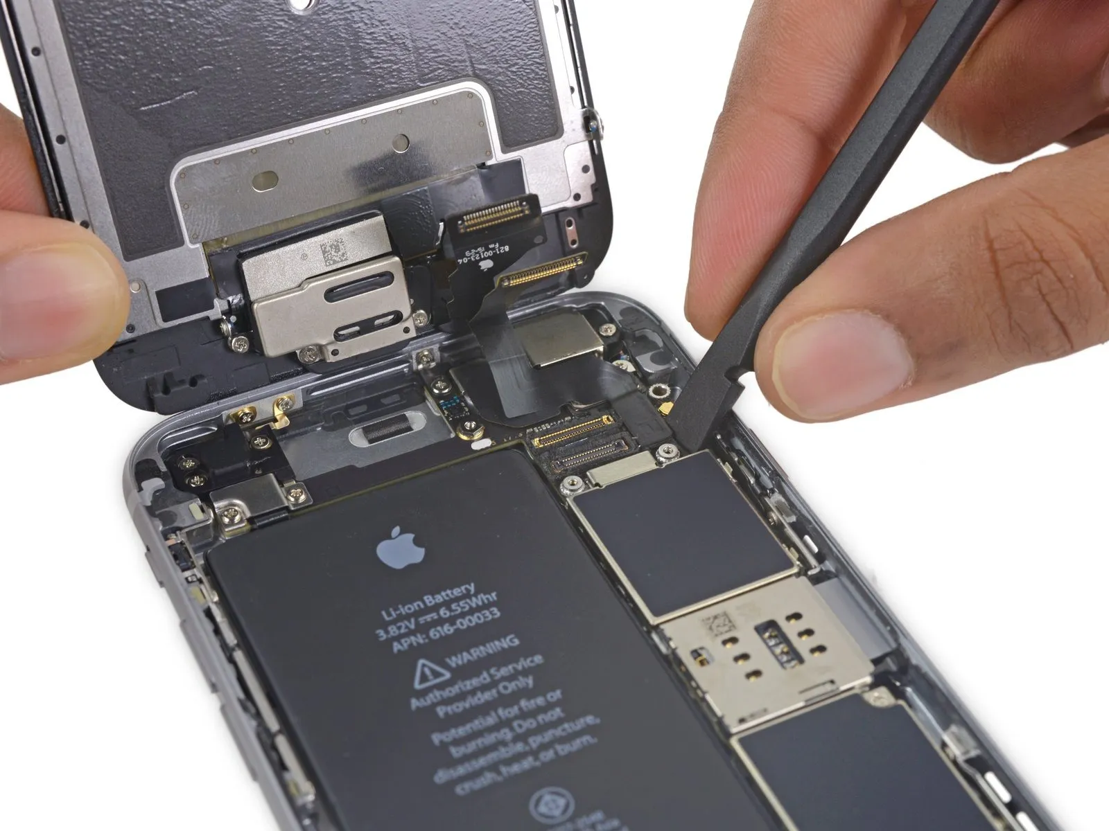
- Carefully release the digitizer cable from its connection on the logic board by applying upward pressure.
- To ensure proper seating of the digitizer cable, avoid applying pressure to the connector's central area; instead, gently press one terminal, followed by the opposite terminal.Applying pressure to the connector's central area risks component deformation and potential damage to the digitizer..
Step 25
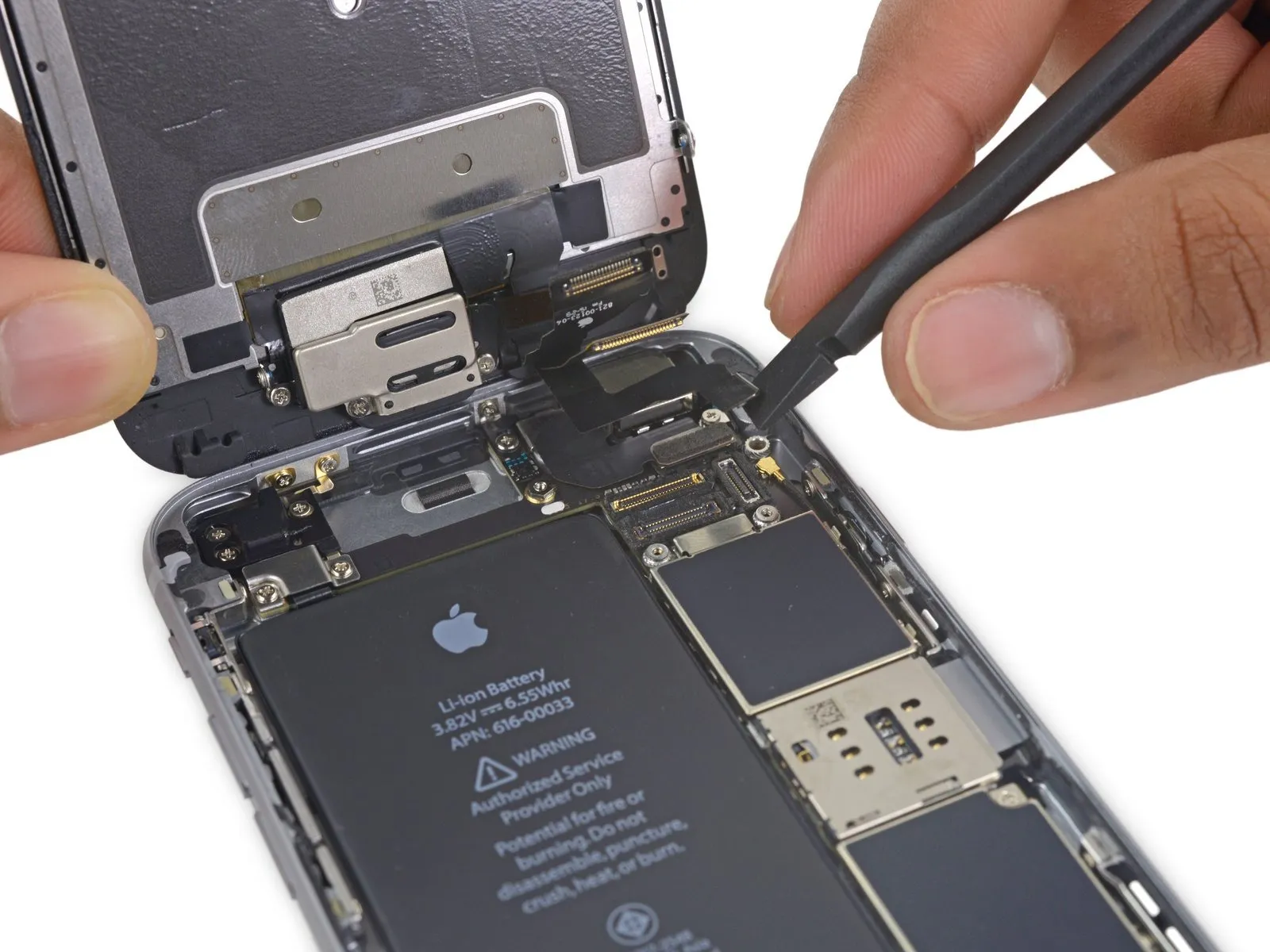
- Prior to either detaching or reattaching the cable in this procedure, ensure the battery is disconnected.
- Using a prying motion, carefully separate the display cable from its connector on the logic board.
Step 26
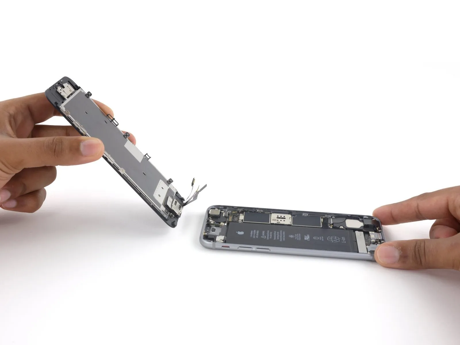
- Carefully detach the display assembly, ensuring no damage occurs.
- If you intend to substitute fresh adhesive along the display's perimeter during reassembly, stop at this point.
Step 27 | Speaker


- Carefully insert the tip of a screwdriver to.Use a spudger.Carefully raise and detach the antenna cable from the logic board's lower termination.
- Gently position the connector onto the socket, ensuring proper alignment, and subsequently secure it with the flat end of a screwdriver.Use a plastic pry tool, often referred to as a spudger.Ensure the component seats properly by applying pressure until a distinct click confirms secure engagement; if this doesn't occur, verify its positioning and avoid applying undue force.
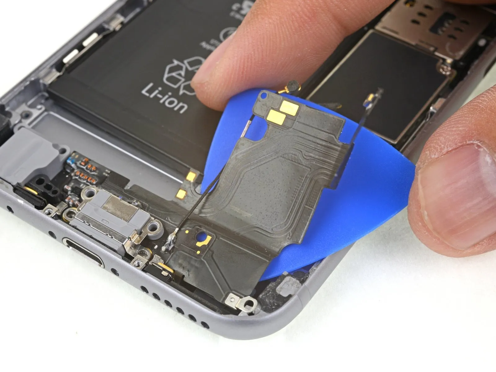
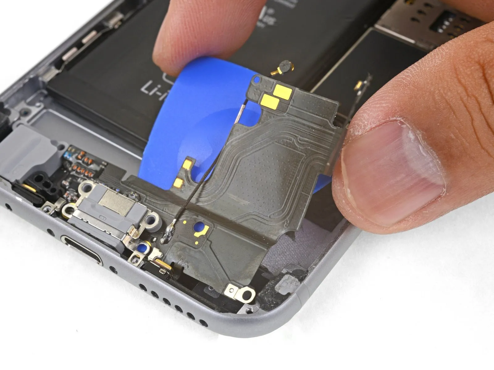
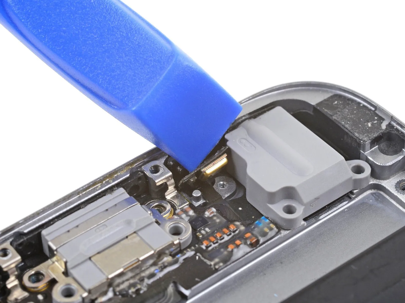
Step 28


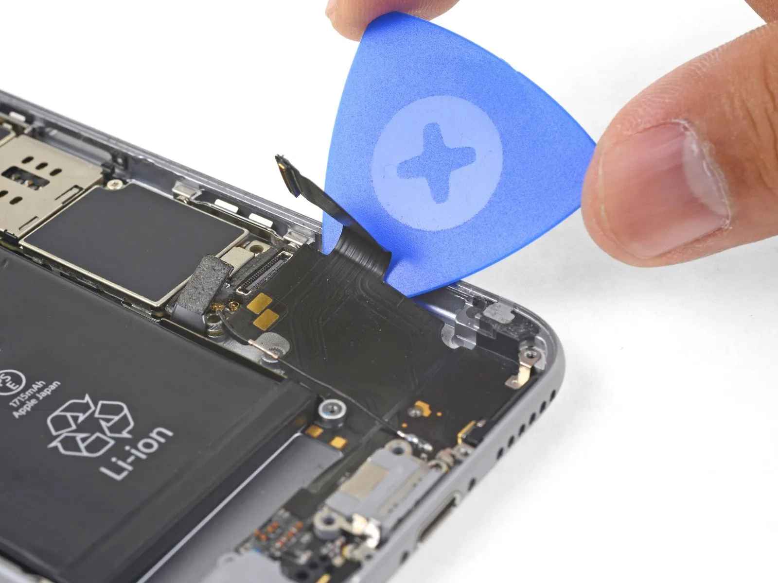
- Carefully insert the tip of a screwdriver to.Use a plastic pry tool, often referred to as a spudger.Carefully raise the Lightning connector ribbon cable and detach it from the corresponding socket located on the logic board.
Step 29
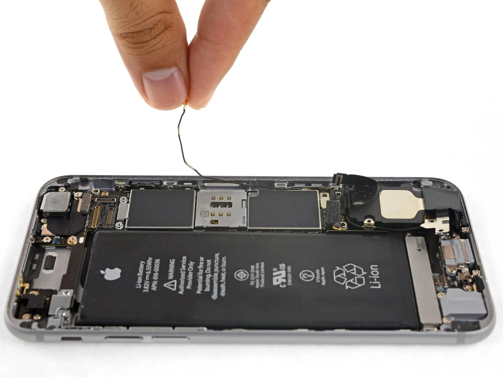
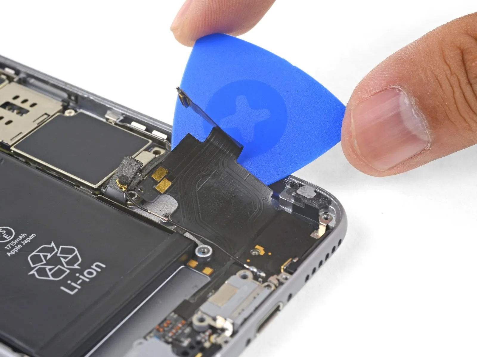
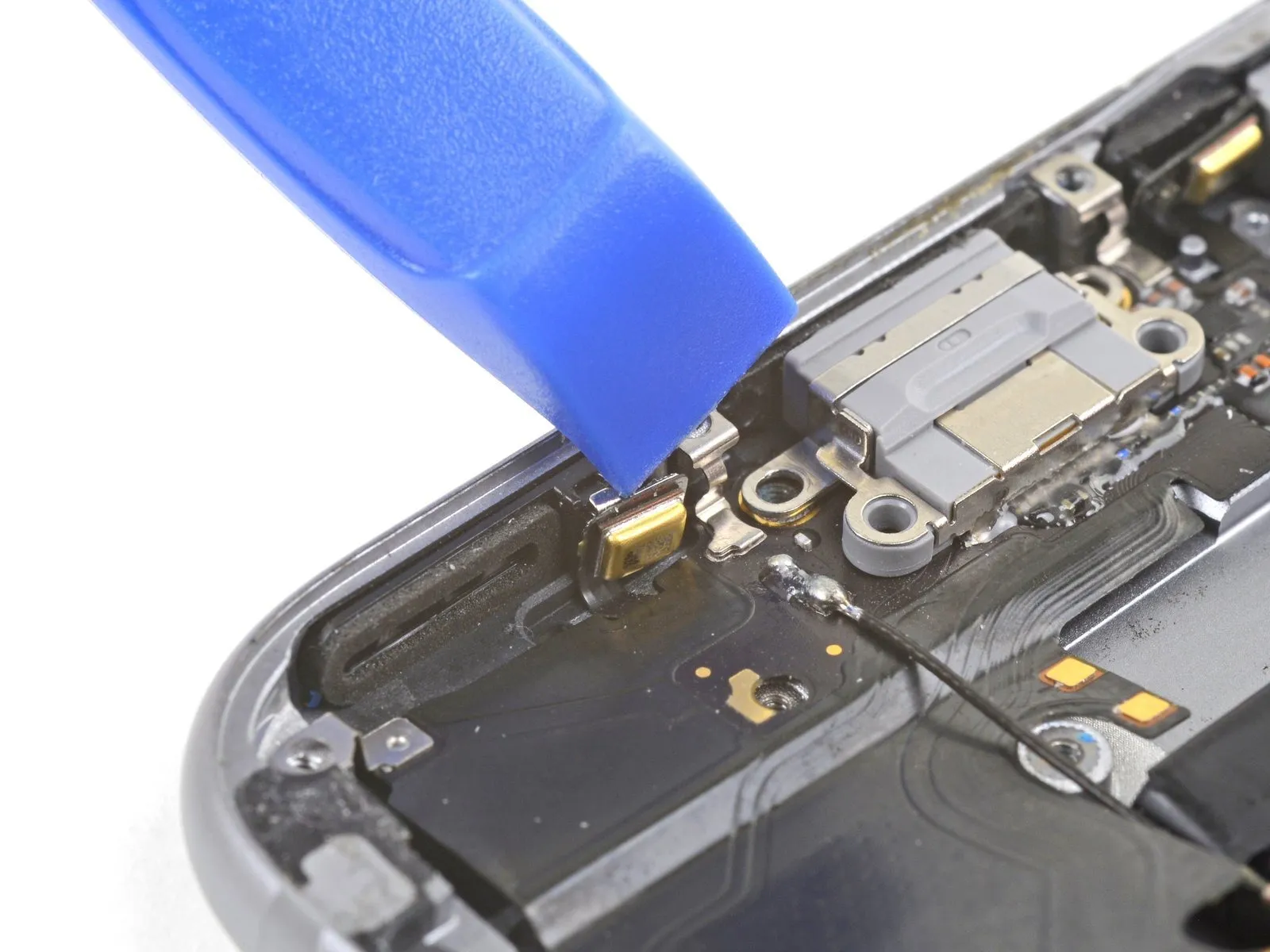
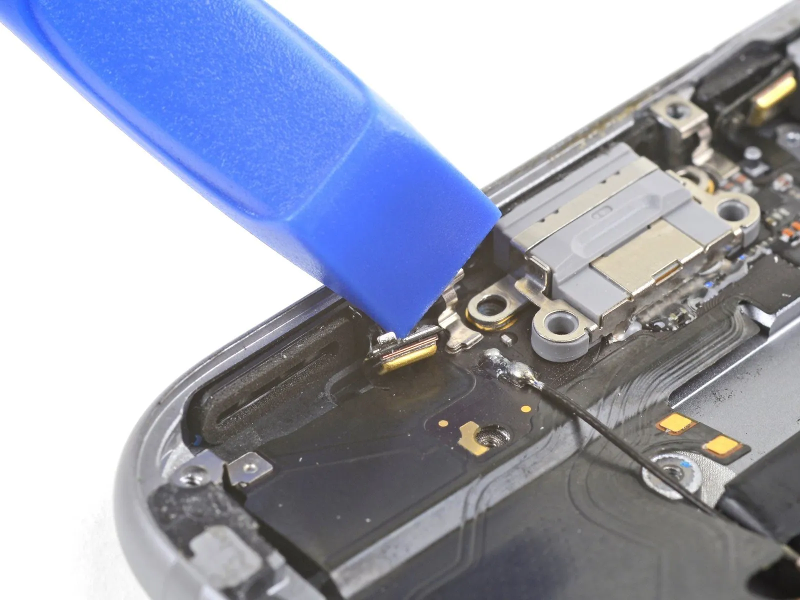
During Lightning connector replacement, the antenna cable can remain attached, allowing you to bypass these two procedures.Exercise extreme caution to prevent damage to the antenna cable, as it is fragile.As the loudspeaker's position changes.
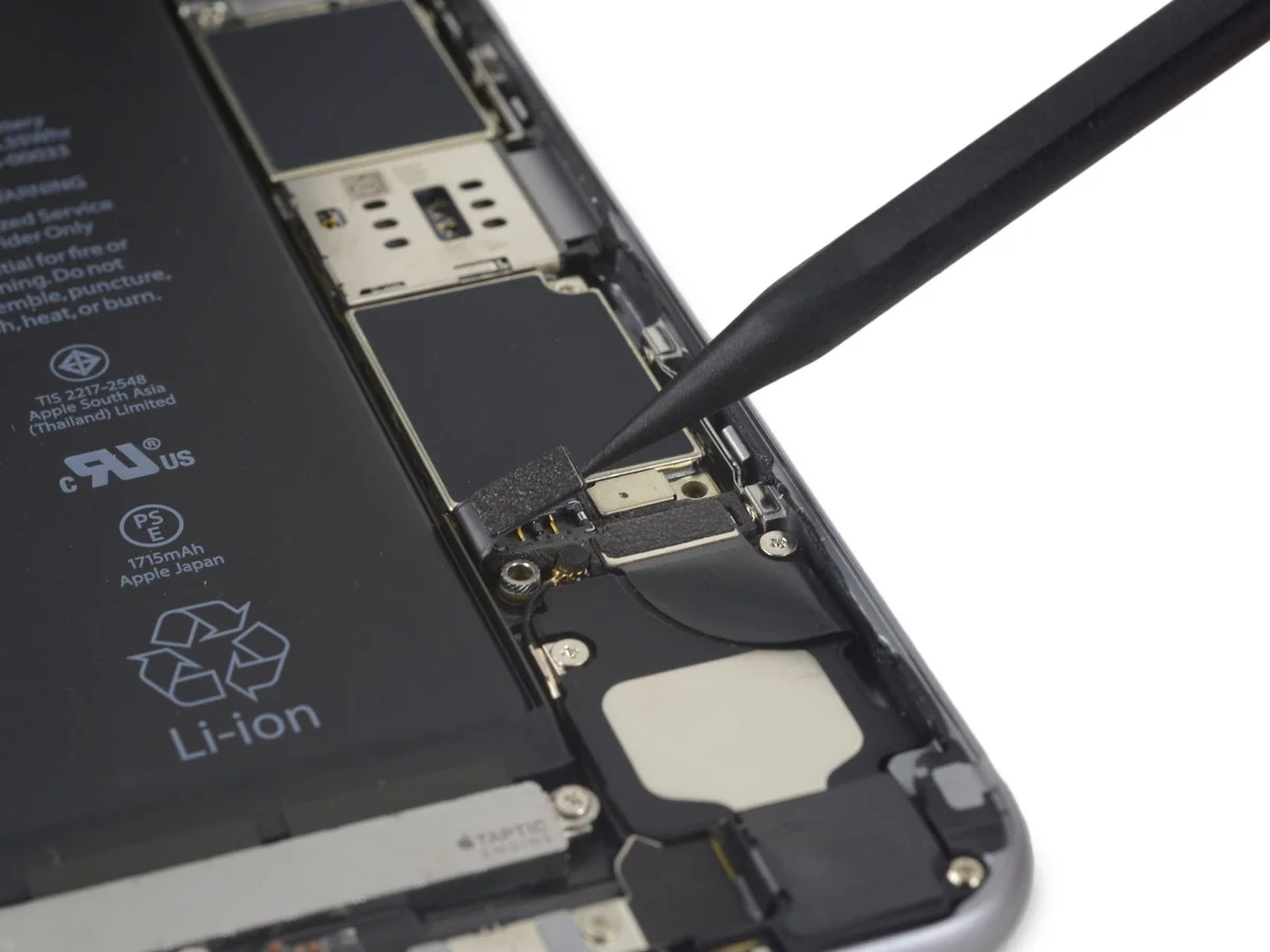
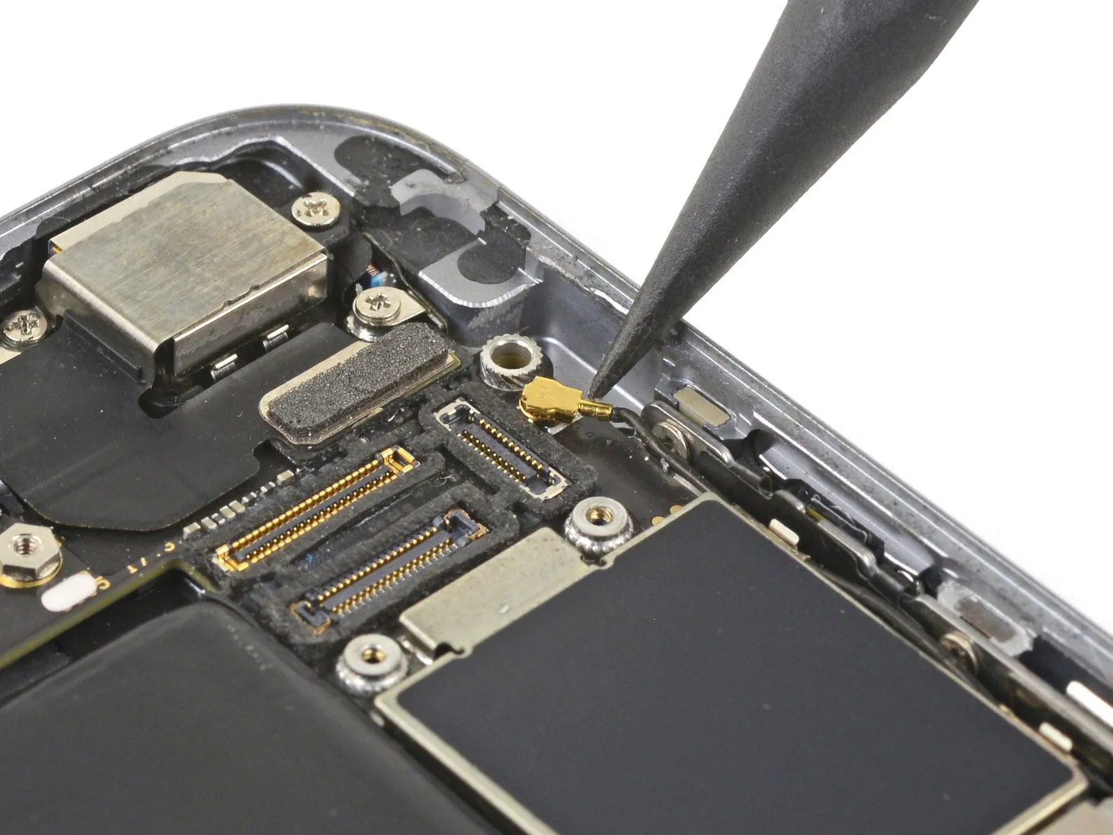
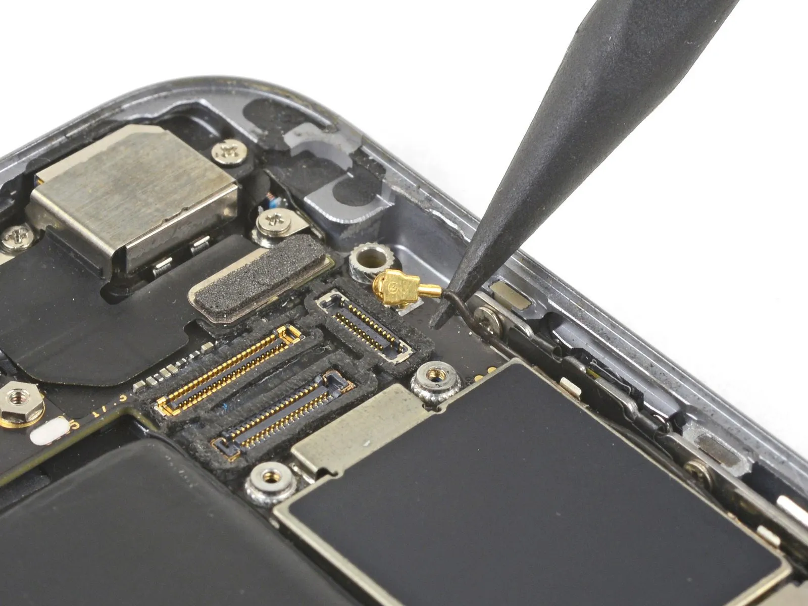
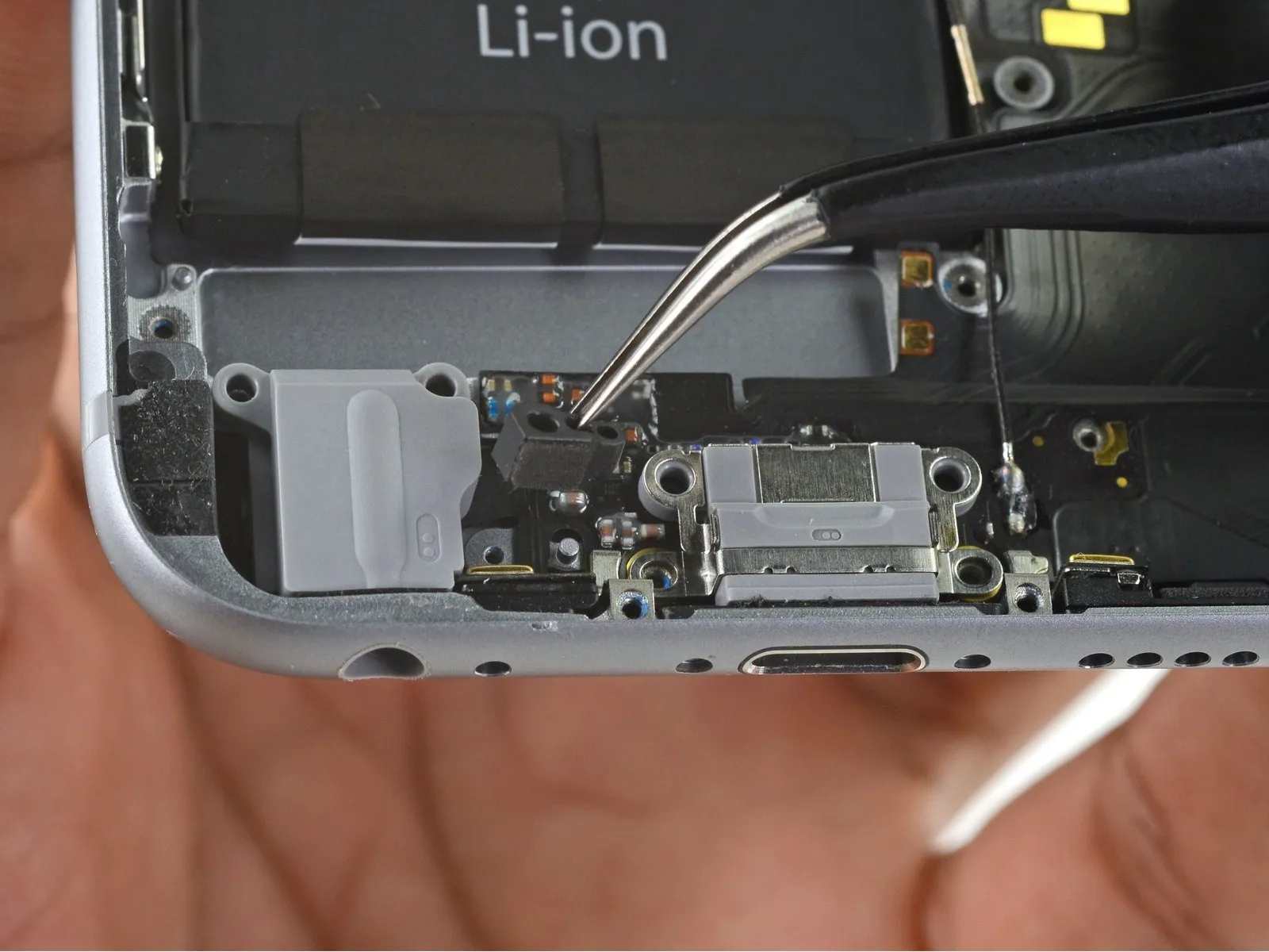
- Carefully employ a spudger tip to separate the antenna cable from its connector located on the logic board, positioned close to the top edge.
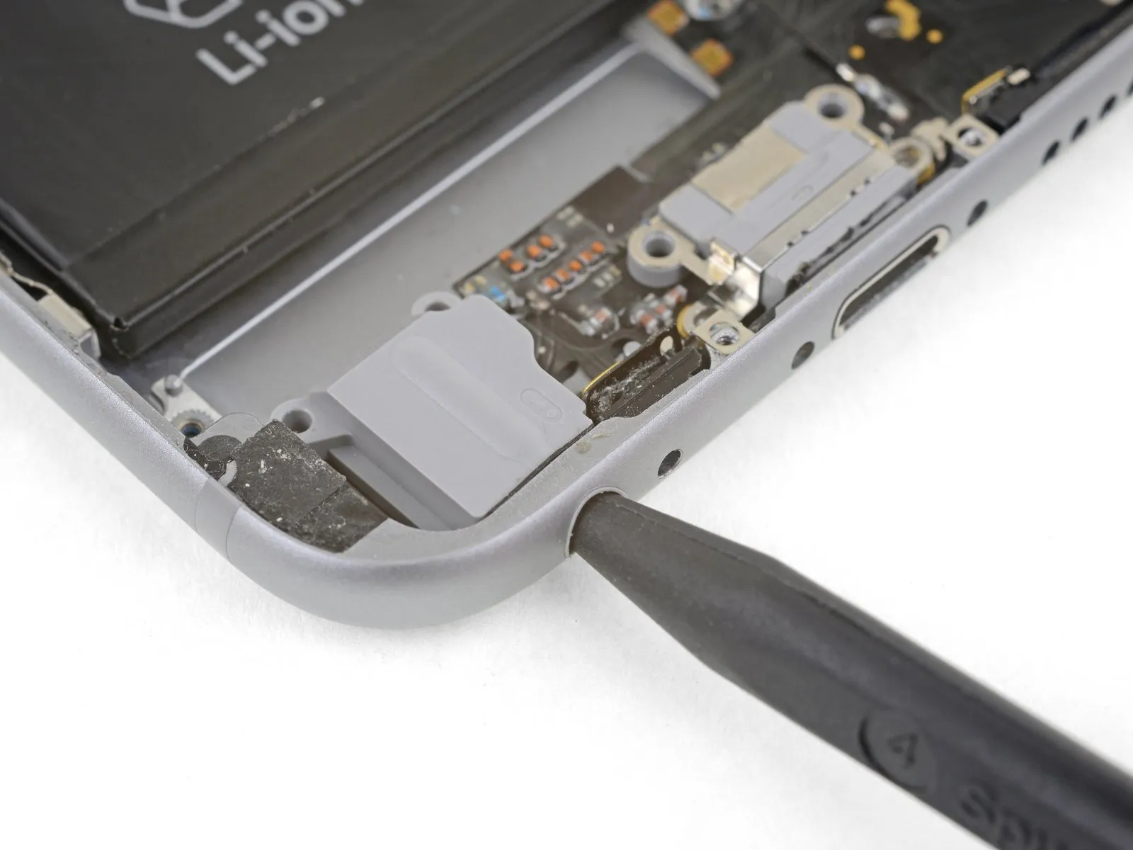
Step 30
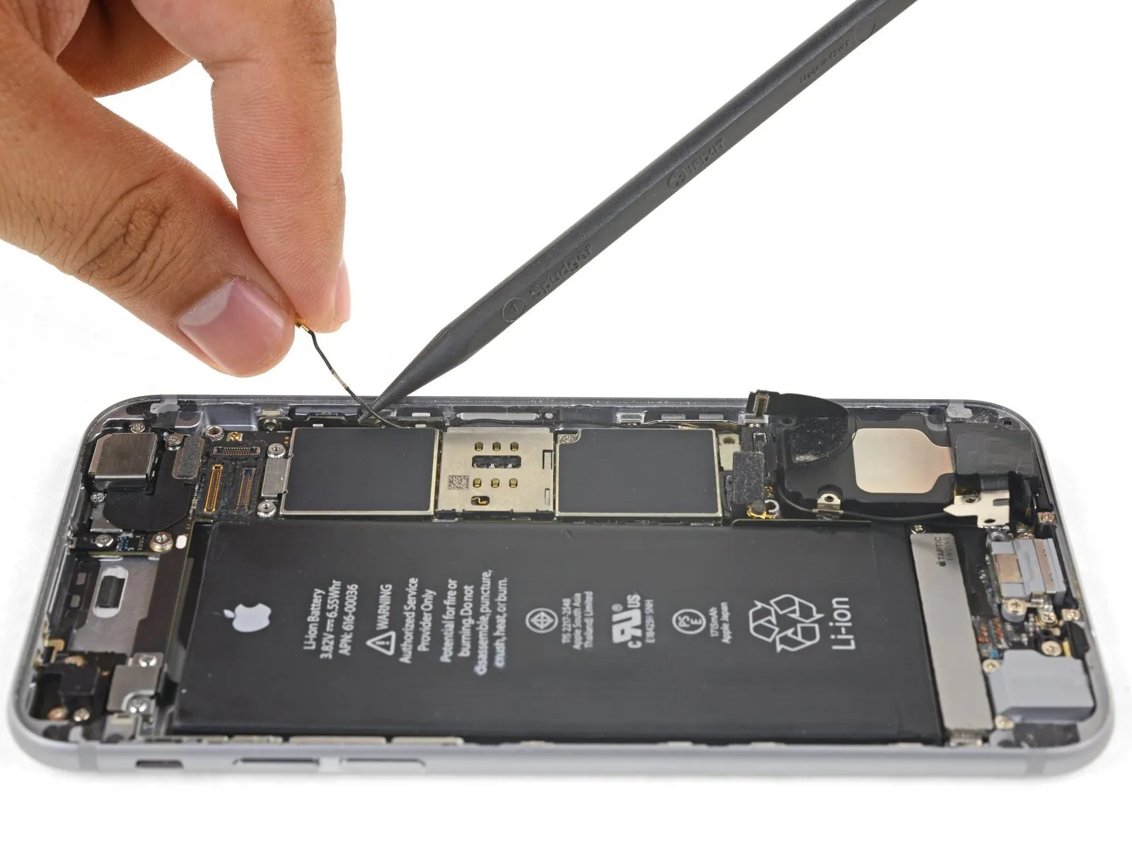
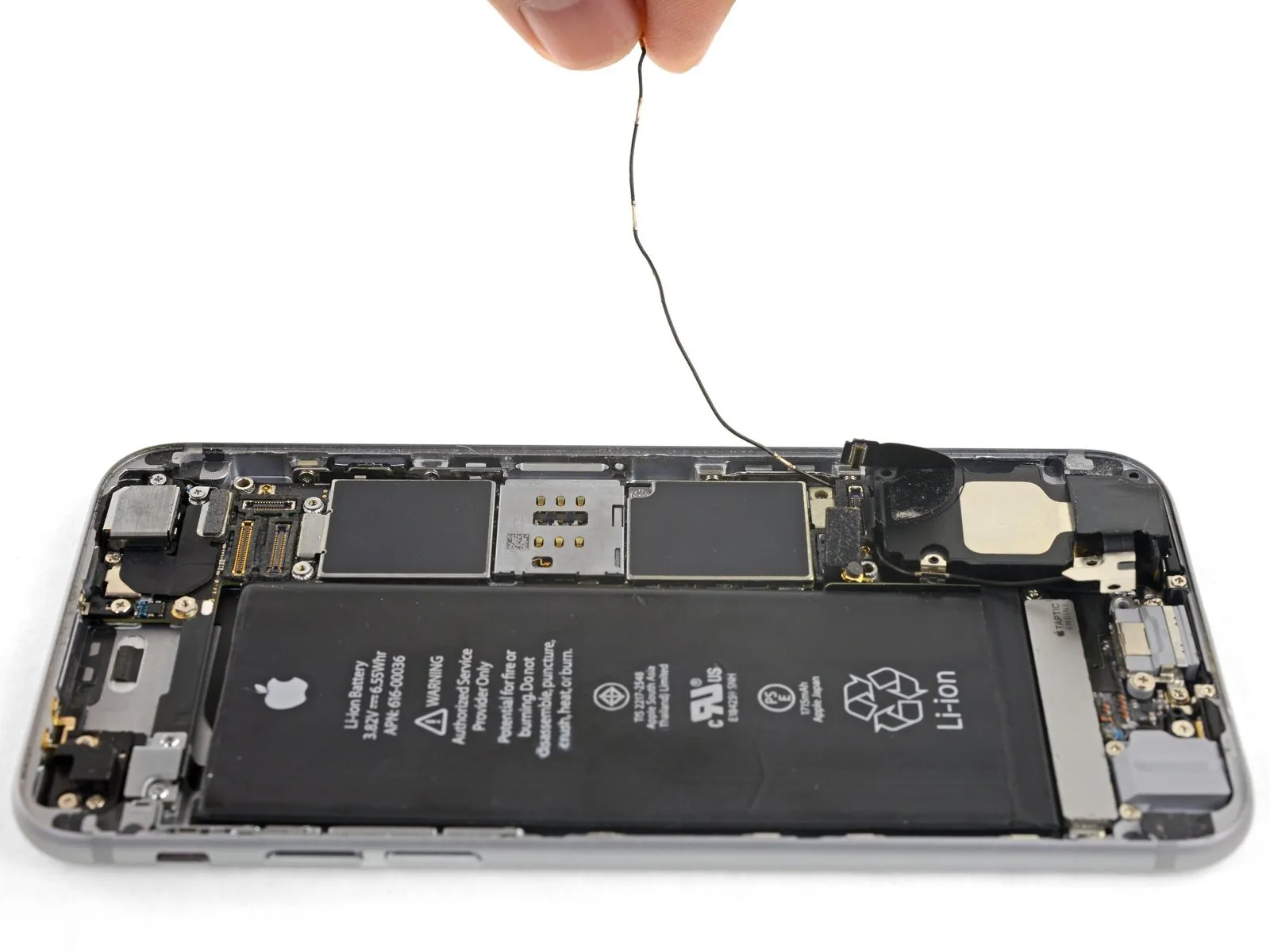
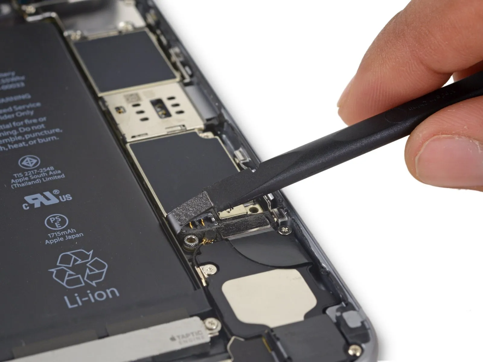
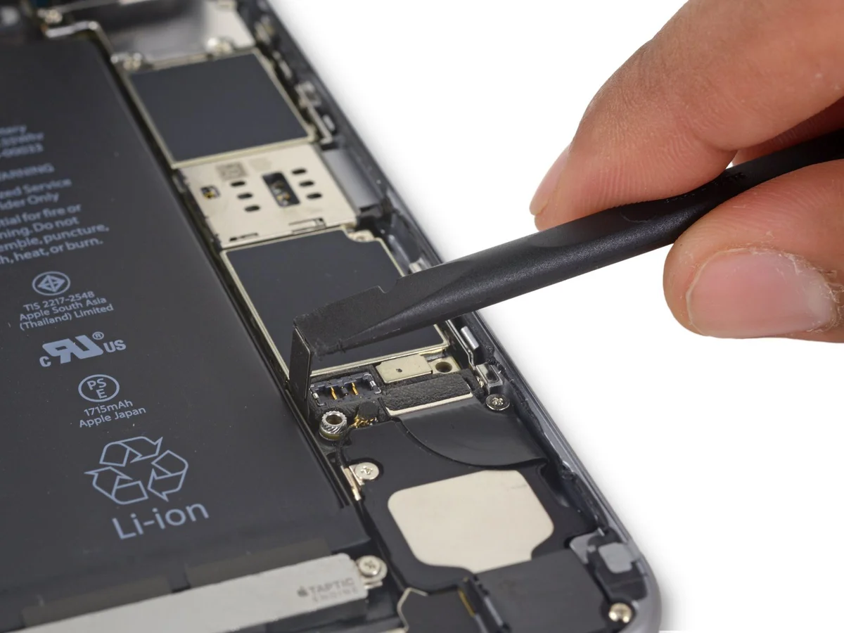
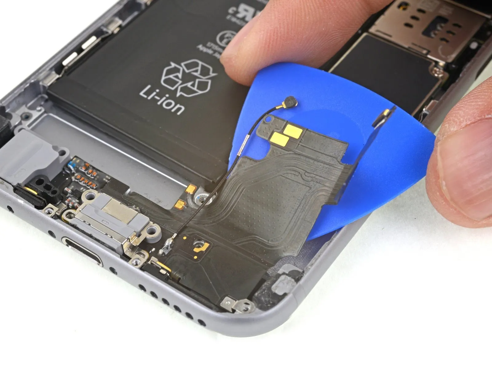
To release the antenna cable, gently detach it from the phone's side edge, utilizing a spudger tip to disengage it from the securing clips.
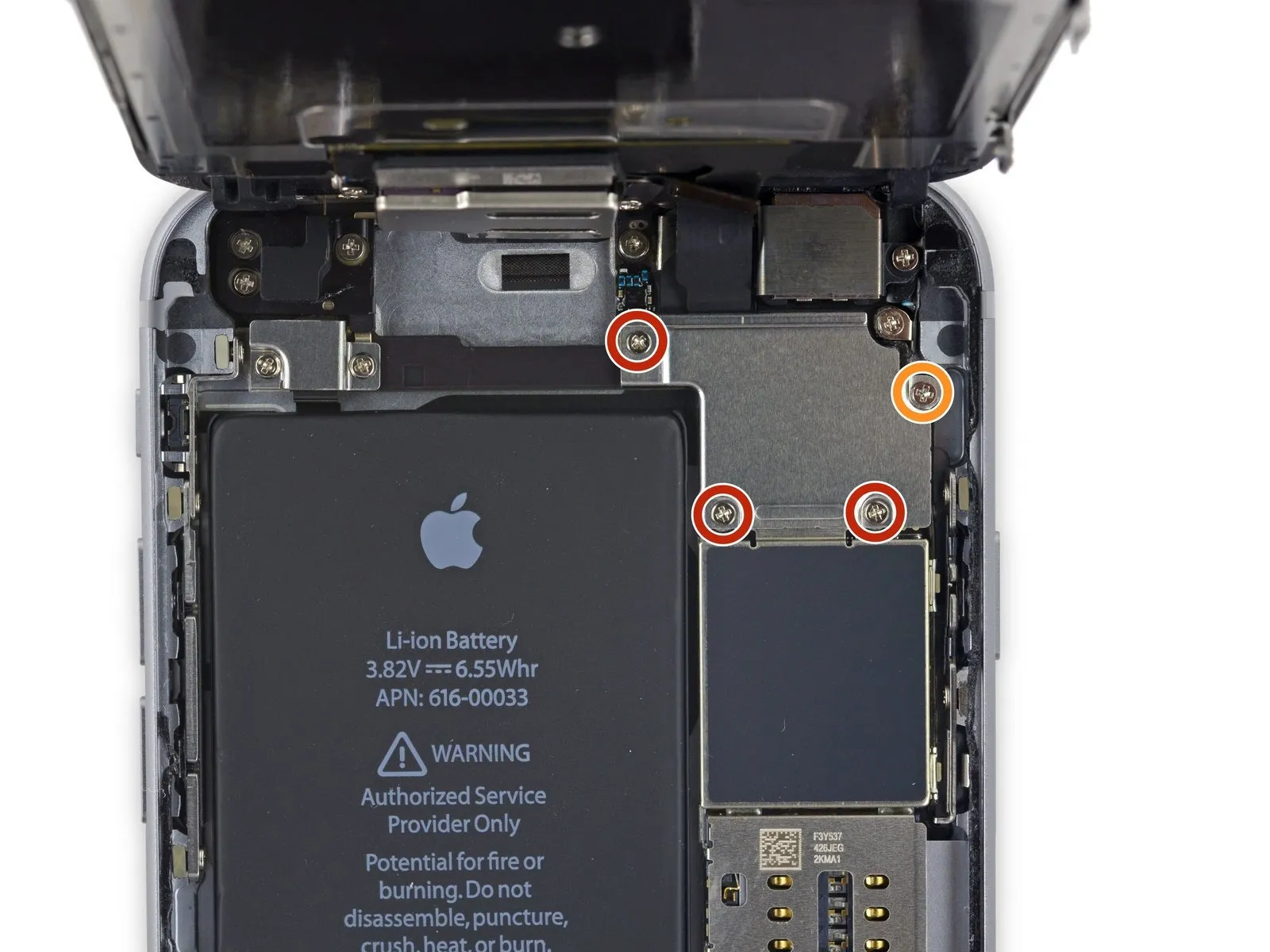
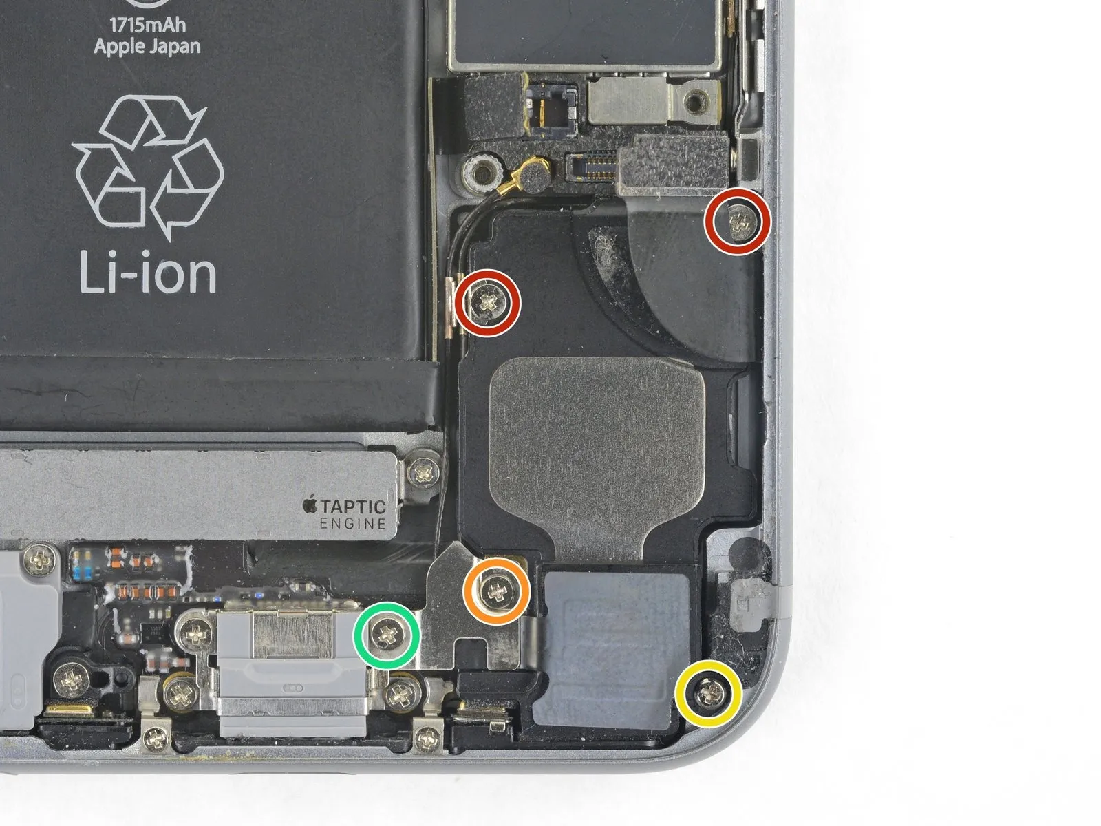
- To ensure adequate clearance for cable routing, slightly reduce the tightness of this.Employ a Phillips head screwdriver.To allow for easier manipulation during subsequent steps, ensure the logic board is firmly fixed in place.
- Ensure this screw is securely tightened again when reassembling the component.
Ensure the antenna cable is positioned below the logic board's corner during reassembly.
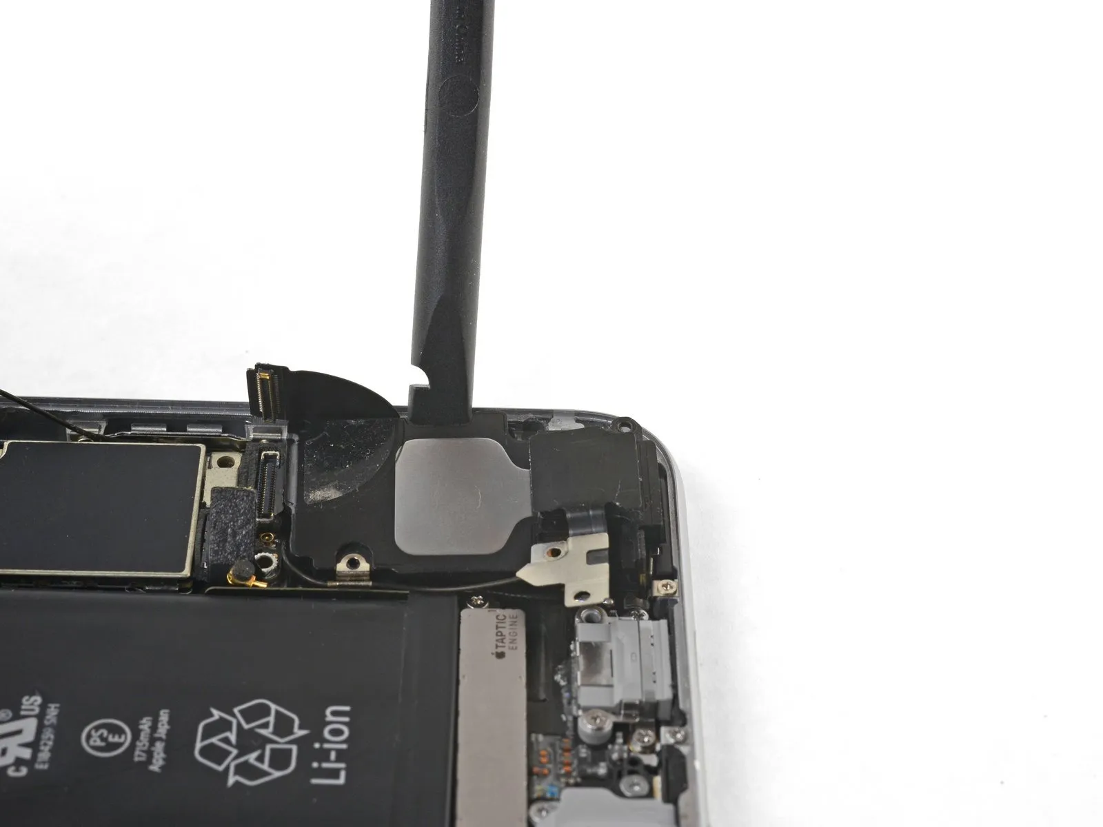
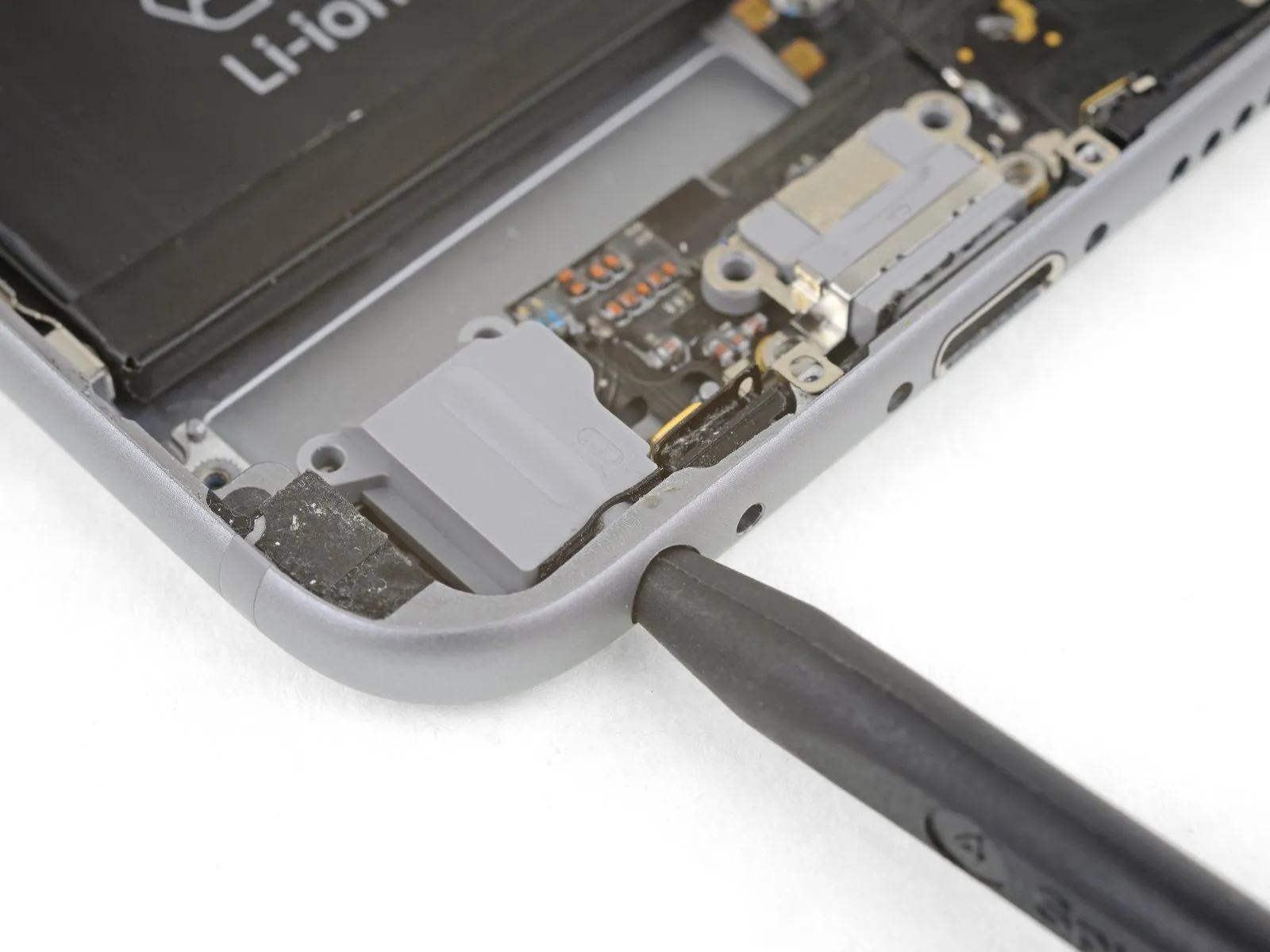
Following antenna cable rerouting, the SIM card tray can be reinstalled.
Should you encounter any difficulty during movement, immediately cease and verify the antenna cable isn't being obstructed by the tray.
Step 31
- Take out these components.Use a Phillips head screwdriver.Using the provided M4x12 screws, fasten the speaker to the rear case, ensuring proper alignment.
Two.Use fasteners with a diameter of 2.6 millimeters.
Begin the process with the number one.Use a screw with a diameter of 2.3 millimeters.Carefully check for tape covering this screw.
Begin the process by executing step one.Use a 2.3-millimeter screw.Distinguish this screw from the previously encountered one to prevent misidentification and incorrect assembly.
Begin the process by executing step one.Use a 3.0 mm screw.
Step 32
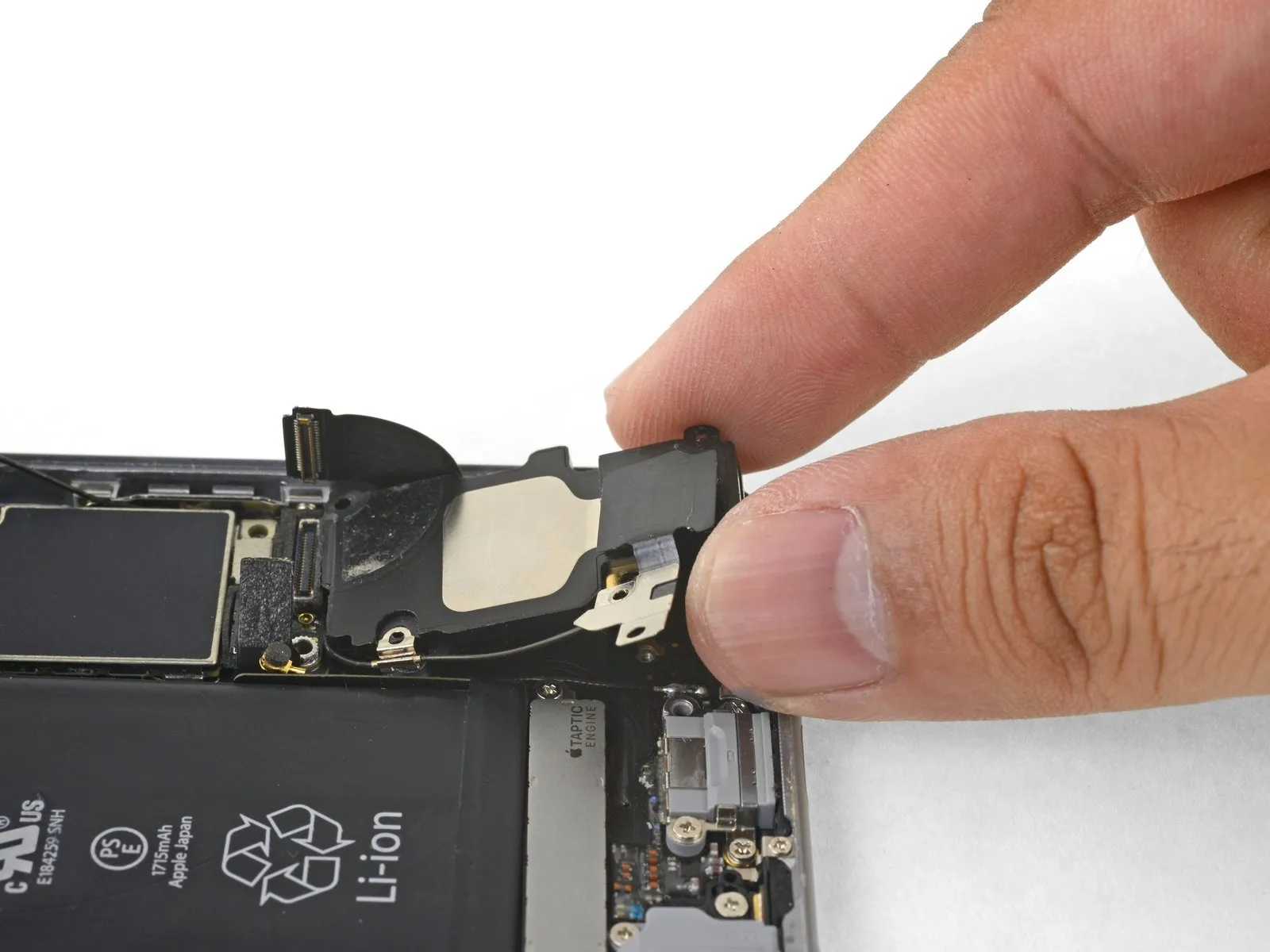
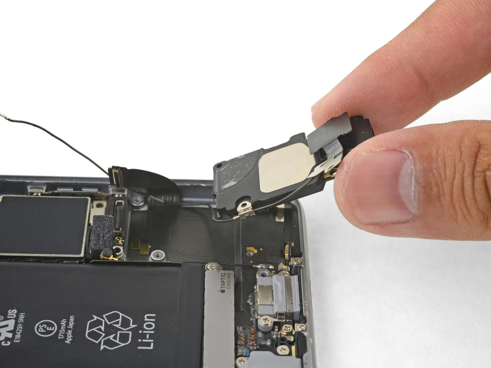
- Using a spudger with a flat tip, carefully slide it into the gap located along the speaker module's side, where it meets the device casing.
- Carefully apply separating force to release the speaker module.
Carefully raise the speaker module, now detached, from within the device to fully extract it.
Step 33 | Lightning Connector Assembly
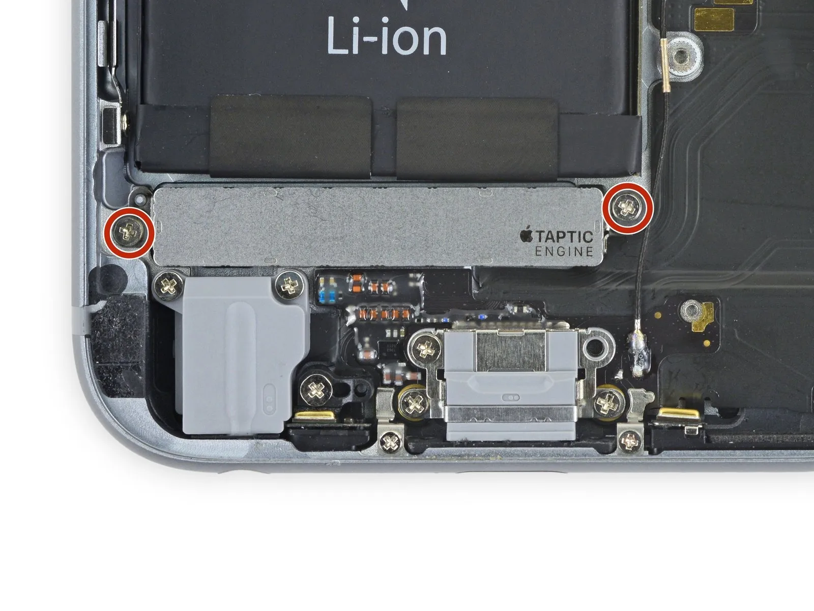
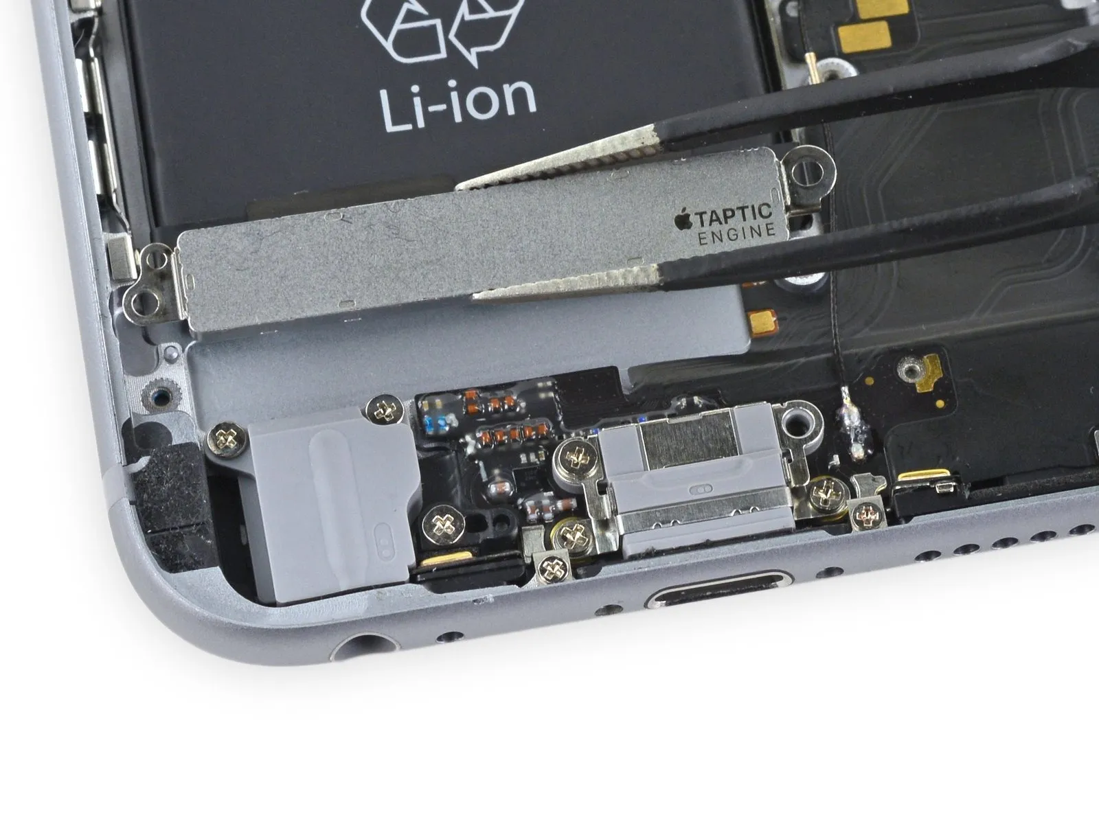
- Using the appropriate size screwdriver, detach the two screws.A measurement of one and one-half millimeters.The rear case is fastened to the Taptic Engine using Phillips screws.
Carefully detach the Taptic Engine.
Step 34

- Using a Phillips screwdriver, detach the eight screws.
Two.The specified dimension is two point nine millimeters.Secure the headphone jack with screws.
Begin the process with the number one.The specified dimension is three point seven millimeters.Secure the headphone jack bracket with screws.
Two.One point four millimeters.Fasten the iPhone's perimeter with screws.
Use a quantity of two.A measurement of one point nine millimeters.Secure the Lighting connector with screws located on both sides.
Begin the process by performing action one.The dimension is three point zero millimeters.Locate the fastener situated to the left of the connector.
Step 35
- Detach the microphone securing bracket, which is made of plastic.
Step 36

Step 37

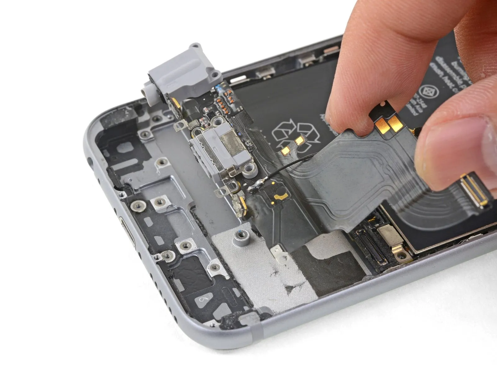
- Carefully position aUse a plastic pry tool.Carefully position yourself to access the space located along the rear case's perimeter, directly adjacent to the Lightning connector flex cable.
- Using a pick, carefully separate the flex cable from its housing by releasing the adhesive securing it.
Step 38
- Using the tool's straight edge, carefully slide it into the designated space.Use a plastic pry tool, often referred to as a spudger, to avoid scratching surfaces.Carefully separate the rear case from the Lightning connector assembly by releasing any residual adhesive.
Step 39
- Employ a 5/32-inch hex key to loosen the retaining screw, then carefully remove the component, observing that a torque of 3.2 Nm should be applied when reinstalling it.Utilize a specialized opening tool.Carefully detach the microphones from the lower rear case edge.
Step 40
- Carefully position the tip of aUse a spudger.Insert the tool into the headphone jack opening and apply pressure to release the jack from the back housing.
Step 41


- Carefully detach the Lightning connector assembly.
- Carefully detach the gasket from the original component using tweezers, then position it onto the new part.
- To ensure proper Lightning connector assembly installation or replacement, thoroughly remove any adhesive remnants from the rear case's cable area using a plastic prying tool.