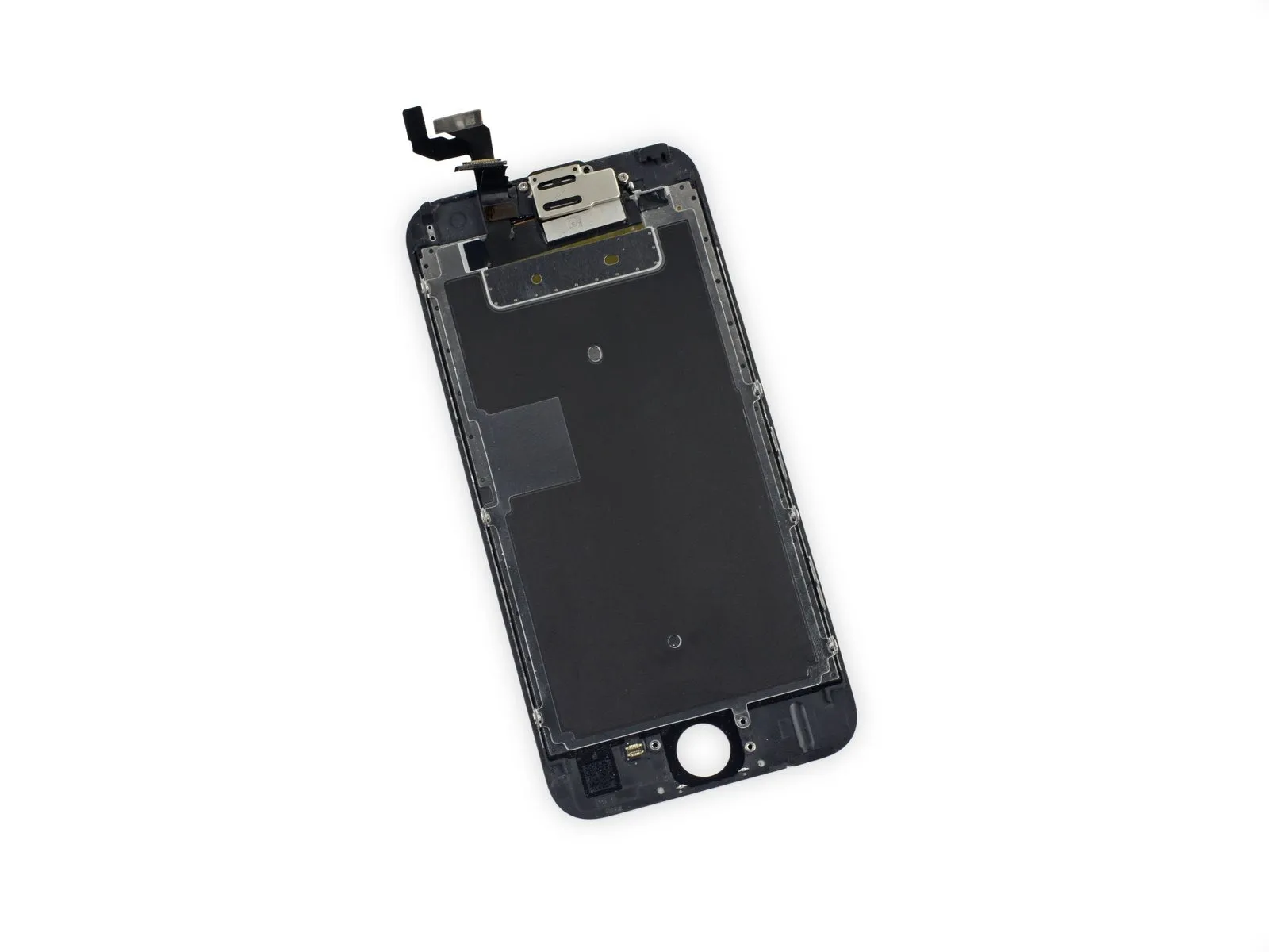
iPhone 6s Screen Replacement
To simplify the process of replacing your iPhone 6s display, the included replacement incorporates the front camera, sensor assembly, and EMI shield, eliminating the need for separate component transfers.
- Carefully detach the existing display assembly, then relocate the home button to the replacement screen.
- To ensure proper functionality, it is essential thatUtilize the capacitive fingerprint sensor to authenticate user identity.Successful operation of the fingerprint scanner depends entirely on completing this procedure.
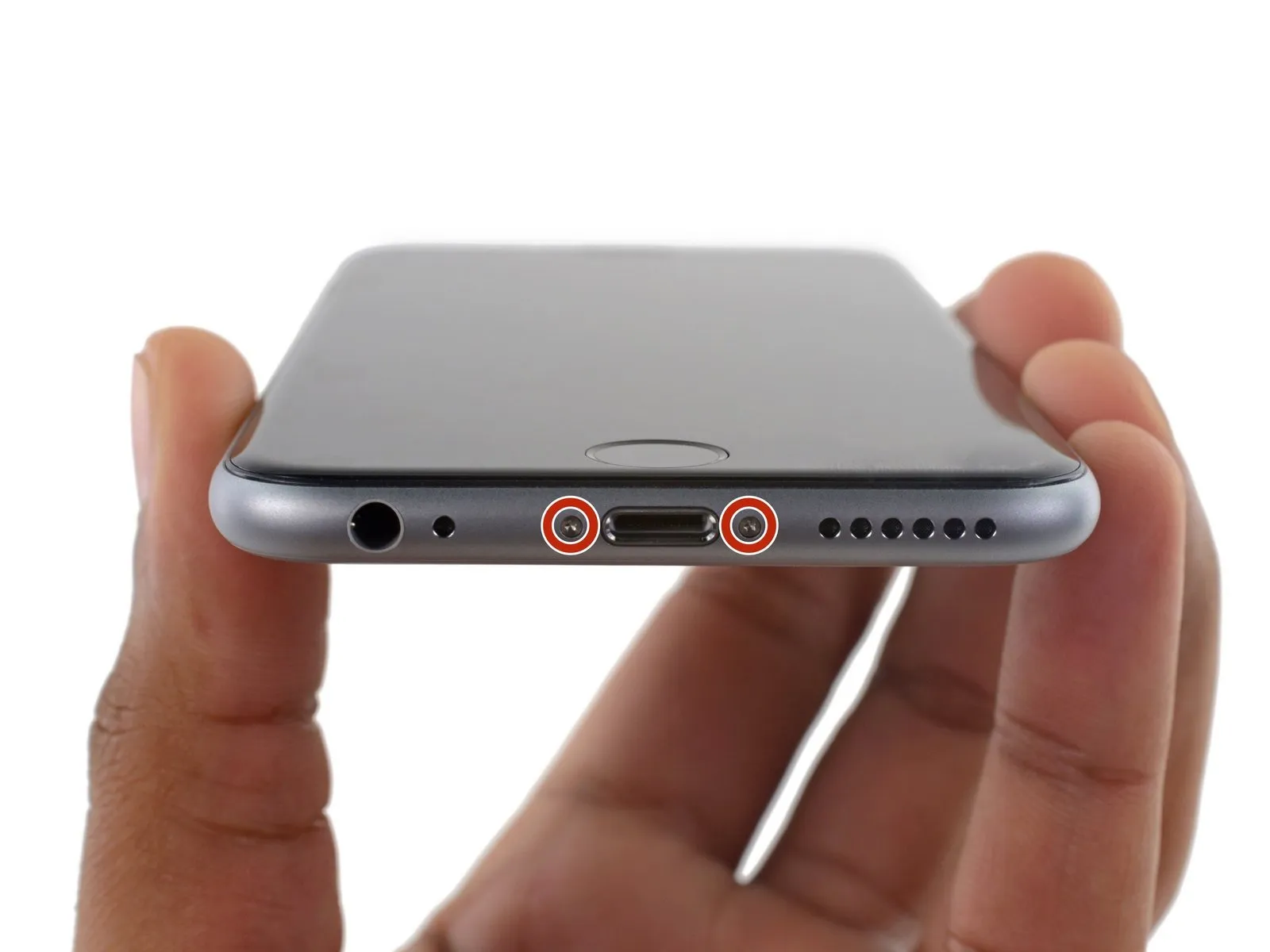
Step 1 | Pentalobe Screws
- To prevent potential hazards and ensure safe handling, ensure the battery's charge level is reduced to less than 25% prior to beginning the disassembly process.A lithium-ion battery must be fully charged.A puncture can result in fire and/or explosion.
- To prevent electrical shock or damage, ensure the iPhone is completely de-energized prior to starting the repair process.
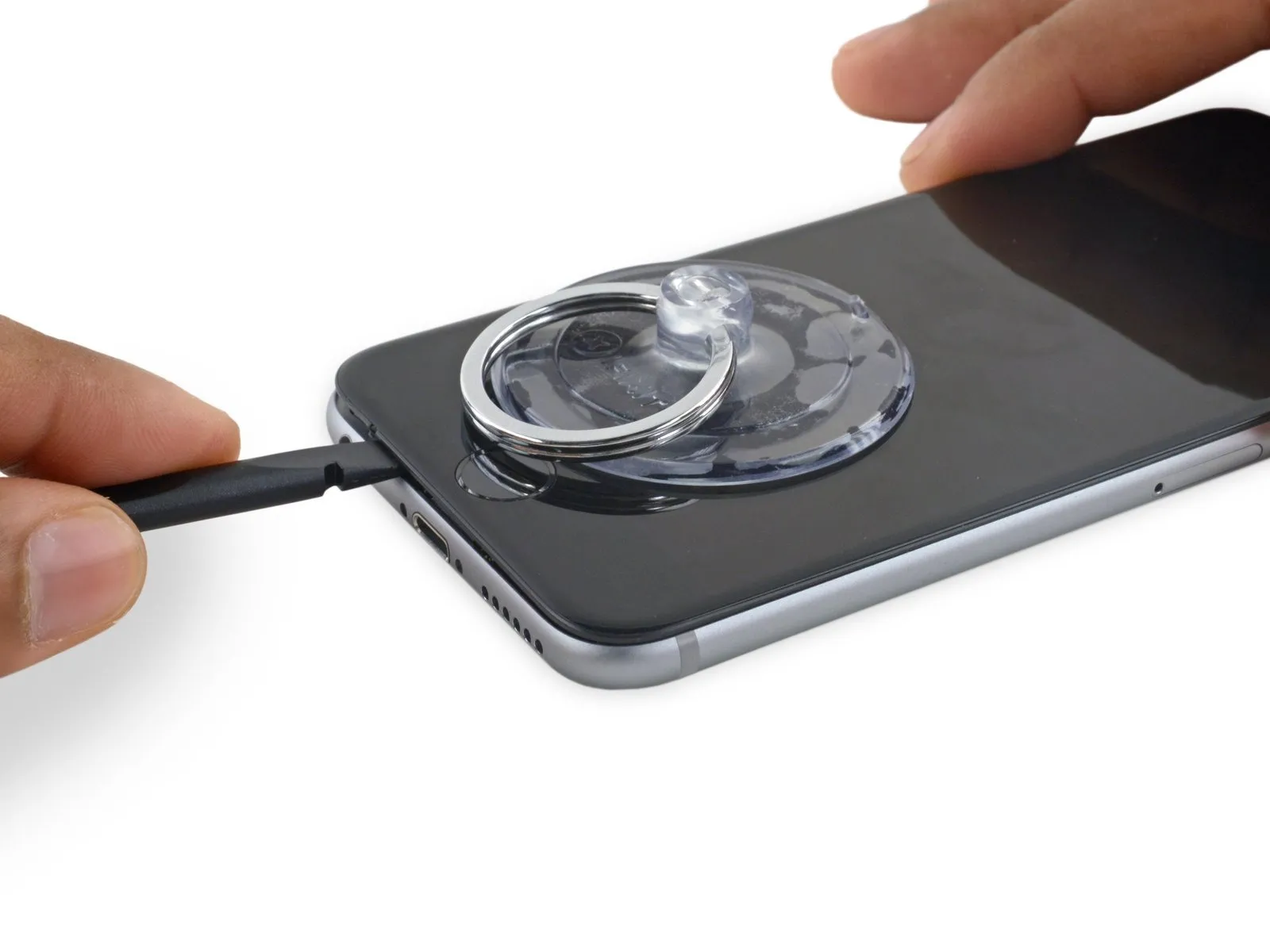
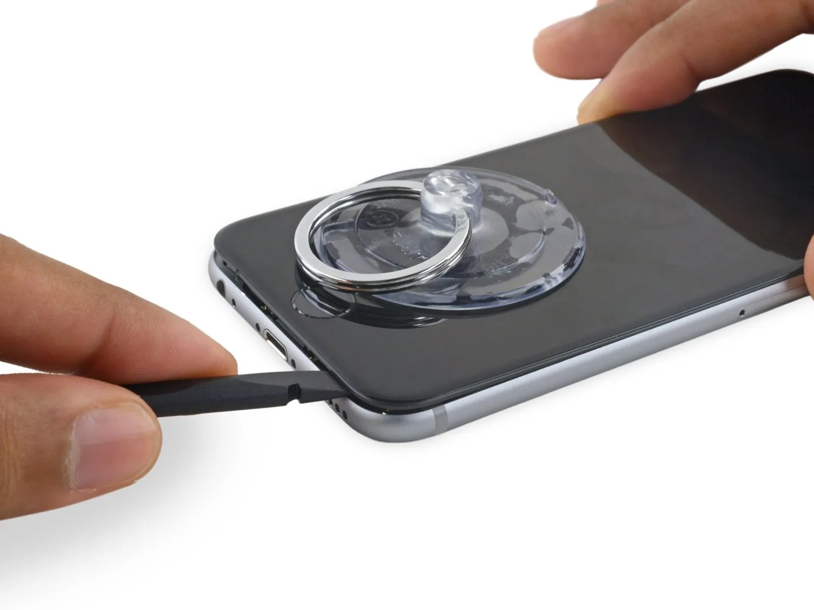
- Using appropriate tools, detach the two 3.4 mm P2 Pentalobe screws located along the bottom edge of the iPhone, one on each side of the Lightning connector.
Step 2 | Tape over the display


- To avoid injury and contain shattered fragments while you work, secure the cracked display glass with tape.
- Apply multiple layers of transparent packing tape across the iPhone screen, ensuring complete coverage of the display surface; this secures any fragmented glass and reinforces the screen's structure during the separation process.
- To safeguard your eyes from potential glass fragments that may detach during the repair process, always use safety glasses.
- Should suction cup adhesion prove challenging due to shattered glass in subsequent procedures, create a lifting handle by folding a durable tape—like duct tape—and use this to maneuver the display.
Step 3 | Anti-Clamp instructions


To simplify the subsequent opening process, the following instructions utilize the Anti-Clamp tool, a custom design; if you do not have this tool, proceed directly to the instructions three steps further down.
Refer to the included guide for detailed procedures regarding Anti-Clamp operation.
- To release the Anti-Clamp's arms, move the blue handle in a rearward direction.
- Position the arms so they clear the left or right side of the iPhone, then move them into place.
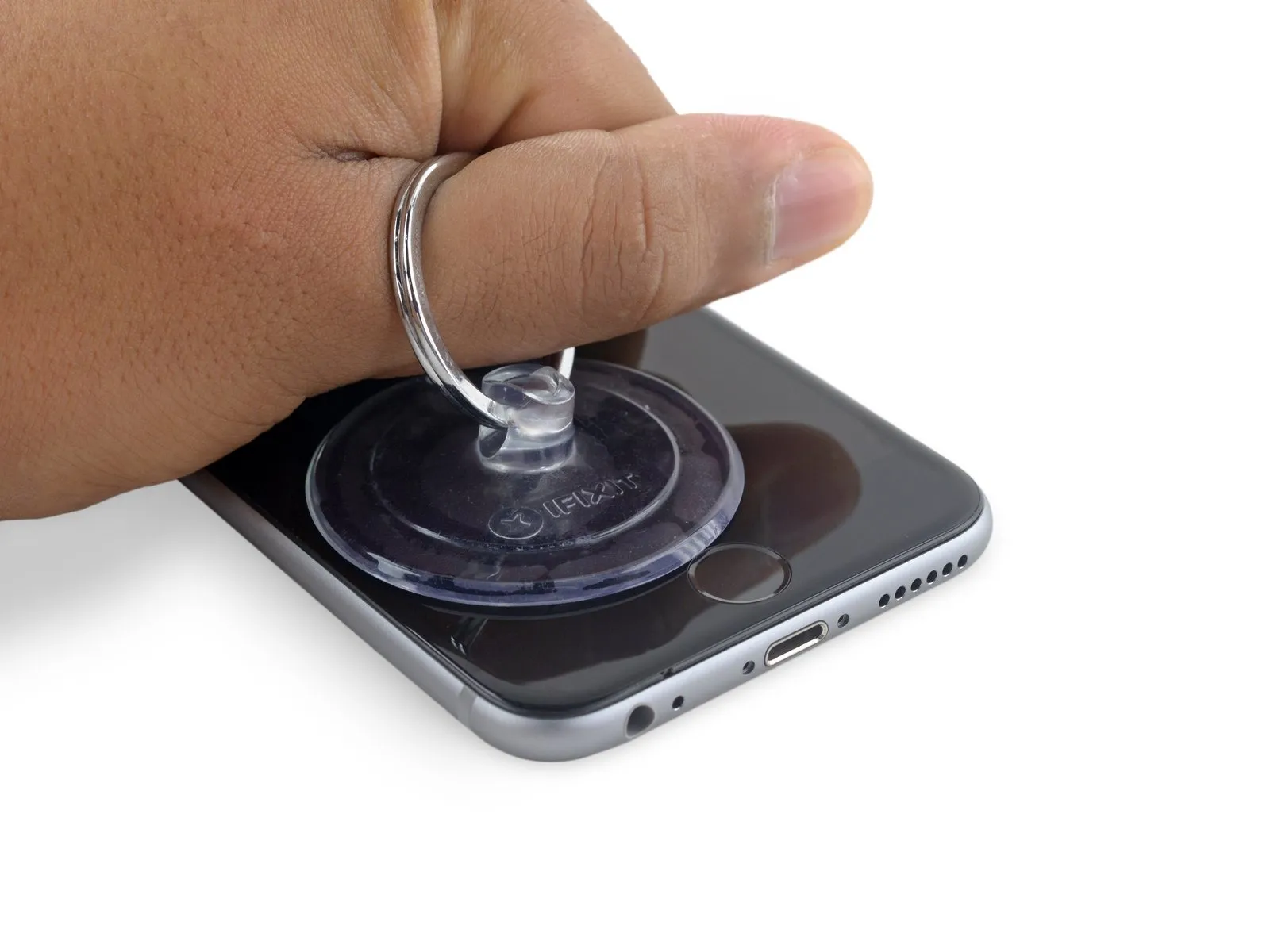
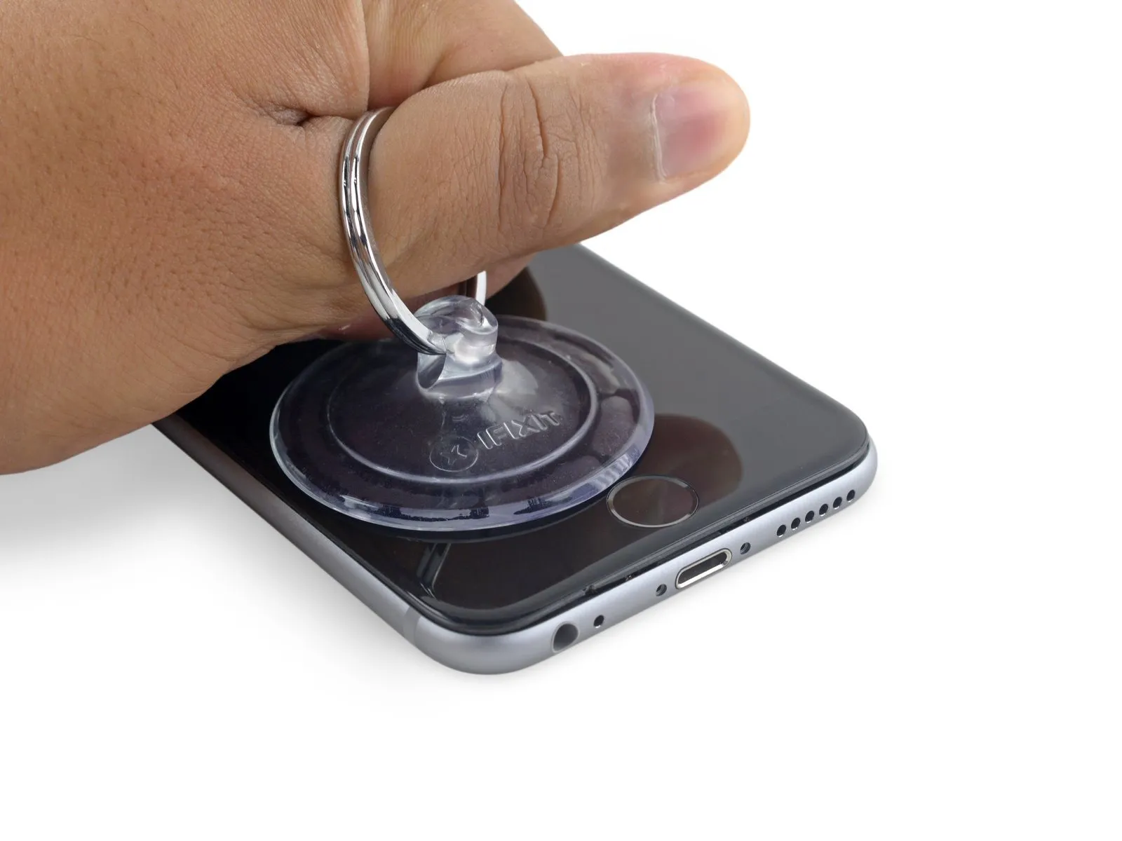
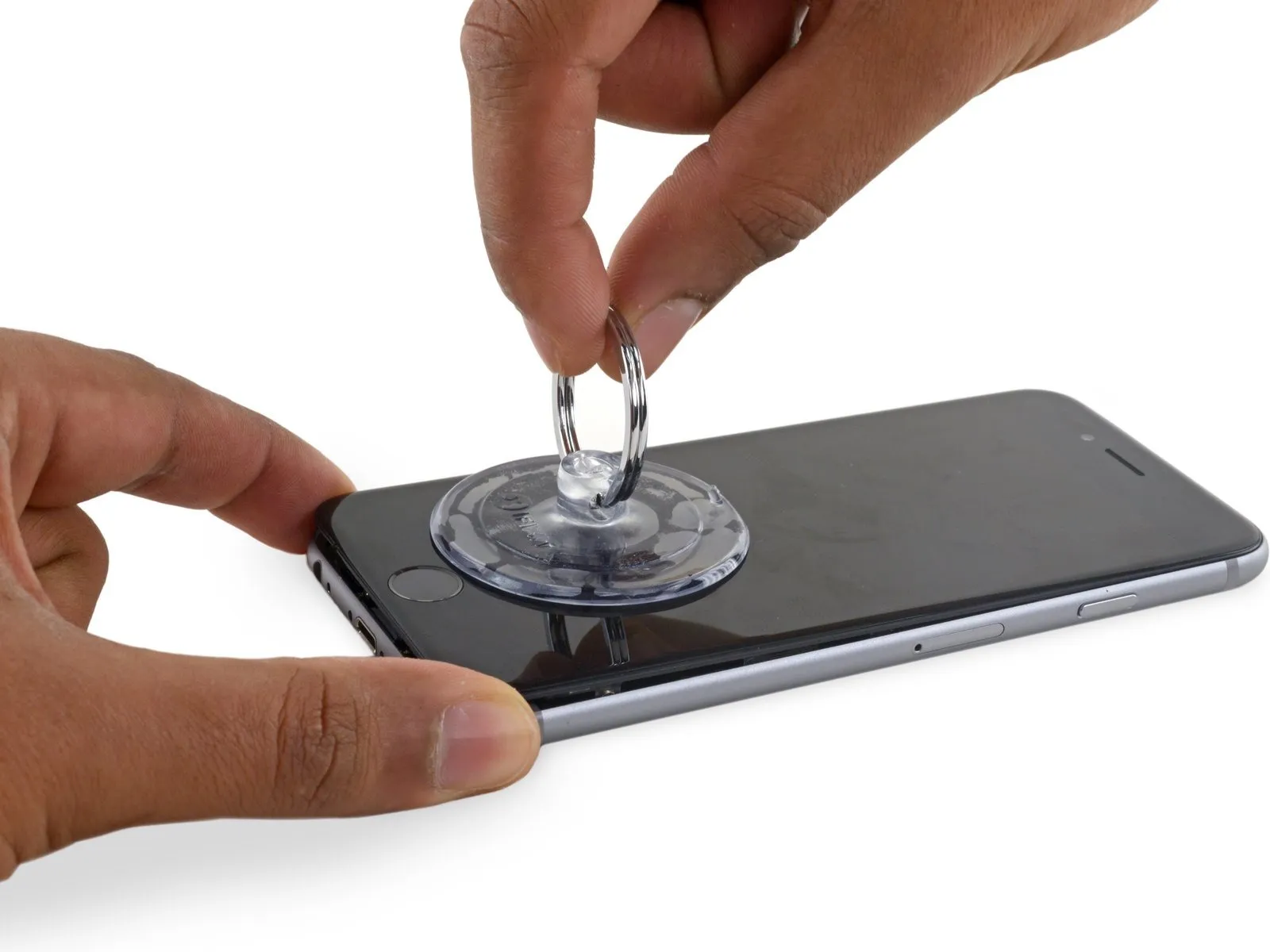
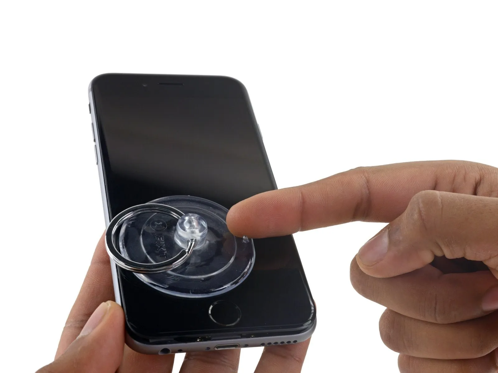
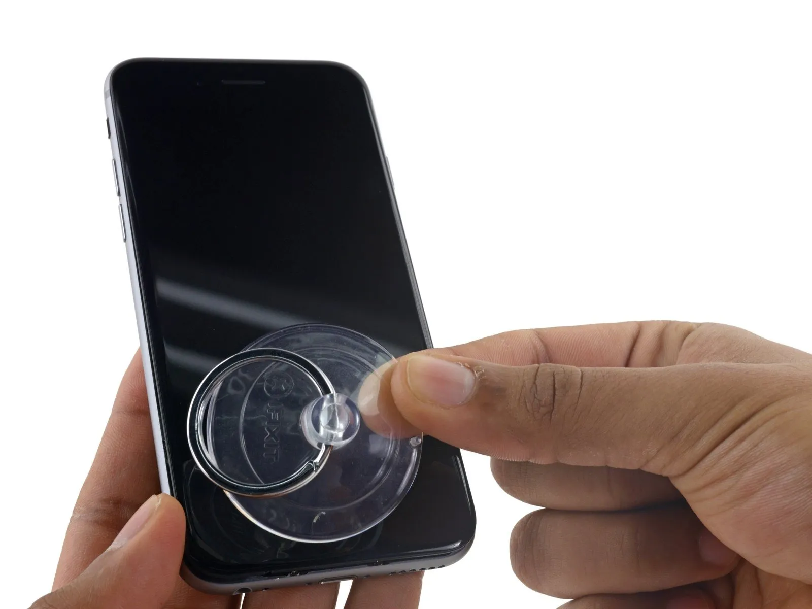
- Affix a suction cup to the iPhone’s front surface, close to the lower edge and directly over the home button, and secure another suction cup to the rear surface in a similar location.
- Apply vacuum by pressing the cups firmly against the surface needing treatment.
- To improve the Anti-Clamp's adherence if the iPhone's exterior feels excessively smooth, apply adhesive tape to provide increased friction.
Step 4


- To secure the arms, advance the blue handle in the direction indicated.
- Rotate the handle a full 360 degrees, observing the cups as they expand. Maintain parallel alignment between the suction cups; if misalignment occurs, gently release the suction cups and reposition the arms to restore proper orientation.
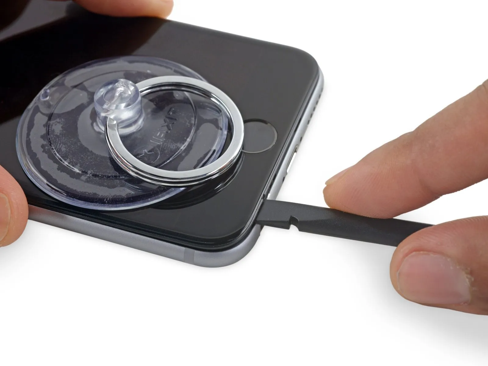
- Once sufficient space is created by the Anti-Clamp, slide a separation tool beneath the display panel.
- To ensure adequate separation, incrementally adjust the handle by 90 degrees, pausing for several seconds after each adjustment; avoid movements exceeding 90 degrees to prevent damage, allowing the Anti-Clamp to function properly.
Step 5 | Opening Procedure
- In the absence of an Anti-Clamp tool, proceed with the subsequent three steps to utilize a suction handle.
- Use a heat gun, set to a low temperature, to gently warm the bottom of the iPhone's display assembly.Use the iOpener.Apply heat with a hair dryer, maintaining its proximity to the area for approximately one minute.
- Applying heat will loosen the adhesive that holds the display in place, facilitating separation.
Step 6
To access the 6s display, carefully release the adhesive strip encircling its edge; replacement adhesive strips should be prepared beforehand if desired. The repair can be performed without fresh adhesive, and operational performance should remain unchanged.
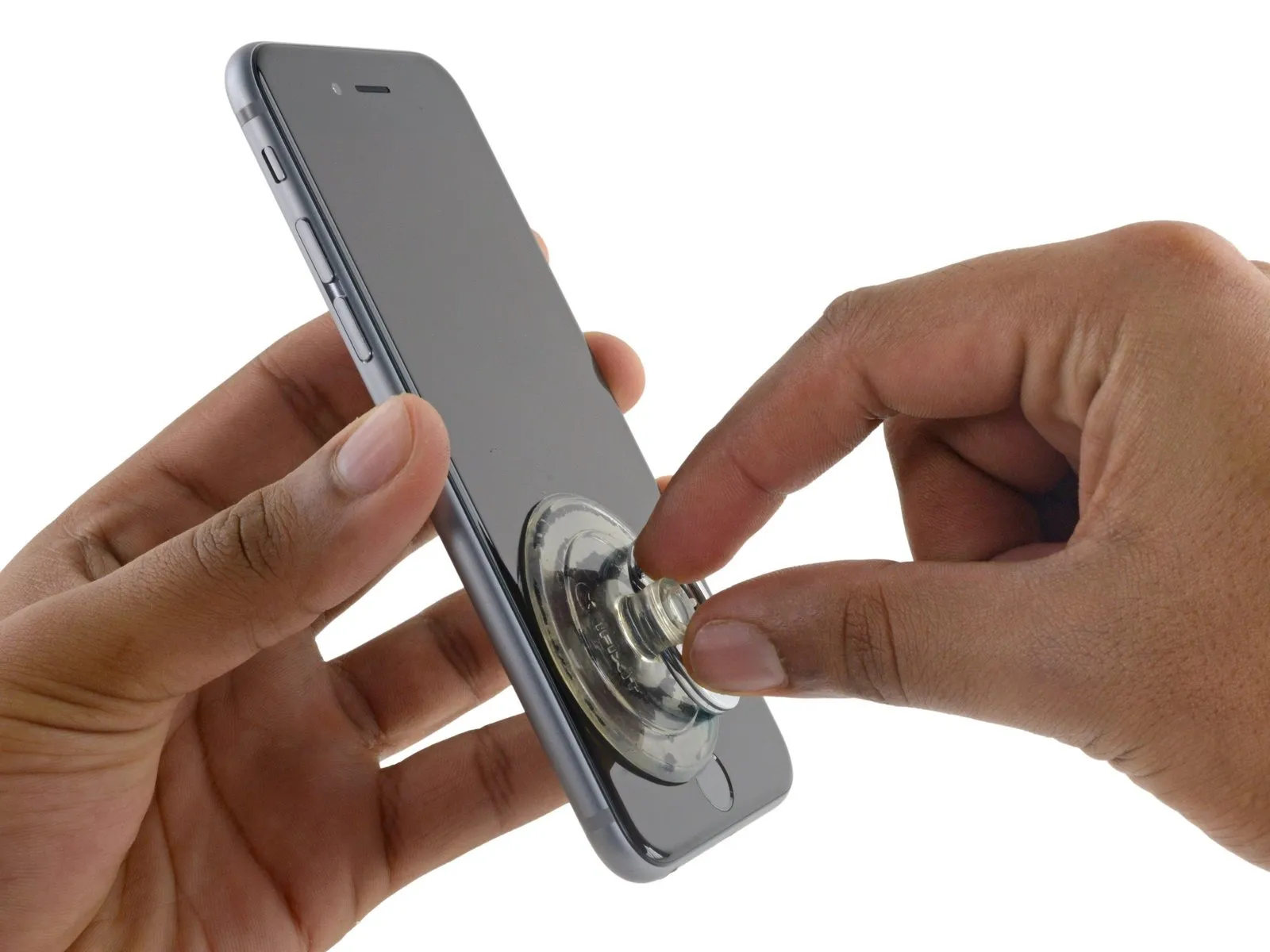
- Securely attach a suction cup to the display assembly's lower-left corner.
- Avoid positioning the suction cup directly on the home button.
- To facilitate suction cup attachment on a severely cracked display, apply a sheet of clear packing tape across the damage; as an alternative, a robust adhesive tape can be used directly. As a last resort, superglue can secure the suction cup to the fractured screen.
Step 7
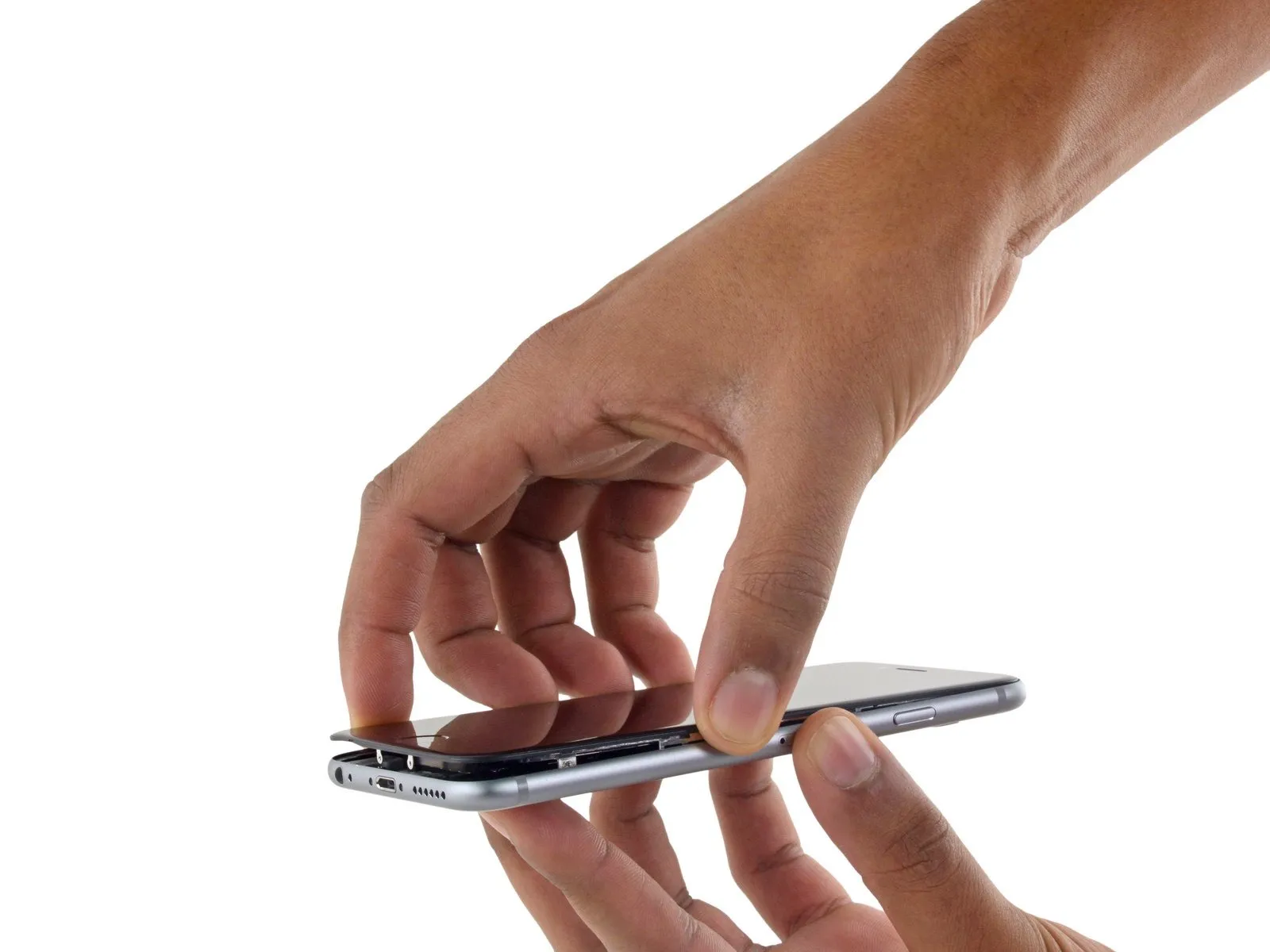
Apply steady, even force to lift the suction cup, generating a small separation between the front panel and the rear case.
Exercise caution and use steady, even pressure during installation; the display unit's fit is significantly snugger than typical device components and secured with adhesive.
To avoid display assembly damage, use minimal force to separate the display assembly from the rear case, creating a narrow space.
To resolve potential issues, apply warmth to the device's front surface with a heat source.Use a device like an iOpener to apply gentle, even heat across the perimeter of the enclosure.Apply heat from a hair dryer or heat gun to the display edges until the surface reaches a temperature just beyond comfortable touch, which facilitates softening the adhesive bond.
Step 8
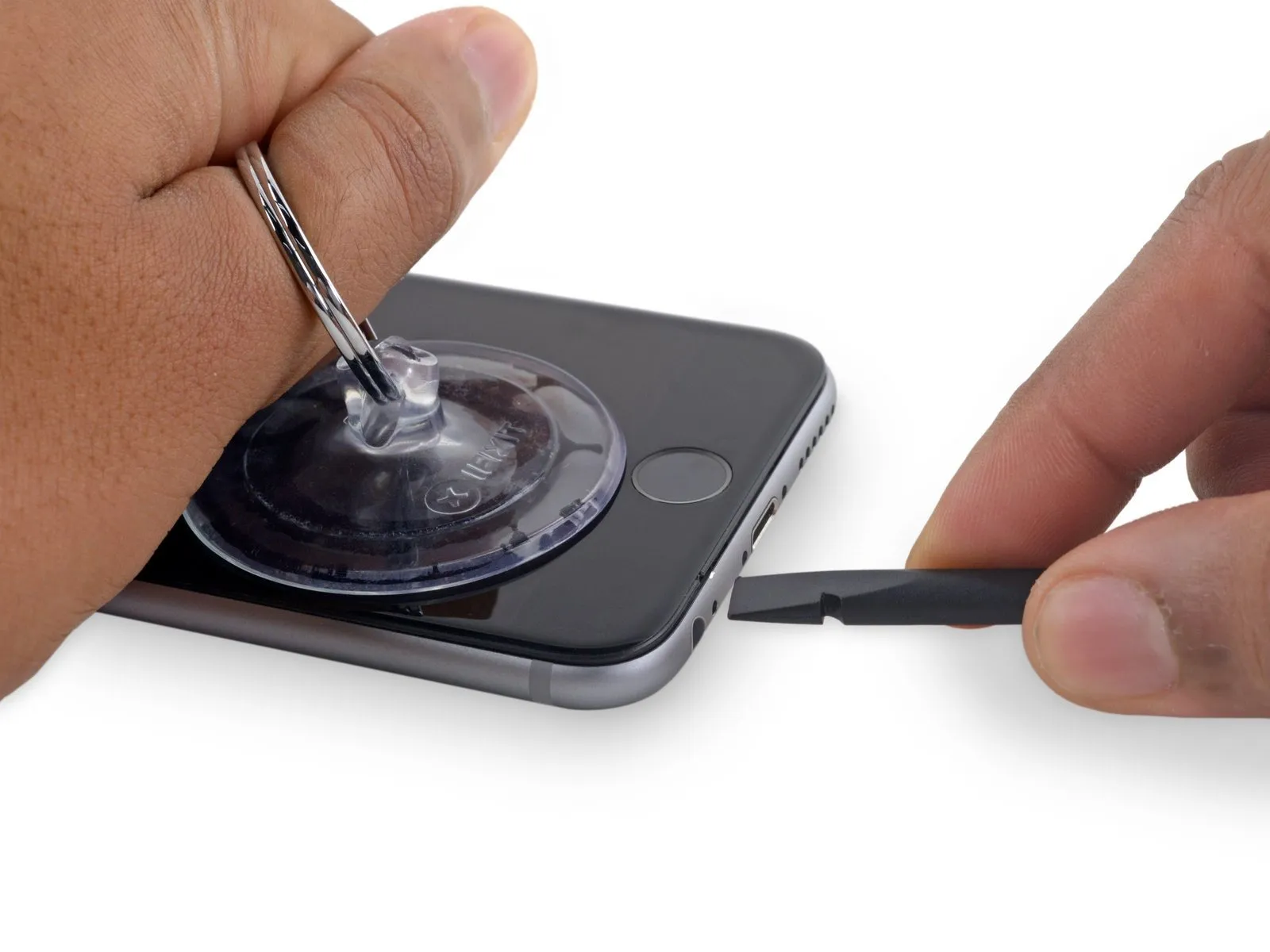
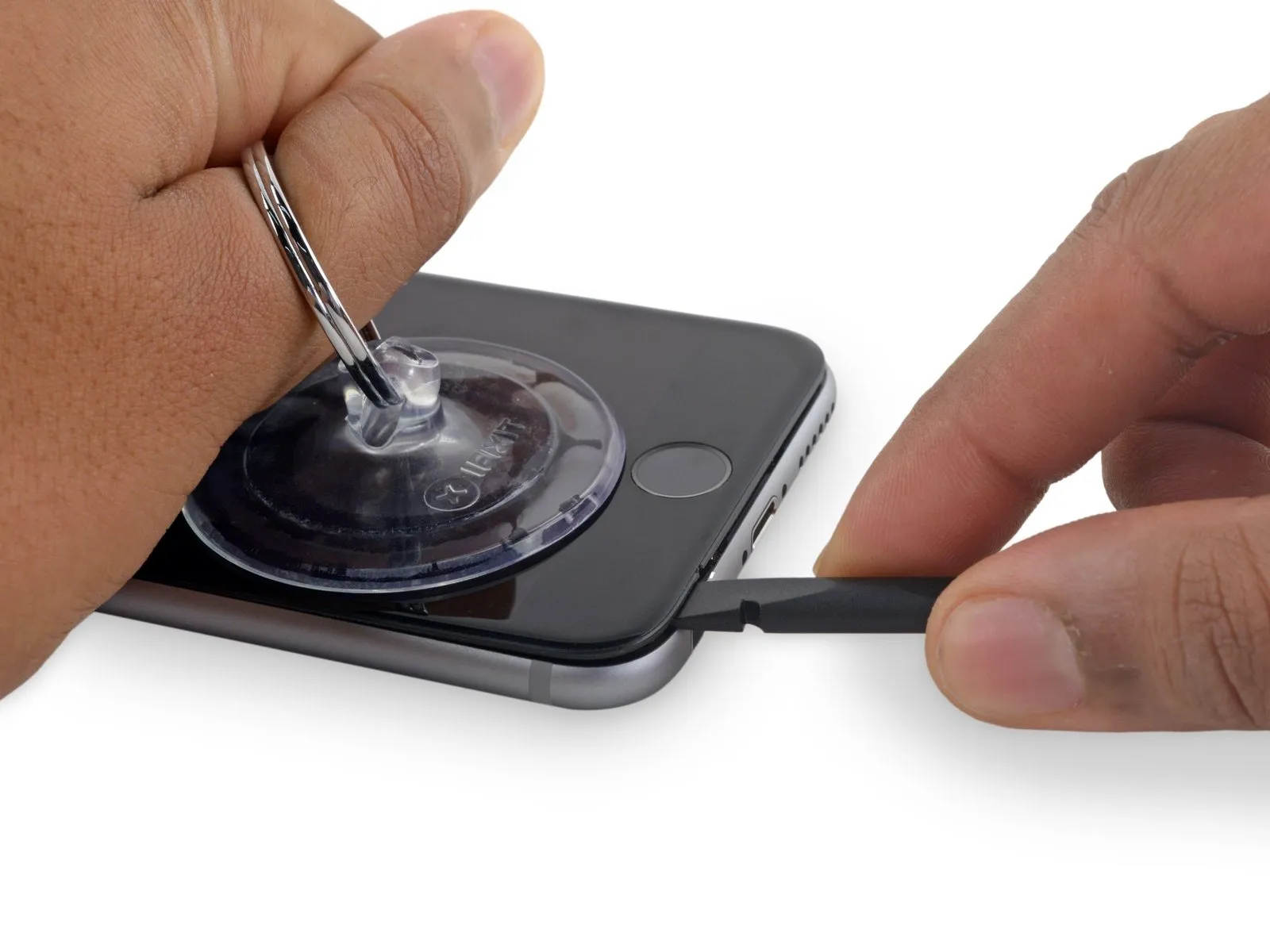
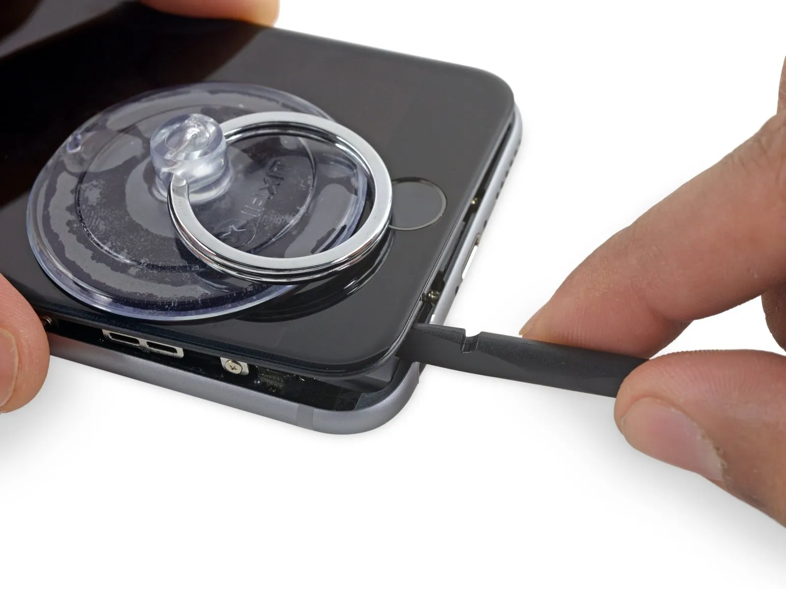
To initiate separation of the device's housing, carefully insert a prying tool into the indentation located on the bottom surface of the display, directly above the headphone jack, as this area presents the lowest risk of damage.
Using a spudger, insert its flat end into the separation between the display and the back cover, positioning the insertion point immediately over the headphone jack.
Step 9
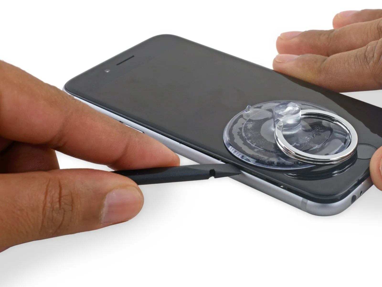
- Using a spudger, gently increase the separation between the front panel assembly and the phone's main body.
Step 10
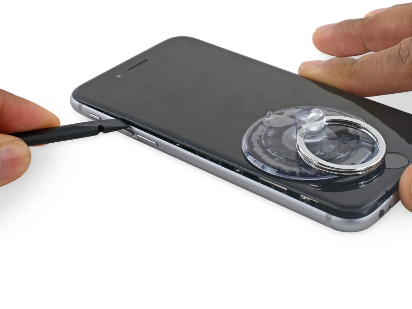
- Using a spudger, carefully slide the flat tip into the gap located on the phone's left side, separating the display assembly from the rear case.
- Using a spudger, carefully work it along the phone's edge to loosen the adhesive and release the retaining clips.
Step 11
- Using the spudger, carefully re-engage it along the lower edge of the device, the area previously separated.
- Using a spudger, gently move it horizontally across the phone's lower edge.
Step 12
- Using a spudger, carefully work along the right edge to release the adhesive bond and disengage the display clips securing the iPhone.
Step 13

- Carefully leverage the suction cup to separate the display assembly, ensuring the remaining adhesive bond is released.
- To prevent damage, limit the display's opening angle to a maximum of 90 degrees; the three cables connecting it to the top edge are susceptible to breakage if extended beyond their natural length.
Step 14
To detach the suction cup, grasp the small projection located on its upper surface and lift, releasing it from the front panel.
Step 15
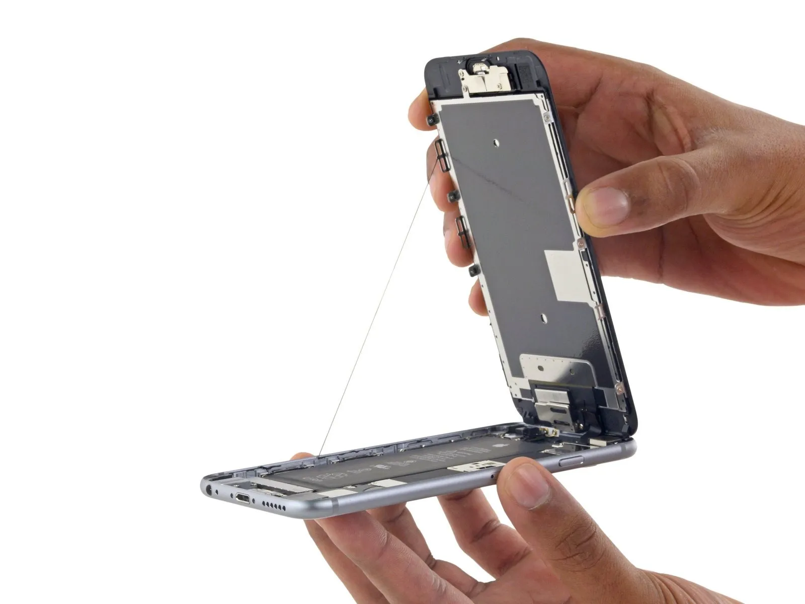
- Using the upper front panel's clips as a pivot point, carefully raise the display assembly to separate the phone's housing.
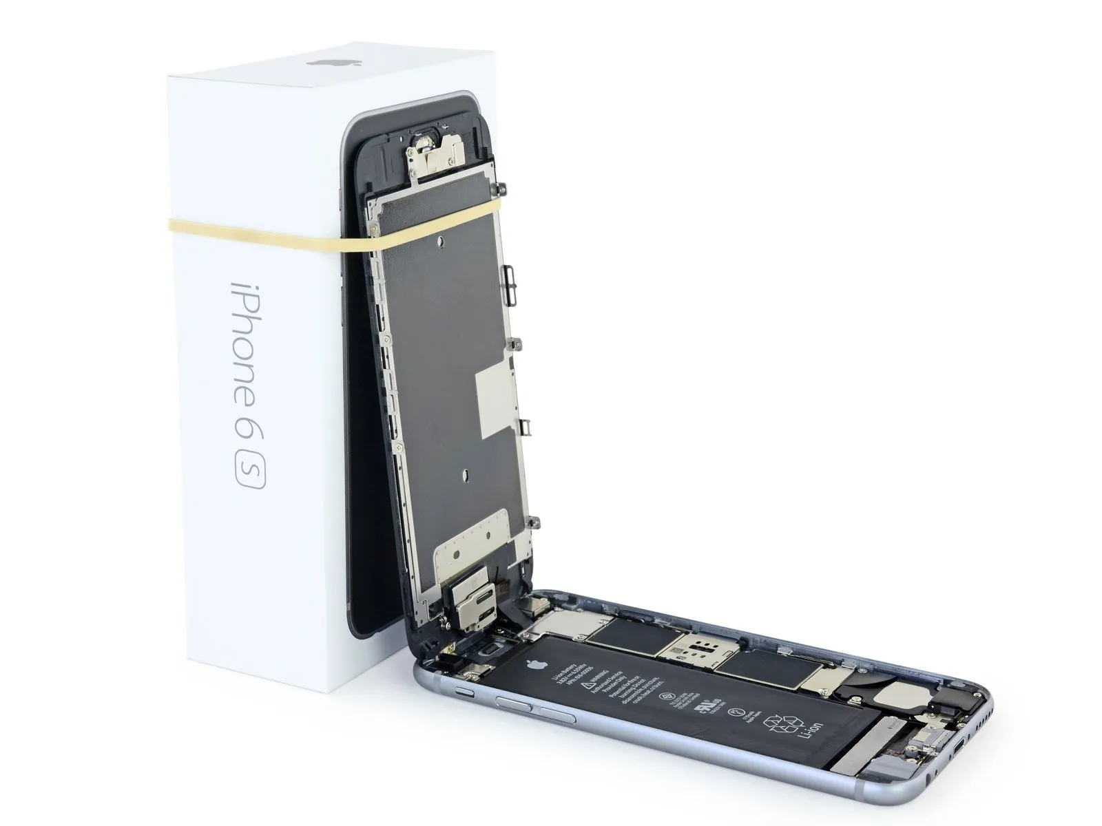
- Carefully position the display at a roughly 90-degree angle, then secure it in an upright position using a support to allow for hands-free access during the repair process.
- To avoid stressing the display's wiring during the repair process, secure the display with a rubber band.
- As a temporary measure, an unopened, standard-sized canned drink can substitute for the display during the repair process.
- If you intend to substitute fresh adhesive along the display's perimeter during reassembly, stop at this point.
- To ensure proper alignment during reassembly, guide the camera-side edge of the screen body beneath the main body's edge, positioning the screen frame's hooks beneath the main body's rim. Then, gently press the frame towards the camera end to facilitate cover closure and secure clipping.
- Ensure these clasps are positioned beneath the phone's outer edge, as they function as retention features rather than hinges; this placement allows the screen to smoothly and quietly return to its closed position, engaging with a gentle snap.
- To reinstall the screen, begin by applying pressure along the top right corner, working downwards, then repeat the process on the left side.
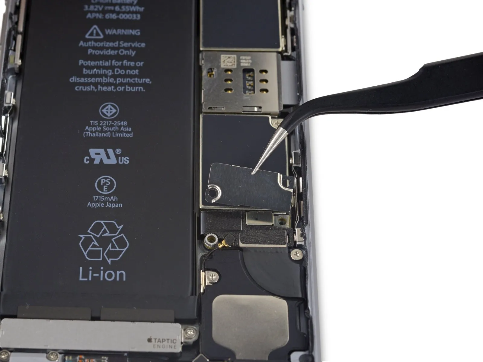
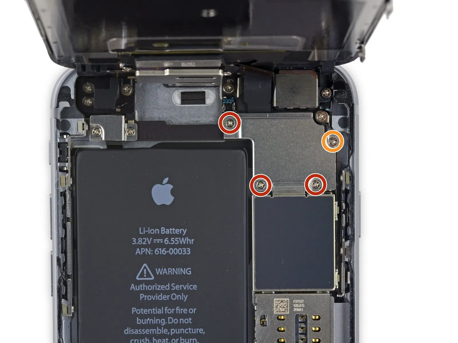
Step 16 | Battery Connector
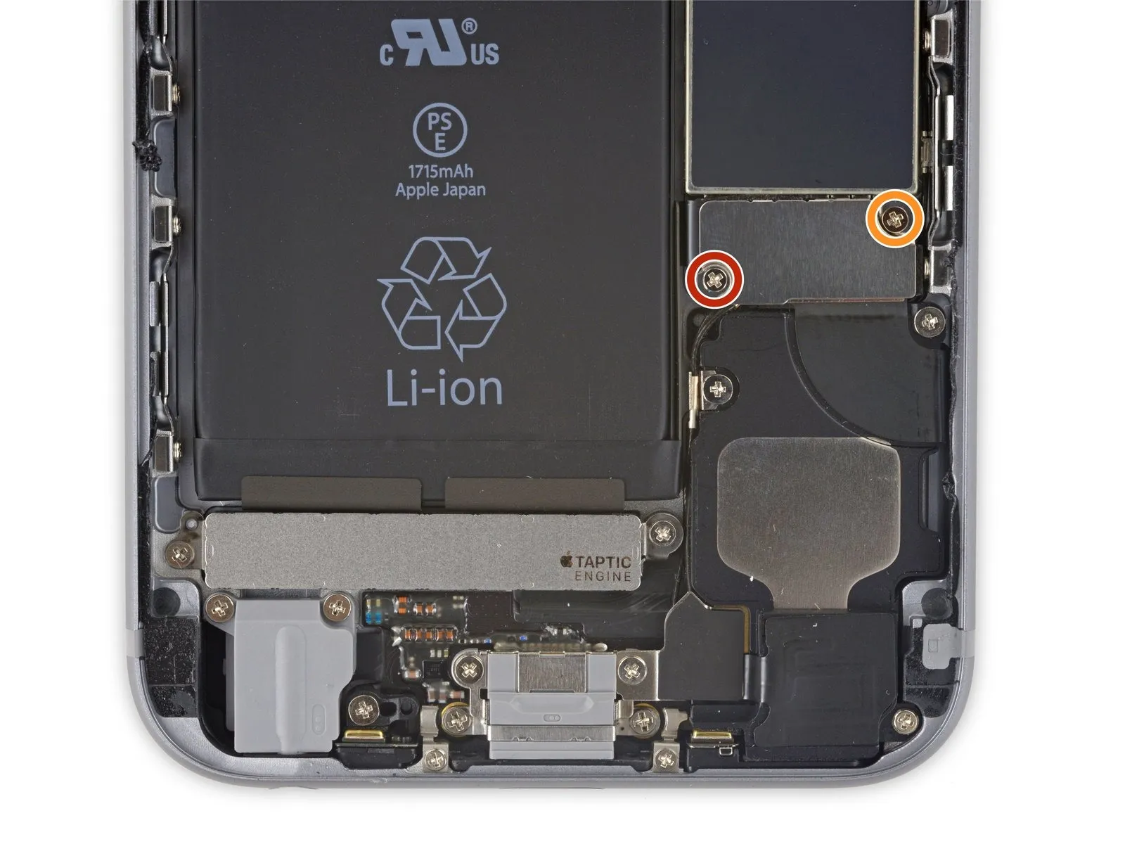
Detach two.Use a screwdriver with a Phillips head.Use screws with these lengths to fasten the battery connector bracket:
- A screw with a 2.9 mm diameter is required.
- A screw with a 2.2-millimeter head diameter is required.
Carefully note the location of every screw during disassembly, as reassembly requires placing each one in its original position to prevent potential iPhone damage.
Step 17
Step 18

Step 19
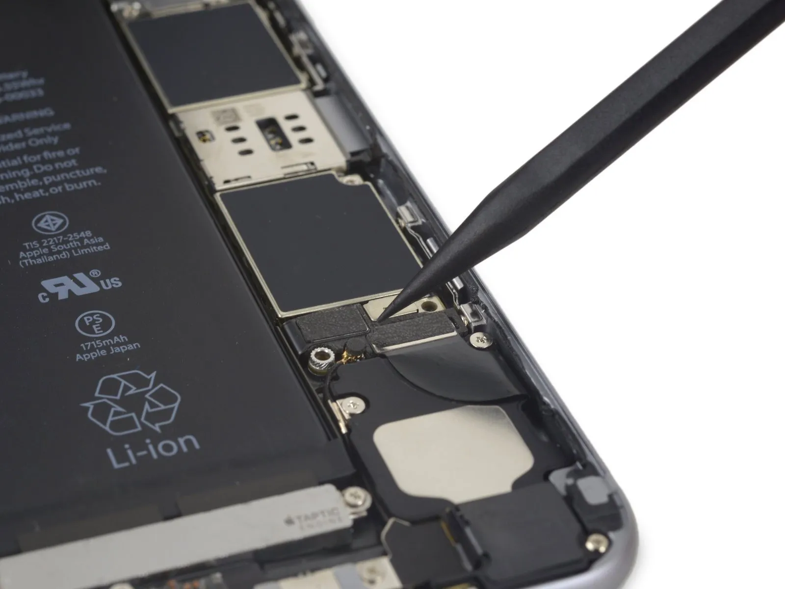
Step 20 | Unfasten the display cable bracket
- Use three screws, each measuring 1.2 millimeters.
- A screw with a 2.8-millimeter head diameter is required.
Step 21
Step 22
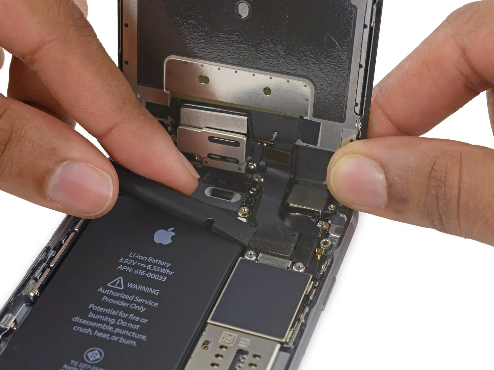
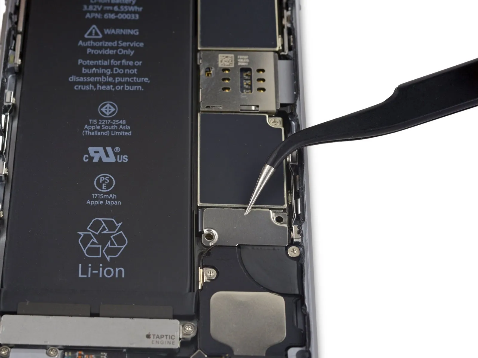
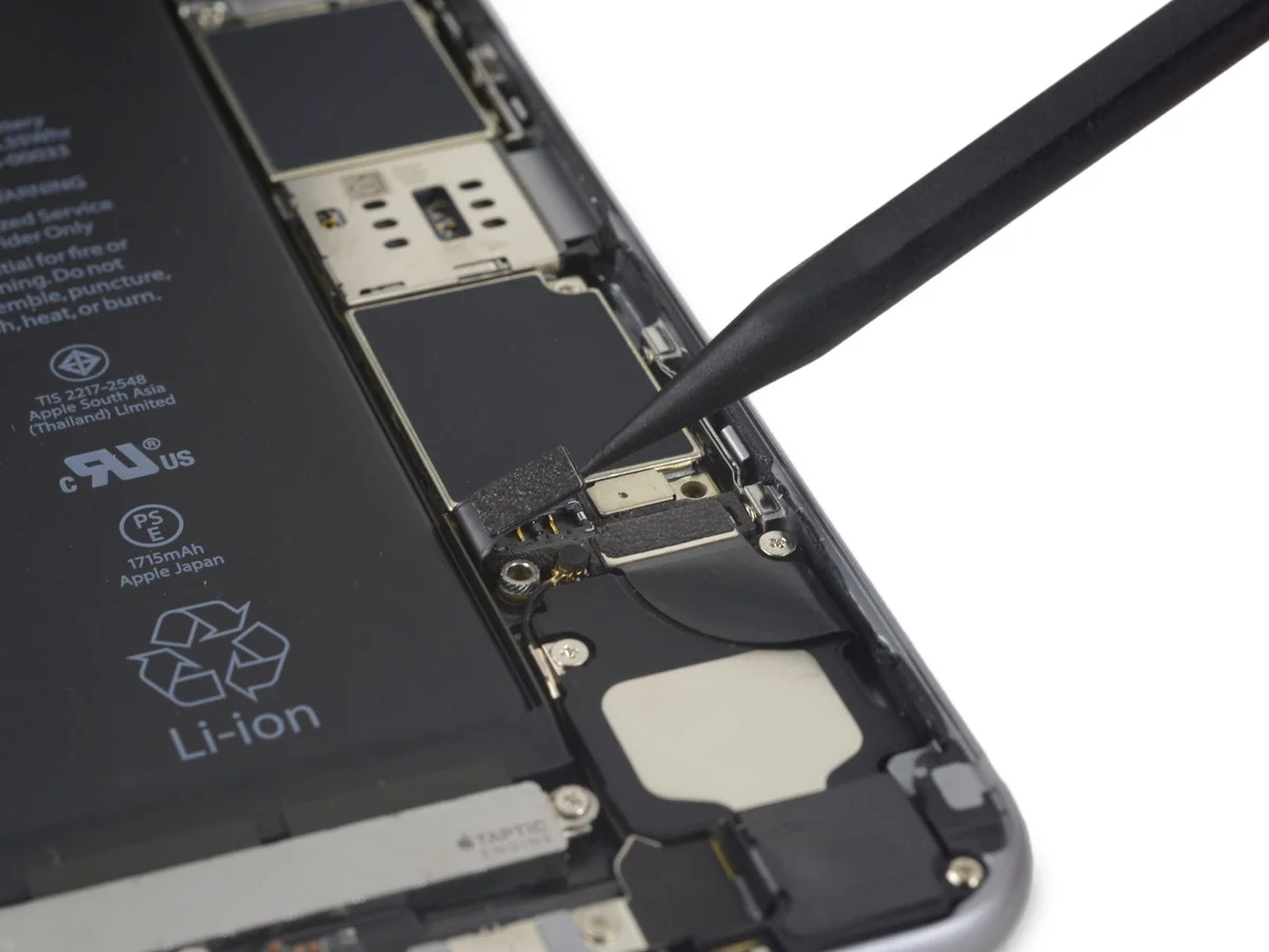
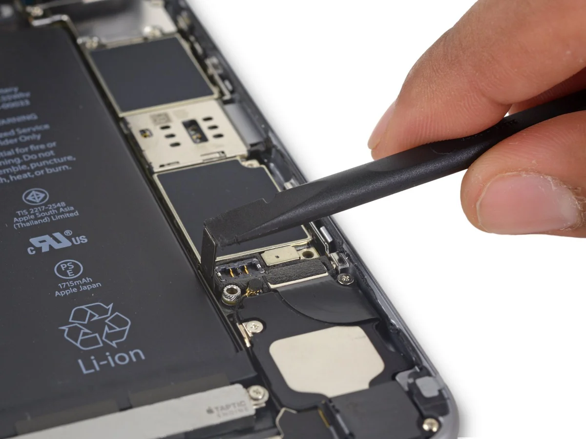
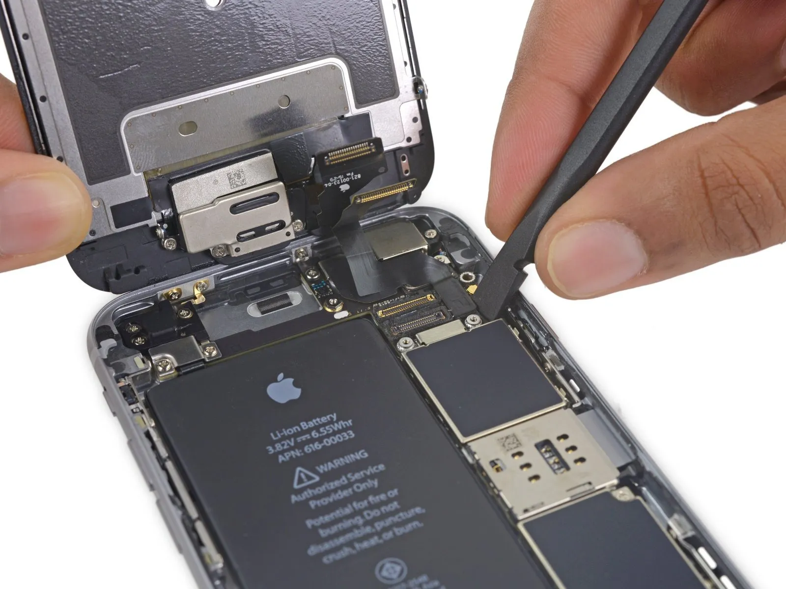
- Carefully detach the front camera flex cable from its connector on the logic board by applying upward pressure with a spudger or a clean fingernail.
Step 23
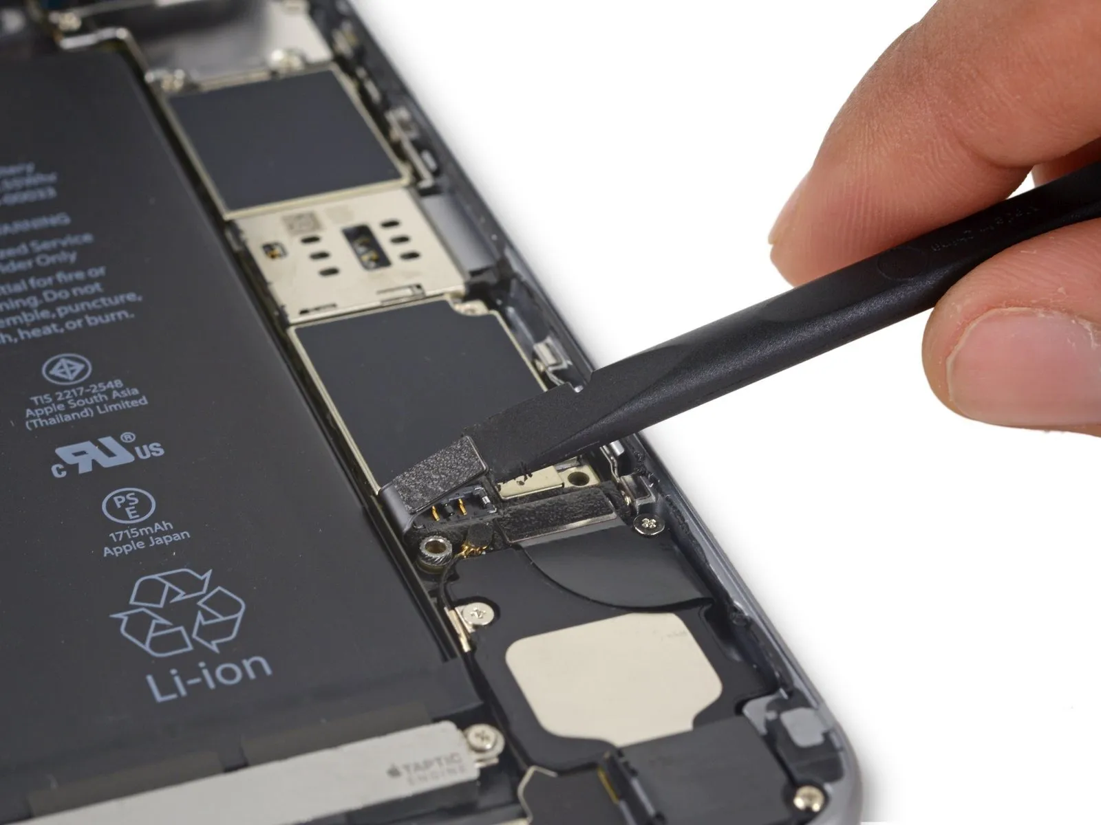
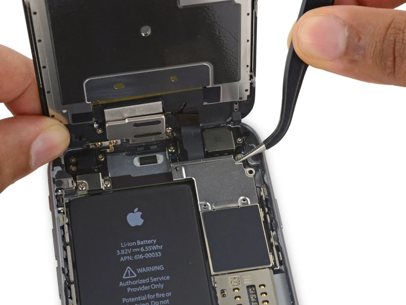
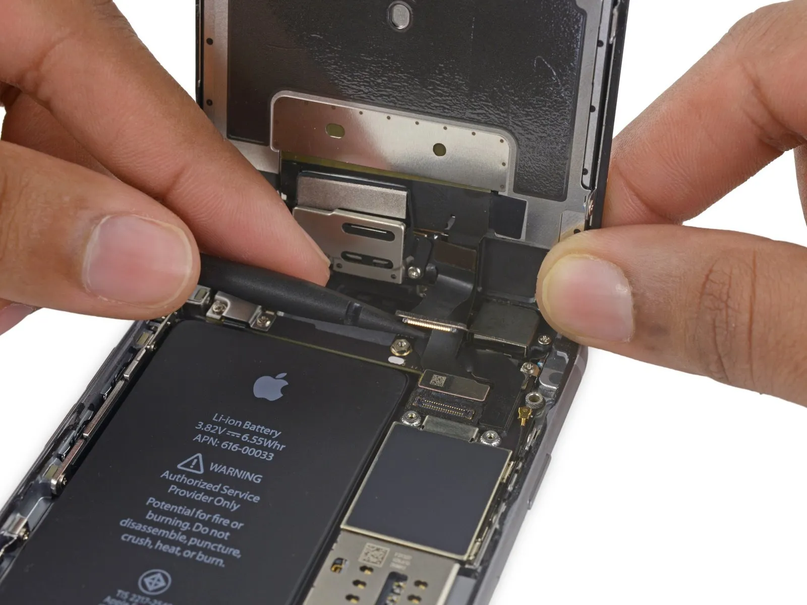
- Using a prying tool, carefully separate the digitizer cable from its connector on the logic board by applying upward force.
- To ensure proper alignment and prevent damage, apply pressure to opposing ends of the digitizer cable connector during reconnection; avoid central pressure, as this may warp the component.The display's touch functionality is impaired due to damage to the digitizer..
Step 24
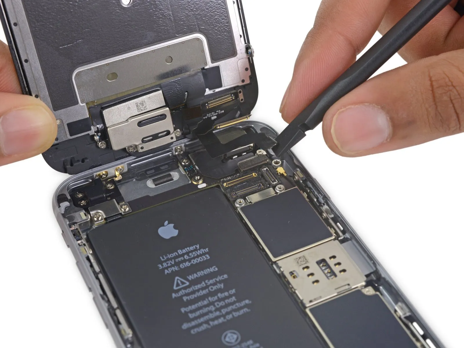
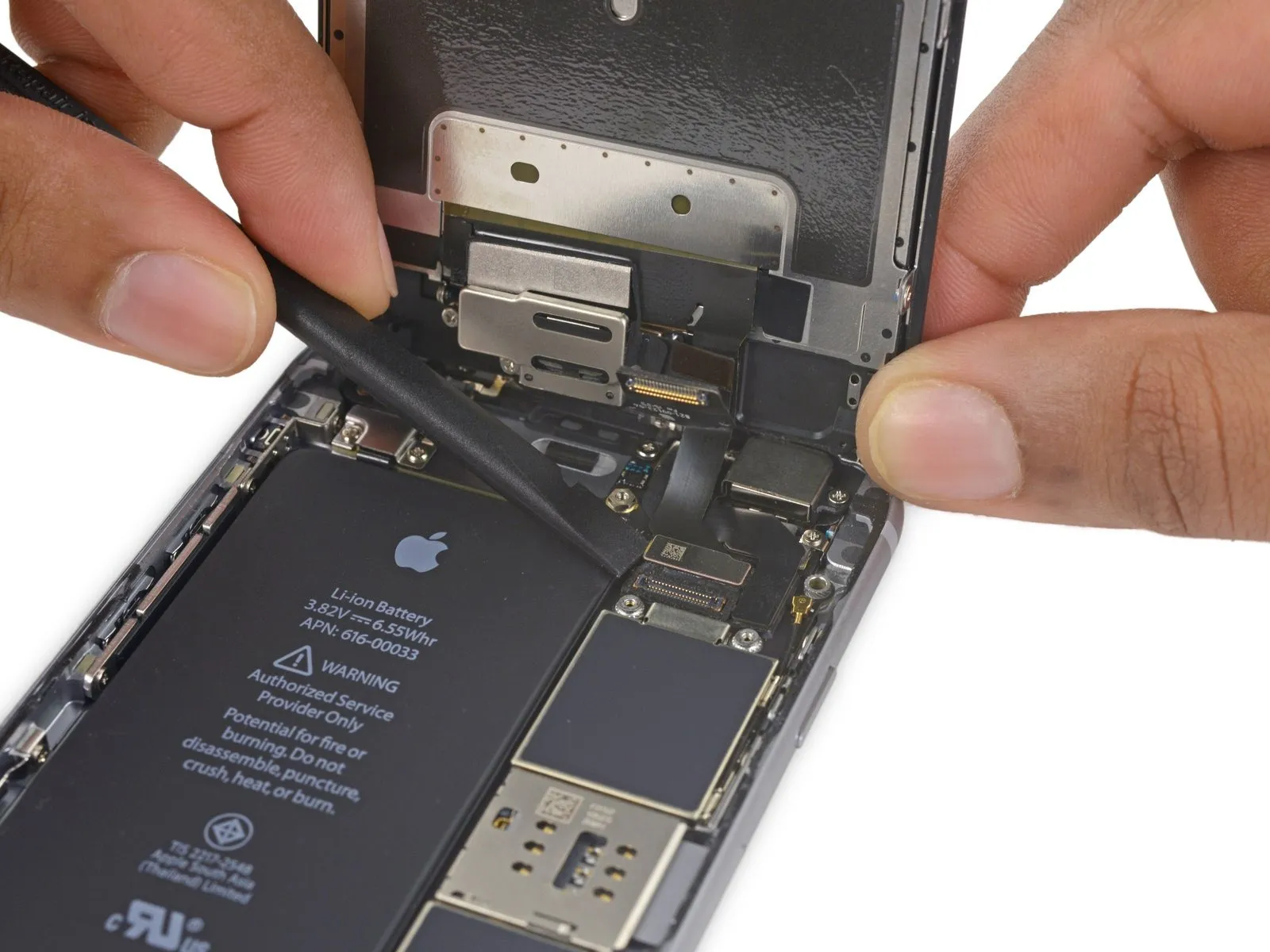
- Prior to either detaching or reattaching the cable in this procedure, ensure the battery is disconnected.
- Using a prying motion, carefully detach the display cable from its socket on the logic board, ensuring it moves vertically.
Step 25
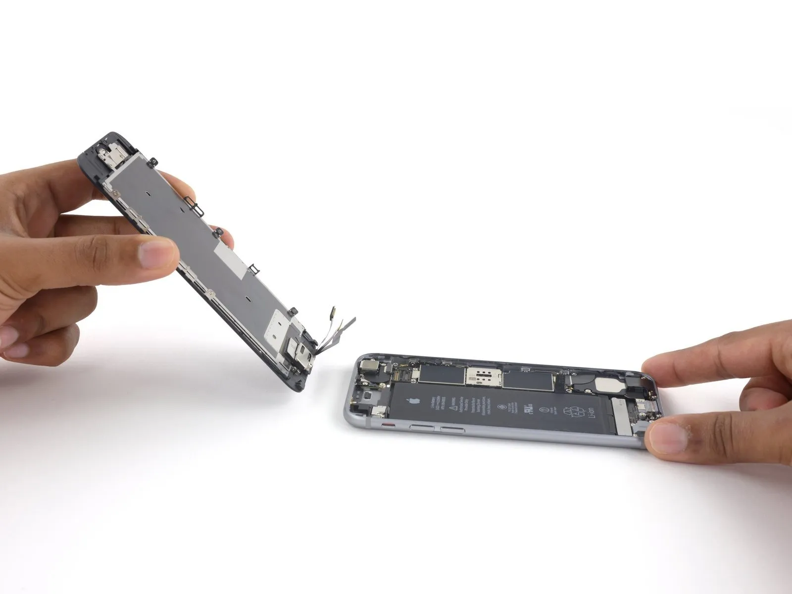
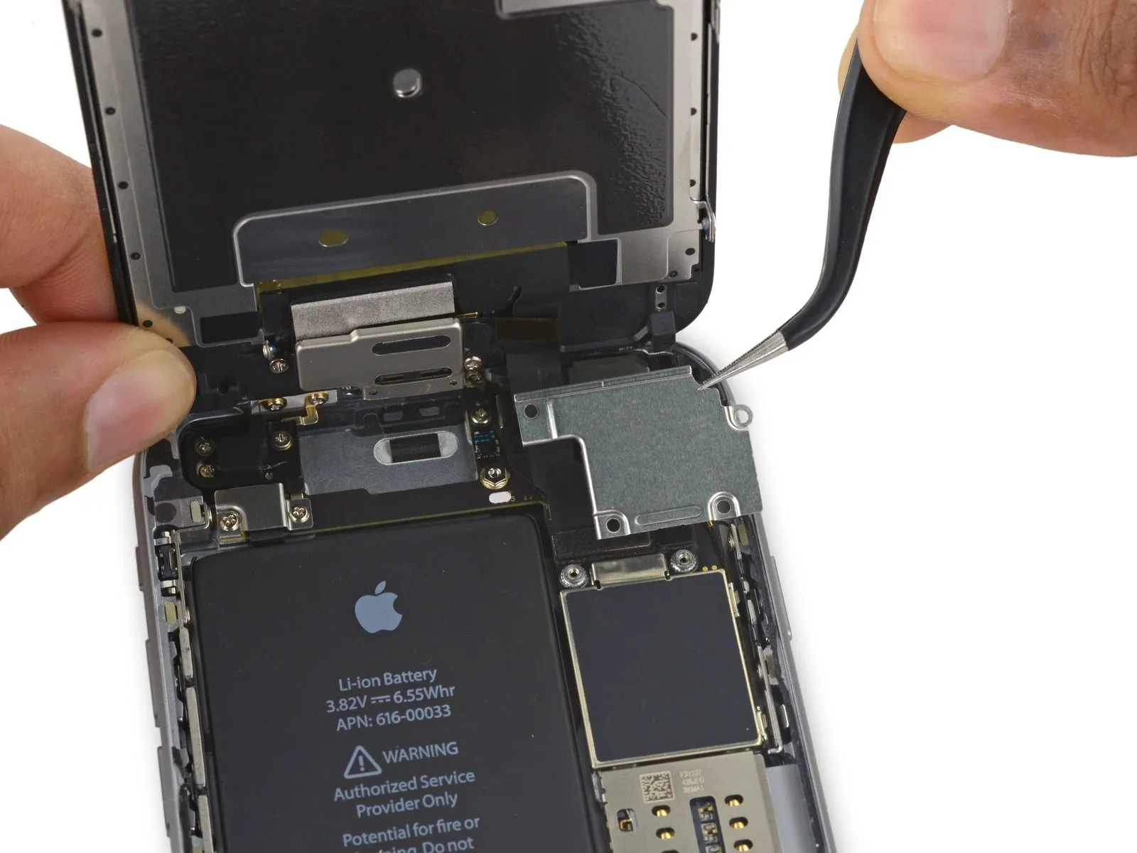
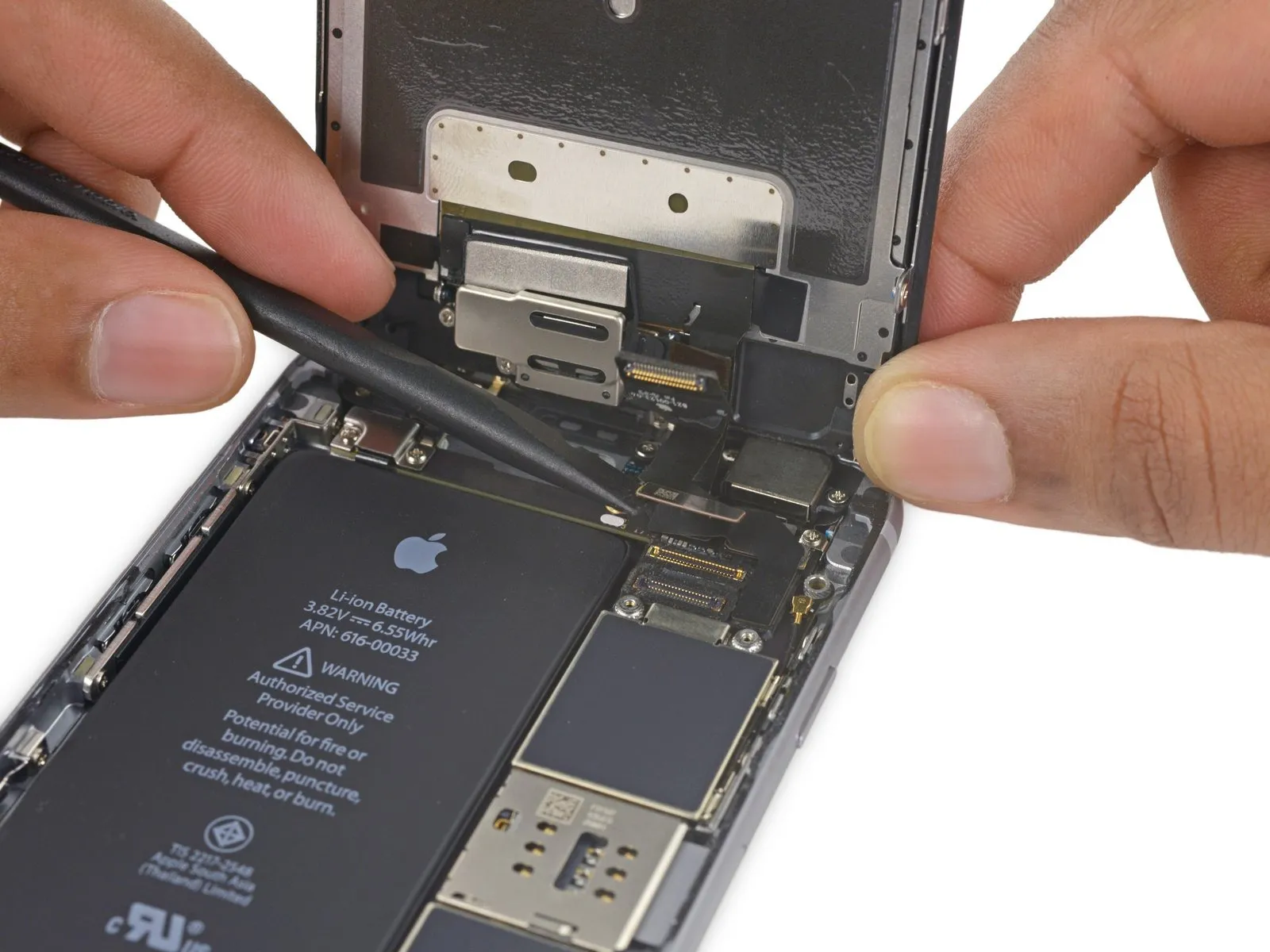
- Carefully detach the display assembly, ensuring all connections are released and fasteners are removed.
- If you intend to substitute fresh adhesive along the display's perimeter during reassembly, stop at this point.
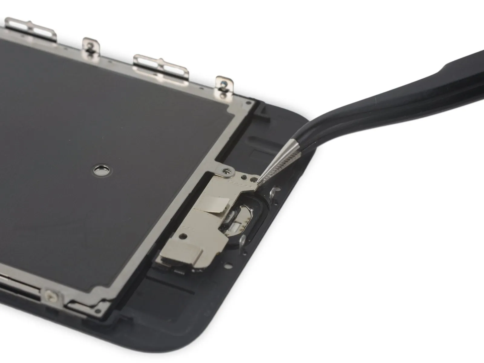
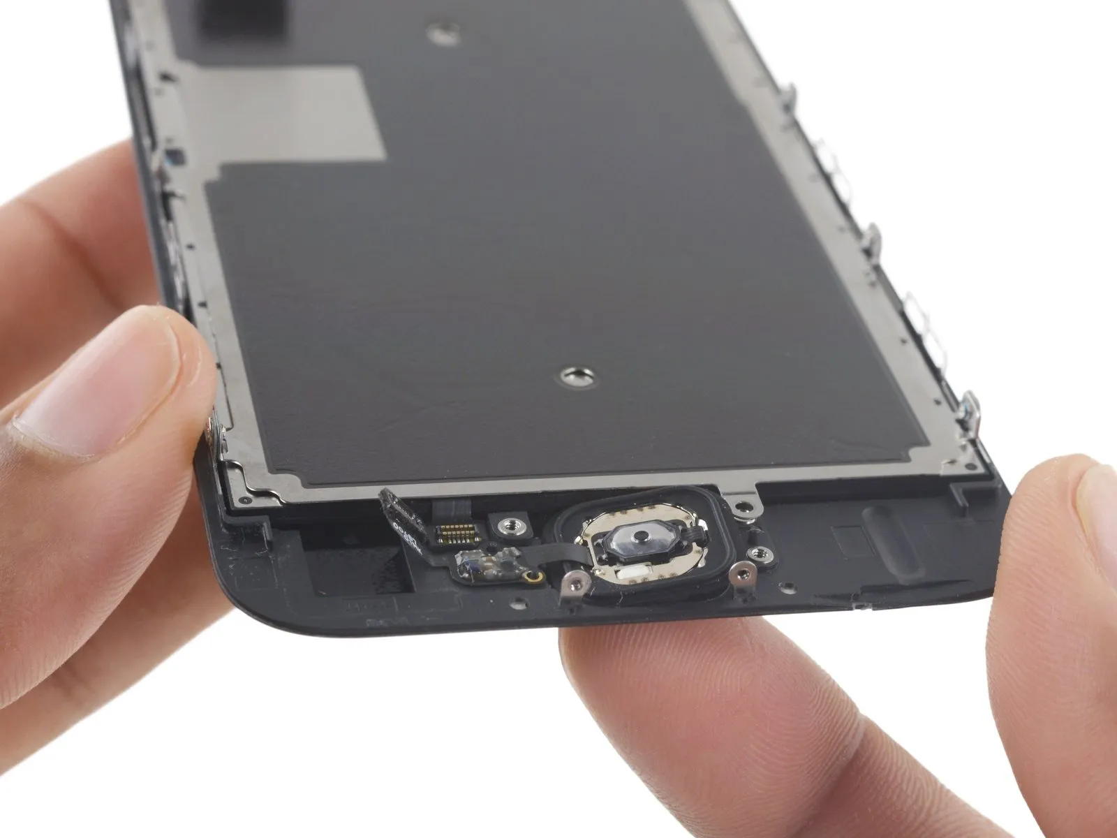
Step 26 | Home Button Assembly
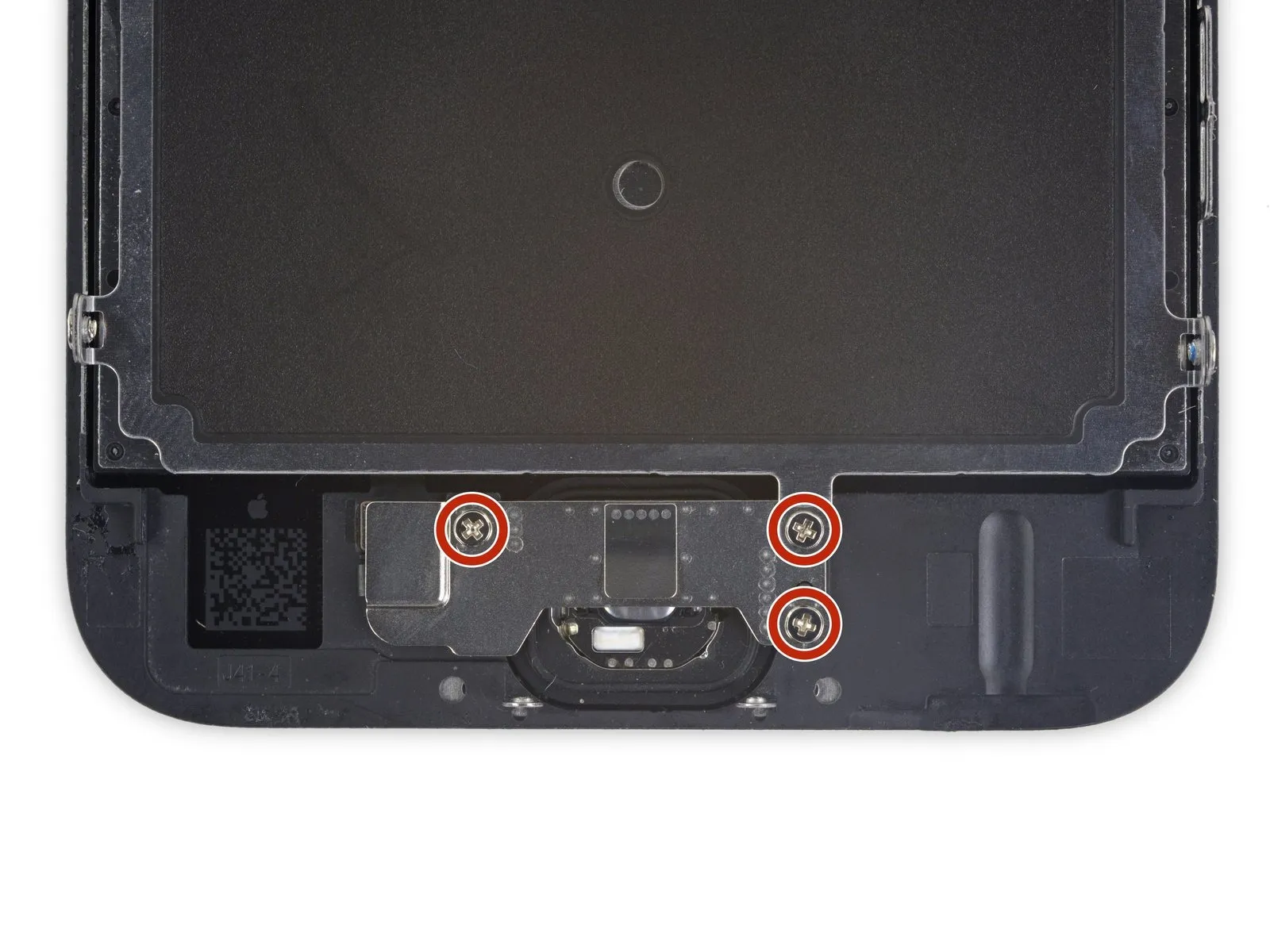
- Using the appropriate tool, detach the three screws.Use a Phillips screwdriver with a 1.7 mm tip.Using a Phillips #00 screwdriver, fasten the home button bracket with the provided screws, ensuring each is tightened to a torque of 1.2 Nm.
- To prevent damage to the display's front surface, ensure these screws are snug but not excessively tightened.
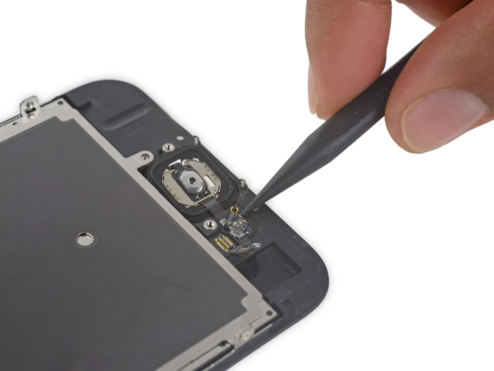
Step 27
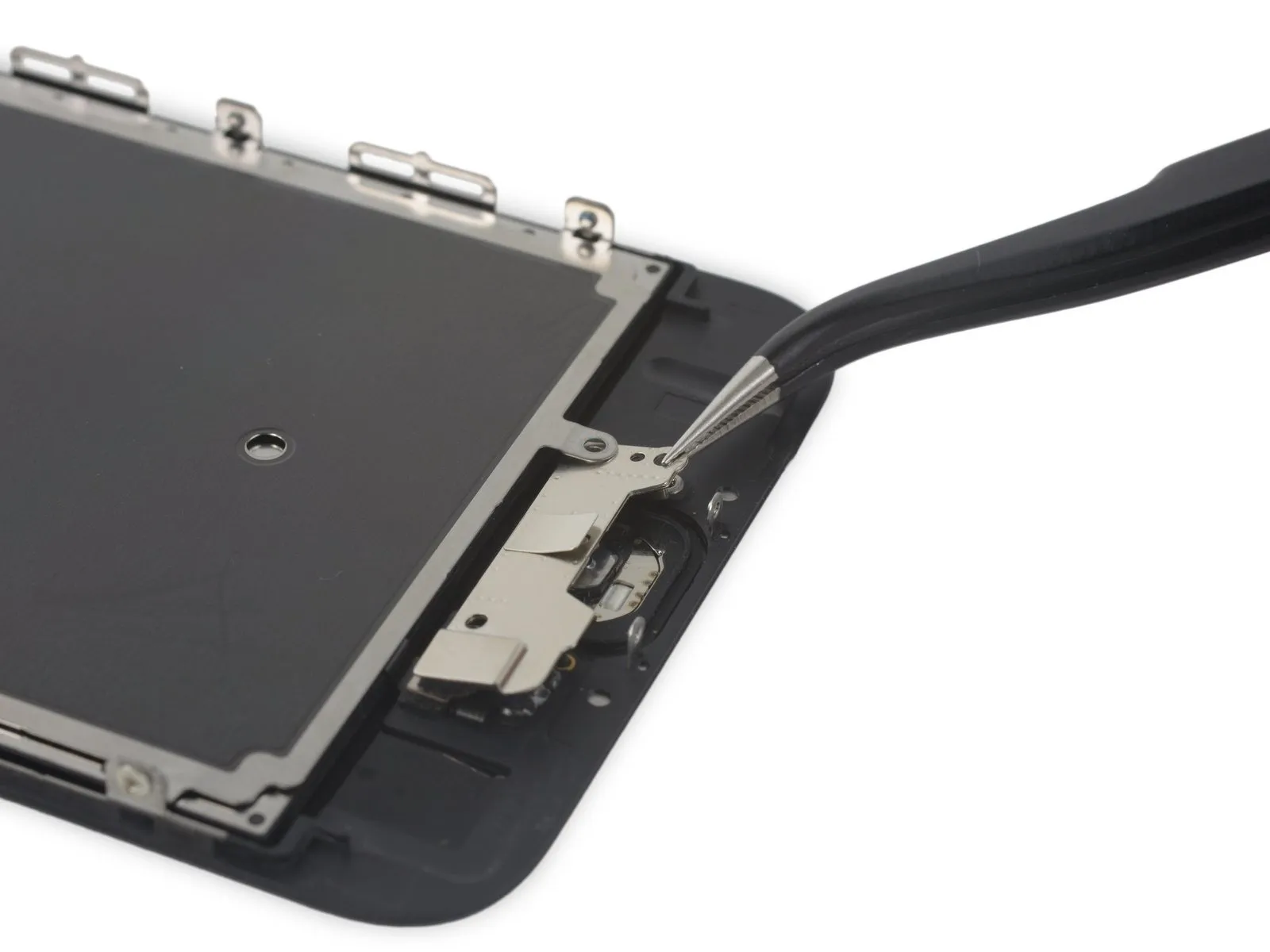
- Carefully raise the lower portion of the home button bracket, ensuring it disengages from the retaining pin located on the right-hand side.
- To detach the EMI shield, carefully disengage the bracket by moving it away from its position beneath the shield.
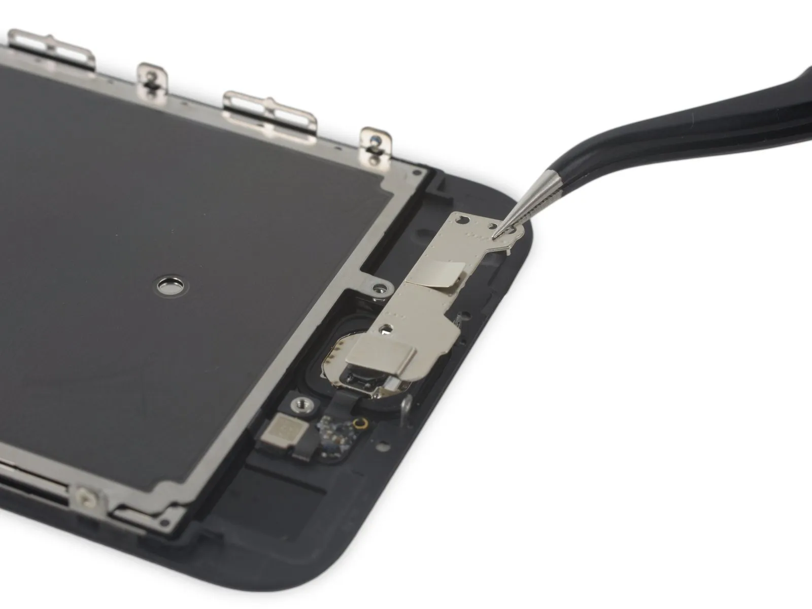
Step 28
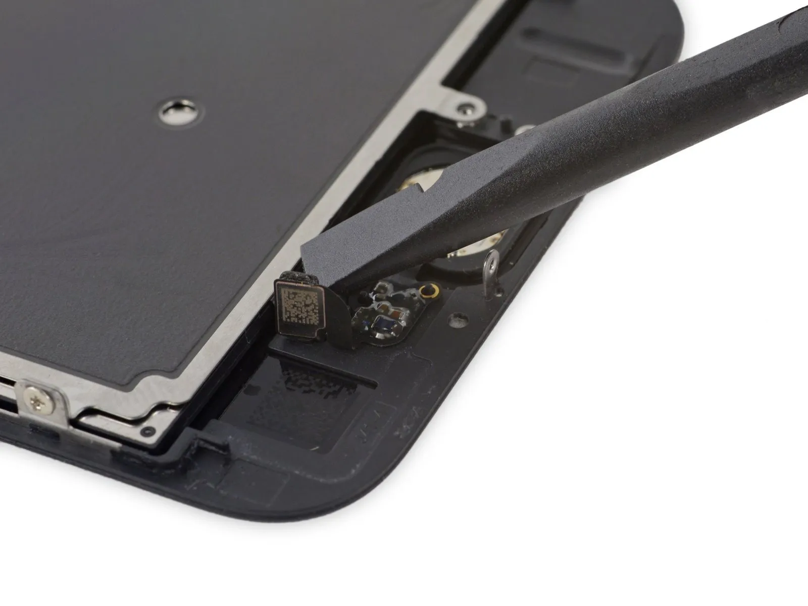
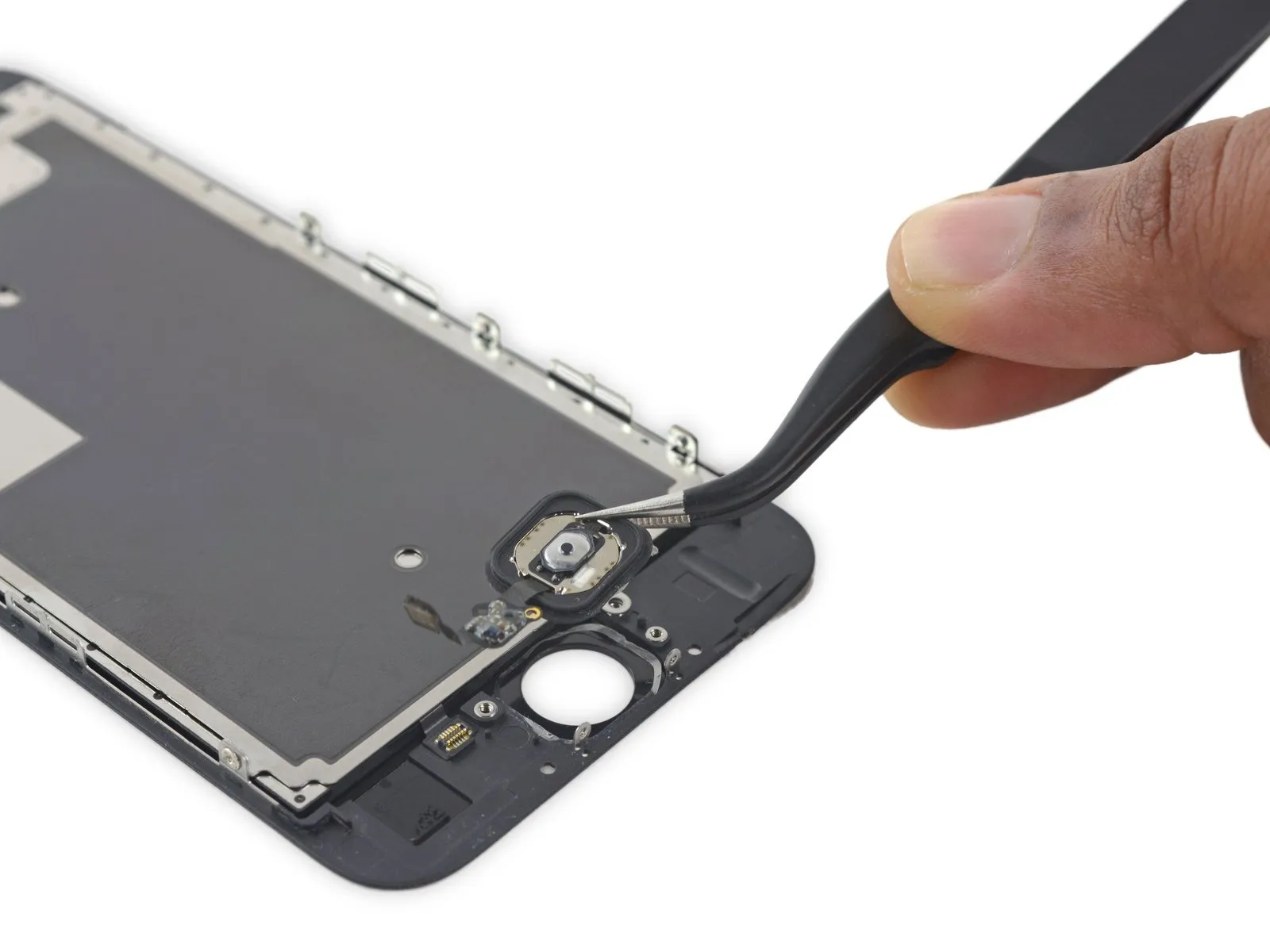
Carefully detach the home button connector from the rear of the display panel, employing a spudger to gently disengage it from its socket.
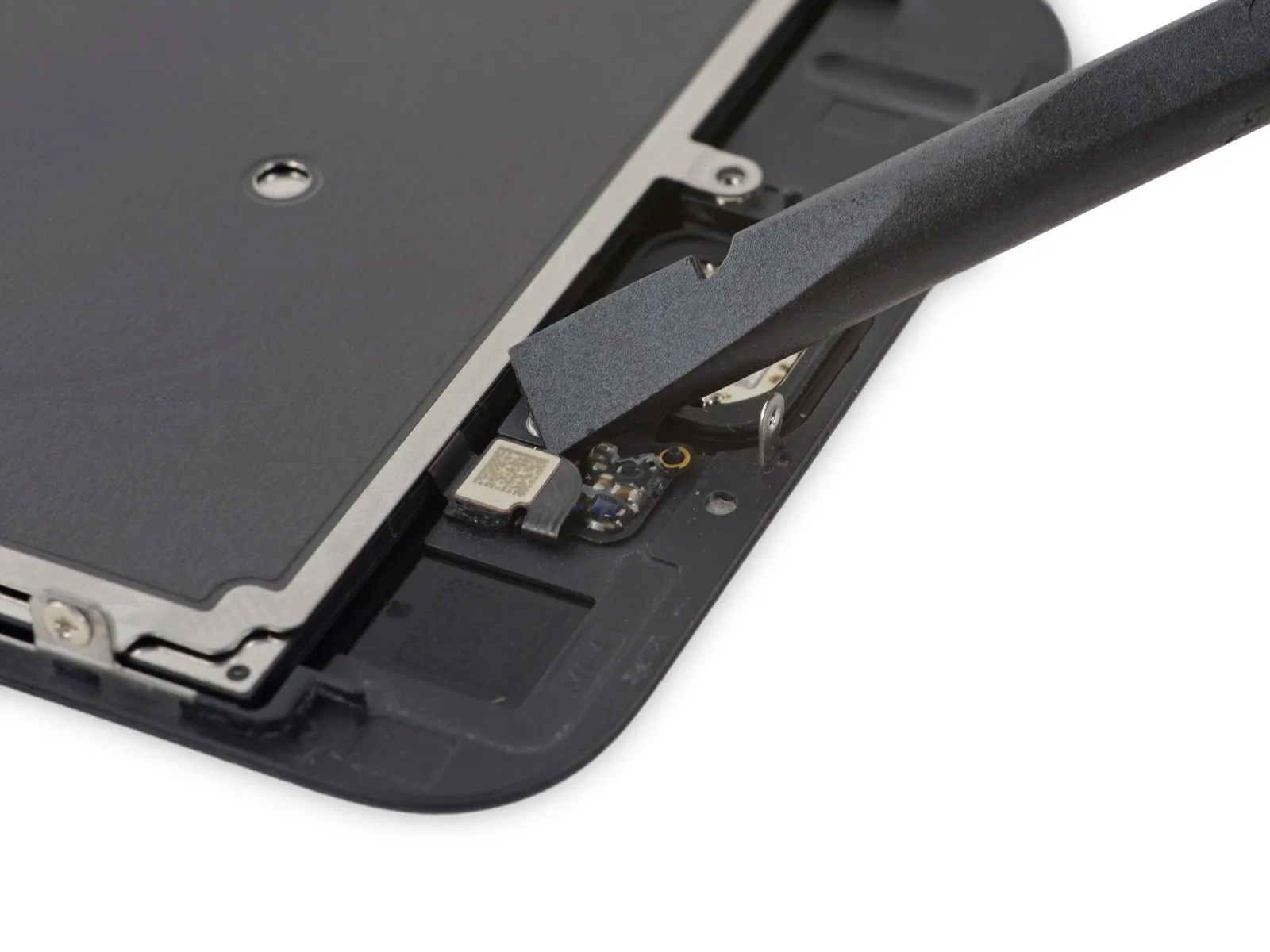
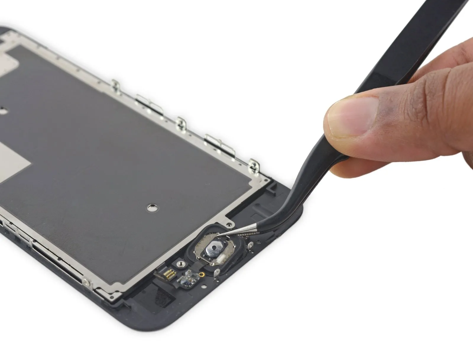
Step 29

- Due to its minimal thickness, the home button's rubber gasket is prone to tearing.
- Use a heat gun or hairdryer set to a low setting to gently warm the area.Use the iOpener to gently warm the adhesive securing the display assembly.,Apply heat using a tool that directs warm air, ensuring the temperature does not exceed 200°F (93°C).Using a 5/32-inch hex key, carefully loosen the retaining screw located on the motor shaft, ensuring to support the fan assembly to prevent damage, and then gently slide the motor off the shaft, paying attention to the 1.25-inch length of the shaft extension.Utilize a blow dryer to apply warm air, ensuring the temperature remains below 150°F (65°C), to soften the adhesive securing the component.Apply a solvent to loosen the adhesive that holds the home button gasket in place.
- Apply steady, upward force to the home button with your finger, originating from the display assembly's front surface, to carefully detach the rubber gasket surrounding the button from the front panel.
Step 30

- Gently detach the home button flex cable from the display panel's rear surface, utilizing the pointed end of a spudger.
Step 31
Step 32 | Screen