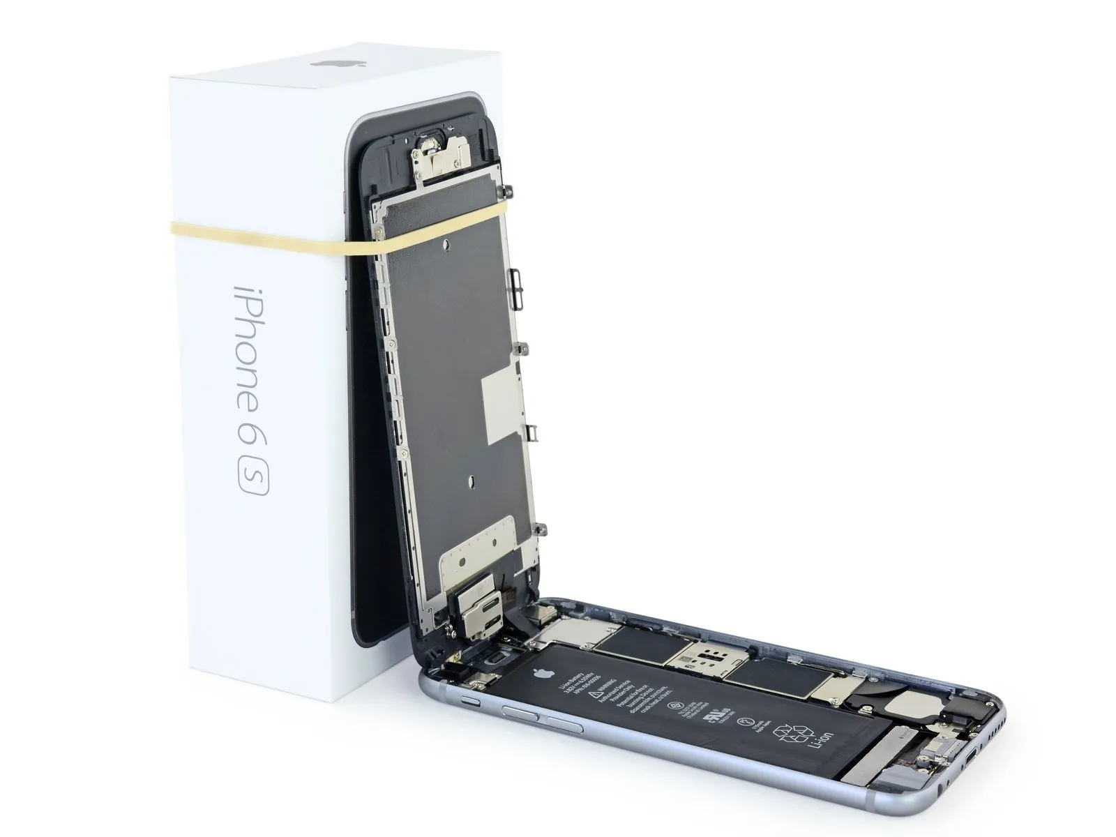
iPhone 6s Volume Control Button Covers Replacement
This document details the procedure for physically removing and substituting the volume button covers on an iPhone 6s; it addresses only the external button components and excludes the underlying electronic mechanisms.
- To substitute the volume control cable or associated electronic components, consult an alternate repair procedure.
Step 1 | Pentalobe Screws
To prevent a fire or explosion hazard from a potentially damaged lithium-ion battery, ensure its charge level is less than 25% prior to beginning any disassembly procedures on your iPhone.
To prevent electrical shock or damage to components, ensure the iPhone is completely de-energized prior to starting the repair process.
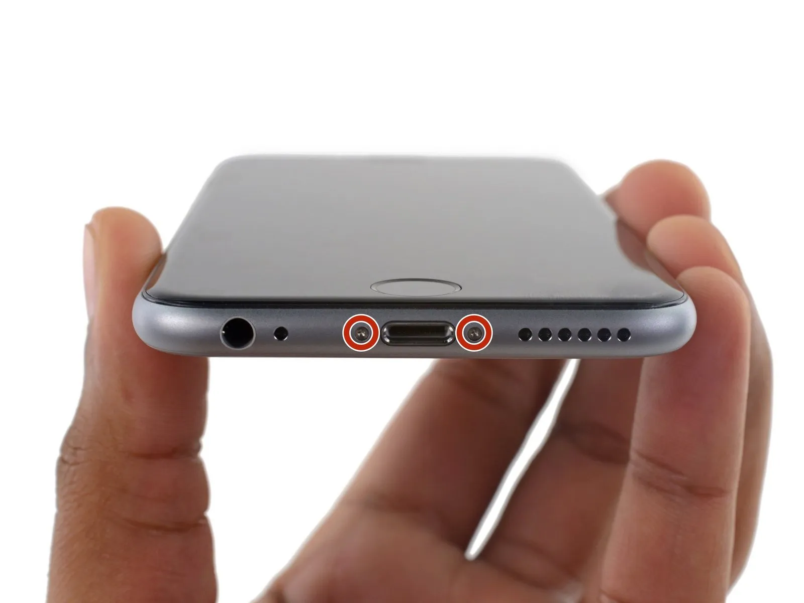
Using a Pentalobe screwdriver compatible with 3.4 mm screws, detach the two screws located on the lower edge of the device, one on each side of the Lightning connector.
To prevent electrical shock or damage to components, ensure the iPhone is completely de-energized prior to starting the repair process.
Using a Pentalobe screwdriver compatible with 3.4 mm screws, detach the two screws located on the lower edge of the device, one on each side of the Lightning connector.
Step 2 | Anti-Clamp instructions


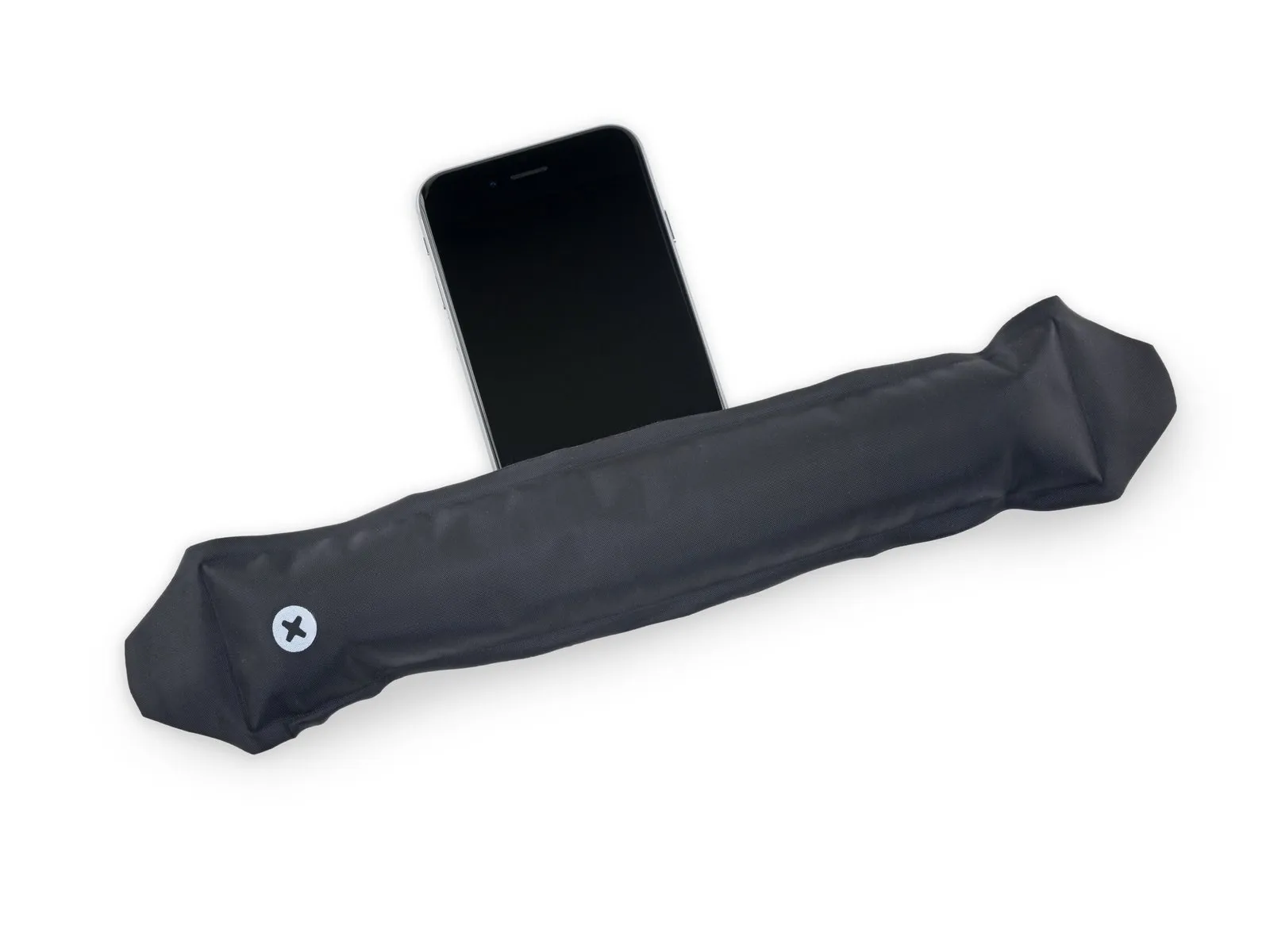
To simplify the opening process, the following two steps utilize the Anti-Clamp tool, a custom-designed aid; if you do not have this tool, proceed to the steps three sections later for an alternative approach.
Refer to the included guide for detailed procedures regarding Anti-Clamp operation.
To release the Anti-Clamp's arms, move the blue handle in a rearward direction.
Position the arms so they extend across the iPhone's left or right side.
Carefully place a suction cup on the front surface of the iPhone, close to the lower edge and directly over the home button, and another suction cup on the rear surface, in a similar location.
Apply vacuum by pressing the cups firmly against the surface needing treatment.
To improve the Anti-Clamp's grip if the iPhone's exterior feels excessively smooth, apply adhesive tape to the device's surface.
Step 3


To secure the arms, advance the blue handle in the direction indicated.
Rotate the handle fully, completing a 360-degree turn, observing for the initial expansion of the cups.
Maintain parallel positioning of the suction cups; should misalignment occur, gently release the suction cups' grip and reposition the arms.
Once sufficient space is created by the Anti-Clamp, slide a separating tool beneath the display.
To ensure adequate clearance, reposition the handle by 90 degrees.
Allow the Anti-Clamp device to function, pausing for several seconds and limiting each incremental rotation to a maximum of 90 degrees to ensure proper seating.
Step 4 | Opening Procedure
Lacking an Anti-Clamp tool, proceed with the subsequent three steps to utilize a suction handle.
Using a hair dryer or iOpener, gently warm the iPhone's bottom perimeter with moderate heat for approximately one minute.
Applying heat will loosen the adhesive that holds the display in place, facilitating separation.
Using a hair dryer or iOpener, gently warm the iPhone's bottom perimeter with moderate heat for approximately one minute.
Applying heat will loosen the adhesive that holds the display in place, facilitating separation.
Step 5
To access the 6s display, carefully release the adhesive strip that runs along its edges; replacement adhesive strips should be available if you intend to use them. Functionality remains unaffected whether the adhesive is replaced or not.
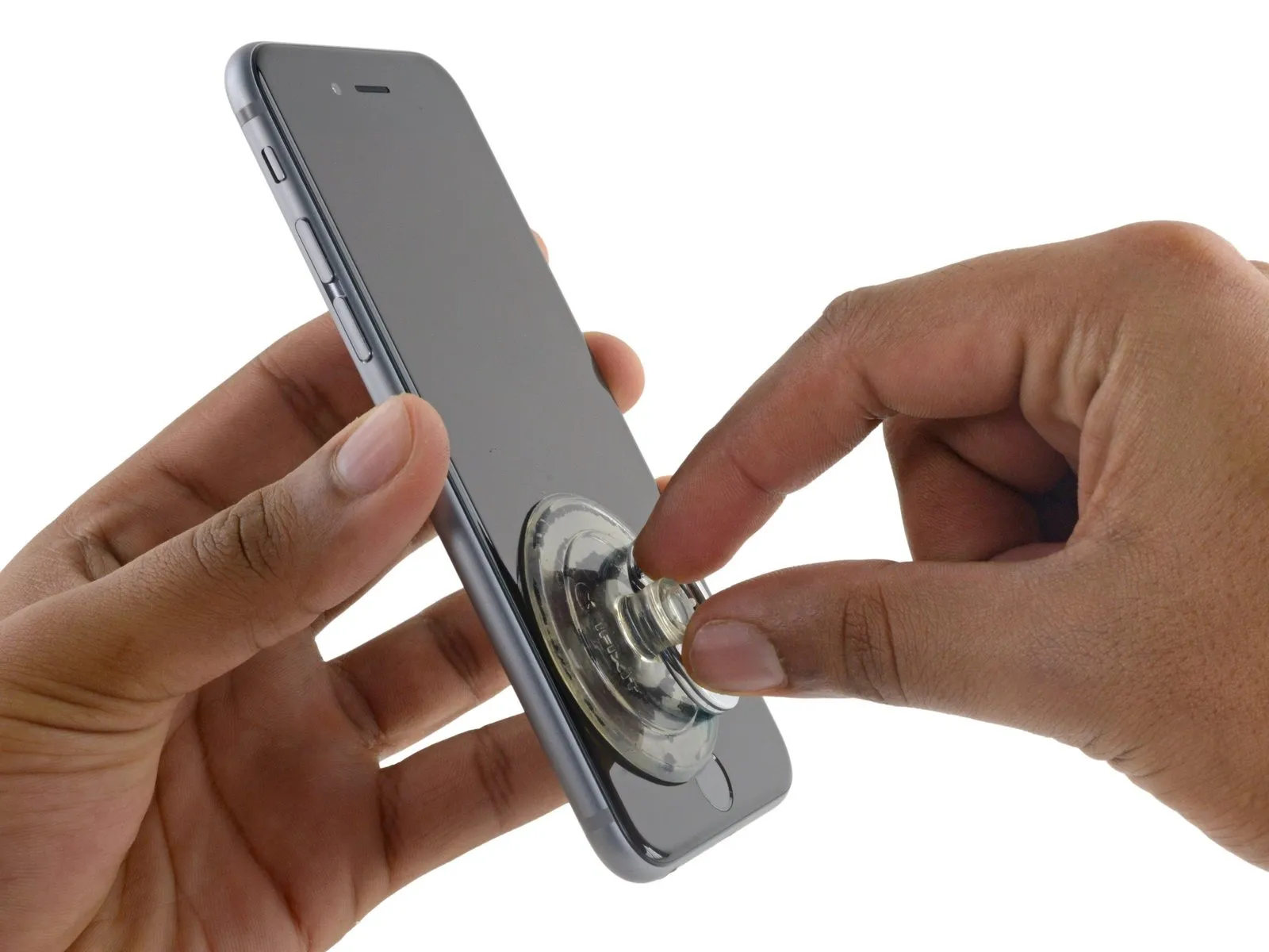
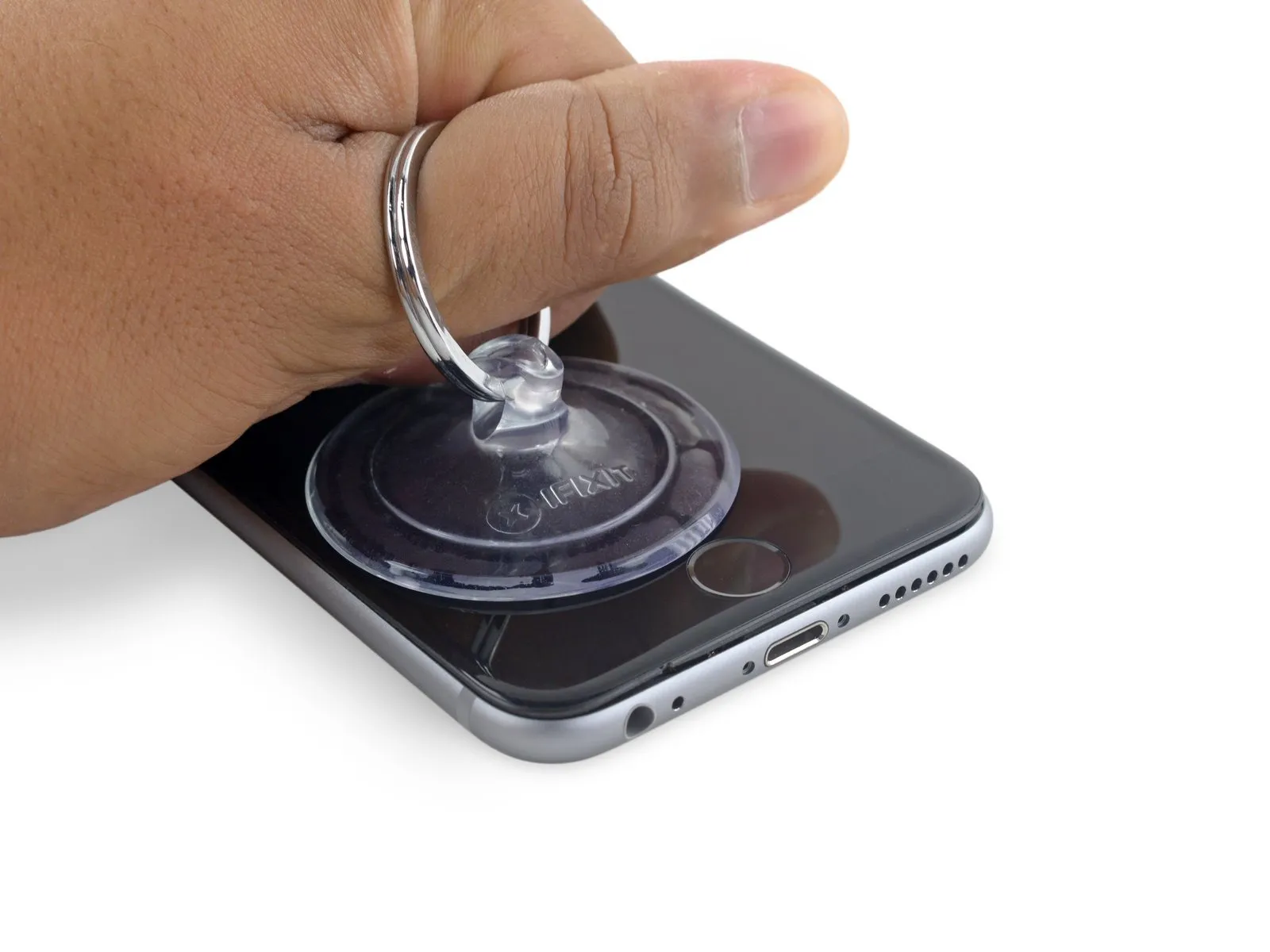
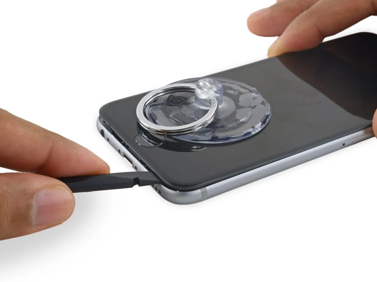
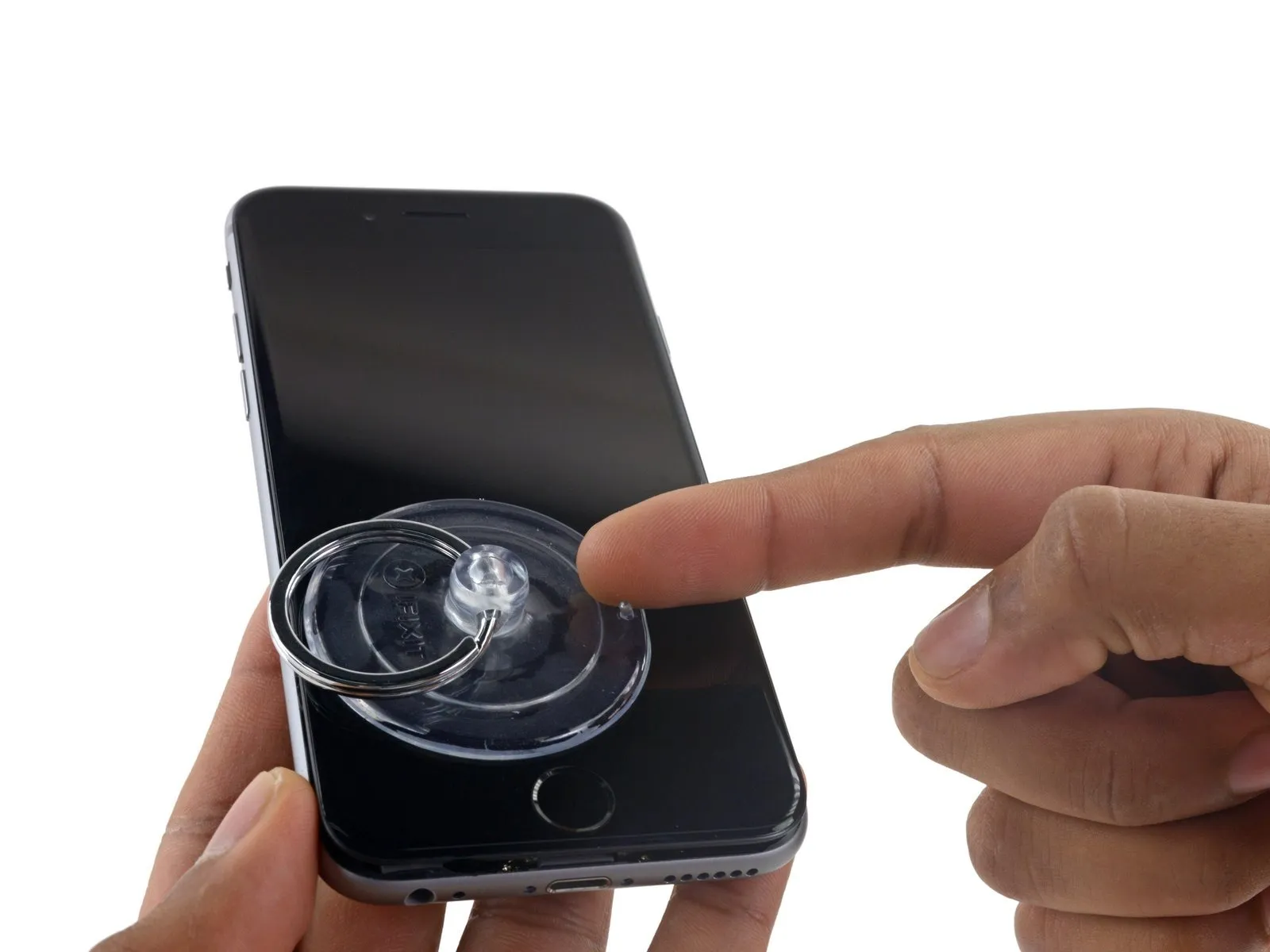
Using a suction cup, secure its surface to the display assembly's lower-left corner.
Avoid positioning the suction cup directly on the home button.
To facilitate suction cup attachment on a severely cracked display, apply a sheet of clear packing tape across the damage; as an alternative, a robust adhesive tape can be used directly. Should these methods prove ineffective, secure the suction cup to the screen using superglue as a last resort.
Step 6
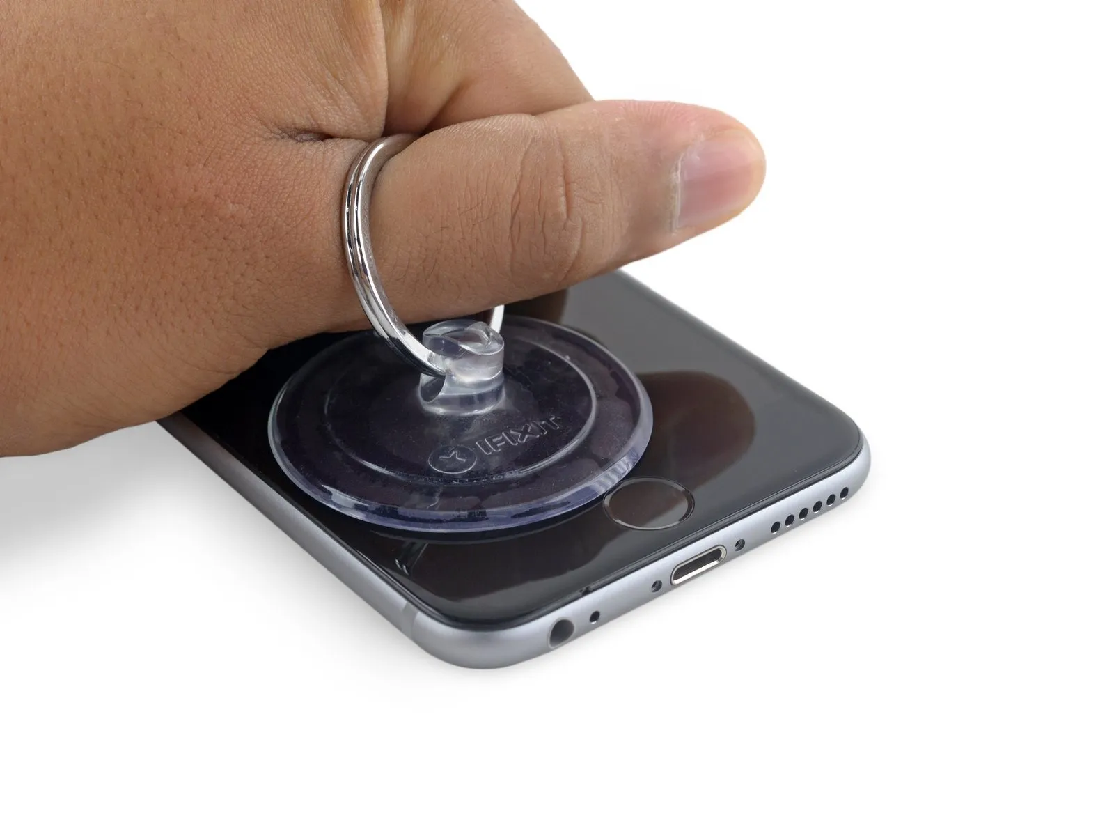
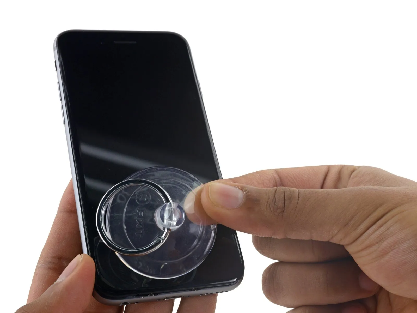
Carefully align the 4mm diameter dowel pin with the corresponding hole in the chassis and gently press it into place, ensuring it is fully seated to prevent loosening during operation; observe caution to avoid damaging the surrounding plastic components.Apply steady, even force to lift the suction cup, generating a small separation between the front panel and the rear case.
Exercise caution and use steady, even pressure when installing the display assembly, as it requires a snug fit and is secured with adhesive.
To avoid display assembly damage, use minimal force when separating components; the goal is to generate a slight space between the display assembly and the rear case.
To ease separation of the display adhesive, apply heat to the iPhone's front surface with an iOpener, hair dryer, or heat gun until the area reaches a temperature just beyond comfortable touch.
Step 7
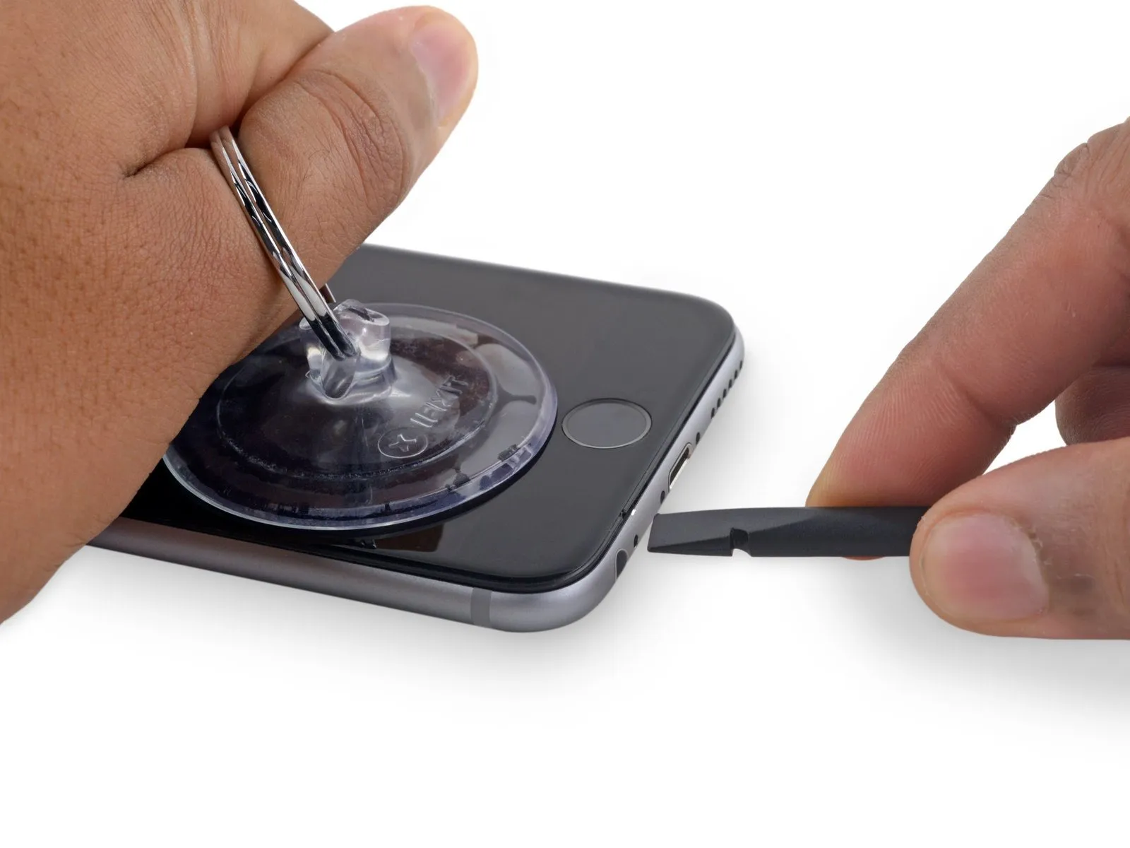
Using a 5/32-inch hex key, carefully tighten the four mounting screws securing the fan assembly to the motor housing, ensuring each is snug but not over-tightened to prevent damage; observe a torque of 6 in-lbs per screw.To initiate separation of the device's housing, insert a plastic opening tool into the recessed area located on the bottom surface of the display, positioned directly over the headphone jack; this area provides the most secure starting point to prevent damage.
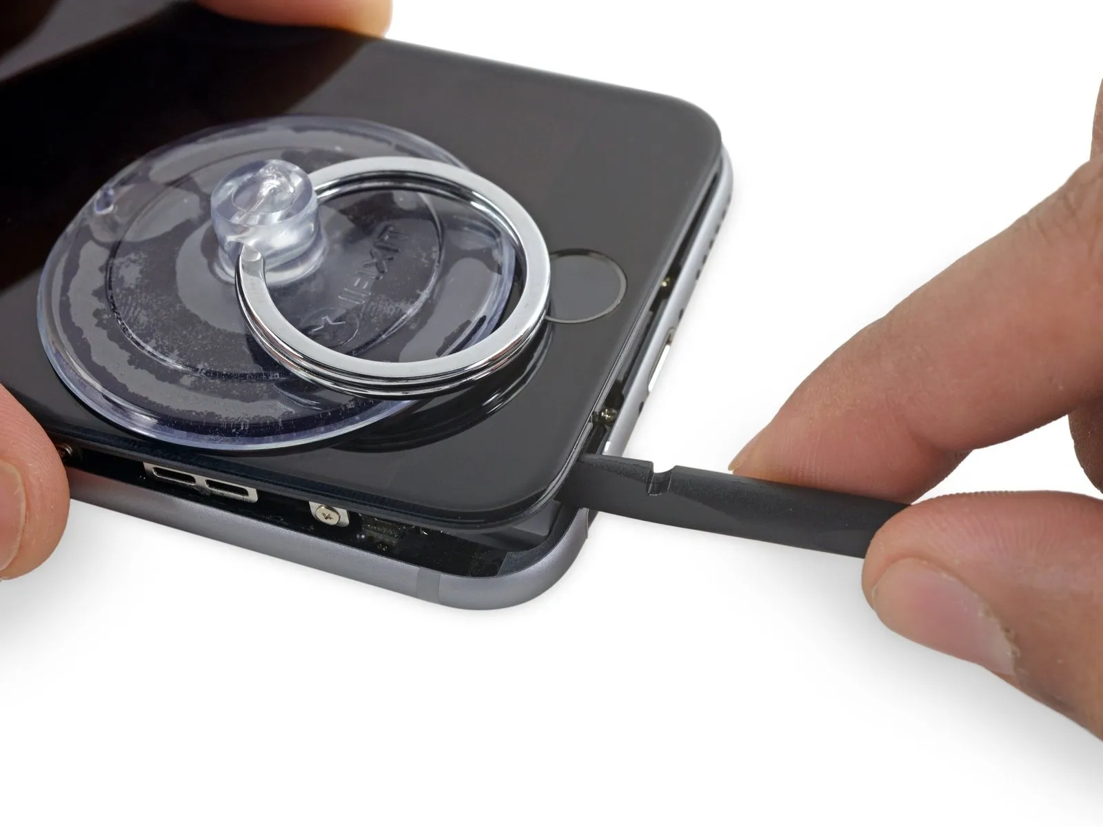
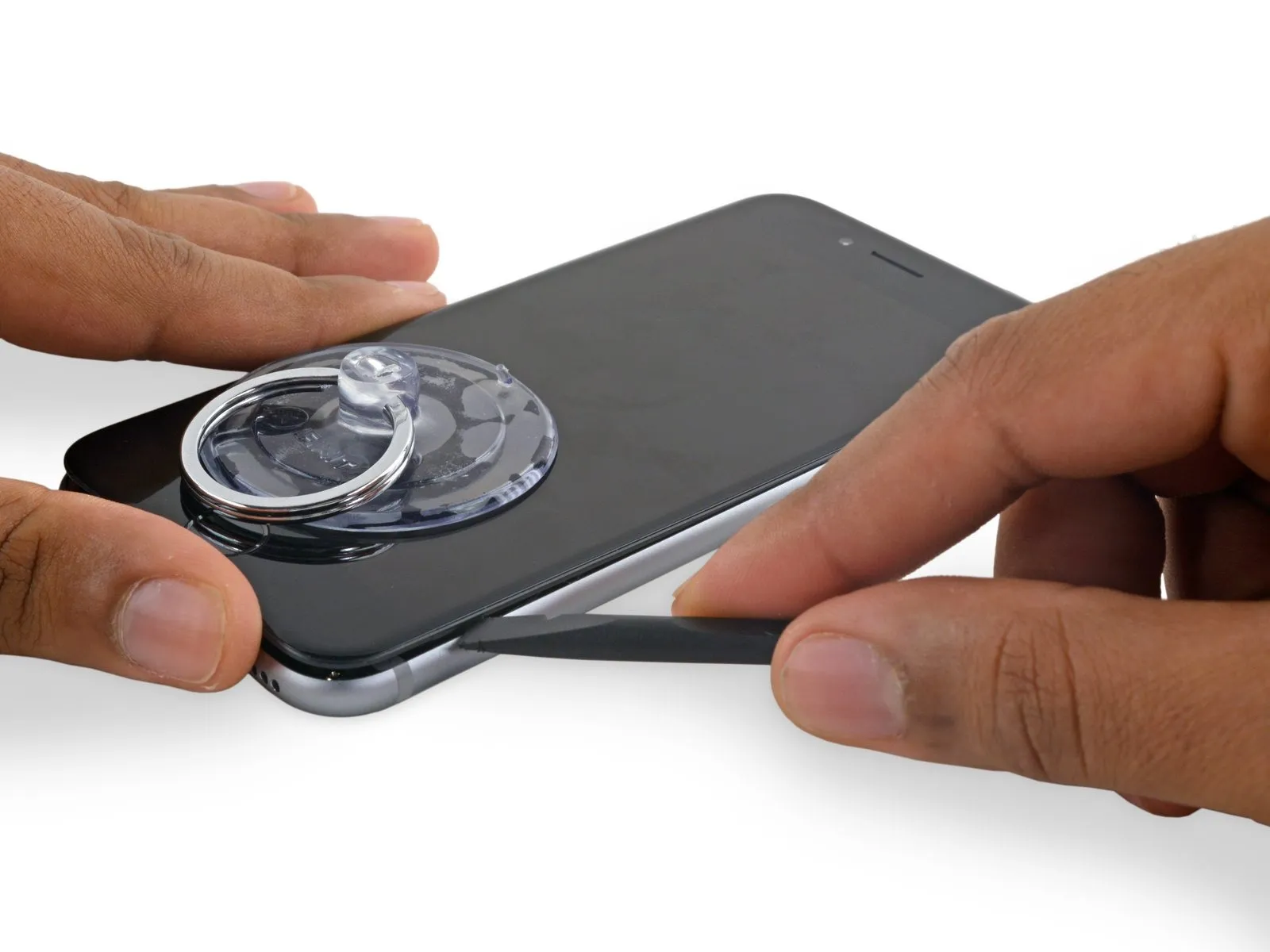
Using a spudger, insert its flat side into the separation between the display and the back cover, positioning the insertion point immediately over the headphone jack.
Using a spudger, insert its flat side into the separation between the display and the back cover, positioning the insertion point immediately over the headphone jack.
Step 8
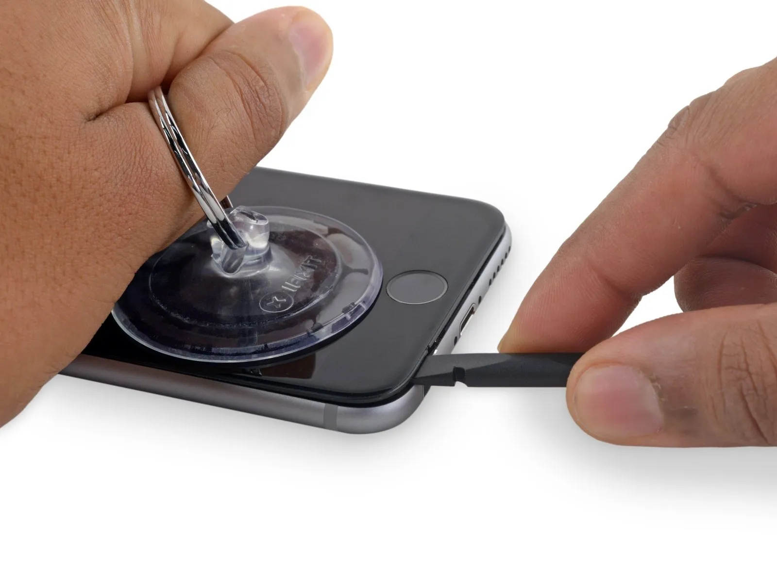
Using a 5/32-inch hex key, carefully tighten the four mounting screws securing the fan assembly to the motor housing, ensuring each is snug but not over-tightened to prevent damage; observe a torque of 6 in-lbs per screw.Using the spudger, gently increase the separation between the front panel assembly and the phone's main body by applying rotational force.
Step 9
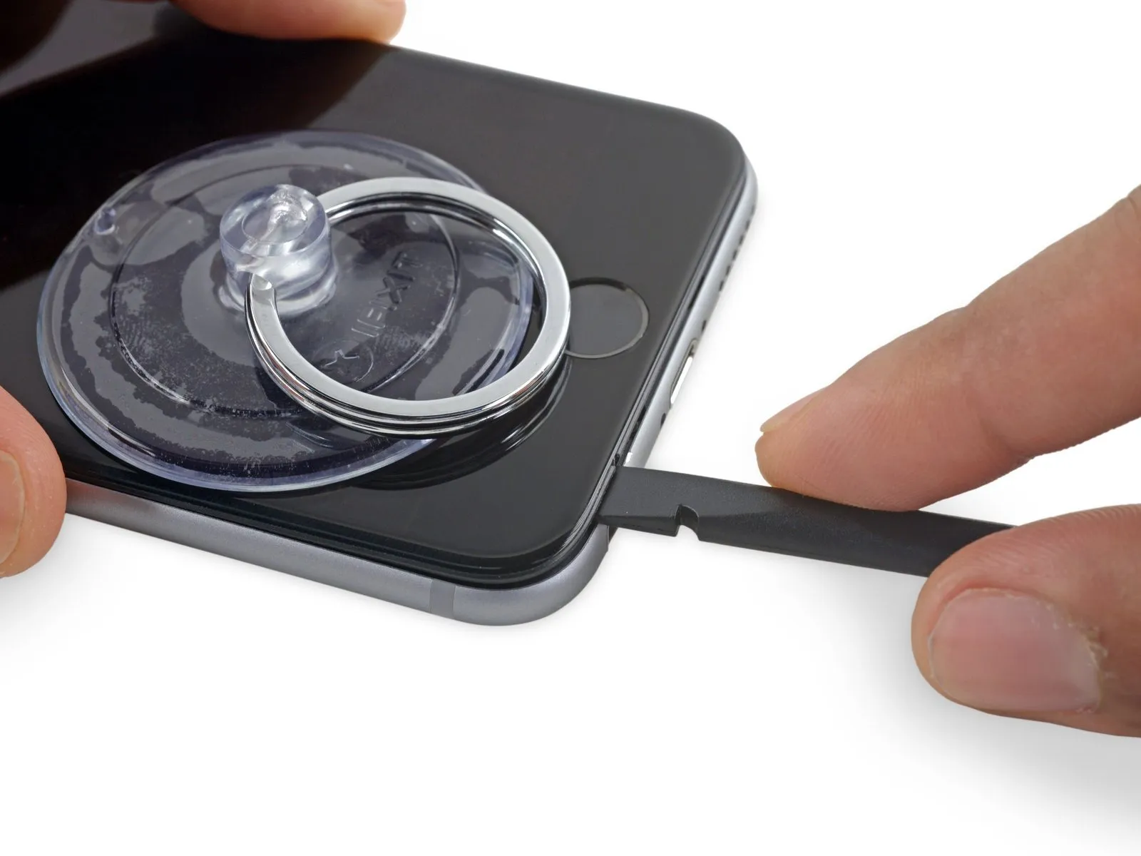
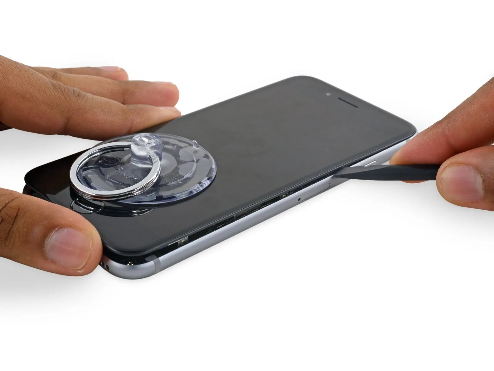
Using a 5/32-inch hex key, carefully tighten the three retaining screws on the motor assembly to a torque of 3.5 inch-pounds, ensuring no damage occurs to the threads; failure to adhere to this torque specification could result in premature motor failure.Using a spudger, carefully slide the flat tip into the gap located on the left-hand side of the device, separating the display assembly from the rear case.
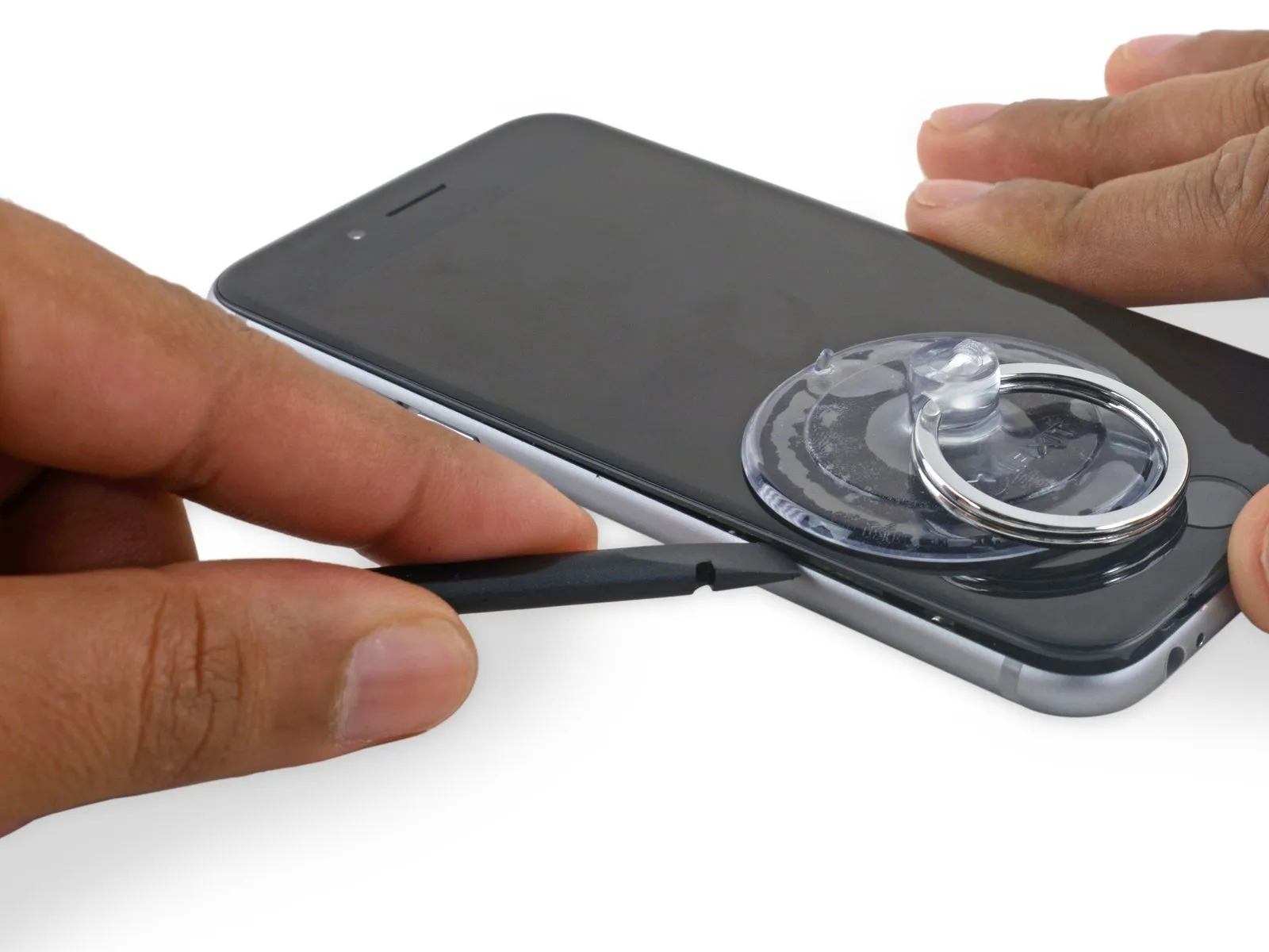
Using a spudger, carefully insert it between the phone's side edge and the chassis to release the adhesive bond and disengage the retaining clips.
Using a spudger, carefully insert it between the phone's side edge and the chassis to release the adhesive bond and disengage the retaining clips.
Step 10
Using a torque wrench, secure the crankshaft pulley with a fastening torque of 170 Nm (125 lb-ft), ensuring the pulley is properly aligned with the crankshaft.Using the spudger, carefully re-engage it along the lower edge of the device, the area previously separated.
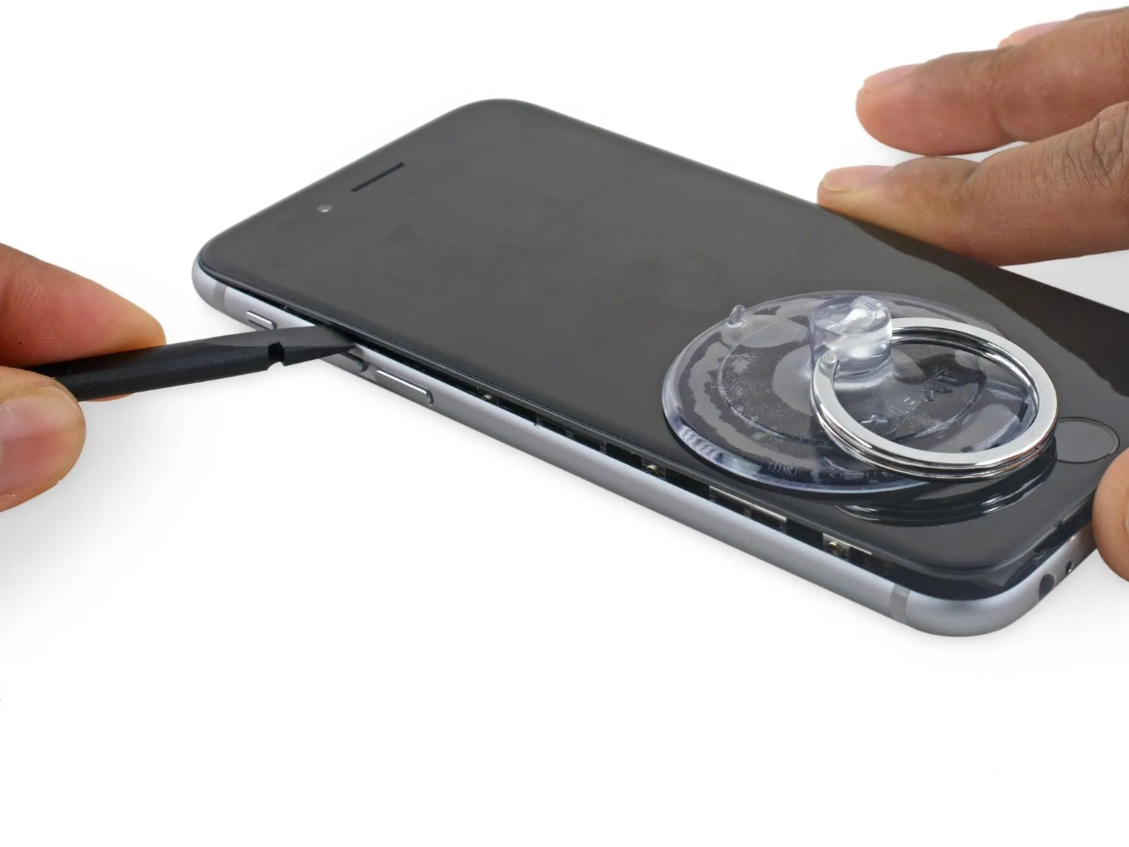
Using a spudger, gently move it horizontally across the phone's lower border.
Using a spudger, gently move it horizontally across the phone's lower border.
Step 11
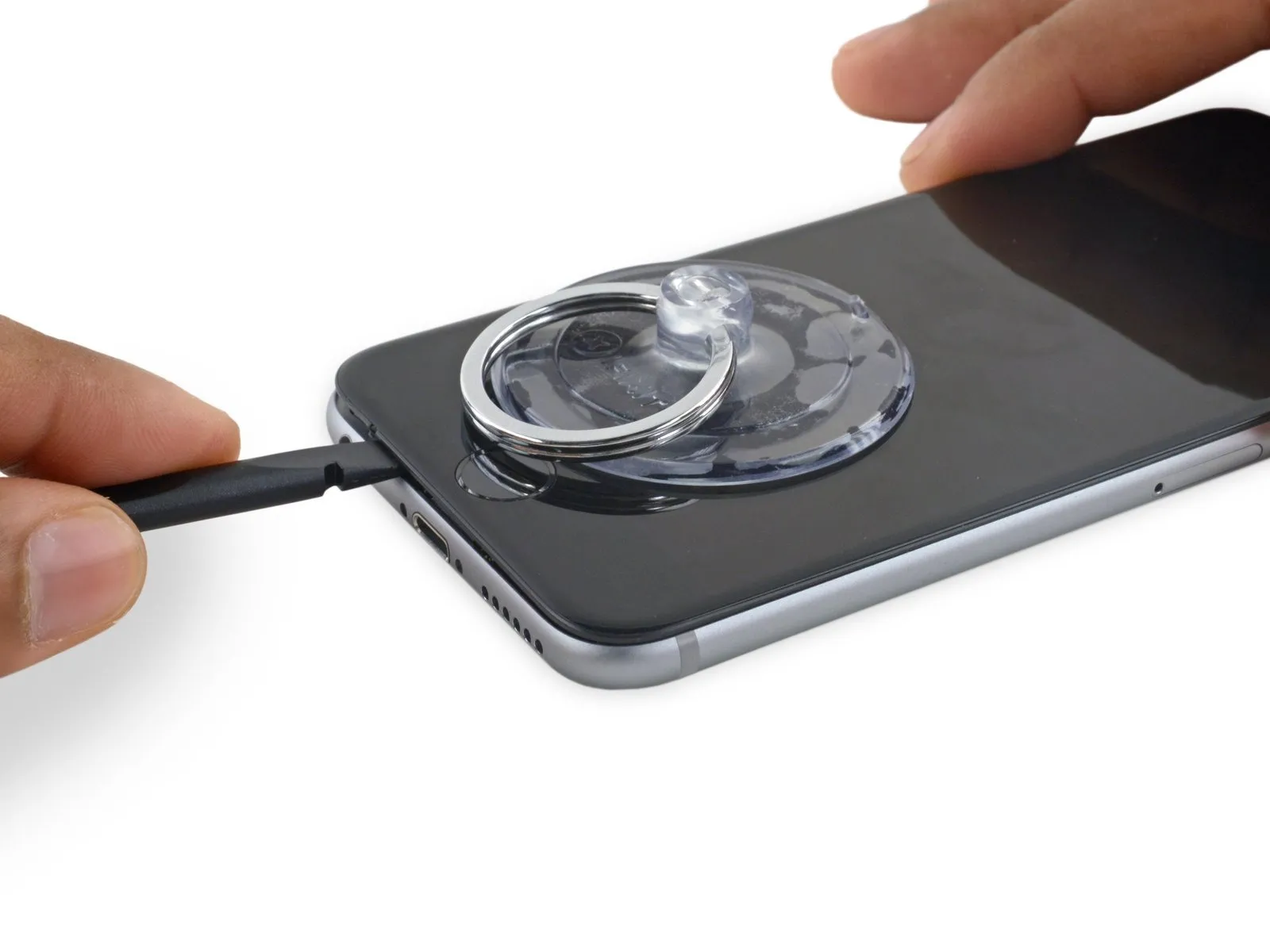
Using a spudger, carefully work along the right edge to release the adhesive bond and disengage the display clips securing the iPhone.
Step 12

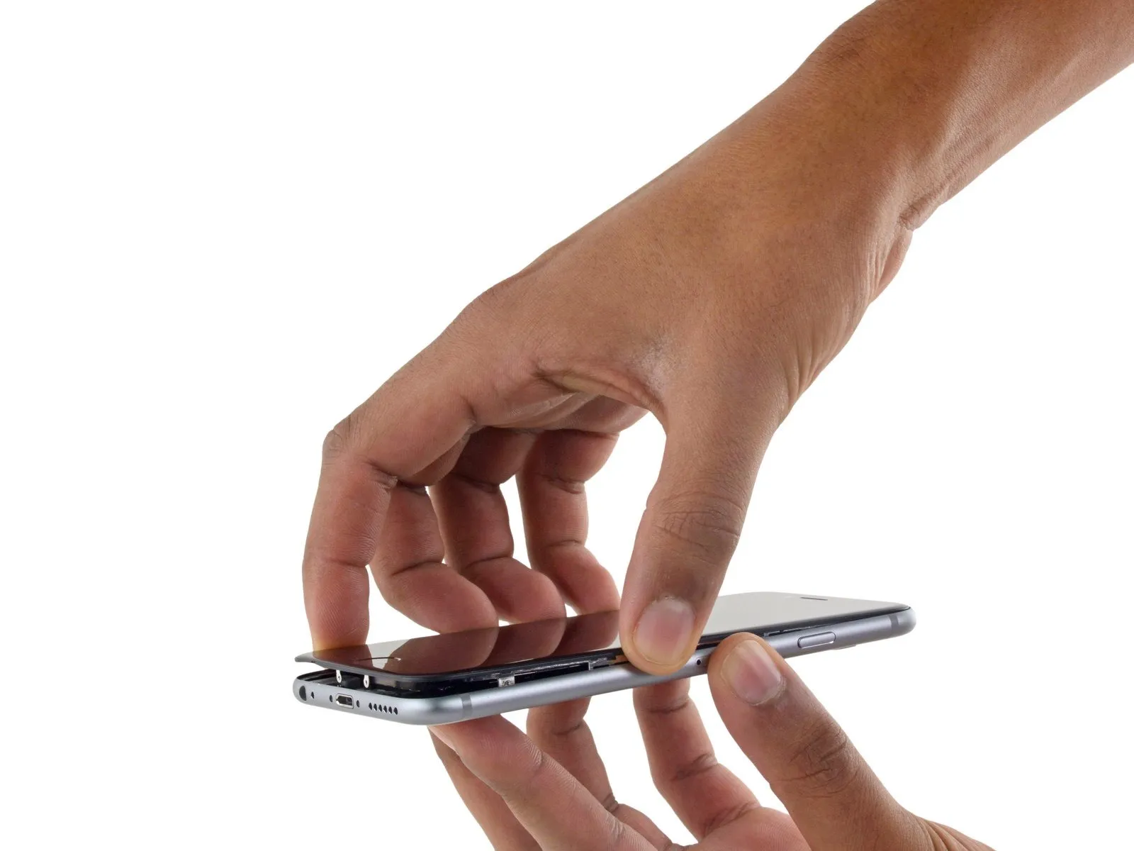
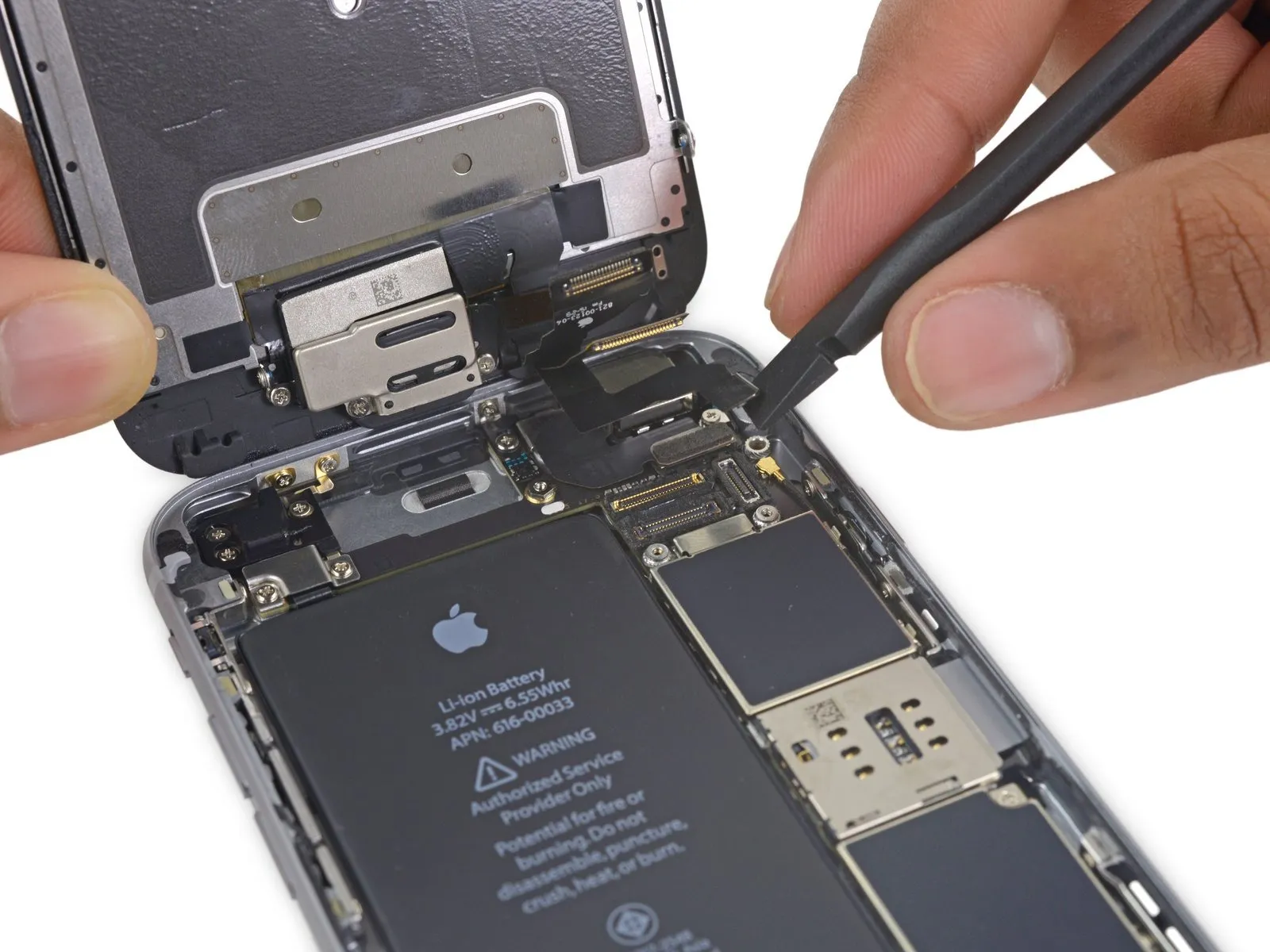
Carefully leverage the suction cup to separate the display assembly, ensuring complete release of the remaining adhesive bond.
To prevent damage, limit the display's opening angle to a maximum of 90 degrees; the three cables connecting it to the top edge are susceptible to breakage if pulled taut.
To prevent damage, limit the display's opening angle to a maximum of 90 degrees; the three cables connecting it to the top edge are susceptible to breakage if pulled taut.
Step 13
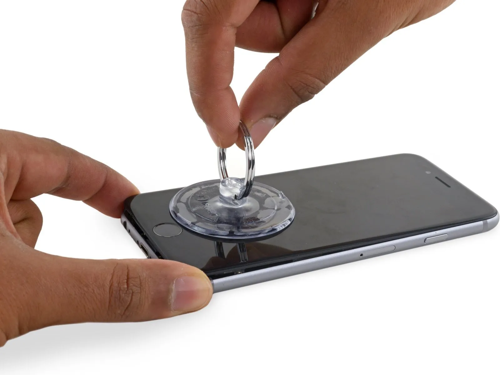
To detach the suction cup, grasp the small projection located on its upper surface and lift, separating it from the front panel.
Step 14
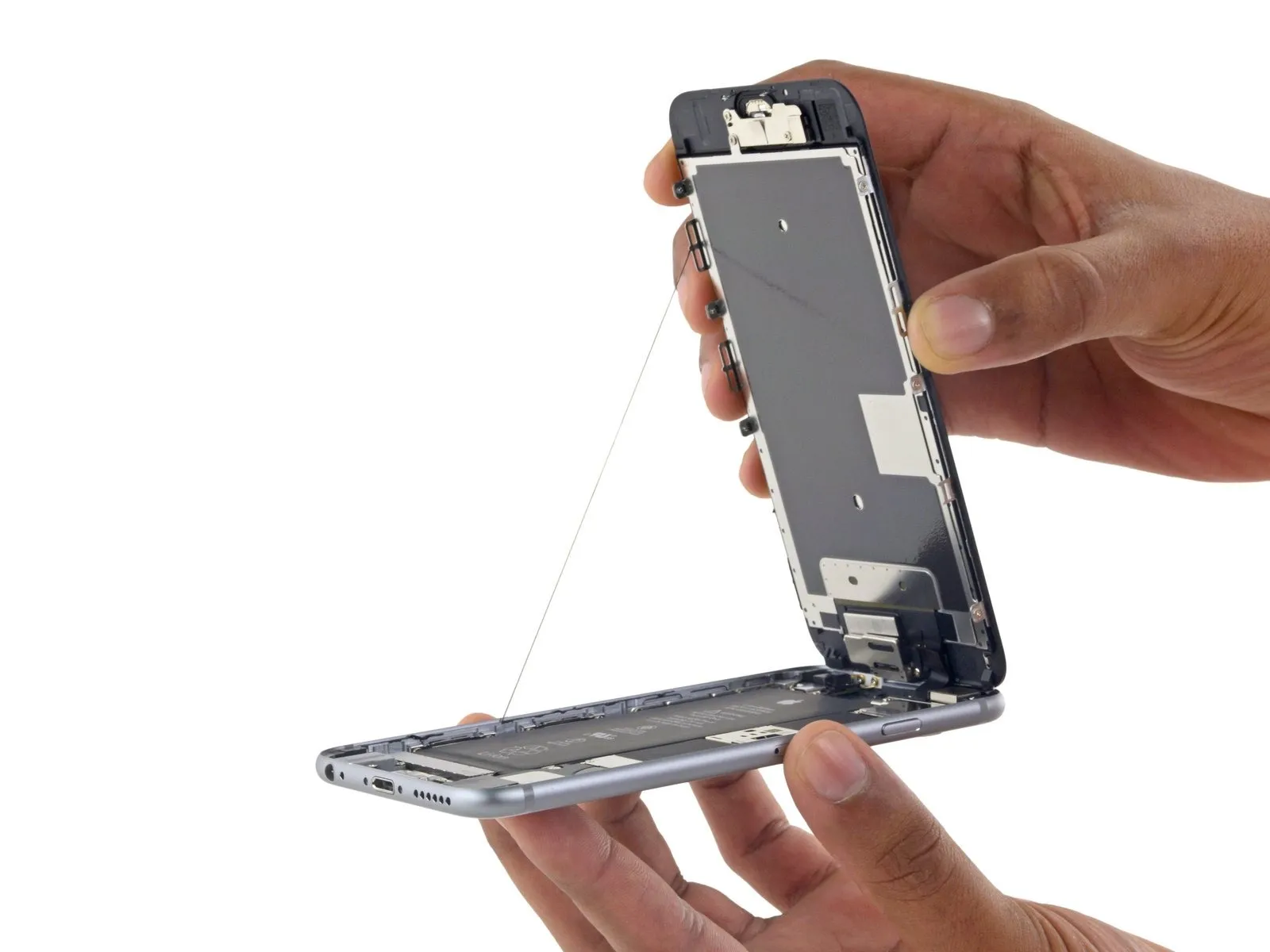
Using the top edge's retaining clips as a pivot point, carefully raise the display assembly to separate the front panel and access the phone's interior.
Carefully position the display at a roughly 90-degree angle, then secure it in an upright position using a support to prevent movement during the repair process.
To avoid stressing the display's wiring during the repair process, secure it with a rubber band.
As a temporary substitute, an unopened, standard-sized canned drink can provide the necessary support for the display during this procedure.
If you intend to substitute fresh adhesive along the display's perimeter during reassembly, stop at this point.
To ensure proper alignment during reassembly, guide the camera-side edge of the screen body beneath the main body's edge. Position the screen frame's hooks beneath the main body's rim, then gently push them towards the camera end to facilitate cover closure and secure clipping.
Ensure these clasps are positioned beneath the phone's outer rim, as they function as a securing mechanism rather than a traditional hinge; this placement allows the screen to smoothly and quietly return to its closed position, engaging with a gentle snap.
To reinstall the screen, begin by applying pressure along the top right corner, working downwards, then repeat the process on the left side.
Step 15 | Battery Connector
Using a Phillips screwdriver, detach the two screws—each measuring the same length—that hold the battery connector bracket in place.
Utilize a 2.9 mm screw for this step.
Utilize a 2.2-millimeter screw for installation.
To prevent damage to your iPhone during this repair, carefully organize and return each screw to its original location, noting its specific placement.
Utilize a 2.9 mm screw for this step.
Utilize a 2.2-millimeter screw for installation.
To prevent damage to your iPhone during this repair, carefully organize and return each screw to its original location, noting its specific placement.
Step 16
Using a 5mm hex screwdriver, detach the bracket securing the battery connector.
Step 17

Carefully separate the battery connector from the logic board by applying upward pressure with a spudger.
Step 18
To prevent unintended power-ups during the repair process, carefully detach the battery connector from its socket on the logic board, ensuring it remains disconnected.
Step 19 | Unfasten the display cable bracket
Using a Phillips screwdriver, detach the four screws that fasten the display cable bracket in place.
Use three screws, each measuring 1.2 millimeters.
A screw with a 2.8 mm diameter is required.
Use three screws, each measuring 1.2 millimeters.
A screw with a 2.8 mm diameter is required.
Step 20
Using a T4 Torx screwdriver, detach the bracket securing the display cable.
Step 21
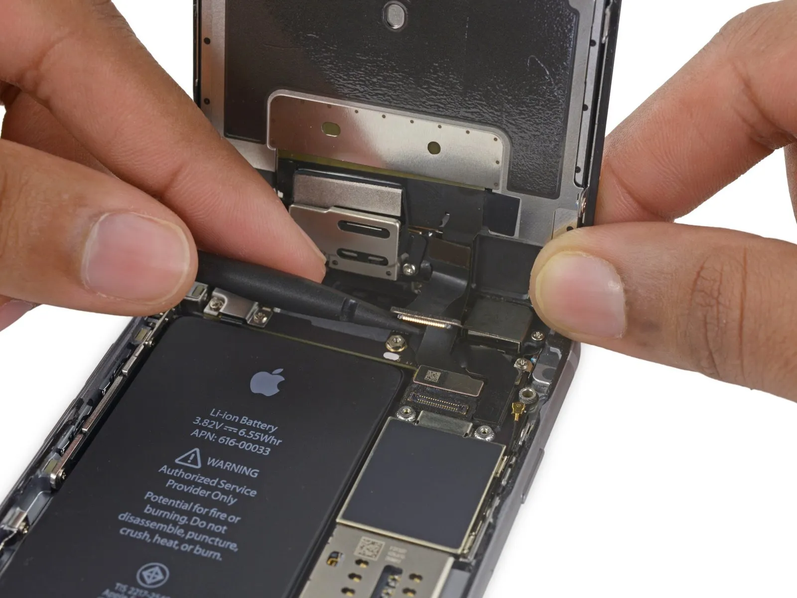
Carefully separate the front camera flex cable from its connector on the logic board by applying upward pressure with a spudger or a clean fingernail.
Step 22
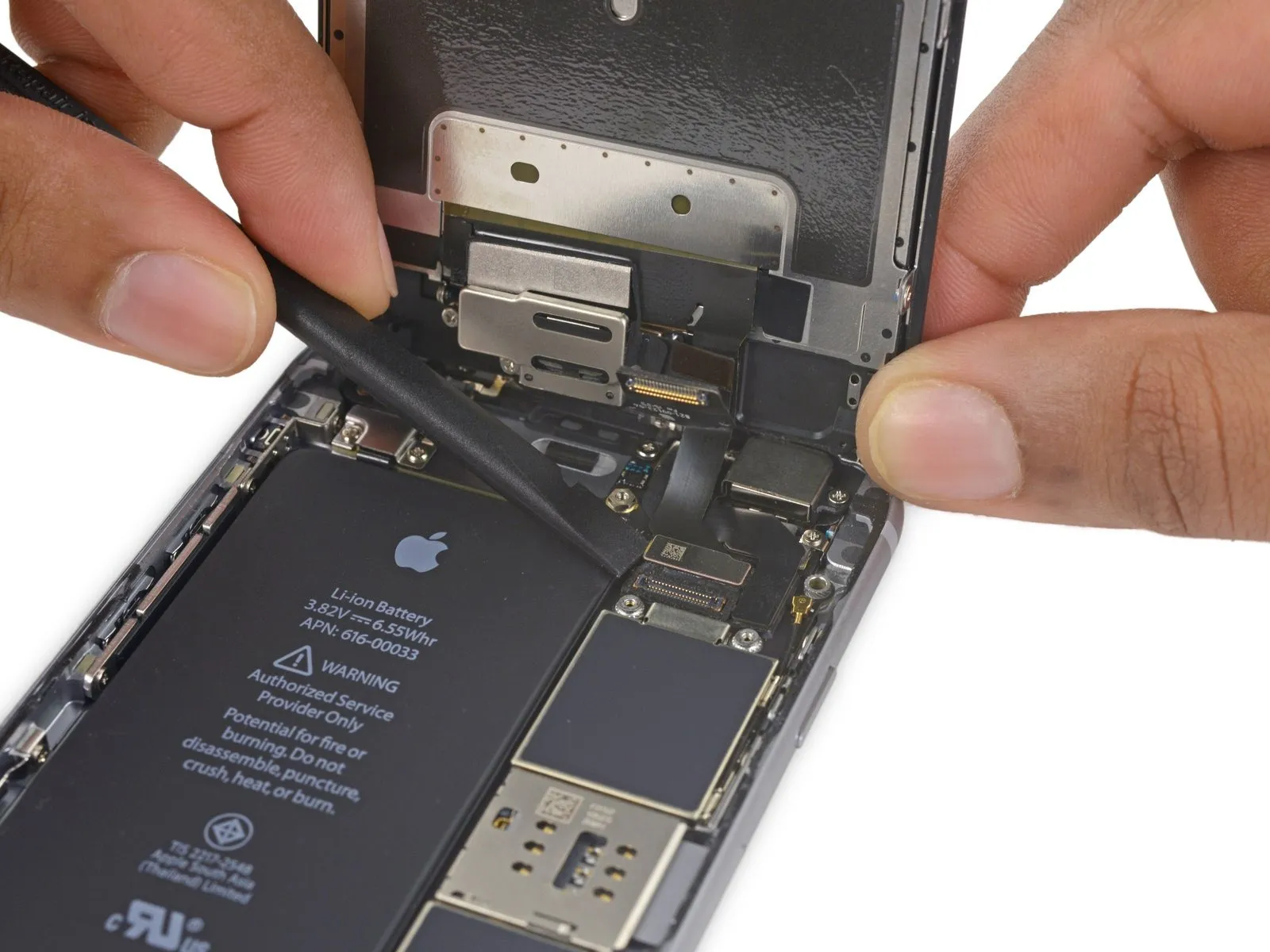
Carefully detach the digitizer cable from its connector on the logic board by applying upward force.
To avoid potential damage to the digitizer, ensure the connector is properly seated by applying pressure to its opposing ends, rather than the central portion; central pressure can distort the component.
To avoid potential damage to the digitizer, ensure the connector is properly seated by applying pressure to its opposing ends, rather than the central portion; central pressure can distort the component.
Step 23
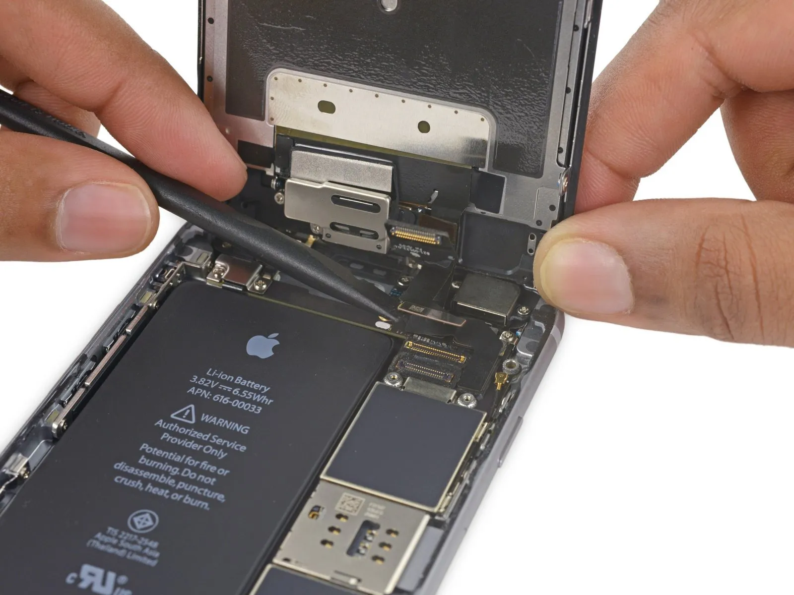
Prior to either detaching or reattaching the cable in this procedure, ensure the battery is disconnected.
Using a prying motion, carefully separate the display cable from its connector on the logic board, ensuring it moves vertically.
Using a prying motion, carefully separate the display cable from its connector on the logic board, ensuring it moves vertically.
Step 24
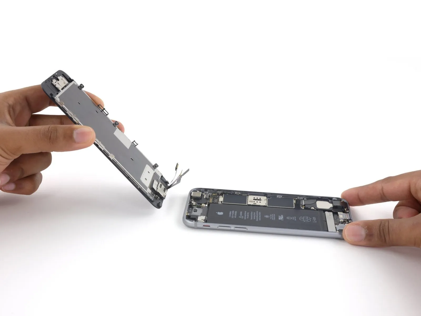
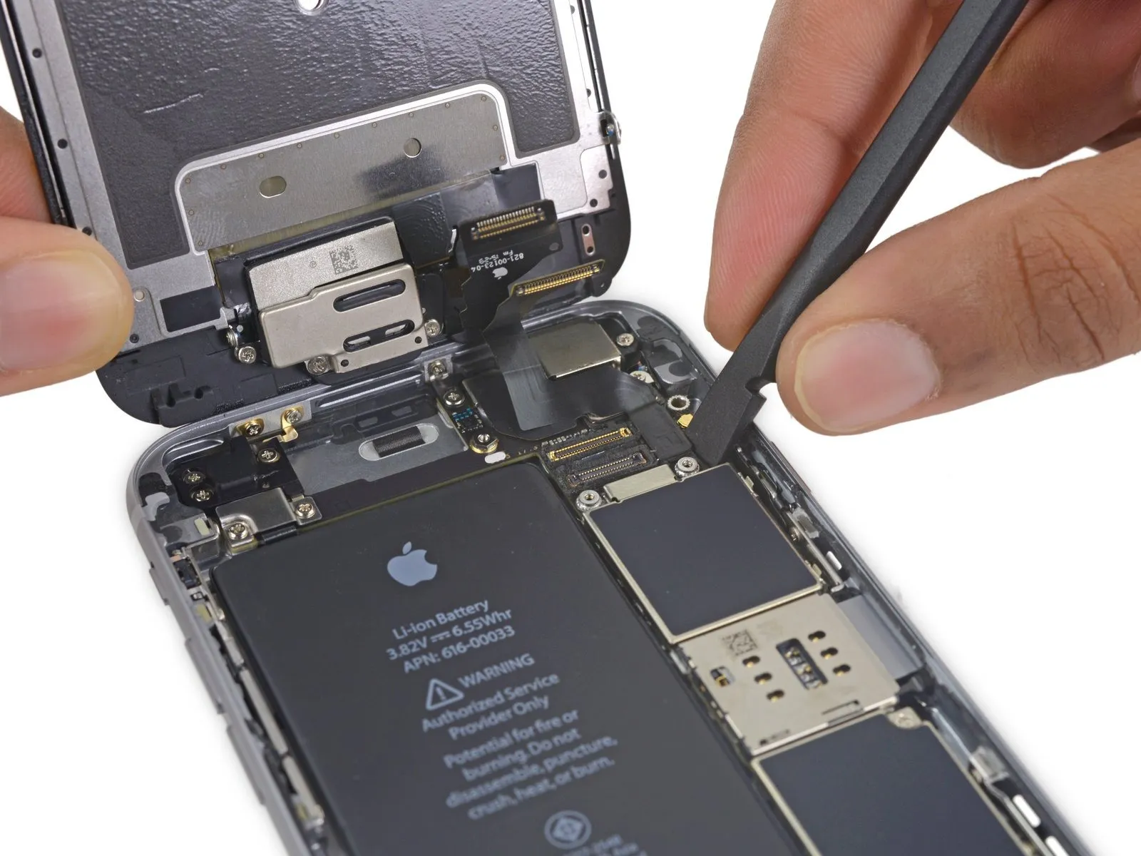
Carefully detach the display assembly, ensuring no damage occurs.
If you intend to substitute fresh adhesive along the display's perimeter during reassembly, stop at this point.
If you intend to substitute fresh adhesive along the display's perimeter during reassembly, stop at this point.
Step 25 | Rear Camera
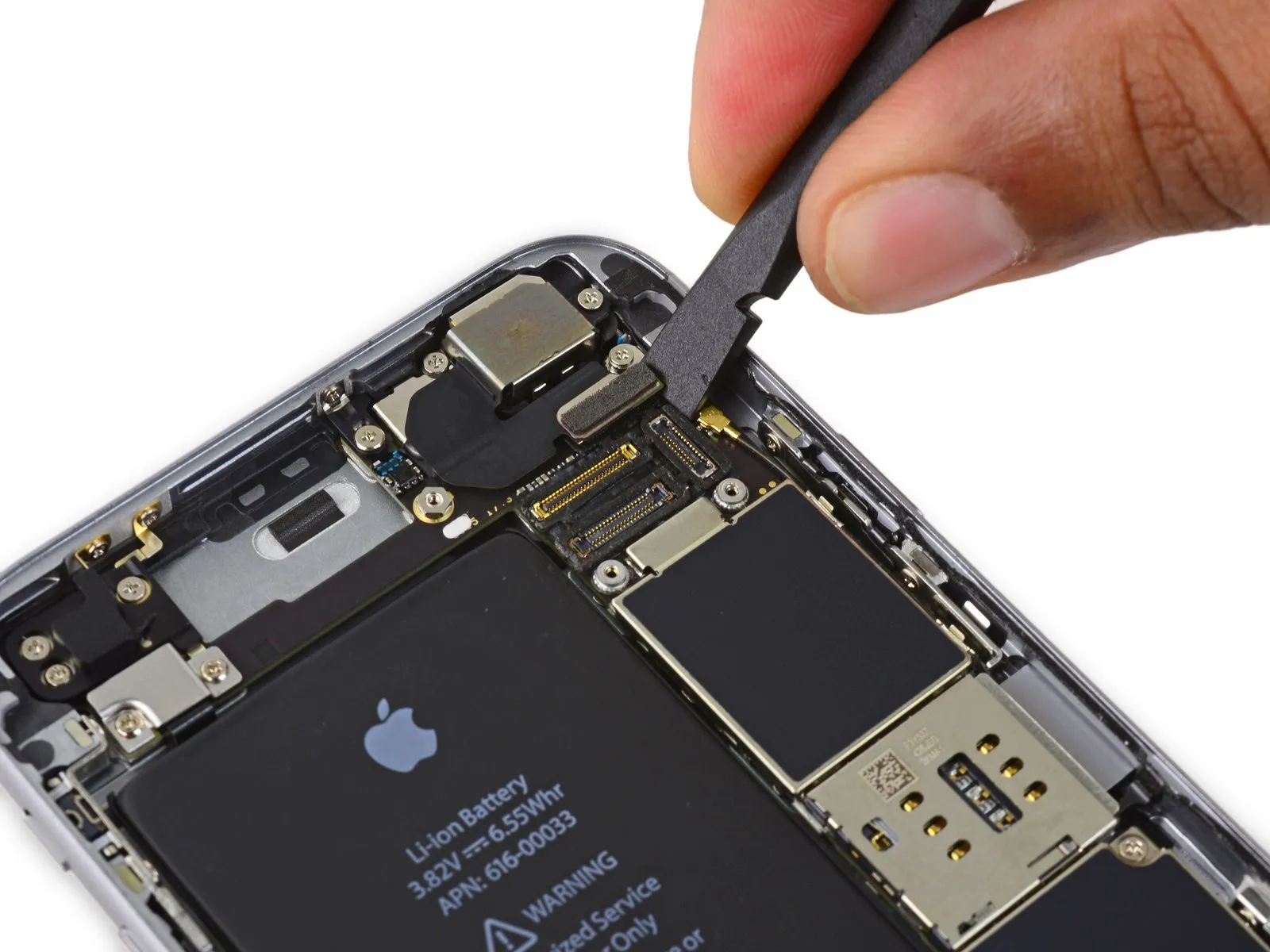
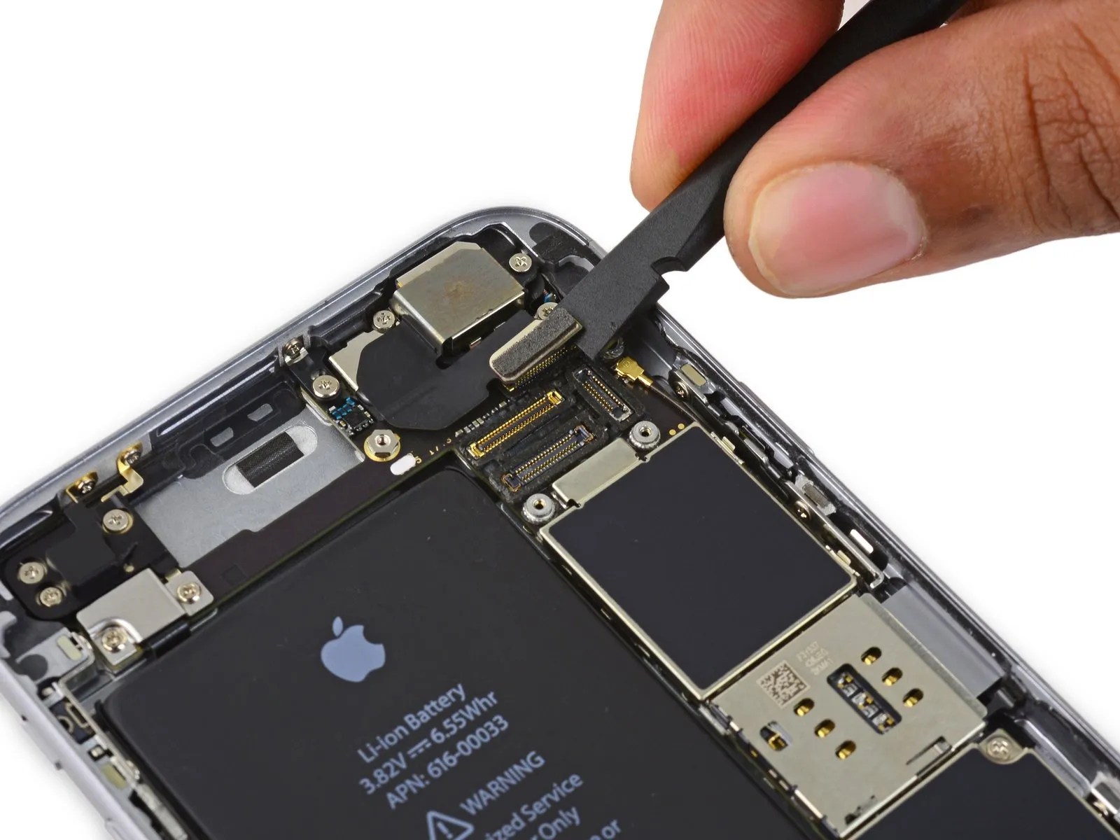
Carefully separate the rear camera connector from the logic board's socket using the flat spudger.
Step 26

Using a Phillips screwdriver, detach the two screws located above the rear camera bracket.
A screw with a 1.6 mm diameter is required.
A screw with a 2.0 mm diameter is required.
A screw with a 1.6 mm diameter is required.
A screw with a 2.0 mm diameter is required.
Step 27

Detach the camera mounting bracket.
Step 28
Using a spudger, gently slide it into the space located alongside the camera assembly, separating the rear case from the camera module.
Using careful, controlled force, disengage the camera from its housing by applying upward pressure.
Using careful, controlled force, disengage the camera from its housing by applying upward pressure.
Step 29
Carefully detach the camera assembly.
Step 30 | SIM Tray
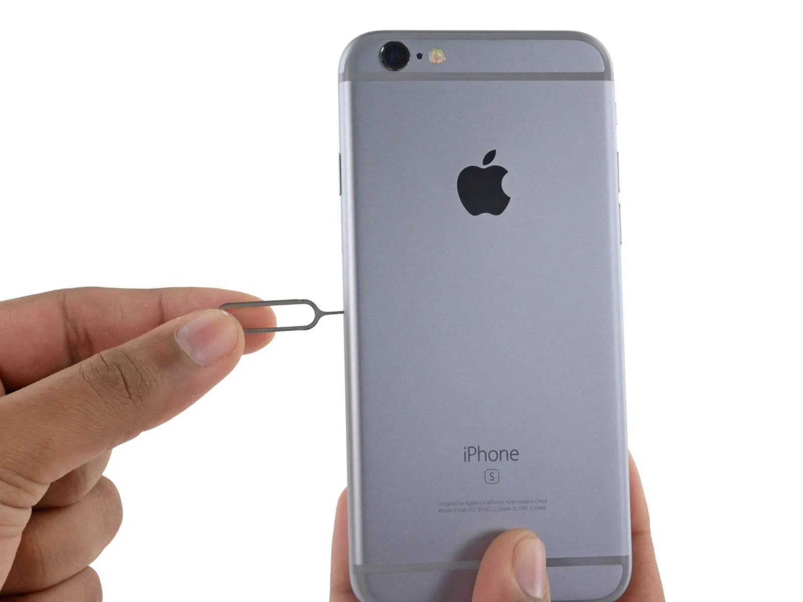
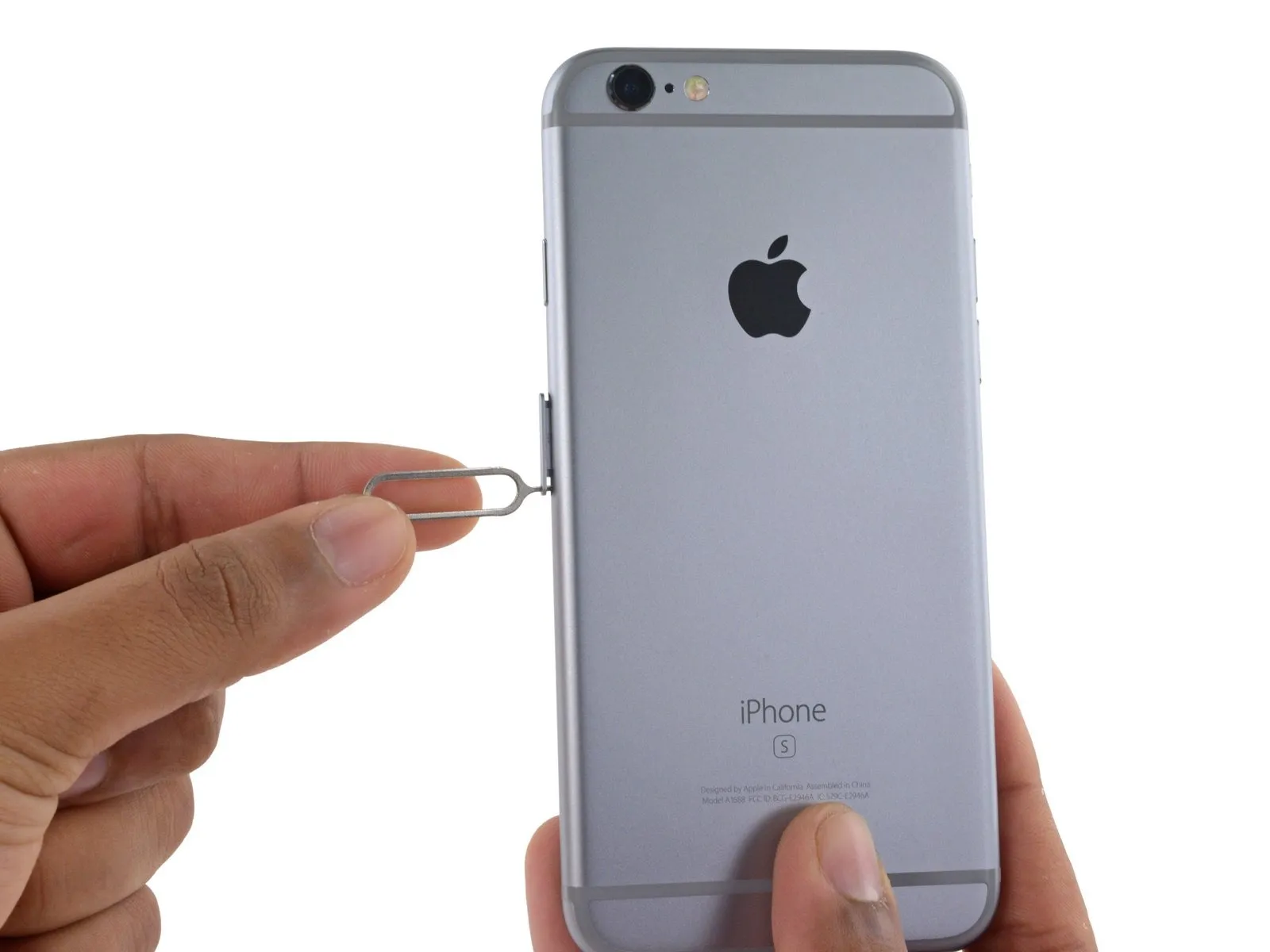
Using a SIM card eject tool or a straightened paperclip, gently push into the tiny aperture located on the SIM card tray to release it.
Apply force to release the tray from its housing.
Applying considerable pressure might be necessary.
Apply force to release the tray from its housing.
Applying considerable pressure might be necessary.
Step 31
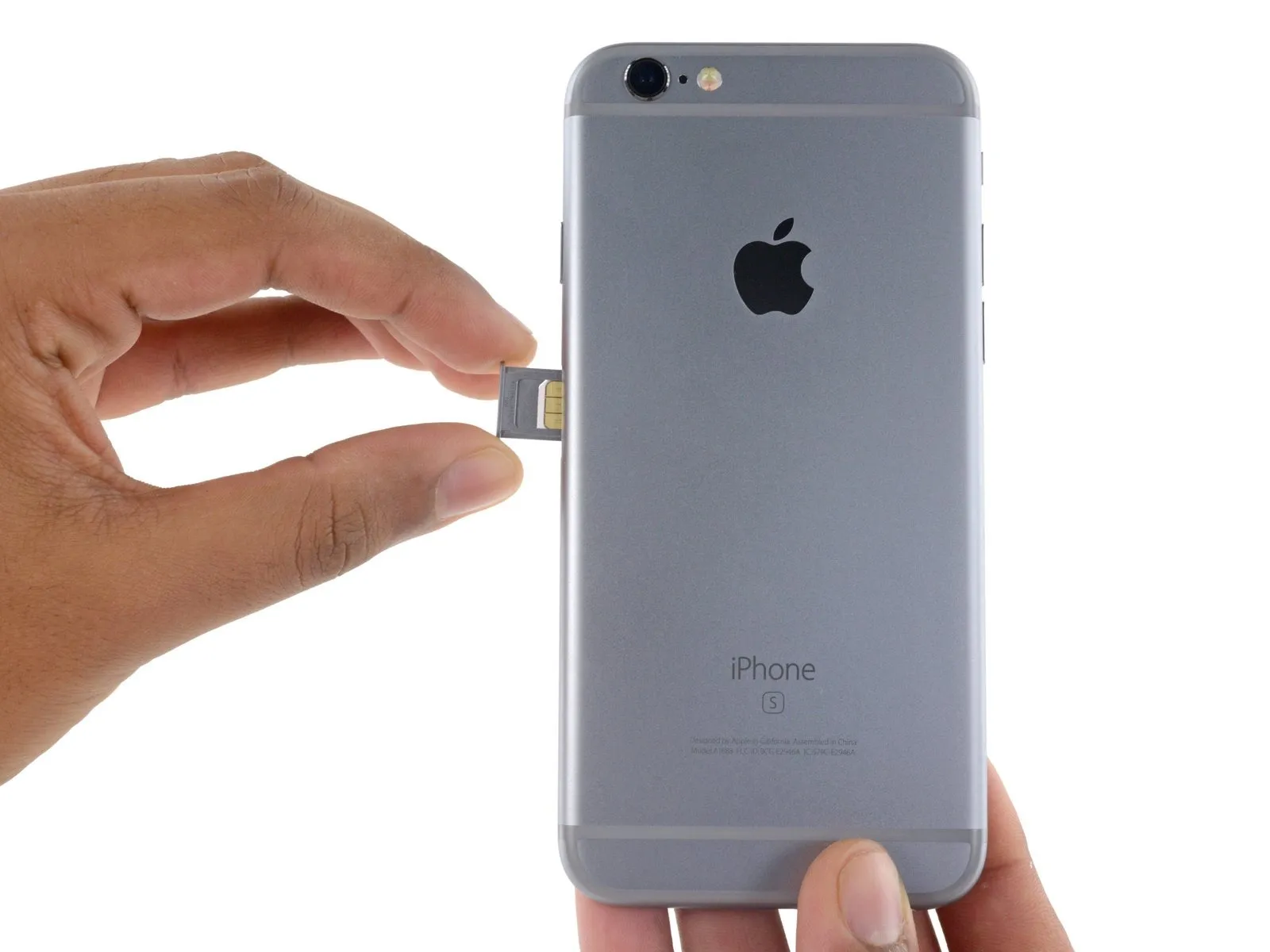
Using the SIM ejection tool or a small, appropriately sized metal object, release the SIM Card tray and extract the SIM Card tray assembly from the iPhone.
Confirm the SIM card's alignment within the tray before sliding it back in, matching its position to the tray's design.
Confirm the SIM card's alignment within the tray before sliding it back in, matching its position to the tray's design.
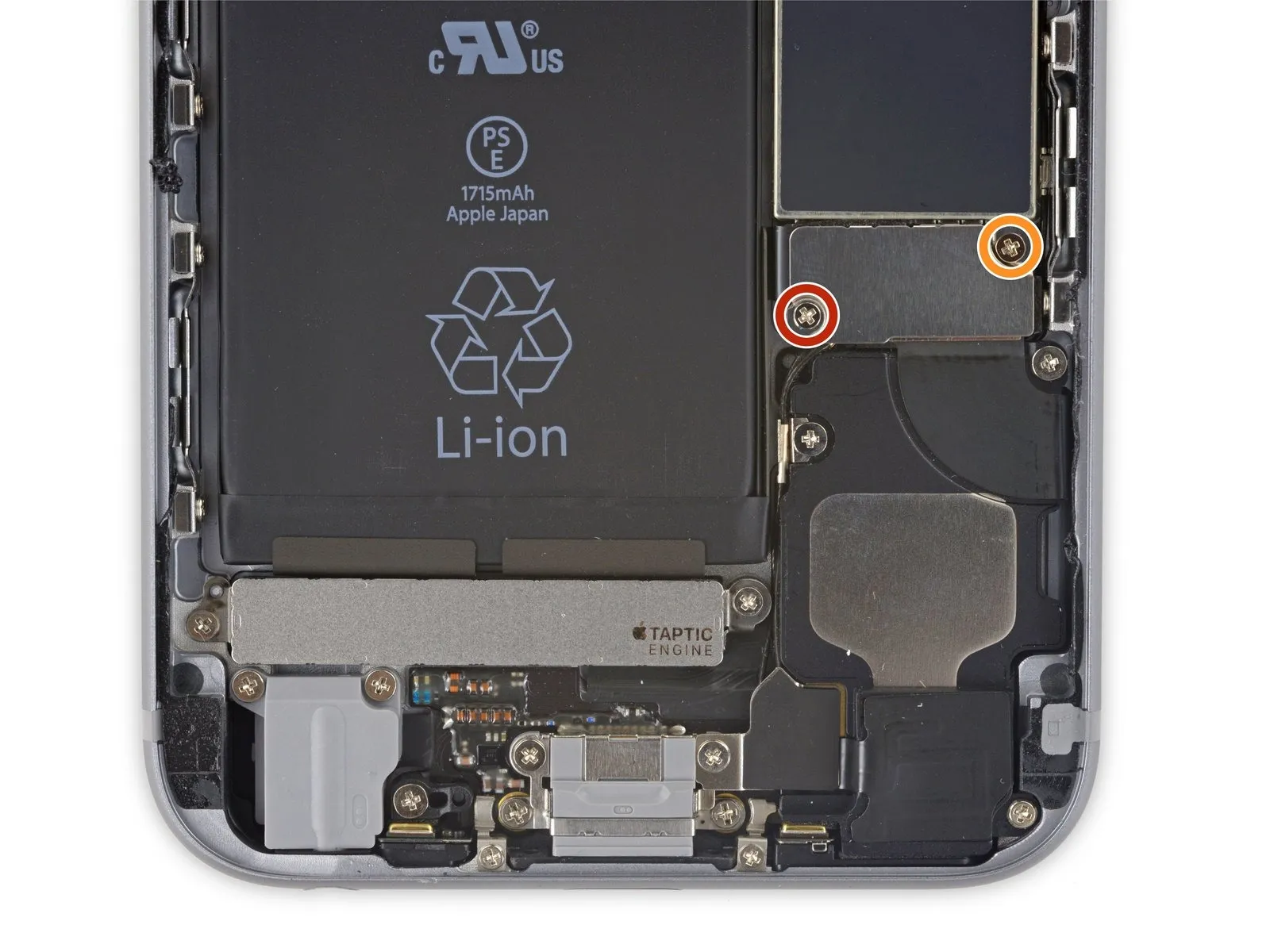
Step 32 | Logic Board
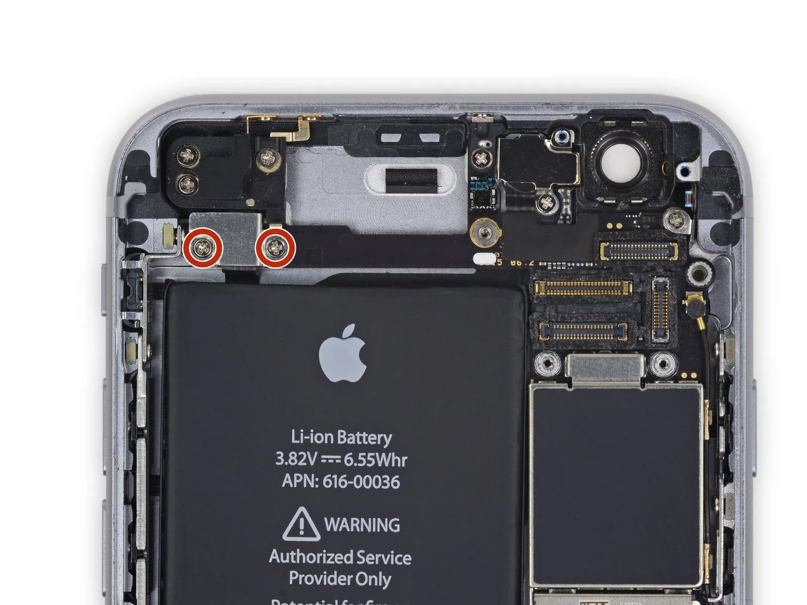
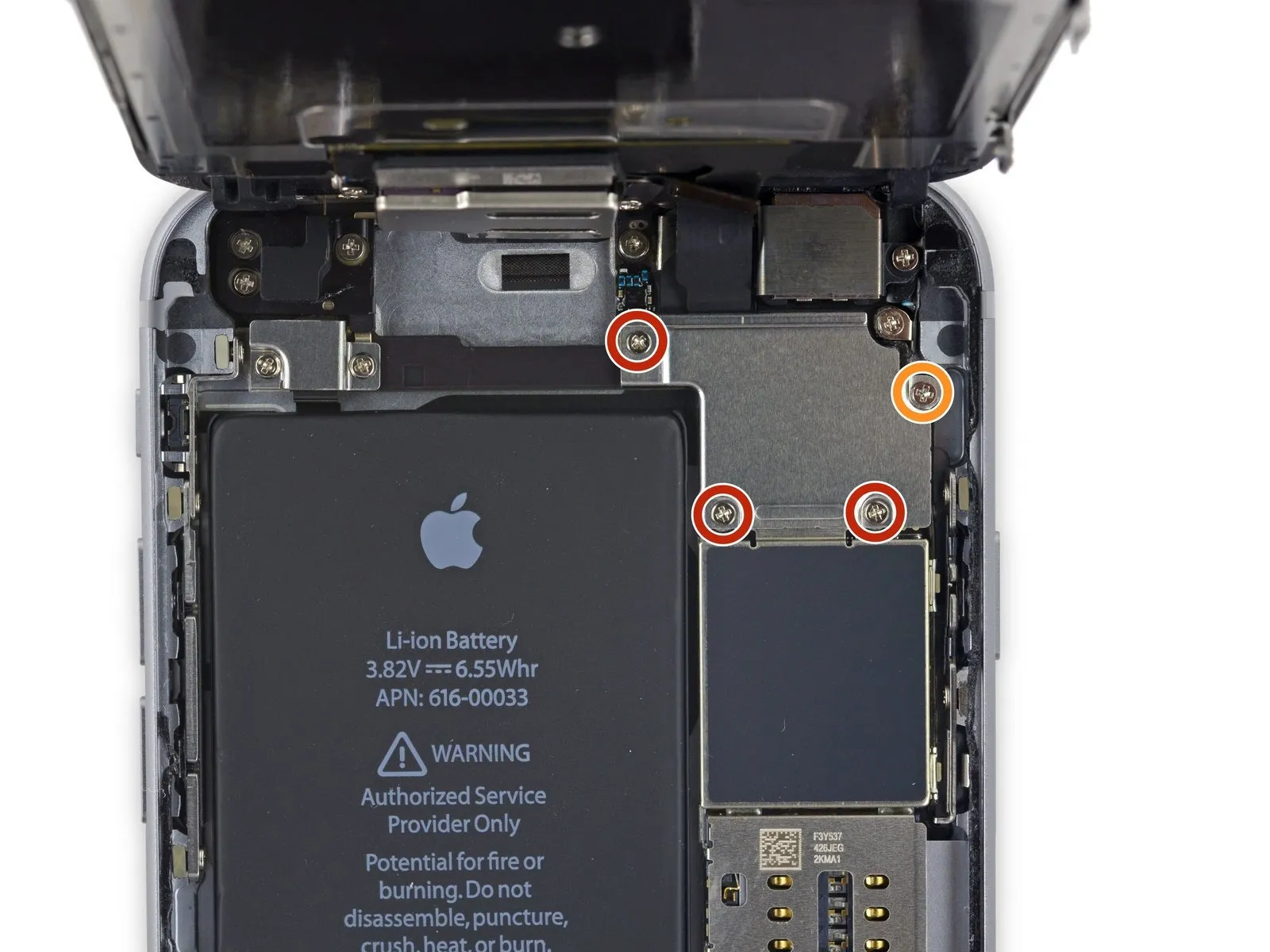
Using a Phillips screwdriver, detach the bracket that holds the upper component cable connector by unscrewing the two fasteners, each measuring 2.3 mm.
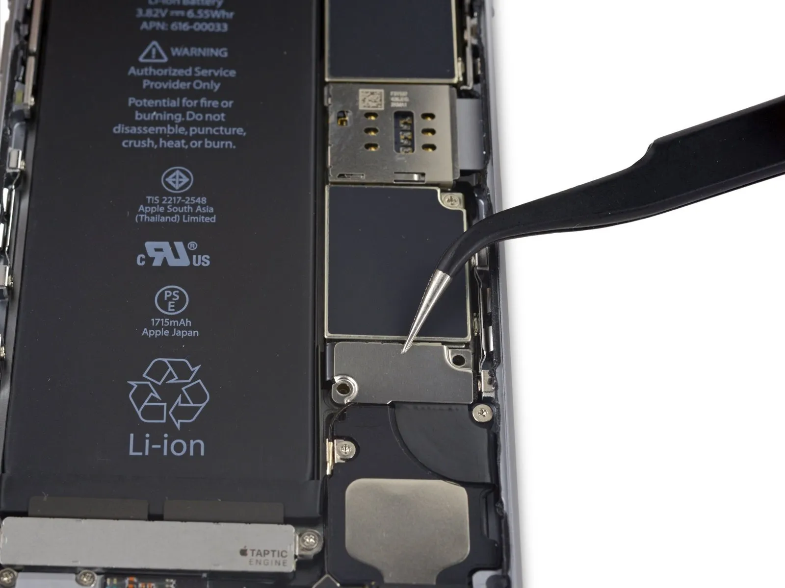
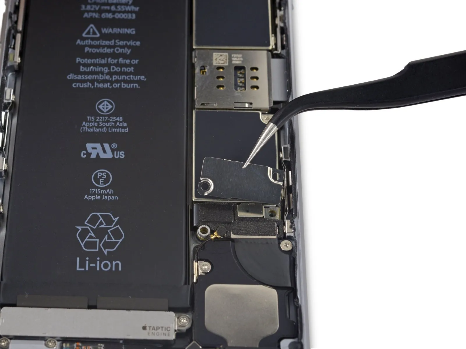
Step 33
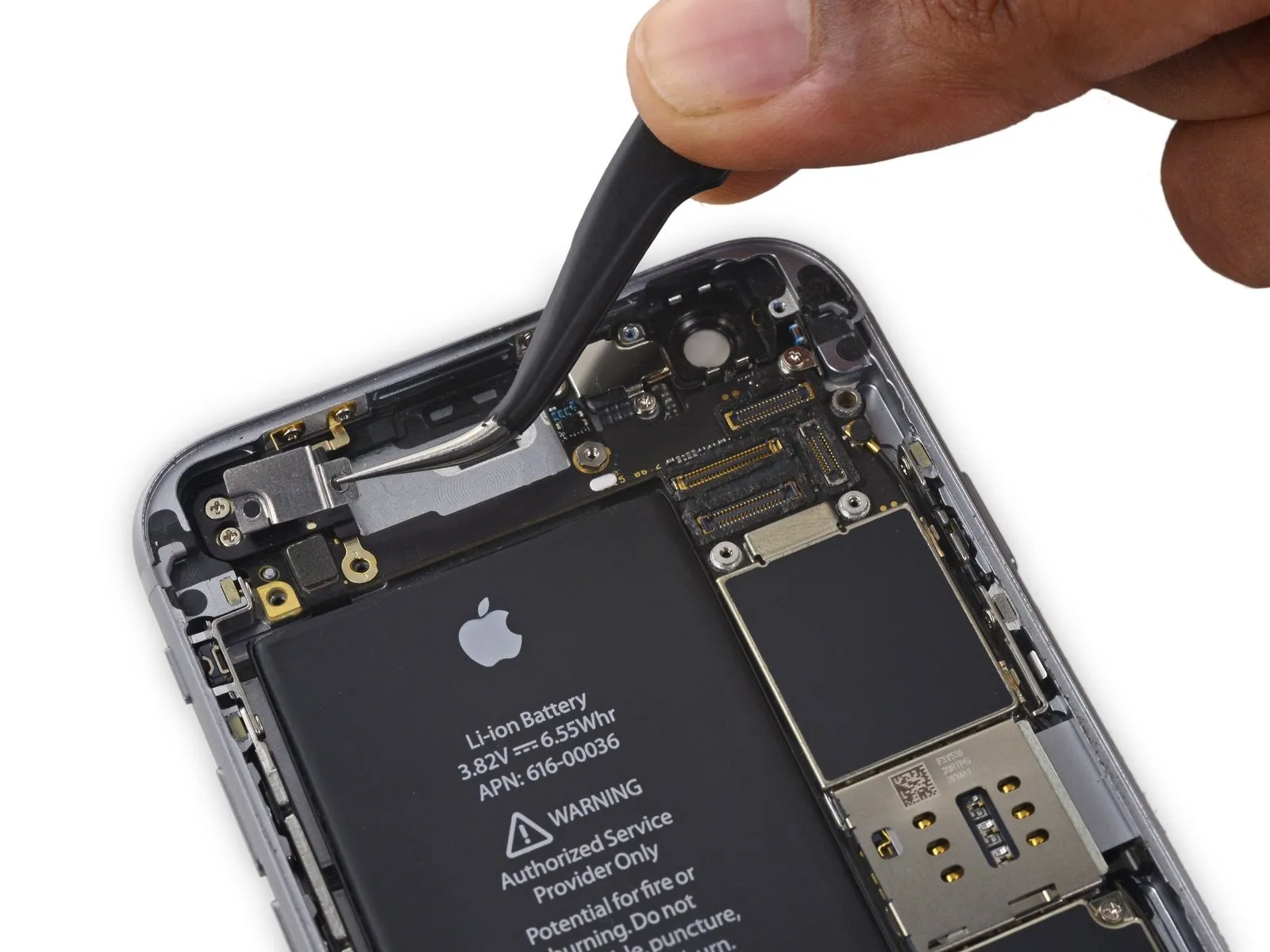

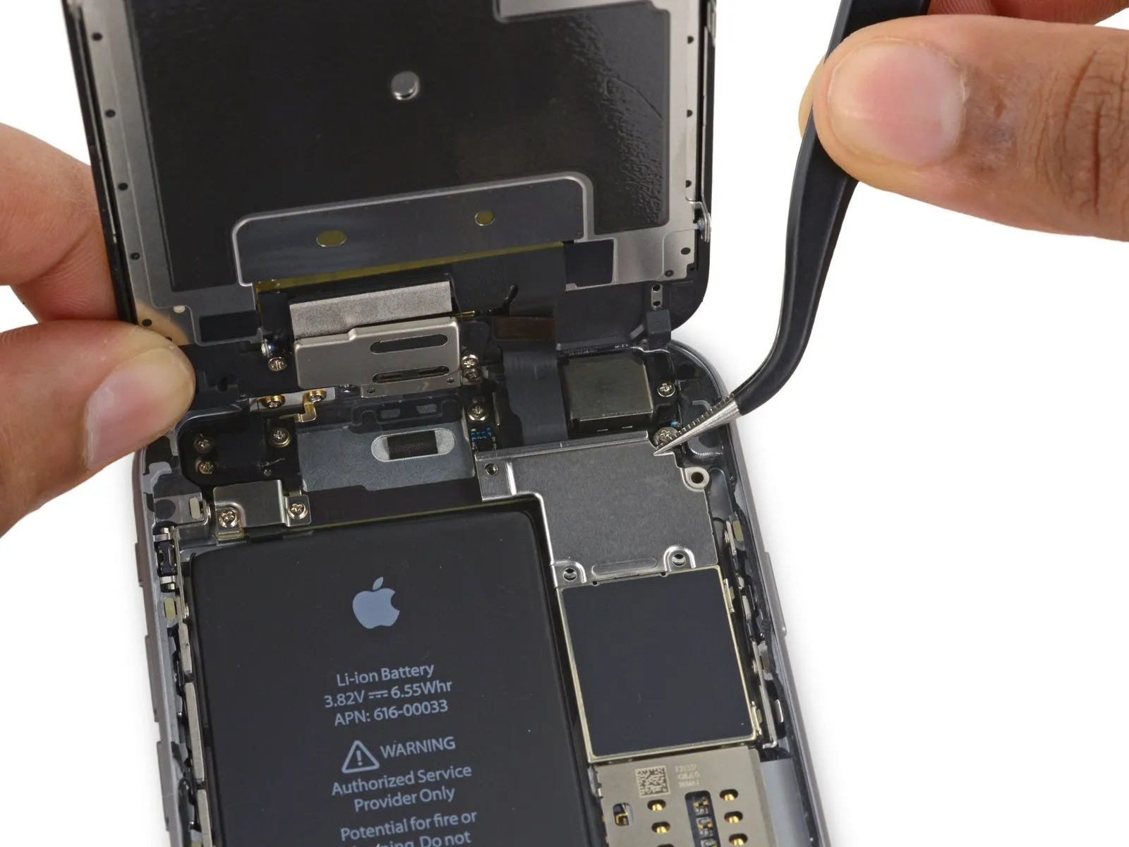
Detach the bracket securing the upper component cable connector.
Step 34

Using a Phillips screwdriver, detach the five screws that fasten the top left Wi-Fi antenna in place.
Use screws, each measuring 1.5 millimeters in diameter.
A screw with a 2.3 mm diameter is required.
A screw with a 1.9 mm diameter is required.
A screw with a 2.0 mm diameter is required.
Use screws, each measuring 1.5 millimeters in diameter.
A screw with a 2.3 mm diameter is required.
A screw with a 1.9 mm diameter is required.
A screw with a 2.0 mm diameter is required.
Step 35

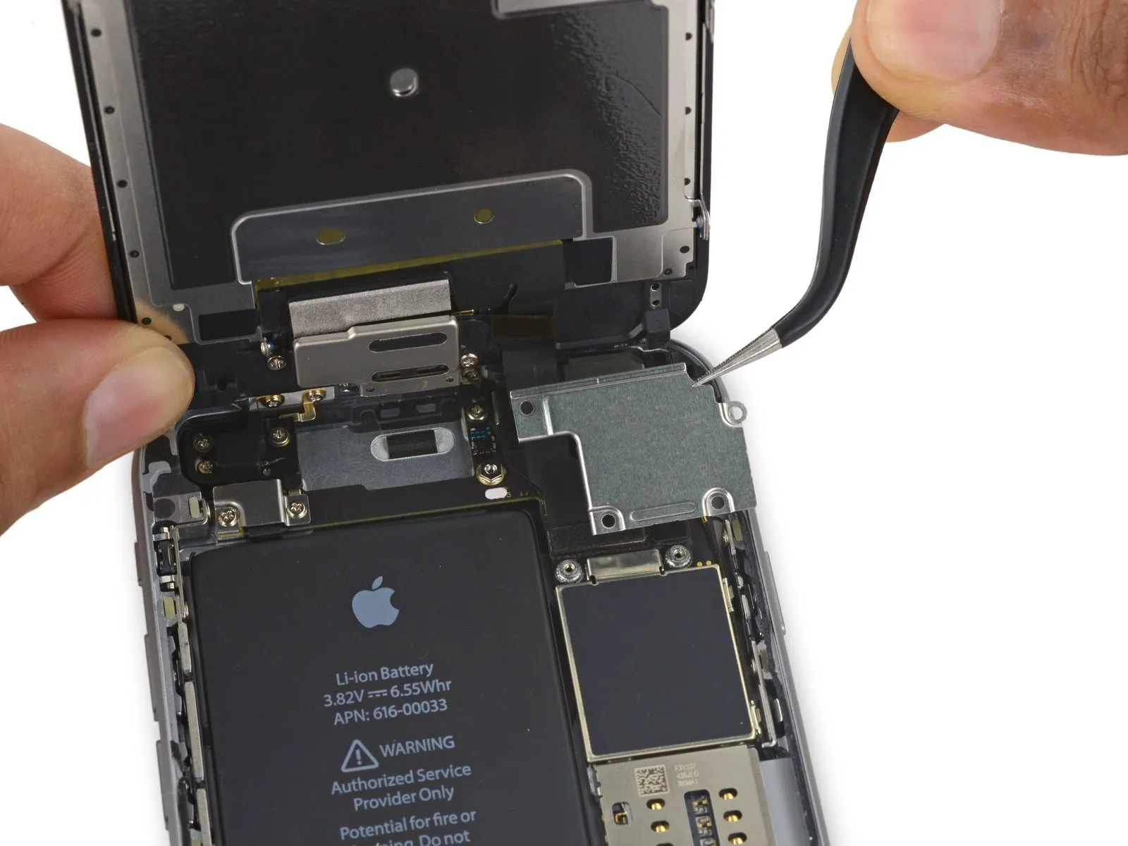
Detach the Wi-Fi antenna located on the device's upper left side.
Step 36
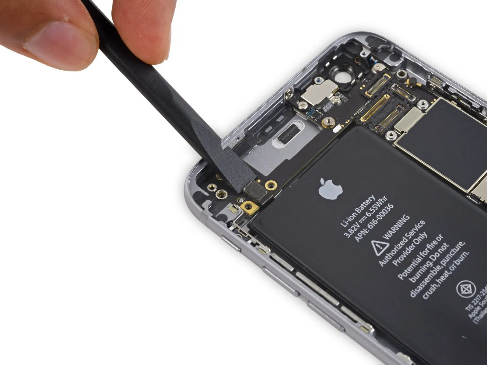
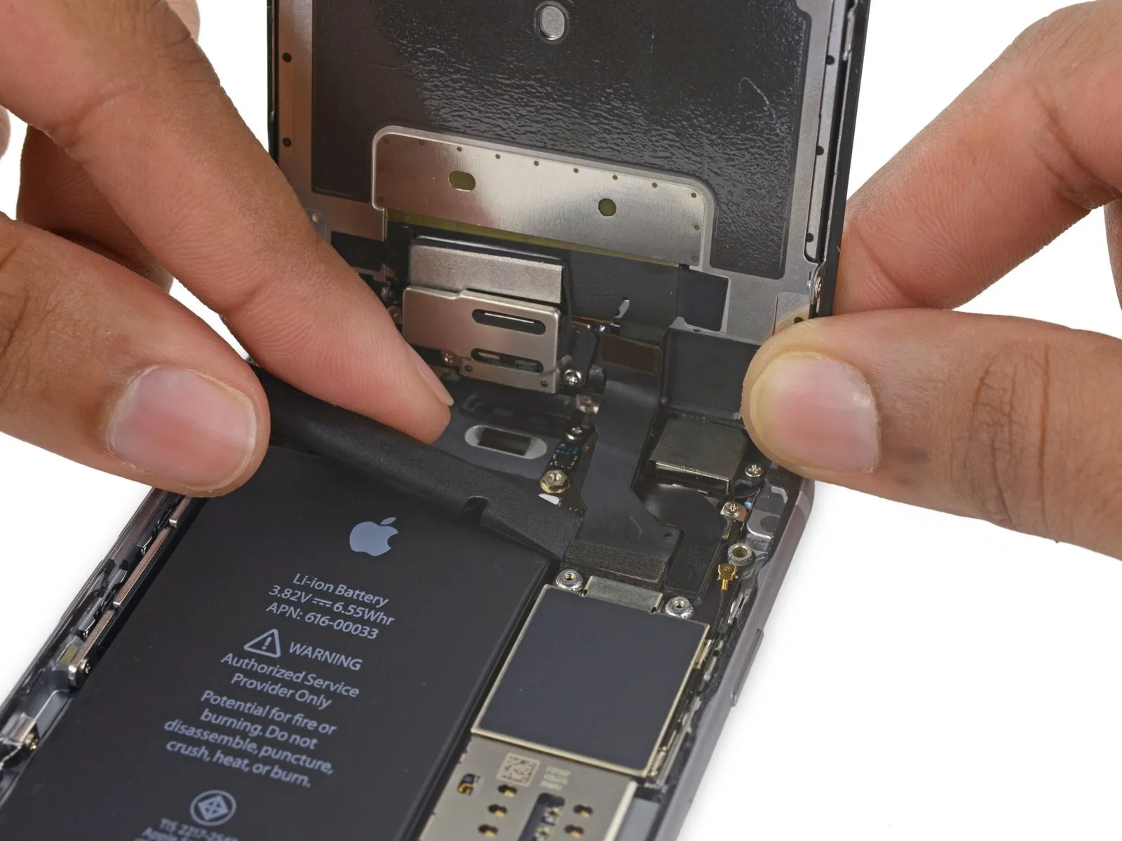
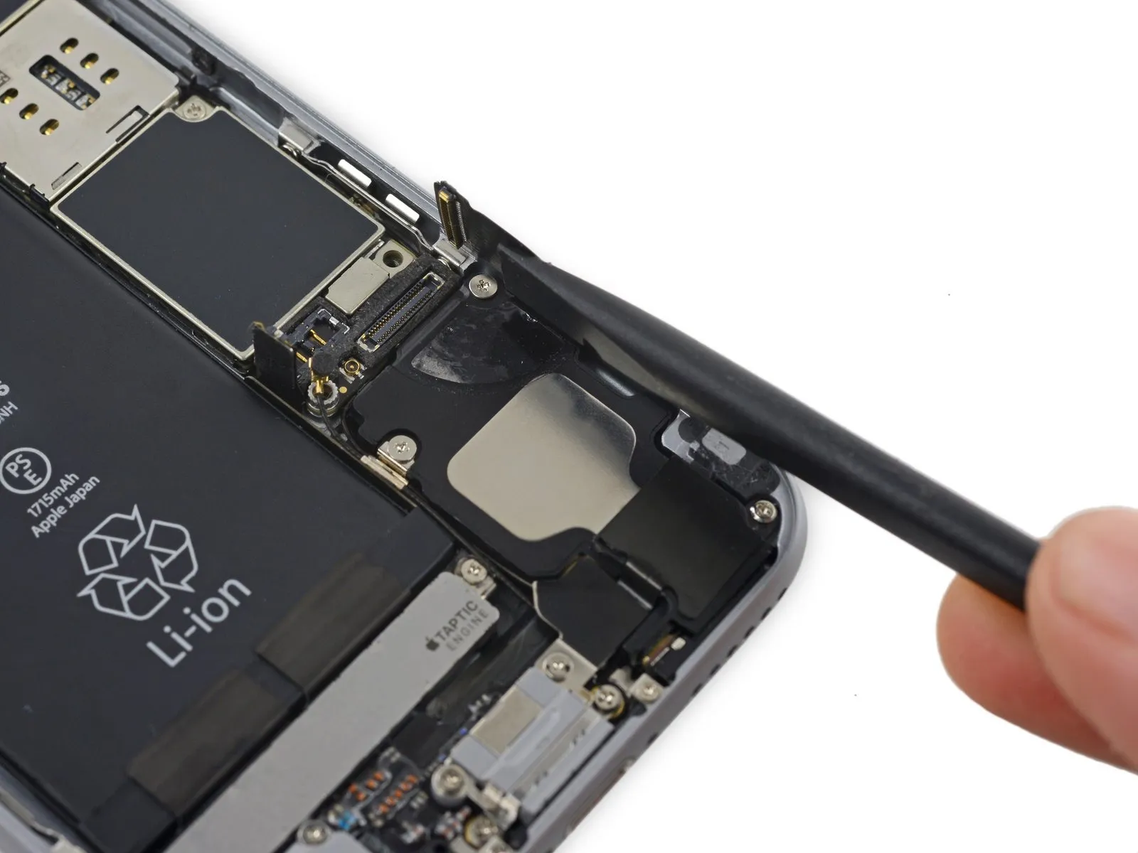
Employing the flat spudger tip, carefully separate the audio control cable connector from its corresponding socket on the logic board.
Step 37


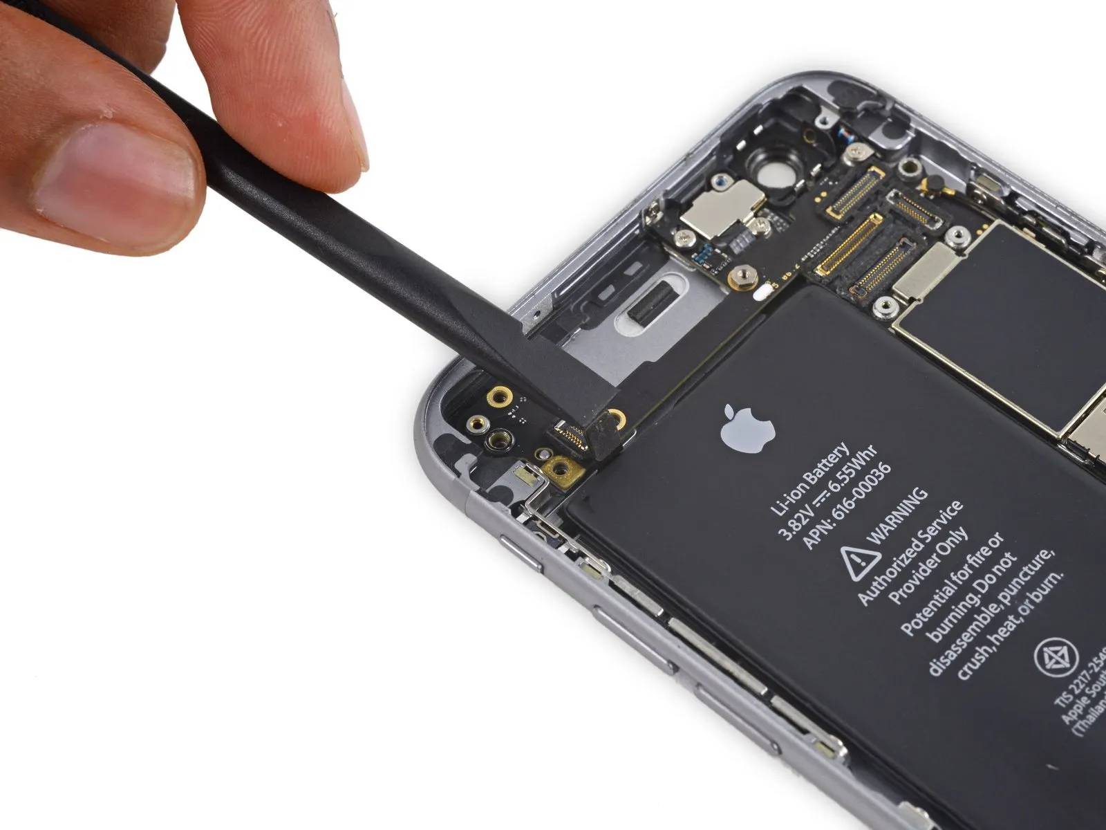
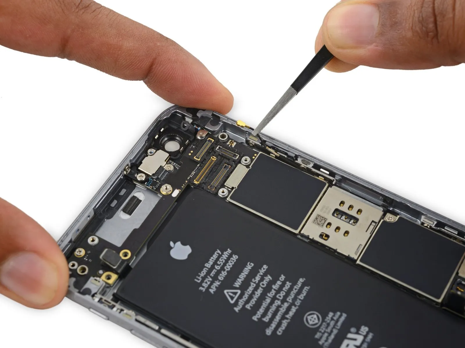
Carefully detach the antenna cable from its connector, located in the upper right corner of the logic board, by using the pointed end of a spudger.
Step 38

Carefully detach the antenna cable from its connector, located in the lower left corner of the logic board, by using the tip of a spudger.
Step 39
Using a spudger, carefully slide the flat tip beneath the Lightning connector ribbon cable and gently pry upwards to release it from its connection on the logic board.
Step 40

To disconnect the antenna cable, carefully lift it upwards, releasing it from the two retaining clips located on the logic board’s right-hand side.
Step 41

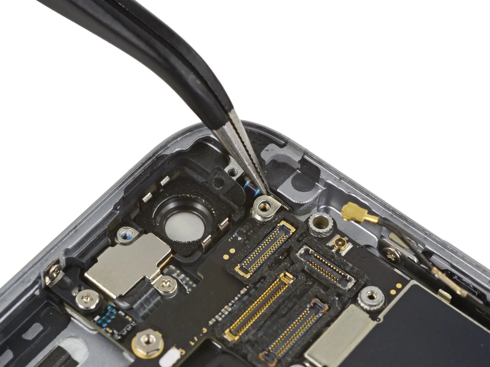
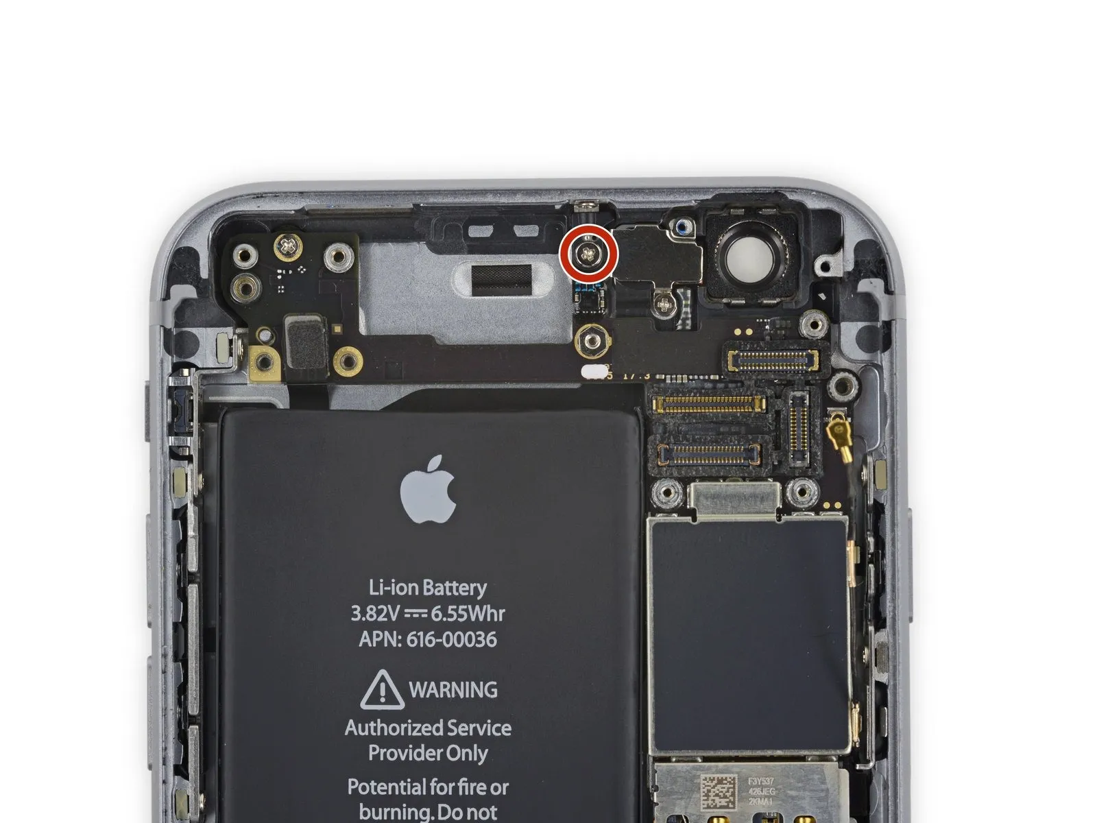
Using a Phillips screwdriver, detach the NFC bracket from the logic board by unscrewing the 1.3 mm screw that holds it in place.
Step 42

Detach the near-field communication component's mounting bracket.
Step 43

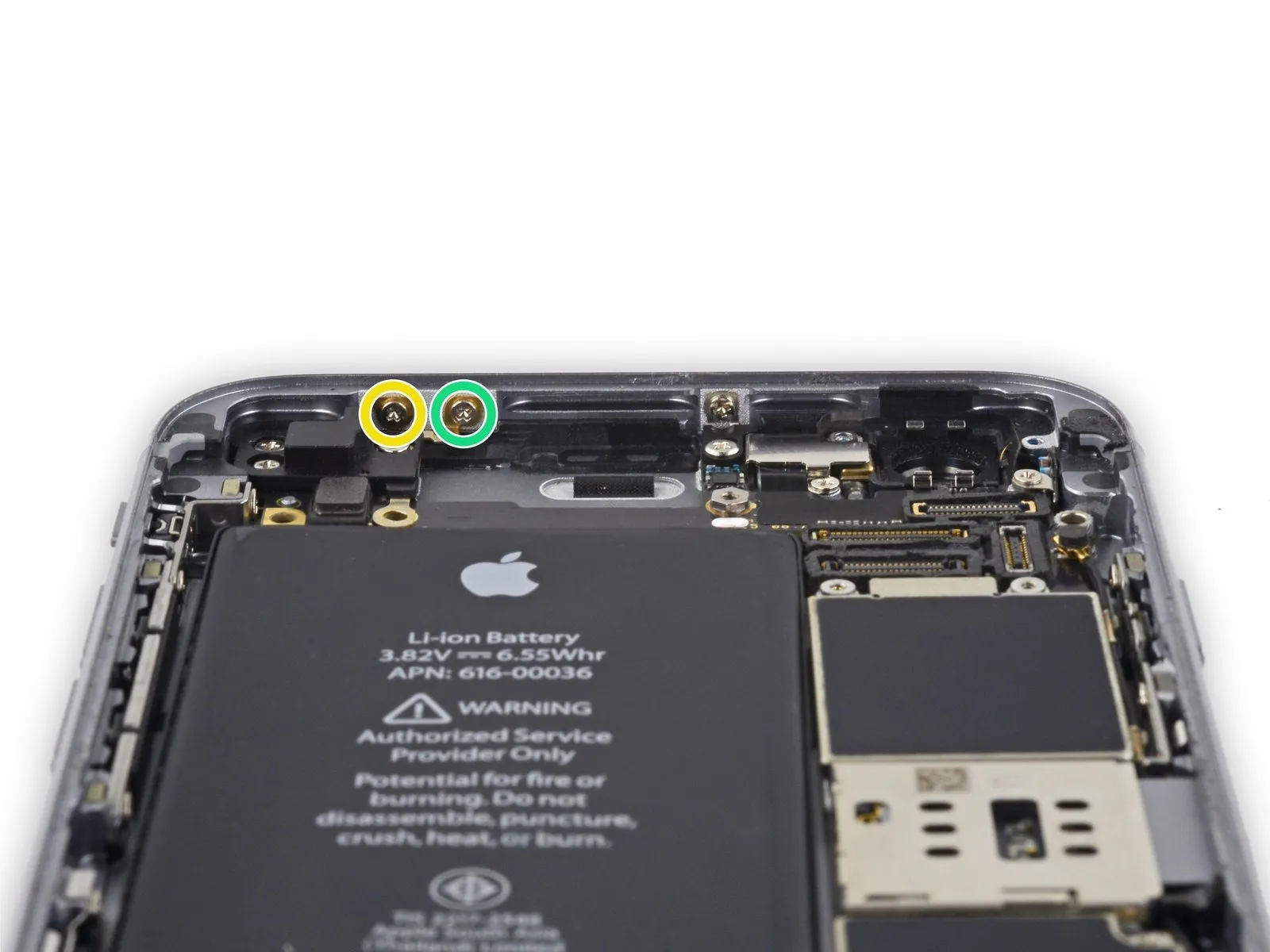
Using the appropriate screwdriver, detach the two screws.
- A single screw, measuring 2.5 millimeters, secures the logic board at its upper edge.
- A 1.4 mm screw secures the rear case to the upper edge.
Step 44

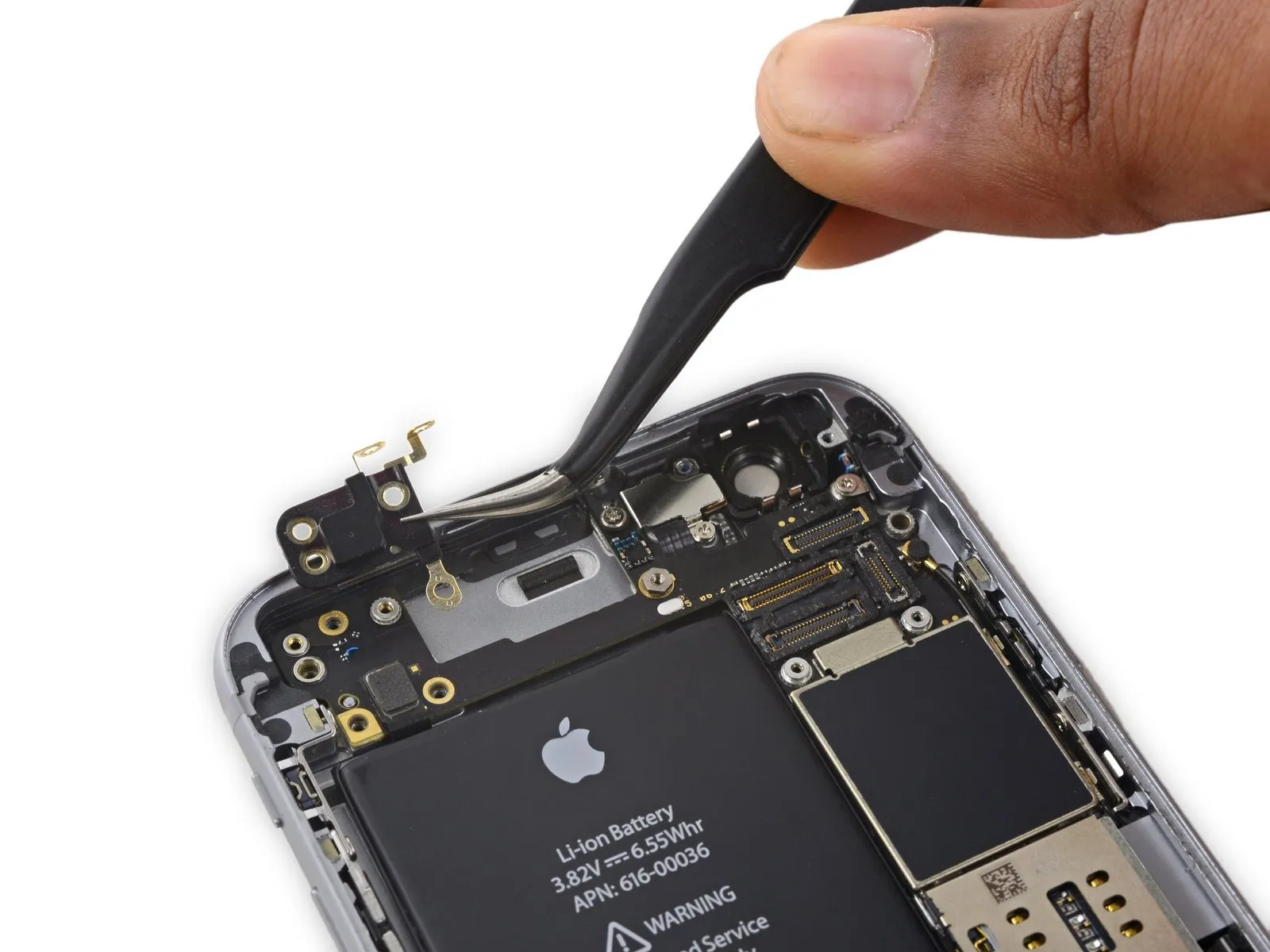
Detach the retaining clip, which is fabricated from plastic.
Step 45

Using a screwdriver, detach the logic board from the rear case by unscrewing the last three screws.
- Use a Phillips screwdriver to remove a single screw with a 1.9 mm head.
- A 2.5-millimeter hex nut is required.
- Use a Phillips screwdriver to remove a single screw measuring 1.8 millimeters.
Step 46
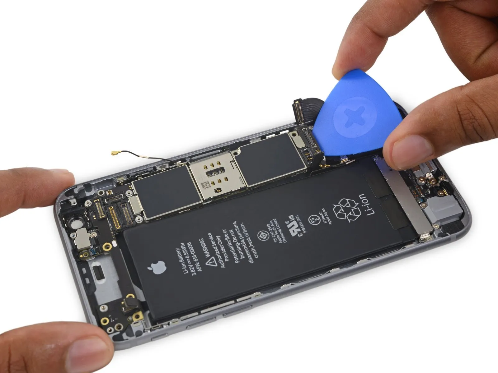
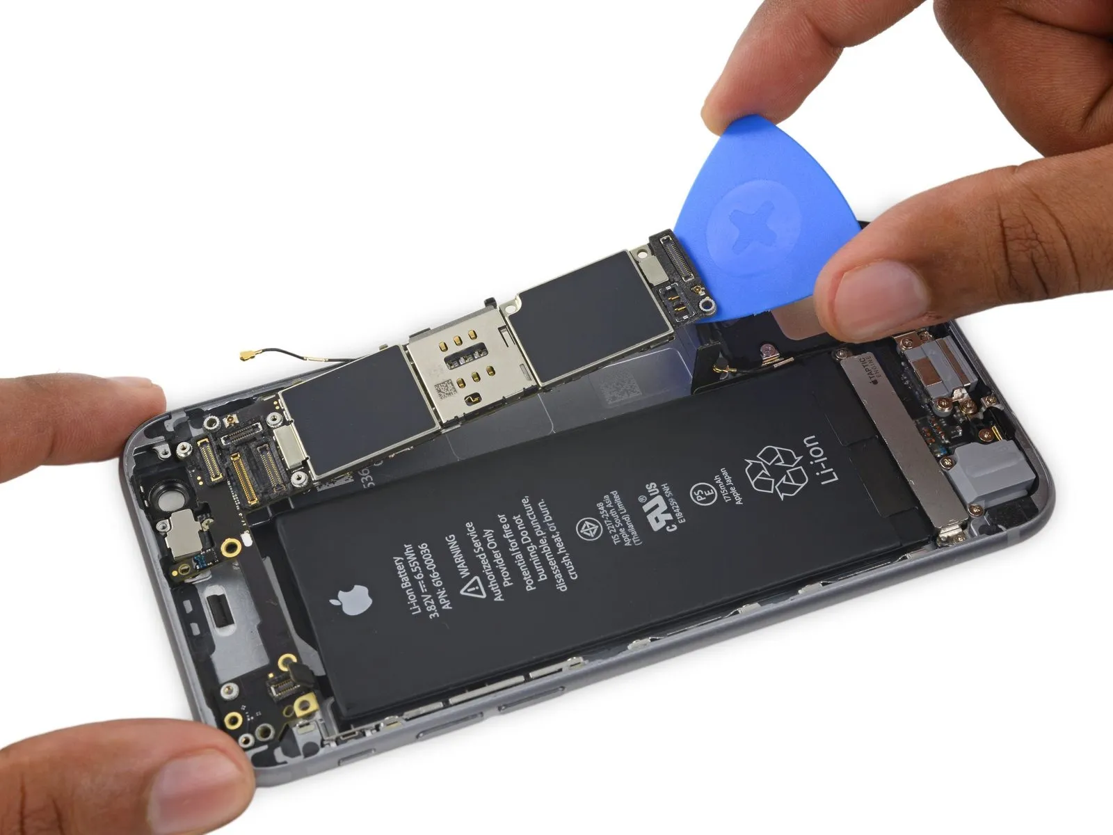
- Using a pick, carefully slide it under the logic board's bottom edge, positioning it between the board and the loudspeaker.
- Carefully disengage the logic board from its enclosure using the opening pick, applying gentle force.
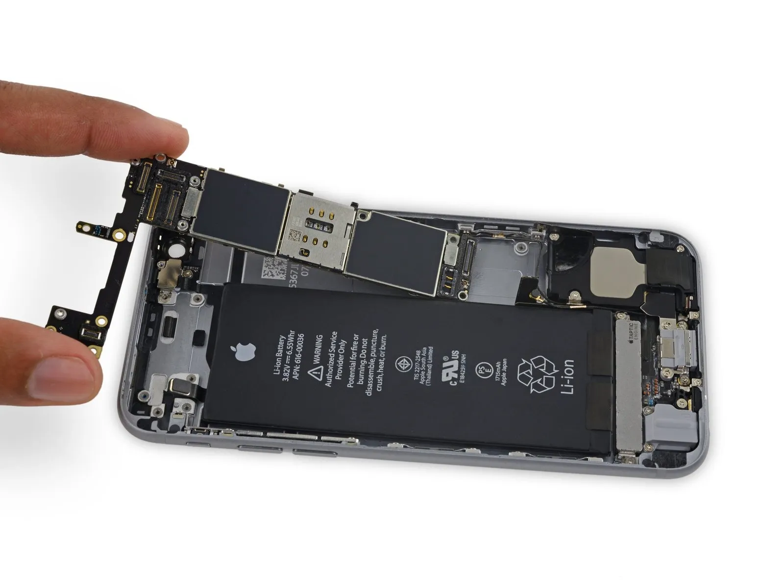
- Carefully detach the logic board, ensuring all connections are fully disengaged.
Step 47 | Upper Component Cable
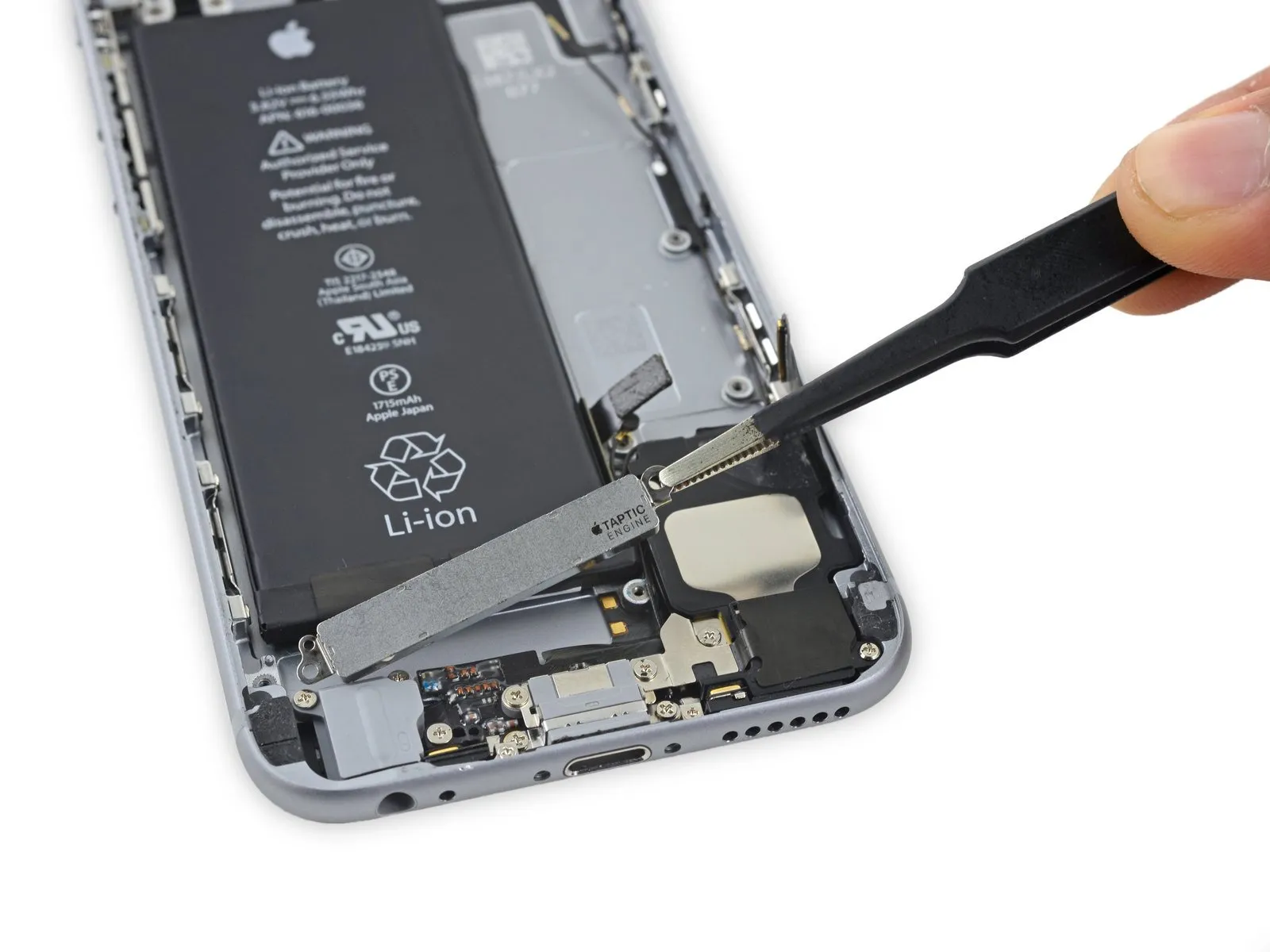
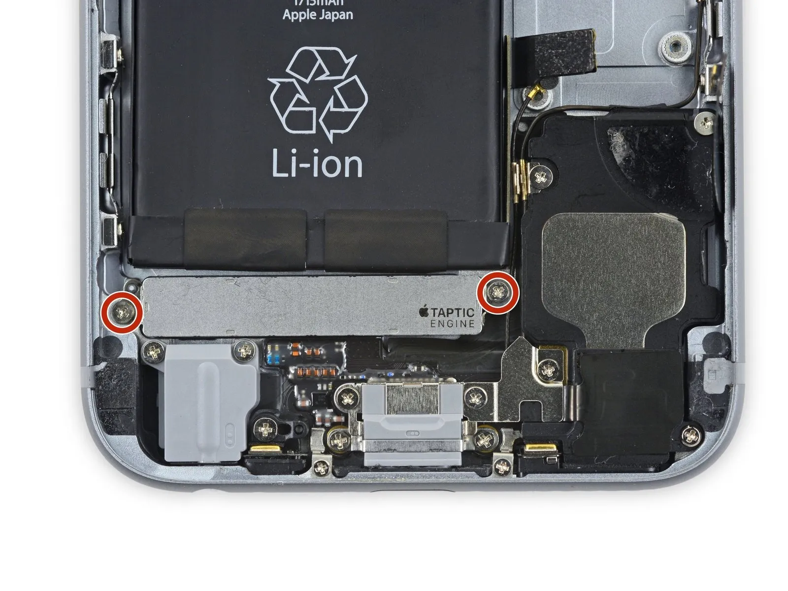
- Using a Phillips screwdriver, detach the Taptic Engine by unscrewing the two fasteners secured with 1.5 mm threads.
- Carefully detach the Taptic Engine, ensuring no damage occurs.
Step 48
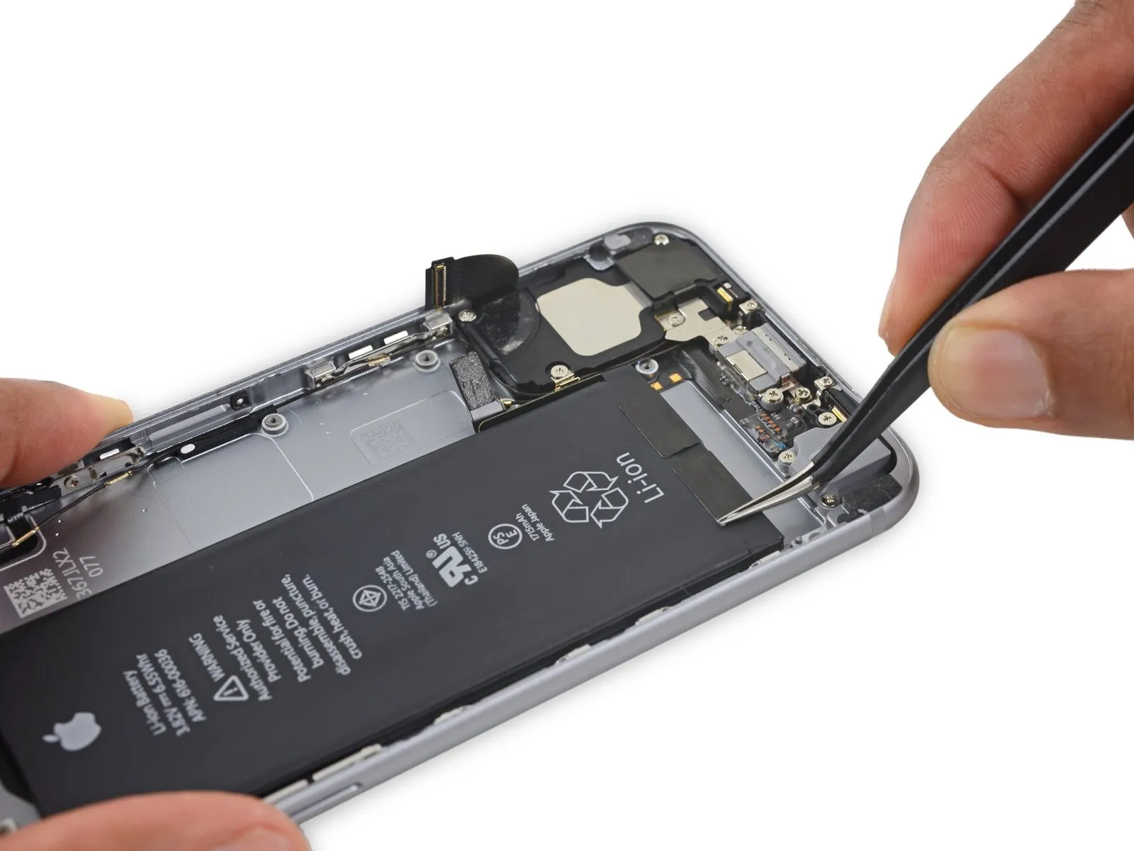

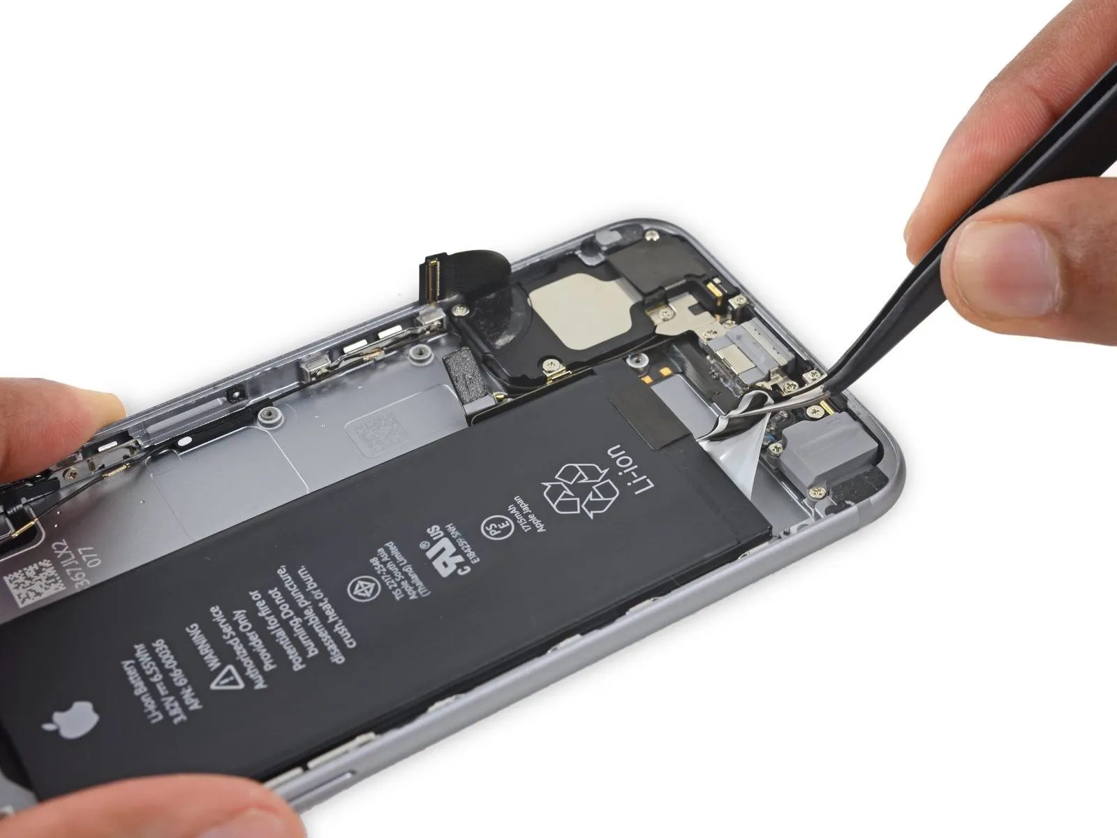
Carefully lift the battery adhesive strip ends along the bottom edge by utilizing tweezers.
Step 49
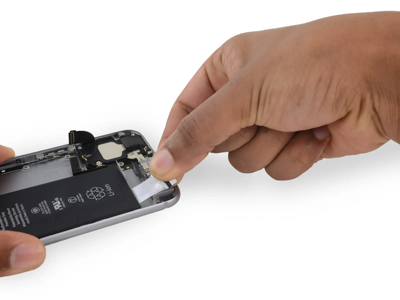

- Care should be taken to avoid creasing the strips; once folded, they are unrecoverable and will be challenging to manipulate.
- To release the adhesive, grasp one of the strips and draw it downward, away from the iPhone's top edge, ensuring the pulling angle remains at 60 degrees or less to maximize effectiveness.
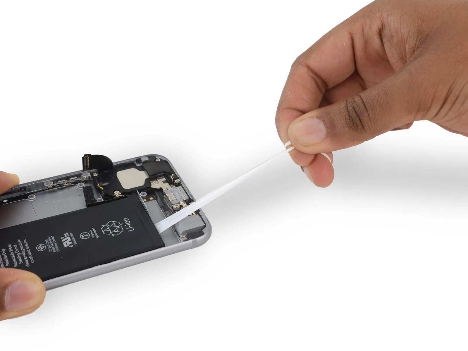
- Expect the adhesive strip to extend significantly beyond its initial size; maintain consistent pulling force, repositioning your grip along the strip's length toward the iPhone as needed.
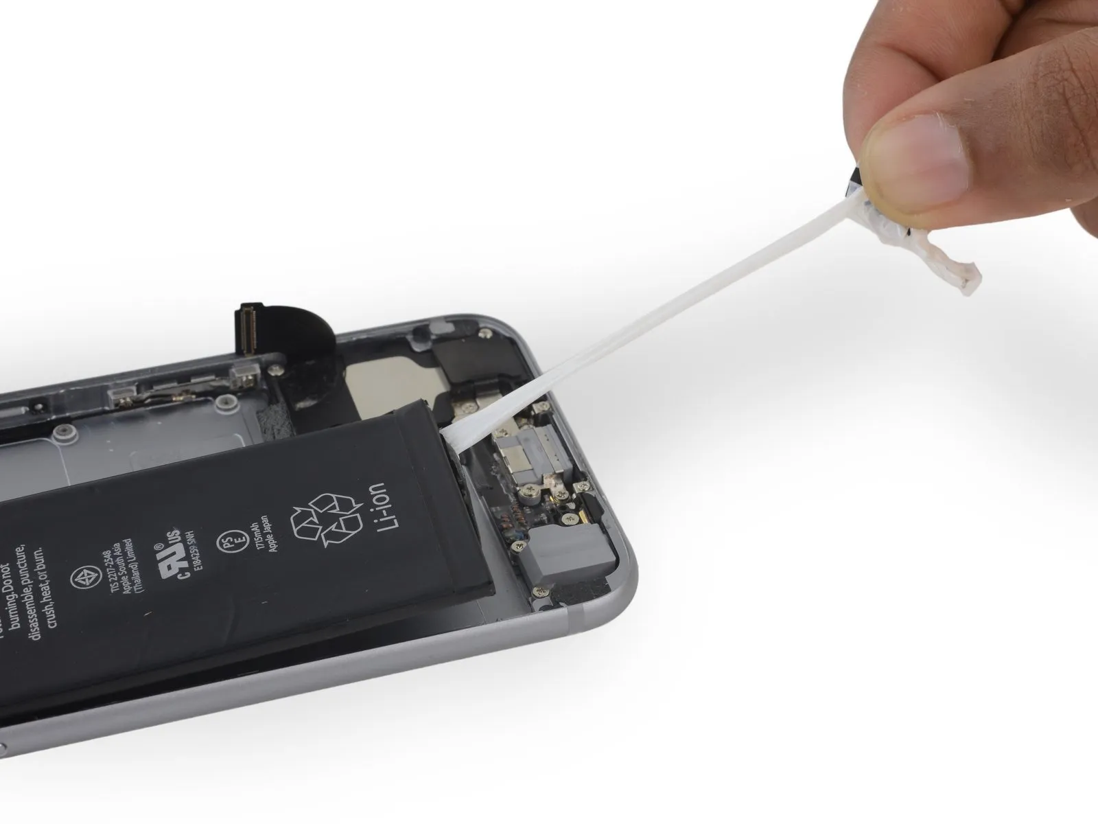
- Maintain traction and draw steadily until the entire strip detaches.
- Should the battery adhesive strips detach during removal, carefully gather any detached portions with your fingers or a tool having a flat, non-piercing edge, and proceed with the pulling action.
- Should a battery adhesive strip tear and become irretrievable during this process, discard the intact strip and proceed directly to Step 48.
Step 50

- Apply the same procedure to install the second adhesive strip.
- To prevent the battery from being ejected from the device during strip removal, maintain firm pressure on the battery with one hand while detaching the second strip, as its release could cause the battery to become dislodged.
Step 51
Having detached the three adhesive strips without issue, proceed to the subsequent procedure.
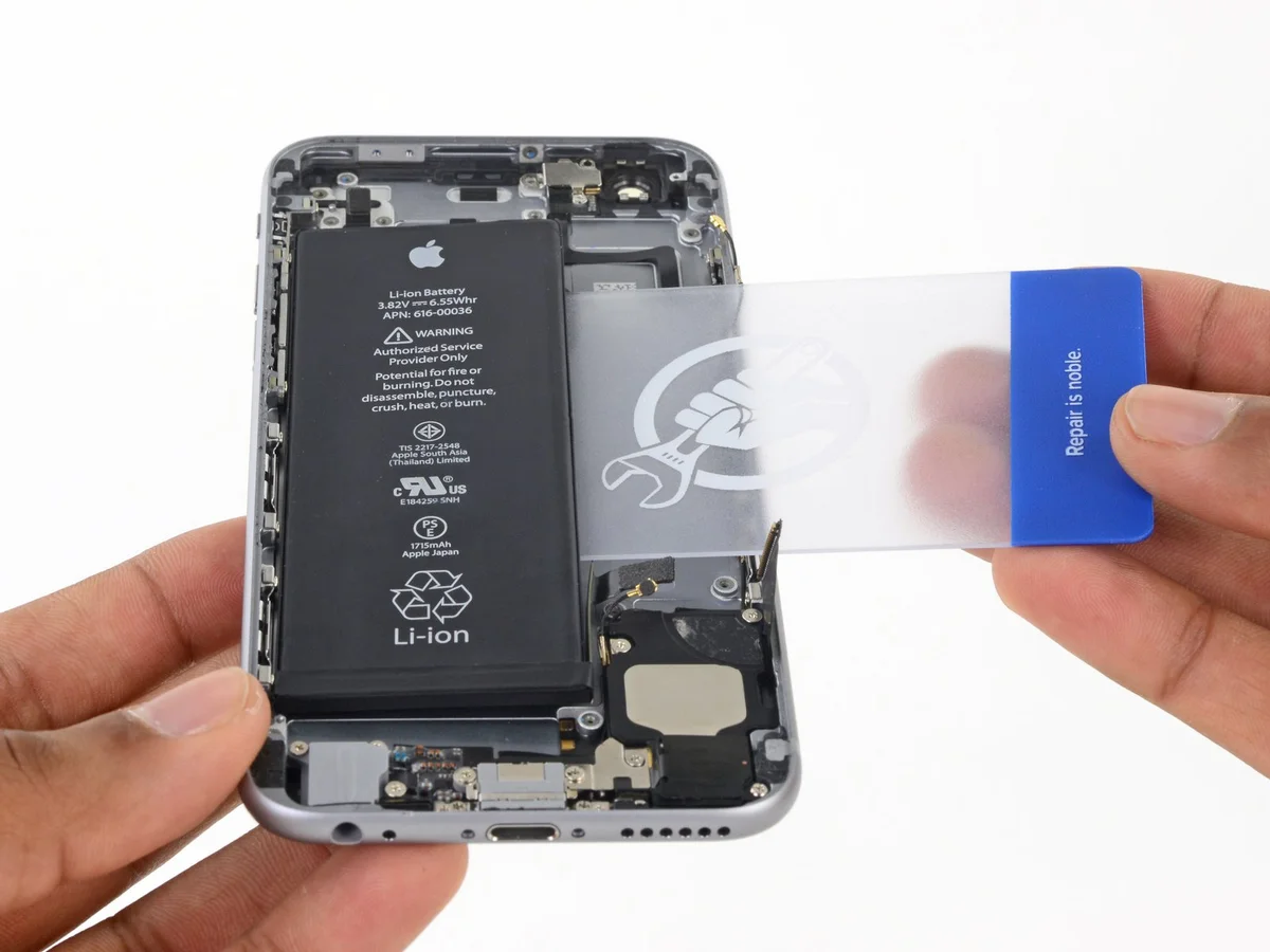
If the battery does not release, carefully use a prying tool to separate it from the rear case.
Allow approximately one minute to pass, then turn the device over and carefully slide a plastic card between the battery and the phone casing to separate any lingering adhesive.
If the battery does not release, carefully use a prying tool to separate it from the rear case.
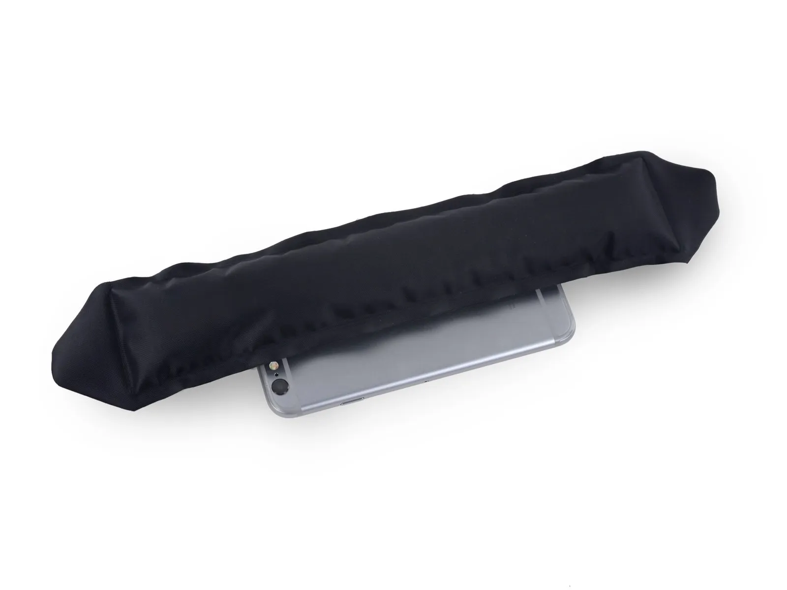
- Using an iOpener, heat the rear case's exterior surface, positioned directly above the battery.
- To soften the adhesive, direct warm air from a heat gun or hair dryer onto the area.
Allow approximately one minute to pass, then turn the device over and carefully slide a plastic card between the battery and the phone casing to separate any lingering adhesive.
Step 52
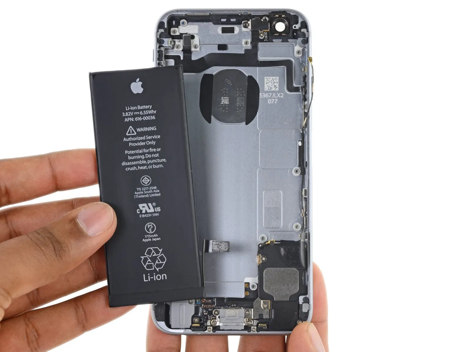
Disconnect the power source by detaching the battery.
To ensure proper battery installation, follow the procedures outlined in this guide for replacing the adhesive strips securing the battery.
To ensure proper battery installation, follow the procedures outlined in this guide for replacing the adhesive strips securing the battery.
Step 53

Using a Phillips screwdriver, detach the flash bracket by unscrewing the 1.3 mm screw that holds it in place.
Carefully detach the flash bracket.
Carefully detach the flash bracket.
Step 54
Carefully pry the flash unit from its rear case opening using the flat spudger tip.
Step 55


Using a Phillips screwdriver, detach the five screws.
Excessive tightening of these screws when putting the device back together can impair the functionality of the power and volume buttons, preventing them from clicking as intended.
Verify that each button exhibits the expected tactile click during operation prior to proceeding with reassembly.
- The left side of the rear case secures with two screws, each measuring 2.5 mm.
- A Phillips #000 screwdriver is needed to secure a 2.1 mm screw located on the left side of the rear case.
- Secure the rear case to the right edge using two screws, each measuring 2.1 mm.
Excessive tightening of these screws when putting the device back together can impair the functionality of the power and volume buttons, preventing them from clicking as intended.
Verify that each button exhibits the expected tactile click during operation prior to proceeding with reassembly.
Step 56
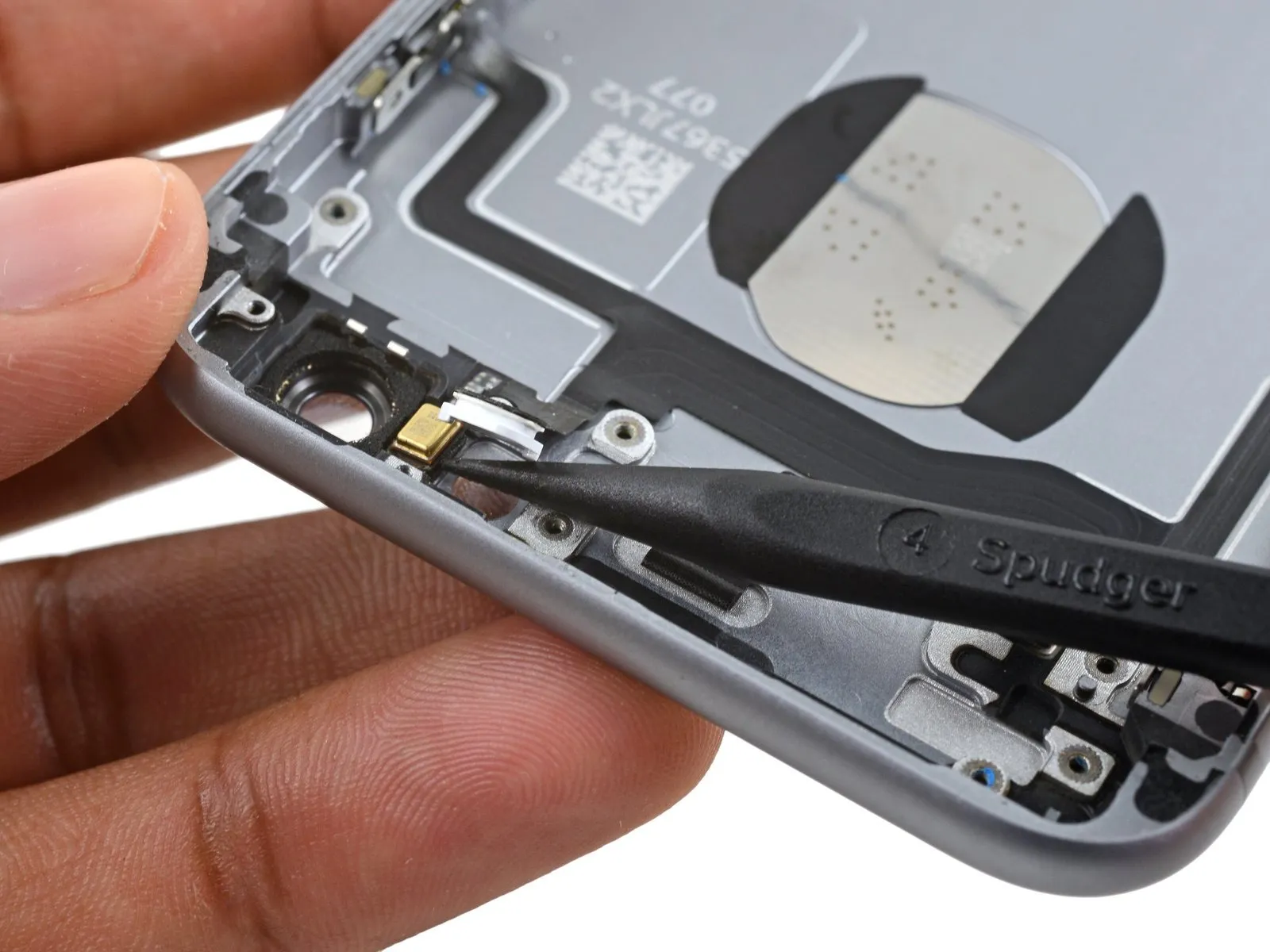

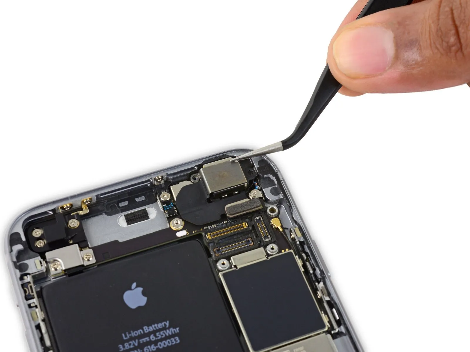
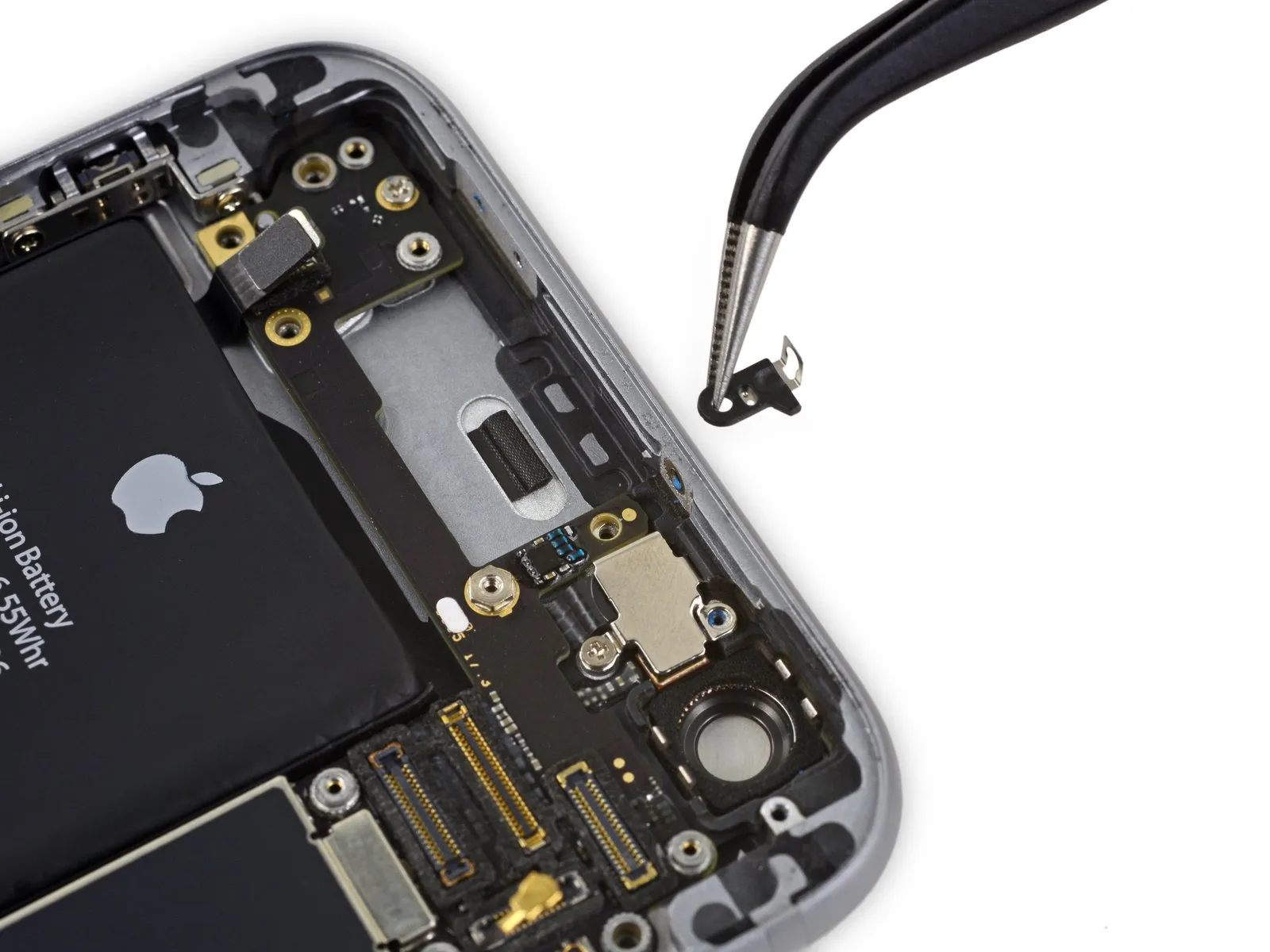
Carefully detach the microphone assembly from the back cover by using the tip of a spudger to pry it loose.
Step 57

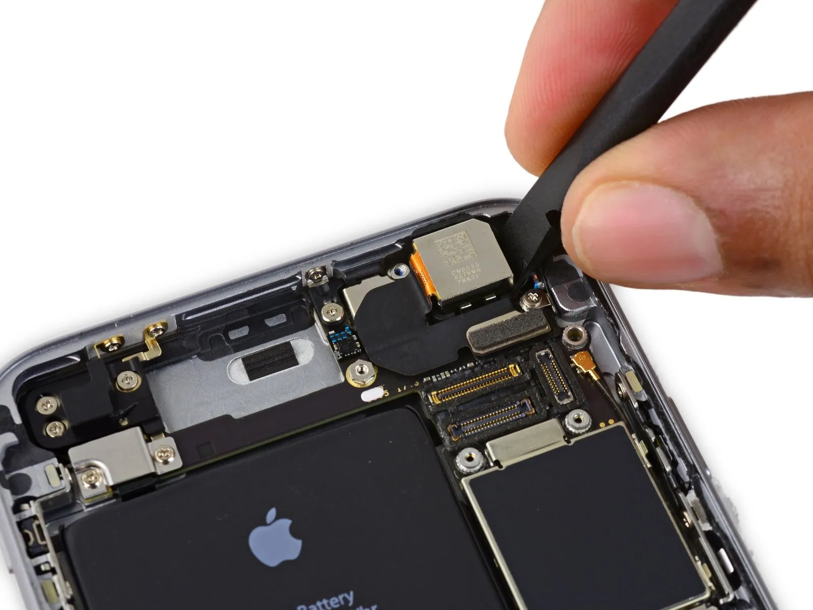
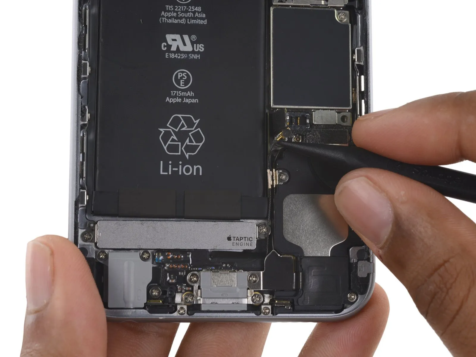
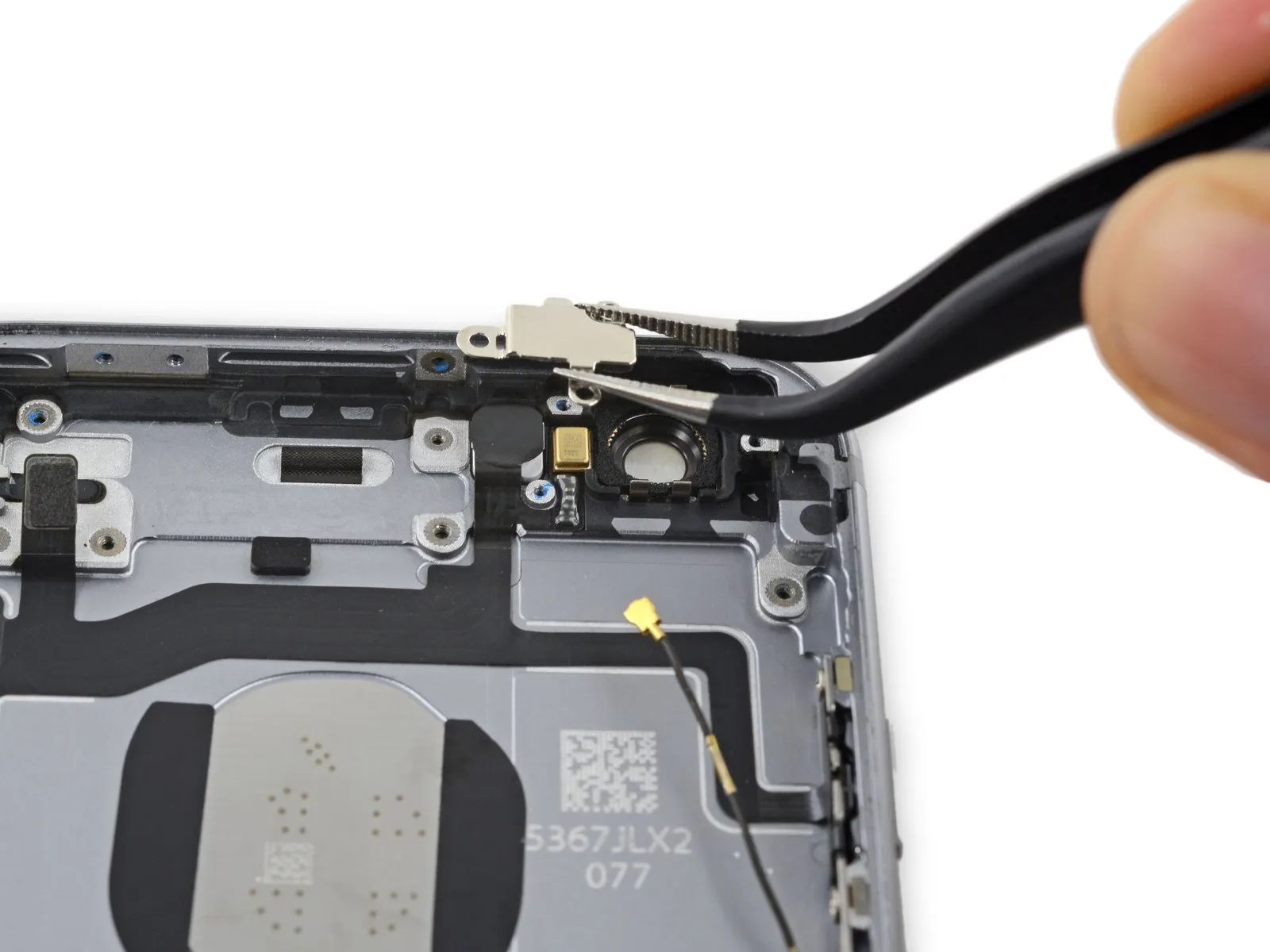
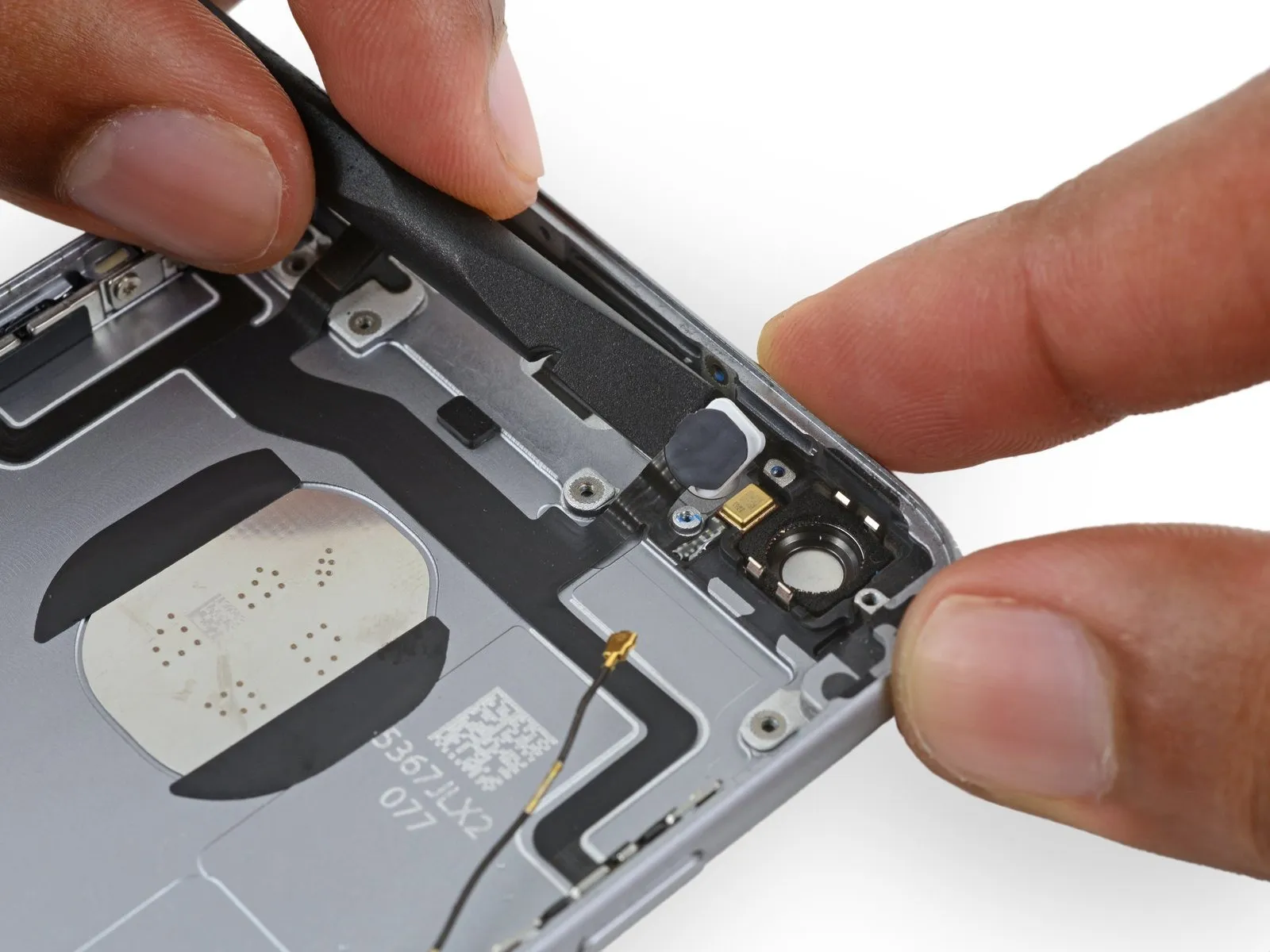
Using a specialized opening tool, carefully insert it into the gap located between the cable connected to the upper assembly and the back housing.
Carefully detach the cable from the back panel.
Carefully detach the cable from the back panel.
Step 58

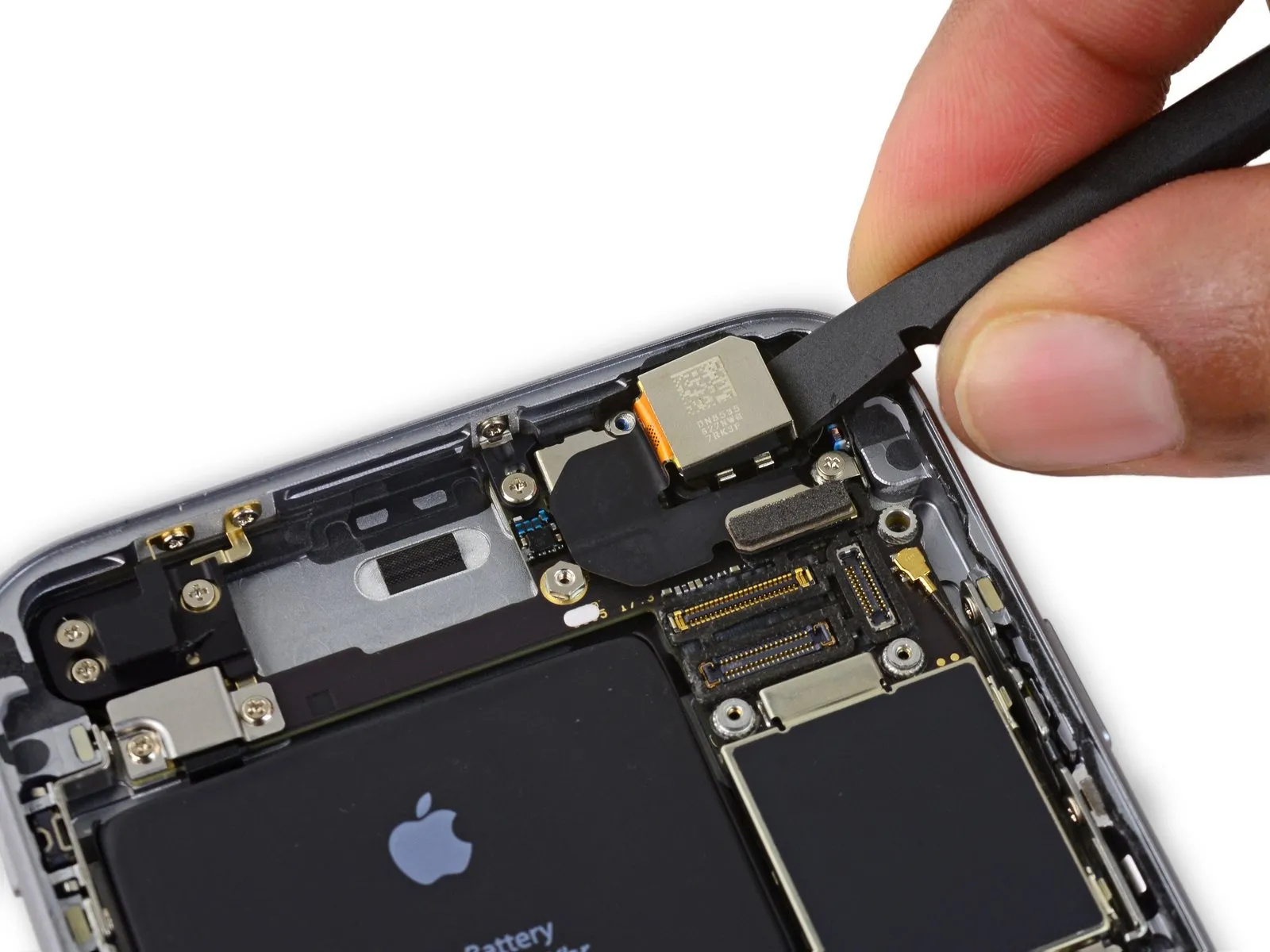
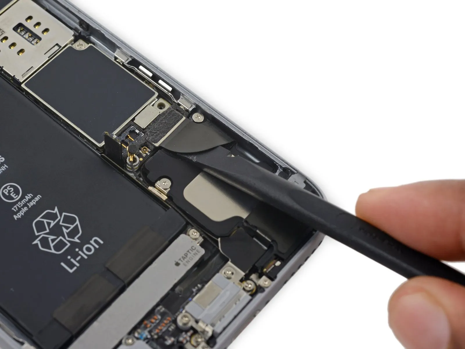
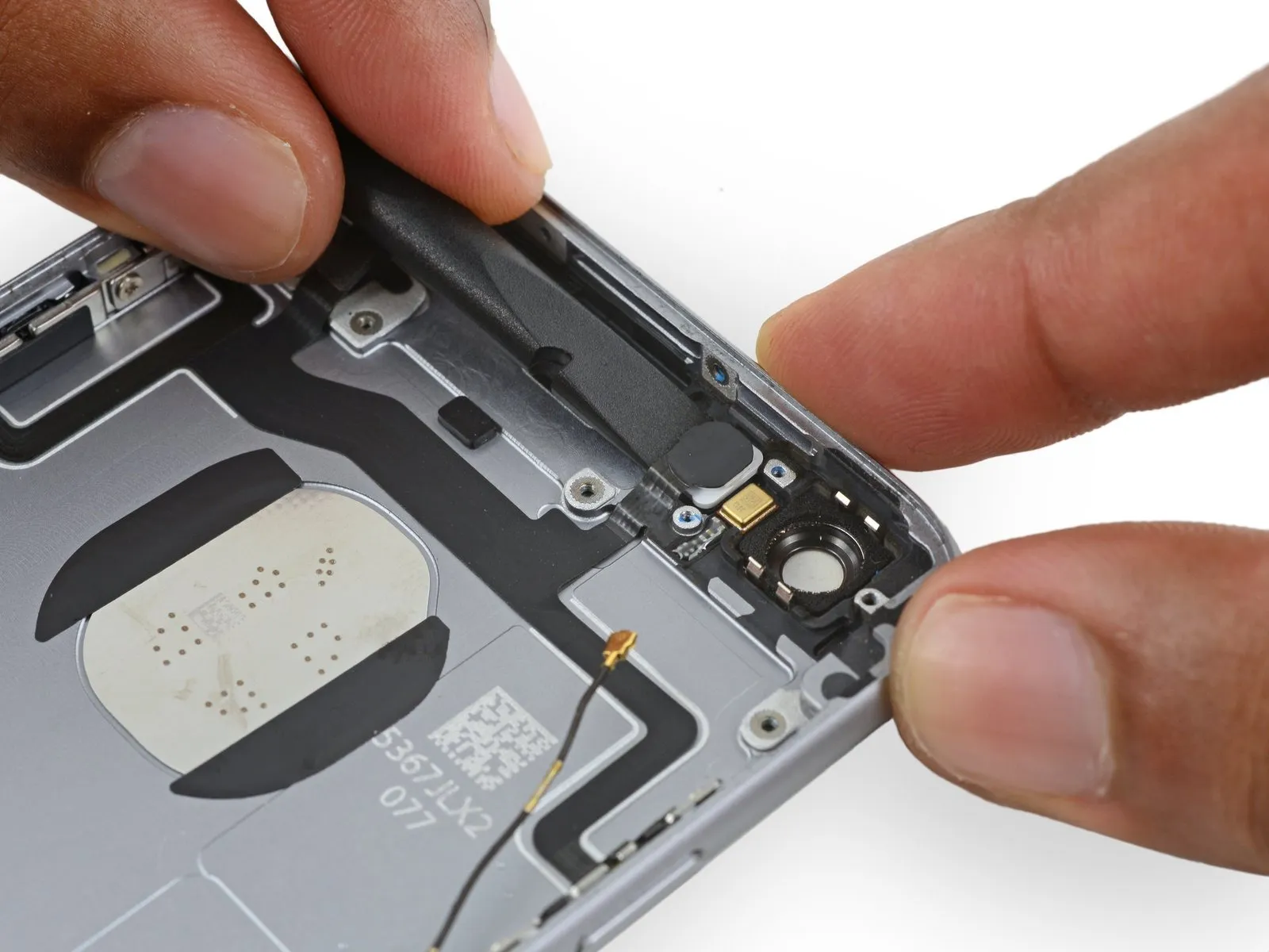
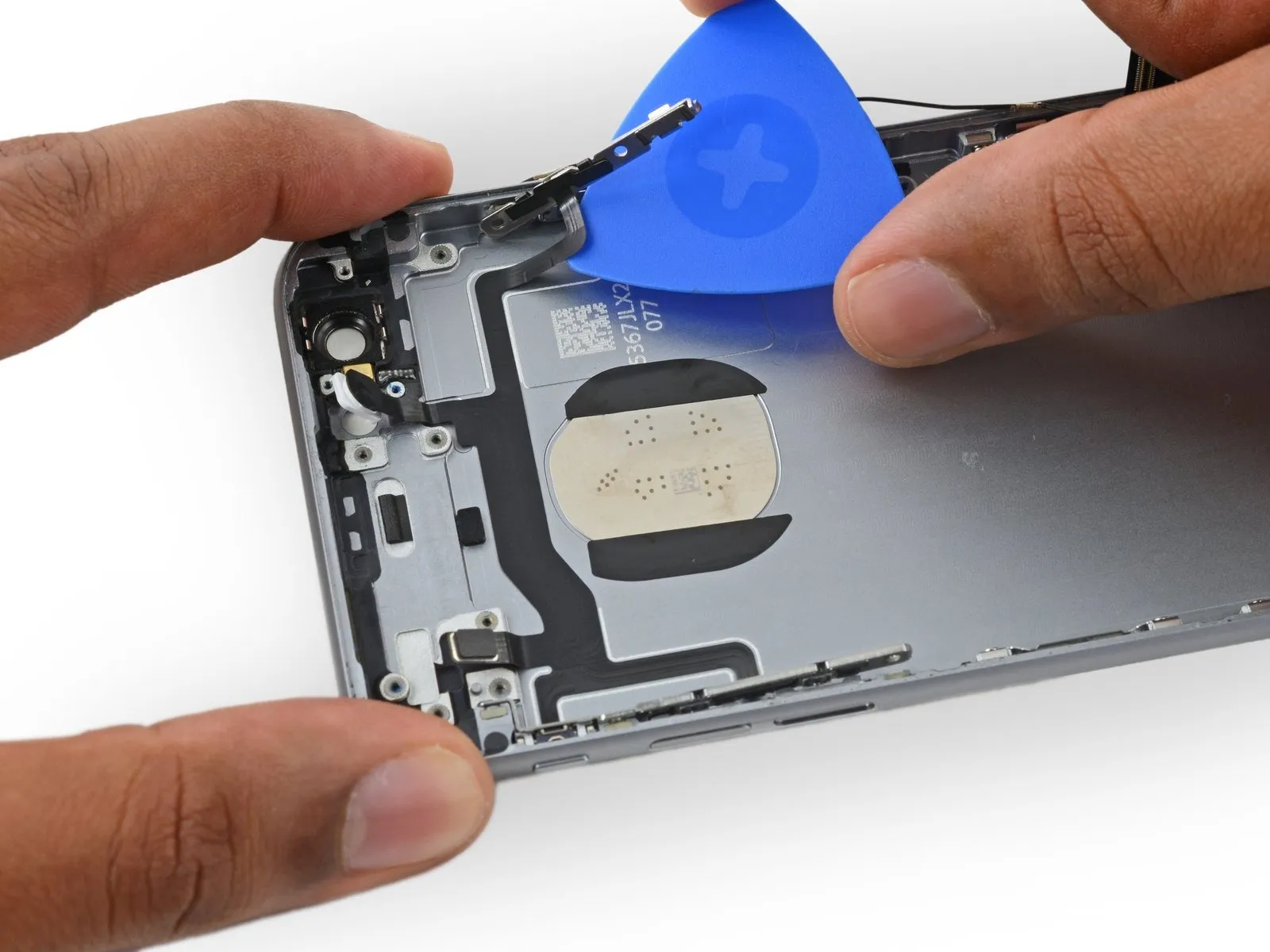
Using the opening pick, advance it beneath the cable, ensuring complete detachment from the rear case.
Step 59
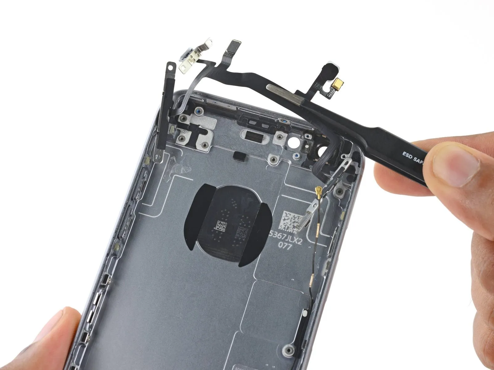
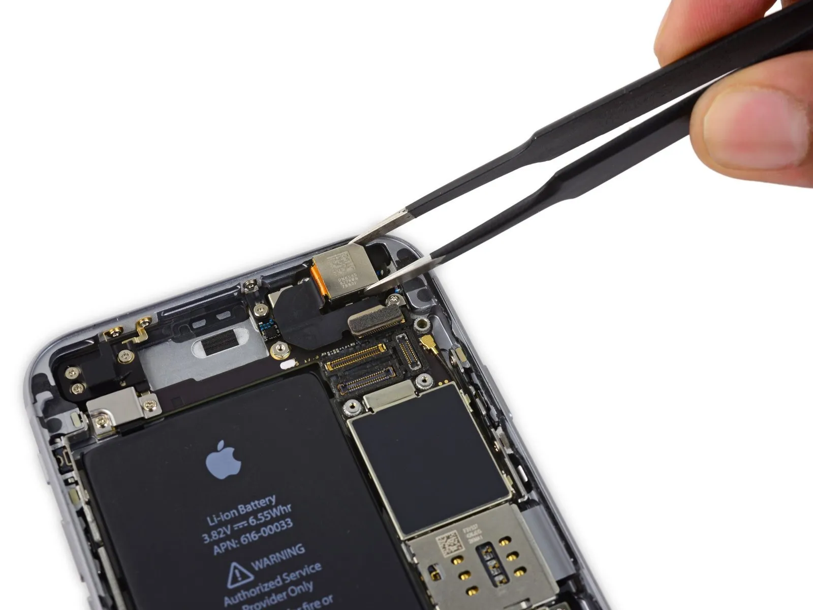
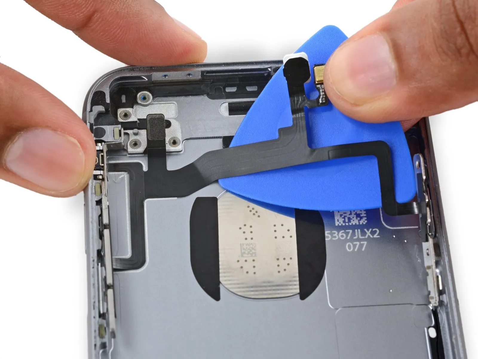
Disconnect the cable harness connecting to the upper assembly.
Step 60
Carefully detach the existing switch cover and move it to the new component if the replacement part lacks one.
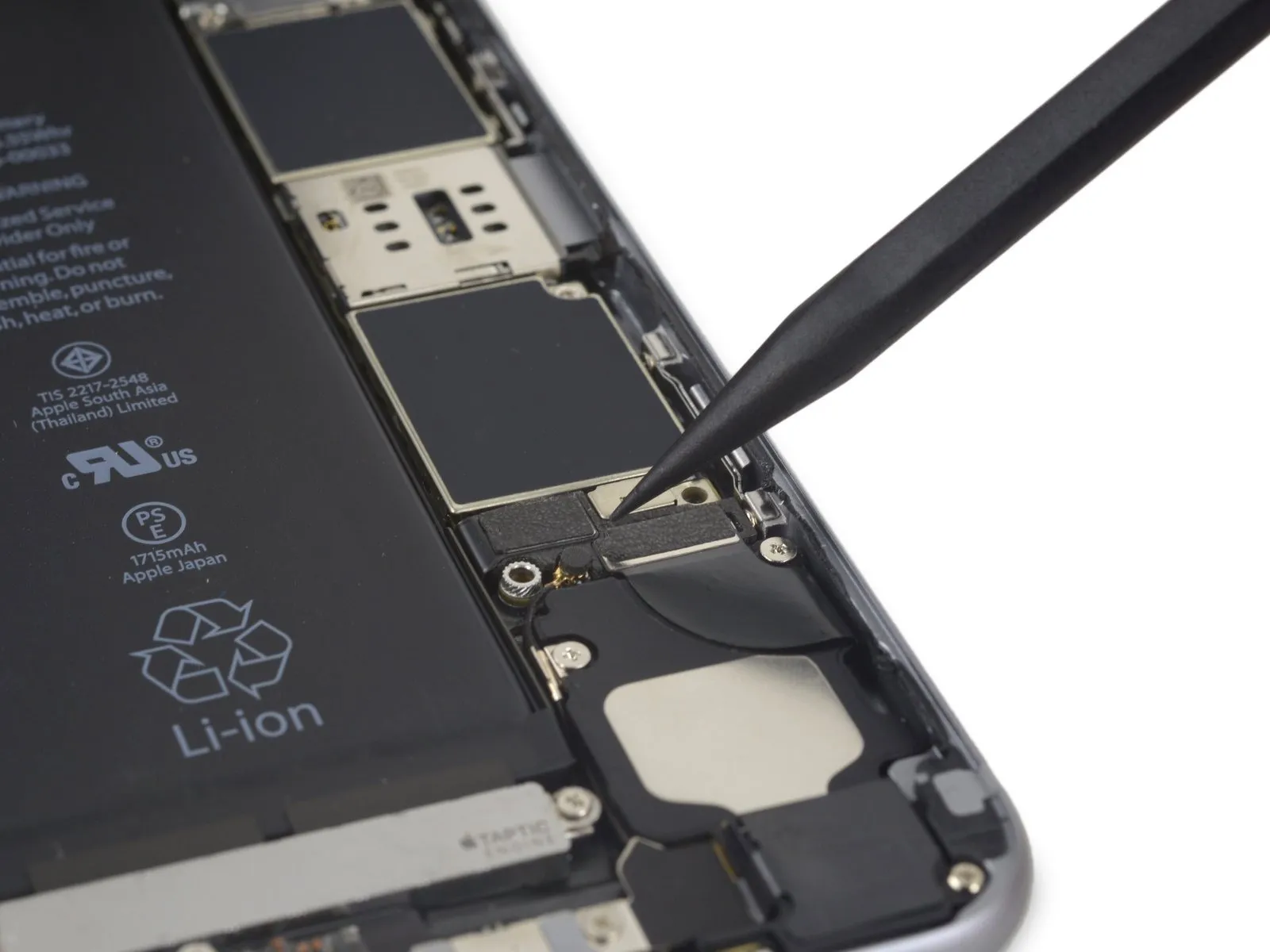
Apply firm, consistent pressure to the existing bracket using the spudger's flat end to secure it.
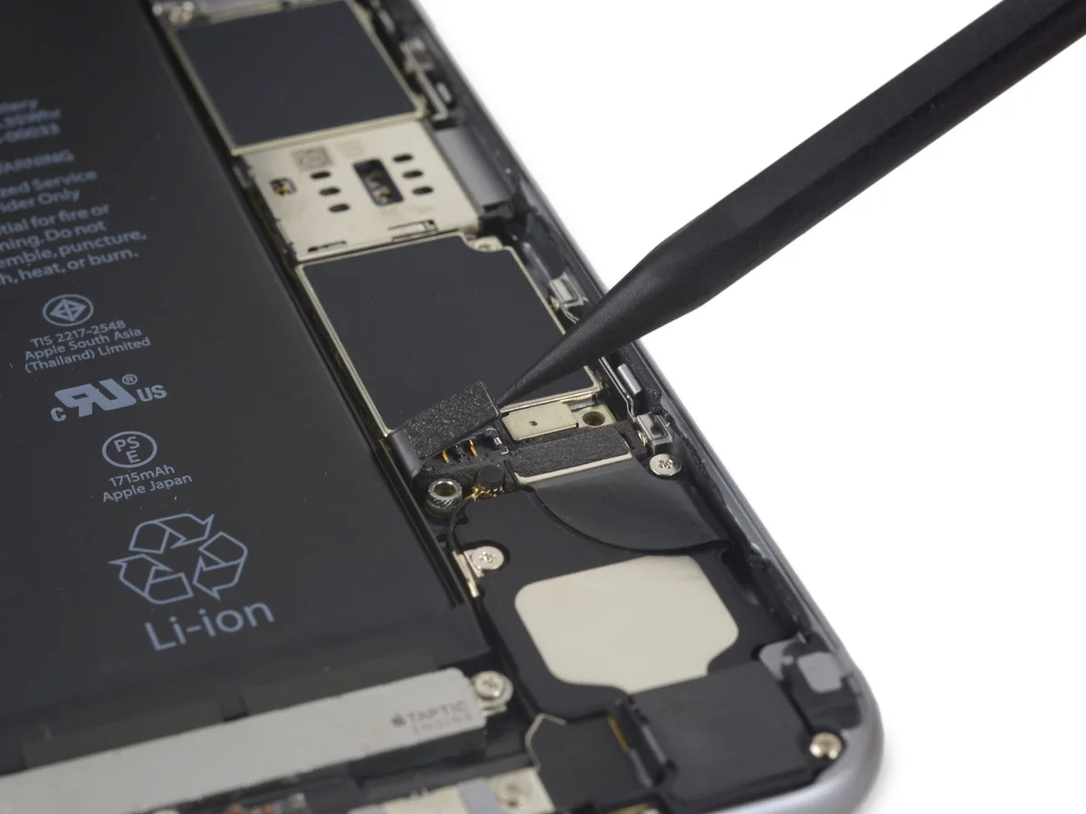
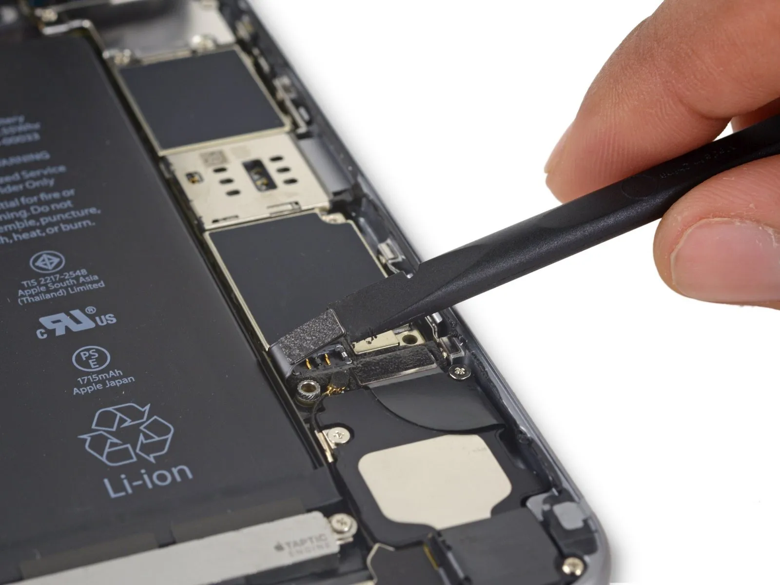
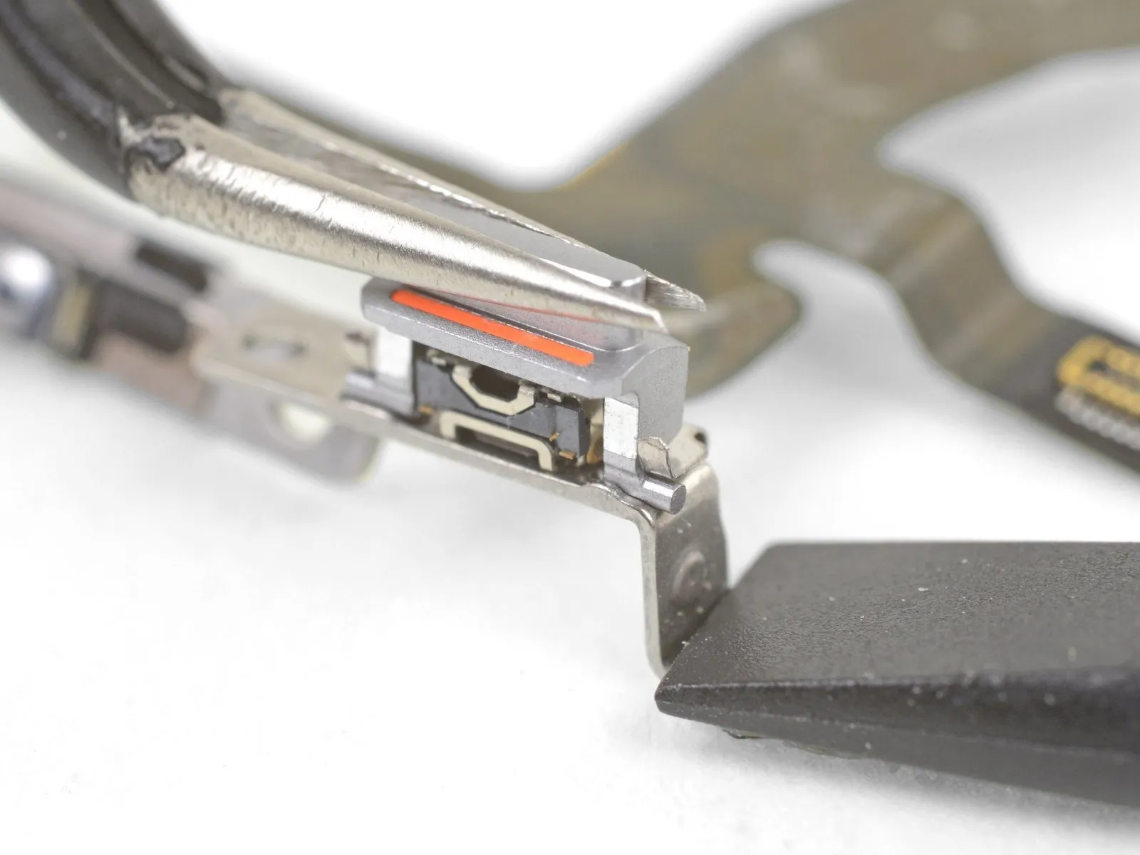
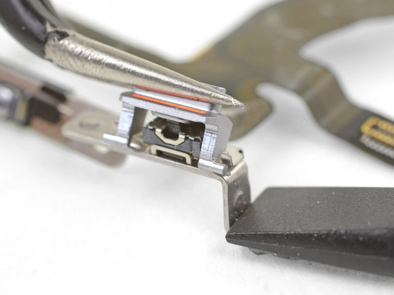
Gently maneuver the switch cover by applying slight rocking pressure with tweezers or your fingers, allowing the retaining clips to release the switch cover pins.
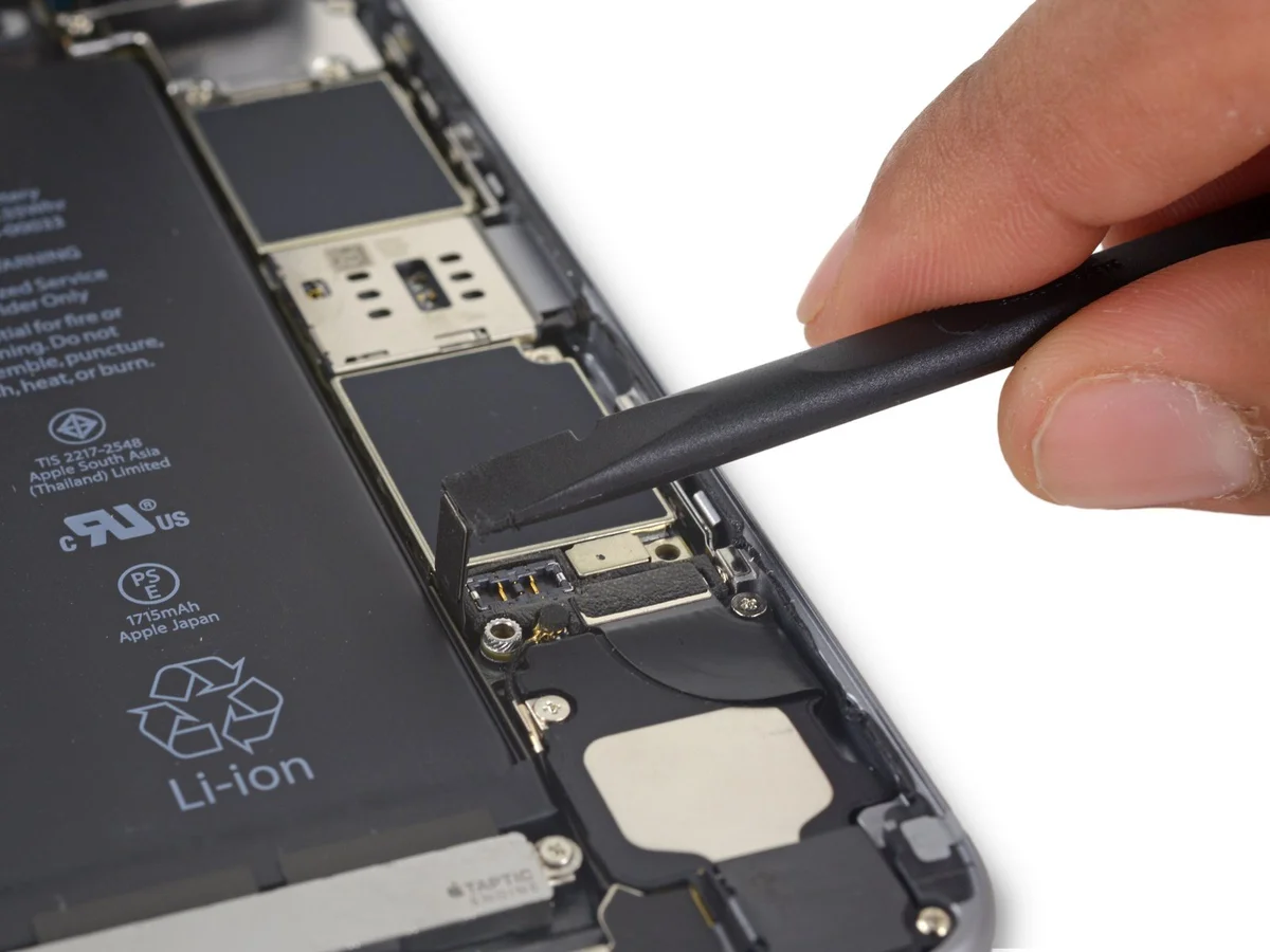
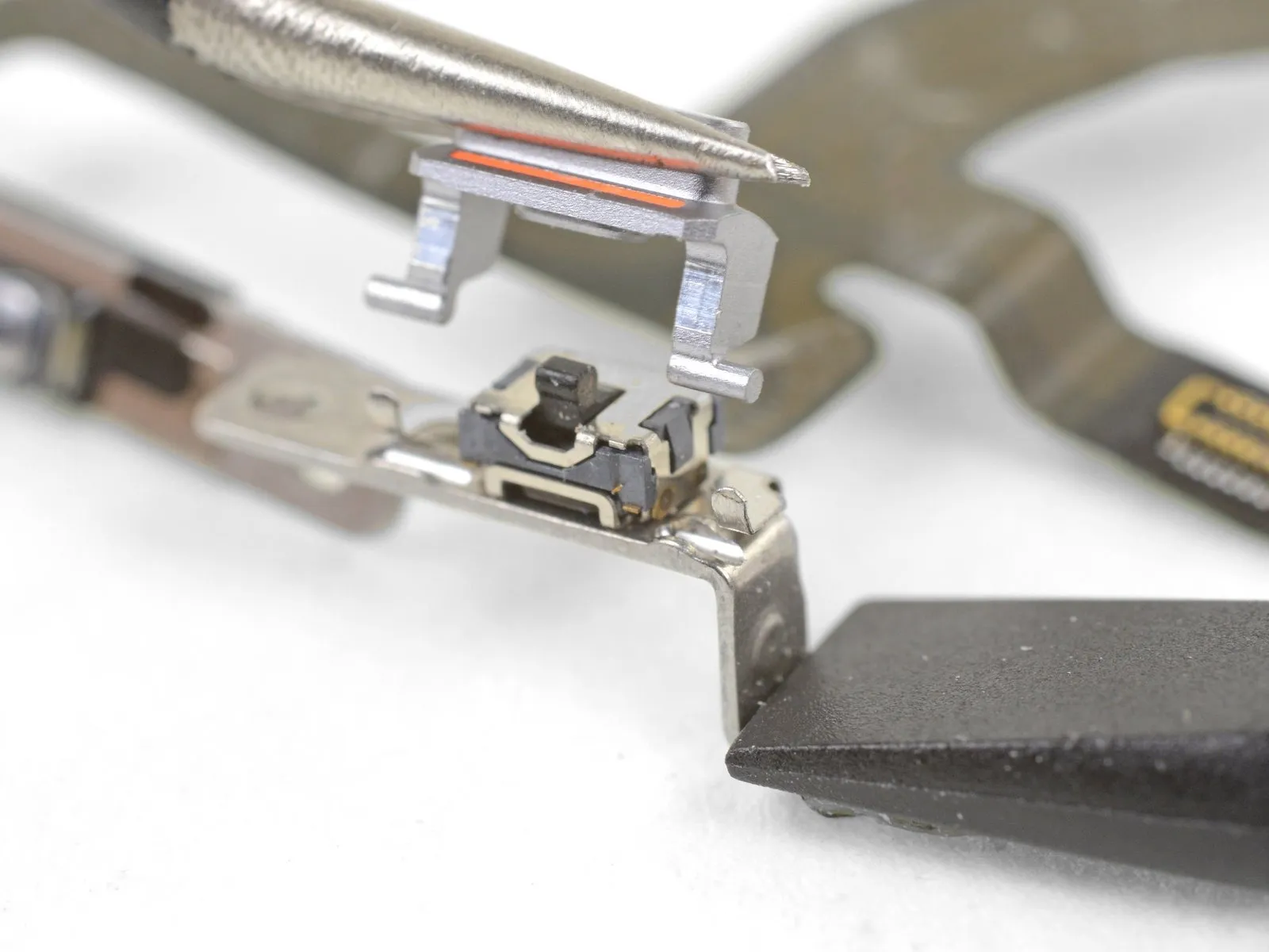
Gently raise the switch cover vertically.
Reassemble the upper cable assembly with the mute switch cover by performing the previous disassembly actions in reverse order.
Ensure the pins are positioned close to the clip openings, avoiding any forceful insertion into the clips. Reattaching the bracket to the case with screws will properly secure the switch cover.
Ensure the switch cover is correctly aligned during installation, as it's designed for a single fit; if encountering difficulty, reposition the switch by moving the black lever to an alternate setting.
Verify the functionality of each switch and button by manually testing their physical operation.
Apply firm, consistent pressure to the existing bracket using the spudger's flat end to secure it.
Gently maneuver the switch cover by applying slight rocking pressure with tweezers or your fingers, allowing the retaining clips to release the switch cover pins.
Gently raise the switch cover vertically.
Reassemble the upper cable assembly with the mute switch cover by performing the previous disassembly actions in reverse order.
Ensure the pins are positioned close to the clip openings, avoiding any forceful insertion into the clips. Reattaching the bracket to the case with screws will properly secure the switch cover.
Ensure the switch cover is correctly aligned during installation, as it's designed for a single fit; if encountering difficulty, reposition the switch by moving the black lever to an alternate setting.
Verify the functionality of each switch and button by manually testing their physical operation.
Step 61 | Volume Control Button Covers

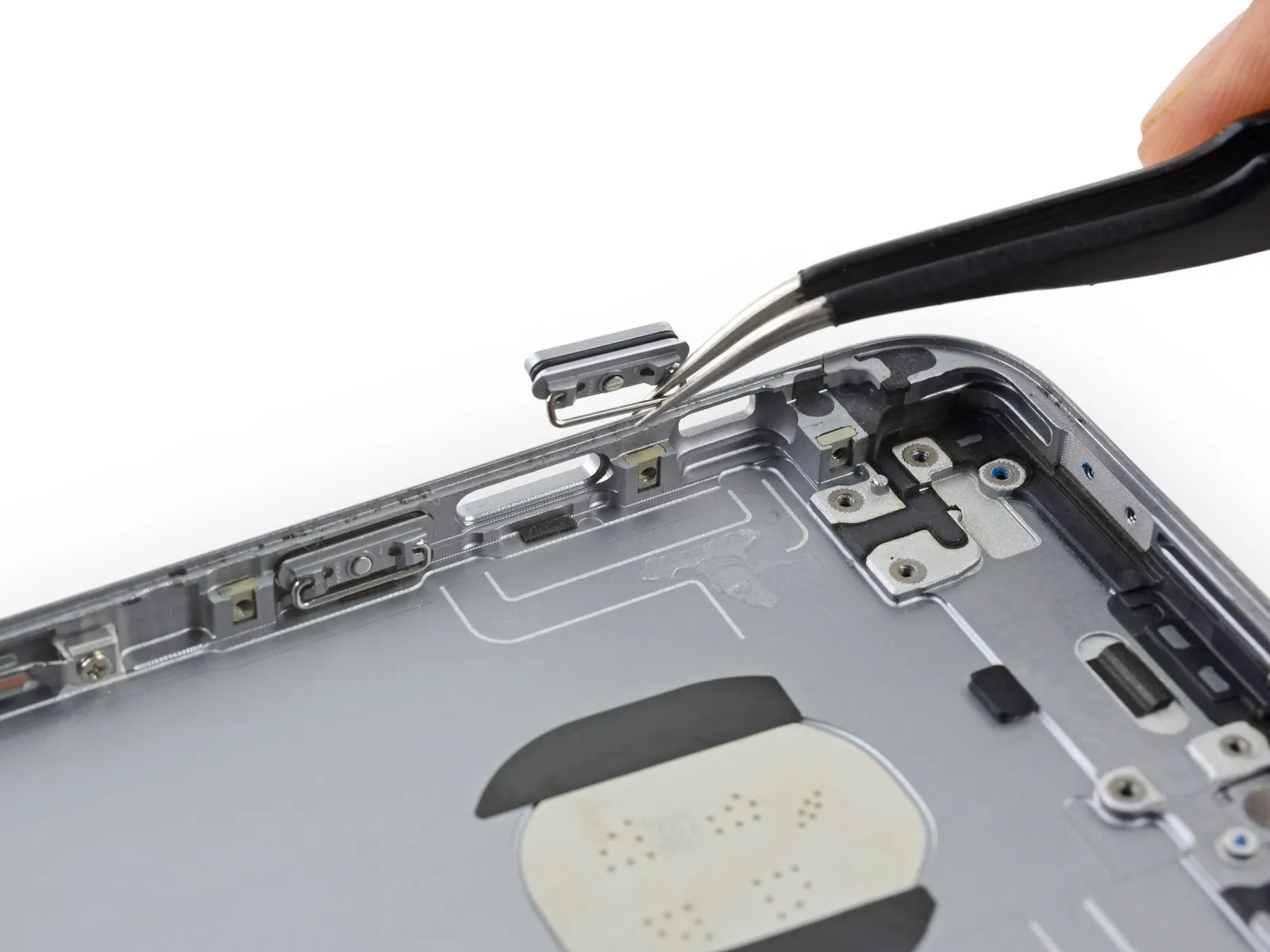
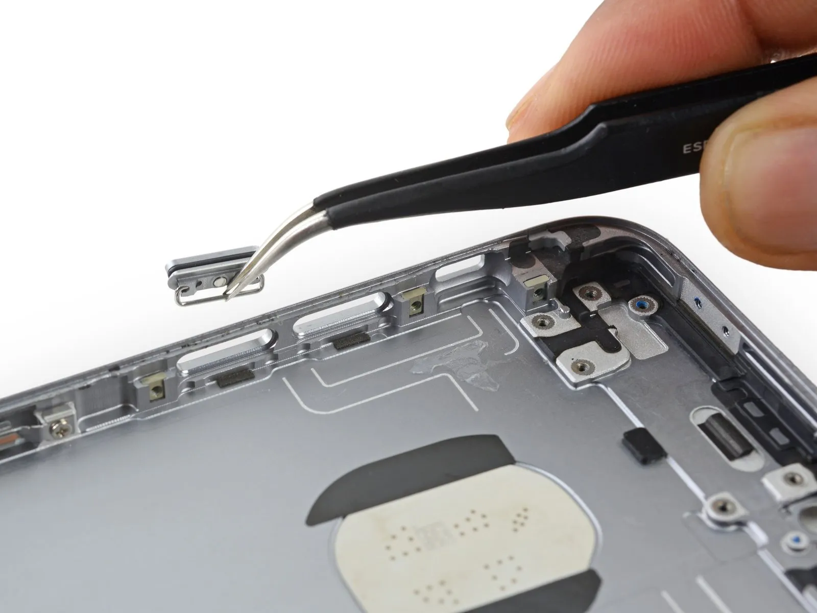
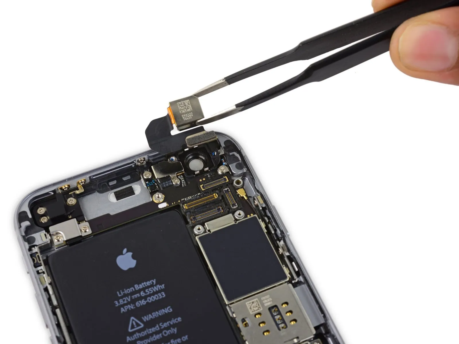
Using your fingers, carefully extract the volume control button cover by gripping the metal bar located behind it, pulling the cover away from its mounting within the rear case.
Perform the same procedure on the cover for the second volume control button.
Ensure the button covers are correctly positioned during reassembly; the internal metal bar must be angled downwards, aligning with the iPhone's rear enclosure.
Perform the same procedure on the cover for the second volume control button.
Ensure the button covers are correctly positioned during reassembly; the internal metal bar must be angled downwards, aligning with the iPhone's rear enclosure.