iPhone 6s Plus Battery Replacement
Employ this manual to restore functionality to your iPhone 6s PlusWhen the battery exhibits swelling, exercise necessary safety measures.
- The following instructions detail the separation of the front panel assembly, a step designed to safeguard the delicate display cable connections.
- Should you possess the skill to cautiously support the display while extracting the battery from the iPhone, you may bypass the display removal process and proceed directly to the battery replacement steps.
- Additionally, this guide outlines the removal of the Taptic Engine; this step is not essential but is suggested to facilitate the separation of the battery's adhesive.
To ensure peak battery efficiency, after finishing this procedure, perform a calibration on your replacement battery: Initially charge it to full capacity, maintaining the charge for a minimum of two additional hours. Subsequently, deplete the battery completely through normal usage until the device powers down. Finally, recharge the device uninterrupted until it reaches 100% capacity.
This procedure can also be utilized to replace the battery connector bracket.
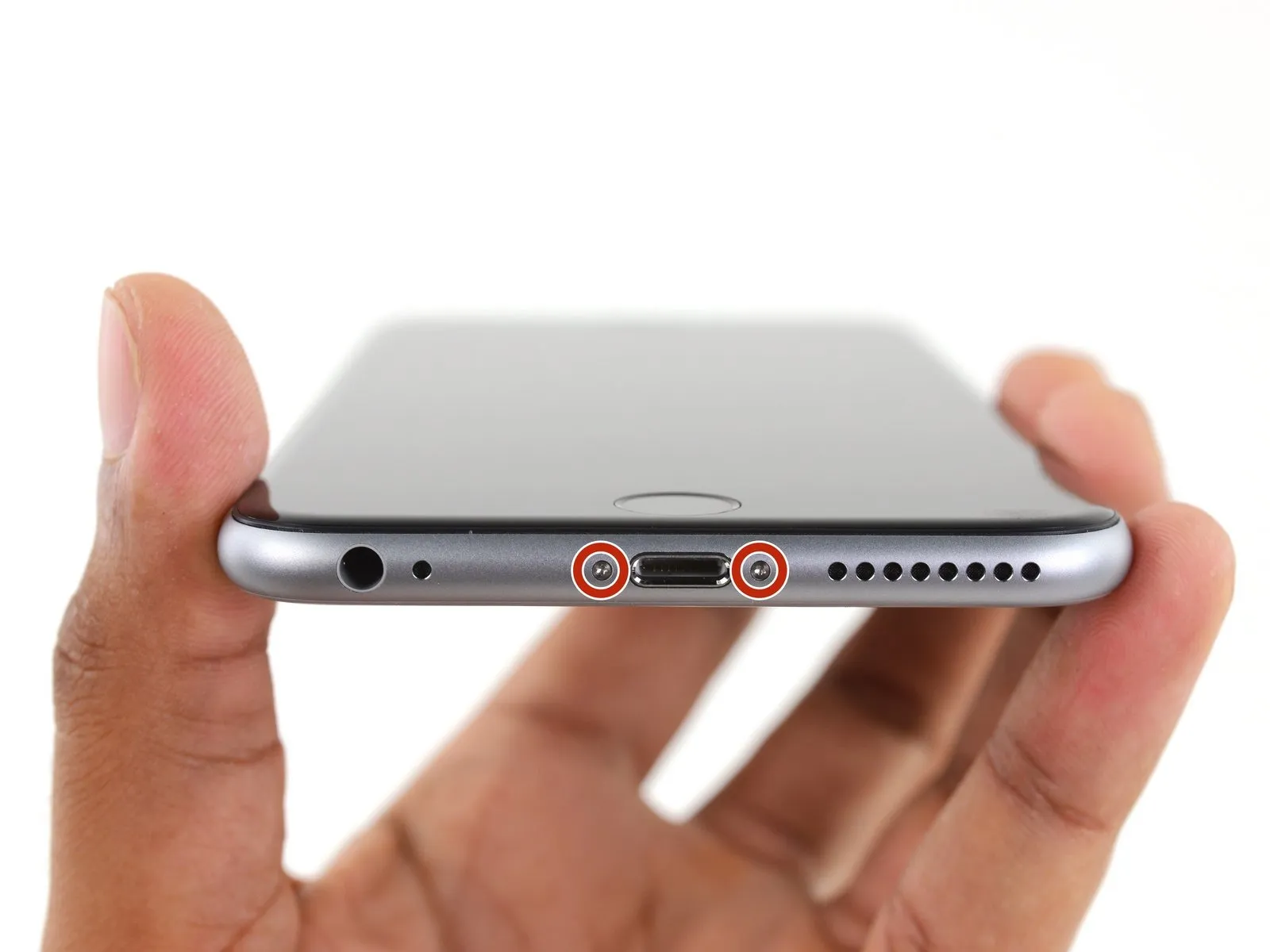
Step 1 | Pentalobe Screws
- To prevent potential hazards, ensure your iPhone's battery level is reduced to less than 25% prior to commencing any disassembly procedures.A fully charged lithium-ion batteryposes a significant fire and/or explosion risk if it sustains accidental damage, such as a puncture.
- Deactivate your iPhone by powering it down completely before starting the disassembly process.
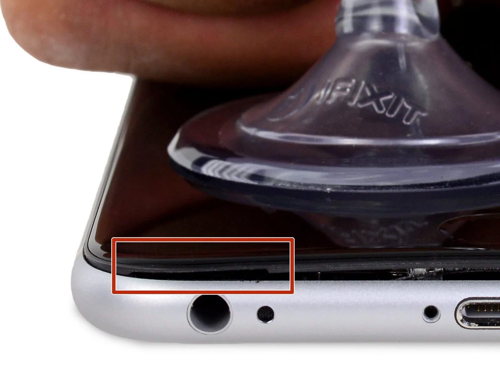
- Begin the disassembly by eliminating the pair of 3.4 mm Pentalobe screws located on both sides of the Lightning connector.
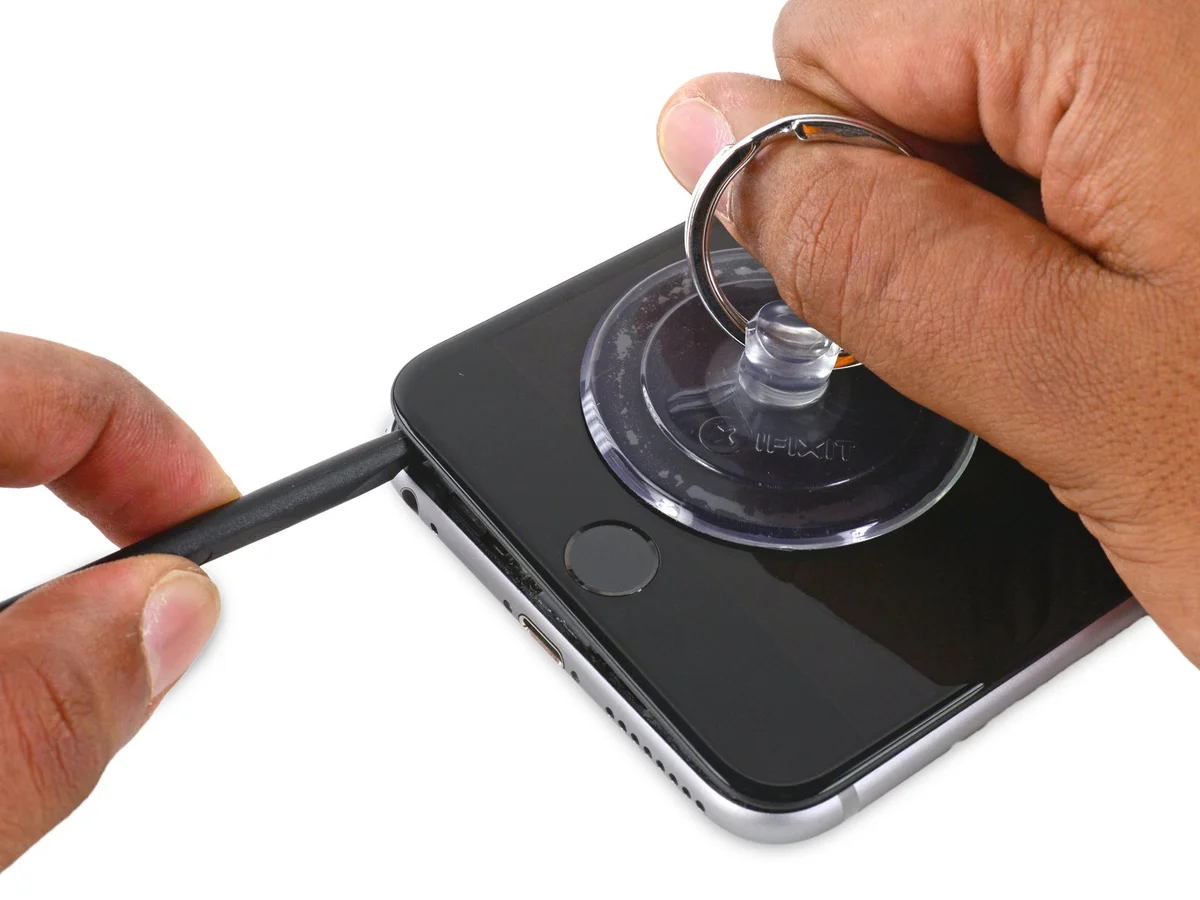
Step 2 | Anti-Clamp instructions


- The following two procedures illustrate the function of the Anti-Clamp, a specialized instrument developed to simplify the initial opening process; should you choose not to utilize this tool, proceed to the instructions three steps further down.
- Detailed guidance regarding the operation of the Anti-Clamp, is available in a separate instructional document.
- To release the locking mechanism, draw the blue handle towards the rear.
- Carefully position the arms across either the left or right side of the iPhone’s frame.
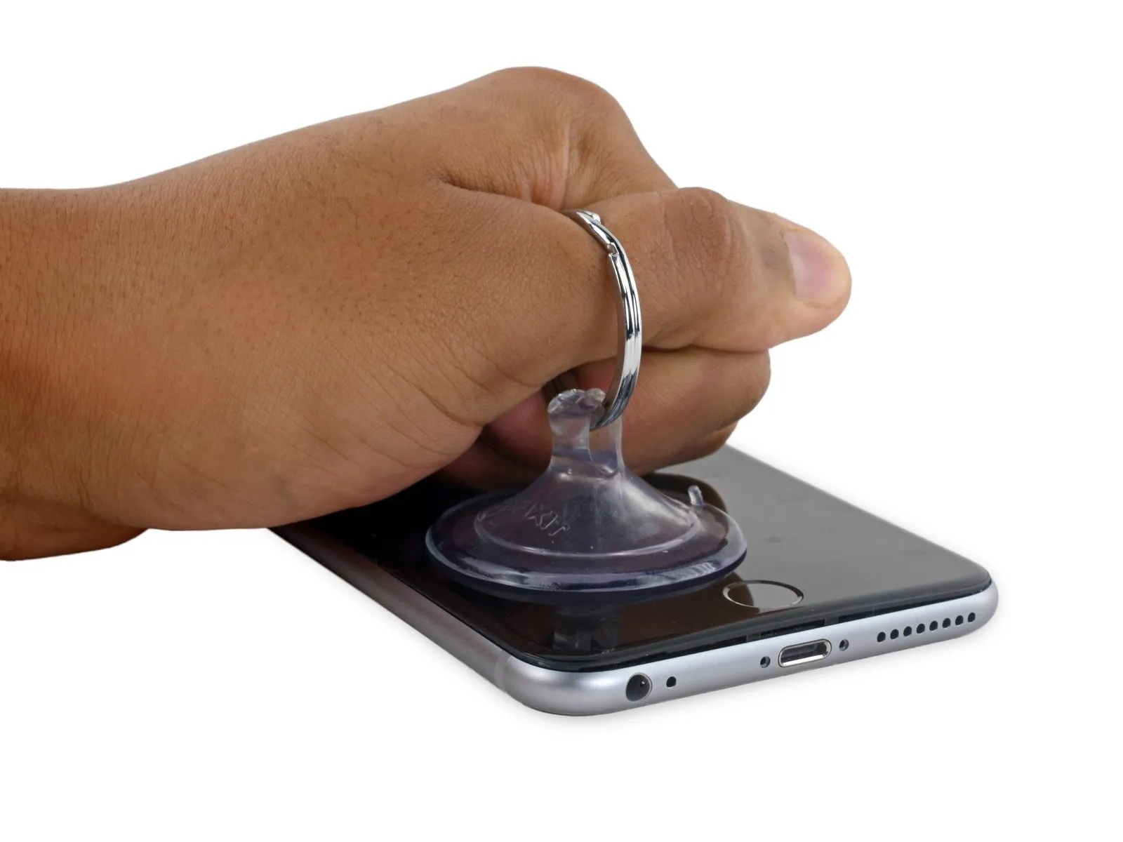
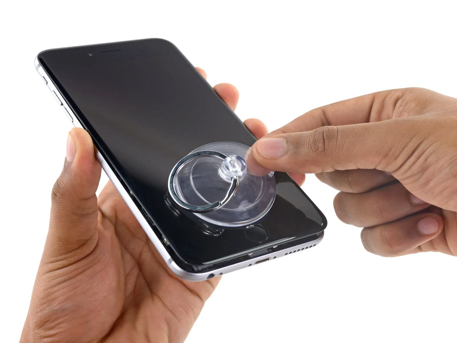
- Place the suction cups close to the lower edge of the iPhone, situated directly above the home button—one on the front surface and one on the rear.
- Apply pressure by compressing the cups together to establish a secure suction hold on the intended area.
- Should the iPhone’s surface prove excessively smooth, preventing adequate adhesion by the Anti-Clamp, applying adhesive tape can provide a more textured surface for improved grip.
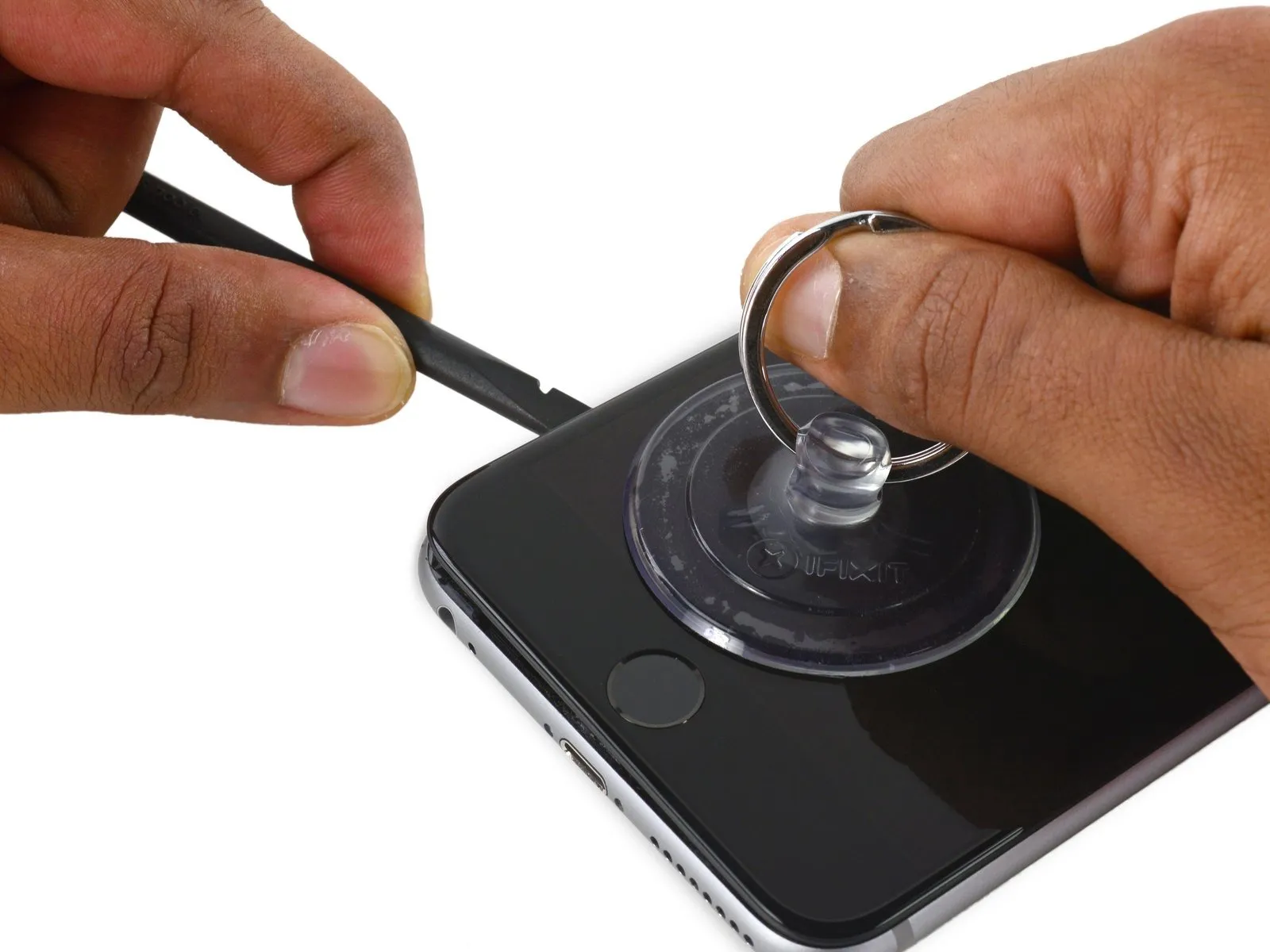
Step 3


- To secure the arms, advance the blue handle in a forward motion.
- Rotate the handle clockwise a full revolution, or until the suction cups begin to deform.
- Maintain the parallel positioning of the suction cups; should they become misaligned, slightly release the suction cups and readjust the arms.
- Introduce an opening pick beneath the display screen once the Anti-Clamp has generated a noticeable separation.
- Should the Anti-Clamp fail to produce an adequate gap, rotate the handle by 90 degrees.
- Avoid rotating the handle beyond a 90-degree increment at any point, and allow several seconds to pass between rotations, permitting the Anti-Clamp and time to facilitate the separation.
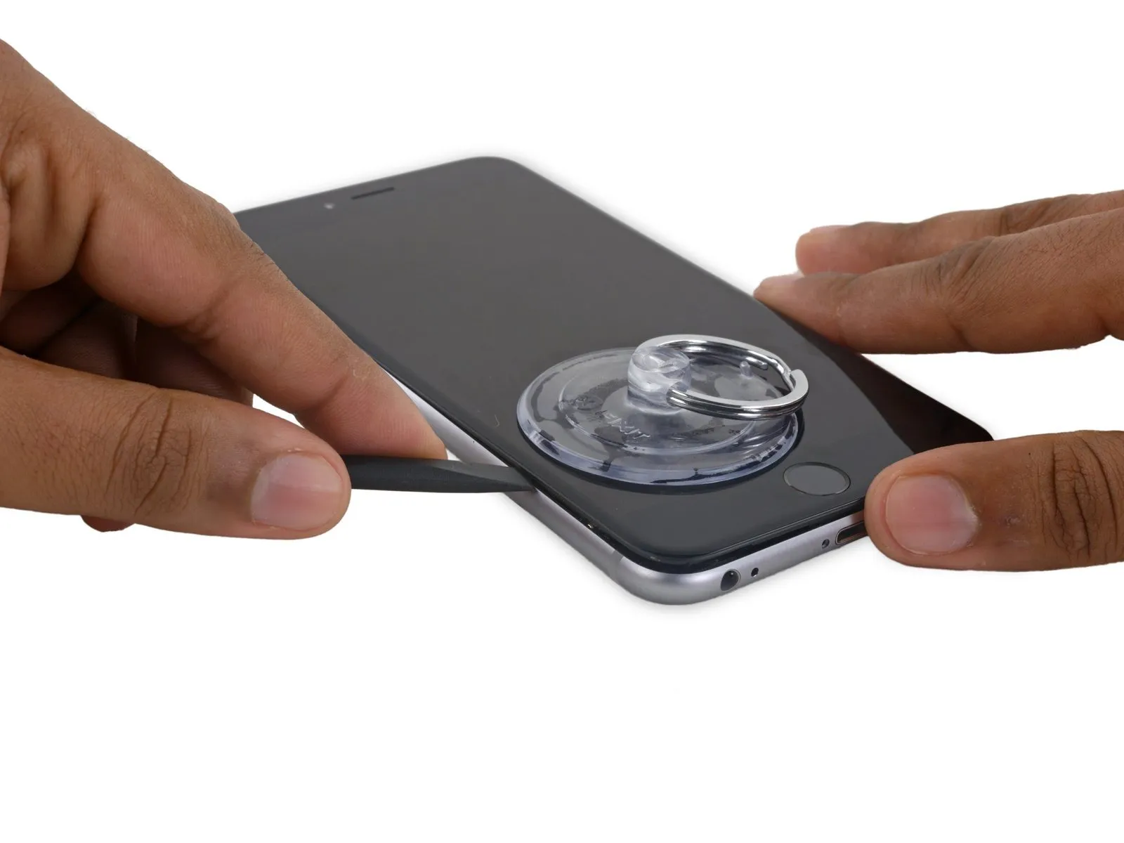
Step 4 | Opening Procedure
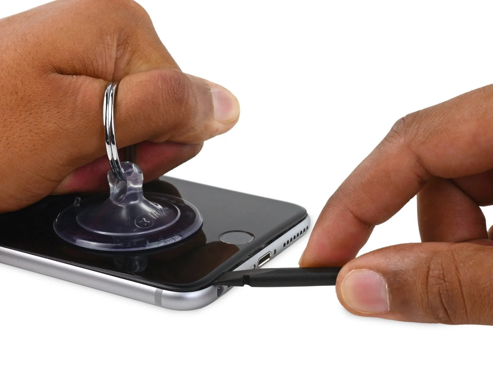
- In the absence of an Anti-Clamp tool, proceed with the subsequent three instructions utilizing a suction handle.Anti-Clamp, follow the next three steps to use a suction handle.
- Introduce gentle warmth to the device's bottom border by employing an iOpener or hair dryer, maintaining the heat for approximately one minute.
- This thermal application loosens the adhesive that holds the display in place, facilitating easier separation.
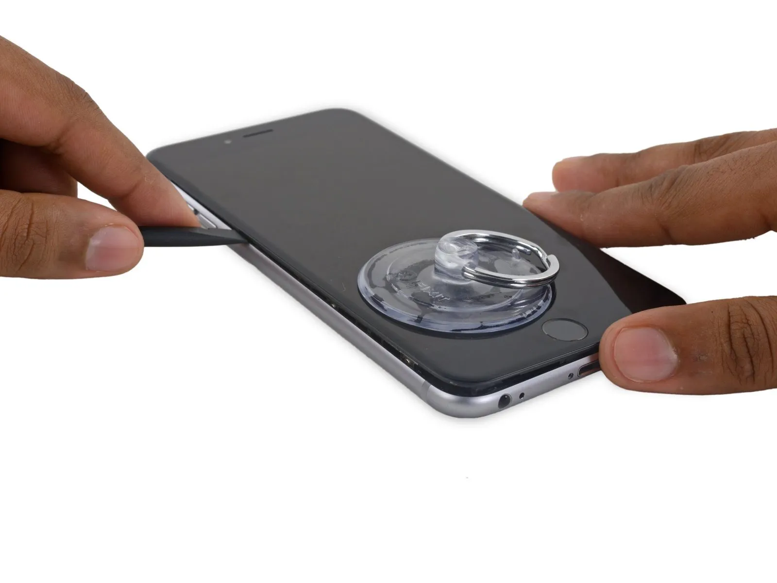
Step 5
- Separating the display from the 6s Plus device involves releasing a delicate adhesive layer that runs along the display's outer edge. To ensure a secure reassembly, prepare replacement adhesive strips if you intend to substitute the original. Successful completion of this repair is achievable without adhesive replacement, and operational performance should remain unaffected.
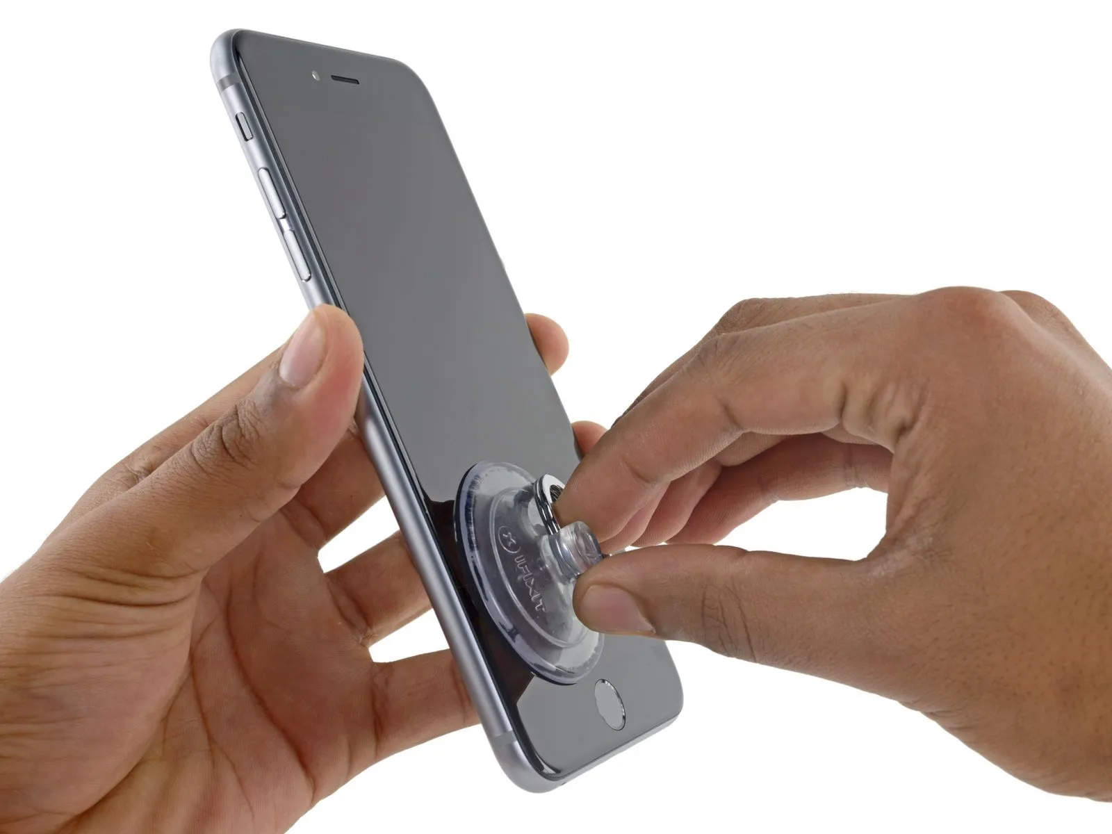
- Securely attach a suction cup to the lower-left portion of the display assembly.
- In cases where the display exhibits severe cracking, applying a sheet of transparent packing tape can improve the suction cup's grip. As an alternative, a robust adhesive tape can be utilized in place of the suction cup. Should these methods prove ineffective, a small amount of superglue can be used to affix the suction cup to the fractured screen.
Step 6
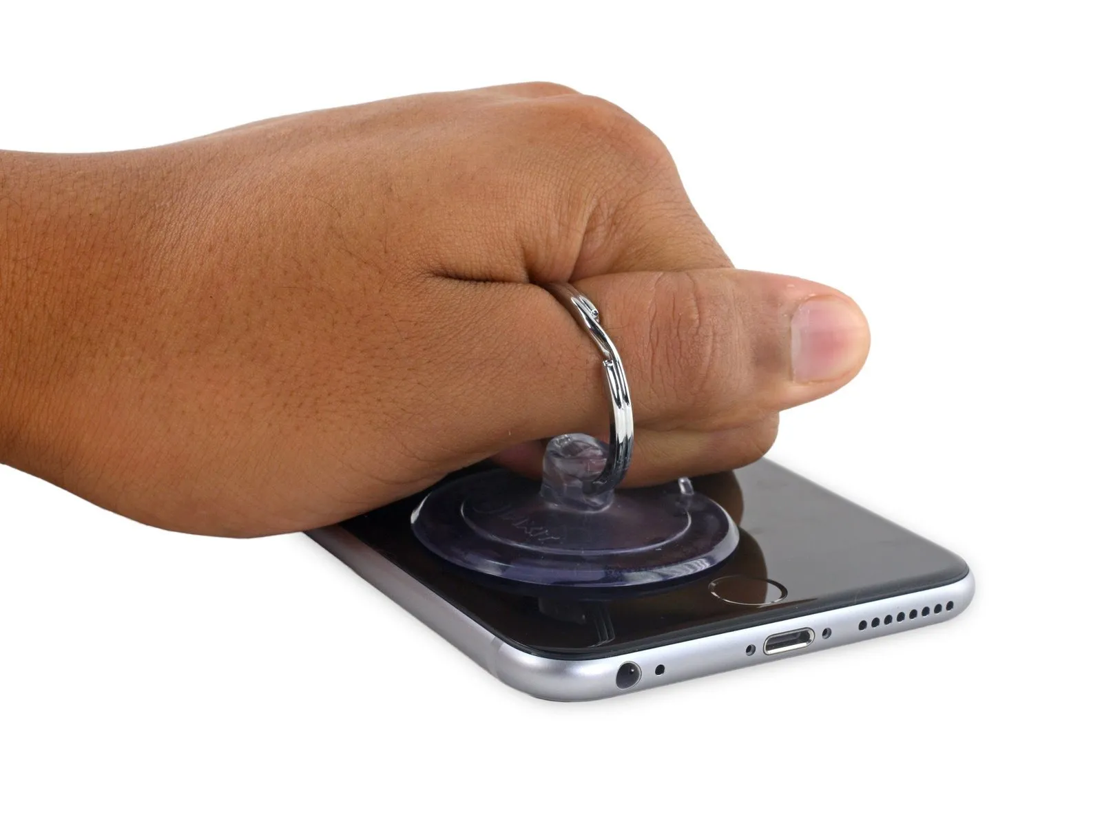
- To separate the front panel from the rear case, exert steady and forceful upward pressure on the suction cup, which should generate a minimal space.
- Excessive force during separation carries a risk of display assembly damage; therefore, only apply the necessary pressure to establish a small separation between the display assembly and the rear case.
Step 7

- Initiate the separation process by applying leverage from the indentation situated on the front panel, positioned directly over the headphone jack, as this area presents the lowest risk of damage.
- Continuing to apply consistent downward force with the suction cup, carefully slide the thin, wedge-shaped end of a spudger into the newly formed separation, precisely located above the headphone jack.
Step 8
- Utilize the spudger, rotating it to incrementally increase the separation between the front panel assembly and the rear casing.
Step 9


Step 10
Step 11


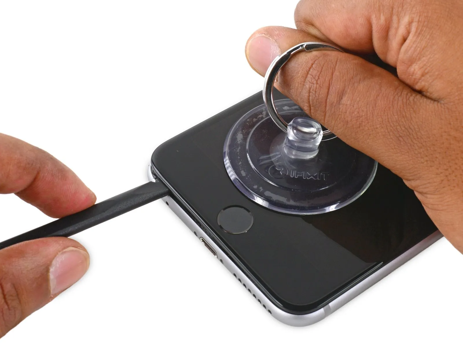
- Employ the planar end of the specified tool to gain access beneath the rightmost perimeter of the display assembly.spudgerCarefully maneuver the tool to create a separation gap along the right edge of the display.
- Utilize the spudgerto advance upwards along the right vertical plane.
Step 12


- Employ aplastic opening toolto maintain pressure on the back cover as you lift the suction cup, facilitating the phone's opening.
- Caution:Avoid detaching the display assembly entirely, as doing so risks harming the delicate data cables situated close to the upper portion of the iPhone.
Step 13

Step 14

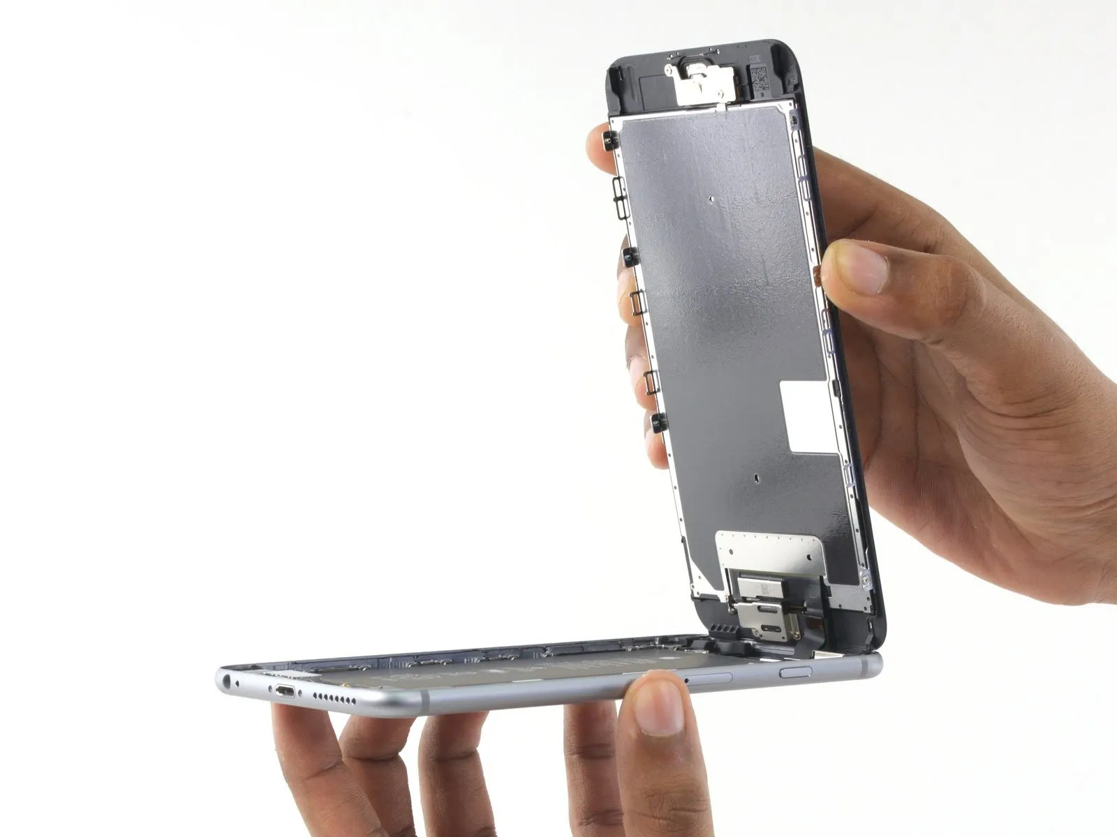

- Extend the display to a position of approximately 90 degrees,
- and secure it in a supported position to maintain access to the internal components during the repair.
Employ a rubber band to maintain the display's stability and secure positioning during the repair process, thereby minimizing stress on the connecting cables.
As an alternative solution when a rubber band is unavailable, an unopened beverage container can be used to provide support for the display.
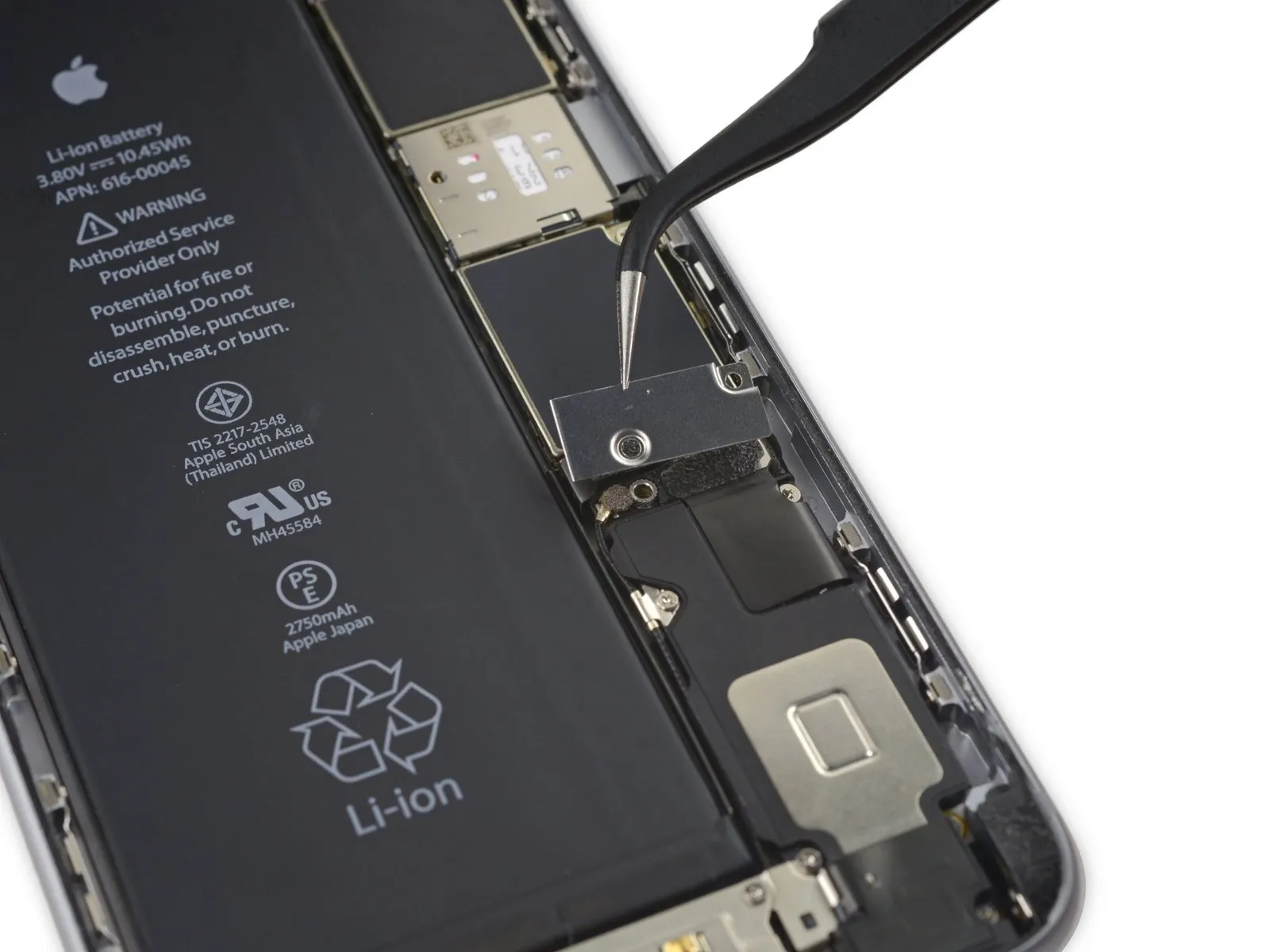
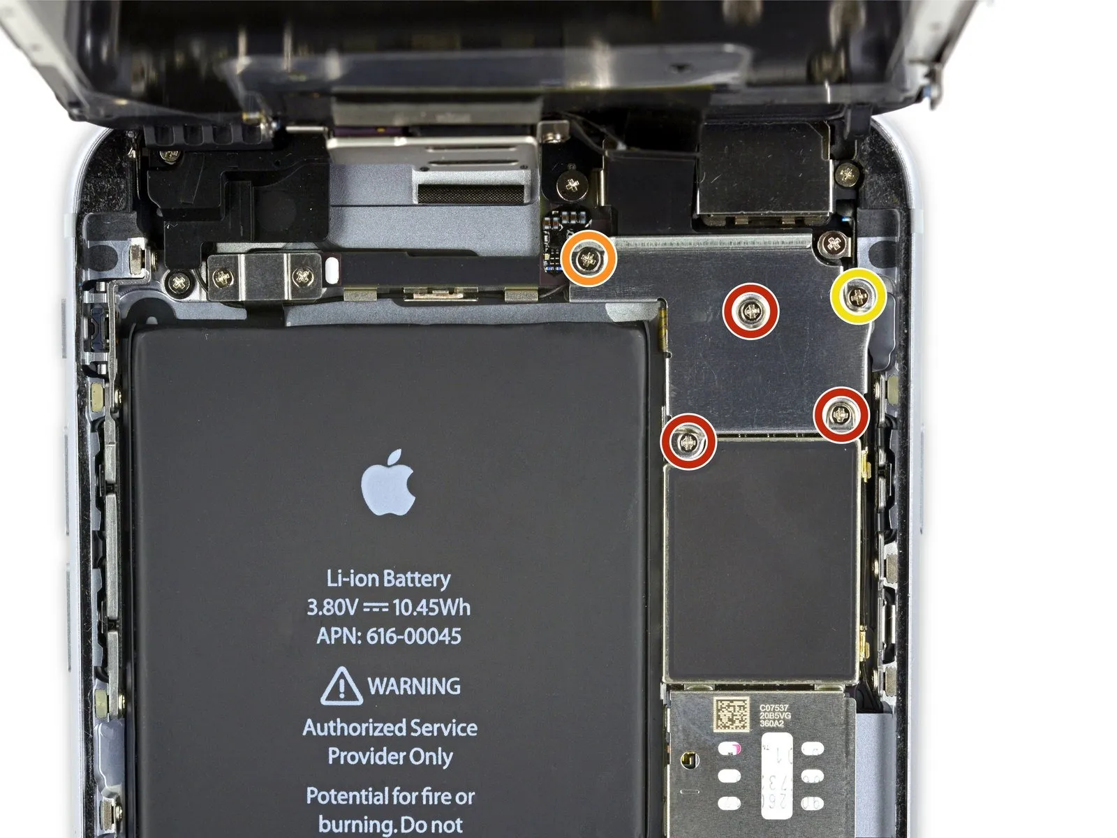
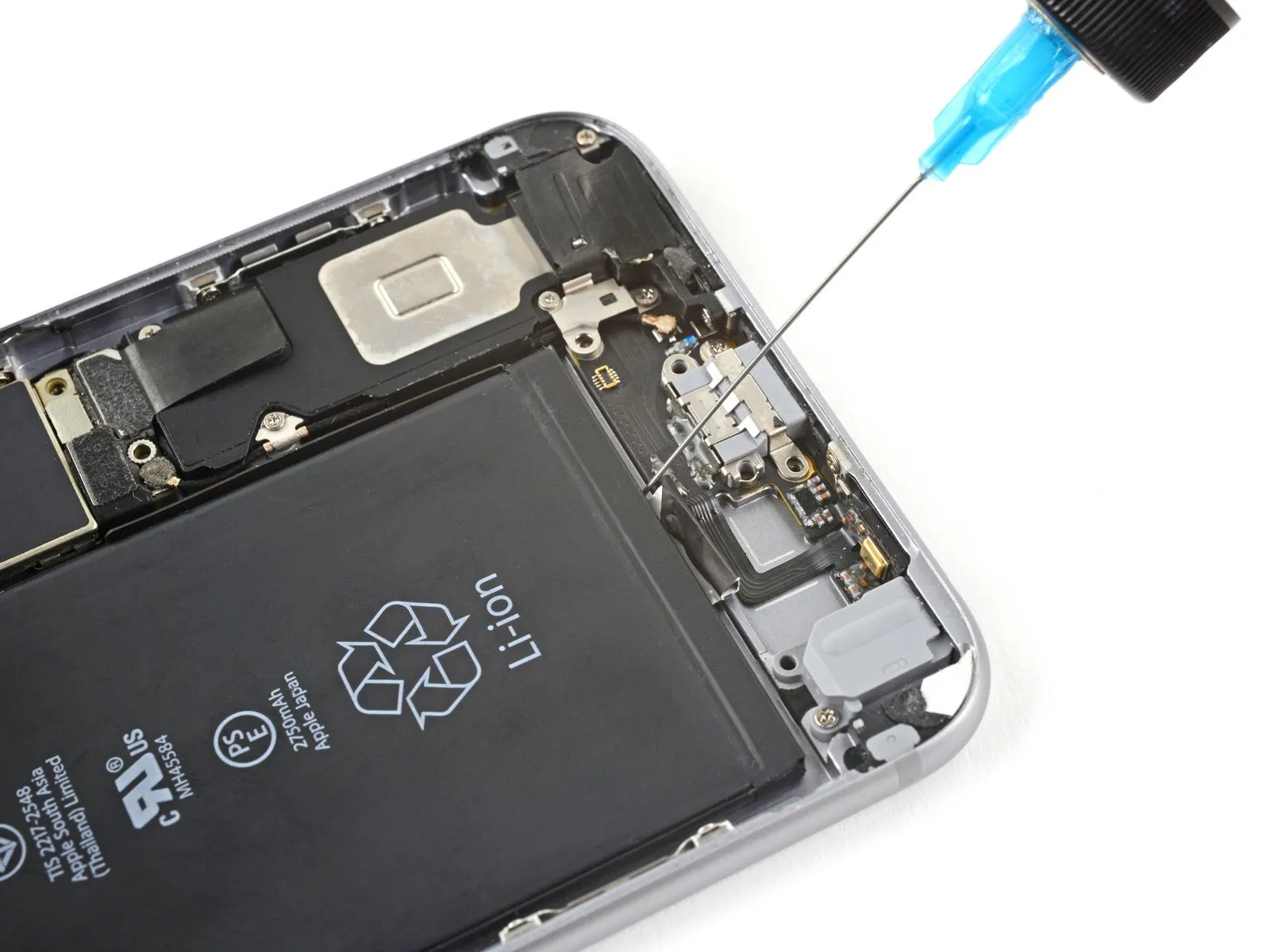
Step 15 | Battery Connector
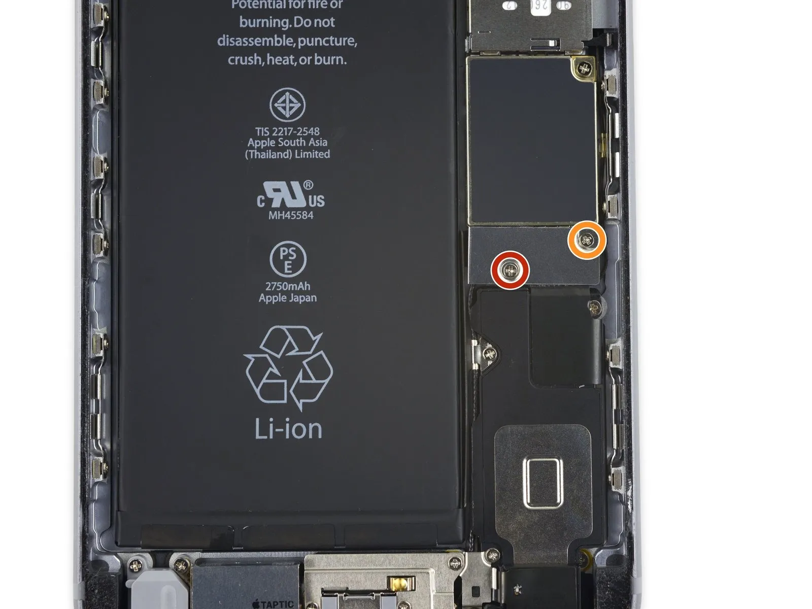
- - A single screw measuring2.9 mm in length,
- - Another screw with a length of2.3 mm. Observe that the screw lengths differ.
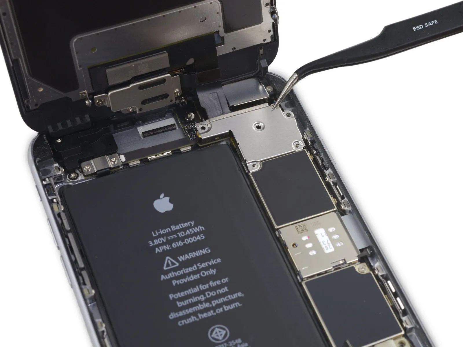
Step 16
Step 17
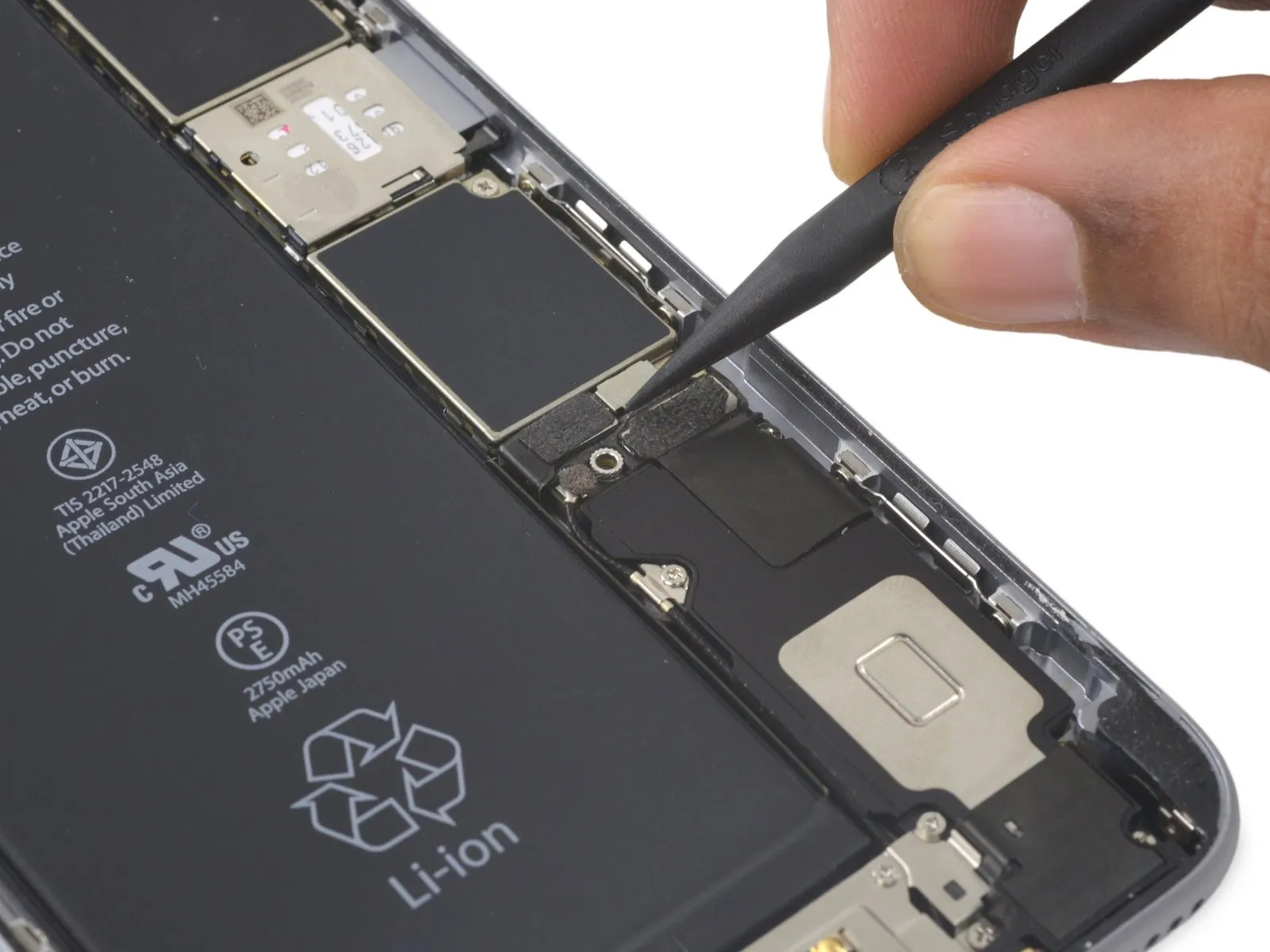

Employ a spudgeror a pristine fingernail to release the battery connector's grasp on the logic board, achieving separation through a direct upward motion.
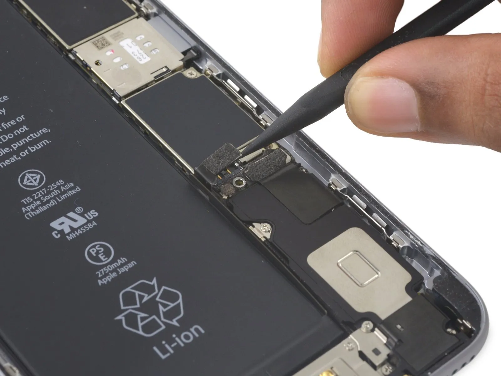
Step 18


To prevent unintended electrical connections, carefully restore the connector to its original shape, then activate the iPhone's power functions while continuing the repair process.
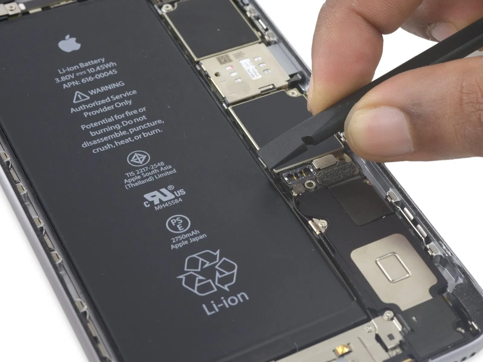
Step 19 | Display Assembly
- To proceed with the repair, detach the components listed below.Utilize Phillips head screwdrivers to remove these fasteners.:
- Specifically, three screws with a diameter of 1.3 millimeters are required for removal.
- Additionally, one screw measuring 1.6 millimeters in diameter must be extracted.
- A single screw with a 3.0-millimeter diameter is also part of the disassembly process.
When reassembling the device, ensuring the correct positioning of this3.0-millimeter screw within the top-right corner of the bracket is essential; incorrect placement could potentially harm the logic board.
Step 20

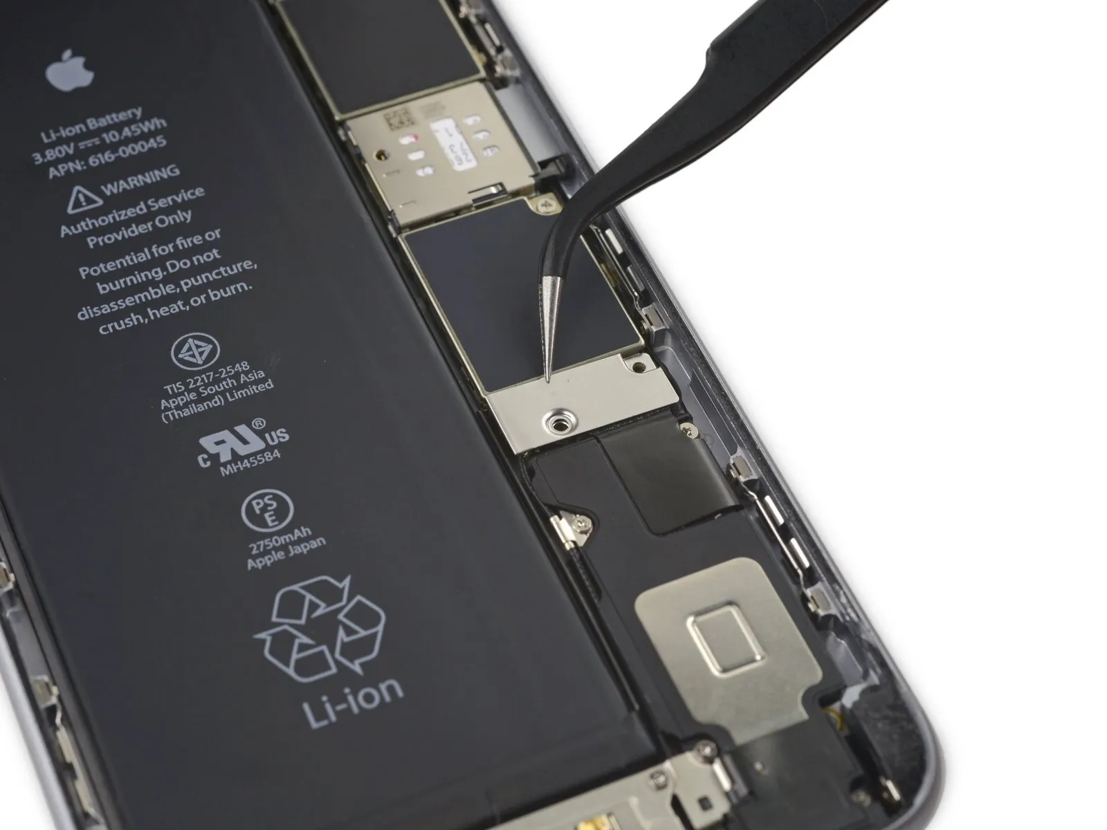
Detach the securing bracket that holds the display cable in place.
Step 21

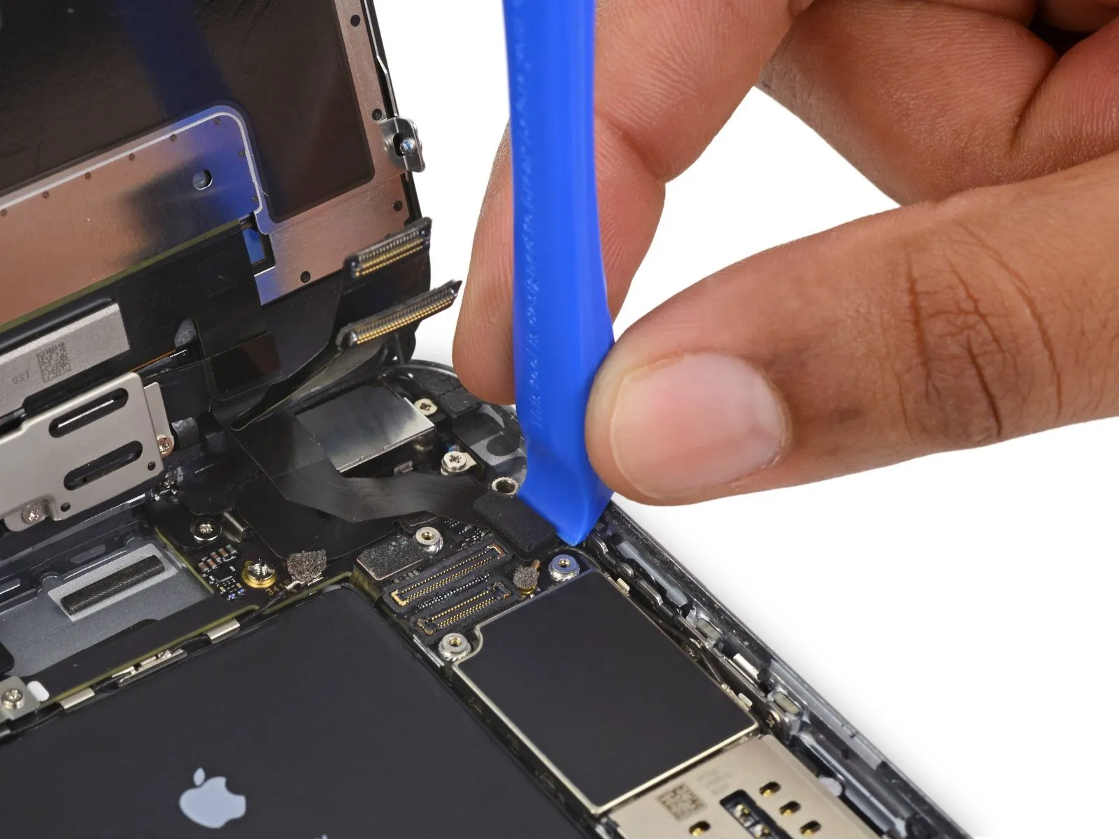
- Exercise caution, ensuring that force is applied solely to the connector body, avoiding damage to the socket situated on the logic board.
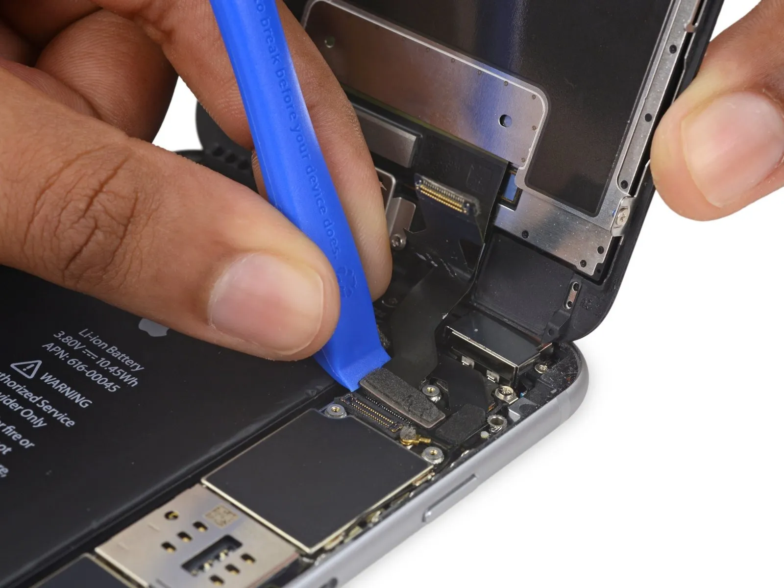
- Employ a plastic opening toolfor the purpose of detaching the front-facing camera and sensor cable connector.
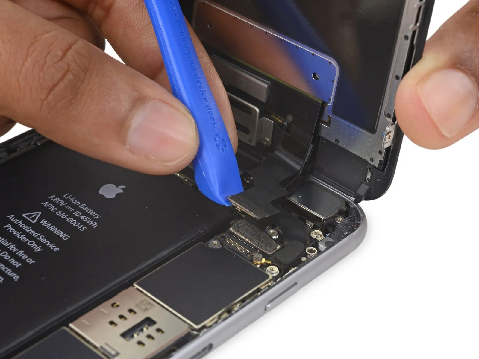
Step 22

- Employ a plastic opening tool to release the digitizer cable's connection, lifting it vertically from its position within the socket on the logic board.A plastic opening tool is required for this step.To ensure proper reattachment, avoid applying pressure to the central portion of the digitizer cable connector; instead, sequentially press one end, followed by the opposing end, to prevent deformation.
- Applying force to the connector's center risks bending the component.Such bending can lead to failure of the digitizer.This completes the digitizer cable procedure.
Step 23

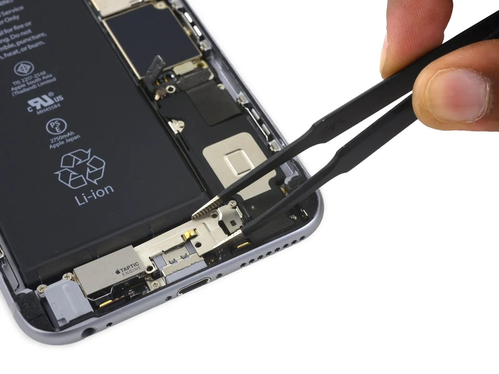
- Prior to detaching or reattaching the cable within this procedure, confirm the battery's power is completely inhibited.
- To release the home button/fingerprint sensor cable, apply upward force directly to it, separating it from its connection point on the logic board.
Step 24
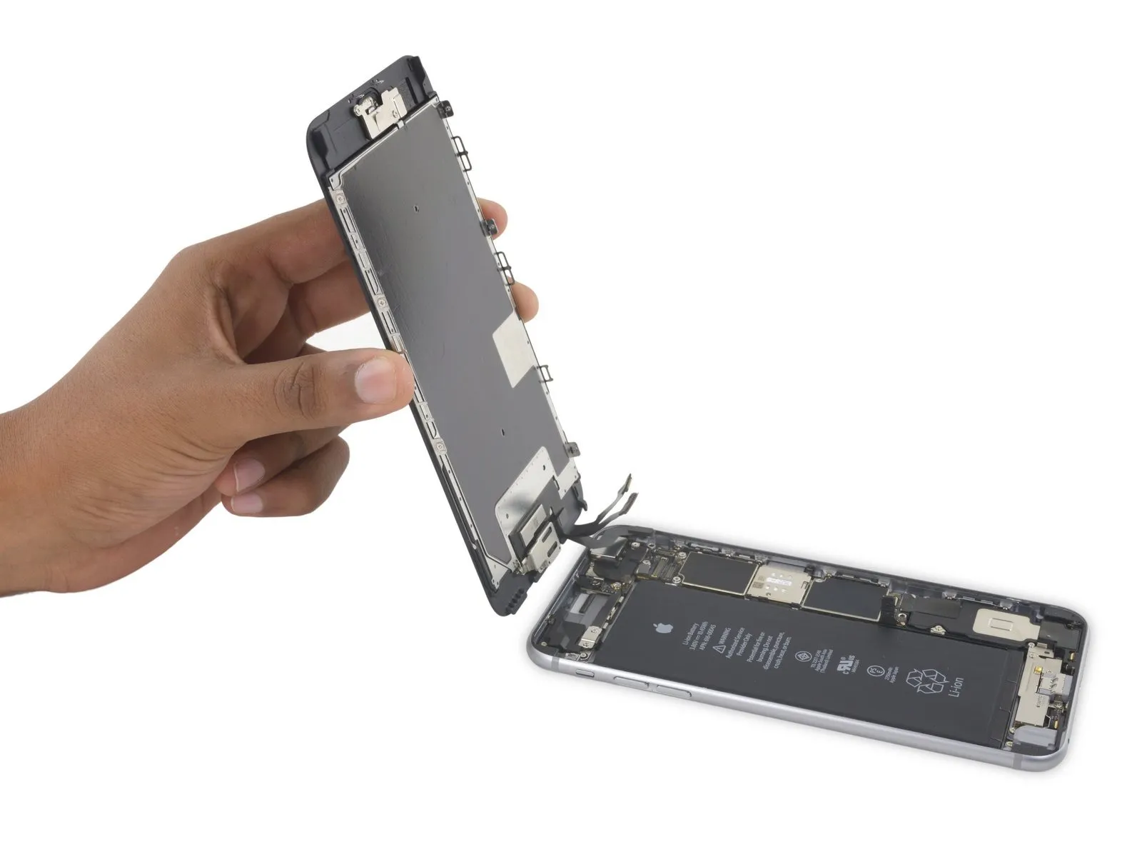
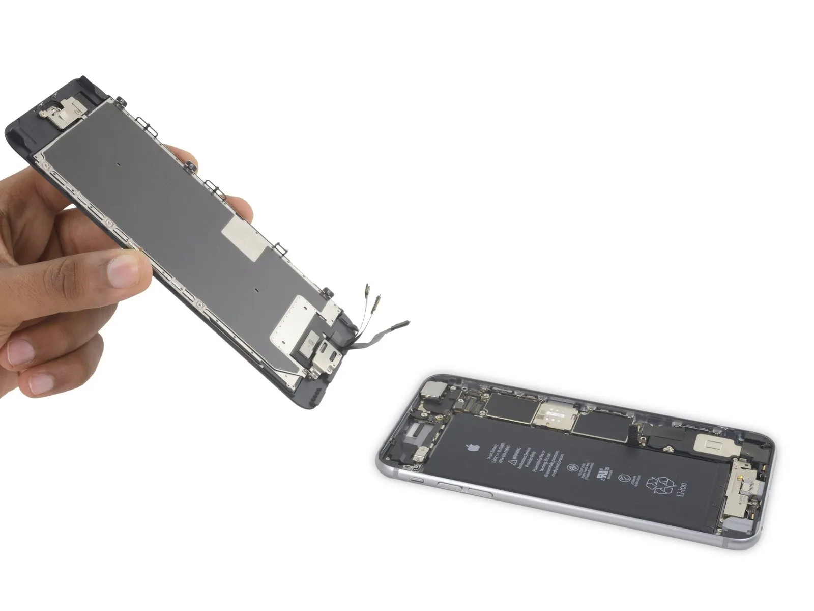
- Detach the display unit from the device.
- If you intend to substitute the adhesive securing the display's perimeter during reinstallation, halt the process at this juncture.
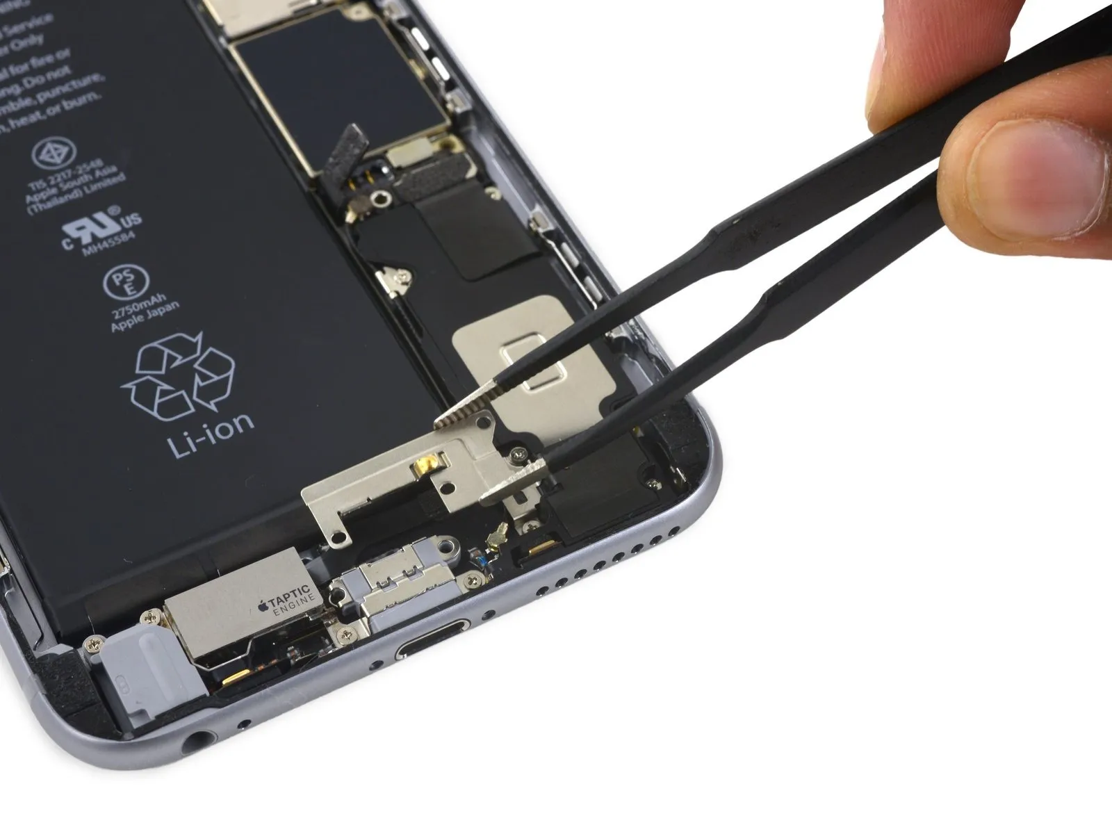
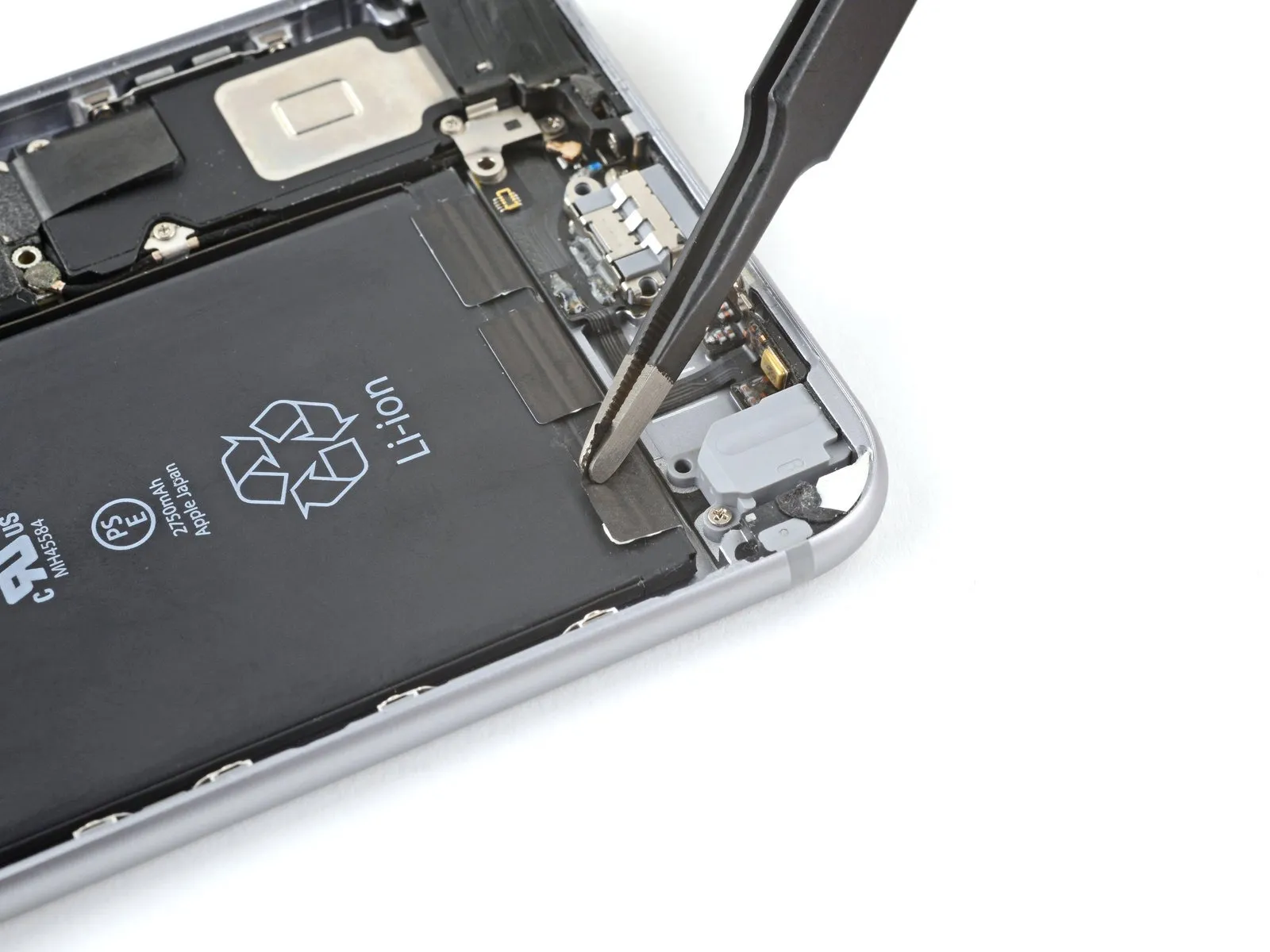
Step 25 | Taptic Engine

- Detachthe subsequentPhillips head fastenerssituated on the Taptic Engine cable bracket:
Employ two screws, each measuring 3.5 millimeters in length,
along with a single screw with a 2.7-millimeter dimension
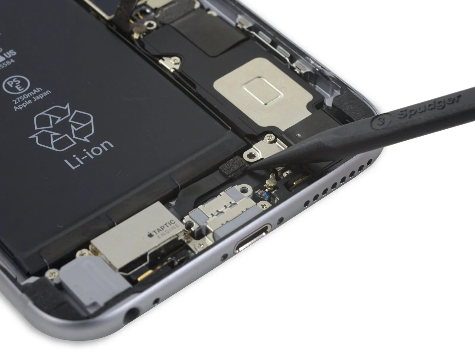
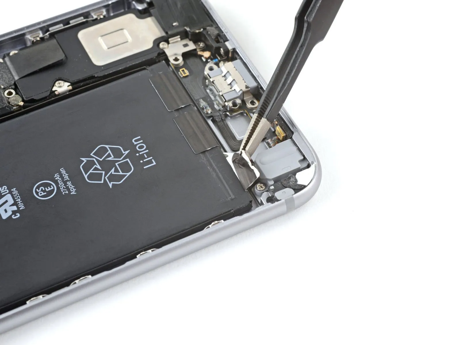
Step 26
- Detach the securing bracket that holds the Taptic Engine cable in place.Carefully disengage the bracket previously affixed to the Taptic Engine cable.
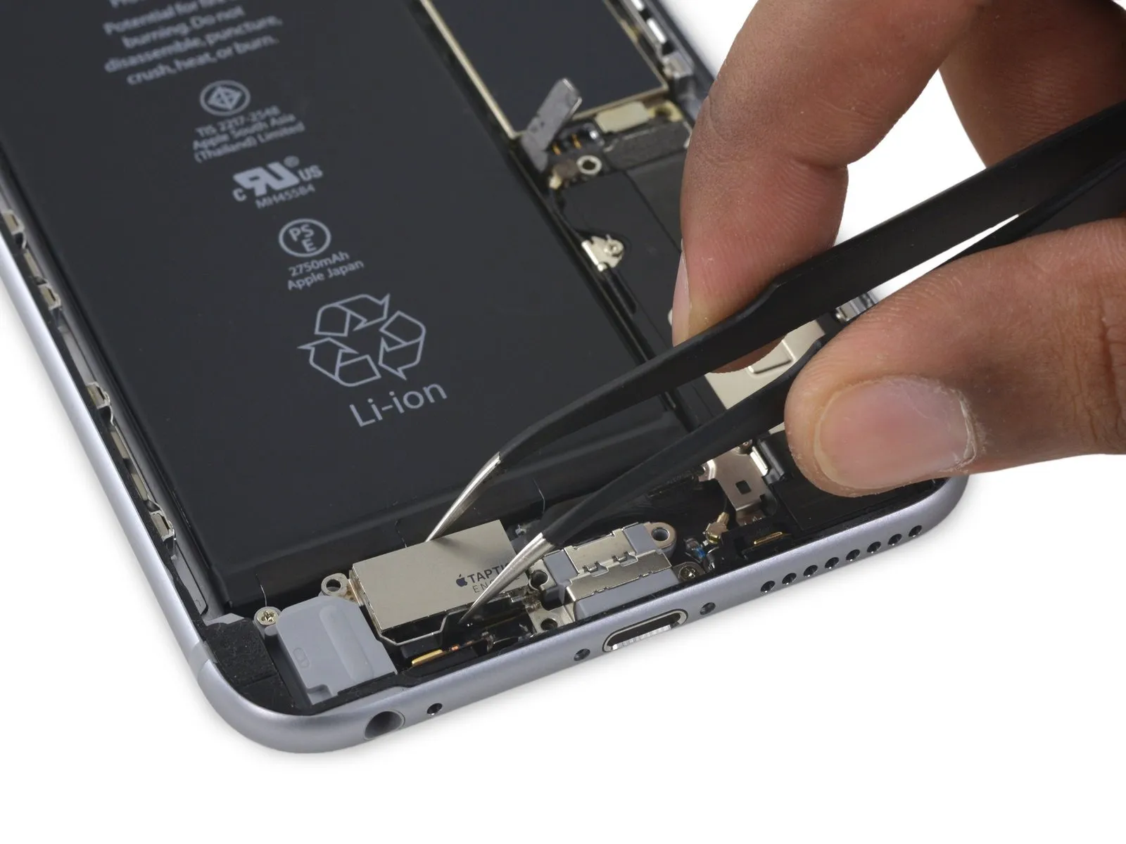
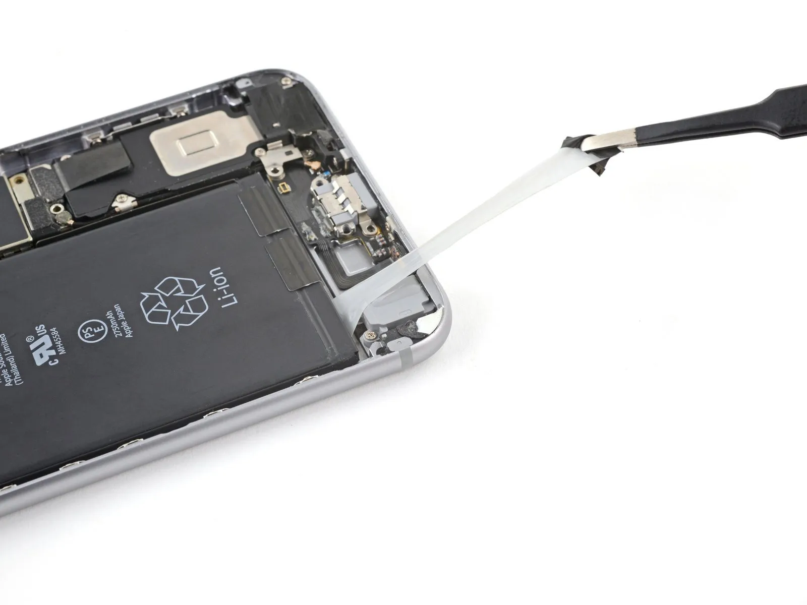
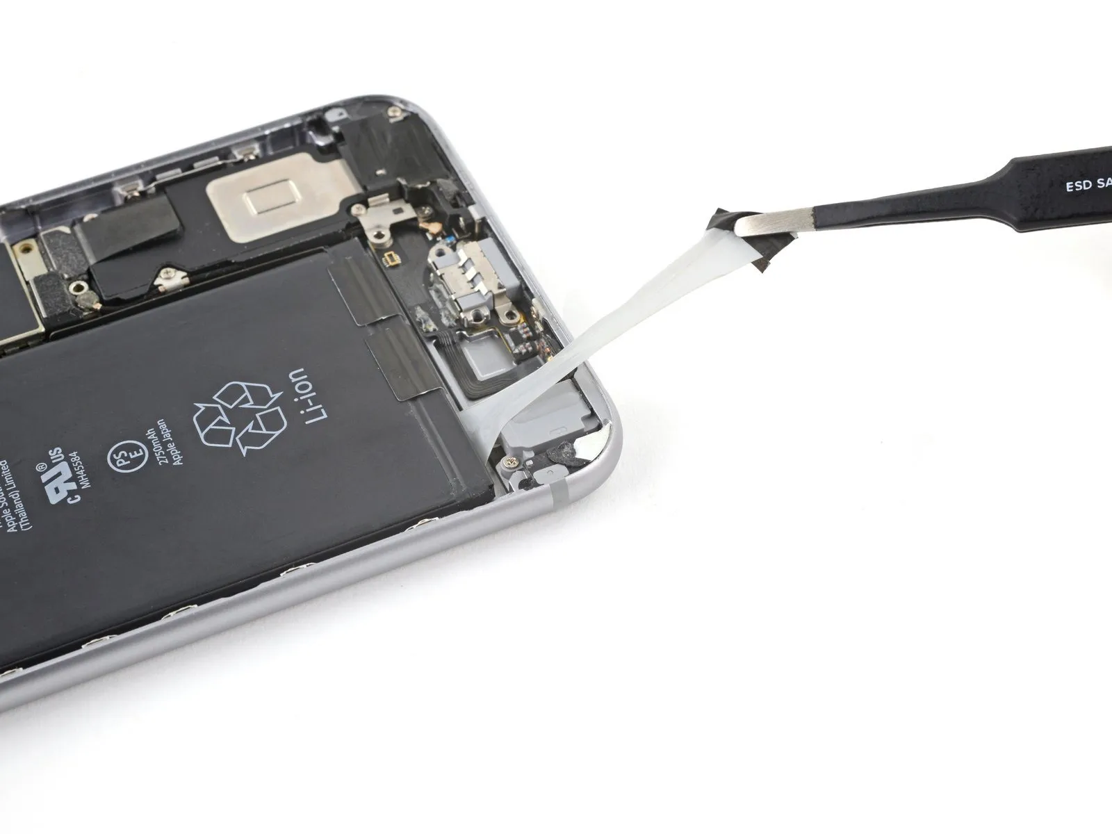
Step 27

- To proceed, detach the flex cable connecting the Taptic Engine from its corresponding connector situated on the Lightning Connector flex cable.Carefully separate the Taptic Engine's flex cable from the receptacle on the Lightning Connector flex cable.
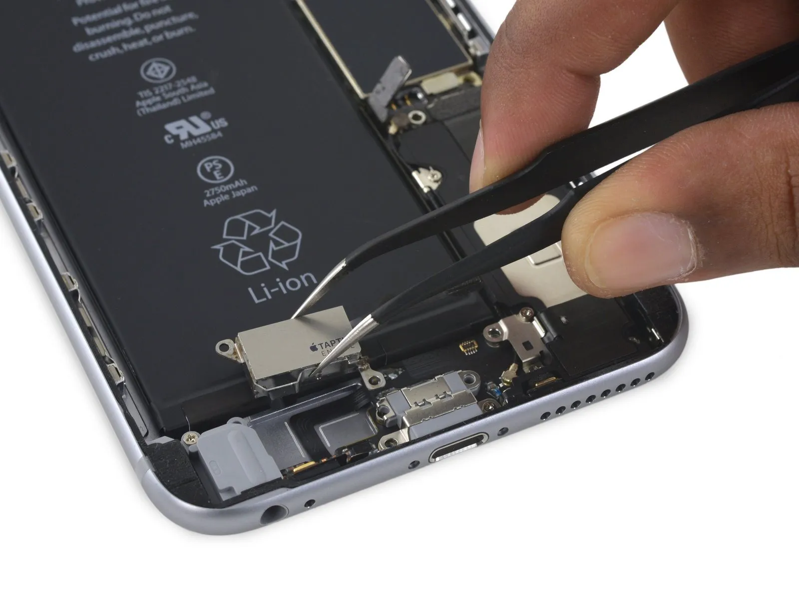
Step 28

- Detachthese subsequent fasteners,utilizing Phillips head screwdrivers,namely:
a single screw measuring 3.1 millimeters in length,
along with a single screw measuring 2.1 millimeters in length
Step 29
Step 30 | Remove the stretch-release adhesive
- Employ tweezers or your fingertips to carefully lift the black pull tab from one of the adhesive strips.
- Exercise caution to prevent puncturing or deforming the battery; damage to the battery can result in the release of hazardous chemicals or potentially trigger a fire.
Step 31

- Extract the adhesive strip gradually and uniformly, maintaining a shallow inclination, allowing ample time for it to extend and detach from beneath the battery.
- Should the adhesive strip fracture during removal, attempt to recover the fragments with your fingers or a non-pointed tool, and proceed with pulling, avoiding any leverage applied beneath the battery.
- For enhanced grip during extraction, you may choose to secure the pull-tabs around a spudger.
- Replicate this extraction method for each of the remaining stretch release adhesive strips.
- If the adhesive fragment becomes detached from beneath the battery and is irretrievable, proceed directly to the subsequent step.
Step 32 | How to remove a stuck battery

- Should battery removal persist as a challenge, introduce a small quantity of high-purity (90% or greater concentration) isopropyl alcohol beneath the battery's edge, specifically targeting the damaged adhesive strip(s).
- Position the device with an upward angle, facilitating the movement of isopropyl alcohol towards the adhesive bond.
- Maintain this position for a duration of 1 to 2 minutes, enabling the isopropyl alcohol to degrade the adhesive's strength.
- Employ an opening pick or the planar end of a spudger to gently lift the battery from its position.
Step 33
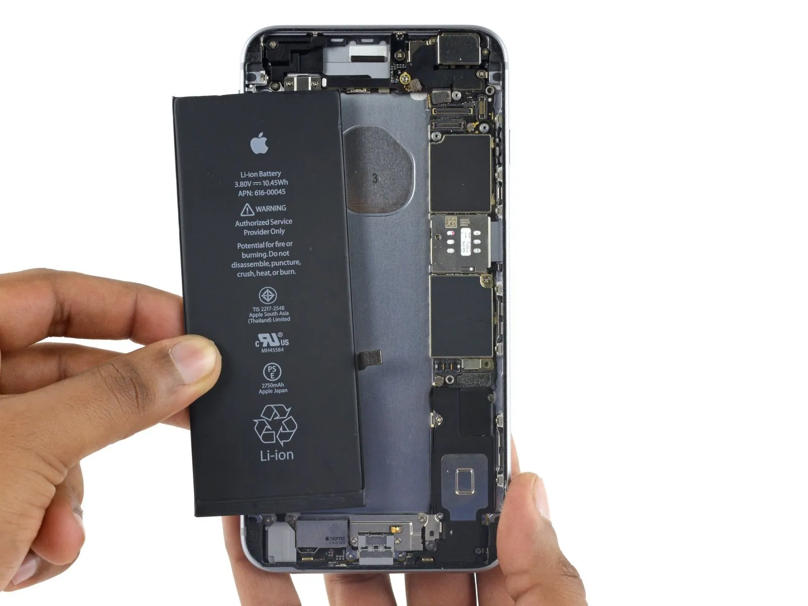
- Detach the battery from its location.
- Should your newly acquired battery be encased in a plastic covering, extract it by separating it from the ribbon cable before proceeding with installation.
- Ensure complete evaporation of any residual alcohol within the device's interior, either through careful wiping or allowing it to dry naturally.
- Prior to securing the replacement battery in place, briefly reconnect the battery connector to its corresponding socket on the logic board; this action facilitates correct positioning within the designated recess.
- Secure the battery with adhesive, subsequently disconnect it, and proceed with the remaining reassembly steps.
- In the event that your replacement battery lacks pre-applied adhesive, consult this guide for instructions on replacing the adhesive strips.
- Following the completion of reassembly, execute a hard reset to mitigate potential problems and streamline any necessary troubleshooting.