iPhone 6s Plus Home Button Assembly Replacement
Adhere to the procedures detailed within this manual to substitute theHome Button Assembly, encompassing both the gasket and connecting cable, within your iPhone 6s Plus. Be aware that the functionality of Touch ID will be lost following the replacement of the Home Button Assembly, as these components are intrinsically linked to their corresponding logic board.
- This guide is also applicable for the procedure of replacing thehome button bracket.
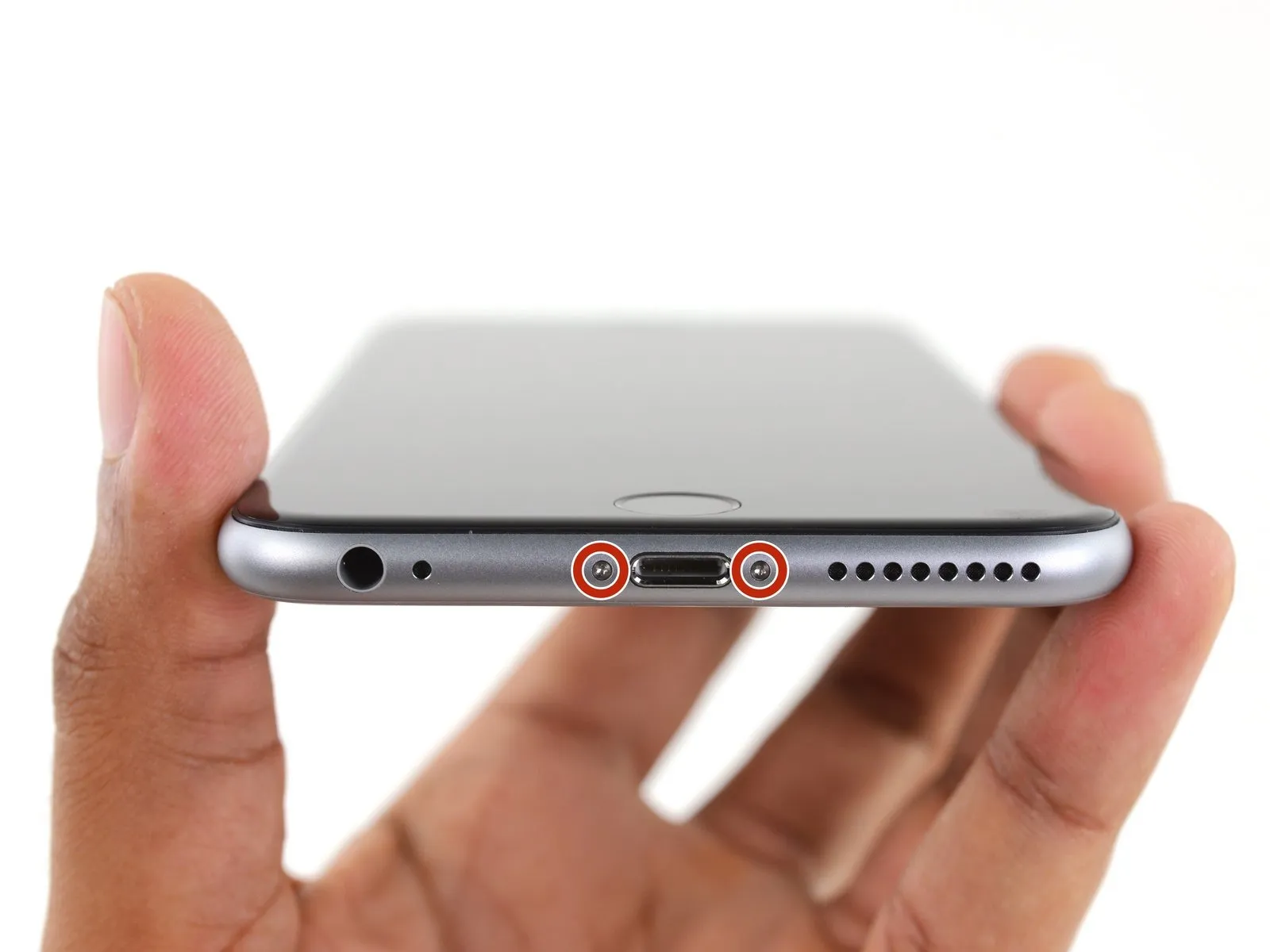
Step 1 | Pentalobe Screws
- Ensure the lithium-ion battery's charge level is less than 25%; a fully charged battery presents a fire hazard and potential explosion risk if damaged.
- Deactivate the iPhone's power supply to prevent any electrical issues during the disassembly process.
- Begin the disassembly by eliminating the pair of 3.4 mm Pentalobe screws located on both sides of the Lightning connector.
Step 2 | Anti-Clamp instructions


- Should you choose not to utilize the Anti-Clamp, proceed to the instructions located three steps further down for an alternative approach.
- Detailed guidance regarding the Anti-Clamp's operation can be found within this separate instructional document.
- To release the Anti-Clamp's gripping arms, retract the blue handle towards the rear.
- Carefully position the arms across either the left or right side of your iPhone's frame.
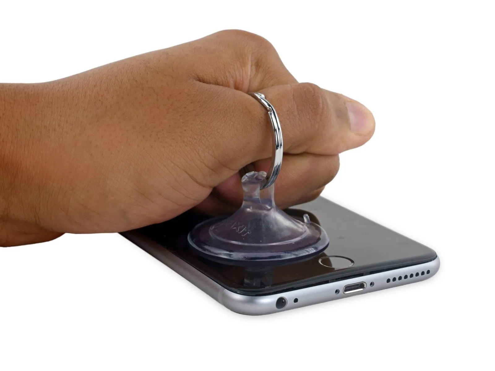
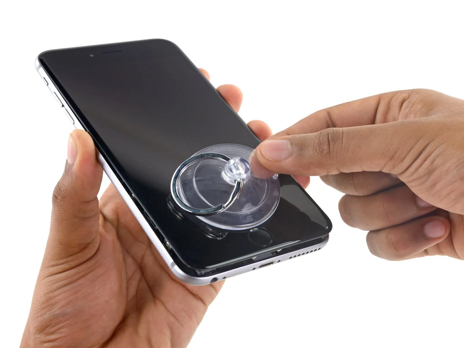
- Place the suction cups close to the lower edge of the iPhone, situated directly above the home button; one cup should be on the front surface, and one on the rear.
- Apply pressure by compressing the cups together to establish a secure suction hold on the intended area.
- In cases where the iPhone's surface exhibits excessive slipperiness, hindering the Anti-Clamp's ability to maintain grip, applying adhesive tape can provide a more textured surface for improved adhesion.
Step 3


- Rotate the handle a full 360 degrees, or continue turning until the suction cups begin to deform.
- Maintain proper alignment between the suction cups; should they become misaligned, slightly release the suction cups and readjust the arms.
Step 4 | Opening Procedure
- Introduce gentle warmth to the iPhone's lower border, employing either an iOpener or a hair dryer, for approximately one minute.
- The application of heat serves to reduce the stiffness of the adhesive that holds the display in place, thereby simplifying the opening process.
Step 5
- Should you wish to substitute the existing adhesive, ensure a fresh supply of adhesive strips is accessible prior to proceeding. The repair can be successfully finished without adhesive replacement, and operational performance is unlikely to be affected.
For displays exhibiting severe cracking, applying a transparent layer of packing tape can improve the suction cup's grip. Alternatively, a robust adhesive tape can be employed in place of the suction cup; if these methods prove ineffective, a small amount of superglue can be used to attach the suction cup to the fractured screen.
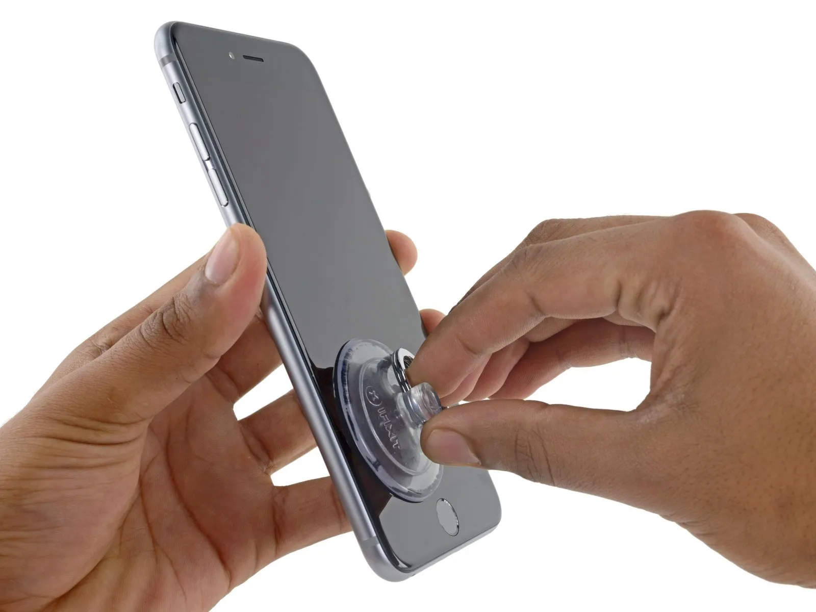
Step 6
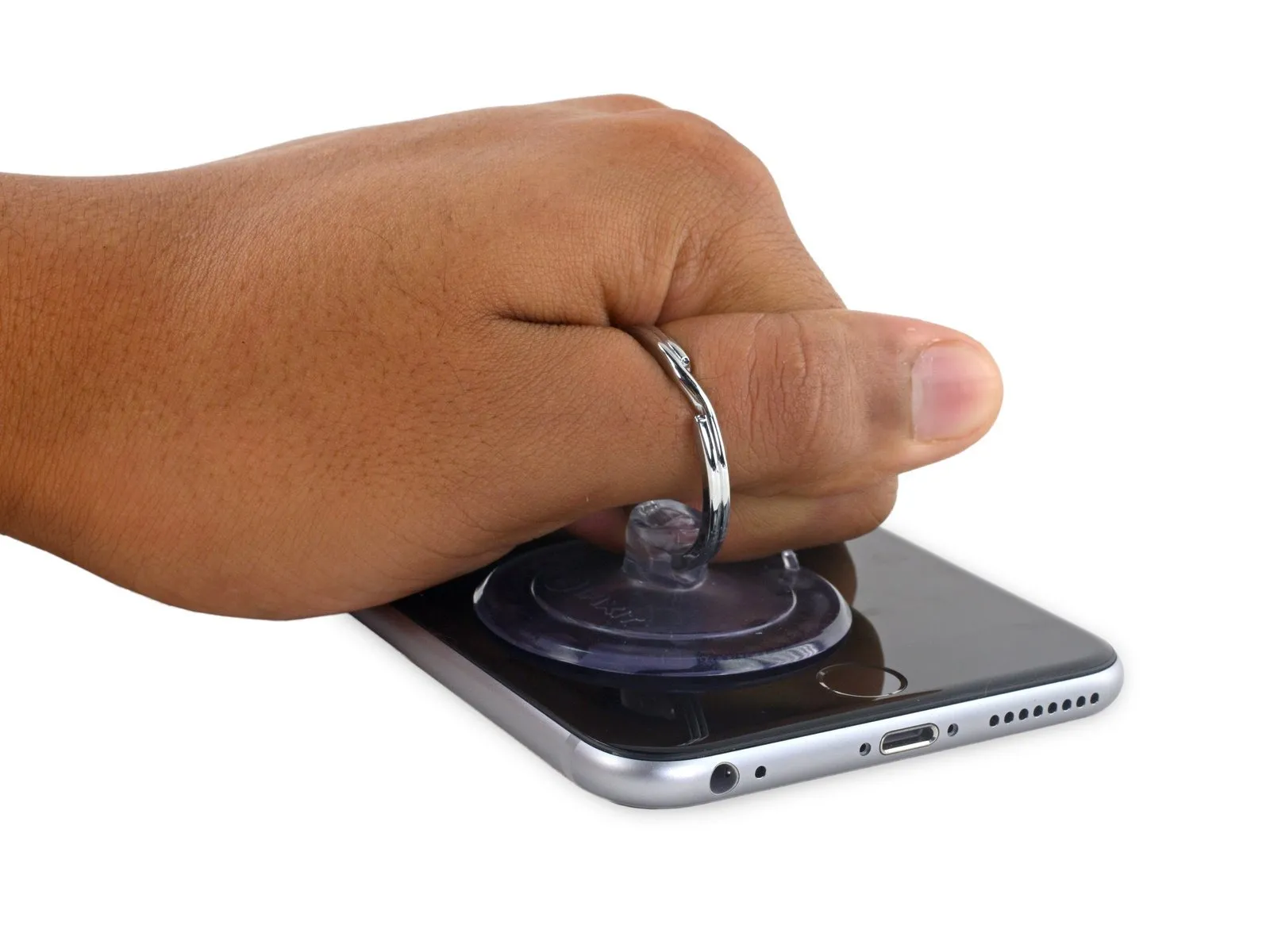
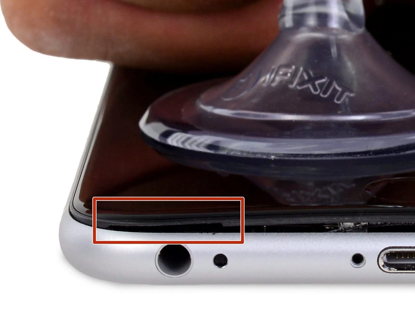
- To separate the front panel from the rear case, exert steady and consistent upward force on the suction cup, which should produce a minimal space.
Step 7

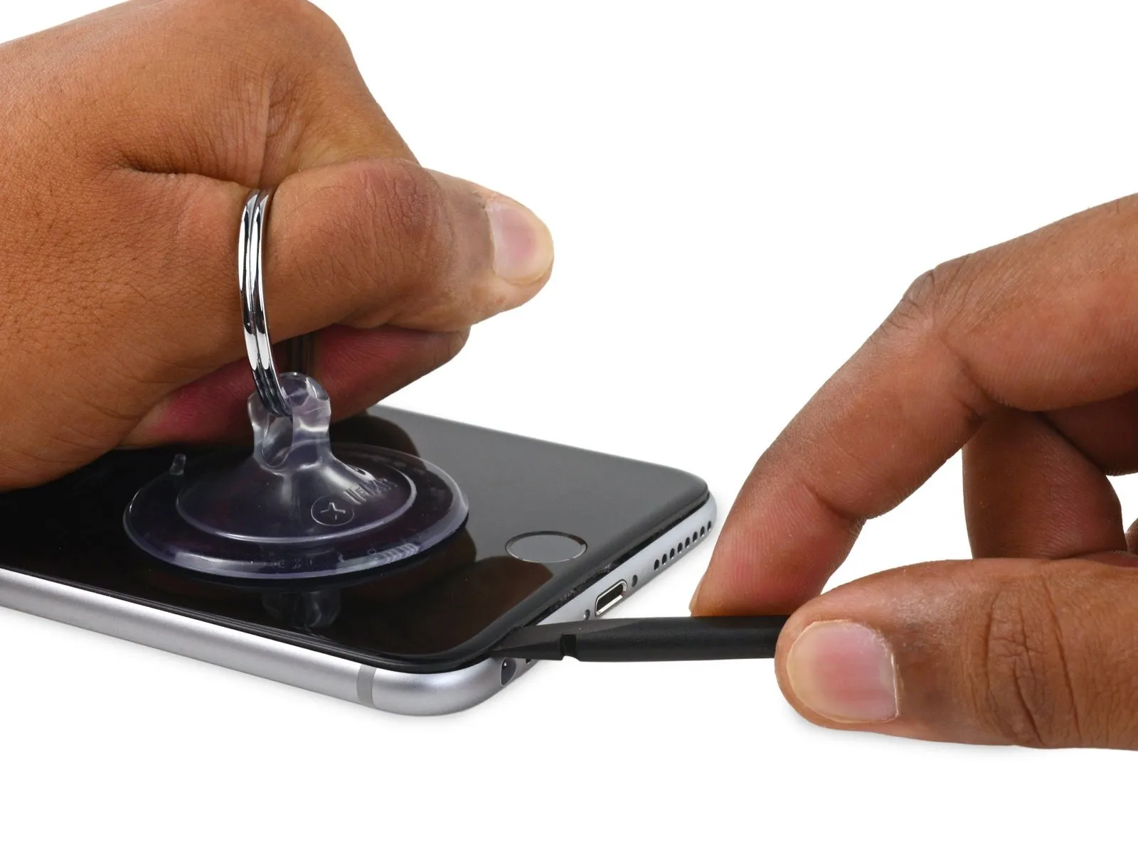
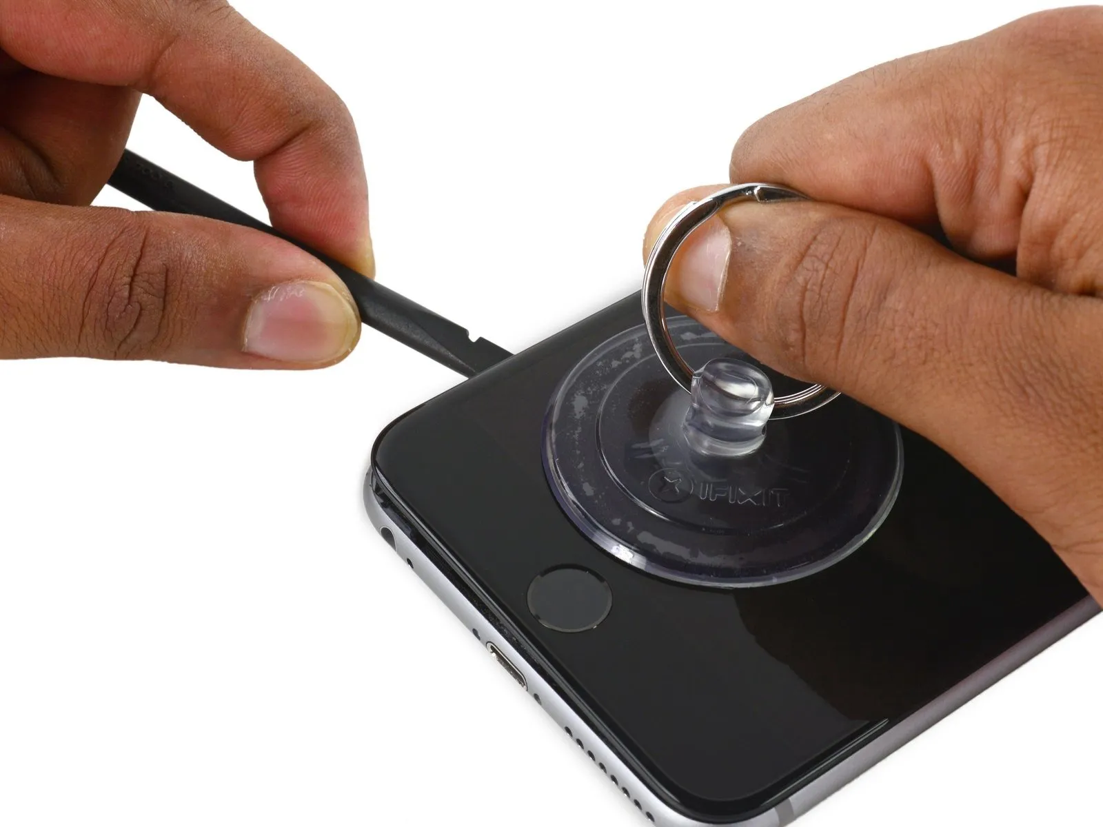
Continuing to apply consistent downward force with the suction cup, carefully slide the thin, wedge-shaped end of a spudger into the newly formed space, precisely located above the headphone jack.
Step 8
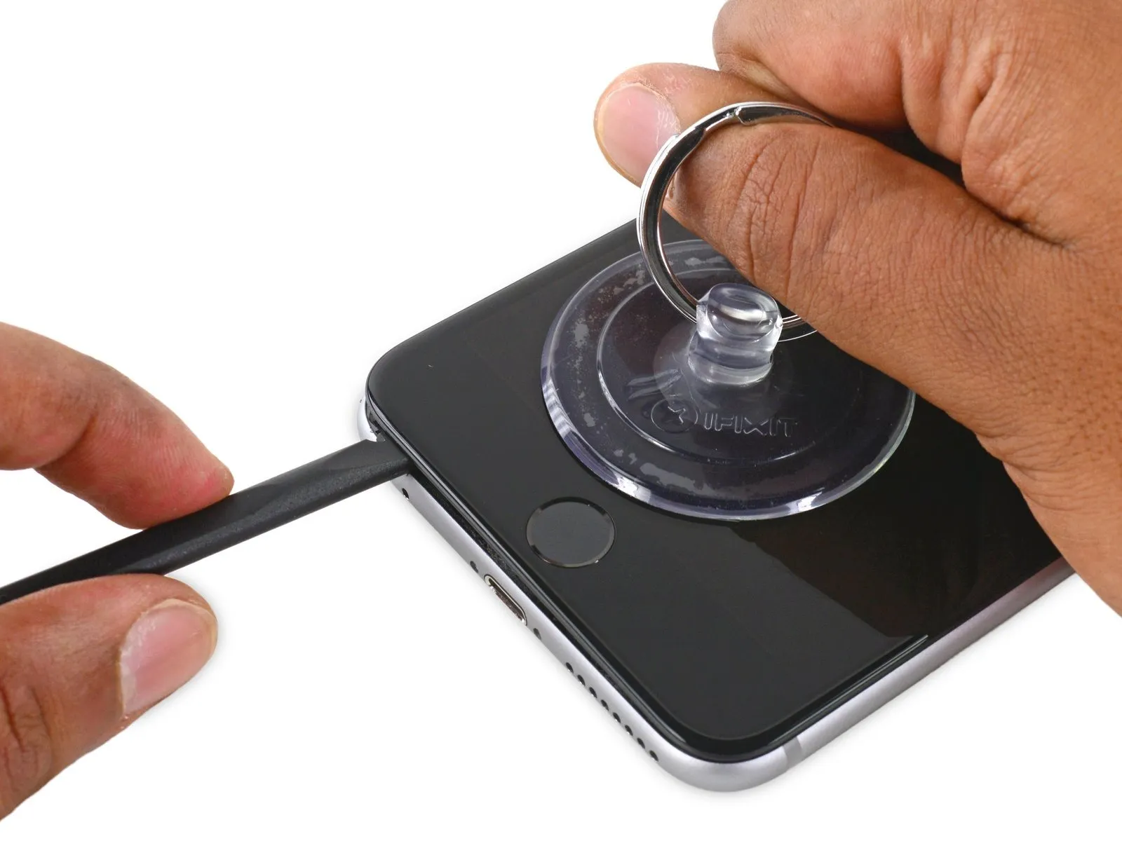
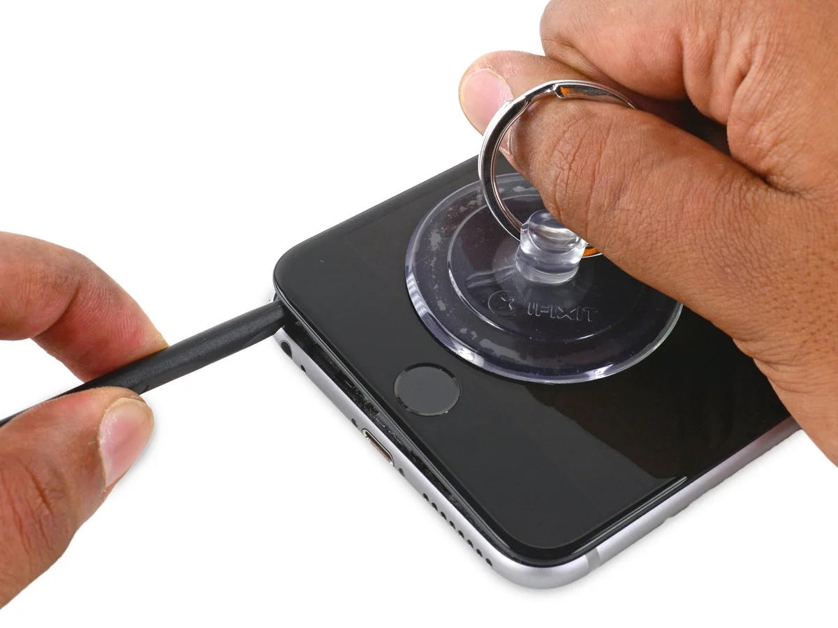
- Employ the spudger, rotating it to incrementally increase the separation between the front panel assembly and the rear case enclosure.
Step 9


Step 10
Step 11


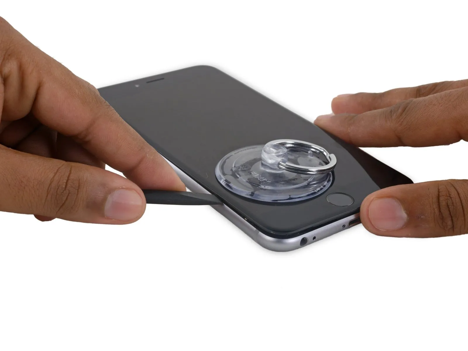
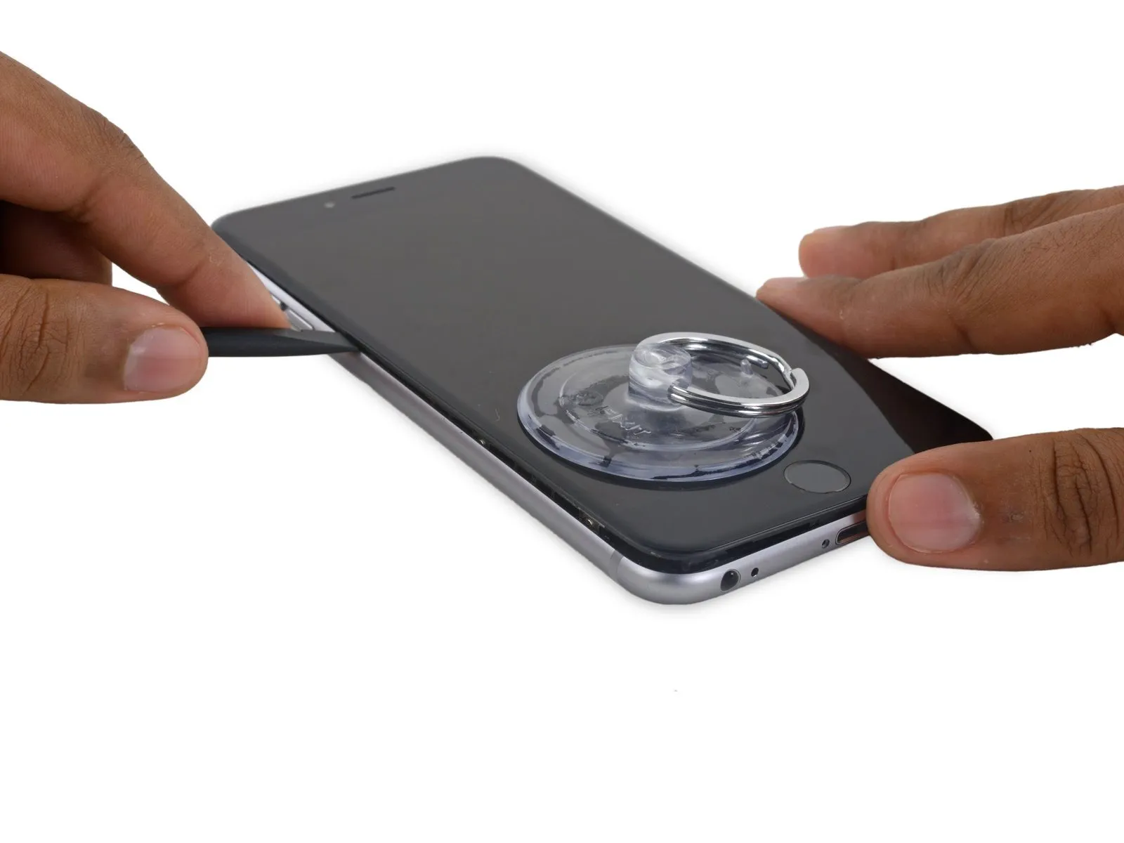
- Position the slender, flat end of the spudgerspudgerbeneath the rightmost border of the display assembly.
- Carefully move thespudgeralong the right vertical edge.
Step 12


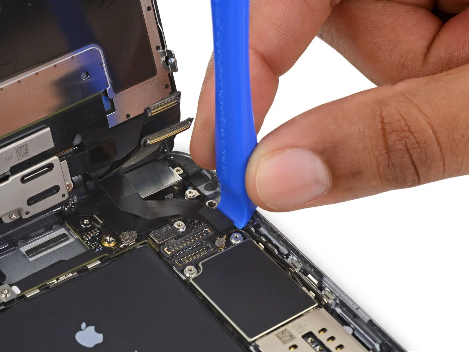
- Employ aplastic opening toolto maintain pressure on the back cover as you lift the suction cup, facilitating the phone's opening.
- Refrain from detaching the display assembly entirely,as doing so risks harming the delicate data cables situated close to the upper portion of the iPhone.
Step 13

Step 14

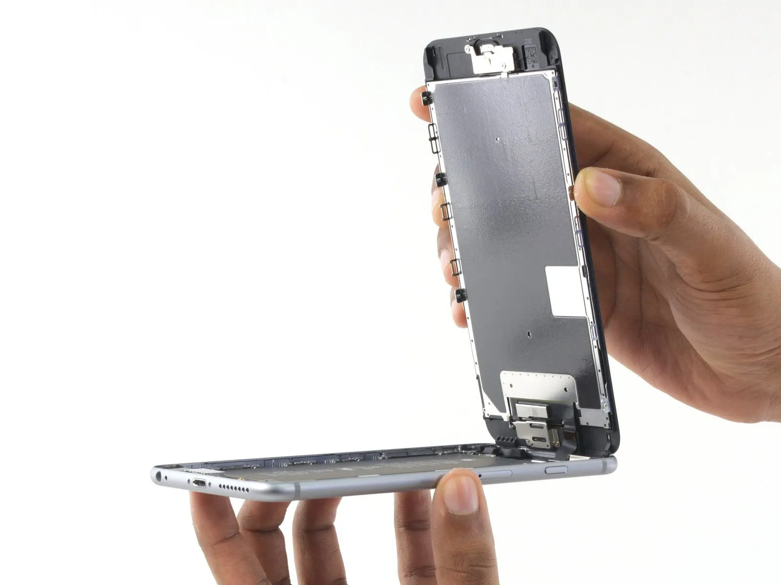

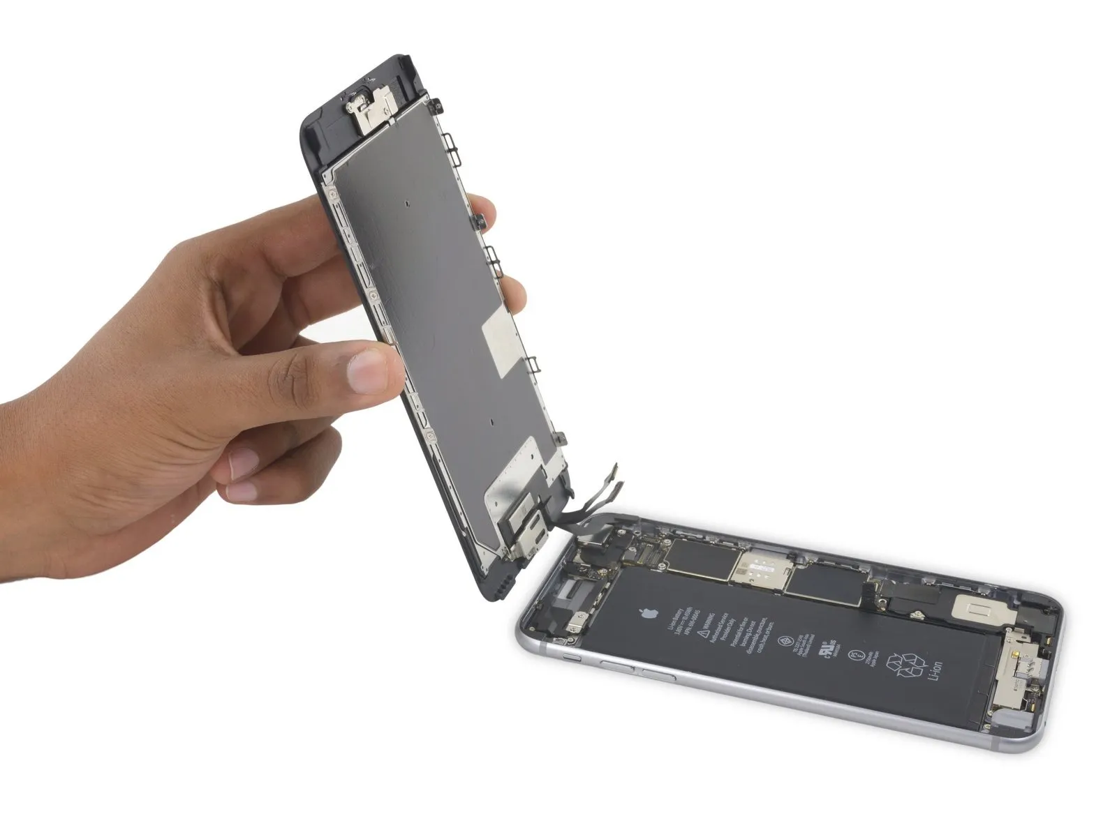
- Carefully take hold of the display assembly and raise it to initiate the phone's opening process, utilizing the clips located at the front panel's upper edge as a pivot point.
- Position the opened display at approximately a 90-degree angle and secure it against a stable surface to maintain its position during the repair process.
- Avoid exceeding a 90-degree opening angle, as the display remains connected to the phone's upper section via the display cable, digitizer cable, and front camera cable, which are susceptible to damage.
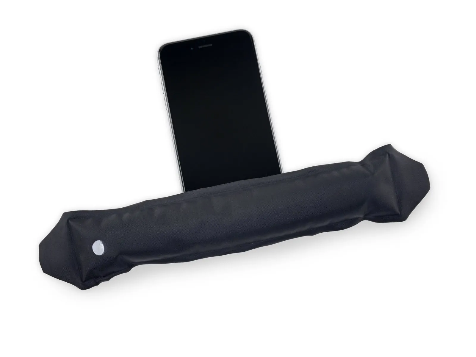
- Employ a rubber band to firmly secure the display in place, minimizing stress on the delicate display cables during the repair.
- As a temporary solution, an unopened, sealed beverage container can be used to provide support for the display.
Step 15 | Battery Connector
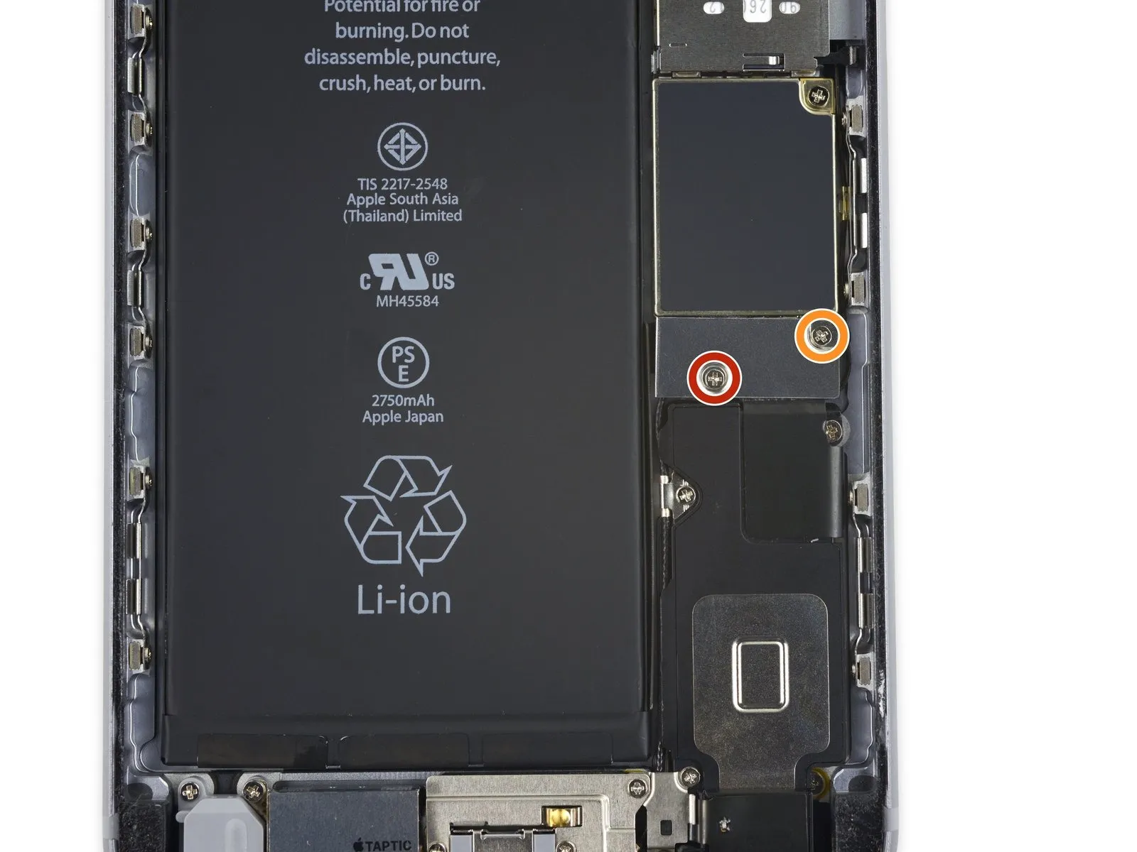
- To detach the battery connector bracket from the logic board, first, eliminate two Phillips screws that hold it in place; these screws have differing lengths.
A 2.9 mm Phillips screw is required for this step.
Additionally, a 2.3 mm Phillips screw is also needed.
During this repair process, meticulously organize all screws, ensuring each is returned to its original location during reassembly; incorrect screw placement can result in irreversible harm to the device.
Step 16
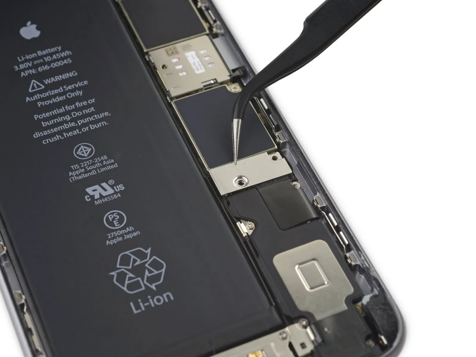
Step 17

Employ a spudgerAlternatively, a clean fingernail can be utilized to release the battery connector, achieved by applying upward pressure directly above the logic board.
Step 18


To prevent unintended electrical connections, carefully restore the connector to its original shape, then activate the iPhone's power functions while performing subsequent repair steps.
Step 19 | Display Assembly
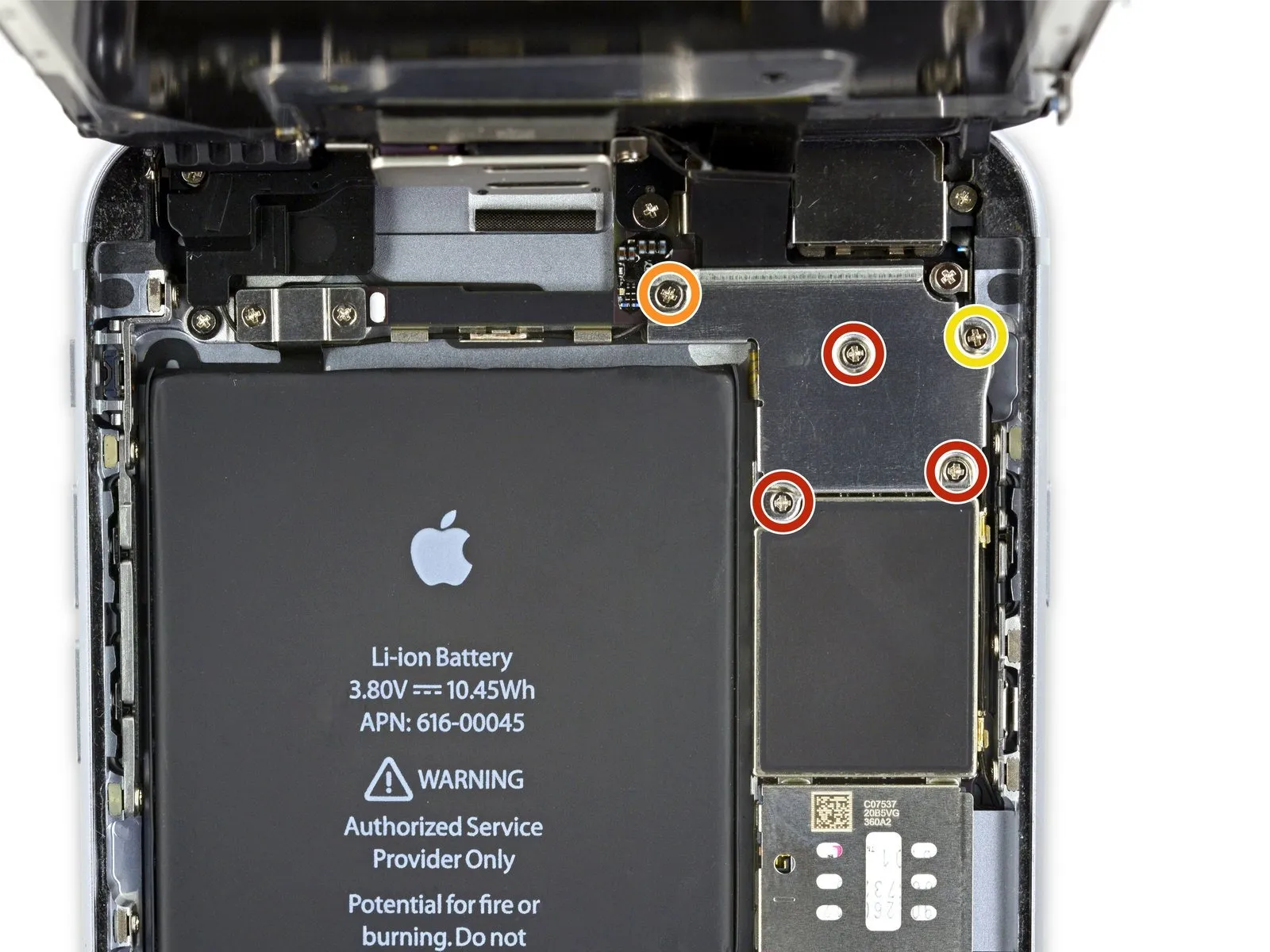
- To proceed with the repair, detach the subsequent components:Utilize Phillips head screwdrivers to remove these fasteners.:
- Specifically, three screws with a diameter of 1.3 millimeters are required for removal.
- Additionally, a single screw measuring 1.6 millimeters in diameter must be detached.
- A solitary screw with a 3.0-millimeter diameter also needs to be removed.
When reassembling the device, ensuring the correct positioning of this3.0-millimeter screw within the upper-rightmost section of the bracket is vitally important; incorrect placement could potentially harm the logic board.
Step 20
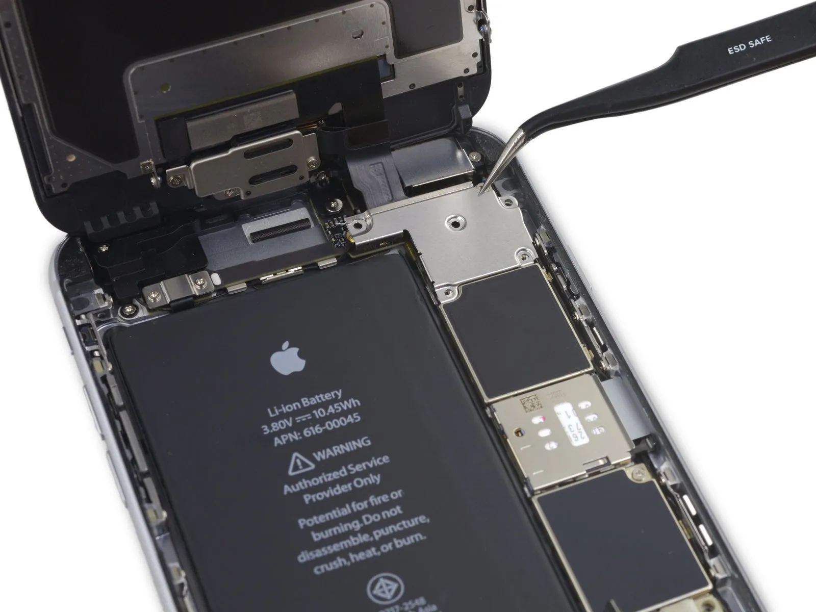

Detach the securing bracket that holds the display cable in place.
Step 21

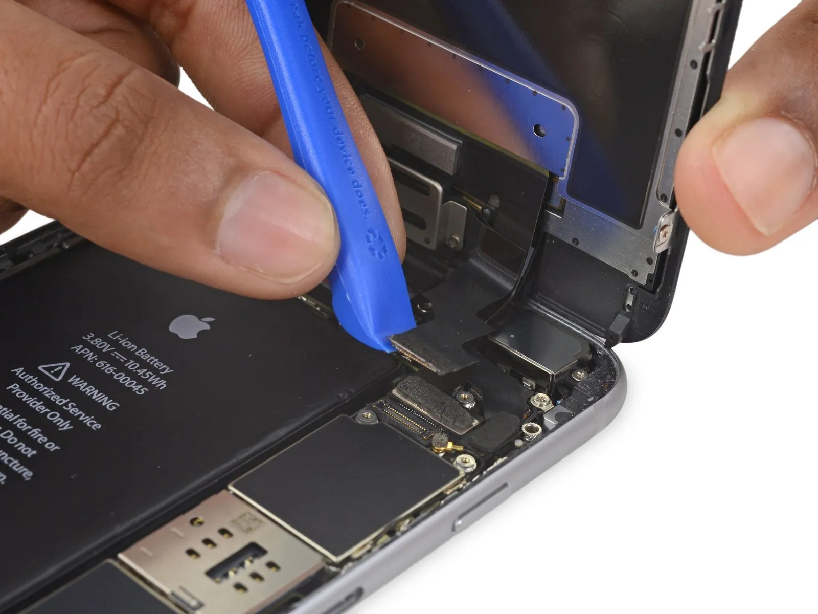
- Exercise caution, ensuring that prying force is applied solely to the connector body, avoiding damage to the socket situated on the logic board.
- Employ a plastic opening toolfor the purpose of detaching the front-facing camera and sensor cable connector.
Step 22
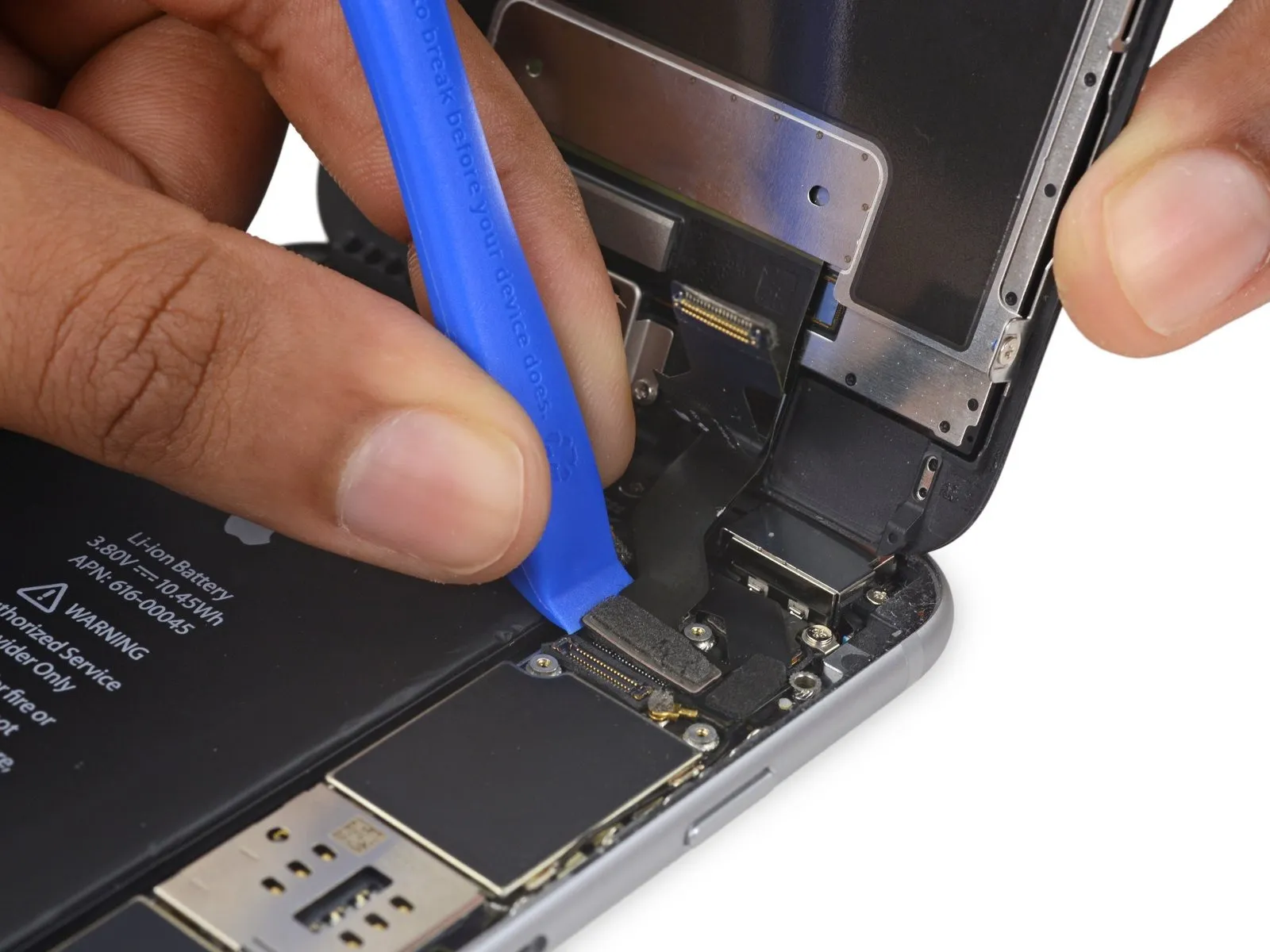

- Employ a plastic opening toolto release the digitizer cable, lifting it vertically away from its connection on the logic board.
- During reattachment of the digitizer cable, avoid applying pressure to its central area; instead, apply force to one edge, then the opposing edge. Central pressure can deform the connector and lead to digitizer damage.
Step 23

- Prior to detaching or reattaching the cable within this procedure, confirm the battery's power is completely inhibited.
- To release the home button/fingerprint sensor cable, apply upward force directly to it, separating it from its connection point on the logic board.
Step 24
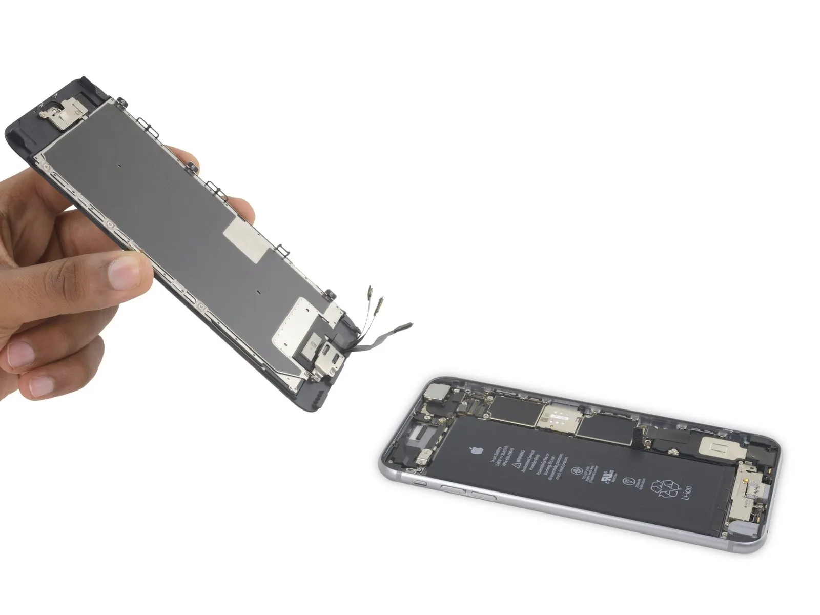
- Detach the display unit from the device.
- When putting the device back together, halt at this stage should you decide to substitute the adhesive securing the display's perimeter.
Step 25 | Home Button Assembly

- Detach the home button bracket by eliminating the two 1.9 mm Phillips screws that hold it in place.The bracket is fastened with two 1.9 mm Phillips screws.To release the home button bracket, you must first unscrew the two 1.9 mm Phillips screws.
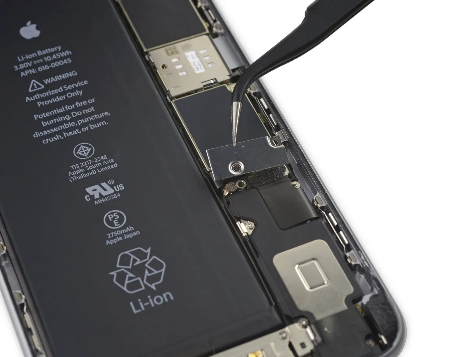
Step 26
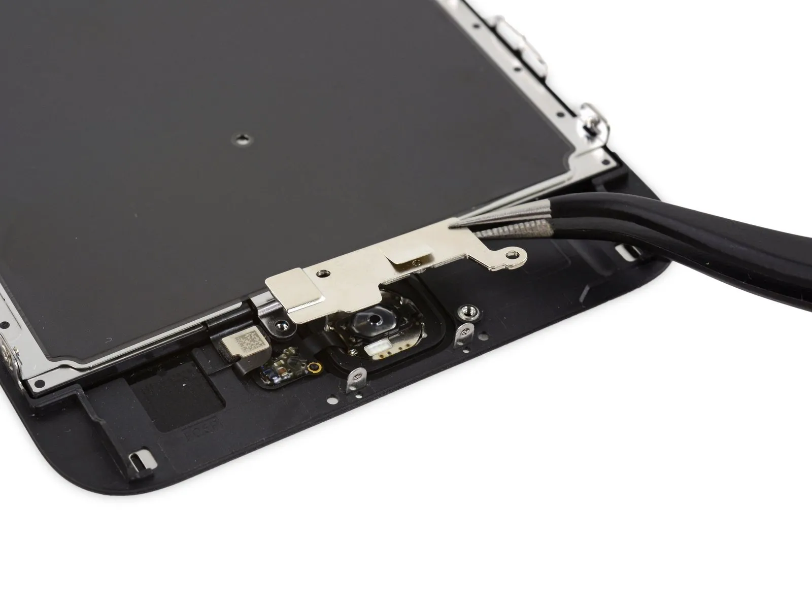
- Carefully detach the securing bracket that holds the home button in place.
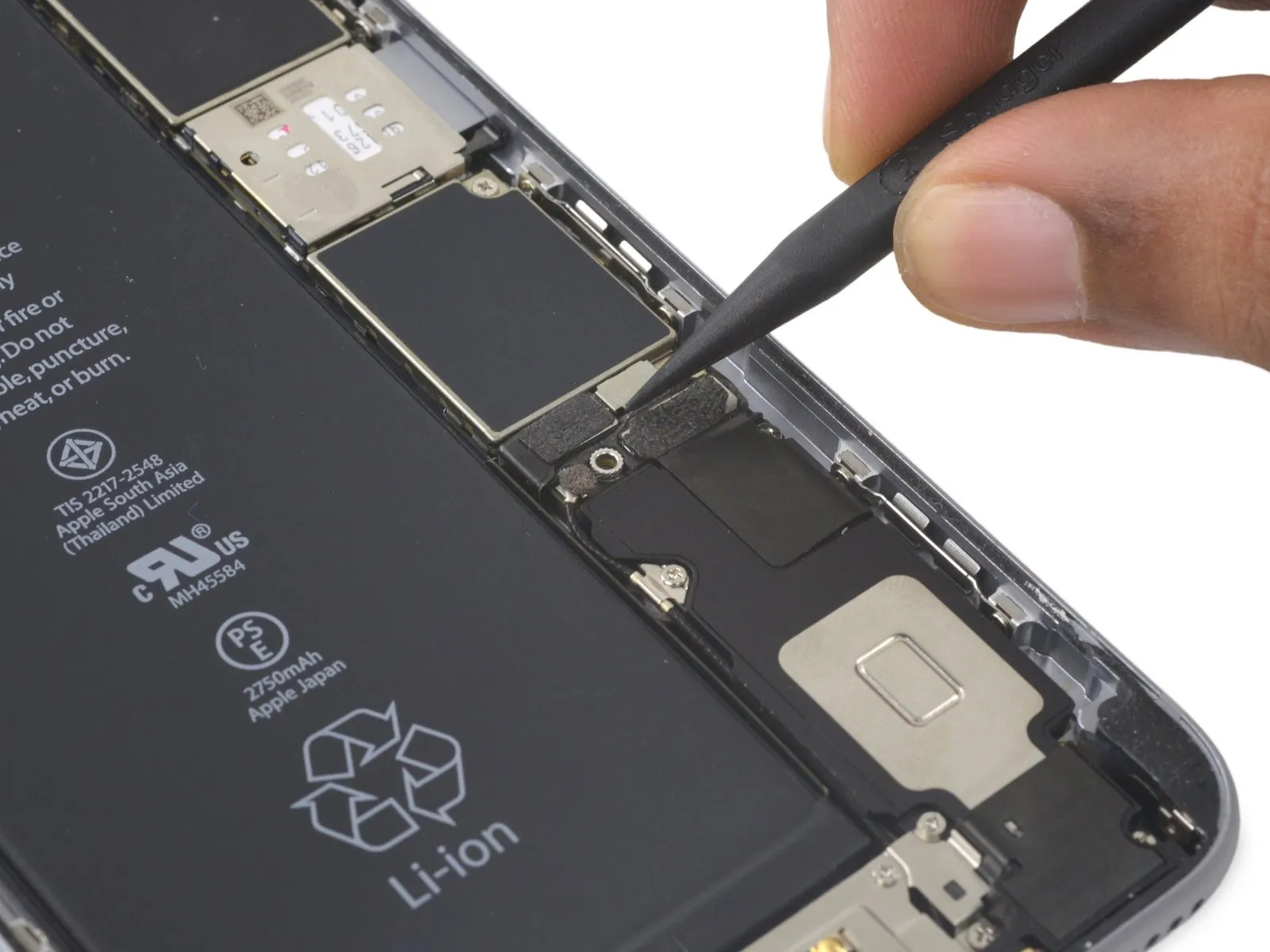
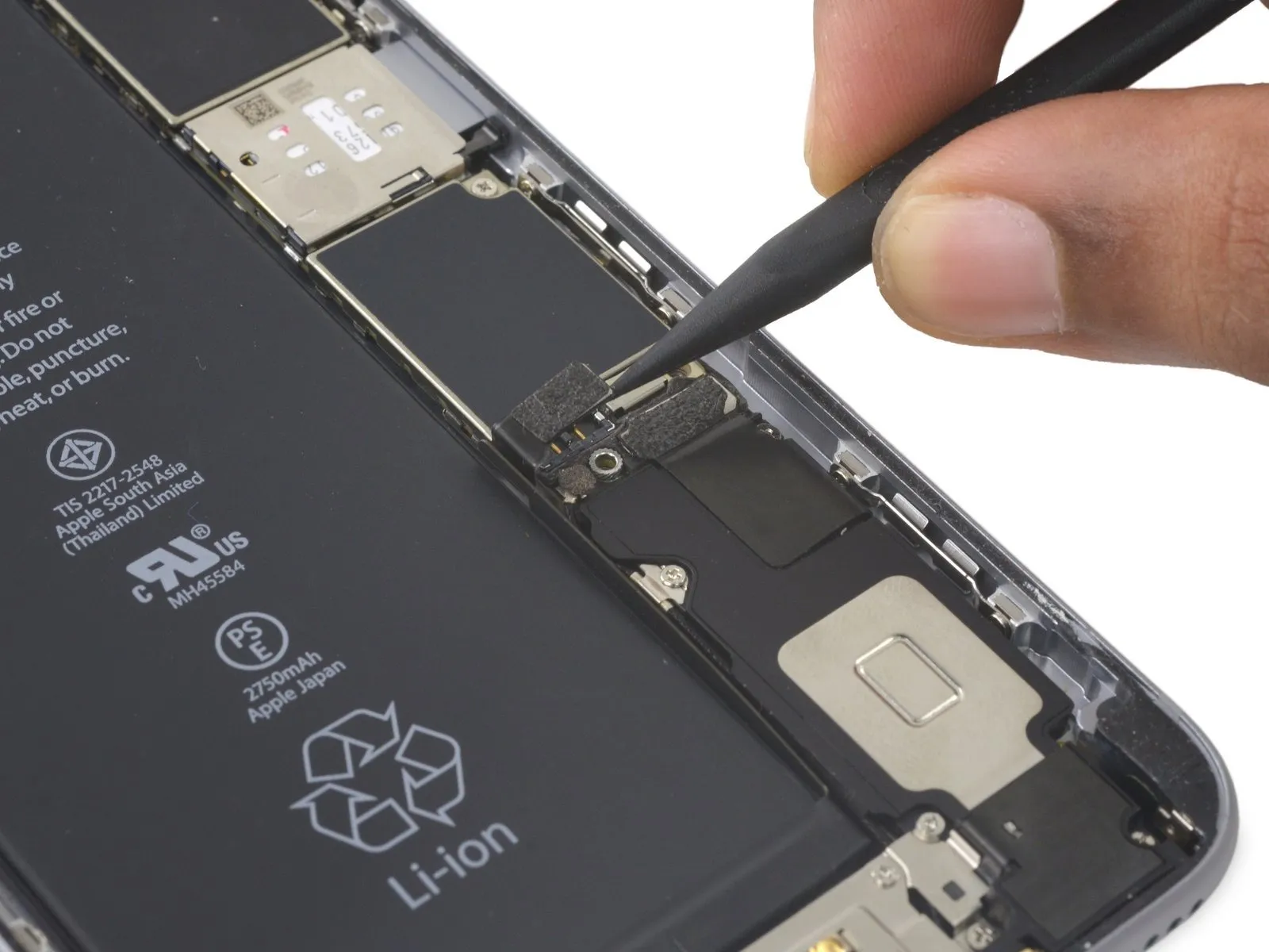
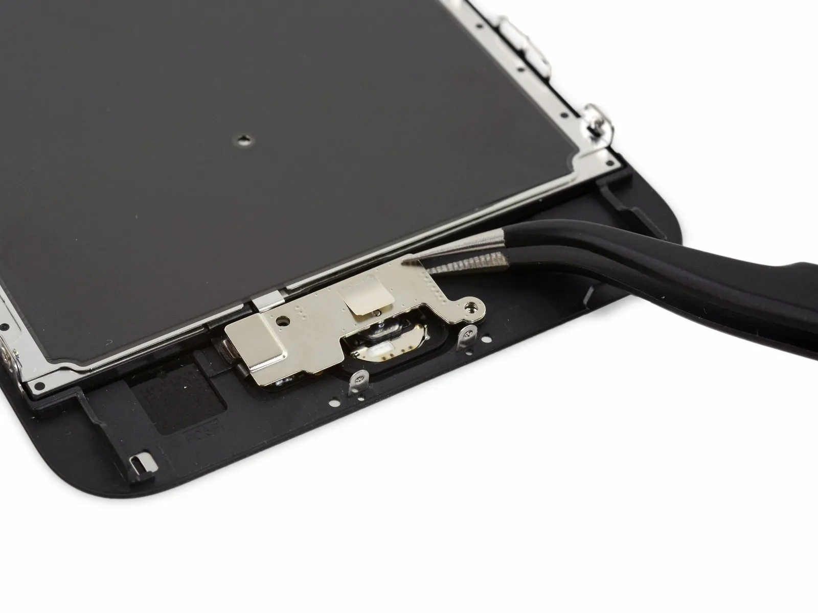
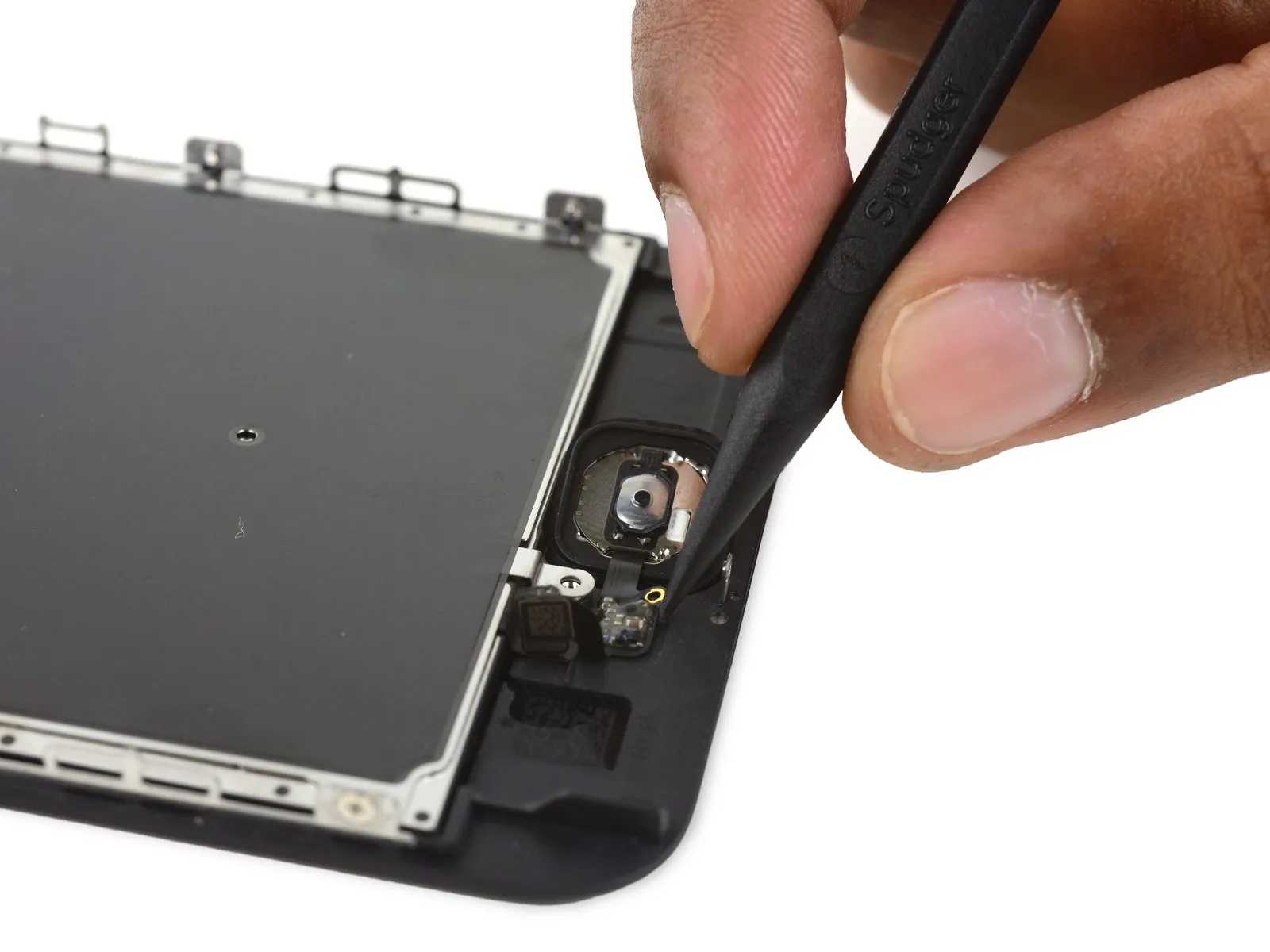
Step 27

- Carefully detach the home button cable's connection from its corresponding connector on the display assembly, utilizing the tapered end of a spudger.
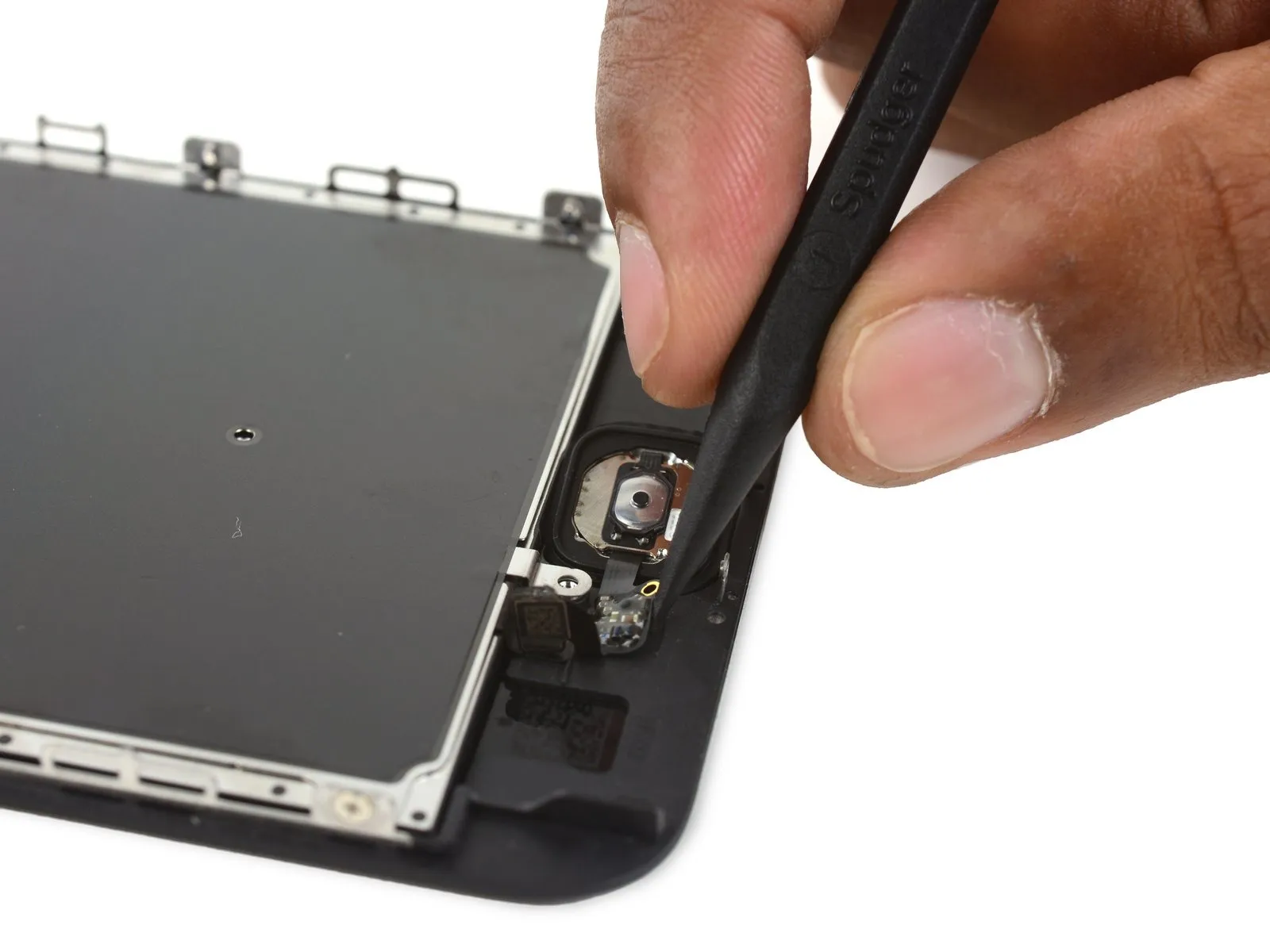
Step 28
- Due to its minimal thickness, the rubber gasket located around the home button is prone to damage and tearing.
Introduce a moderate amount of warmth, approximatelyan iOpener, aheat gun, or ahair dryer) to reduce the adhesive's strength that holds the home button gasket in place.
With your fingertip, exert a controlled upward force on the home button's surface, originating from the display assembly's front side; maintain consistent pressure to gradually detach the rubber gasket from the front panel.
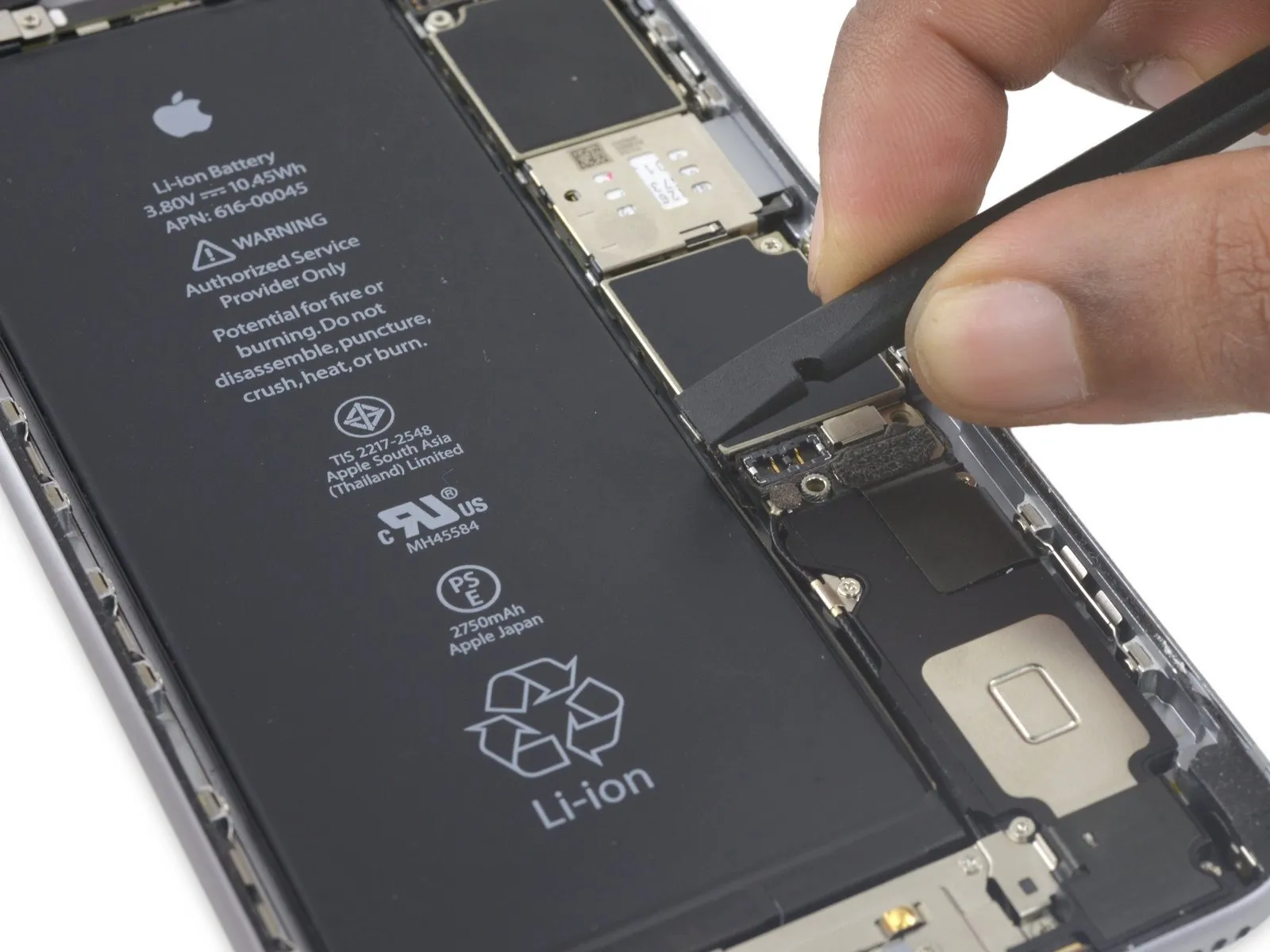
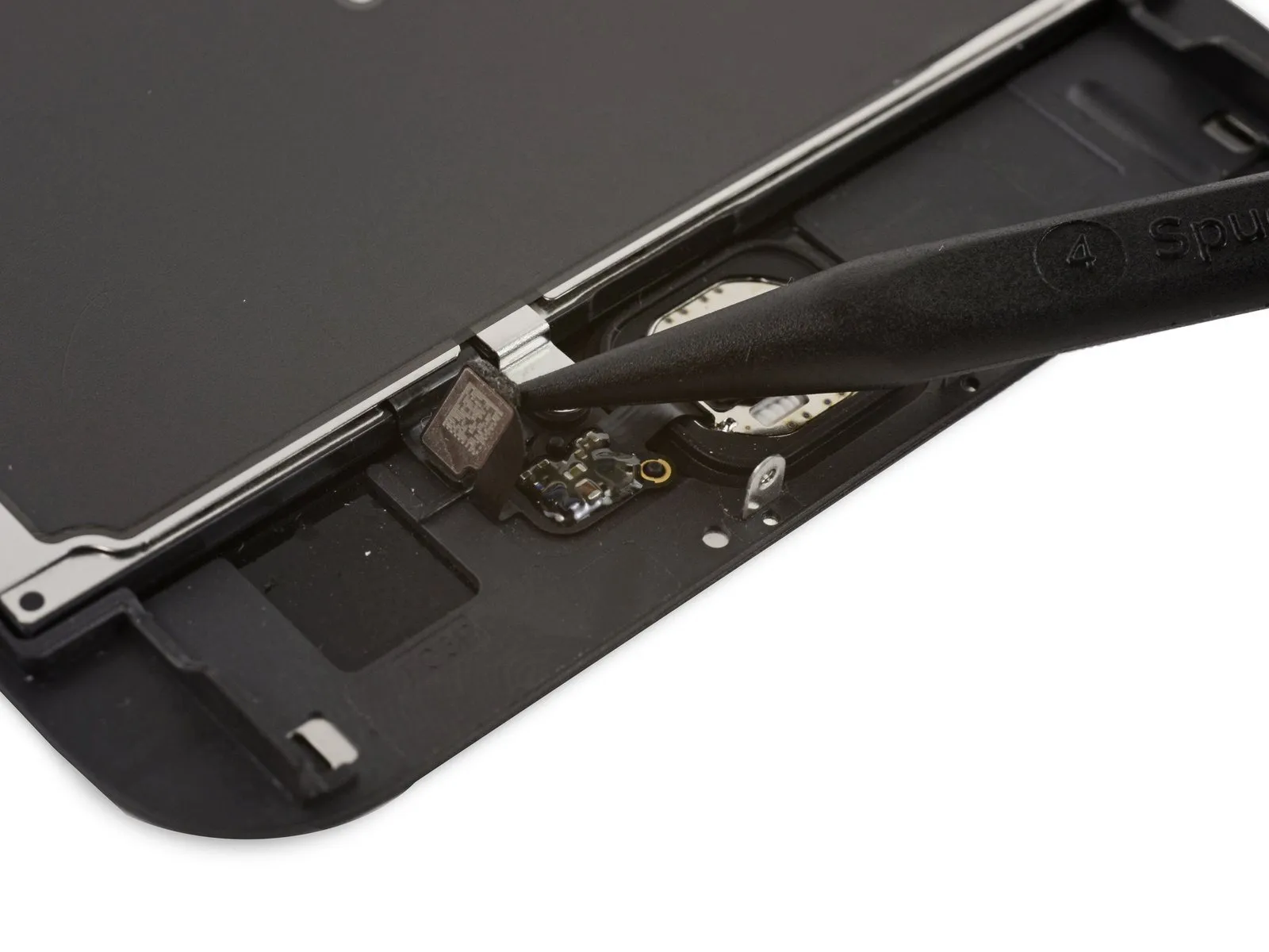
Step 29
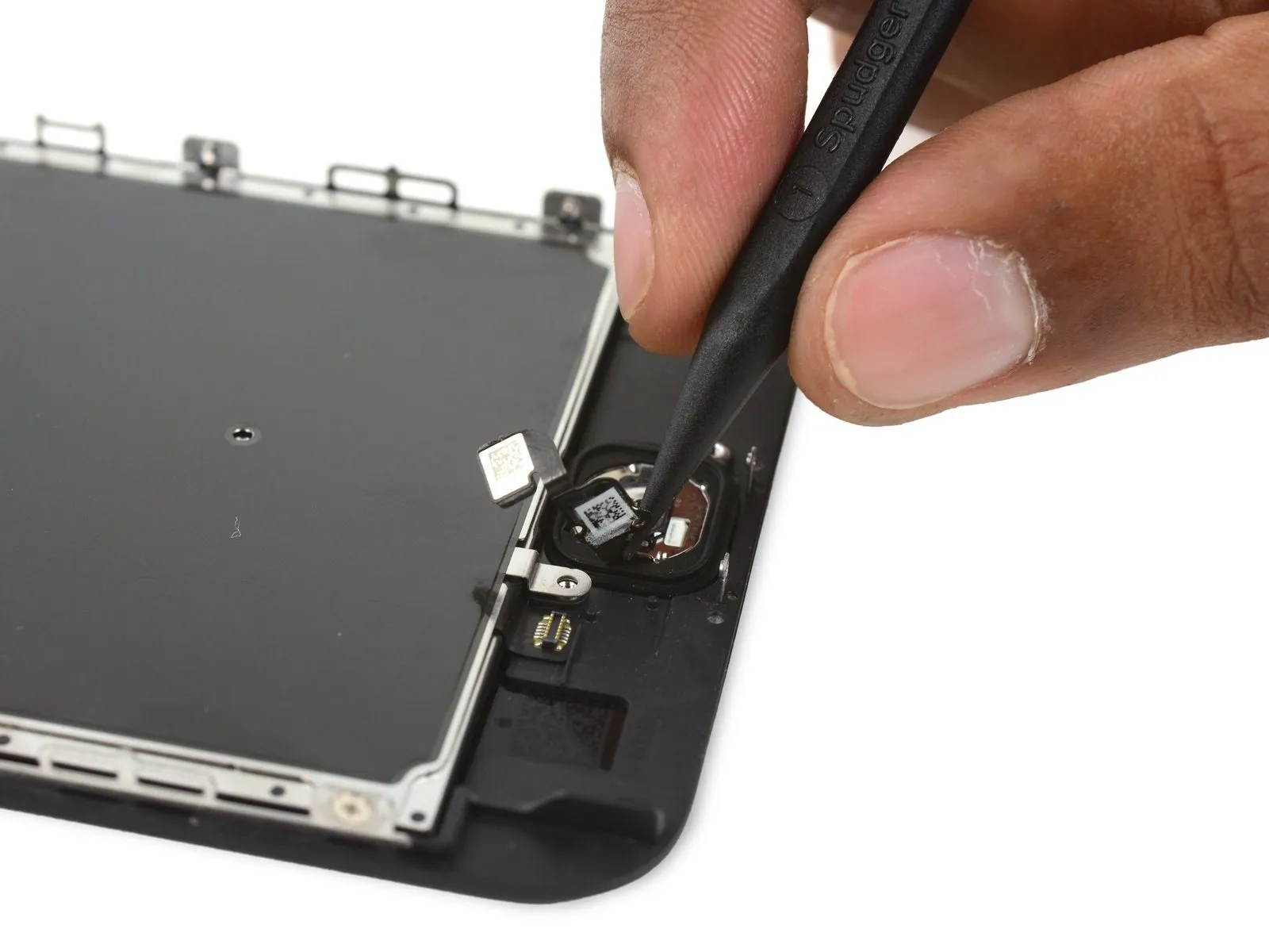
- Employ the tapered tip of a spudgerto carefully separate the gently-attached home button flex cable from the display assembly.
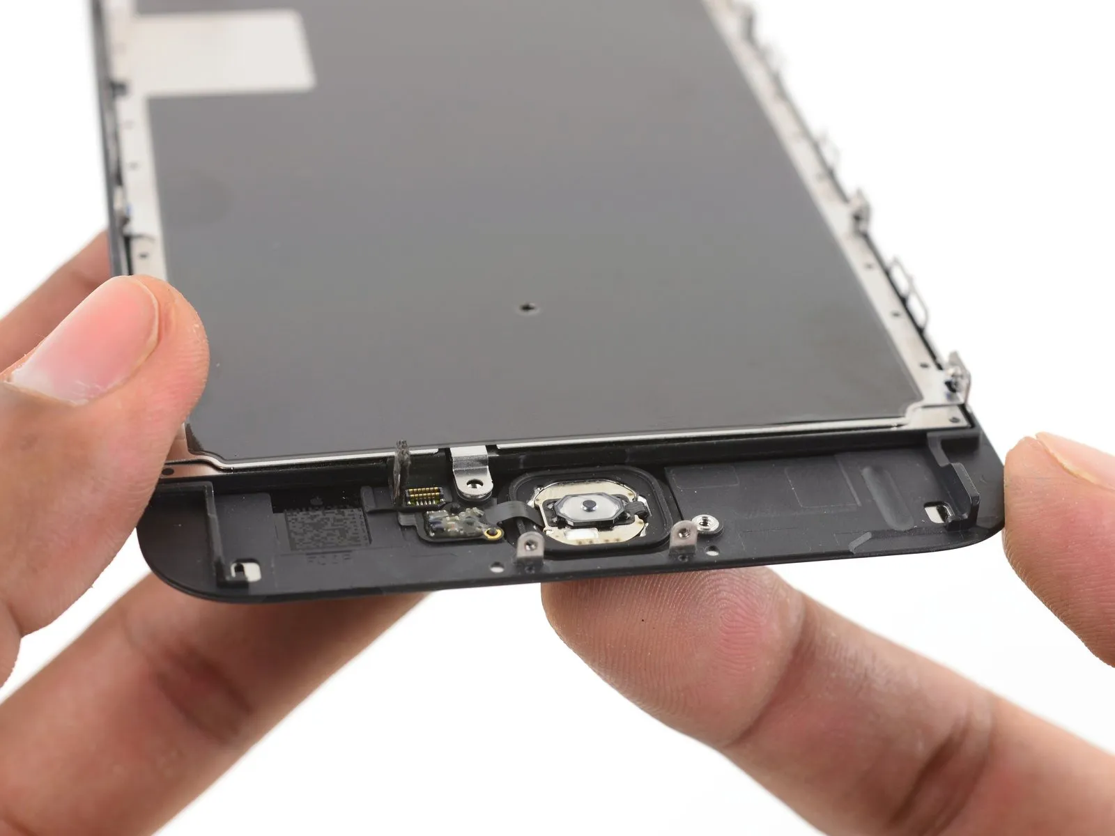
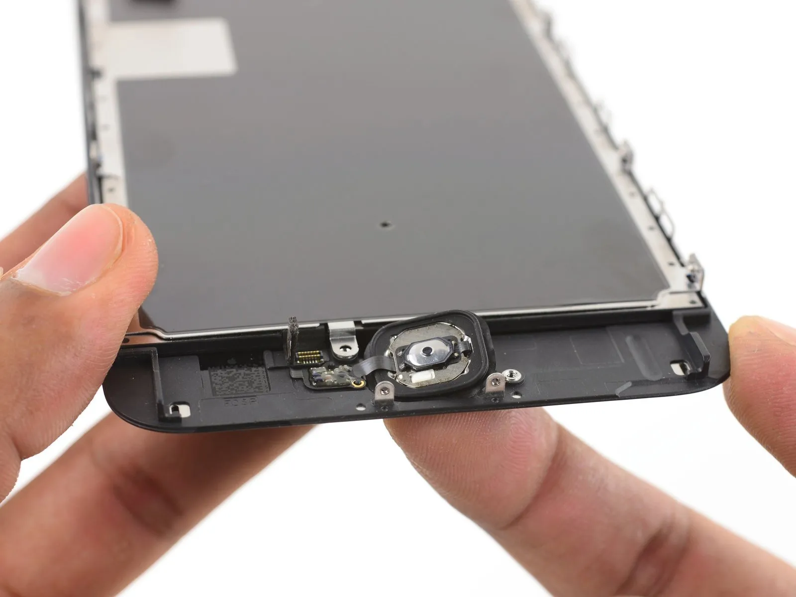
Step 30

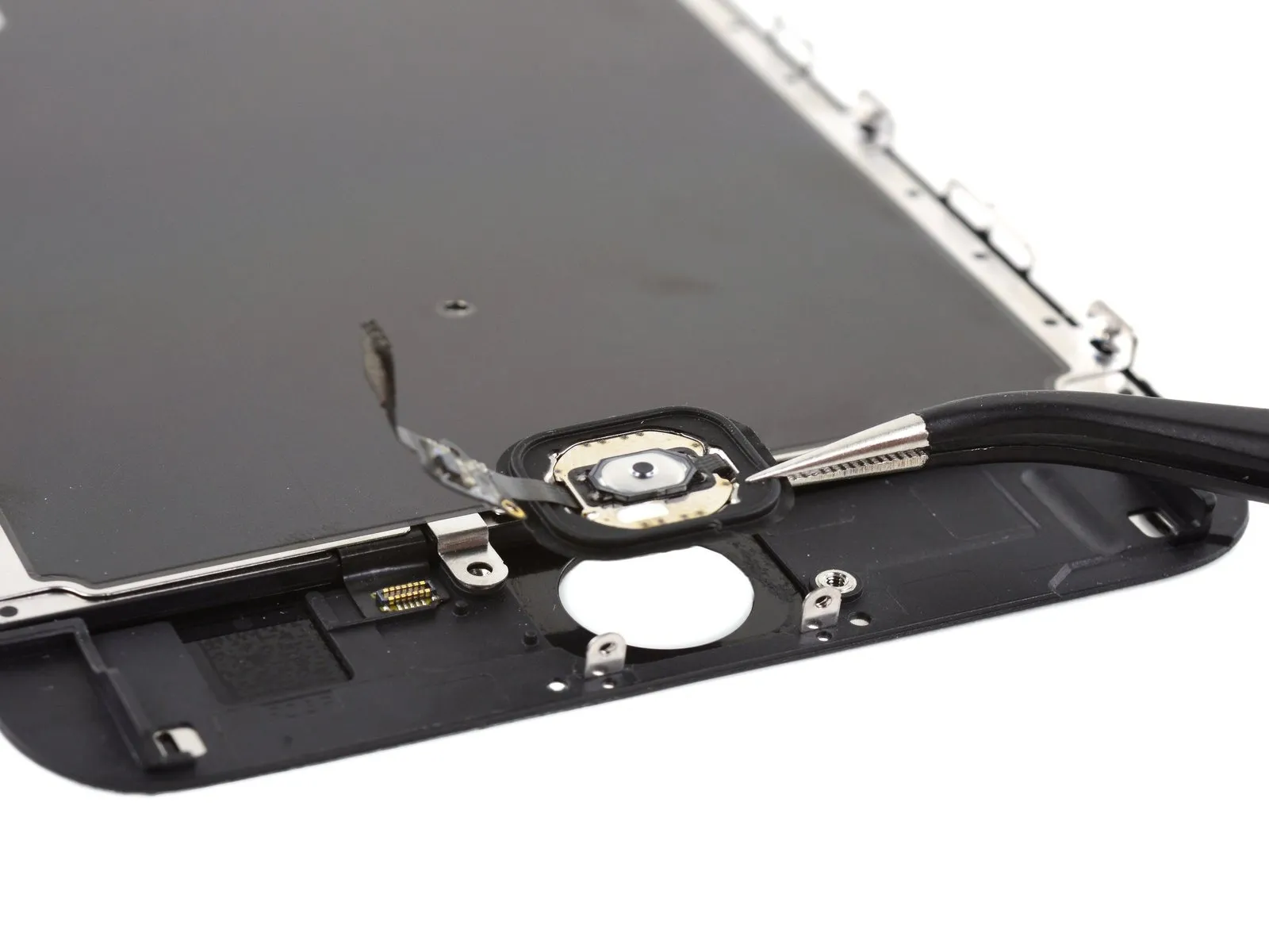
- Detach thehome button assembly.