iPhone 6s Plus Lightning Connector and Headphone Jack Replacement
To substitute the lower flex cable within an iPhone 6s Plus, adhere to the procedures detailed in this instructional document; this cable incorporates the headphone jack andLightning connector.Lightning port experiencing charging difficulties or USB connectivity problems, or if the headphone jack is unstable, component replacement may correct the malfunction.
- Furthermore, this guide can be utilized to replace theLightning connector bracket.
Step 1 | SIM Tray


- Apply pressure to the tool to release and extract the SIM tray.
Step 2

- Ensure the SIM eject aperture faces downward during reinsertion of the SIM tray.
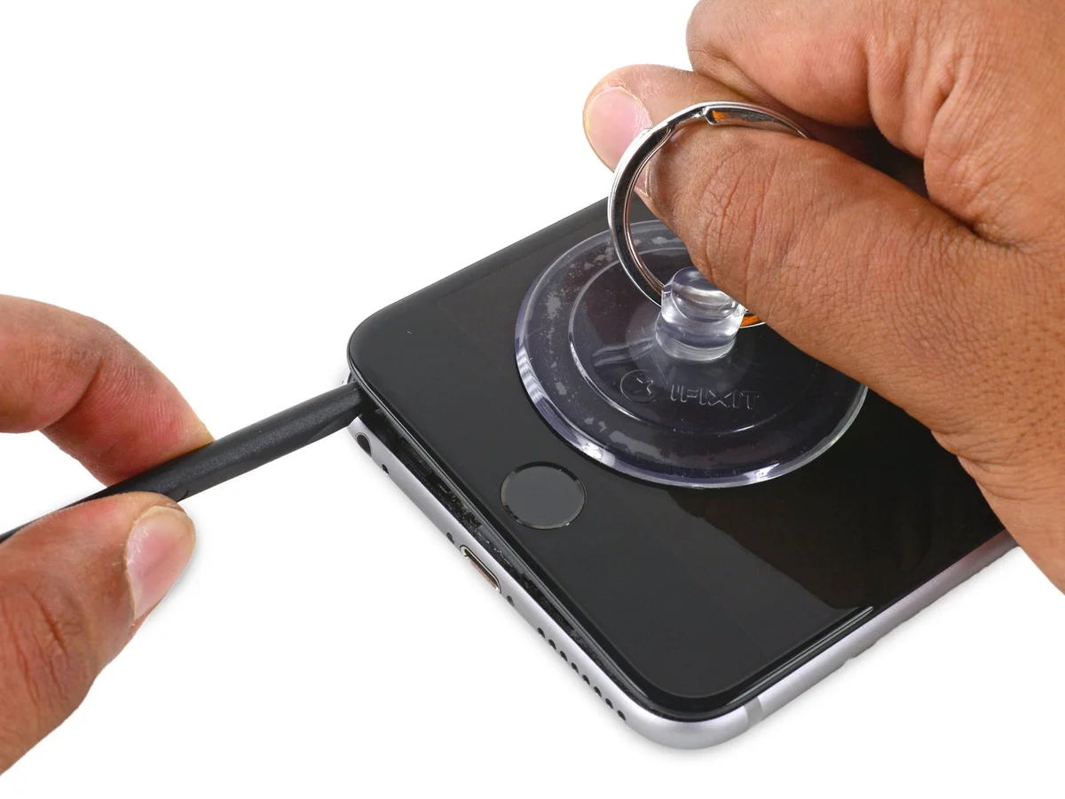
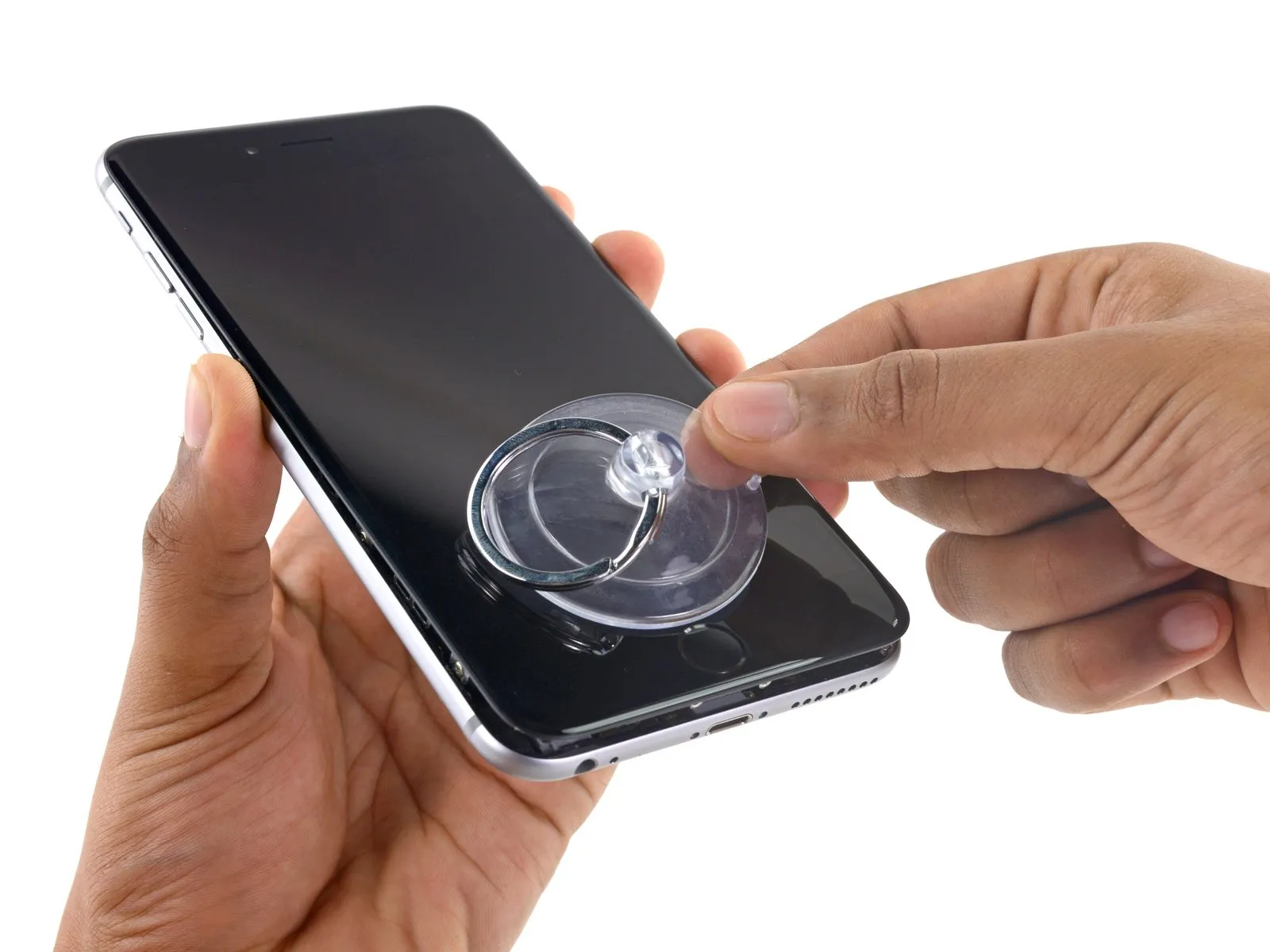
Step 3 | Pentalobe Screws
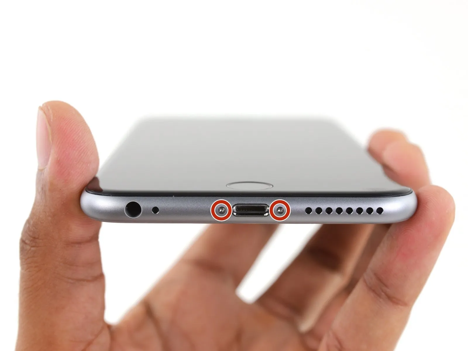
Deactivate the iPhone by powering it down completely before starting the disassembly process.
Begin the disassembly by eliminating the pair of 3.4-millimeter Pentalobe screws located on both sides of the Lightning connector.
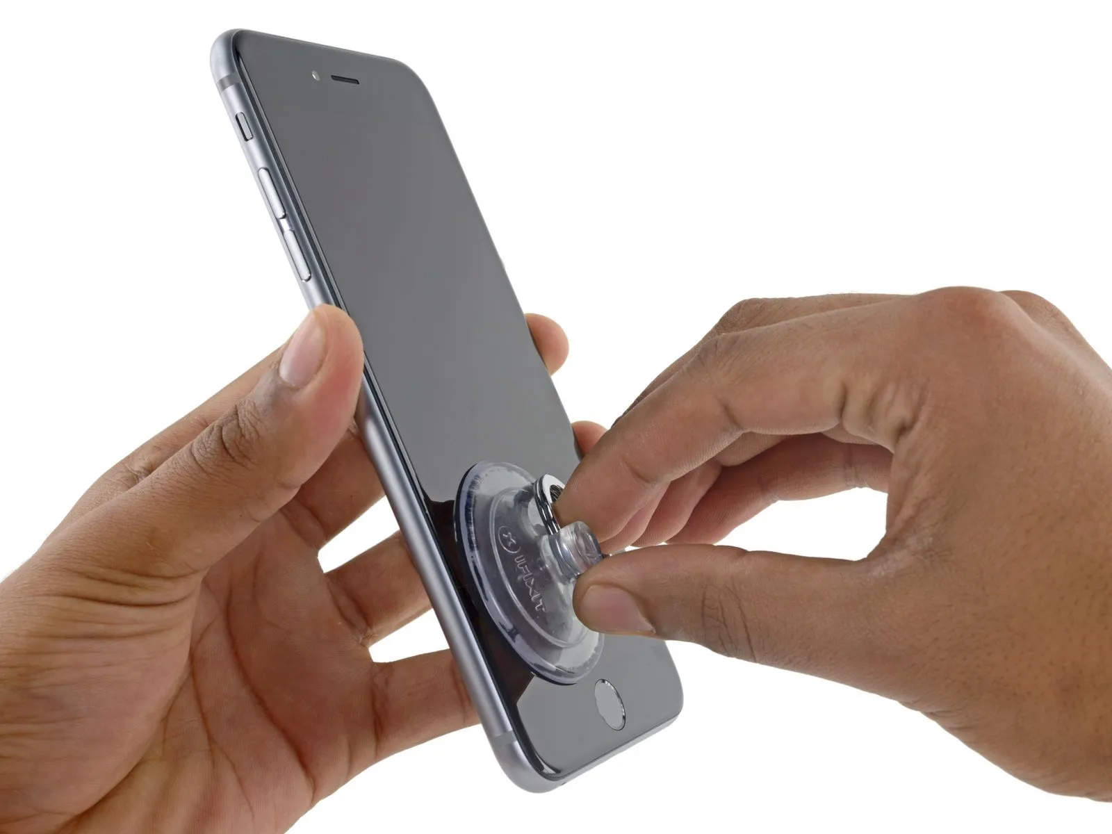
Step 4 | Anti-Clamp instructions


Detailed guidance on operating the Anti-Clamp, can be found in this separate document.
- To release the locking mechanism, retract the blue handle on the Anti-Clamp, allowing its arms to move freely.
- Carefully position the arms across either the left or right side of your iPhone.
- Place the suction cups close to the lower edge of the iPhone, situated directly above the home button; one cup should be on the front surface, and the other on the rear.
- Apply pressure by compressing the cups together to establish a secure suction bond to the intended area.
- In cases where the iPhone's surface exhibits excessive slipperiness, hindering the Anti-Clamp's ability to maintain grip, applying adhesive tape can provide a more textured surface for improved adhesion.
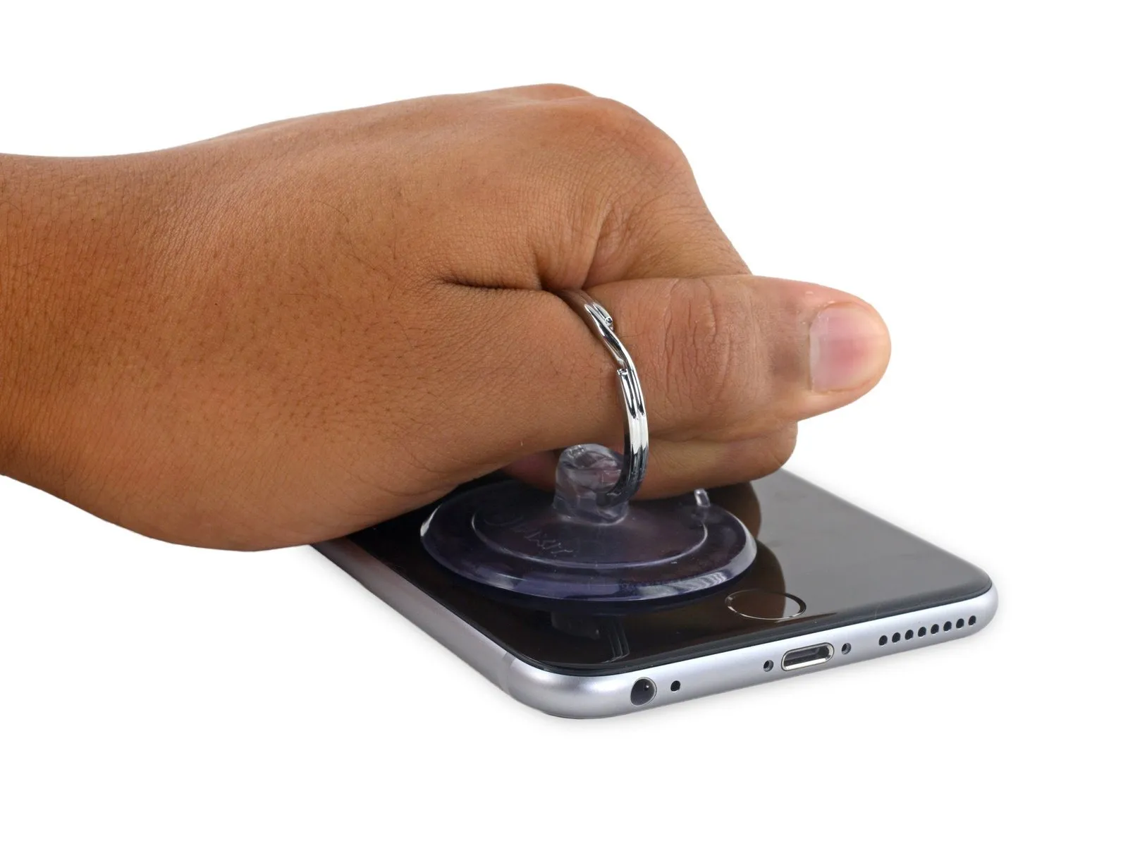
Step 5


- Rotate the handle clockwise a full revolution, or until the suction cups begin to deform.
- Confirm that the suction cups maintain their parallel orientation; should they deviate, slightly release the suction cups and readjust the arms.
- Introduce an opening pick beneath the display assembly once the Anti-Clamp has generated a noticeable separation.
- Should the Anti-Clamp fail to produce an adequate gap, rotate the handle by 90 degrees.
- Avoid rotating the handle beyond a 90-degree increment at any point, and allow several seconds to elapse between rotations, permitting the Anti-Clamp and time to facilitate the separation.
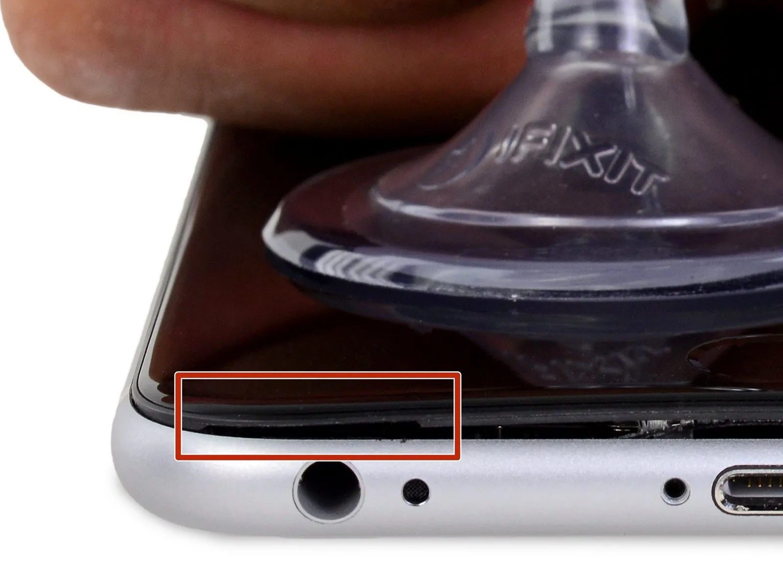
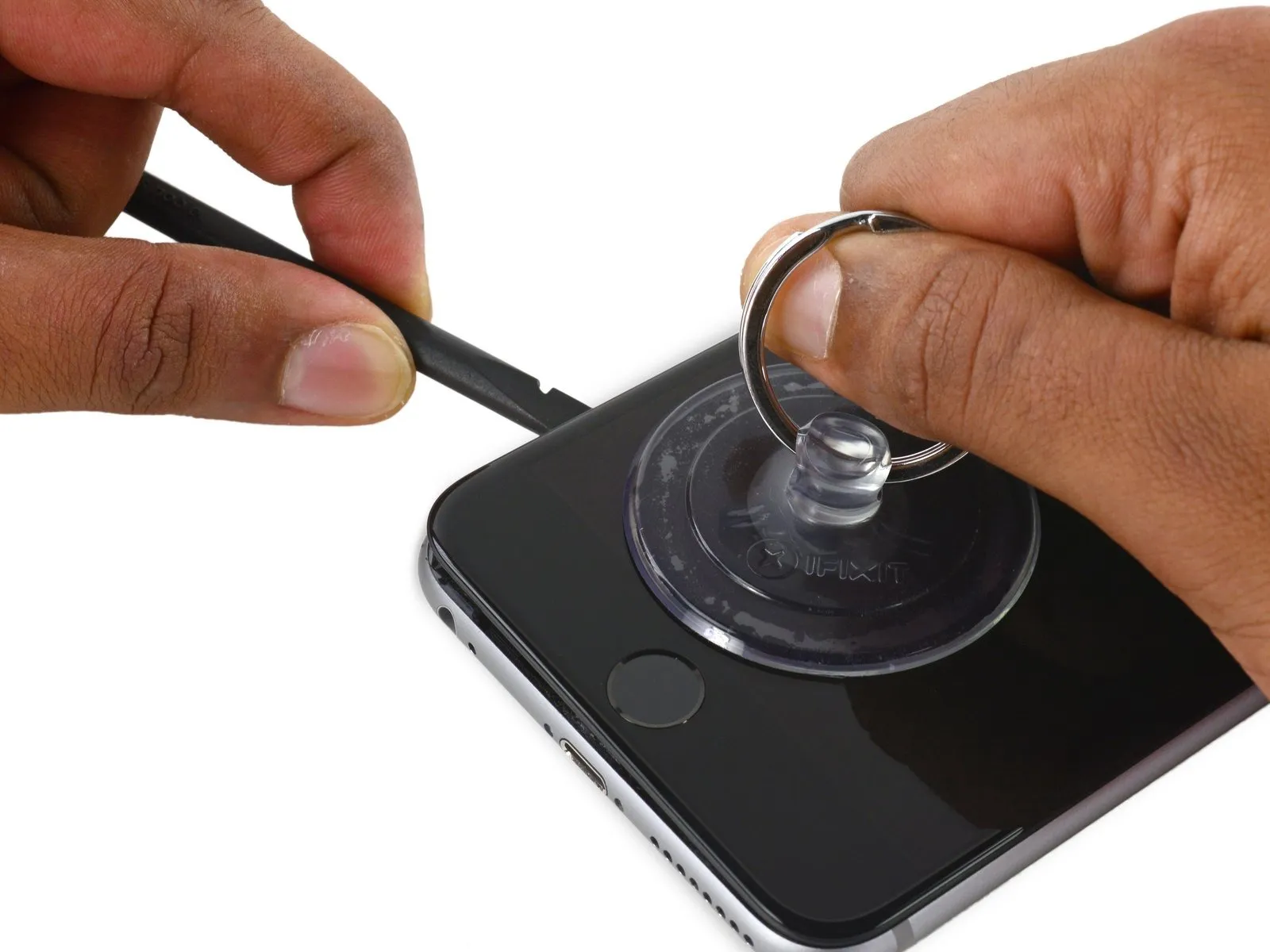
Step 6 | Opening Procedure
- Introduce gentle warmth to the device's bottom border with either an iOpener or a hair dryer, maintaining this application for approximately sixty seconds.
- The purpose of this heating process is to reduce the adhesive's strength, which holds the display in place, thereby simplifying the opening procedure.
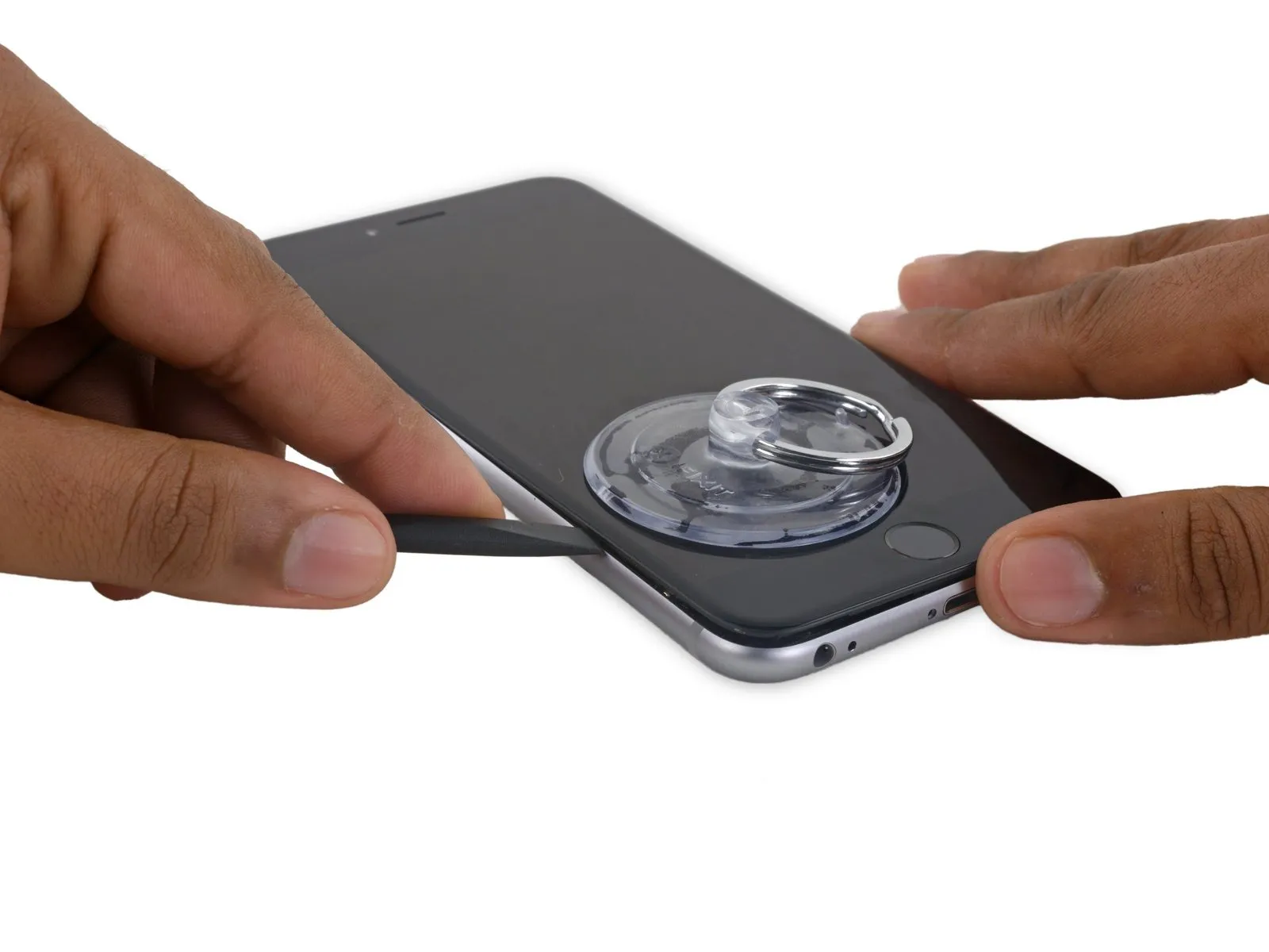
Step 7
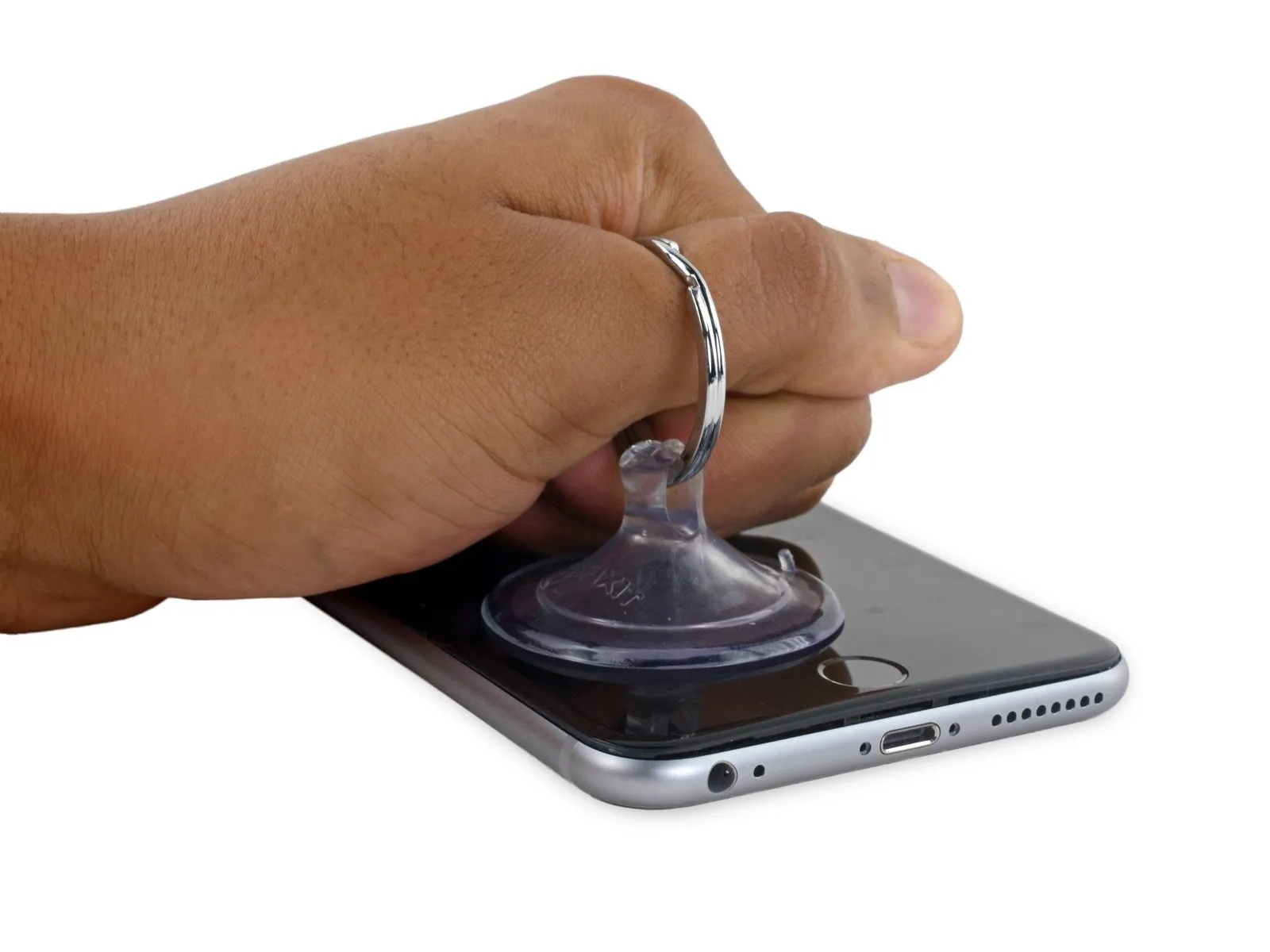
- Secure a suction cup to the lower-left portion of the display assembly.
- In cases where the display exhibits severe cracking, applying a layer of transparent packing tape can facilitate the suction cup's grip; alternatively, a robust adhesive tape can substitute for the suction cup. As a last resort, a small amount of superglue can be utilized to affix the suction cup to the fractured screen.
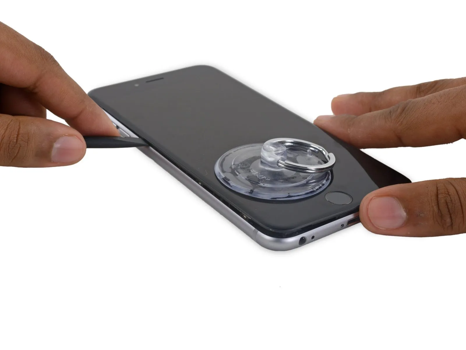
Step 8
- Excessive force during separation risks damaging the display assembly; therefore, use only the necessary pressure to establish a small separation between the display assembly and the rear case.
Step 9

- Continuing to apply consistent downward force with the suction cup, carefully slide the thin, wedge-shaped end of a spudger into the newly formed space, situated immediately above the headphone jack.
Step 10
- Utilize the spudger, rotating it to incrementally increase the separation between the front panel assembly and the rear enclosure.
Step 11


- Maintaining a secure grip on the suction cup by applying upward force, carefully insert the spudger's edge beneath the lower left corner of the display panel.
Step 12
- Carefully insert the spudger's pointed end along the left edge of the device, creating a separation between the display assembly and the back cover.
Step 13


- Employing the flat end of the spudger, carefully position it beneath the rightmost border of the display assembly.spudgerProceed to gently move the spudger upwards along the right-hand side of the display.
- Slide the spudger up the right side.
Step 14


- To prevent damage during separation, secure the rear enclosure with a plastic opening tool while employing a suction cup to lift and disengage the device.
- Avoid complete removal of the display assembly, as doing so risks compromising the delicate data cables situated along the upper portion of the iPhone.
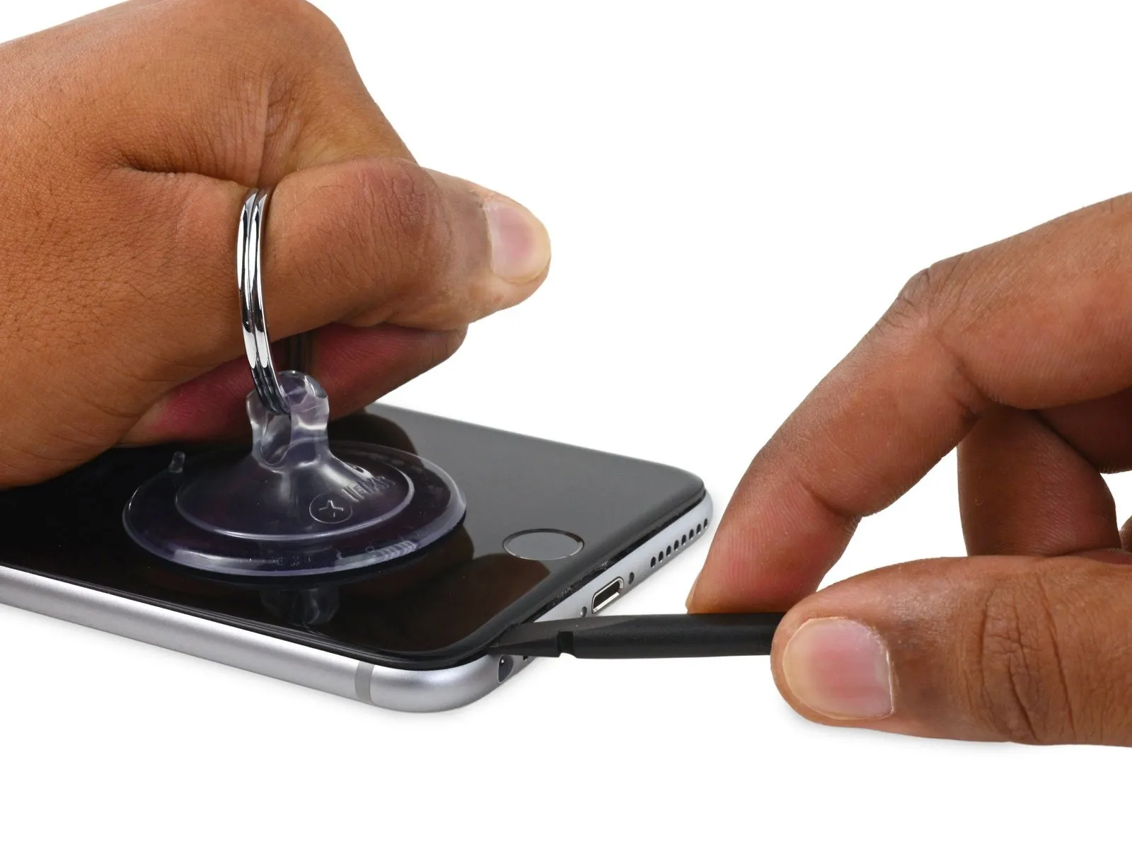
Step 15

- To detach the suction cup from the display surface, grasp the diminutive protrusion located on its body and exert an upward force.
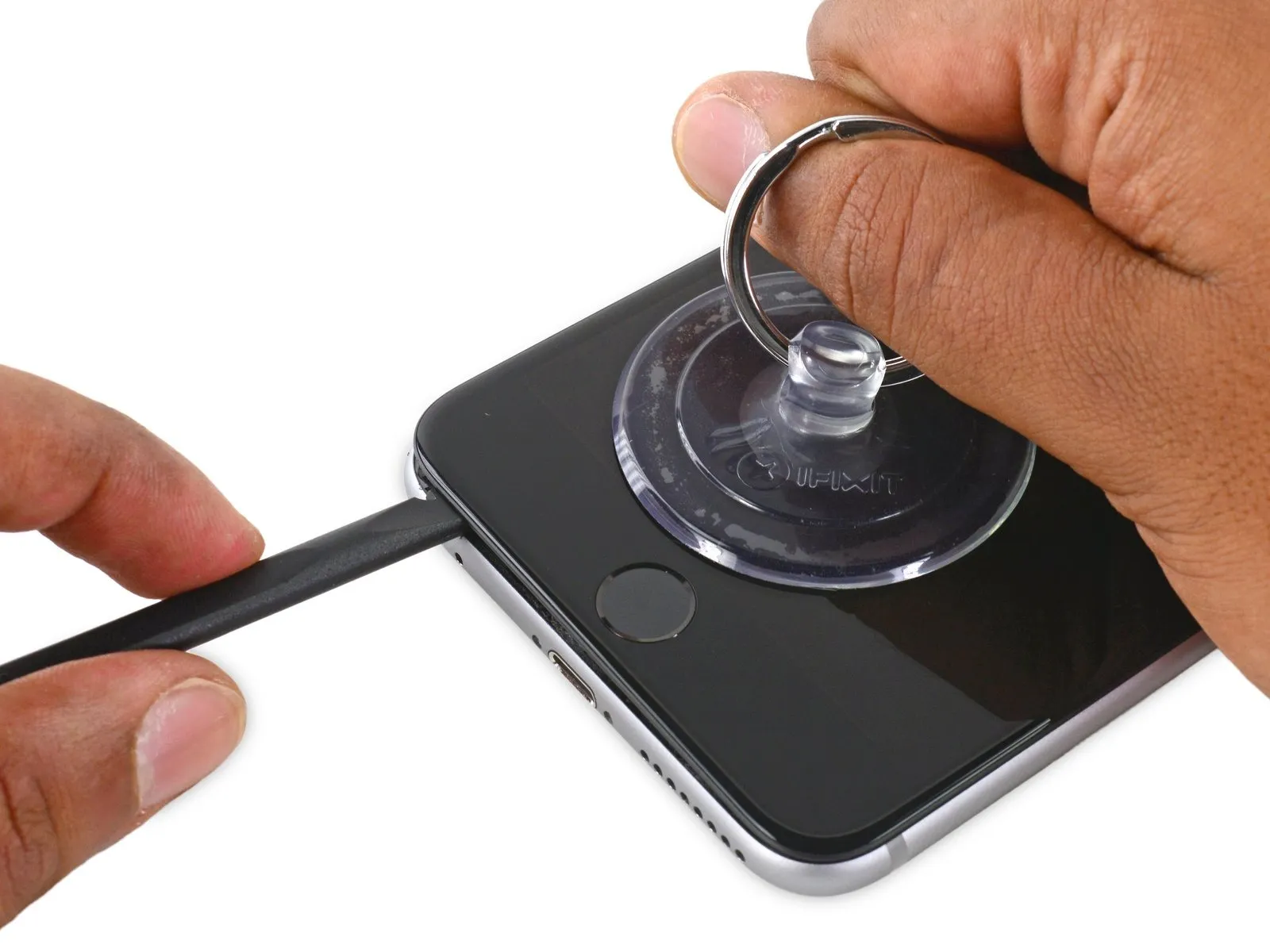
Step 16

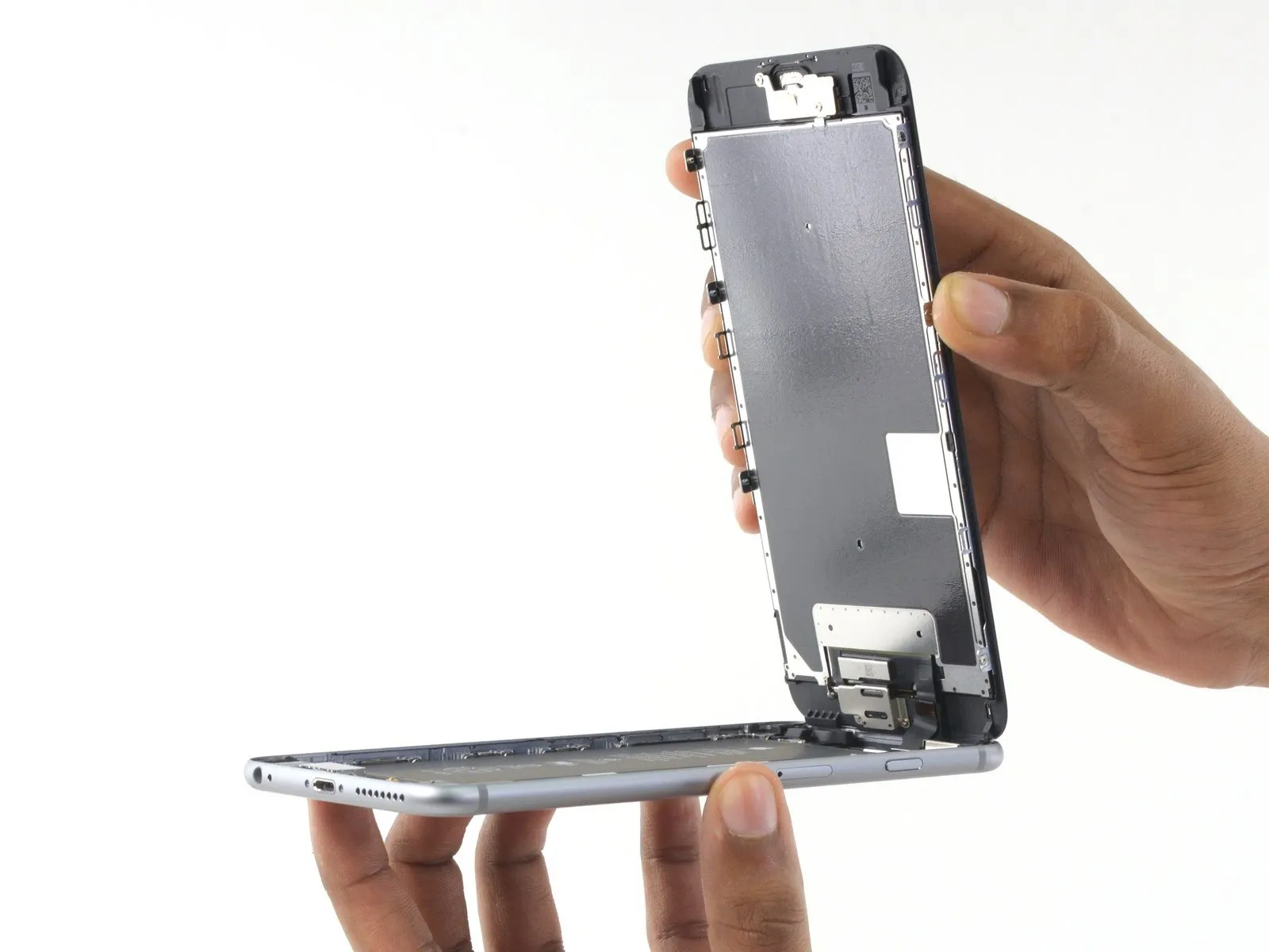

- Carefully hold the display assembly and raise it to initiate the phone's opening process, utilizing the clips located at the top edge of the front panel as a pivot point.
- Position the opened display at approximately a 90-degree angle and secure it with a support to maintain its position during the repair process.
- Avoid exceeding a 90-degree opening angle for the display, as it remains connected to the phone's upper section via the display cable, digitizer cable, and front camera cable, all of which are susceptible to damage.
- Employ a rubber band to firmly secure the display in its open position, thereby minimizing stress on the delicate display cables.
- As a temporary solution, an unopened, sealed beverage container can be used to provide support for the display.
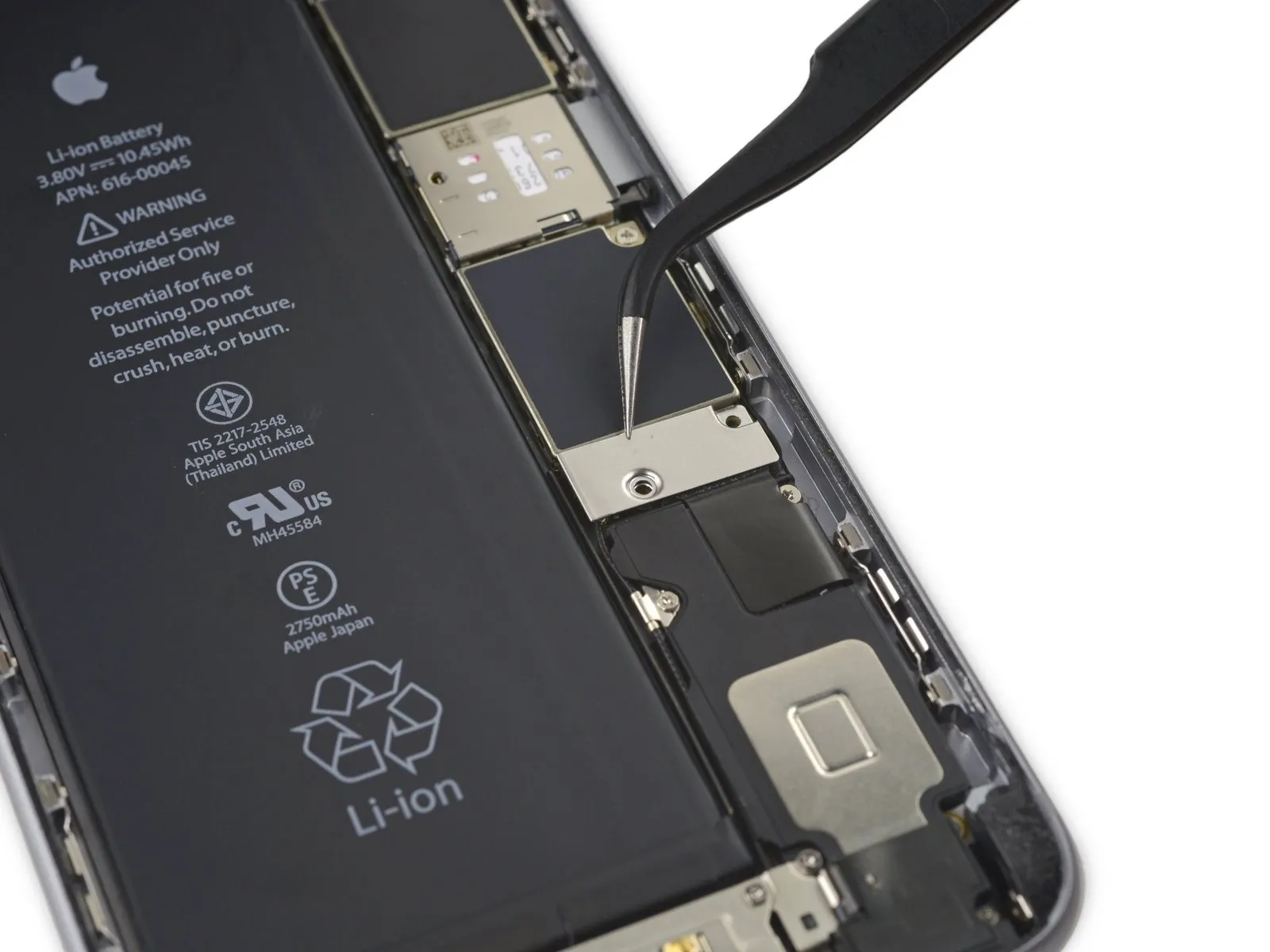
Step 17 | Battery Connector
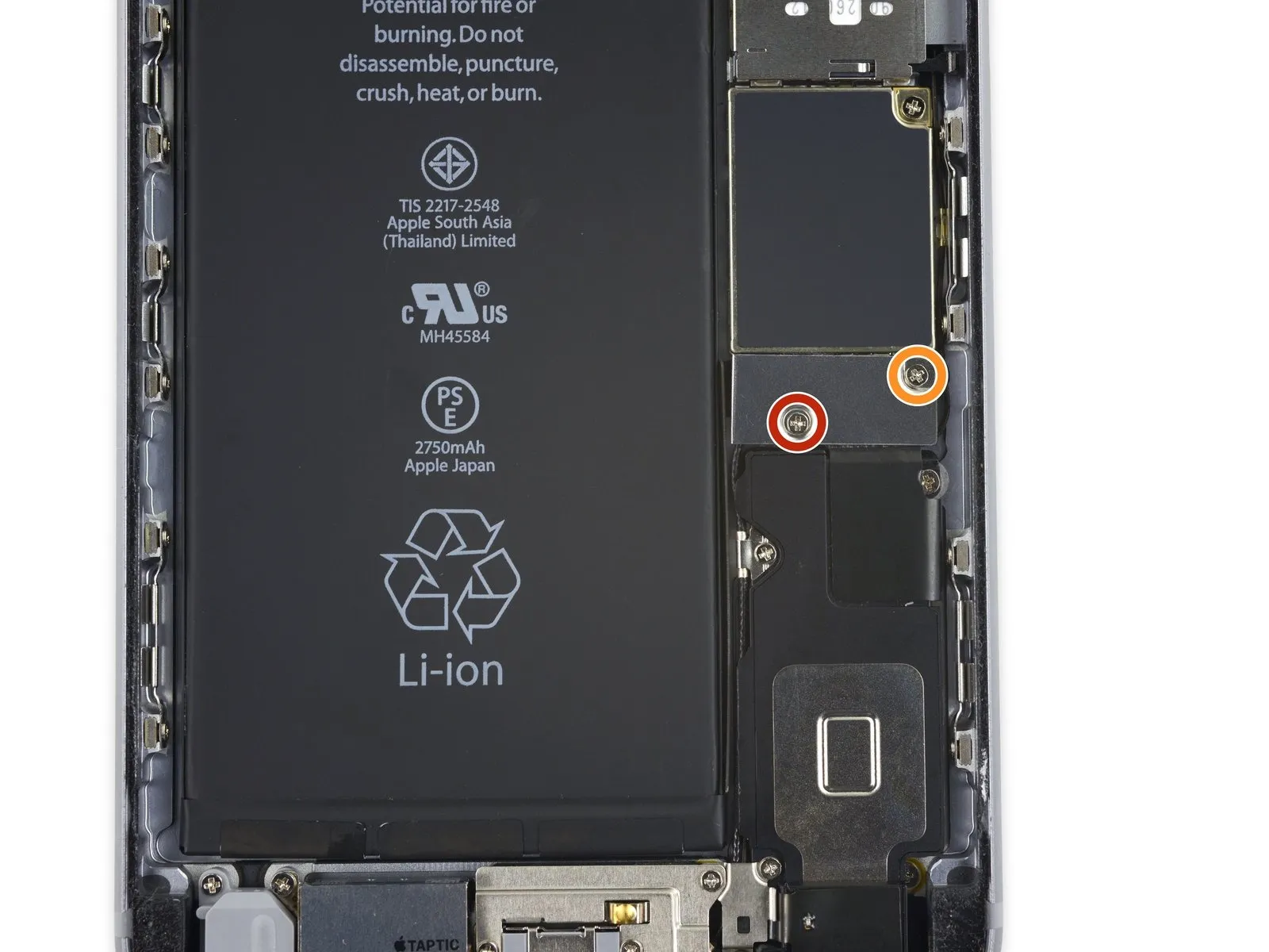
- A single 2.9 mm fastener is required.
- Additionally, a 2.3 mm fastener must be removed.
Step 18
Step 19

Step 20


Step 21 | Display Assembly
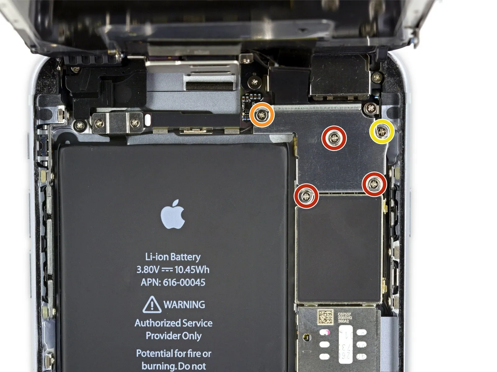
- To proceed with the repair, detach the listed Phillips screws.
- Three1.3millimeters
- One1.6millimeters
- One3.0millimeters
- When reassembling the device, ensuring the correct placement of this3.0millimetersscrew within the upper-rightmost position of the bracket is essential to prevent potential damage to the logic board.
Step 22

Step 23

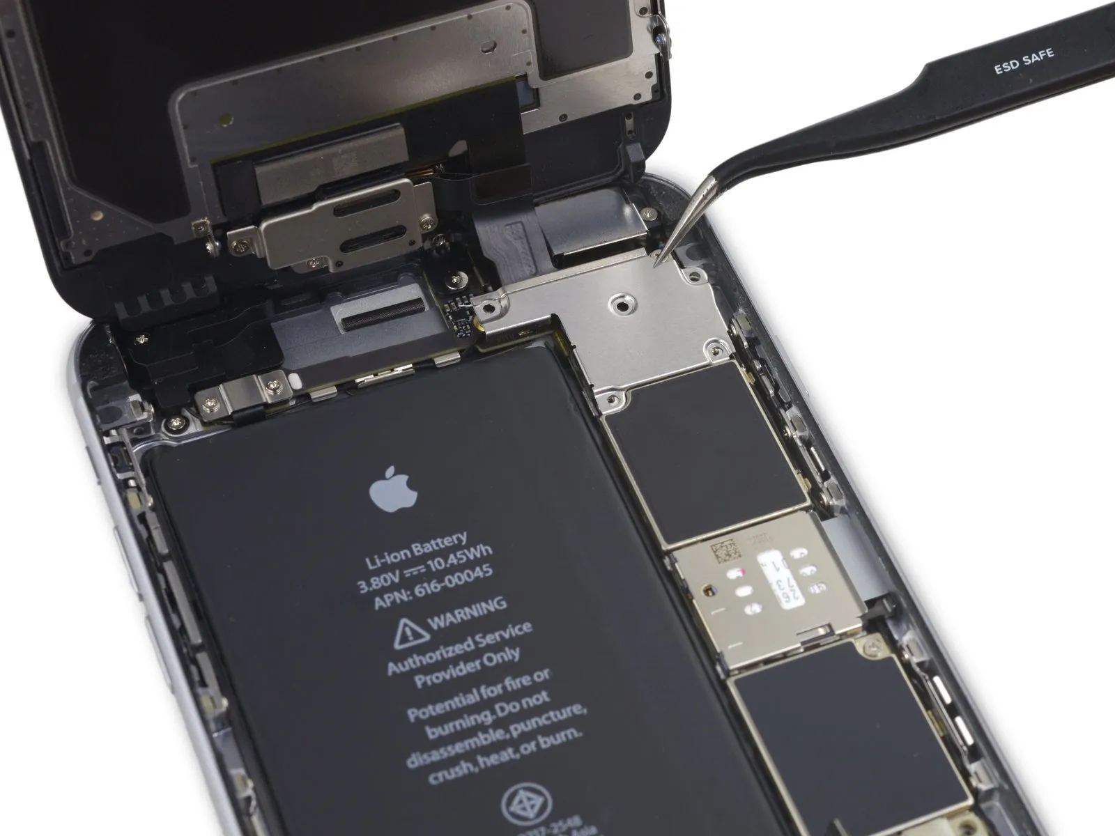
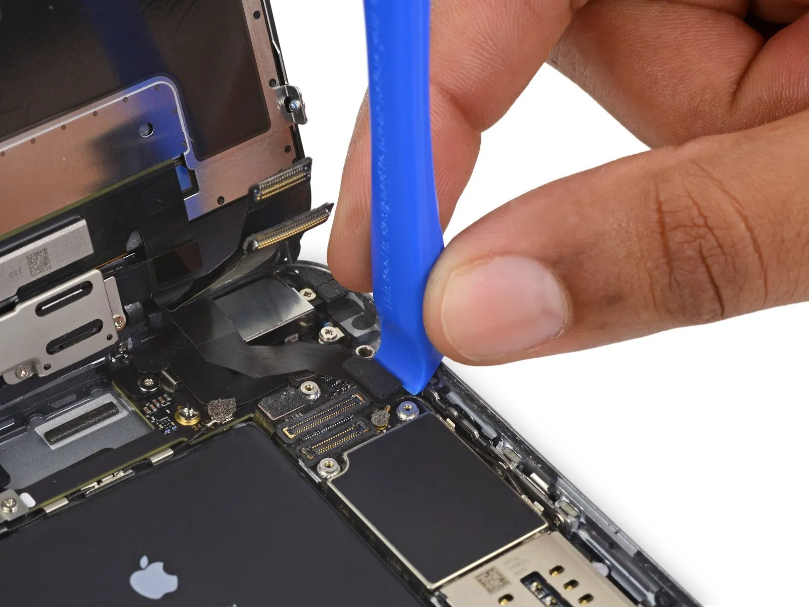
- Exercise caution, ensuring that prying force is applied solely to the connector body, avoiding damage to the socket situated on the logic board.
- Employ a plastic opening tool to carefully release the front-facing camera and sensor cable connector.
Step 24

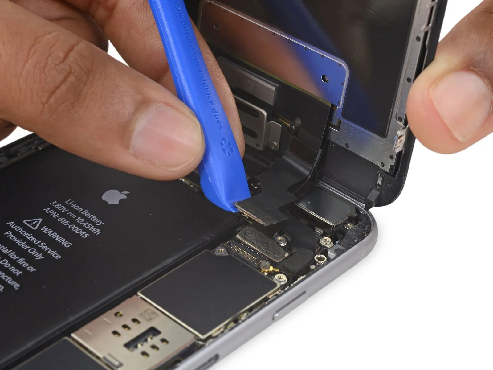
- Employ a plastic pry tool to release the digitizer cable, lifting it vertically from its connection on the logic board.
- During reattachment of the digitizer cable, avoid applying pressure to the connector's central area; instead, secure one end, followed by the opposite end.Central force on the connector risks bending the internal structure, potentially leading to digitizer malfunction or damage.
Step 25

- Prior to detaching or reattaching the cable within this procedure, confirm the battery's power is completely removed.
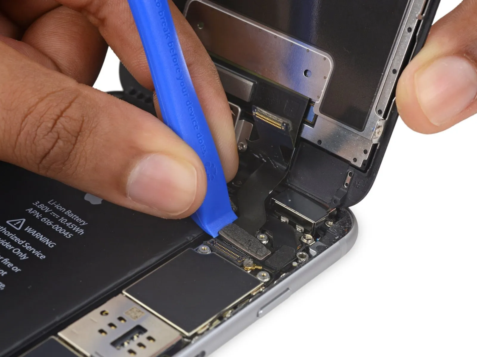
- To release the home button/fingerprint sensor cable, carefully lift it vertically away from its connection point on the logic board.
Step 26
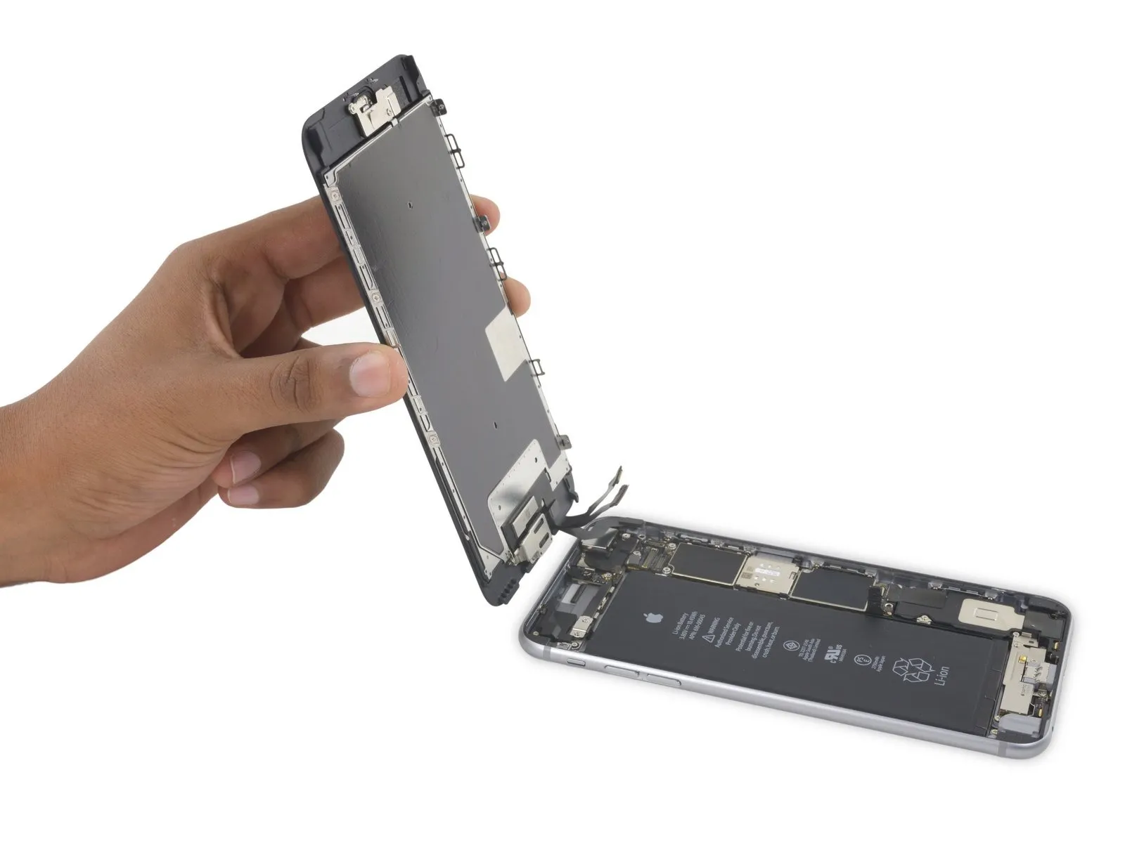
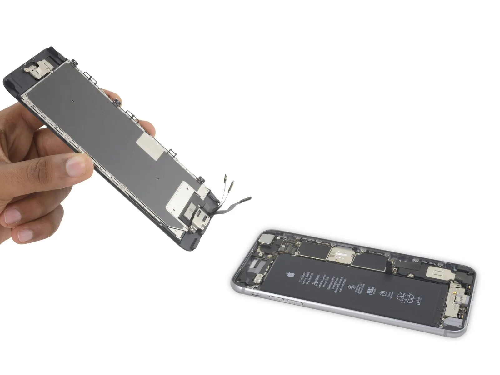
- Detach the display assembly from the device.
- When putting the device back together, halt at this point should you desire to substitute the adhesive that seals the display's perimeter.
Step 27 | Speaker

Employing the tip of a spudger, carefully lift and detach theantenna cable situated on the underside of the logic board.
Step 28

Employing the tip of a spudger, carefully lift and detach theLightning connector cableto release it from its connection on the logic board.
Step 29

- To detach the Lightning connector bracket, first eliminate the three Phillips head screws that hold it in place.
- The bracket is fastened with two screws, each measuring 3.5 millimeters in length.
- A single screw, with a length of 2.7 millimeters, is also used in the assembly.
- Following screw removal, the bracket can then be taken off.
Step 30


Employ the tip of a spudgerto carefully lift and detach the antenna cable from the Lightning connector assembly.
Step 31
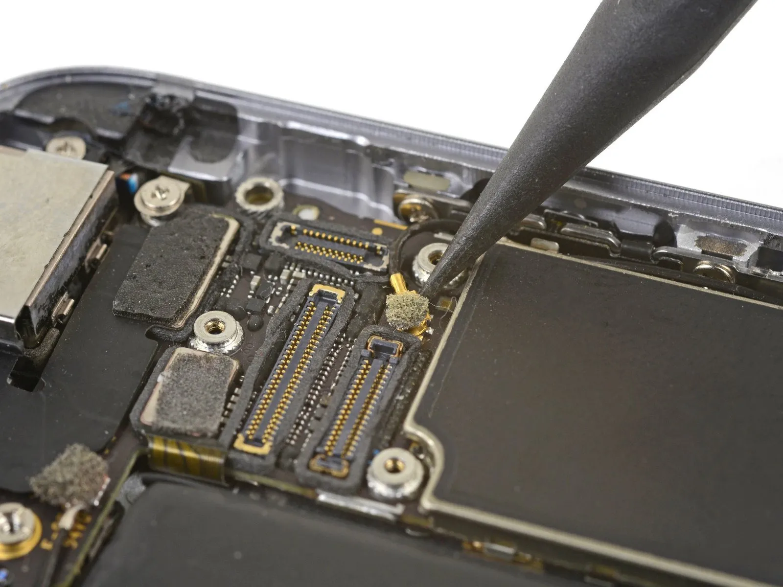

Employ the tip of a spudgerto carefully lift and detach the antenna cable connector from the logic board's uppermost edge.
Step 32

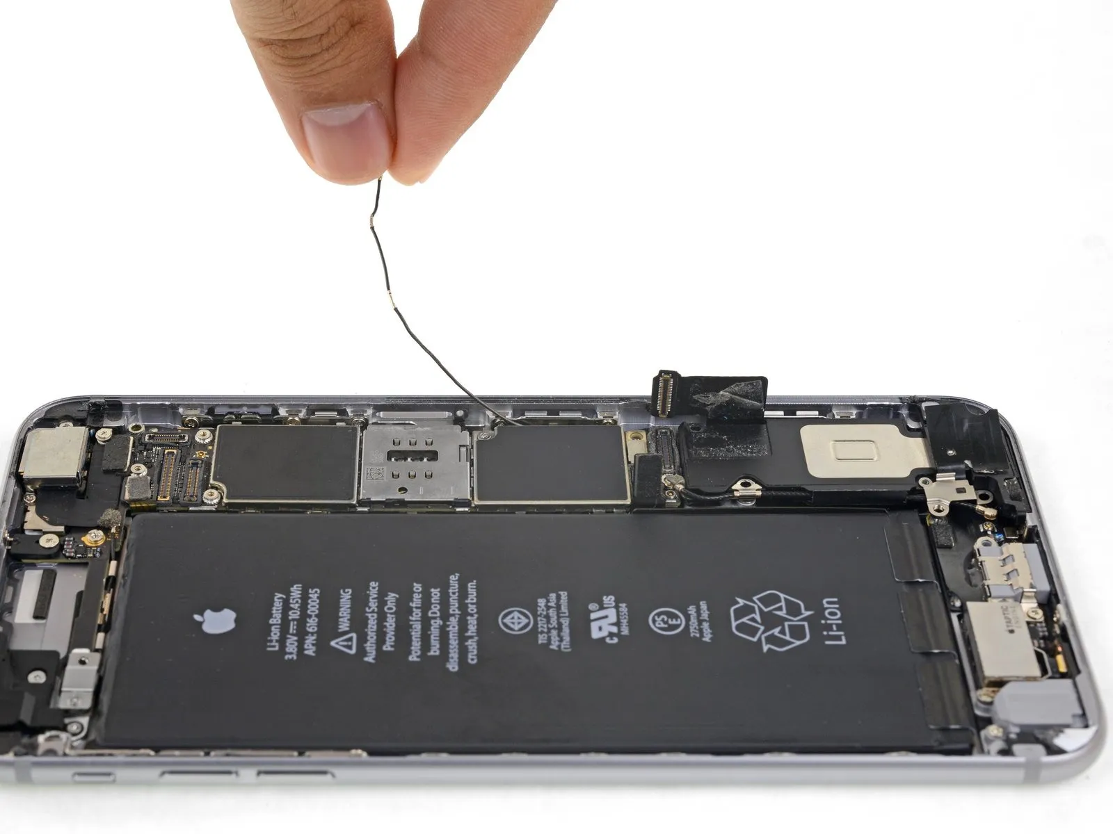

- Gently raise the antenna cable and reposition it away from the phone's perimeter; a spudger can be utilized to aid in separating the cable from the securing clips.
- Should the cable lack sufficient clearance for upward movement, relax the Phillips screw that holds the logic board in place, allowing for increased flexibility of the board. Ensure this screw is properly tightened again when putting everything back together.
- Should the cable become entangled close to the SIM reader, it is probably being held by the SIM tray release mechanism. Employ the tip of a spudger to move the plastic rod aside.
- When reassembling, ensure the antenna cable is positioned beneath the corner of the logic board.
- As part of the reassembly process, the SIM card tray can be re-inserted following the antenna cable's repositioning.
- If you encounter any opposition, pause your work and verify that the SIM tray is not obstructing the antenna cable.
Step 33

- To detach the speaker, first, eliminate the six Phillips head screws that hold it in place on the rear case.
A single screw with a 2.5-millimeter thread diameter is required.
Utilize two screws, each possessing a 2.7-millimeter thread diameter.
A single screw with a 1.5-millimeter thread diameter is also needed.
Additionally, procure one screw exhibiting a 1.7-millimeter thread diameter.
A single 2.6-millimeter screw is responsible for fastening the speaker to the lower edge of the rear case.
Step 34


- Employing a spudger's flat tip, carefully wedge it into the space located along the speaker module's lengthy side and the phone's casing.
Apply slight, controlled pressure to disengage the speaker module. - After the module has become detached, elevate it and extract both the speaker module and the affixed antenna cable from the device.
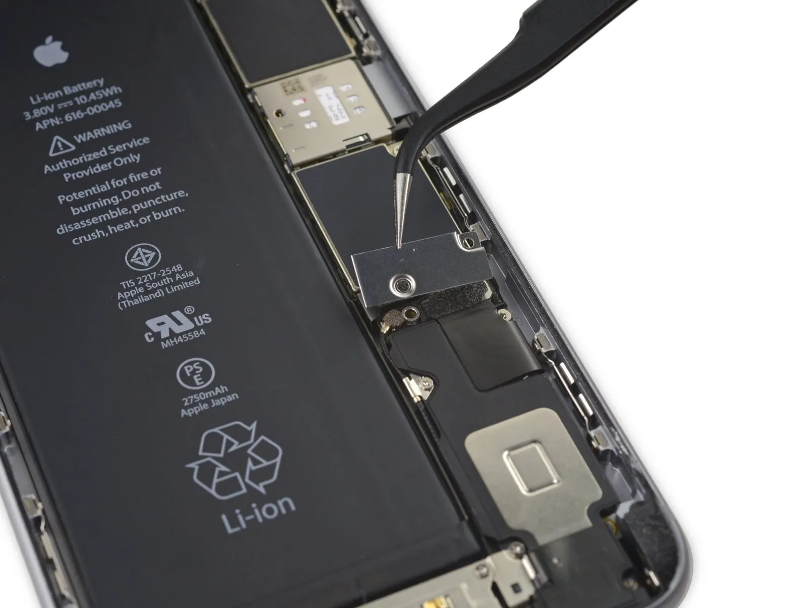
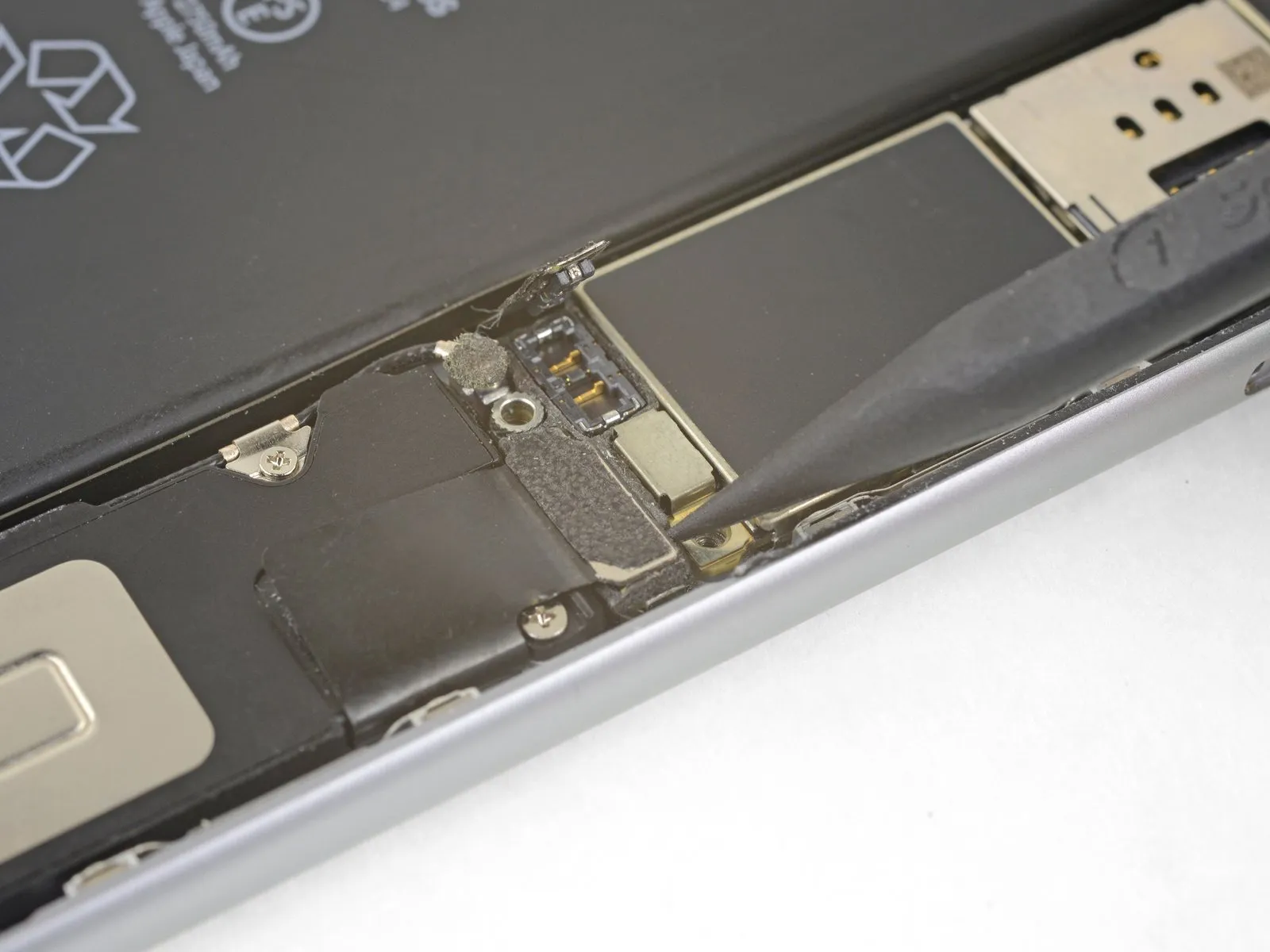
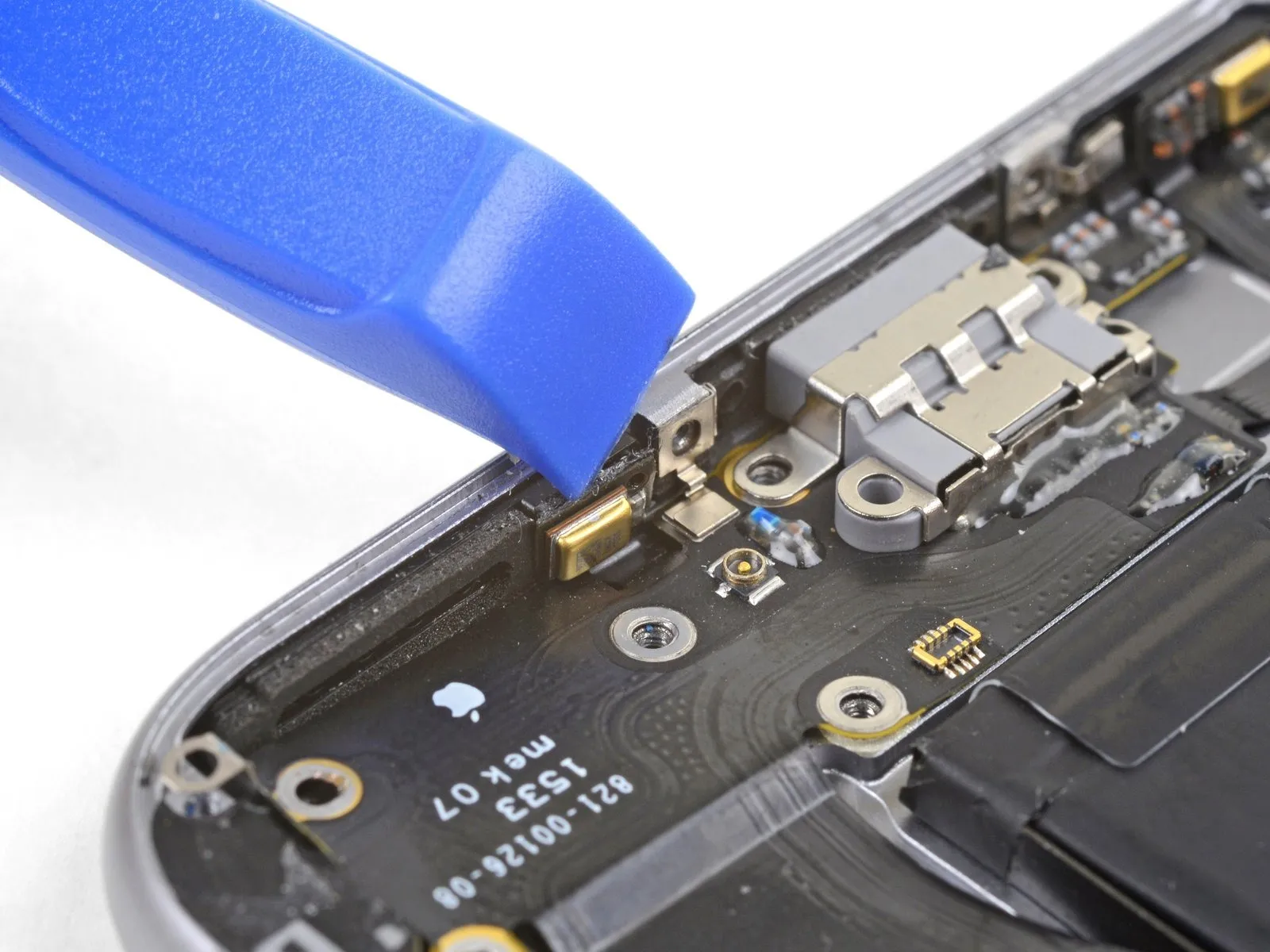
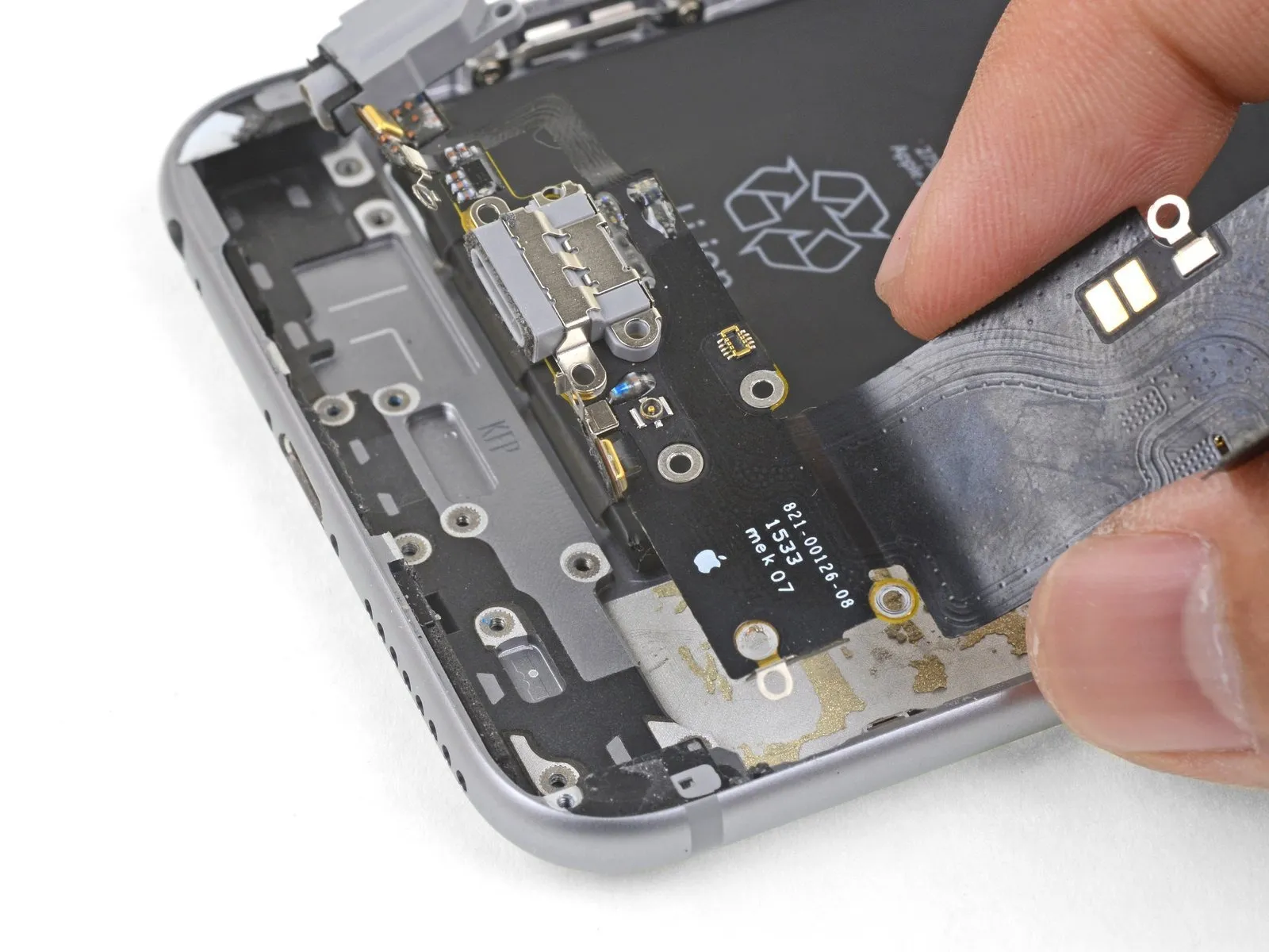
Step 35 | Lightning Connector and Headphone Jack

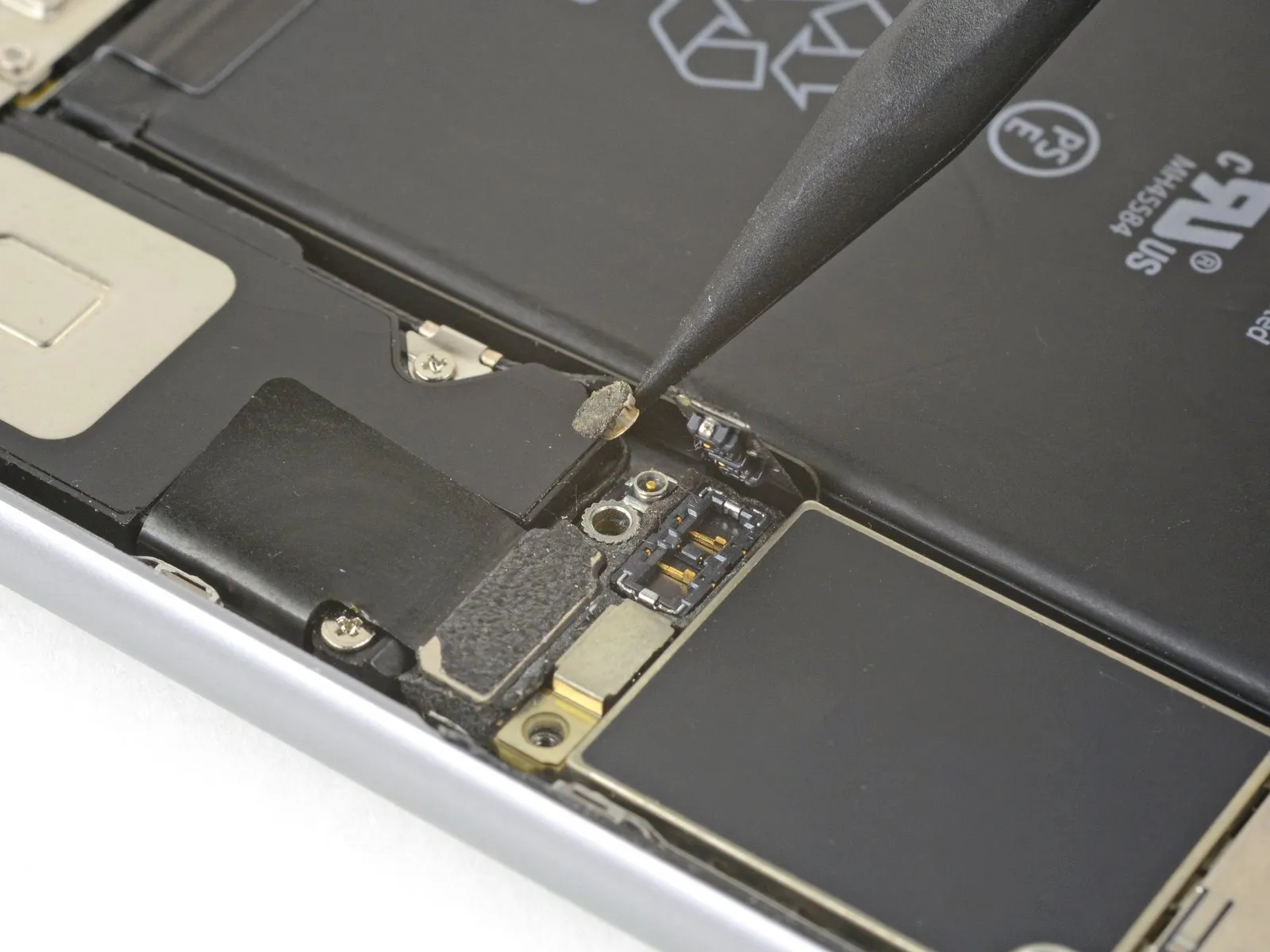
Carefully leverage the tip of a spudger to separate the Taptic Engine flex cable connector from the lower flex cable assembly.
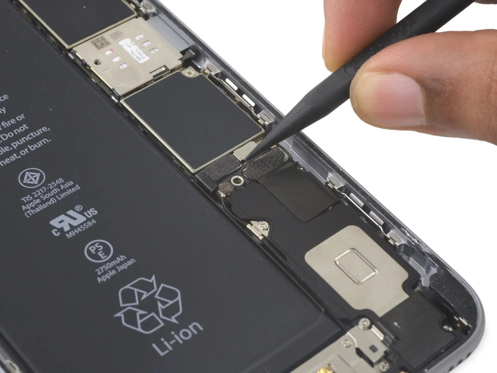
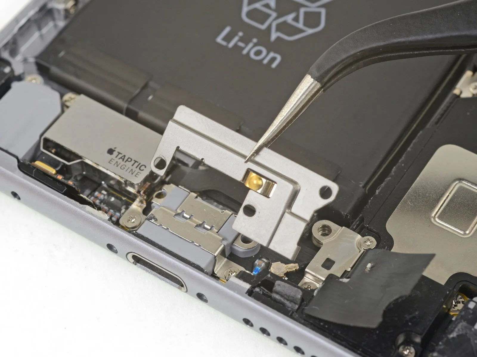
Step 36

- To detach the Taptic Engine, first, eliminate the pair of Phillips head screws that hold it in place on the rear case.
A single screw, measuring 3.1 millimeters in length, is present.
Additionally, a screw with a length of 2.1 millimeters is also utilized. - Following screw removal, proceed with the extraction of the Taptic Engine itself.
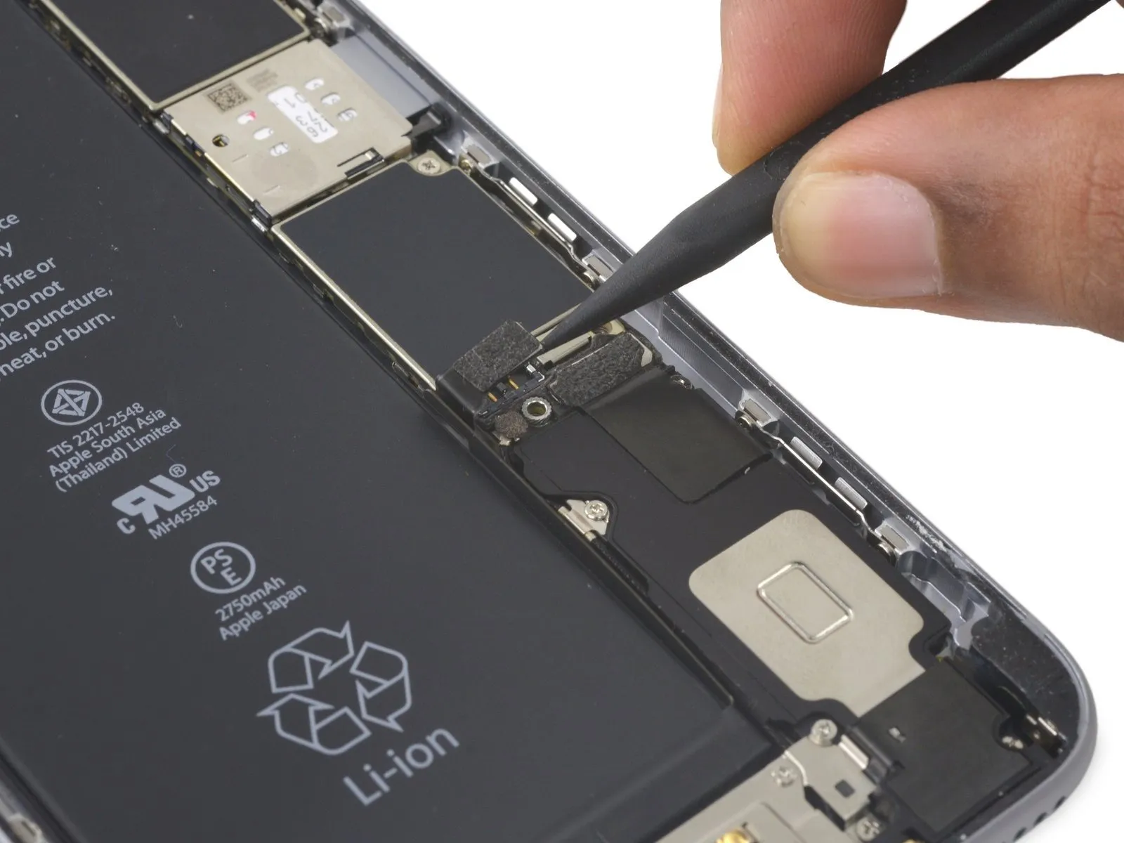
Step 37

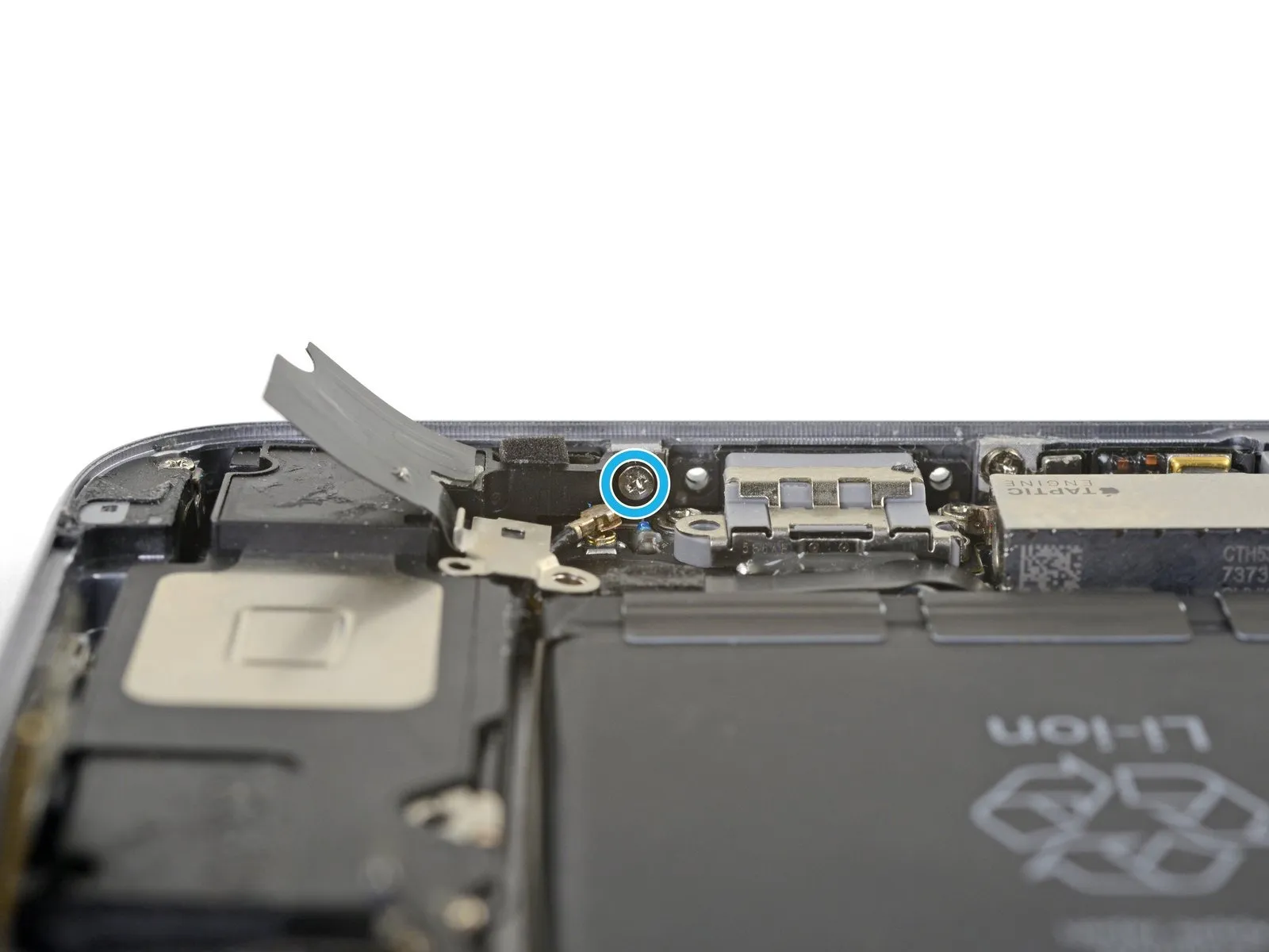
- Carefully lift the adhesive strip covering the screw that fastens the Lightning connector flex cable to the phone's edge.
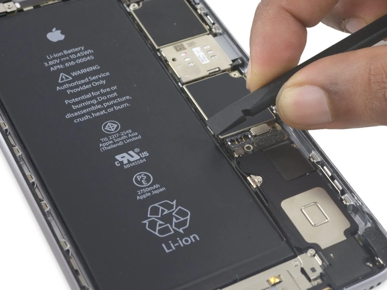
Step 38

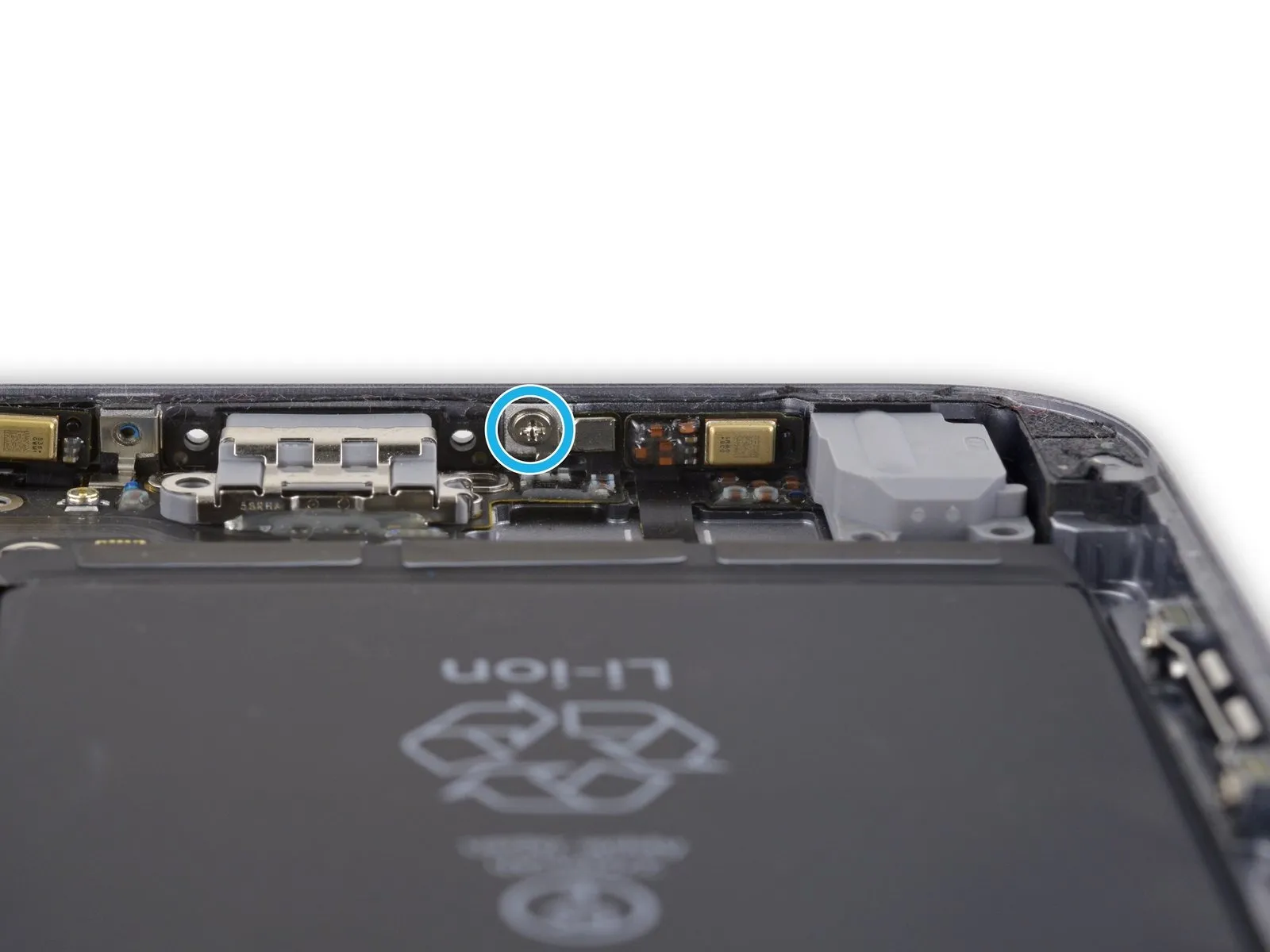
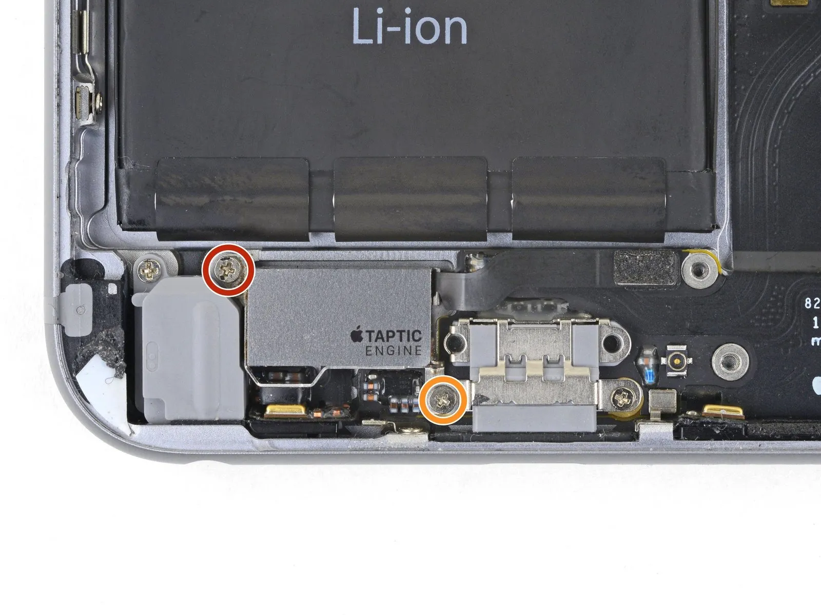
- To proceed, detach the subsequent five Phillips head fasteners:
A single 2.9-millimeter fastener
A single 1.9-millimeter fastener
A single 1.5-millimeter fastener
A single 1.6-millimeter fastener
A single 1.3-millimeter fastener assembly located on the lower border of the rear case.
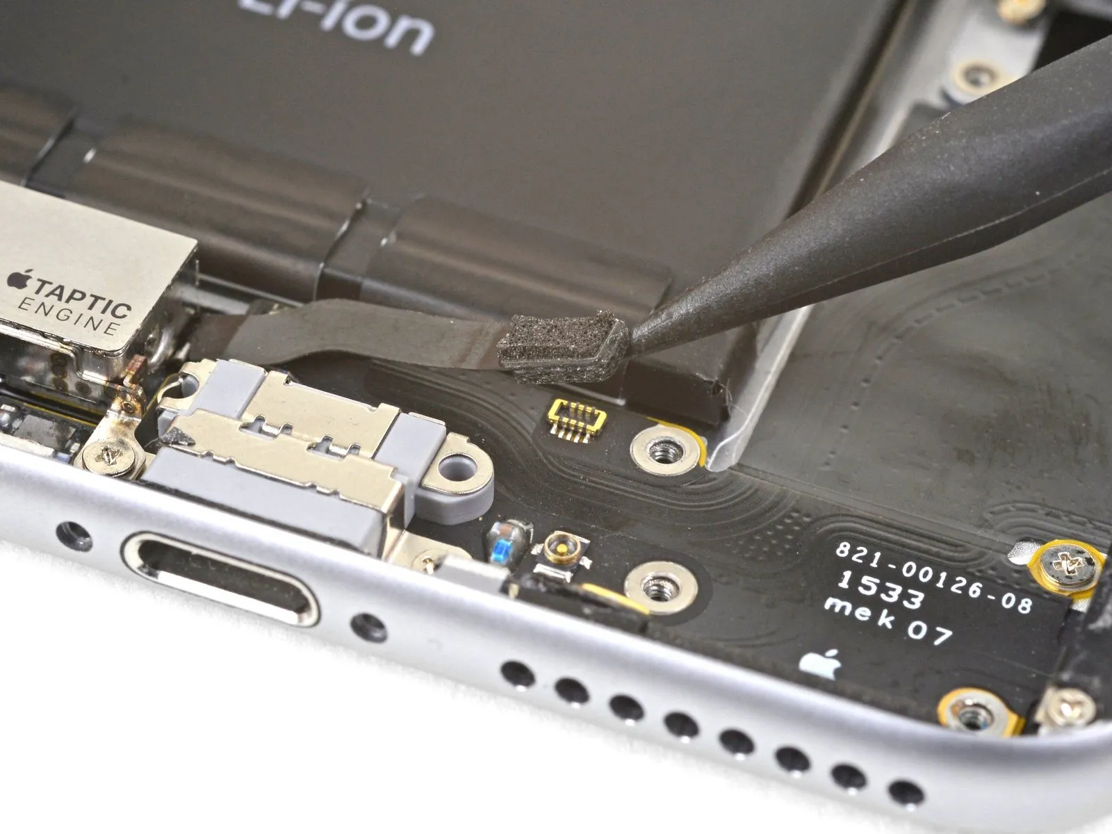
Step 39
- Utilize an iOpener, positioning it along the lower edge of the device to reduce the adhesive bond securing the Lightning connector flex cable.
Allow approximately sixty seconds for the adhesive to become pliable, then lift the iOpener and proceed with the subsequent steps.
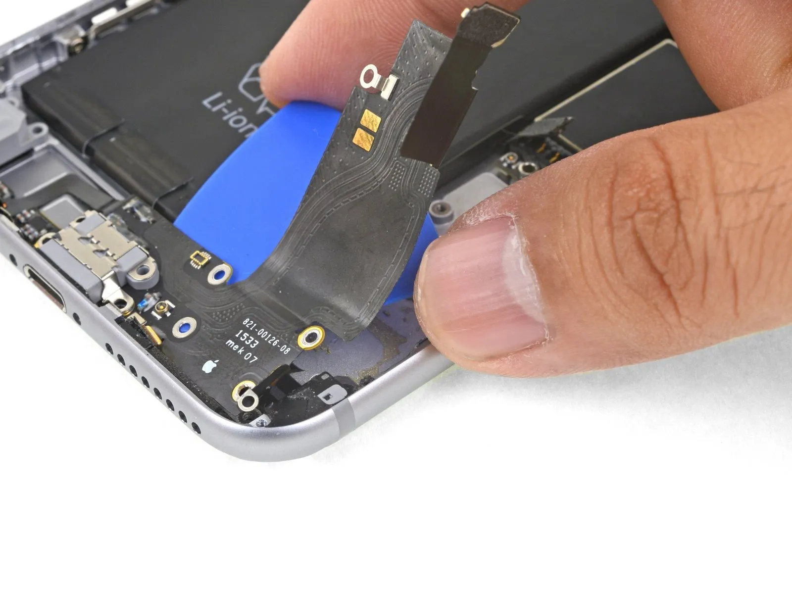
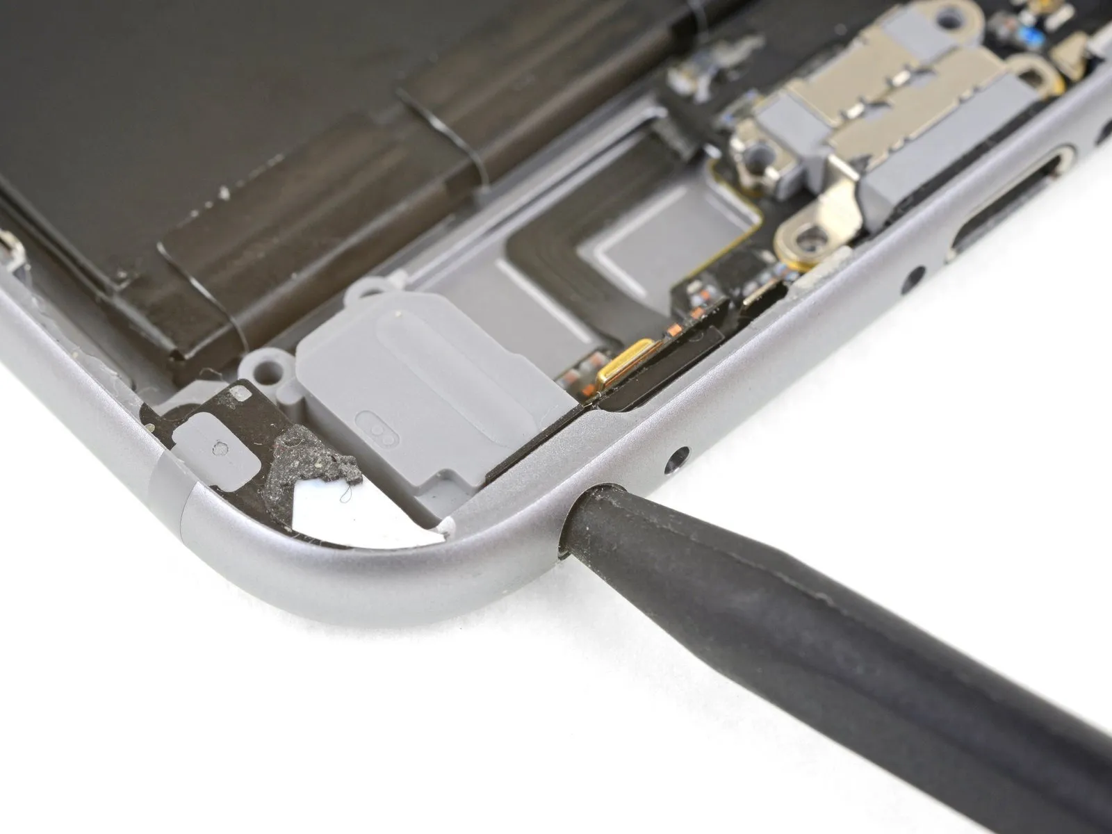
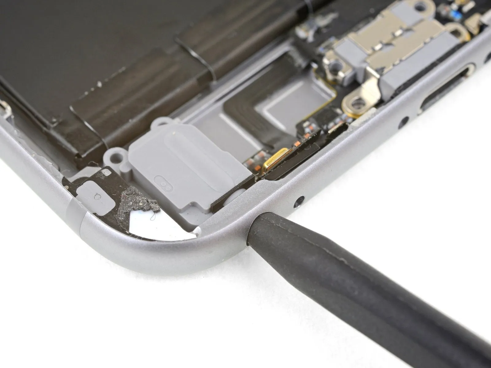
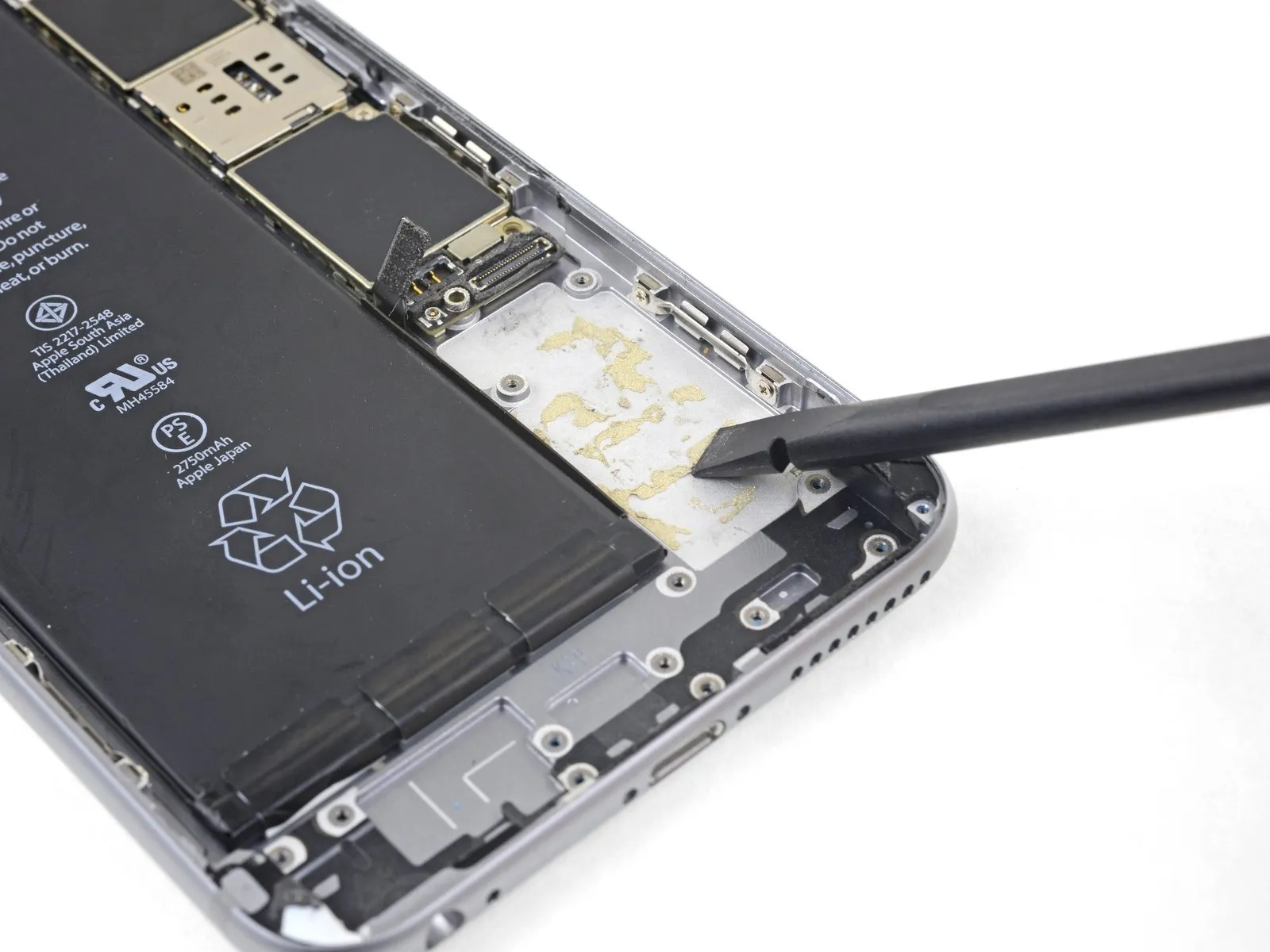
Step 40


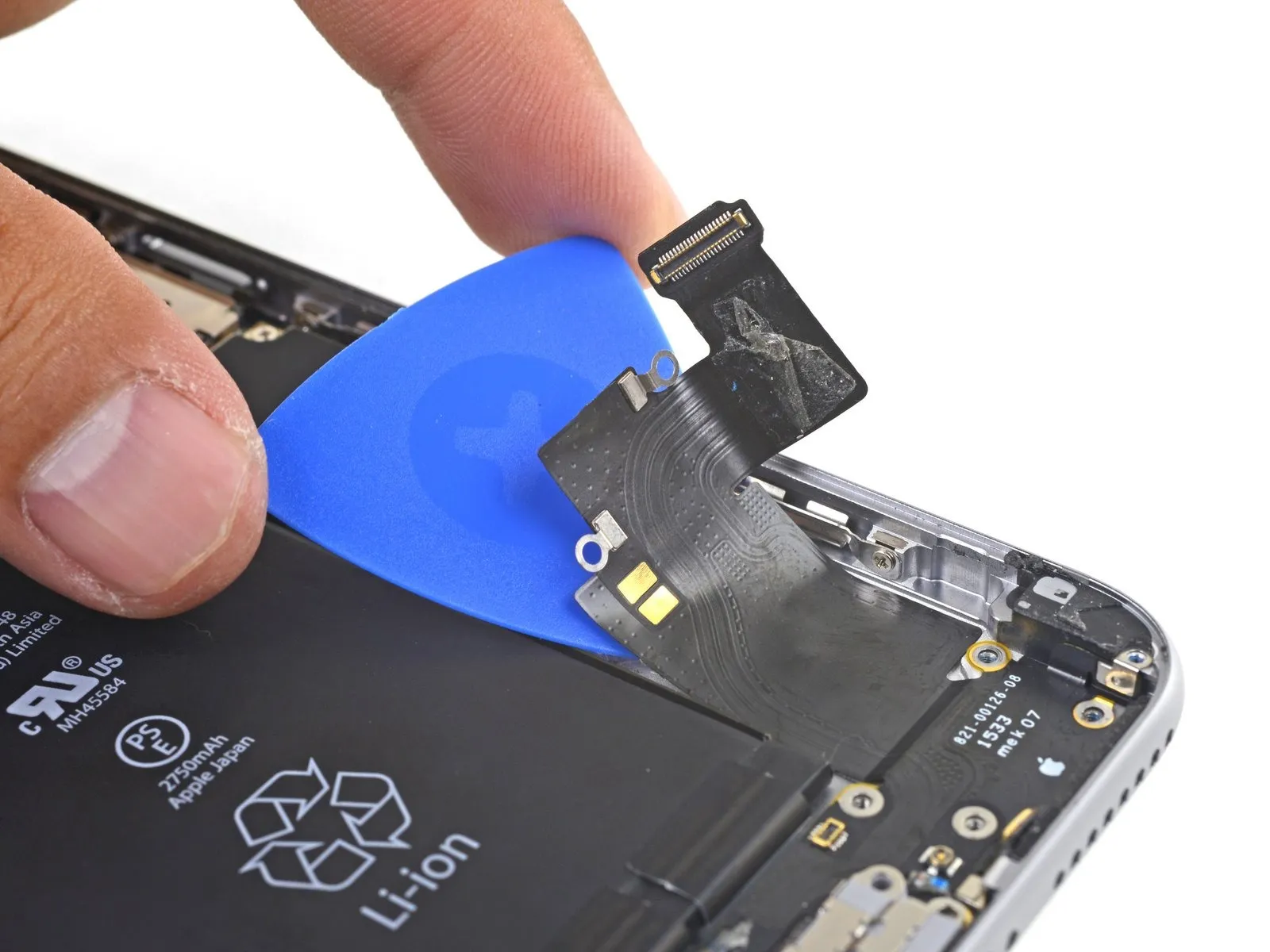
- Carefully slide a separating tool beneath the Lightning connector flex cable, then gently sever the adhesive securing the cable to the back cover.
Step 41


Step 42


Step 43
Step 44
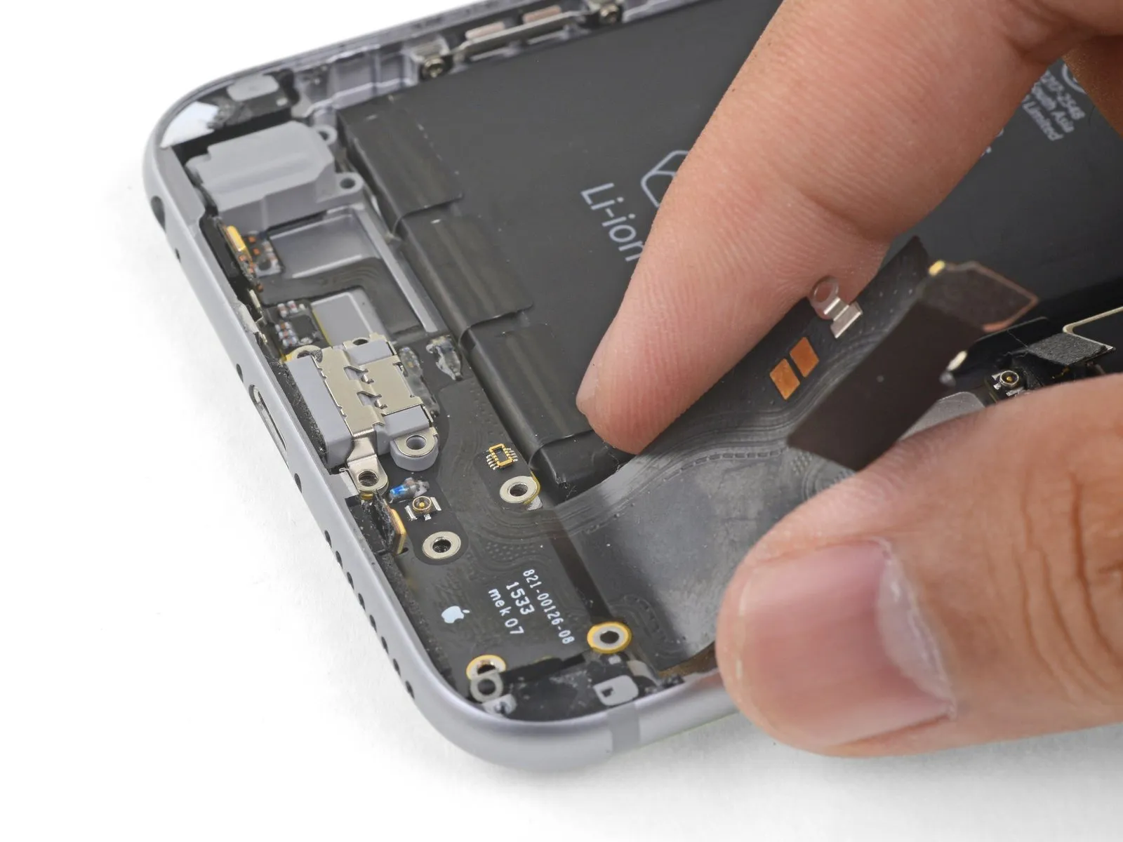
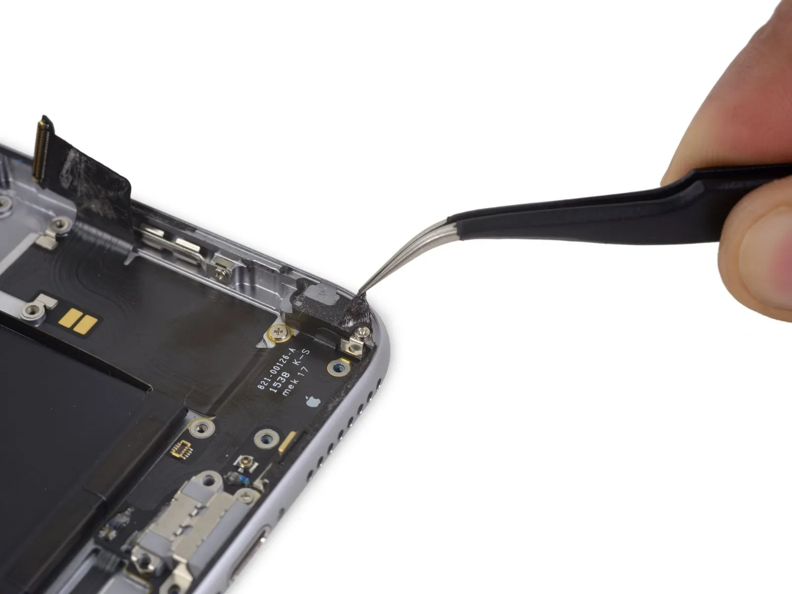
- Detach the Lightning connector assembly.
- Should your new component lack a headphone jack gasket, carefully extract the gasket from the original part with tweezers and affix it to the replacement.
- Prior to reassembly, employ a spudger to thoroughly clean any lingering adhesive from the rear case; utilizing a solvent with a high isopropyl alcohol concentration can assist in this task.