iPhone 6s Plus Volume Control Cable Replacement
Using the instructions provided, substitute the volume control cable within yourApple iPhone 6s PlusThis document also provides instructions for substituting the audio control cable bracket.
Step 1 | Pentalobe Screws
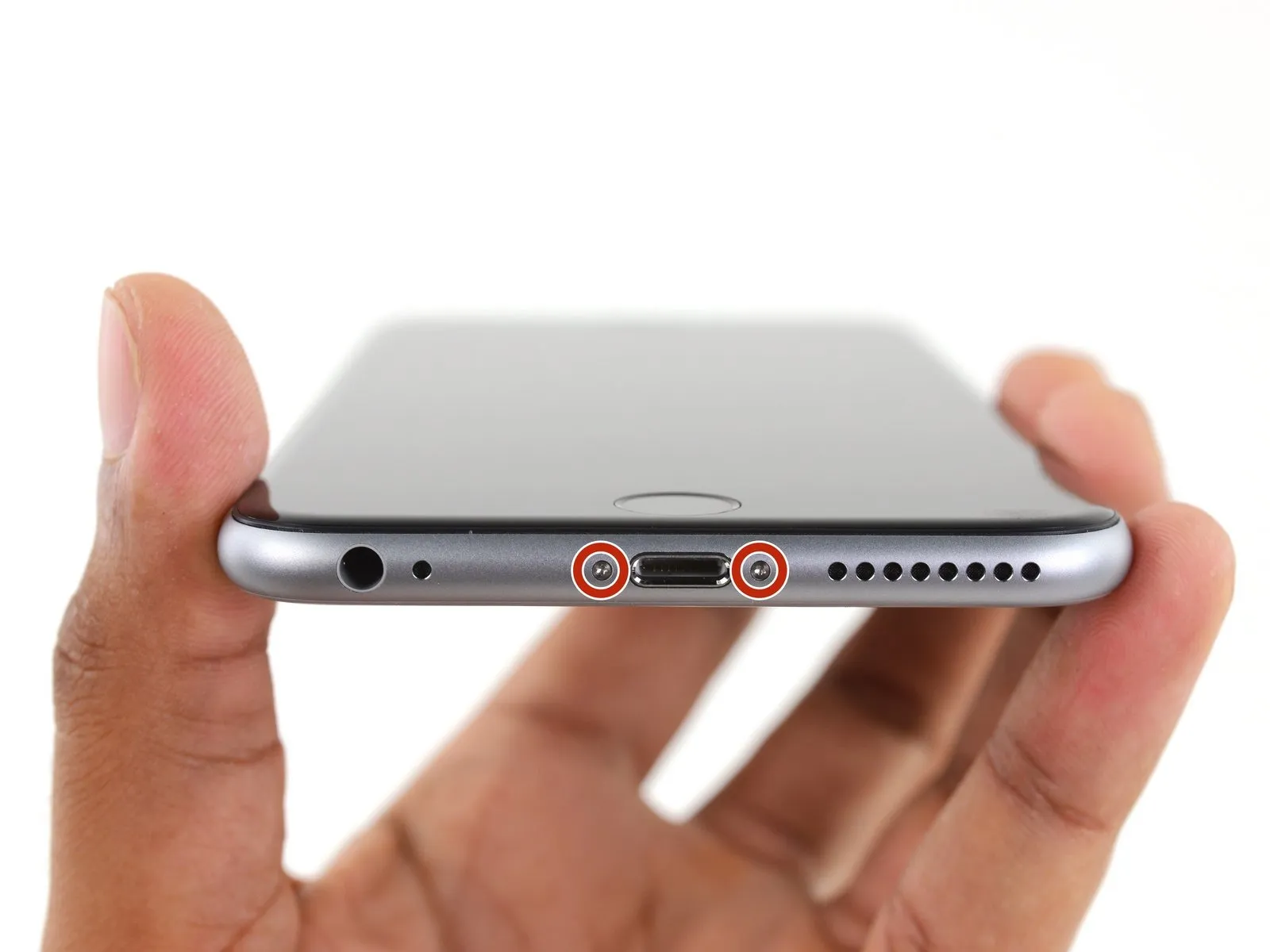
- To prevent fire or explosion hazards from potential puncture damage, ensure the lithium-ion battery's charge level remains below 25% before proceeding.
- To prevent electrical shock or damage to components, ensure the iPhone is completely de-energized prior to starting the repair process.
- Using a Pentalobe screwdriver, detach the two screws, each measuring 3.4 mm, located on both sides of the Lightning connector.
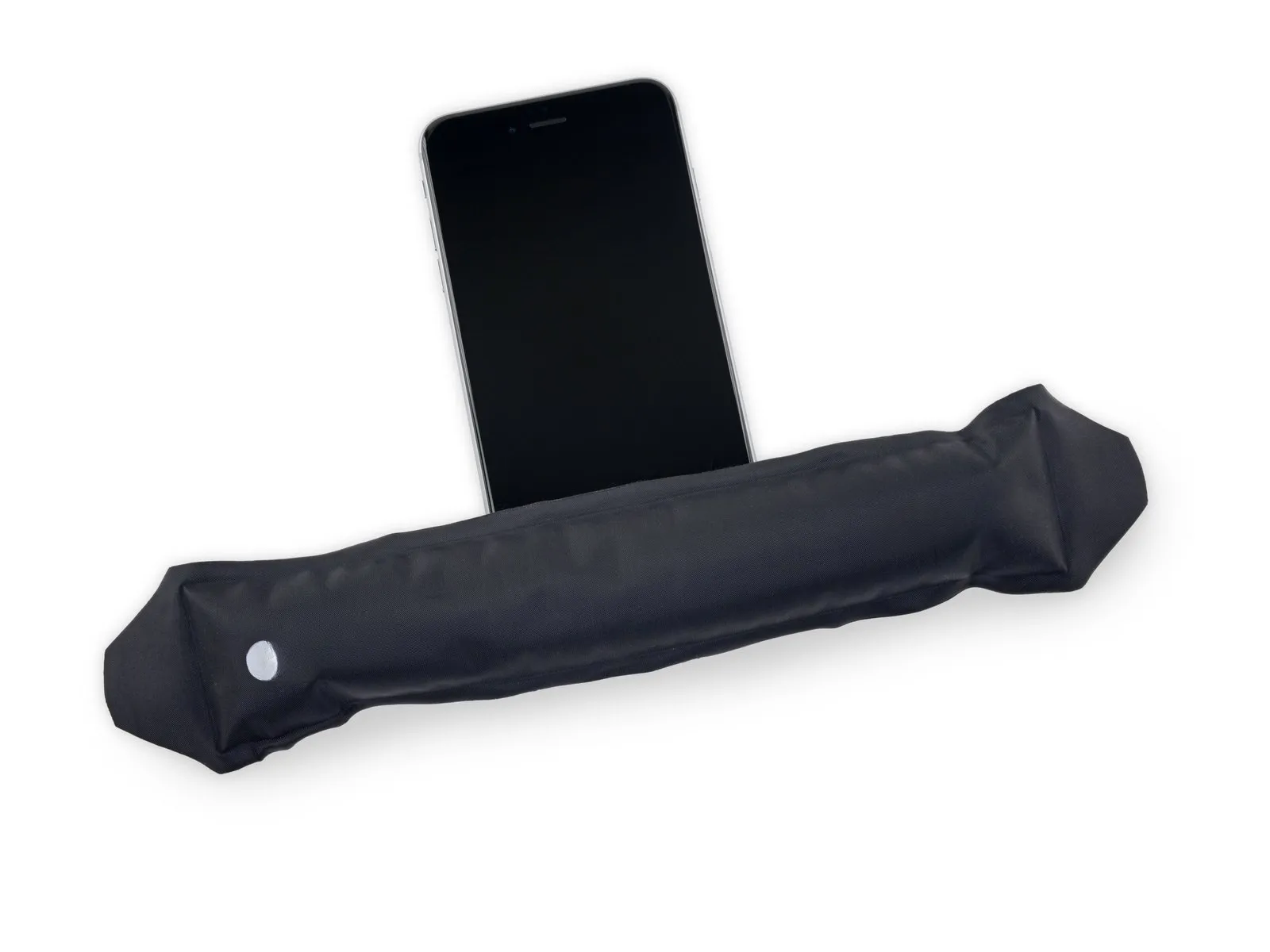
Step 2 | Anti-Clamp instructions


- Forgo the Anti-Clamp procedure and proceed to the instructions three steps further down if you do not have one available.
- Refer to the accompanying guide for detailed procedures regarding Anti-Clamp operation.
- To release the Anti-Clamp's arms, move the blue handle in a rearward direction.
- Position the arms so they extend across the iPhone's left or right side.
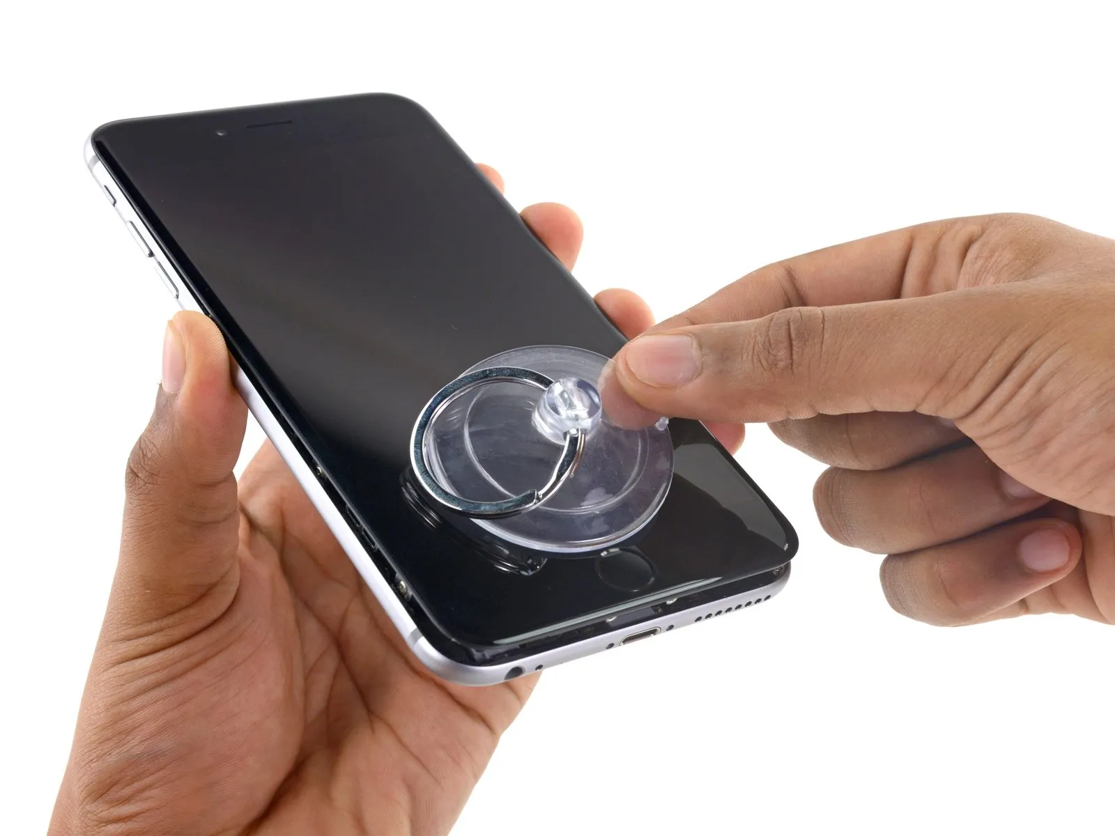
- Secure two suction cups, one to the front surface and one to the rear surface of the iPhone, placing them close to the lower edge, directly above the home button.
- Apply vacuum by pressing the cups firmly against the surface you intend to work on.
- To improve the Anti-Clamp's grip if the iPhone's exterior feels excessively smooth, apply adhesive tape to the device's surface.
Step 3


- Rotate the handle fully, completing a 360-degree turn, observing for the initial expansion of the cups.
- Maintain parallel positioning of the suction cups; should misalignment occur, gently release the suction cups' grip and reposition the arms.
Step 4 | Opening Procedure
- Using a hair dryer or iOpener, gently warm the bottom edge of the iPhone's casing with moderate heat for approximately 60 seconds.
- Applying heat will loosen the adhesive that holds the display in place, simplifying the opening process.
Step 5
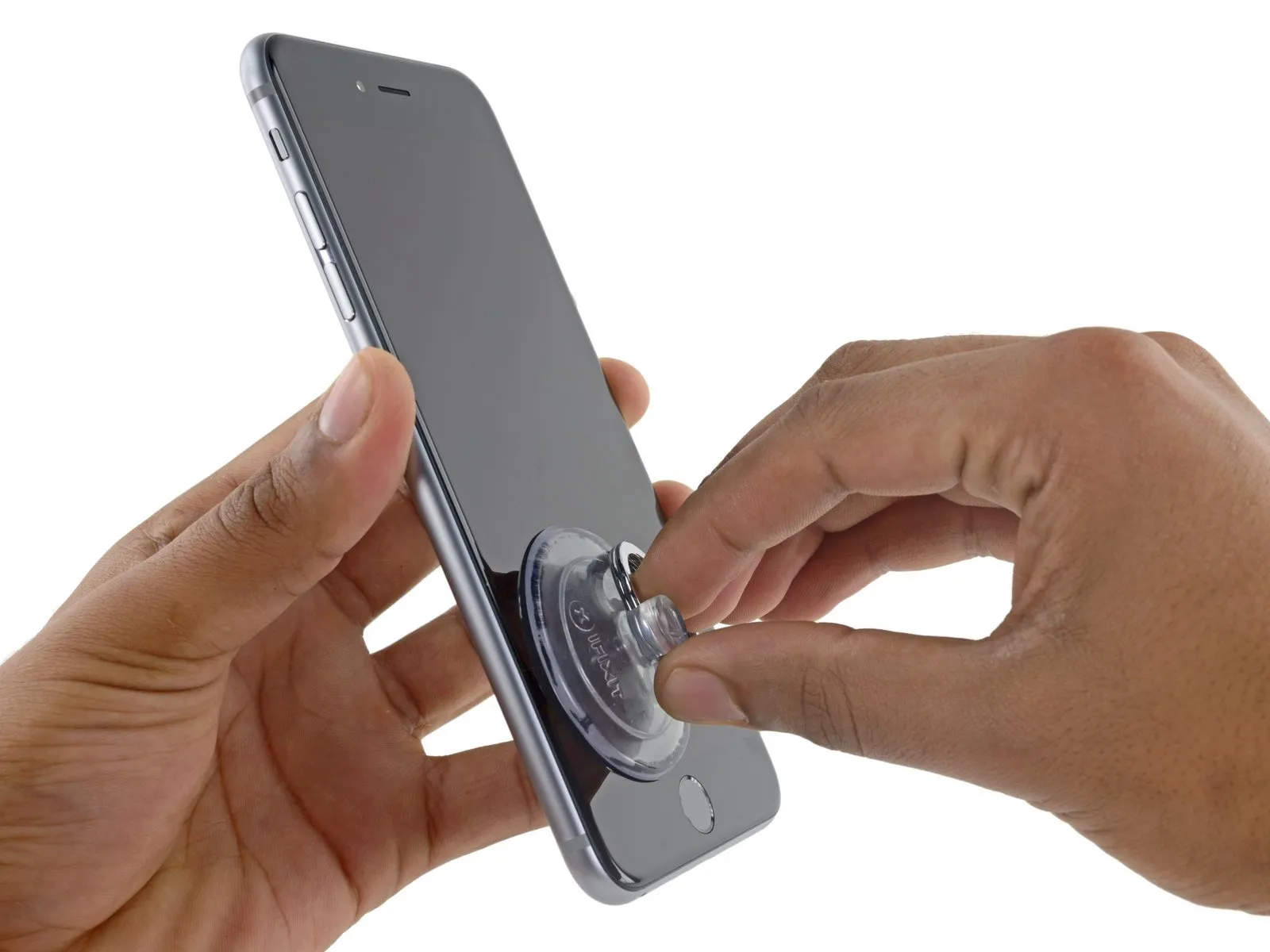
- New adhesive strips should be on hand if you choose to substitute them, as the repair can be finished without replacement and any functional change is unlikely.
To facilitate suction cup attachment on a severely cracked display, apply a sheet of clear packing tape across the damage; otherwise, a robust adhesive tape can substitute for the suction cup. As a last resort, secure the suction cup directly to the fractured screen using superglue.
Step 6
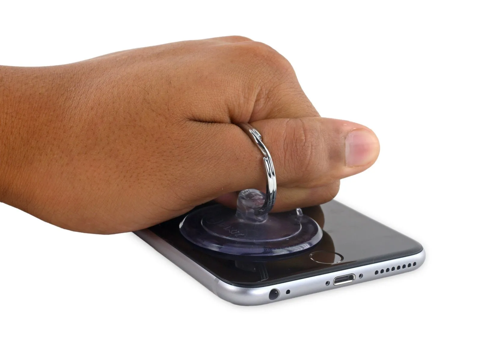
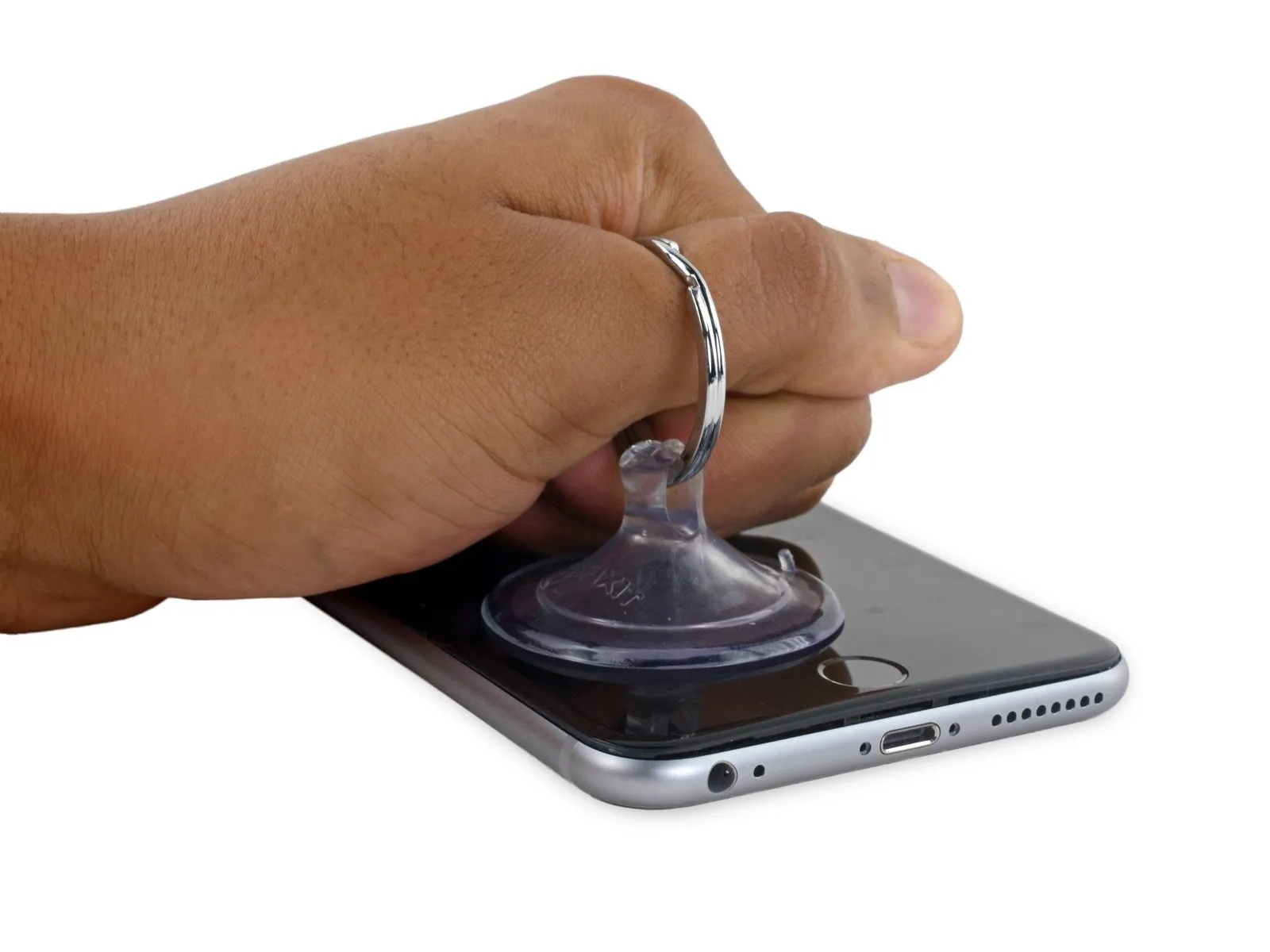
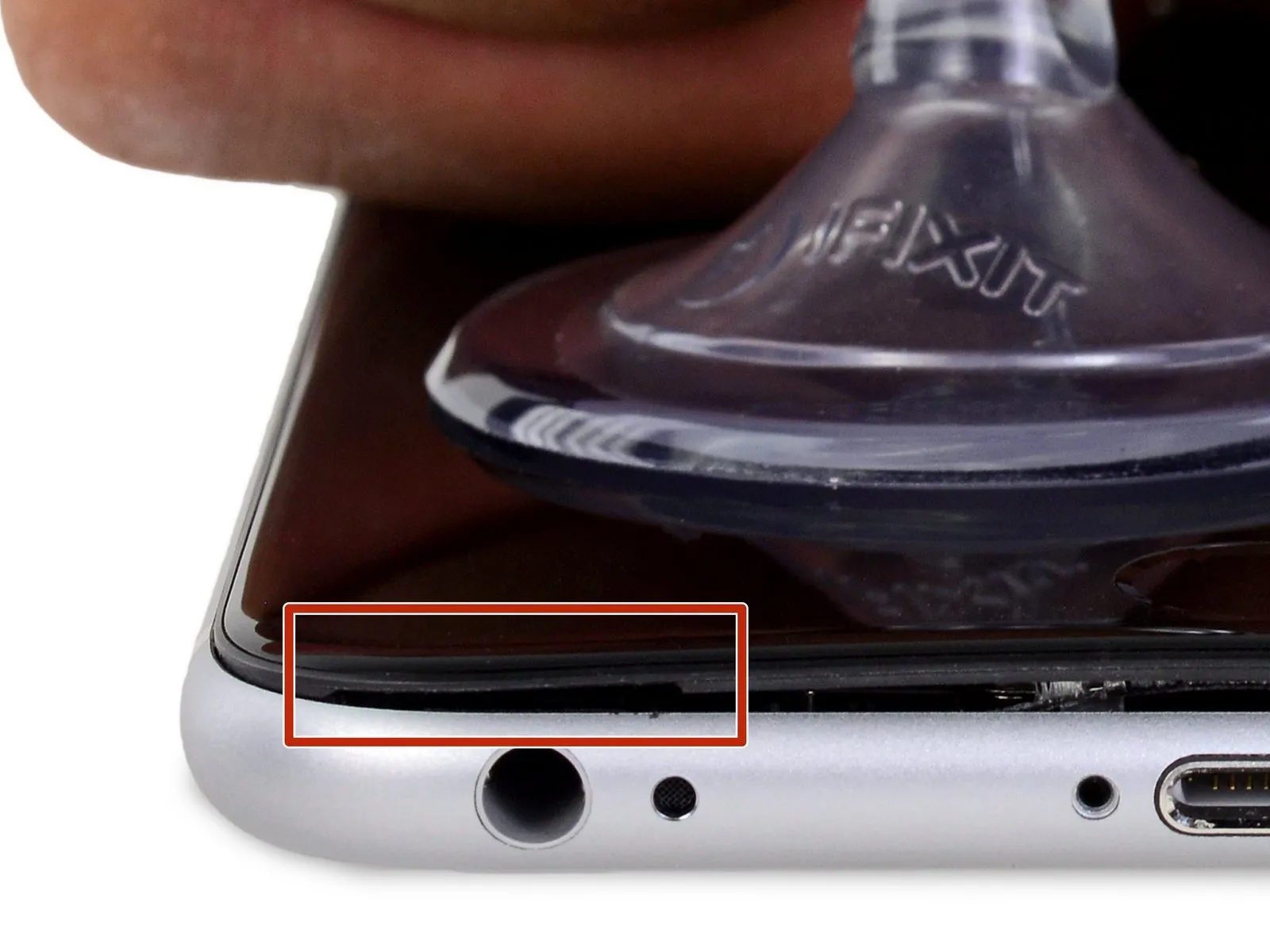
- Apply steady, even force to lift the suction cup, generating a small separation between the front panel and the rear case.
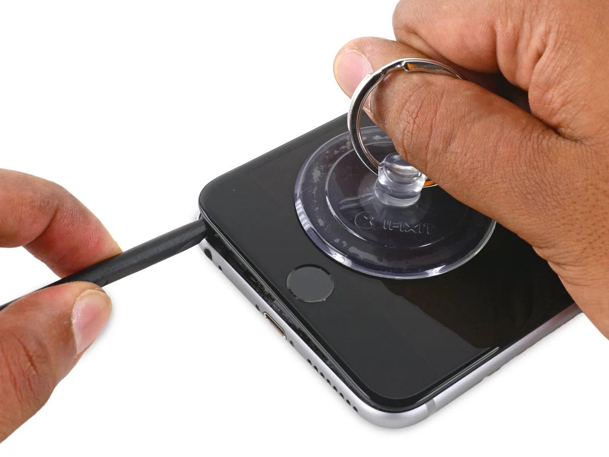
Step 7

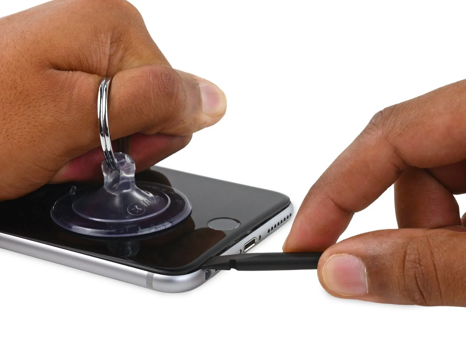
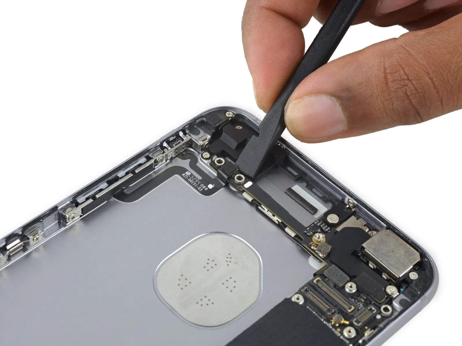
Carefully keeping the suction cup firmly attached, use the spudger's flat tip to access the separation between the housing and the internal components, positioning the tip just over the headphone jack.
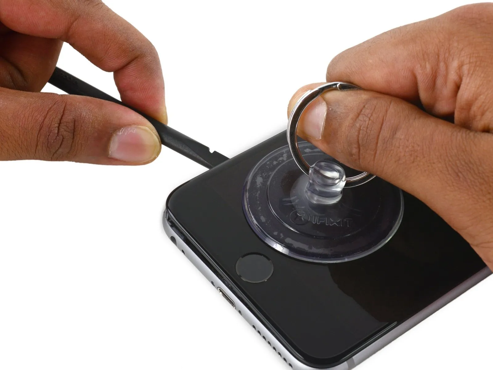
Step 8
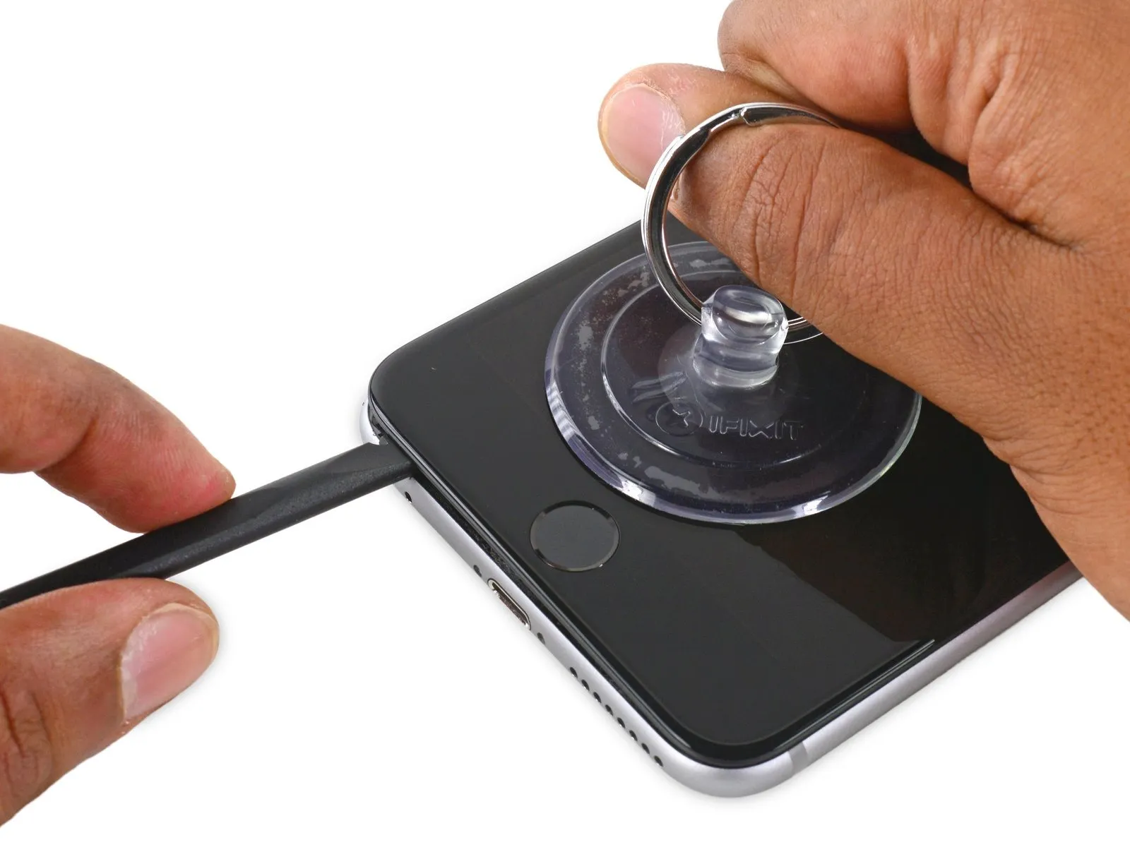
- Using the spudger, gently increase the separation between the front panel and the rear case.
Step 9


Step 10
Step 11


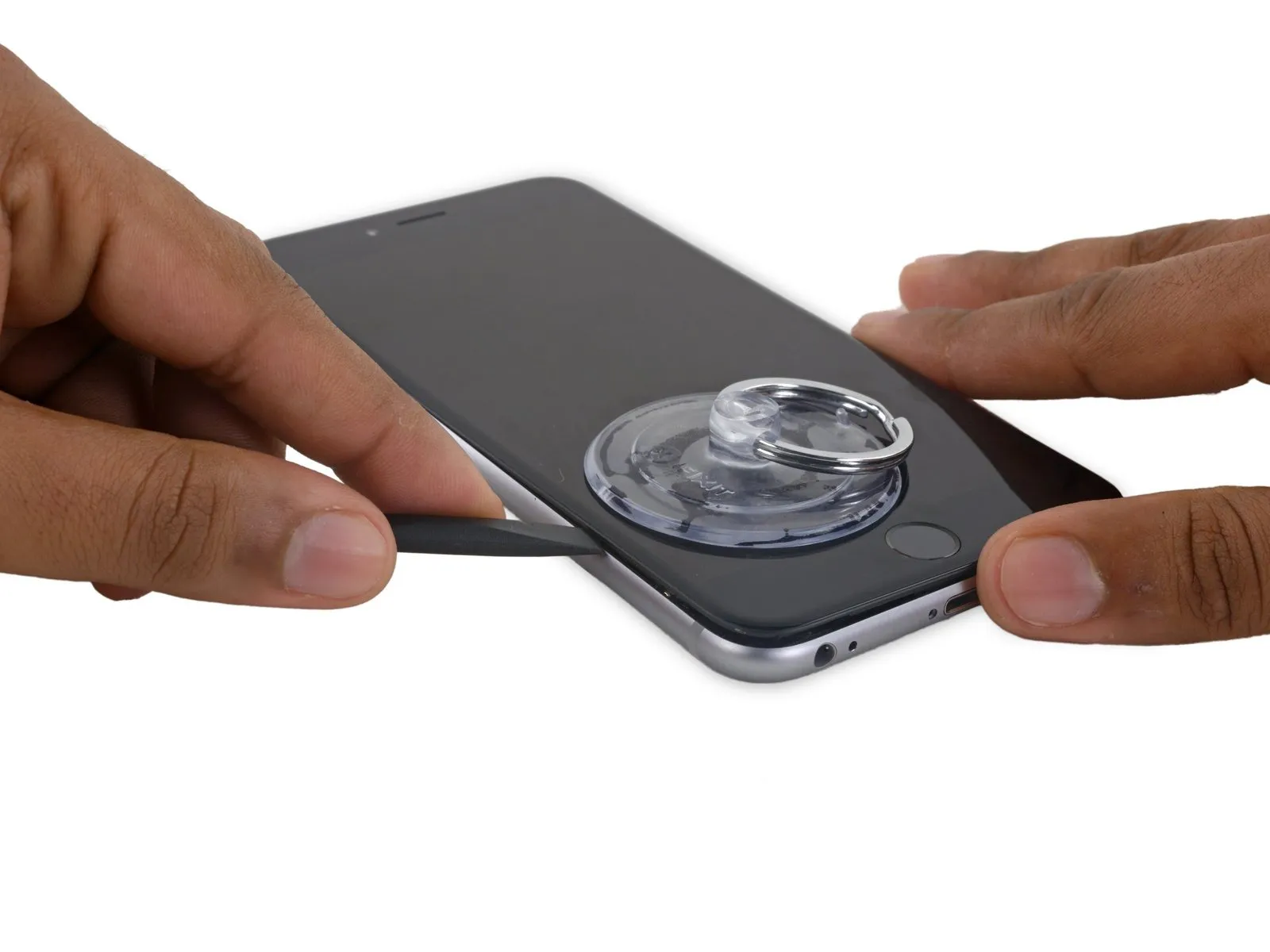
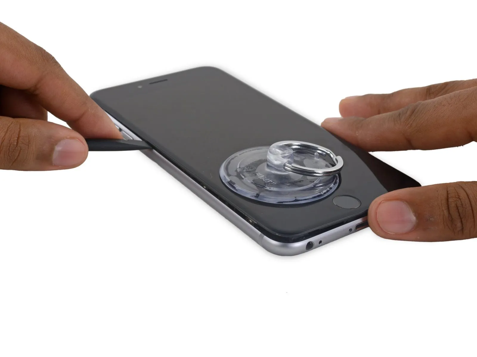
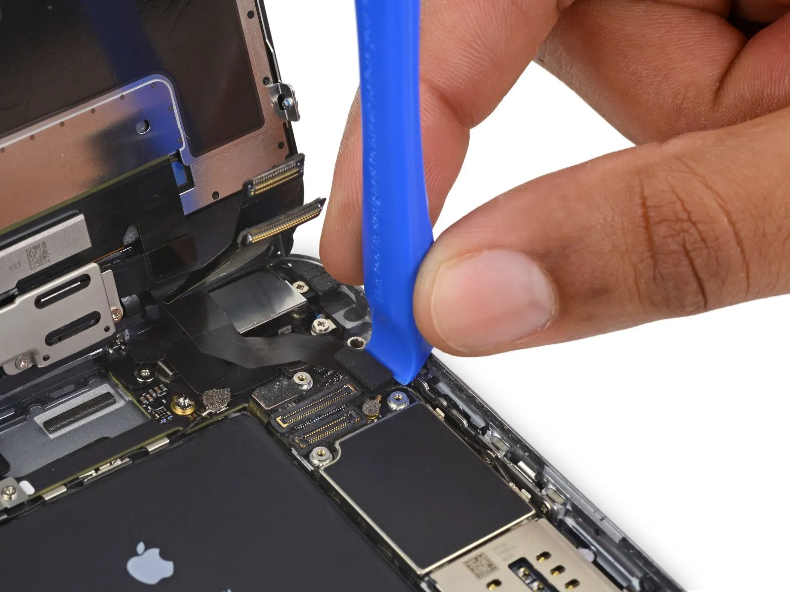
- Using a screwdriver with a flat tip, carefully slide it into the slot.Use a plastic pry tool, often referred to as a spudger.Locate the display's right side.
- Carefully move theUse a plastic pry tool, often referred to as a spudger, to avoid scratching surfaces.Raise the component along the right-hand vertical plane.
Step 12


- Employ a 3/8-inch socket wrench to loosen the retaining bolt, ensuring you maintain a firm grip and wear safety glasses to protect against potential debris; subsequently, carefully detach the component.Use a plastic pry tool.Maintain pressure on the rear case with your fingers while lifting the suction cup to release the phone.
- Carefully detach the display; complete removal risks damaging the data cables located along the iPhone's upper edge.
Step 13

Step 14

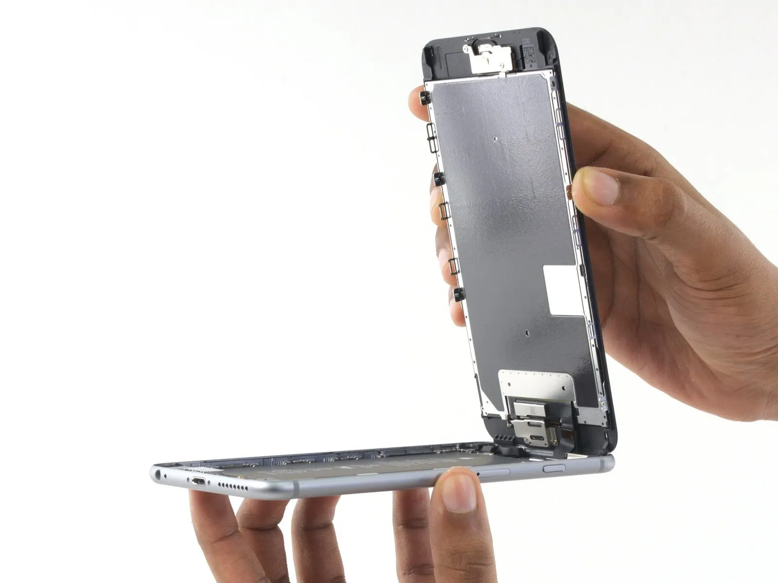

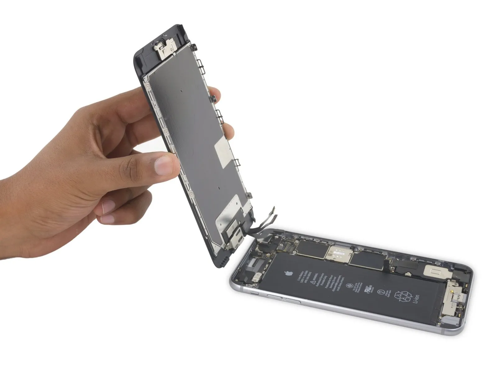
- Employing a careful grip, raise the display assembly, leveraging the front panel's upper clips to act as a pivot point and separate the device.
- Carefully separate the display assembly from the device housing, creating a gap of approximately one millimeter.Ensure the angle is precisely 90 degrees.Position the device at an angle, securing it in place with support to prevent movement during the repair process.
- To prevent damage, limit the display's exposure during the repair process.Rotate to a 90-degree angle.Care must be taken during separation as the display, digitizer, and front camera remain linked to the phone’s upper portion via delicate cables prone to damage.
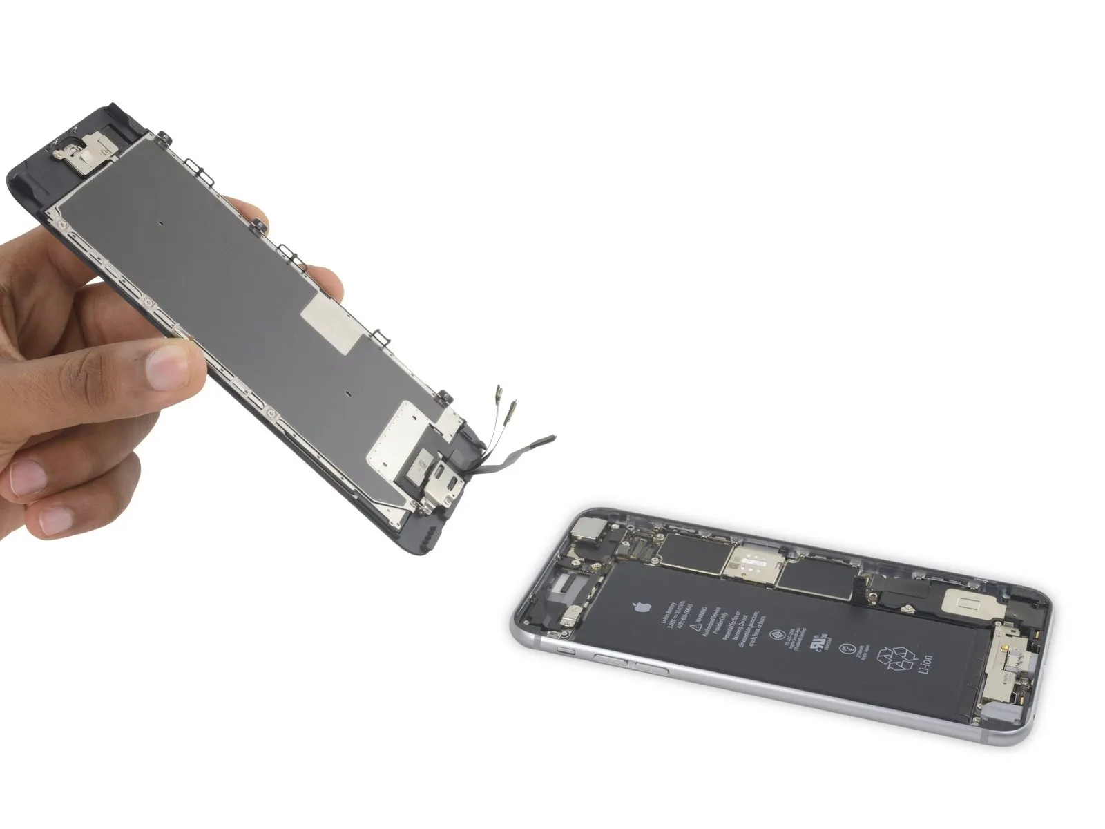
- To avoid stressing the display's wiring during the repair process, secure it with a rubber band.
- As a temporary measure, an unopened, standard-sized canned drink can provide the necessary support for the display.
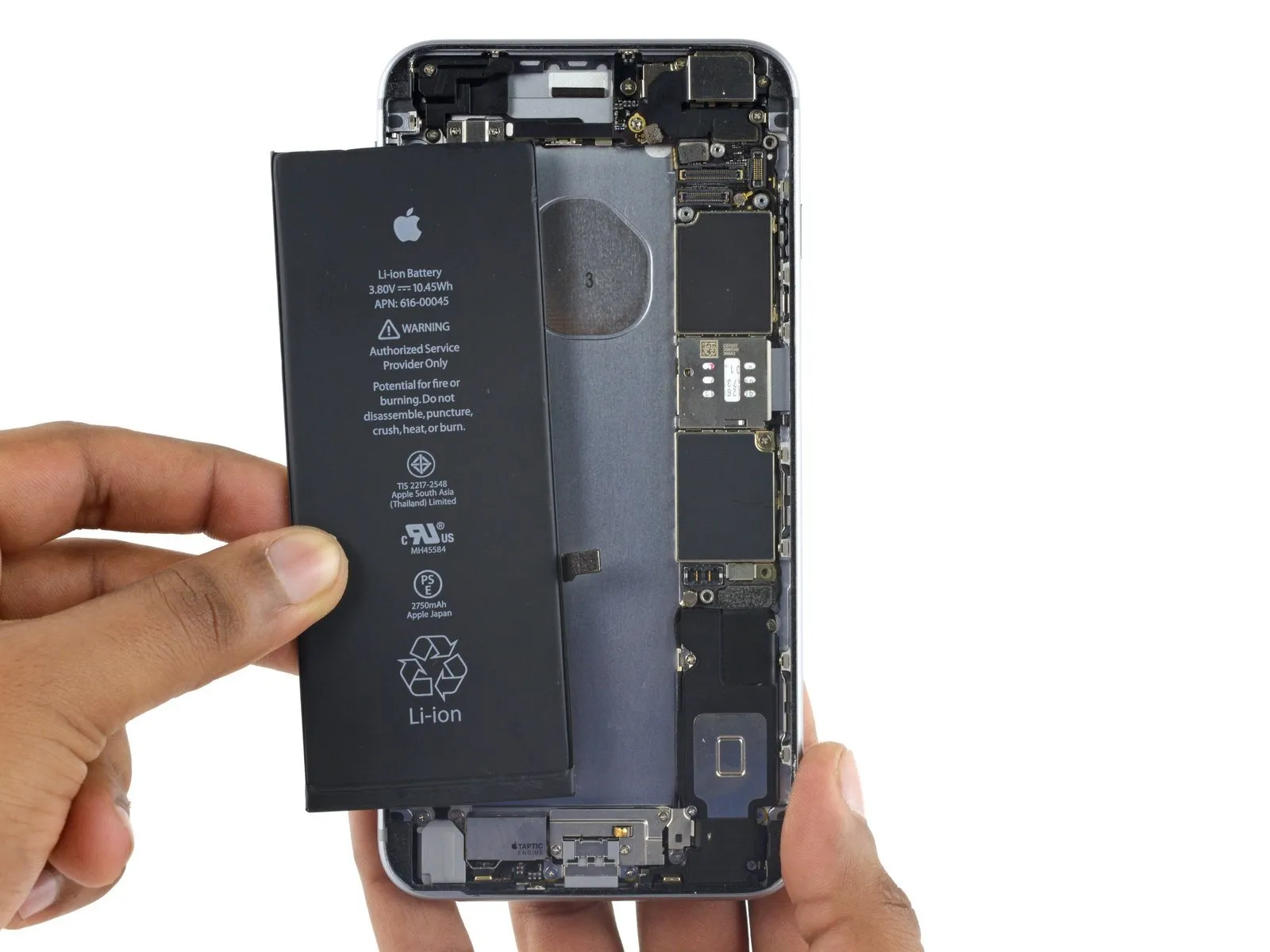
Step 15 | Battery Connector
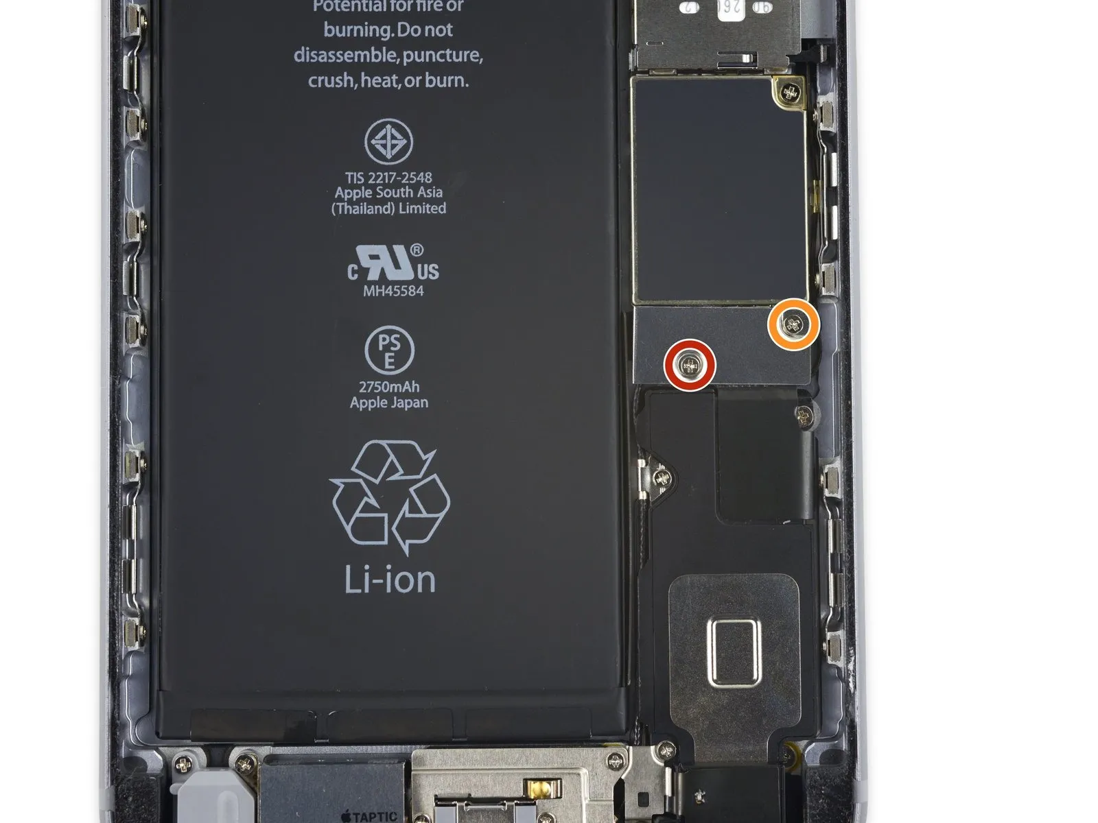
- Detach two.Use a Phillips head screwdriver.Fasten the battery connector bracket to the logic board, ensuring the screws are tightened to the specified lengths.
- Begin the process by performing action one.Use a screw with a diameter of 2.9 millimeters.
- Begin the process by executing the singular action.Use a 2.3-millimeter screw.
To prevent irreversible damage, meticulously organize all screws during disassembly, ensuring they are returned to their original locations during reassembly.
Step 16
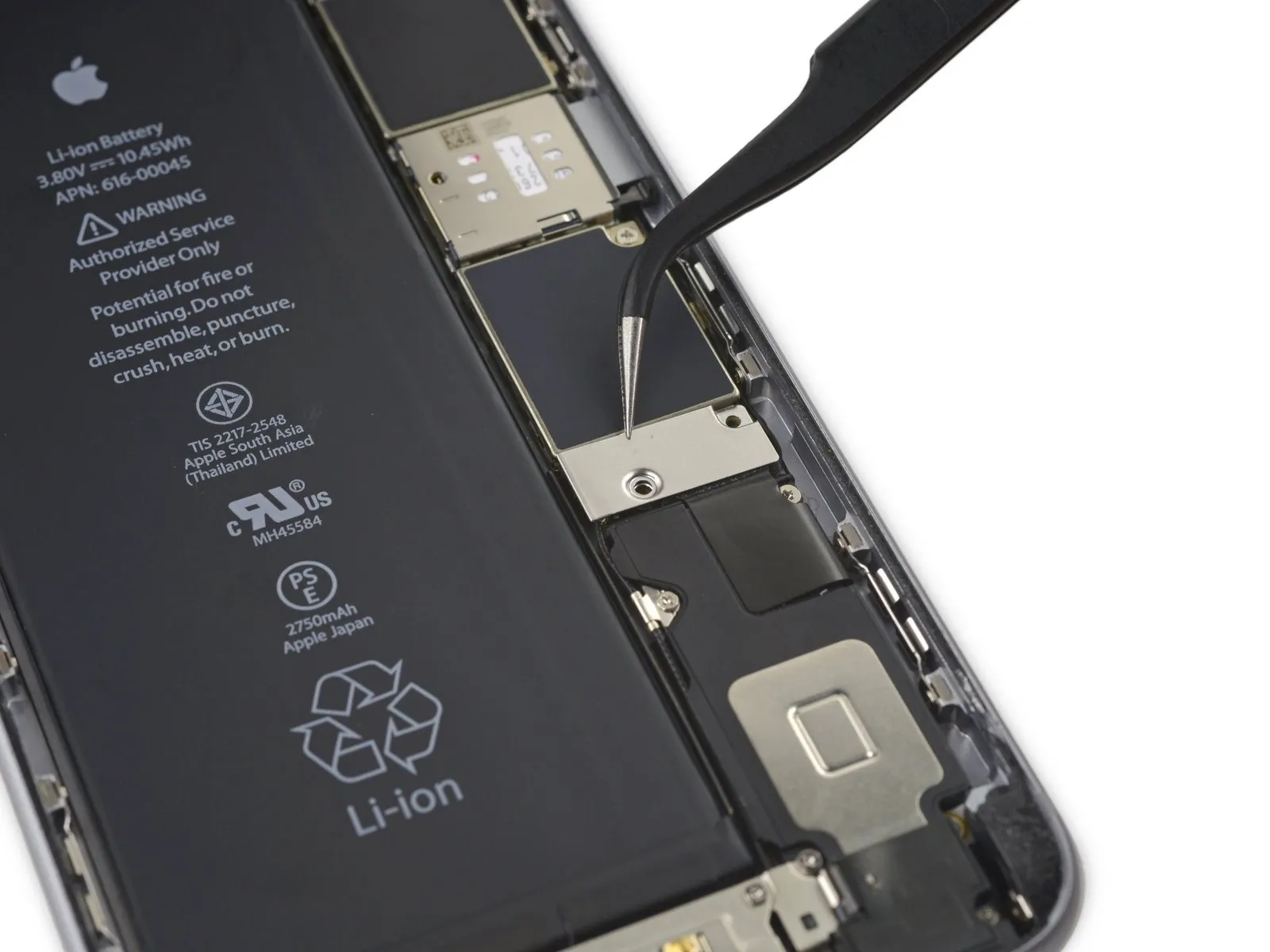
Step 17

Employ a 3/8-inch socket wrench to loosen the retaining bolt, ensuring you maintain a firm grip and avoid excessive force to prevent damage to the threaded insert.Use a plastic pry tool to gently separate.Carefully detach the battery connector from the logic board by applying upward pressure with a clean fingernail or similar tool.
Step 18


To prevent unintended electrical connections, carefully reshape the connector and then activate the iPhone to allow continued operation during the repair process.
Step 19 | Display Assembly
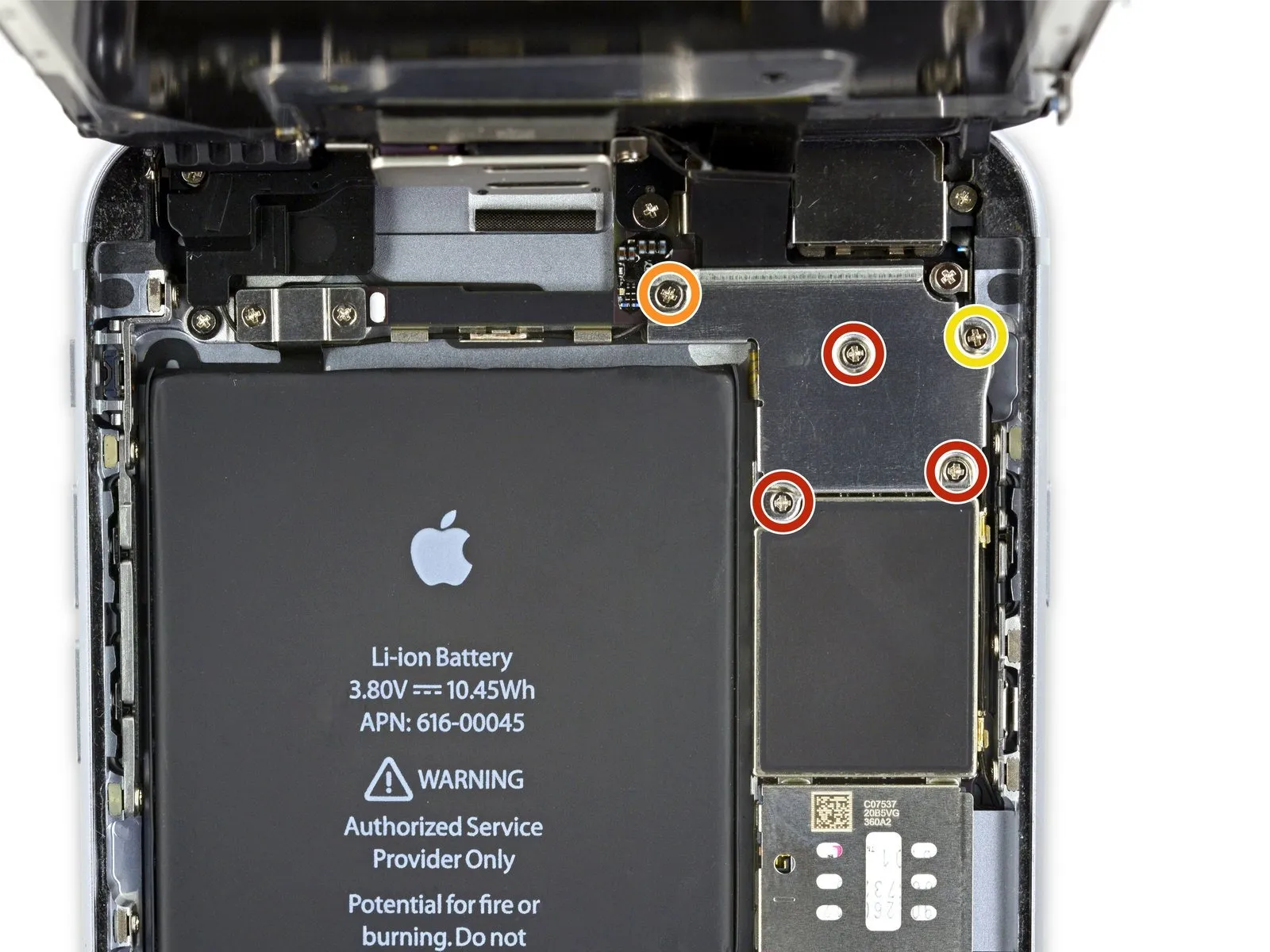
- Detach the listed components.Use a Phillips head screwdriver.:
- Use three screws, each measuring 1.3 millimeters.
- A screw with a diameter of 1.6 millimeters is required.
- A screw with a 3.0 mm diameter is required.
Ensure proper alignment and secure installation of this component during the reassembly process.Use a screw with a diameter of 3.0 millimeters.Ensure the component is positioned precisely in the upper-right quadrant of the bracket to prevent potential logic board damage.
Step 20
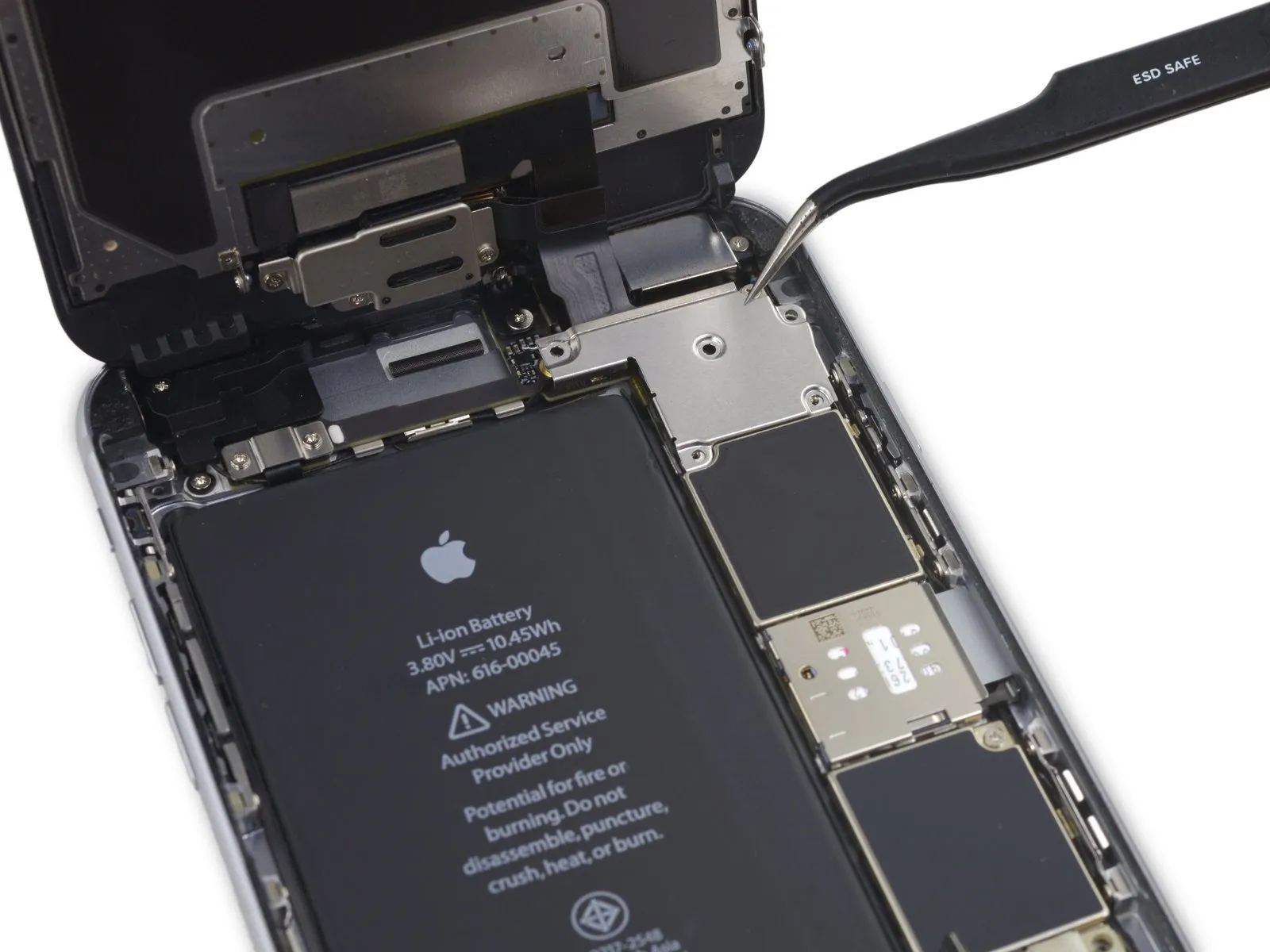

Using a Phillips head screwdriver, detach the bracket securing the display cable.
Step 21

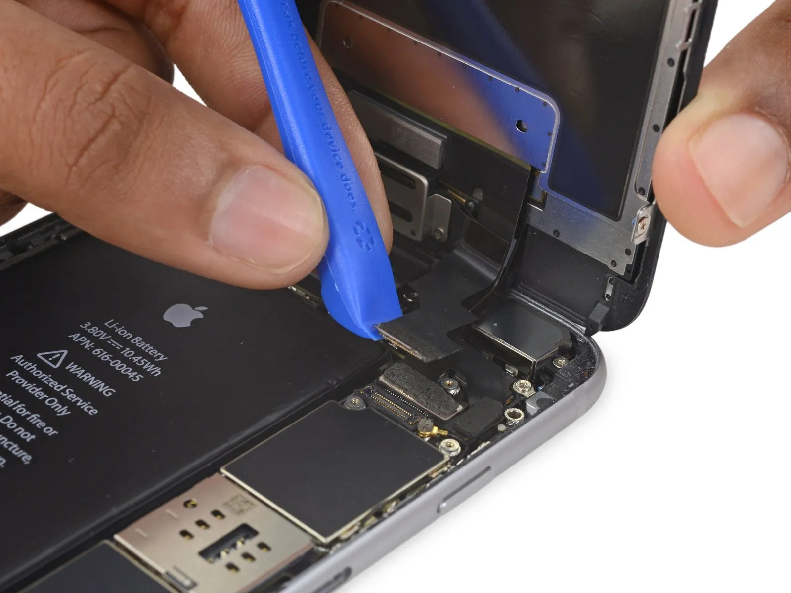
- Avoid applying force to the logic board socket while releasing the connector; focus solely on the connector's release mechanism.
- Employ a 3/8-inch socket wrench to loosen the retaining bolt, ensuring you maintain a firm grip and avoid excessive force to prevent damage to the bolt head or surrounding components; torque the bolt to 18 ft-lbs upon reinstallation, observing all safety precautions outlined in section 4.2 regarding potential pinch points.Use a plastic pry tool.Carefully detach the connector securing the front camera and its associated sensor cable.
Step 22
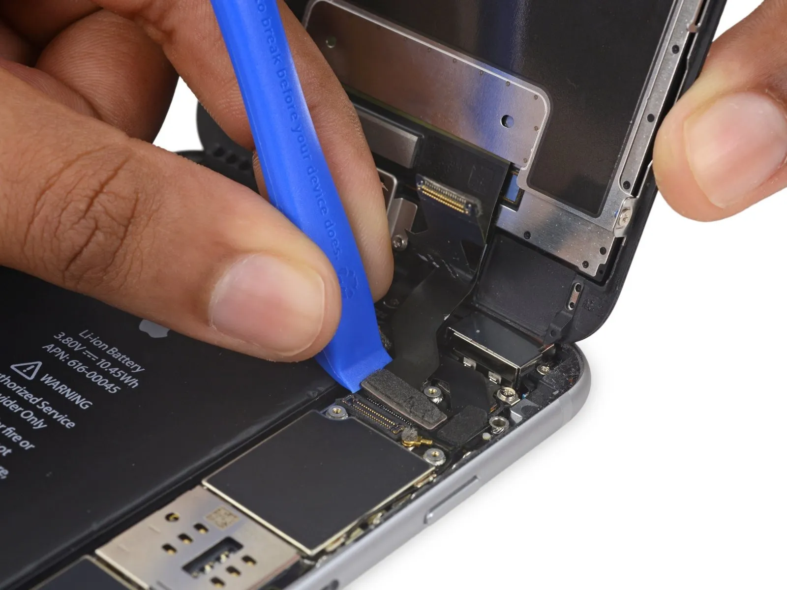

- Employ a 3/8-inch socket wrench to loosen the fastener, ensuring you apply consistent pressure to avoid damaging the threads, and always wear safety glasses to protect your eyes from potential debris.Use a plastic pry tool.Carefully separate the digitizer cable from its connection on the logic board by applying upward force.
- To ensure proper digitizer cable connection, avoid applying pressure to the connector's middle; instead, secure it by pressing one end, then the other, as this prevents component bending and potential damage.The display's touch functionality is impaired due to damage to the digitizer..
Step 23

- Prior to either detaching or reattaching the cable in this procedure, ensure the battery is disconnected.
- Using a prying tool, carefully release the home button/fingerprint sensor cable by lifting it vertically from its connector on the logic board.
Step 24
- Carefully detach the display assembly, ensuring no damage occurs.
- If you intend to substitute fresh adhesive along the display's perimeter during reassembly, stop at this point.
Step 25 | Remove the stretch-release adhesive
- Employ the specified tool to perform the action.Employ fine-tipped pliers or similar instruments for manipulation.Carefully use a tool or your fingers to lift the black pull tab from one of the adhesive strips.
- To prevent hazardous chemical leakage or fire risk, exercise caution and avoid using your tool to create holes or deform the battery.
Step 26

- Carefully draw the adhesive strip outward, maintaining a shallow angle and allowing ample time for it to separate completely from beneath the battery.
- Carefully attempt to recover any detached adhesive strip fragments with your fingers or a tool having a non-sharp, flat edge.Employ fine-tipped pliers or similar precision instruments.Maintain a steady pulling force, ensuring you avoid applying leverage beneath the battery.
- To aid in adhesive strip removal, the pull-tabs can be secured to a spudger.
- Continue removing the adhesive strips from the rest of the component, using the same method.
- Should the adhesive securing the battery become detached and unrecoverable, proceed to the subsequent procedure.
Step 27 | How to remove a stuck battery
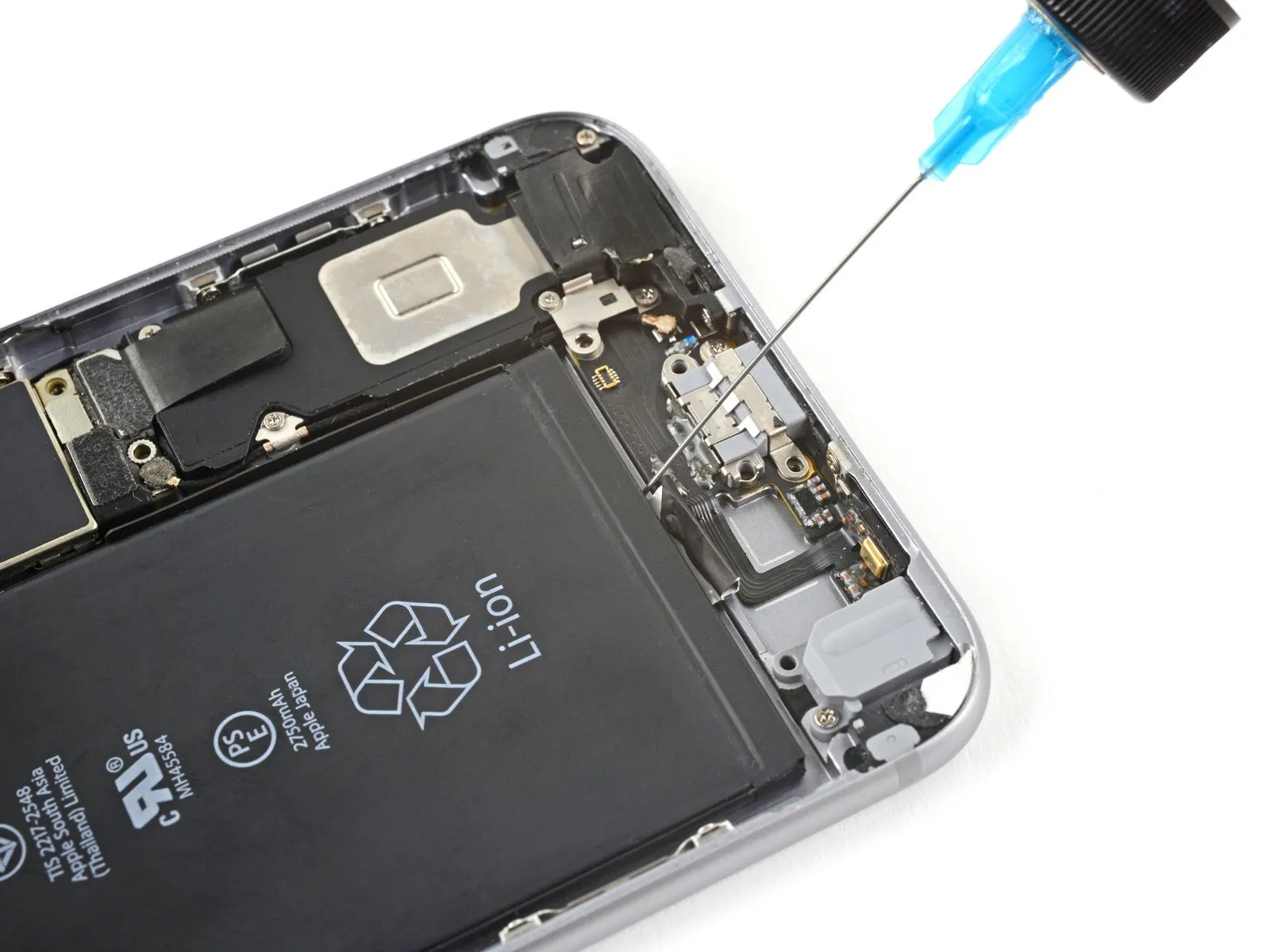

- To assist with battery removal if difficulties persist, carefully introduce a small amount of isopropyl alcohol—ensure it's at least 90% concentration—beneath the battery's edge, specifically targeting the location of the damaged adhesive strip(s).
- Angle the device upwards to direct the isopropyl alcohol towards the adhesive.
- Maintain pressure for a duration of 60 to 120 seconds, enabling the isopropyl alcohol to dissolve the bonding agent.
- Carefully lift the battery from its compartment using a plastic opening tool or the broad, flat edge of a spudger, applying gentle force.
Step 28
- Disconnect the power source by detaching the battery.
- Carefully slide the protective plastic covering off the new battery, ensuring you don't snag or damage the ribbon cable during removal.
- To prevent damage, ensure any residual alcohol solution is completely removed by wiping with a clean cloth or by permitting full evaporation before proceeding with the new battery installation.
- To guarantee correct positioning within its designated space, briefly plug the battery connector back into the logic board's socket prior to securing the new battery.
- Secure the battery in place, then sever its electrical connection before proceeding with the remaining reassembly steps.
- To secure a battery lacking factory-applied adhesive, follow the instructions in this guide for adhesive strip replacement.
- Following reassembly, execute a complete system reset to proactively avoid potential problems and streamline any subsequent diagnostic procedures.
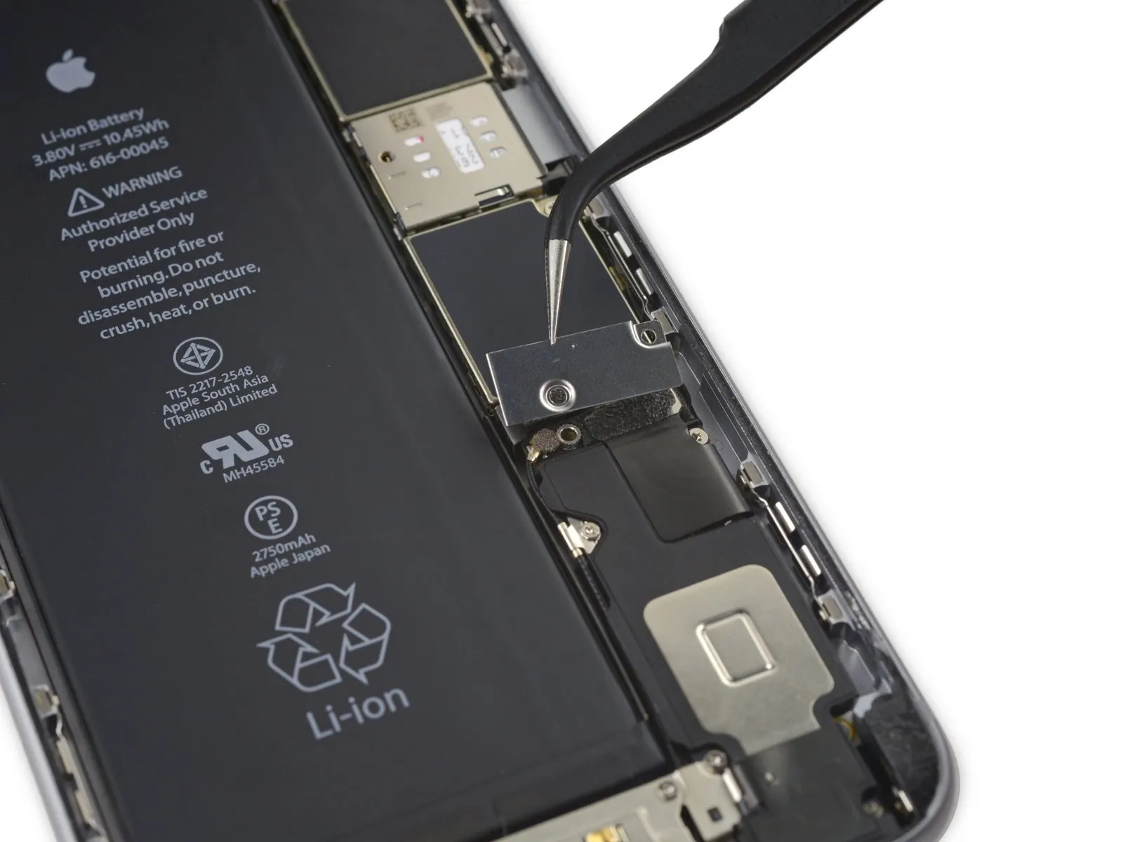
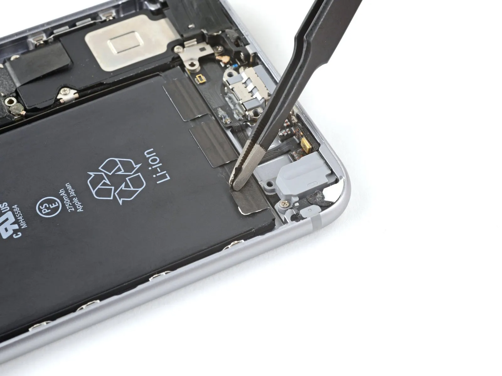
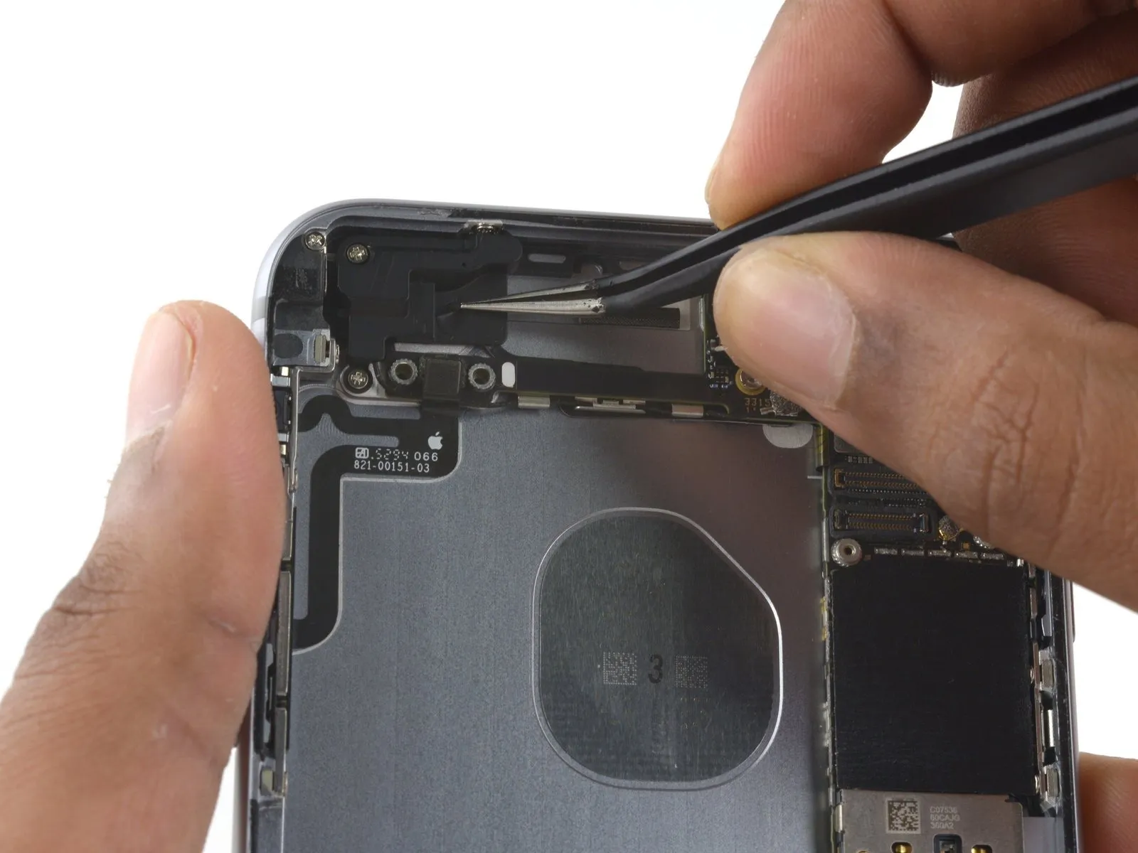
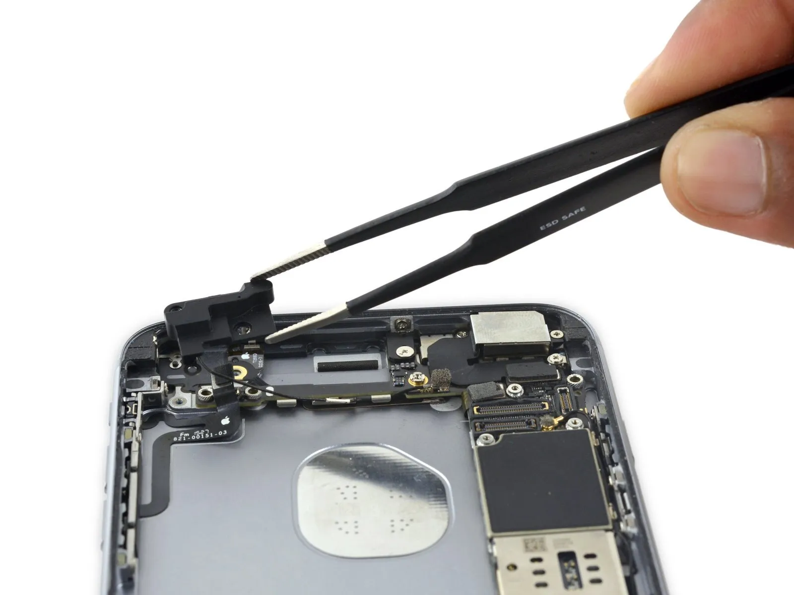
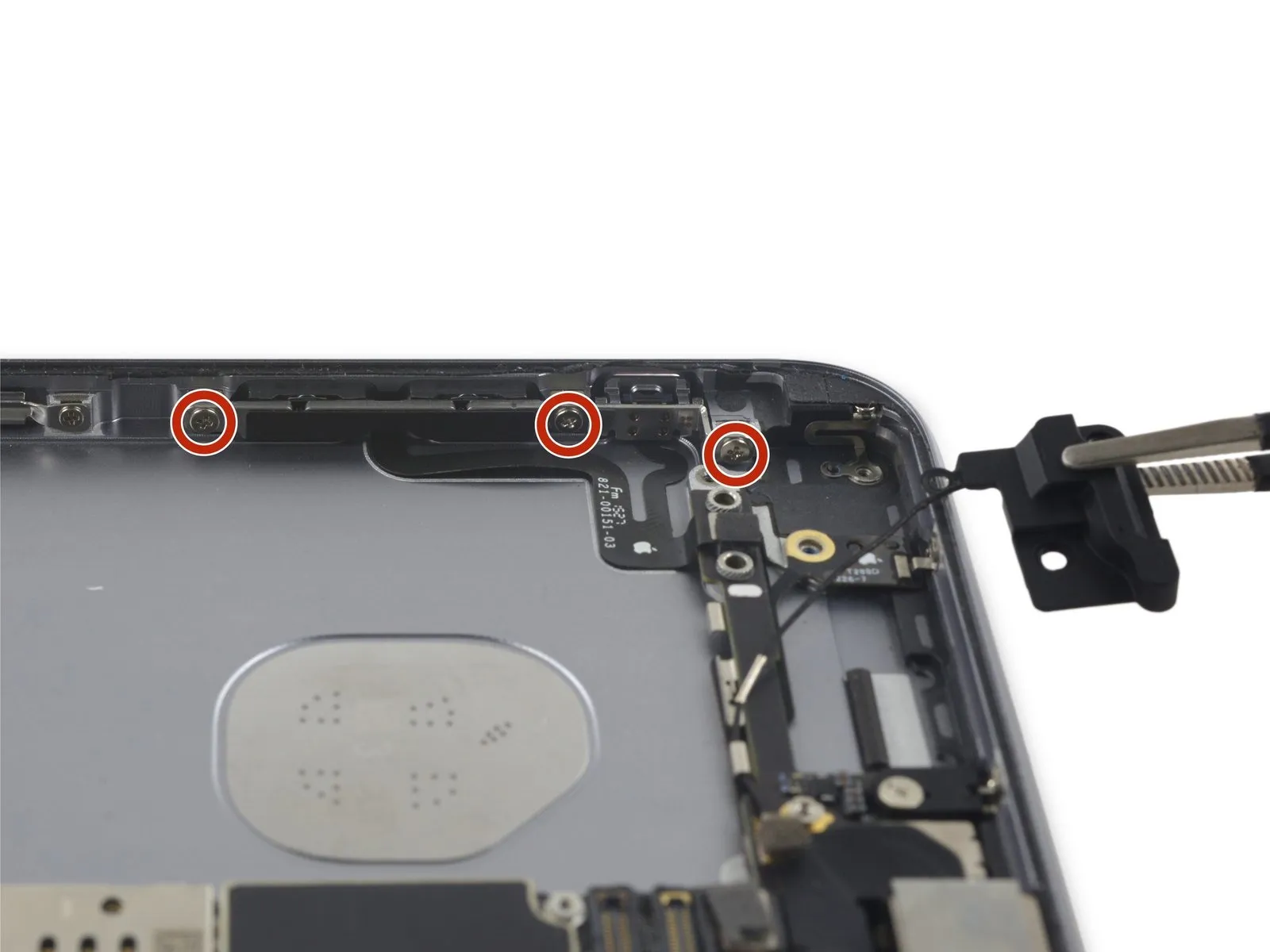
Step 29 | Volume Control Cable
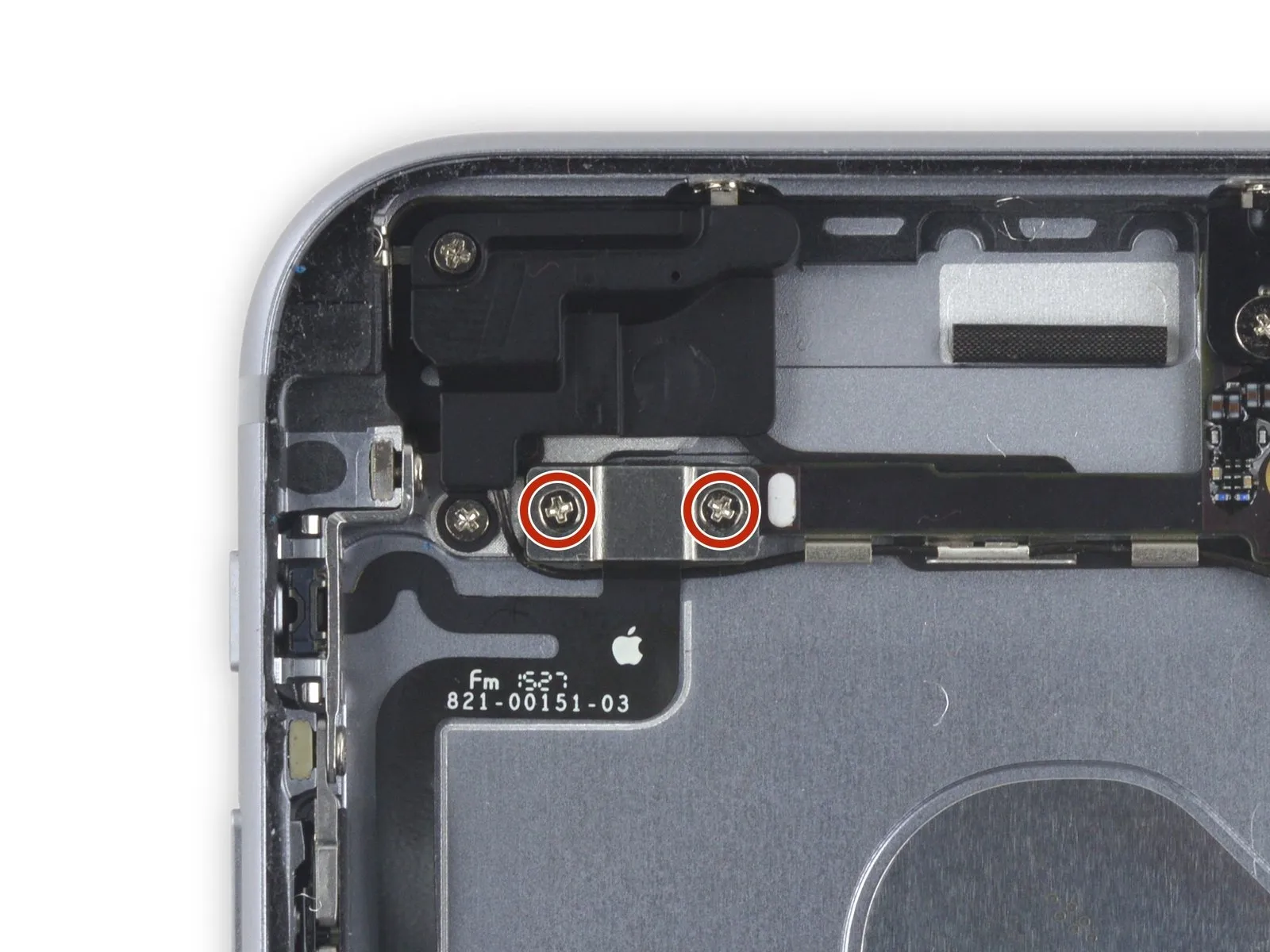
- Using a Phillips screwdriver, detach the two screws, each measuring 2.7 mm, located above the audio control cable bracket.
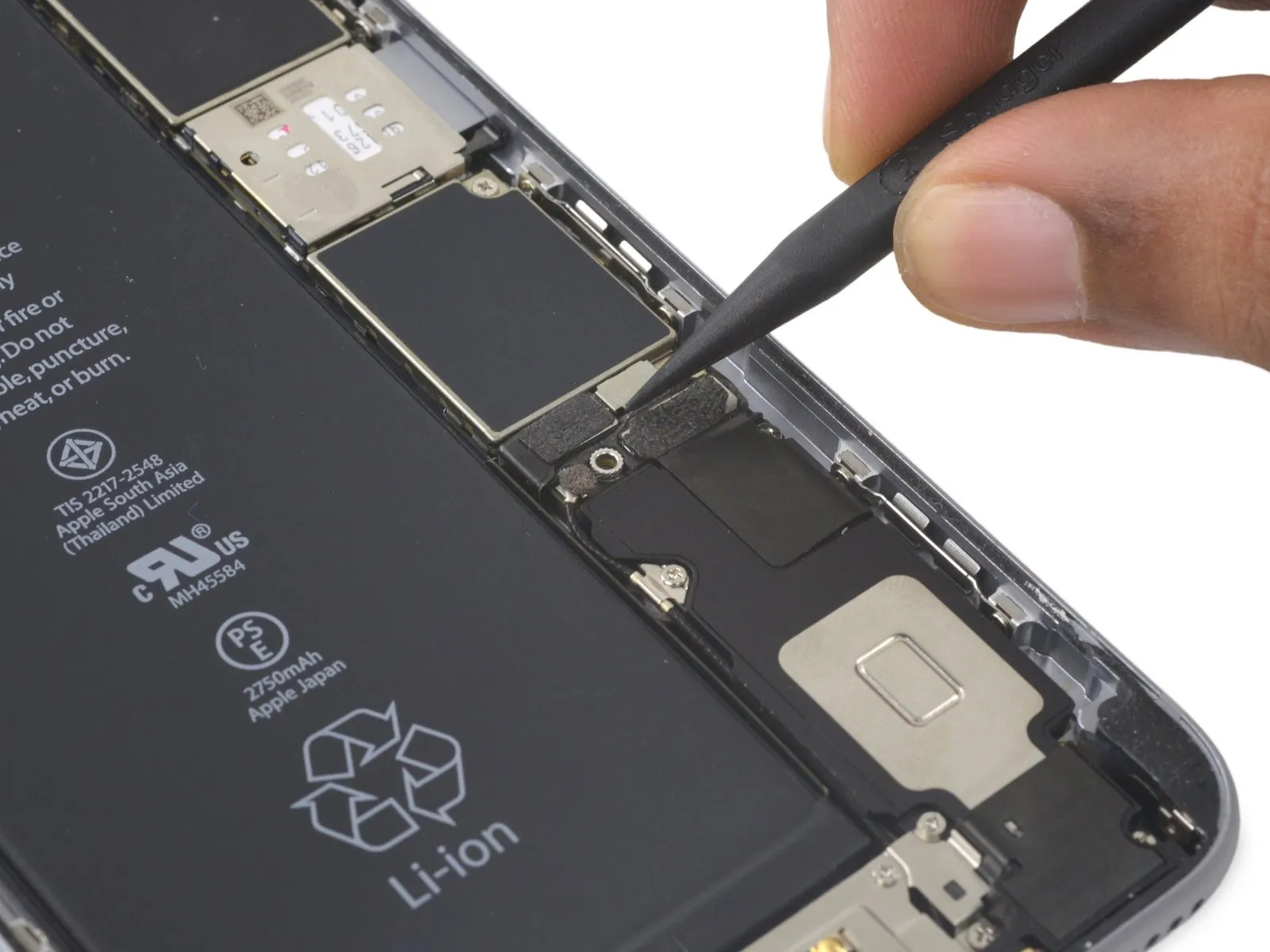
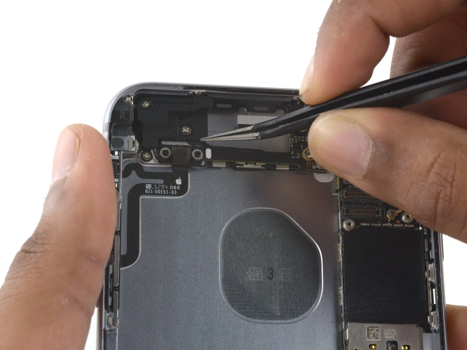
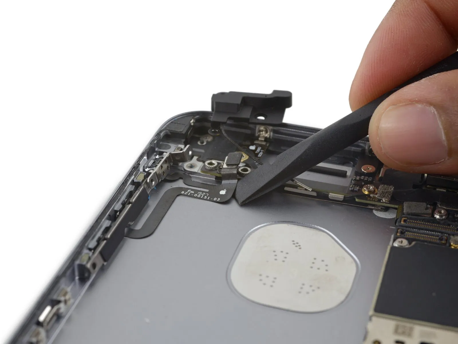
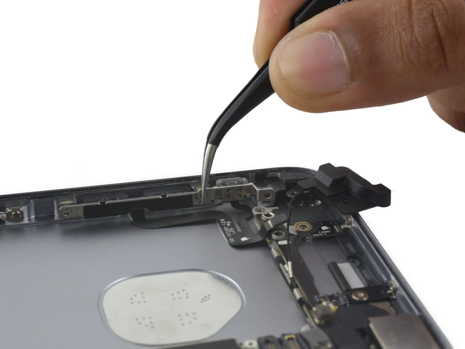
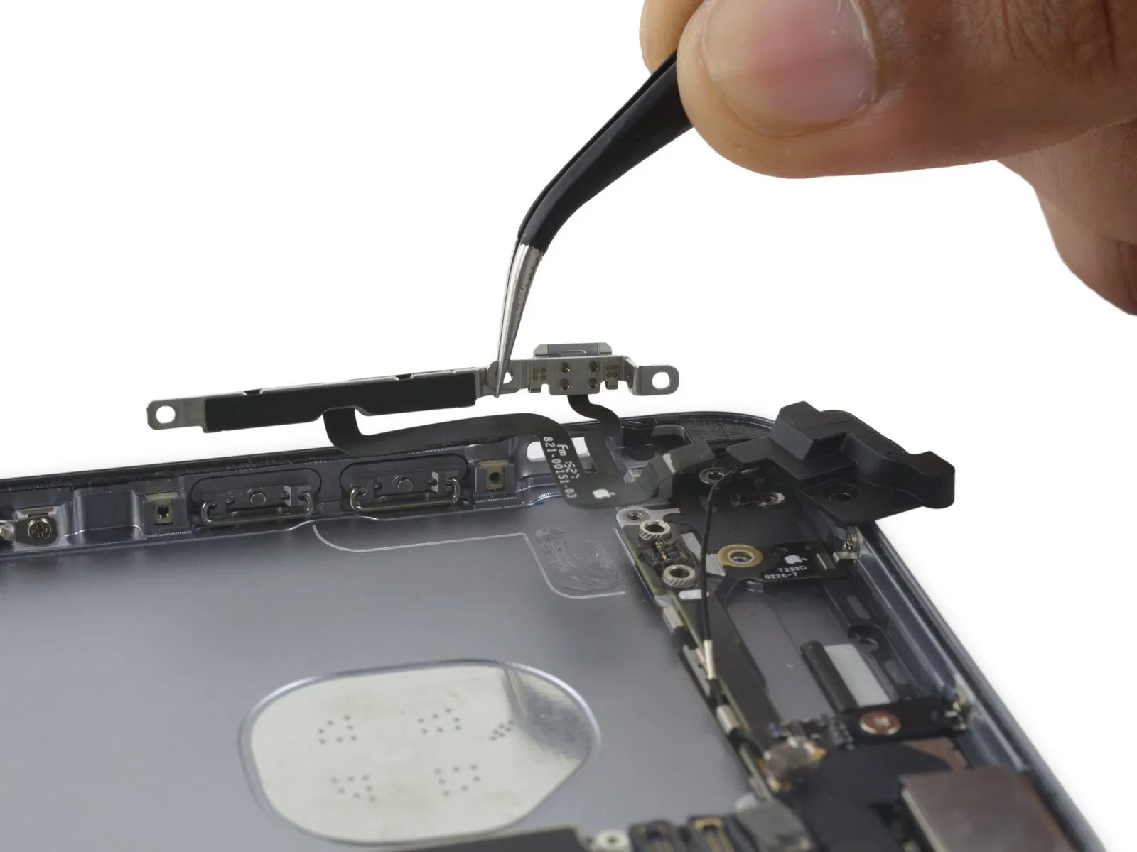
Step 30
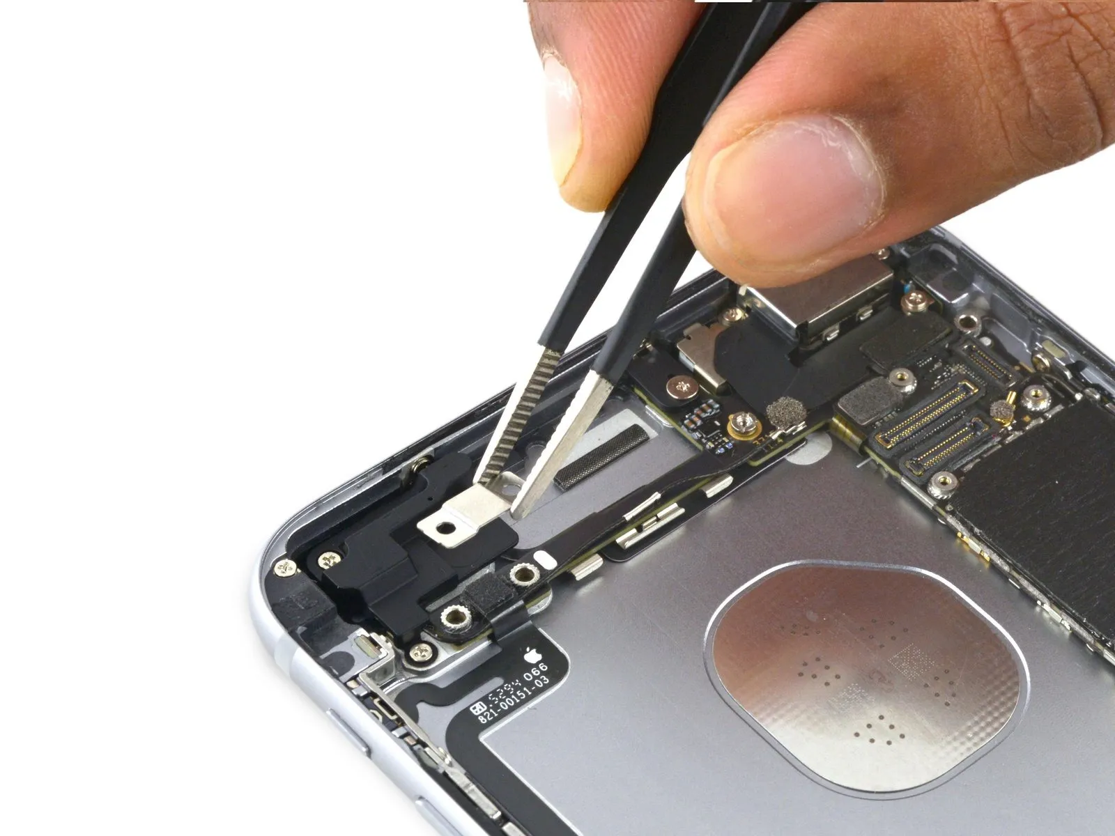
- Detach the bracket securing the audio control cable.
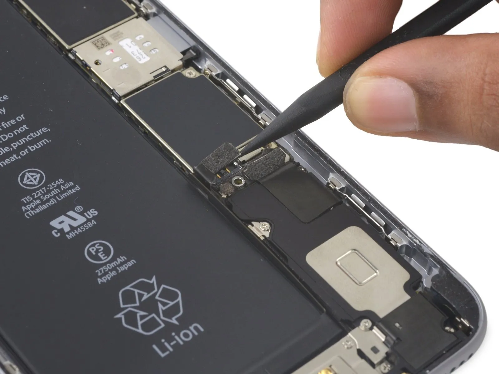
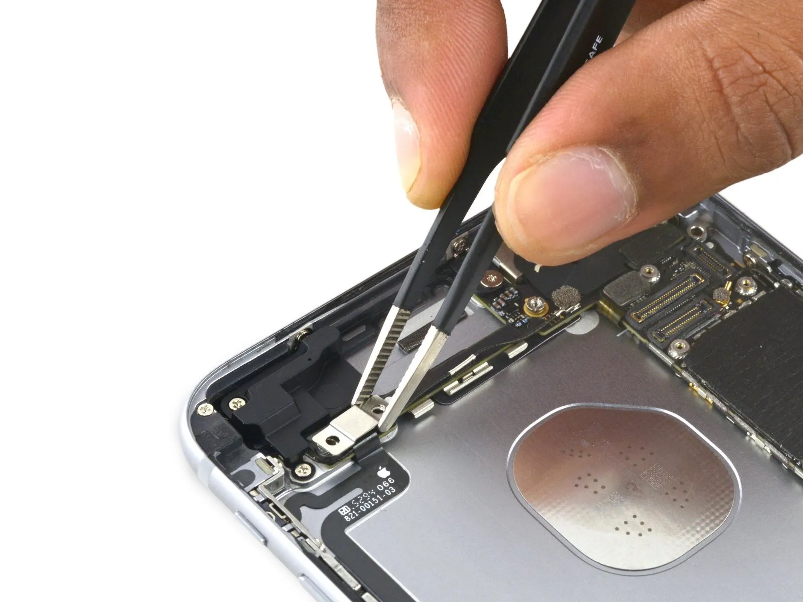
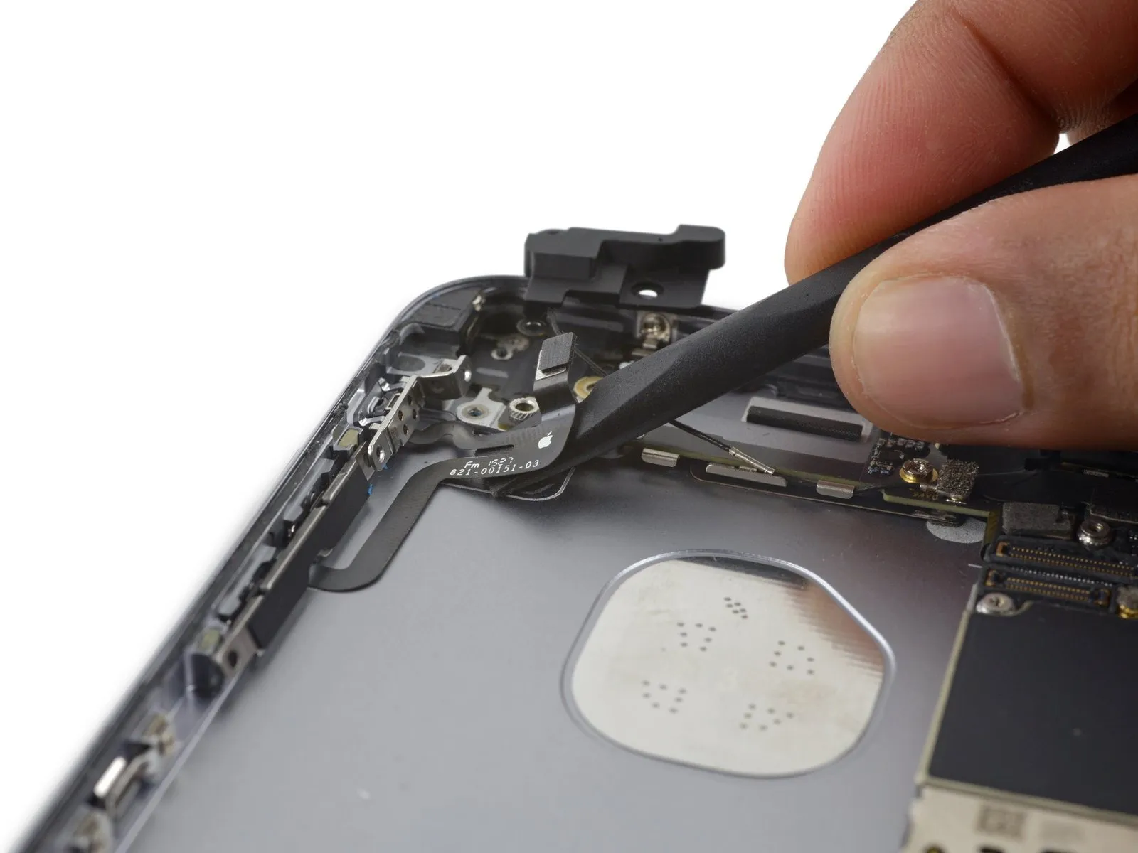
Step 31

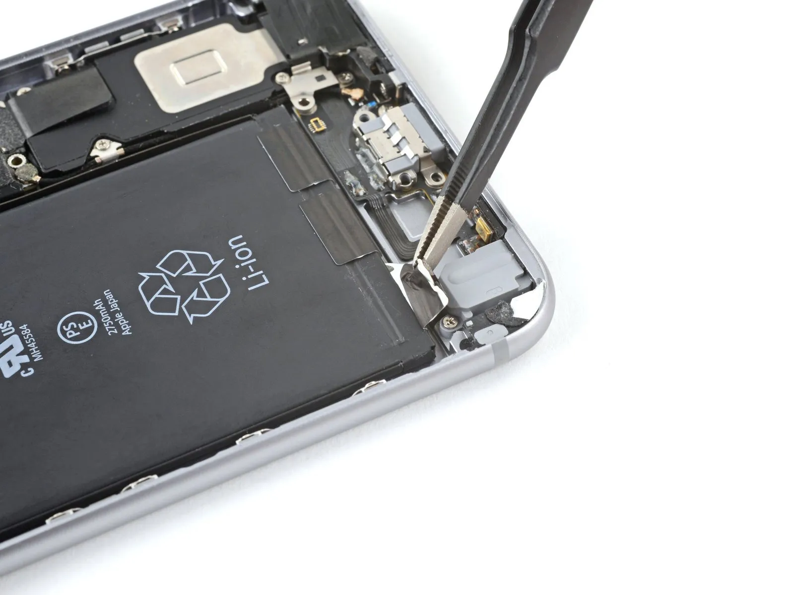
- Carefully detach the audio control flex cable from the connector located on the logic board.
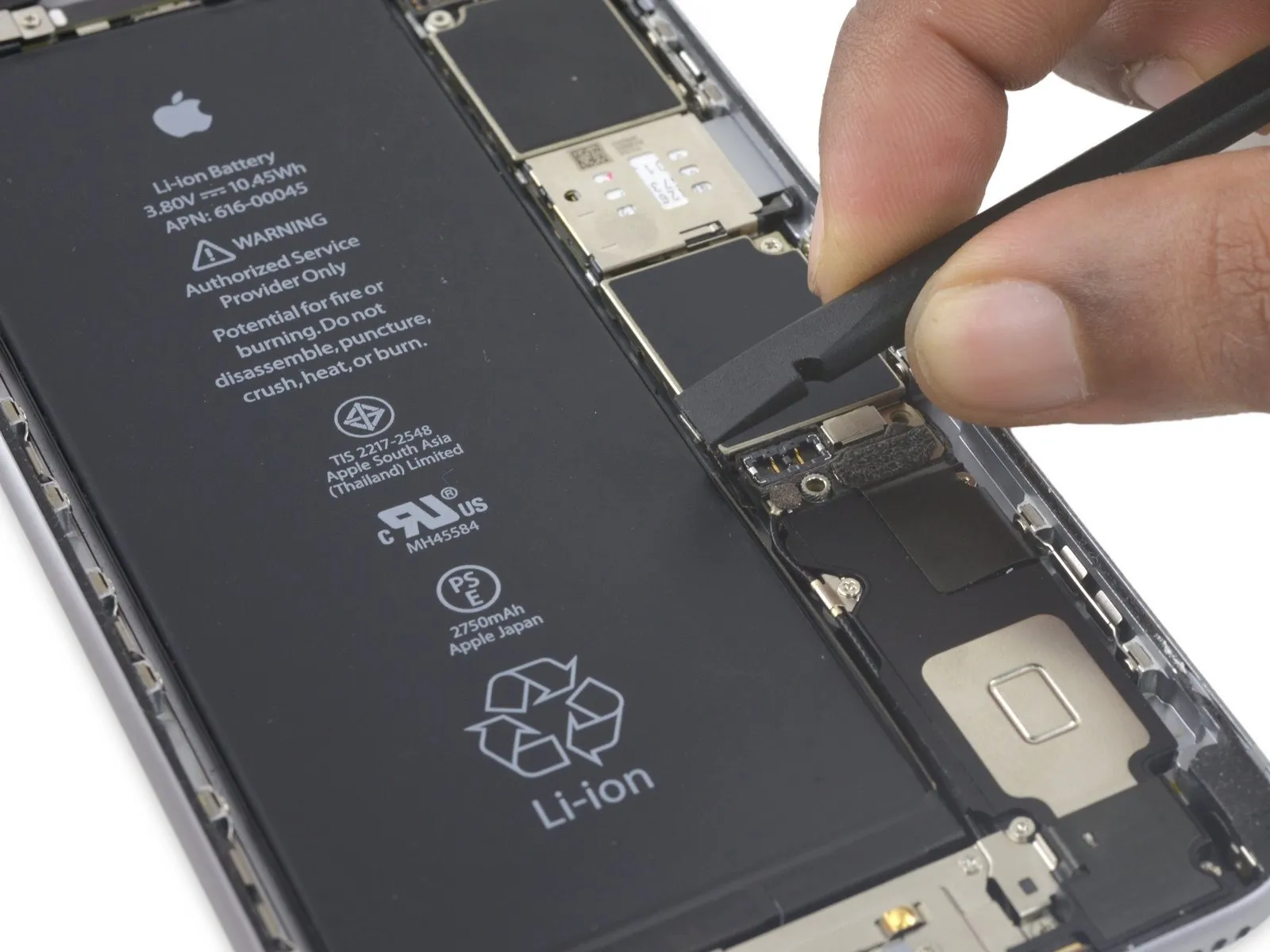
Step 32
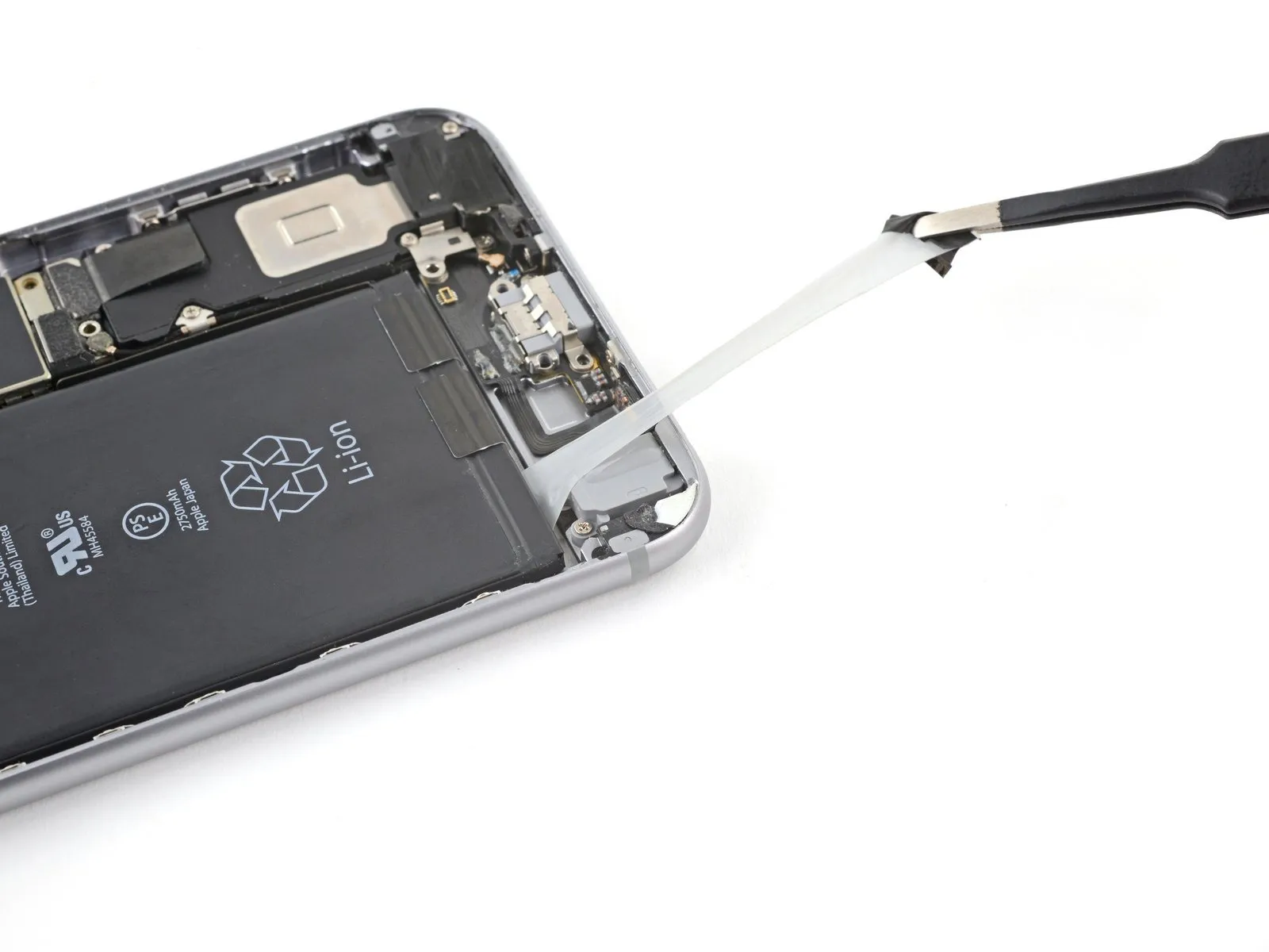
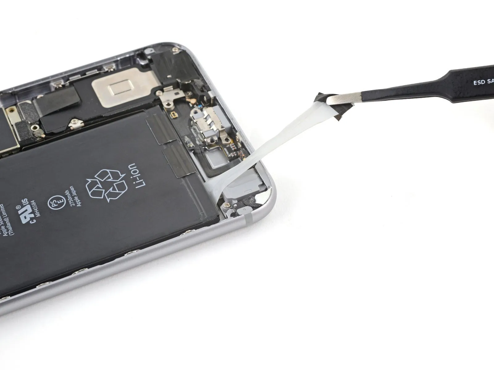
- Carefully peel away the round adhesive label that conceals the screw holding the cellular antenna in place on the back cover.
Step 33
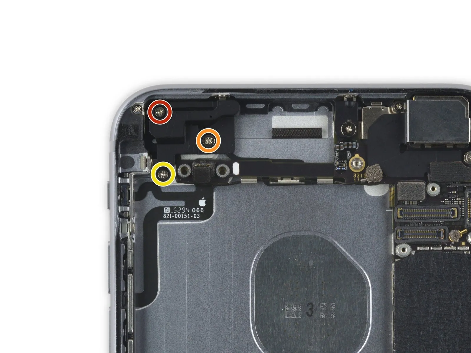
- A screw with a 2.7-millimeter head diameter is required.
- A screw with a 1.7 mm diameter is required.
- A screw with a 1.3-millimeter head diameter is required.
Step 34

Step 35
- Use three Phillips screws, each measuring 2.4 millimeters.Position the audio control cable bracket atop the audio control cable.
Step 36
Step 37
- Carefully disconnect the volume control flex cable from the circuit board.
- Two distinct components are joined together using a ribbon cable to form the cable assembly.Adjust the audio level using the designated buttons.Using appropriate safety precautions, carefully connect the 12-inch length of blue wire to terminal J4, then secure it with the 0.25-inch crimp connector and ensure a firm connection before proceeding.Employ a momentary switch to prevent the device from emitting audible clicks during operation..