iPhone 7 camera lens replacement
Prior to commencing any repair work, disconnect the device completely from all electrical power.
- To complete this repair, you will need the following tools:Utilize a Phillips head screwdriver.
Consult the user manual to find model-specific information and extra safety guidelines.
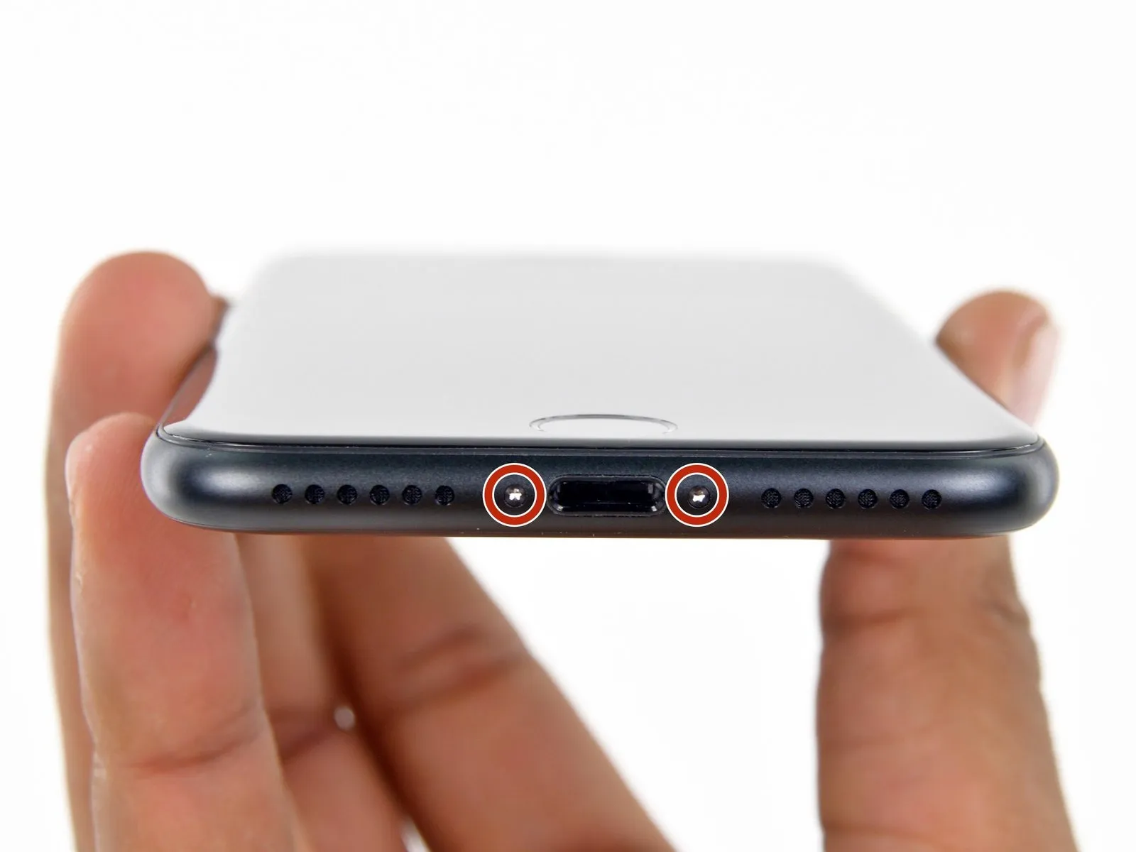
Step 1 | Pentalobe Screws
- To ensure optimal performance during the repair process, deplete the iPhone's battery to a level below 25% prior to commencing work.A lithium-ion battery must be fully charged.A puncture can result in combustion and/or a forceful rupture.
- To prevent electrical shock or damage, ensure the iPhone is completely de-energized prior to starting the repair process.
- Using appropriate tools, detach the iPhone's bottom edge by unscrewing the pair of 3.4 mm pentalobe fasteners.
- Removing the display assembly will damage the iPhone's water resistance; ensure replacement seals are available for installation prior to proceeding, or exercise extreme caution to prevent liquid ingress if reinstalling the display without new seals.
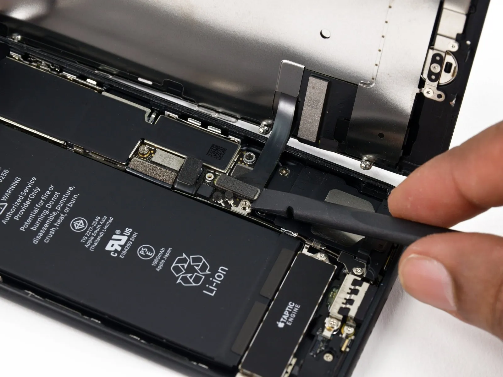
Step 2 | Display Assembly
- Prior to either detaching or reattaching the cables in this procedure, ensure the battery is fully disconnected.
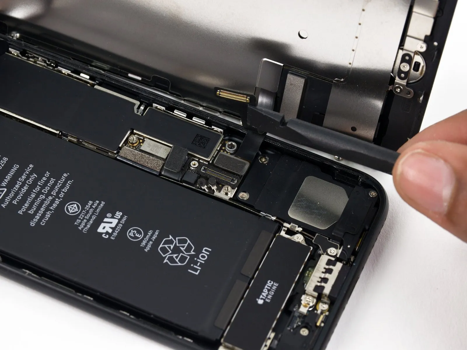
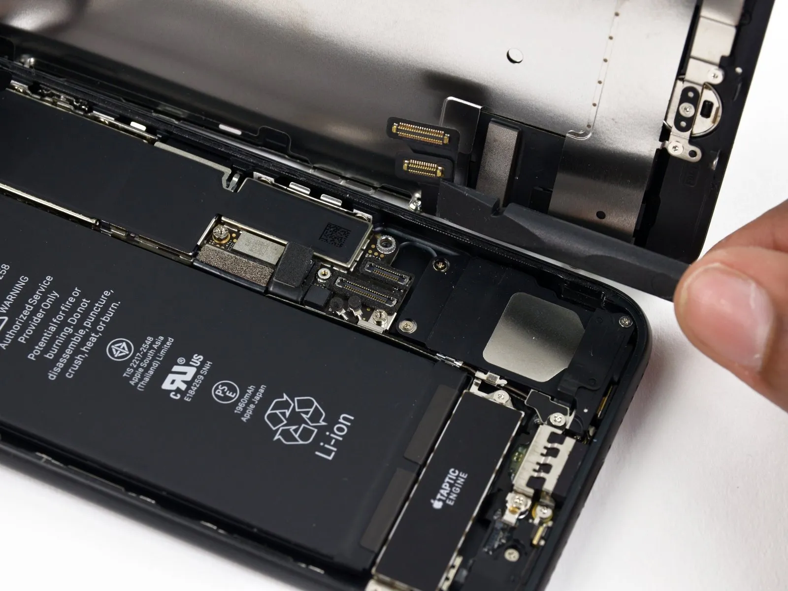
- Carefully detach the two display connectors located on the logic board's lower section; employ a spudger or fingernail to lift them vertically from their respective sockets.
- Ensure both ends of the cable are firmly seated by applying even pressure until a distinct click is heard; avoid applying pressure to the central portion of the connector. Slight misalignment during connection can result in bending and irreversible damage.
- Following reassembly, a non-functional display—characterized by a blank screen, white lines, or unresponsive or limited touch functionality—may be resolved by carefully disengaging and then firmly reseating both display cables to ensure proper connection.
Step 3
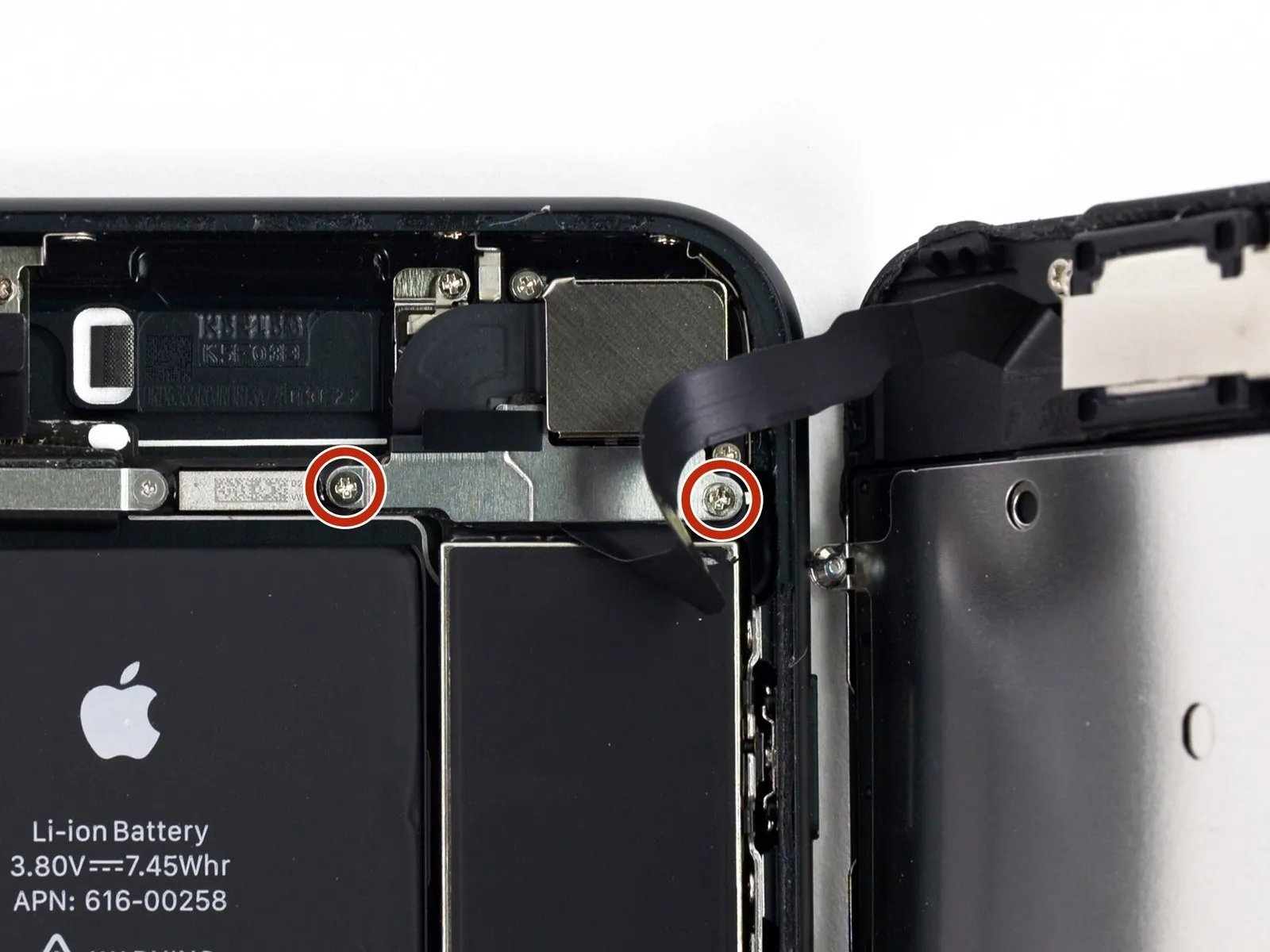
- Using a Phillips #000 screwdriver, detach the bracket that covers the front panel sensor assembly connector by unscrewing the two 1.3 mm screws holding it in place.
- Certain phone models may have a Y000 component, which Apple began incorporating.Using a 5mm hex key, carefully tighten the screw to a torque of 1.2 Nm, ensuring not to overtighten and potentially damage the retaining clip.Eventually, during the product's operational period, this component will require replacement.
Step 4
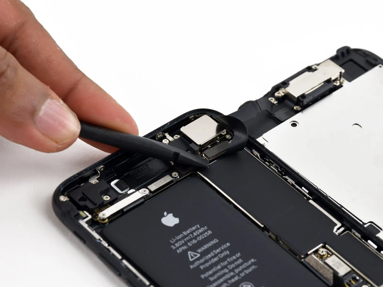

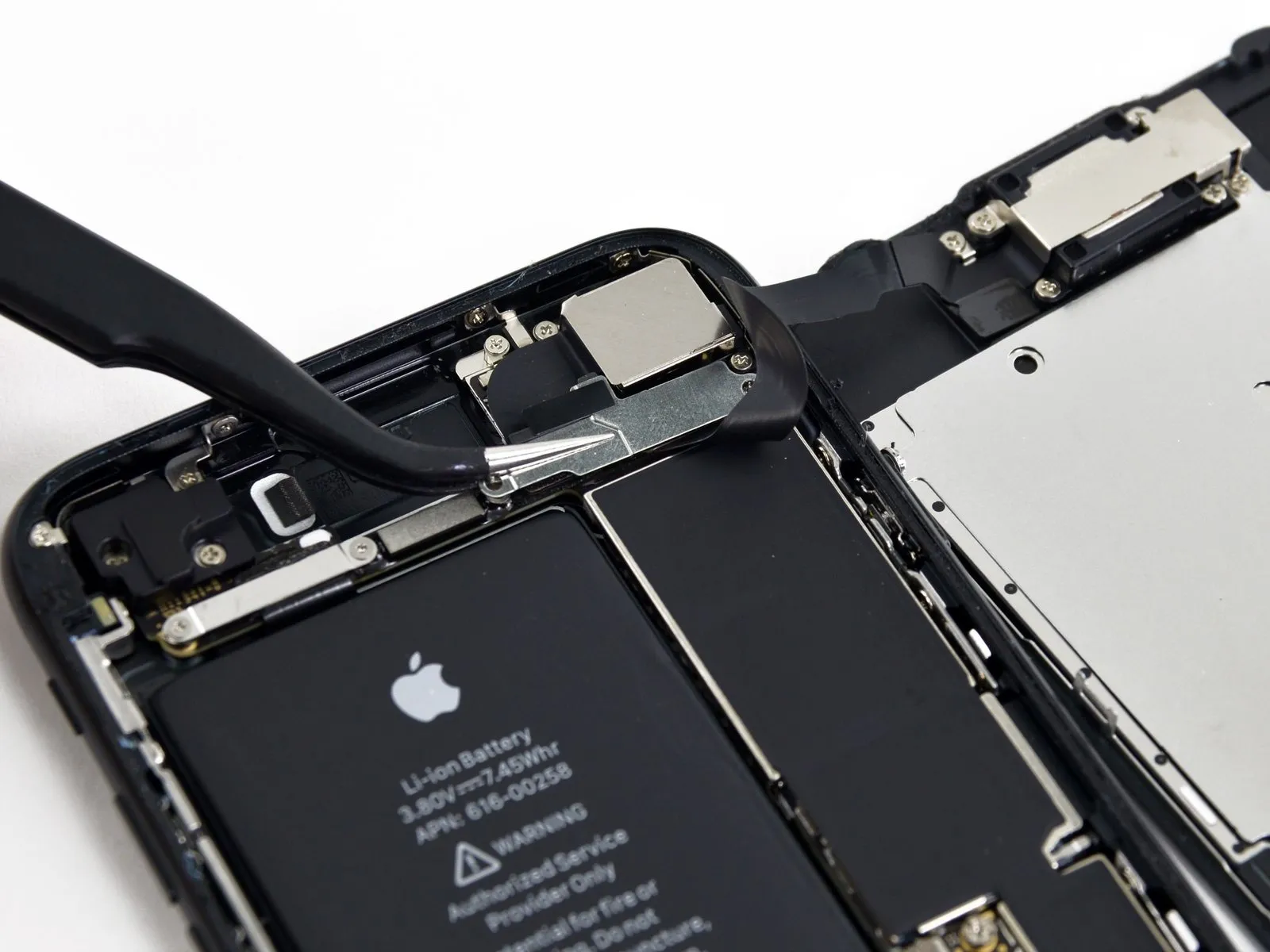
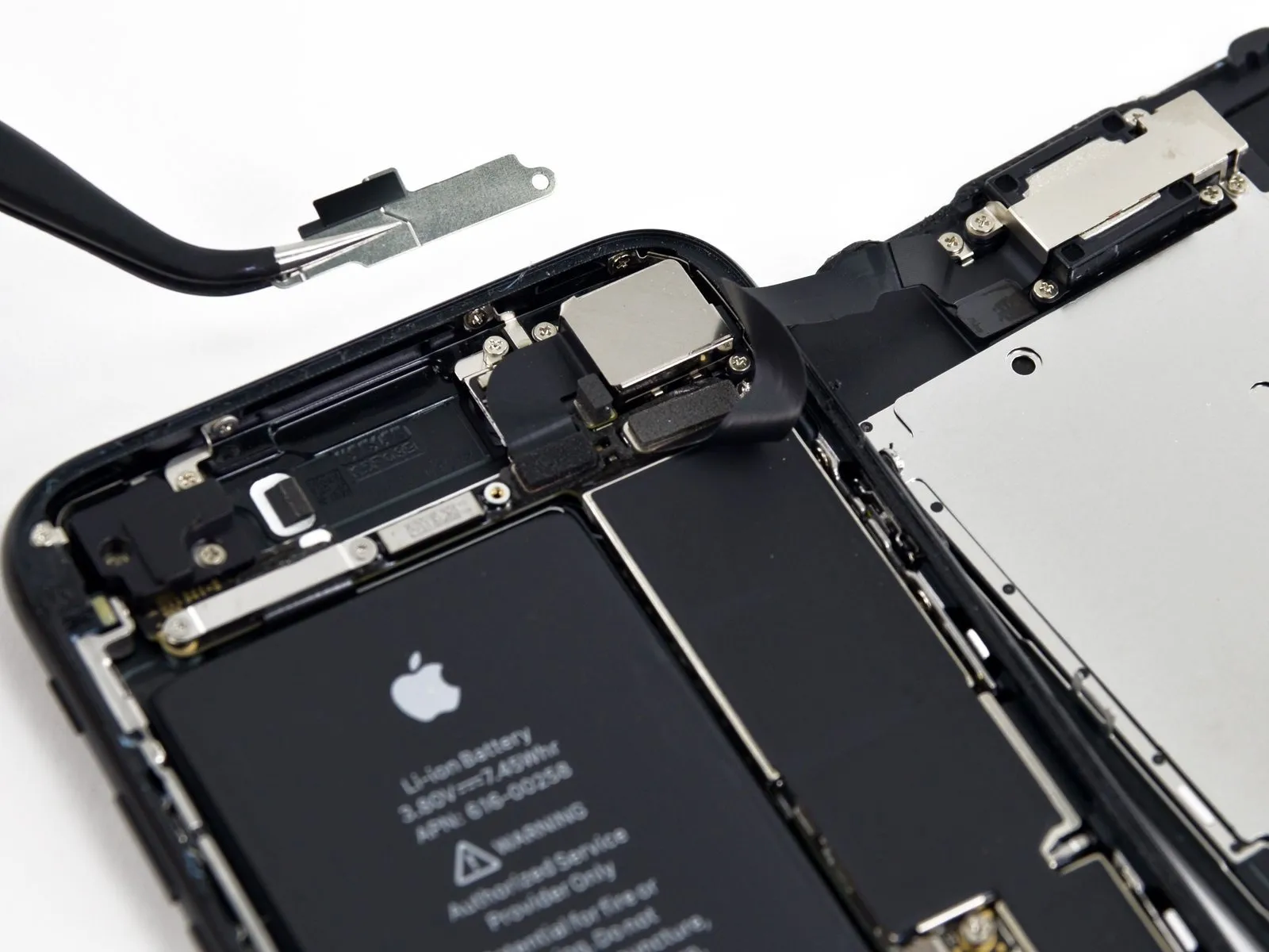
- Carefully detach the connector linking the front panel sensor assembly to its socket on the logic board.
- To reduce the chance of deformation, reconnect the press connector sequentially, working one end at a time.
Step 5
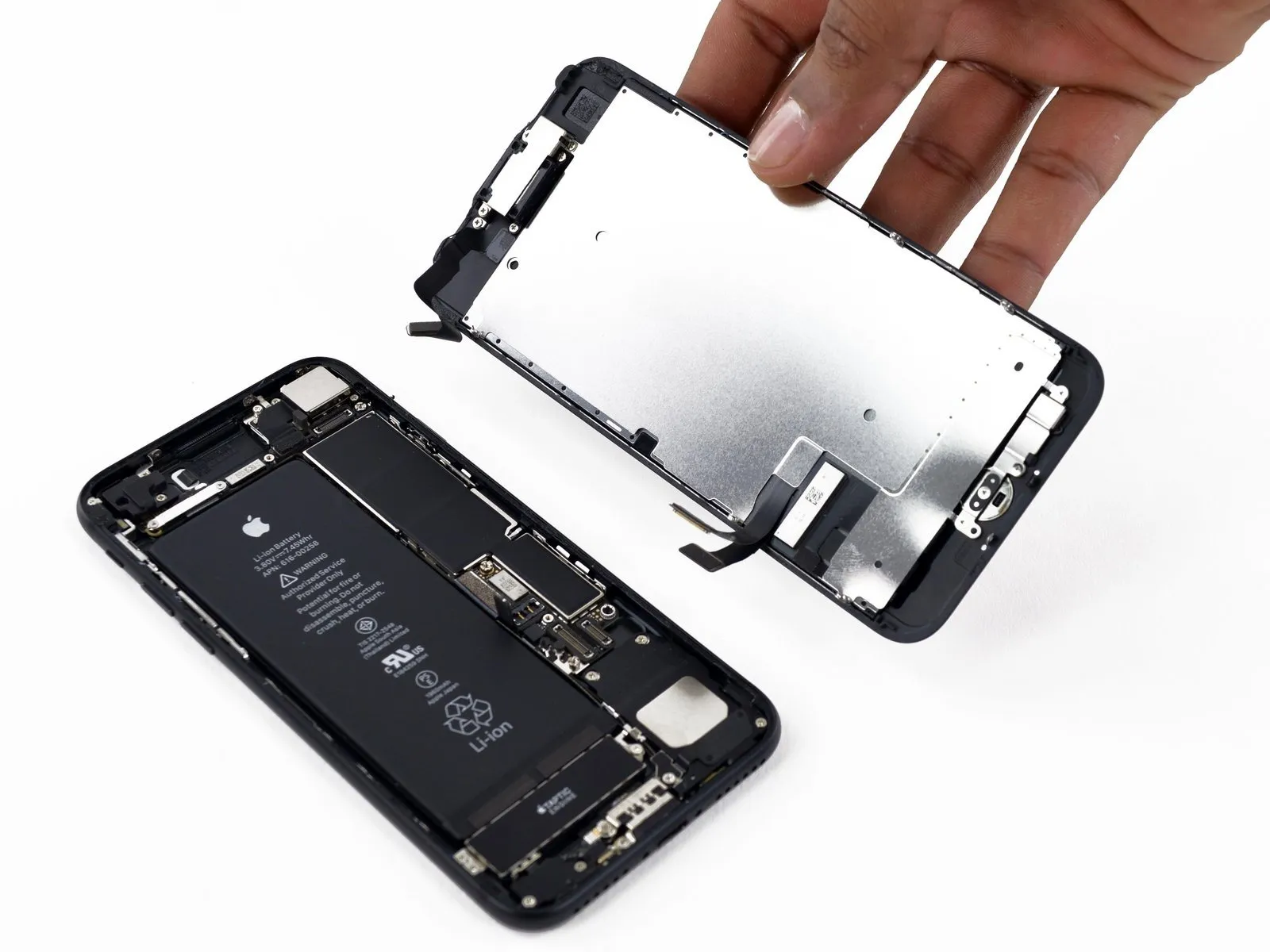
- Carefully detach the display assembly, ensuring no damage occurs.
- If you intend to substitute fresh adhesive along the display's perimeter during reassembly, stop at this point.
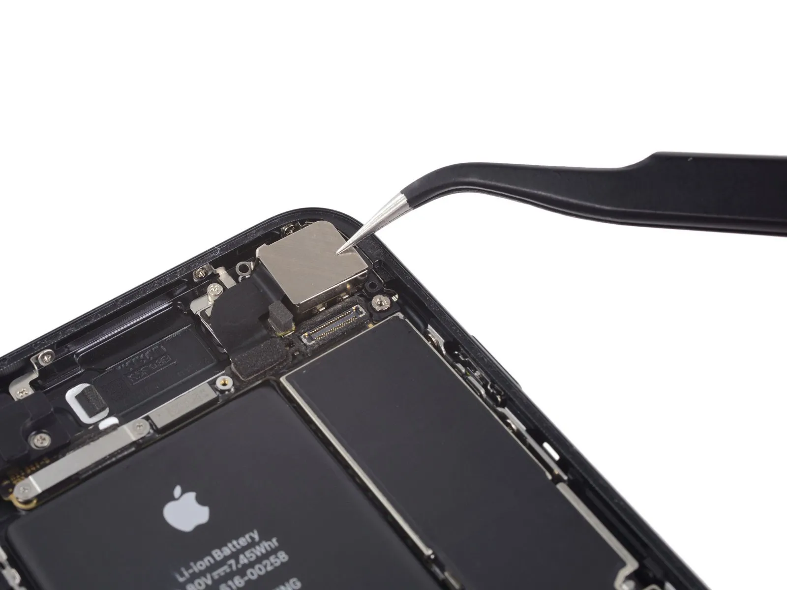
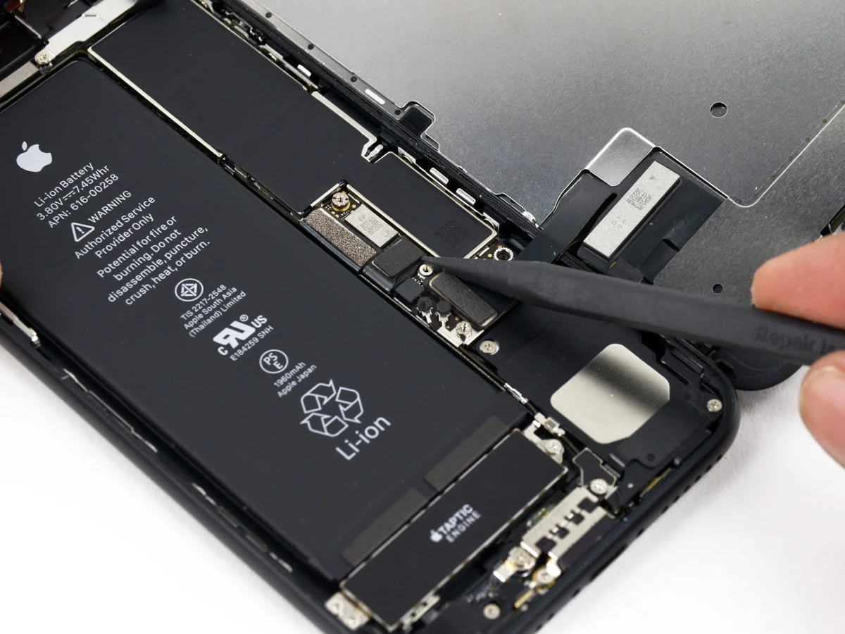
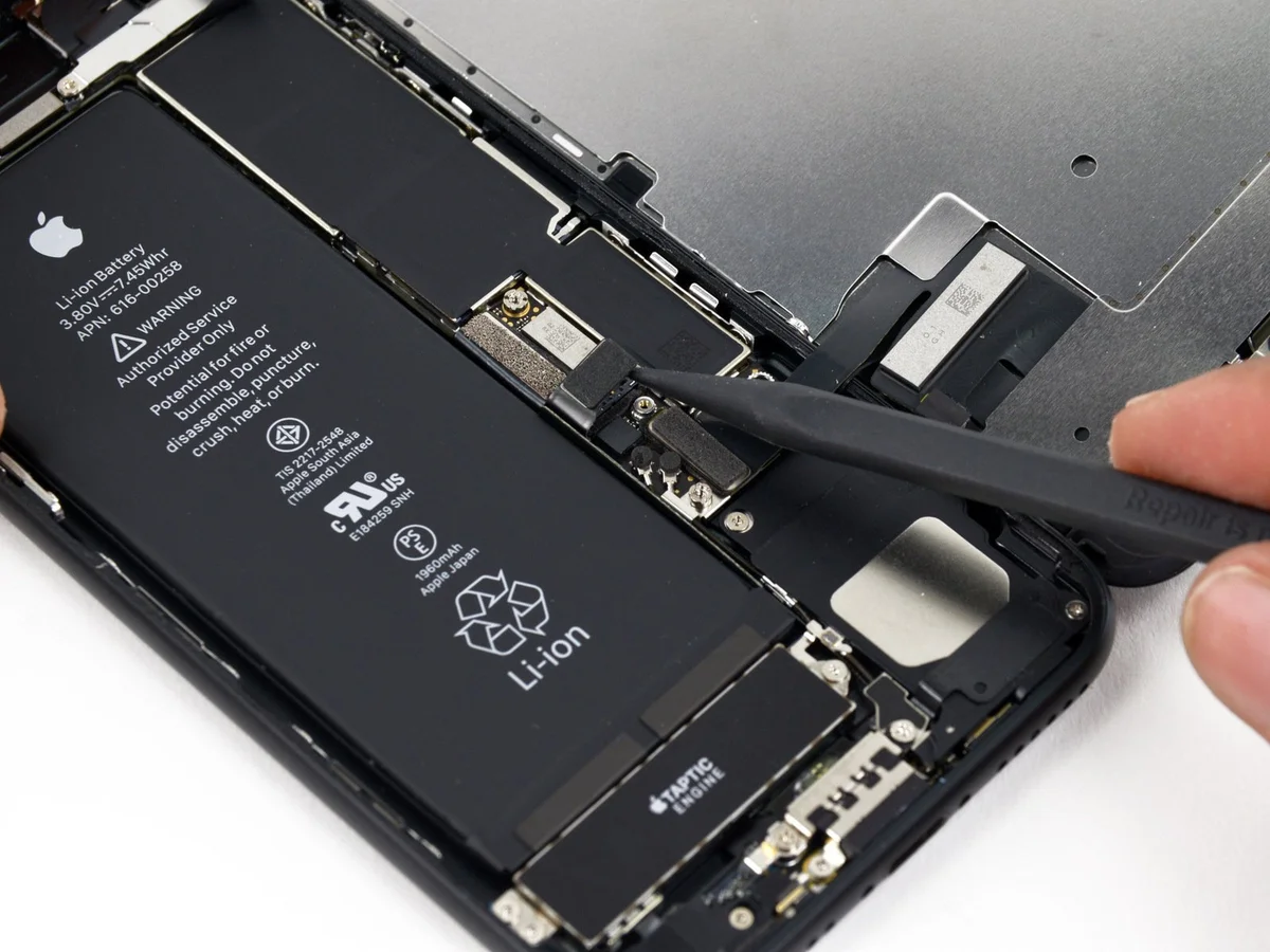
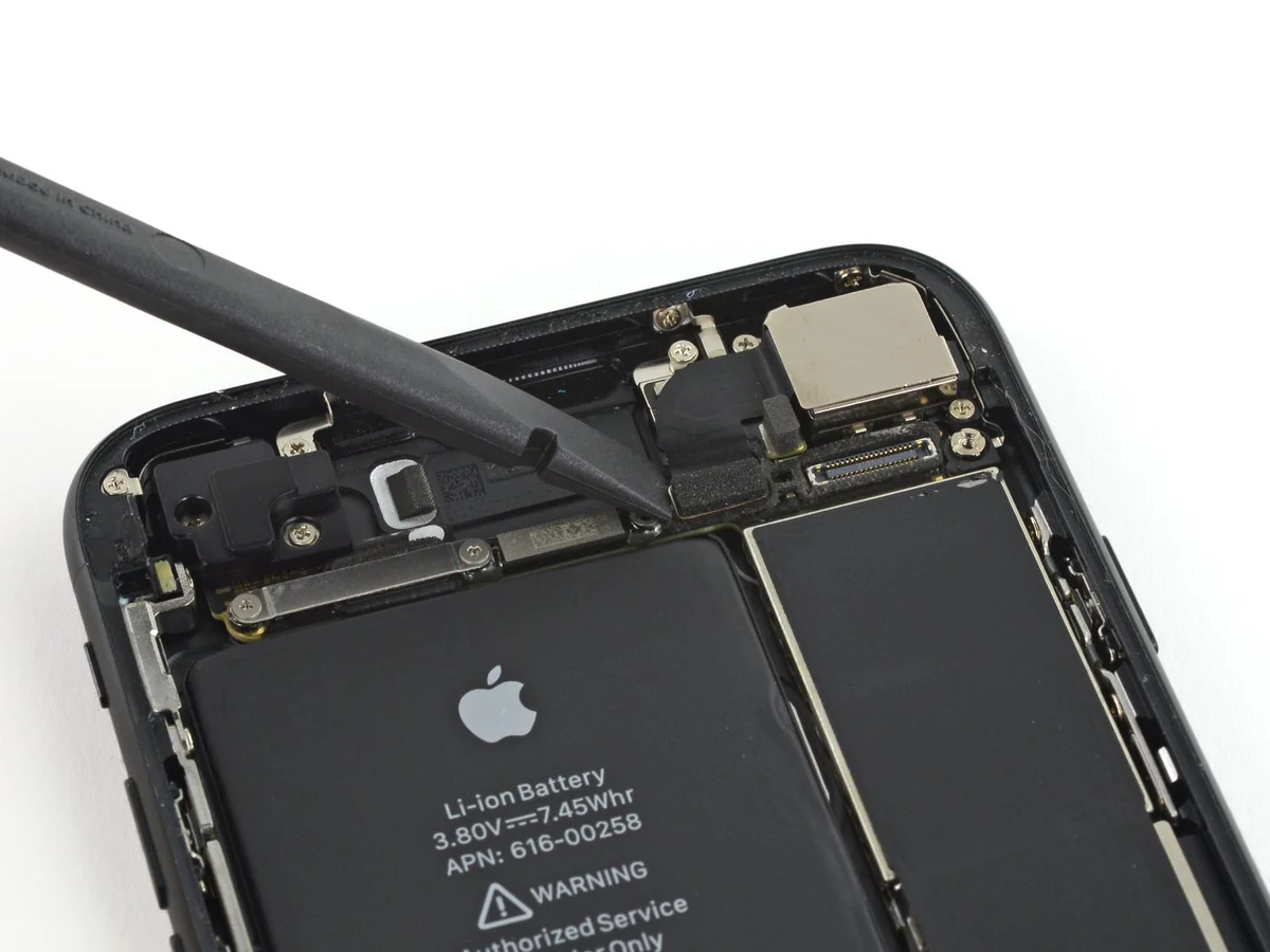
Step 6 | Rear Camera


Employ the tool's straight, planar edge.Use a plastic pry tool, often referred to as a spudger.Carefully separate the rear camera's connector from its corresponding socket on the logic board.
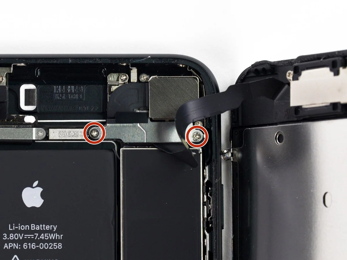
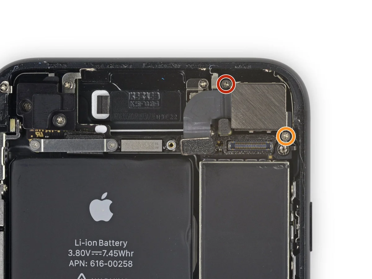
Step 7

Detach the listed components.Use a Phillips head screwdriver.Affix the rear camera bracket to the camera module, ensuring proper alignment.
- Begin the process by executing the action designated as "one."Utilize a screw with a diameter of 1.3 millimeters.
- Begin the process by executing the singular action.A screw with a diameter of 2.5 millimeters.
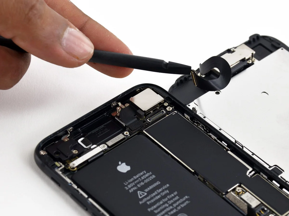
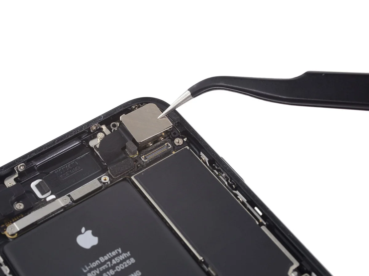
Step 8
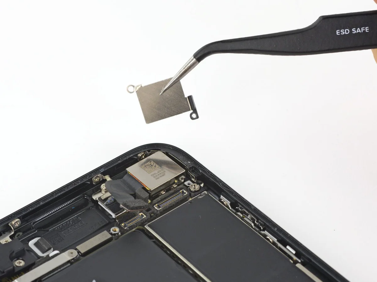
Detach the bracket.
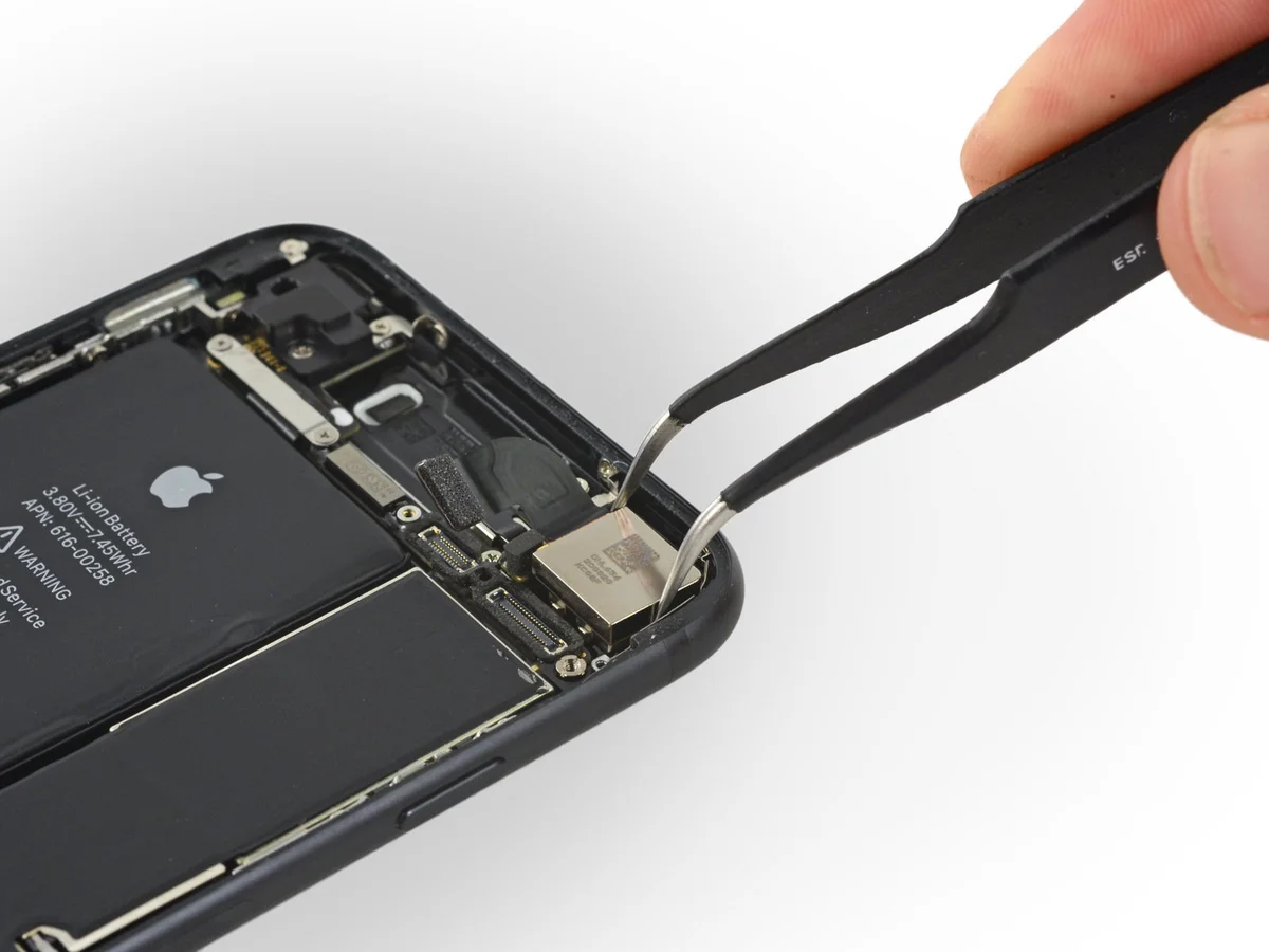
Step 9

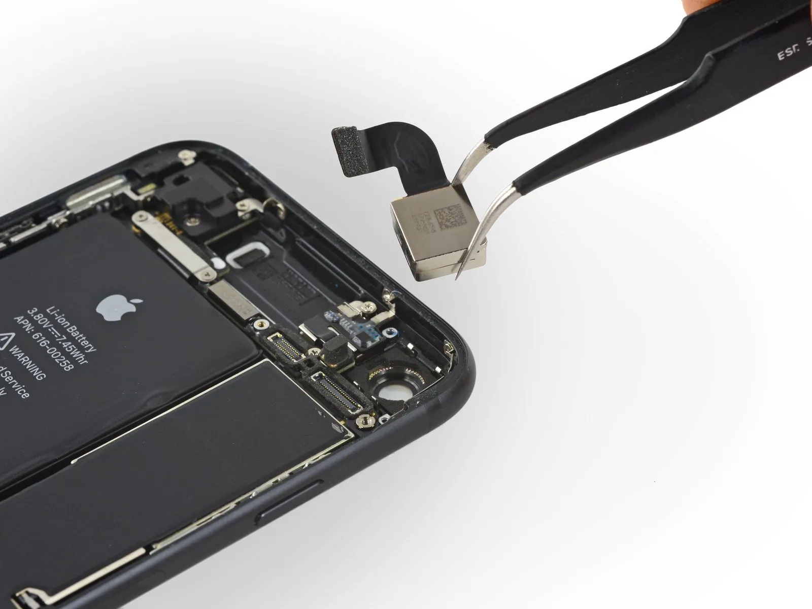
Carefully detach the rear camera assembly.
Step 10 | Pentalobe screws

- To begin the repair process, ensure your iPhone's battery level is reduced to below 25% to prevent potential hazards.Accidental puncture of a lithium-ion battery that holds a charge carries a risk of fire and/or explosion.
- Prior to disassembly, ensure your iPhone is completely powered down.
- Removing the iPhone's screen compromises its water resistance; failure to substitute the gaskets afterward will eliminate the device's waterproof capabilities.
- Using appropriate tools, detach the two screws, each measuring 3.4 mm in diameter and featuring a pentalobe head, located on the device's lower edge.
Step 11 | Opening procedure
Using a 5/32-inch hex key, carefully tighten the four retaining screws securing the motor assembly to the gearbox housing, ensuring each is snug but not overtightened to prevent damage; observe a torque of 6 in-lbs per screw.
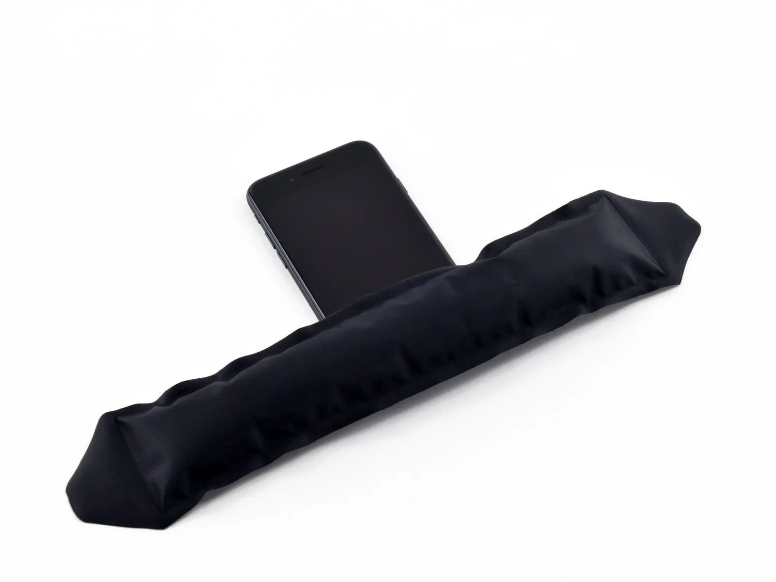
Apply heat from an iOpener to the lower edge of the device's rear casing to loosen the adhesive securing the display assembly.
Allow approximately 60 seconds for the adhesive to reach operating temperature before continuing.
Apply heat from an iOpener to the lower edge of the device's rear casing to loosen the adhesive securing the display assembly.
Allow approximately 60 seconds for the adhesive to reach operating temperature before continuing.
Step 12

Using a 5/32-inch hex key, carefully tighten the four retaining screws securing the fan assembly to the motor housing, ensuring each is snug but not over-tightened to avoid damaging the threads; observe a torque of 3.5 inch-pounds per screw.
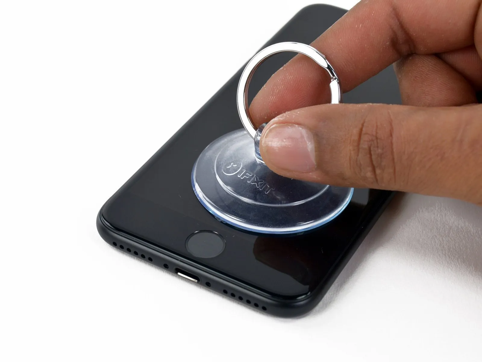
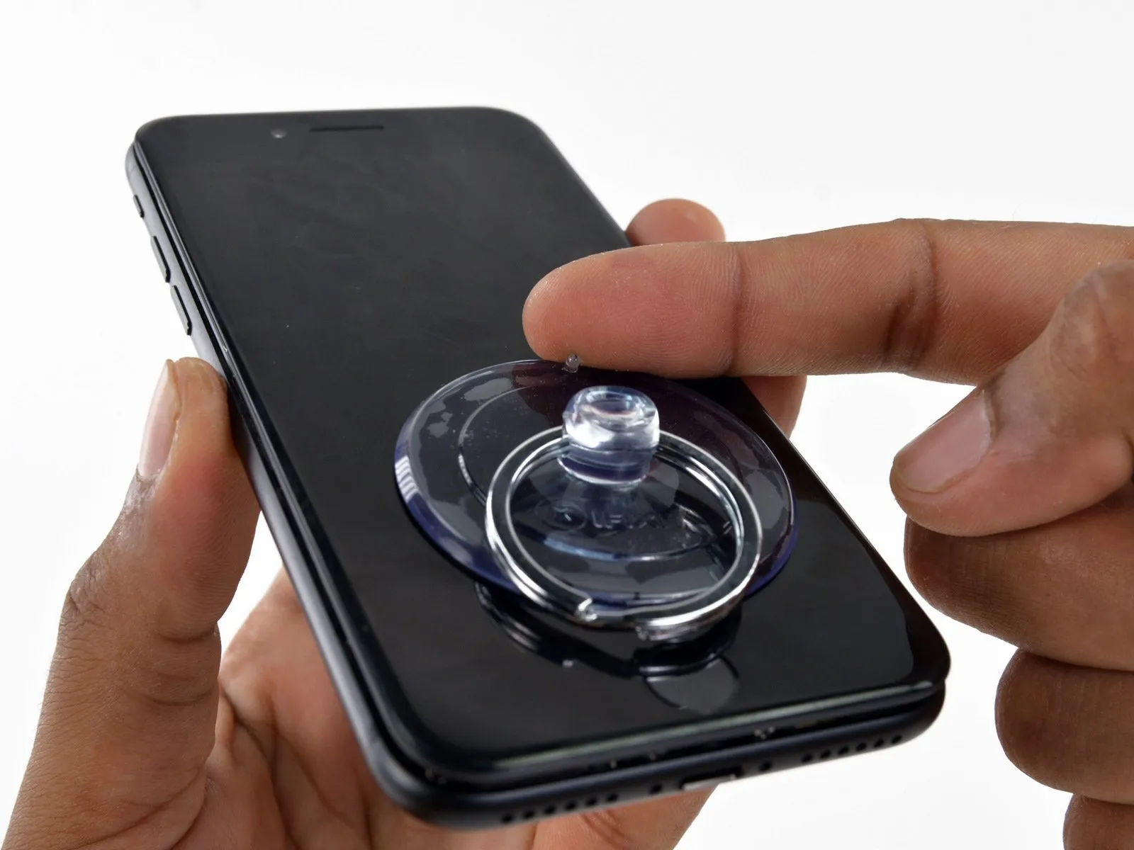
Using a suction cup, secure it to the lower portion of the display assembly, positioning it directly over the home button.
To guarantee a secure bond, position the suction cup so that it avoids covering the home button.
Using a suction cup, secure it to the lower portion of the display assembly, positioning it directly over the home button.
To guarantee a secure bond, position the suction cup so that it avoids covering the home button.
Step 13
Using a 5/32-inch hex key, carefully tighten the four M4 x 8mm screws securing the fan assembly to the heatsink, ensuring a torque of no more than 0.5 Nm to prevent damage.
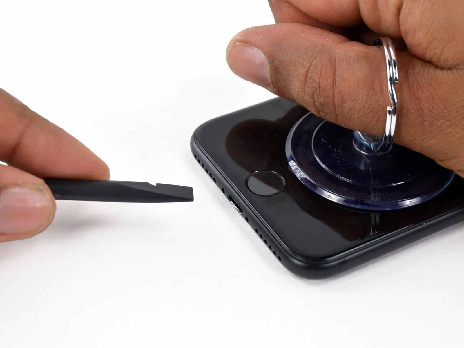
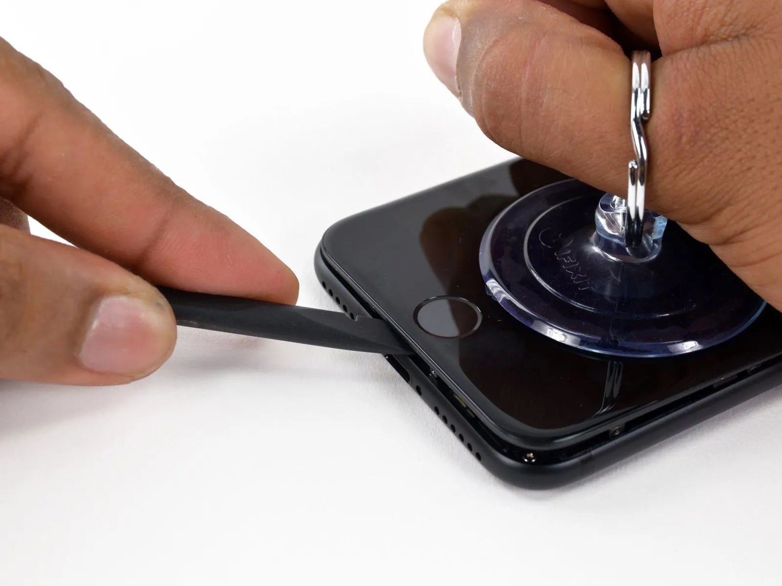
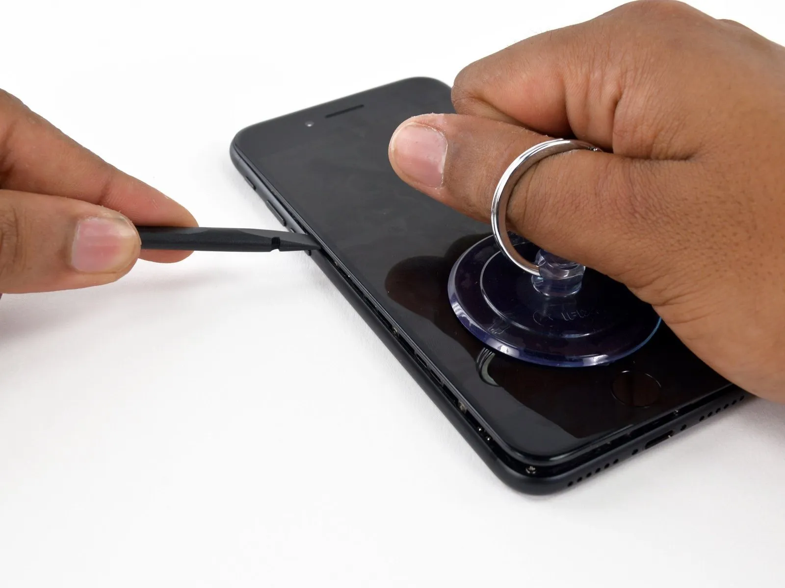
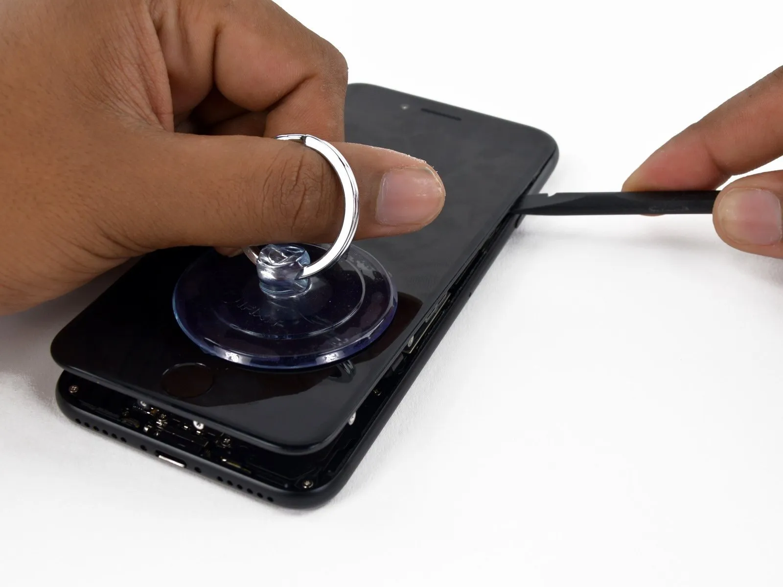
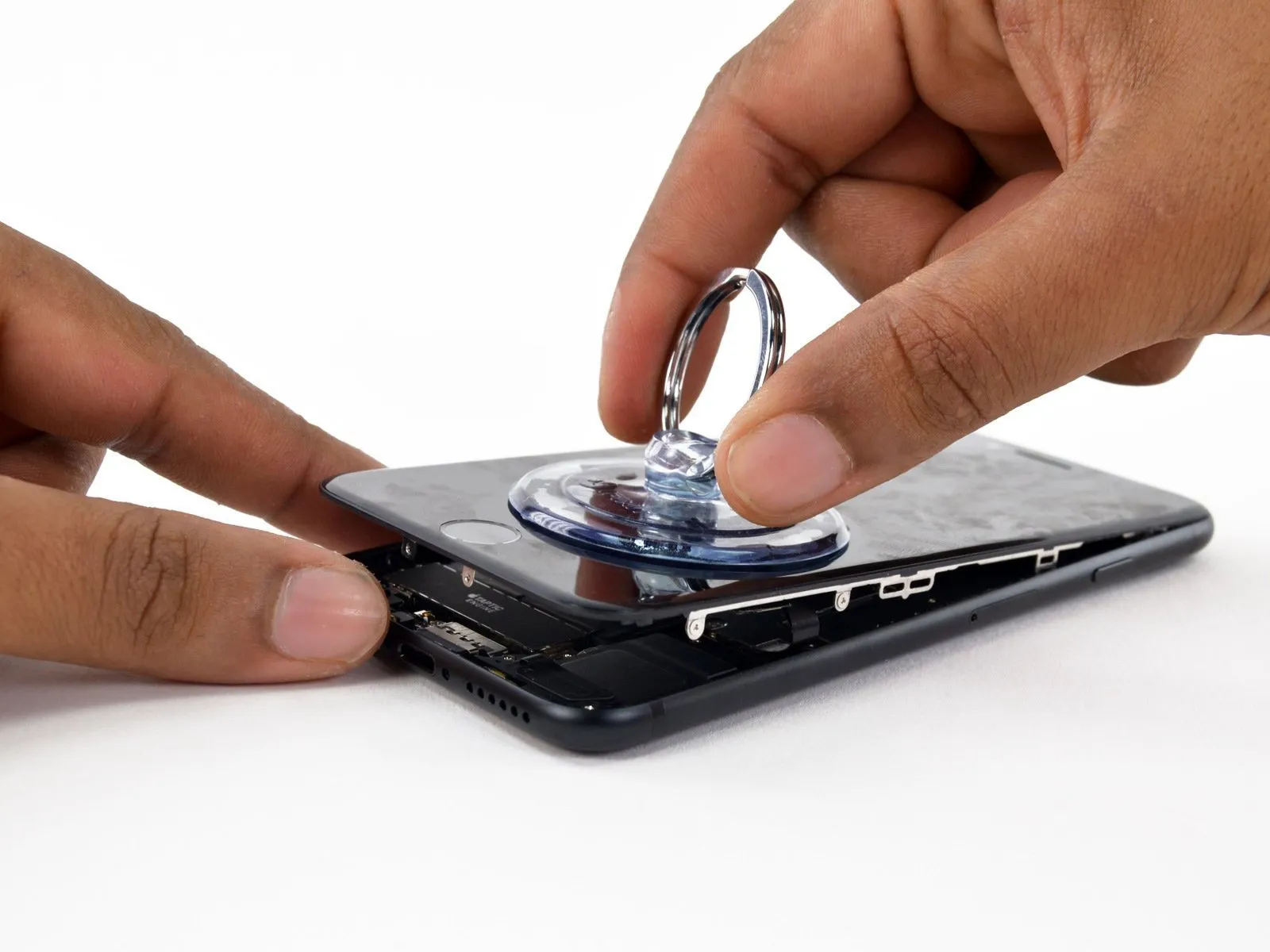
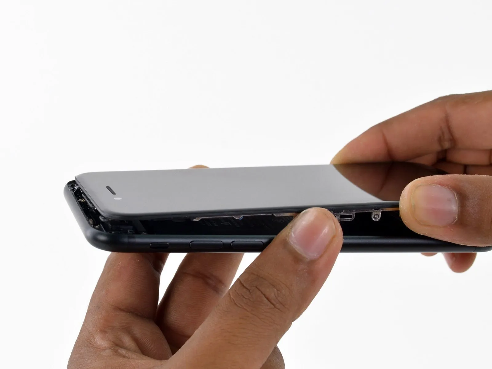
- Employ the suction cup to establish a slight separation between the display assembly and the back case.
- Because the display is sealed with a robust waterproof adhesive, separating it requires considerable pressure. Should you encounter resistance while attempting to create an initial opening, gently flex the screen in an up-and-down motion to reduce the adhesive's strength, allowing for spudger insertion.
Step 14
Carefully align the 4mm hex key to the retaining screw, ensuring it's fully seated, then rotate the screw counterclockwise until it disengages, taking care to avoid damaging the surrounding components.
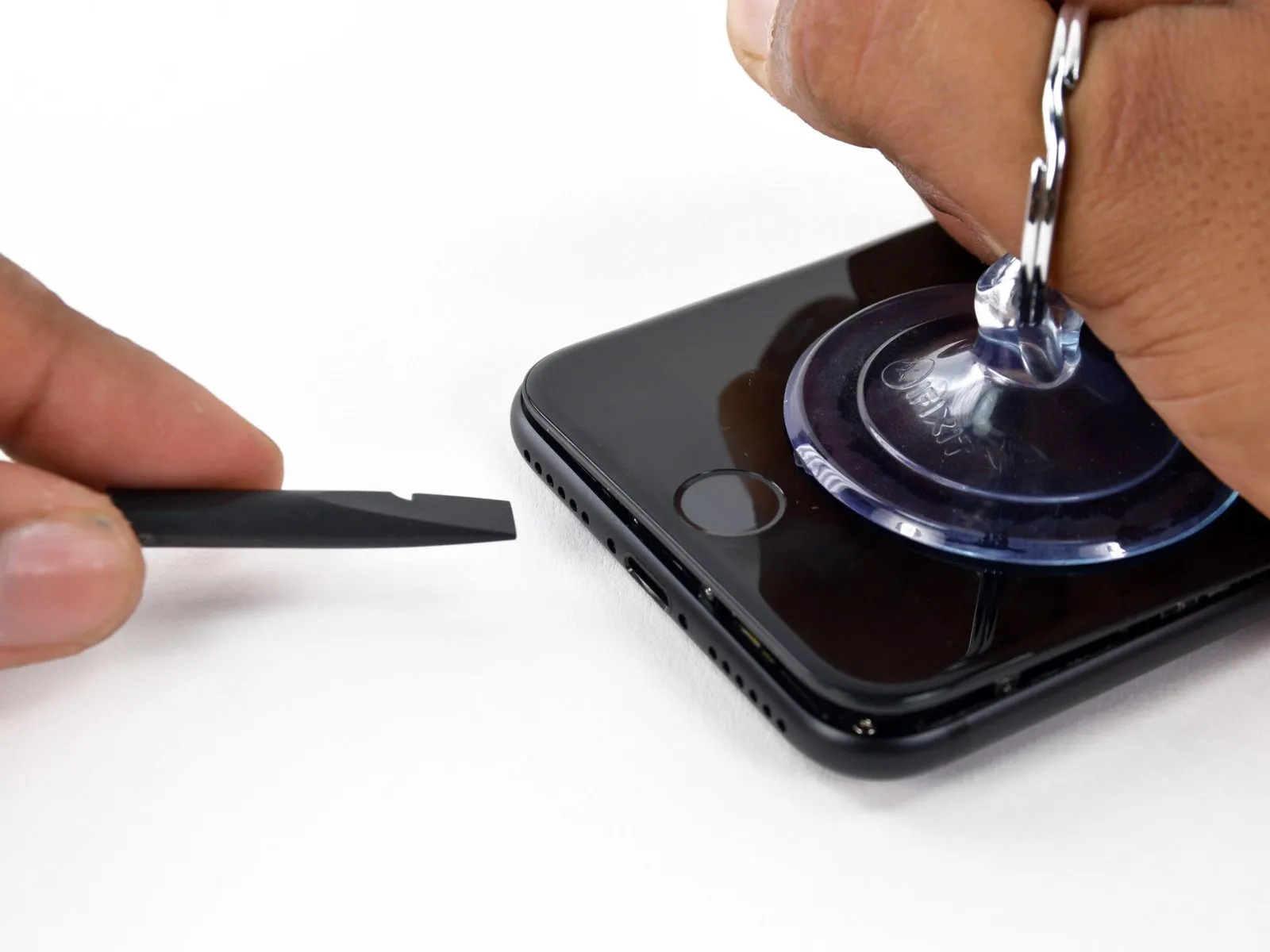
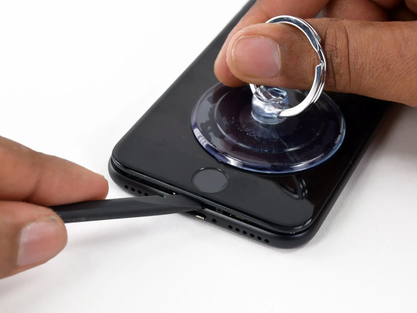
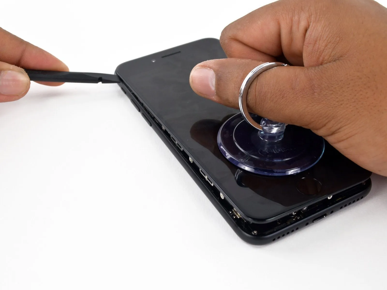
- Using a spudger, gently work it between the iPhone's casing and the internal components, starting at the lower edge.
- Using the spudger, gently increase the separation between the display assembly and the rear casing.
Step 15

Carefully align the 4mm hex key to the setscrew, ensuring it engages fully, then apply a torque of 1.5 Nm using the torque wrench to secure the motor shaft.
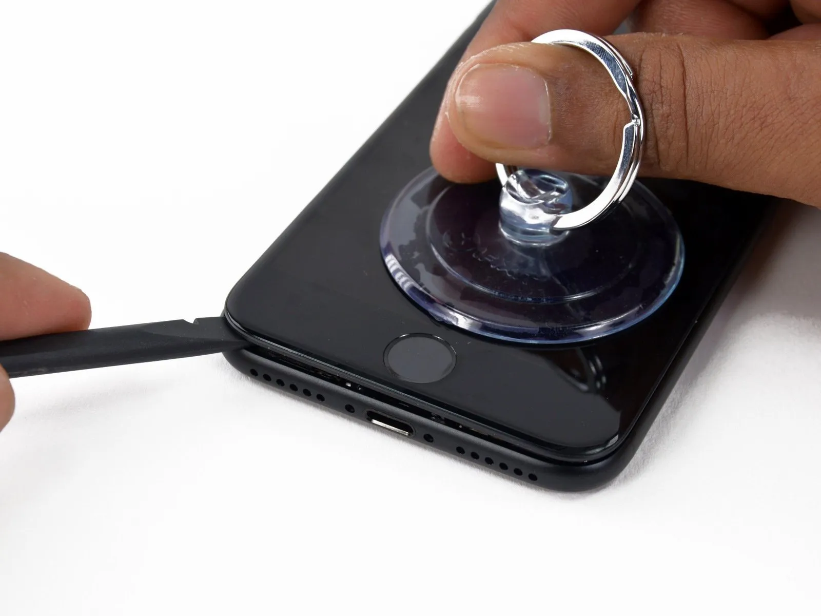
- Beginning at the lower edge, carefully insert a spudger between the iPhone's casing and its frame, progressing along the left side until the volume buttons and silent switch are reached.
- Do not attempt to separate the display's top portion from the rear housing, as it is secured with fragile plastic clips that could fracture.
Step 16
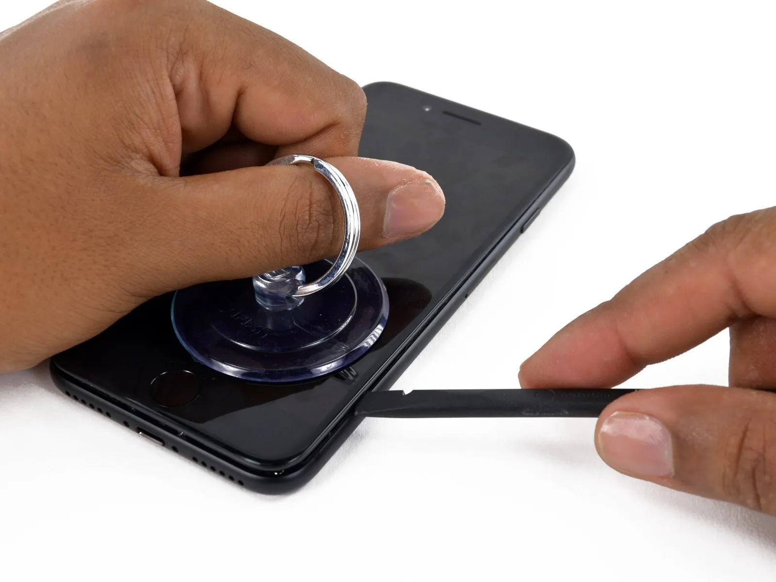
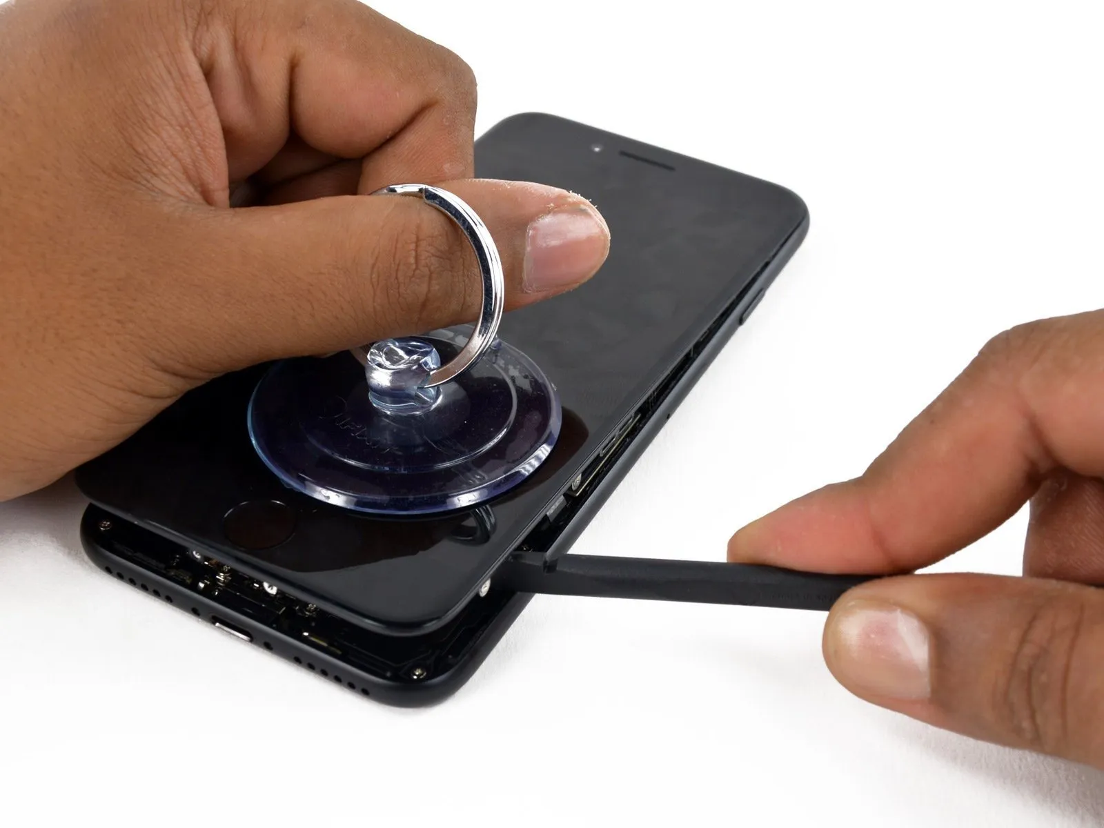
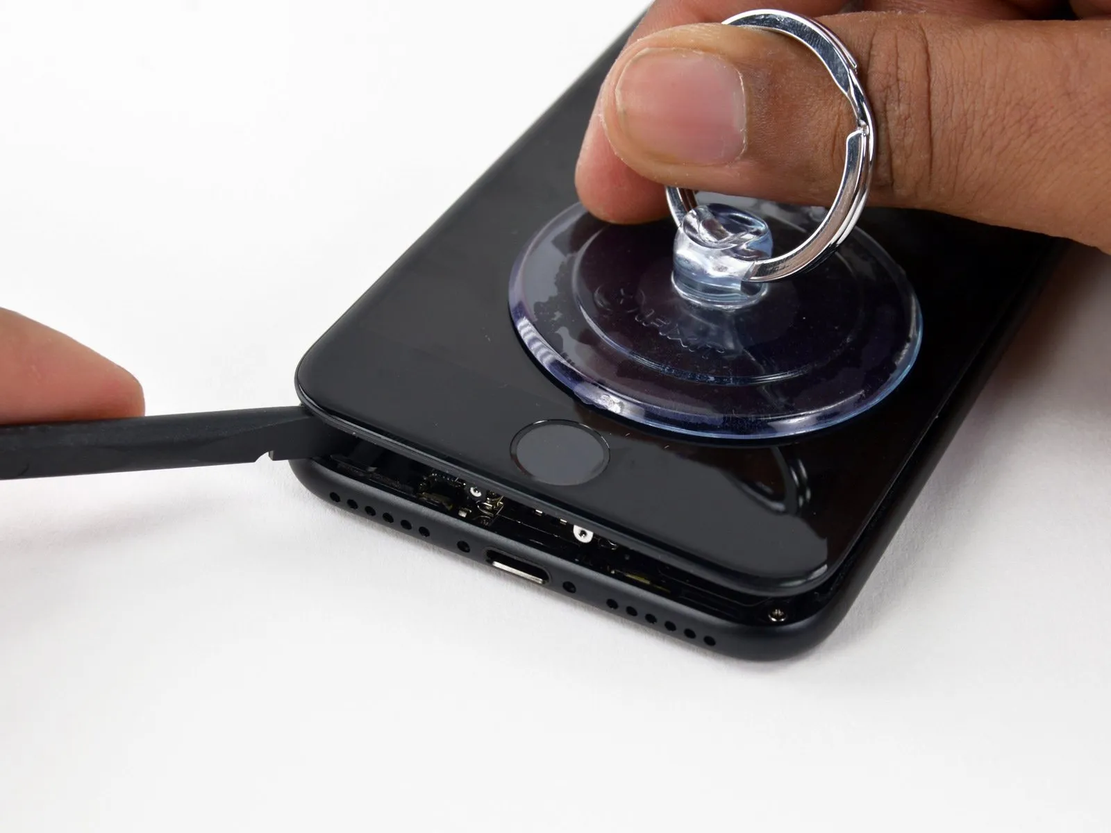
- Using a spudger, detach it from the left side of the iPhone, then slide the spudger's flat end into the lower right corner.
Using a twisting motion, increase the separation between the display assembly and the rear case with the spudger.
Using the spudger's flat edge, carefully separate the display from the phone body by releasing the adhesive bond along the right side.
Step 17

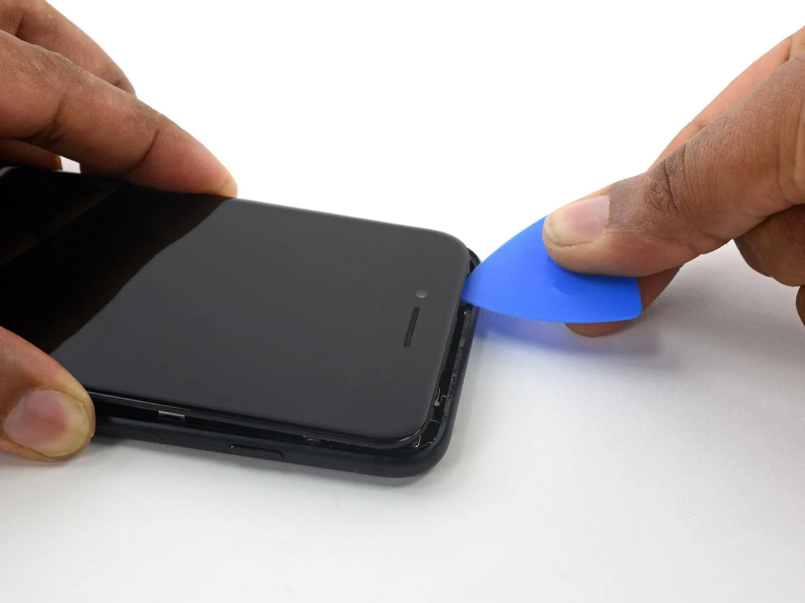
- Carefully raise the display by utilizing the suction cup.Using the iFixit opening pick, carefully separate the display assembly from the device body, beginning at the bottom edge, while applying gentle upward pressure to avoid damaging the adhesive securing the components..
Ensure the display remains level and does not tilt beyond its designated position.The angle should measure ten degrees.The right side of the device contains delicate ribbon cables that link the display assembly to the logic board.
Step 18
- To detach the tool, gently raise the small tab on the suction cup.
Step 19

- Carefully position the component by moving it laterally.Utilize a specialized opening tool.Carefully separate the rear cover from the display assembly along the iPhone’s upper edge to release the remaining adhesive securing the screen.
Step 20

- To release the screen from the rear casing, gently slide the display assembly outward, ensuring the retaining clips disengage.
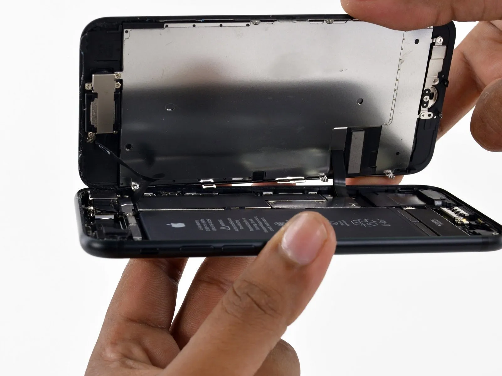
Carefully separate the display assembly from the device body by gently prying upward, initiating the separation from the right edge, mimicking the action of opening a book's cover.
Avoid fully detaching the display assembly at this point, as it contains delicate components.Flexible, multi-conductor electrical wiring bundles.Ensure the connection to the iPhone's main circuit board remains intact.
Position the device on a level surface, maintaining its open, book-like configuration.
Step 21 | Battery Disconnect
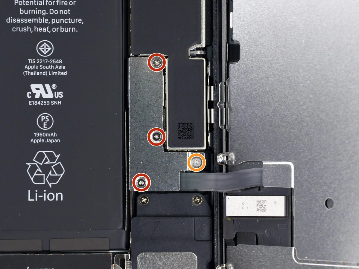
- Detach the listed components.Use a Y000 tri-wing screwdriver for this step.Remove the connector lower bracket.
- Three.Use fasteners with a diameter of 1.2 millimeters.
- Begin the process by executing step one.Use a screw with a diameter of 2.4 millimeters.
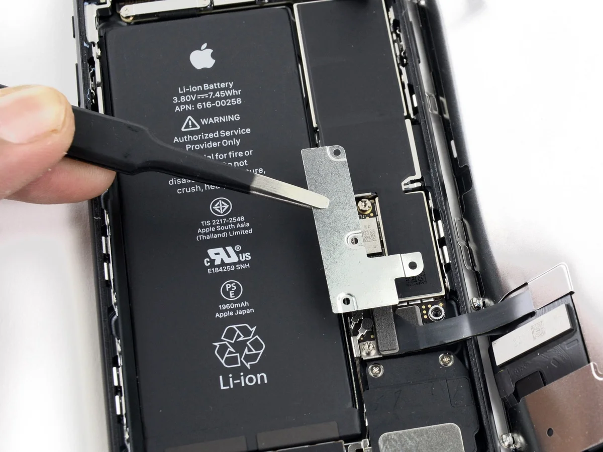
- Detach the lower bracket securing the connector.
Step 22

- Carefully detach the battery connector from its corresponding socket on the logic board by utilizing the tip of a spudger.
To avoid electrical connection and enable power-on, carefully flex the connector cable a small amount.
Step 23 | Display Group


- Carefully separate the two display connectors located at the bottom of the assembly by gently prying them upward, away from their sockets on the logic board, using the flat edge of a spudger or a fingernail.
Ensure a secure connection by applying pressure to each end of the cable until a distinct click confirms it’s fully seated within the block; avoid applying pressure along the cable’s length.
A slight misalignment of the connector can cause bending, which will result in irreversible damage.
Step 24


- Detach the pair of screws.Use a Phillips screwdriver with a 1.3 mm tip.Affix the bracket using the specified fasteners to the connector on the front panel sensor assembly.
Detach the bracket.
Step 25

- Carefully disconnect the front panel sensor assembly's connector from the socket located on the logic board.
To prevent deformation, reconnect the connector's ends individually.
Step 26

- Carefully detach the display assembly, ensuring all associated components remain undisturbed.
If you intend to substitute the perimeter display adhesive label during reassembly, pause the process at this stage.
Step 27 | Rear Camera

Employ the tool's flattened edge.Use a plastic pry tool to gently separate.Carefully separate the rear camera's pressure connector from its corresponding socket on the logic board.
Step 28
- Detach the listed components.Use a Phillips head screwdriver.Using a Phillips #0 screwdriver, tighten the three 3.5mm screws to 5.0 in-lb to affix the rear camera bracket to the camera module.
AUse a 1.3-millimeter screw.
AUse a 2.5-millimeter screw.
Step 29

- Detach the bracket.
Step 30

- Carefully detach the rear camera assembly.
Step 31

Using a 5/32-inch hex key, carefully tighten the four M4x8 screws securing the fan assembly to the heatsink, ensuring a torque of 4.5 in-lbs to prevent damage.
- Carefully detach the bracket, noting that its inner surface is likely bonded to the camera's lens ring via welding.
- Expect significant resistance during removal, and be aware that breakage is possible.
Step 32
Using a 5/32-inch hex key, carefully tighten the four M4x8 screws securing the fan assembly to the heat sink, ensuring a torque of 4 in-lbs is applied to each screw to prevent damage.Carefully remove the damaged lens as the final procedure.
Support the device with your hands to prevent flexing during application of pressure.
Maintain awareness of the device and your hand movements throughout the repair process.
- Select a suitable tool, ensuring it aligns with your comfort level and provides adequate leverage for the task.
- Apply firm, direct pressure with the selected tool against the lens until it releases from its position.
Support the device with your hands to prevent flexing during application of pressure.
Maintain awareness of the device and your hand movements throughout the repair process.