iPhone 7 LCD and Digitizer Replacement
Employing our repair kit and this streamlined procedure will simplify the complete screen replacement process for your iPhone.
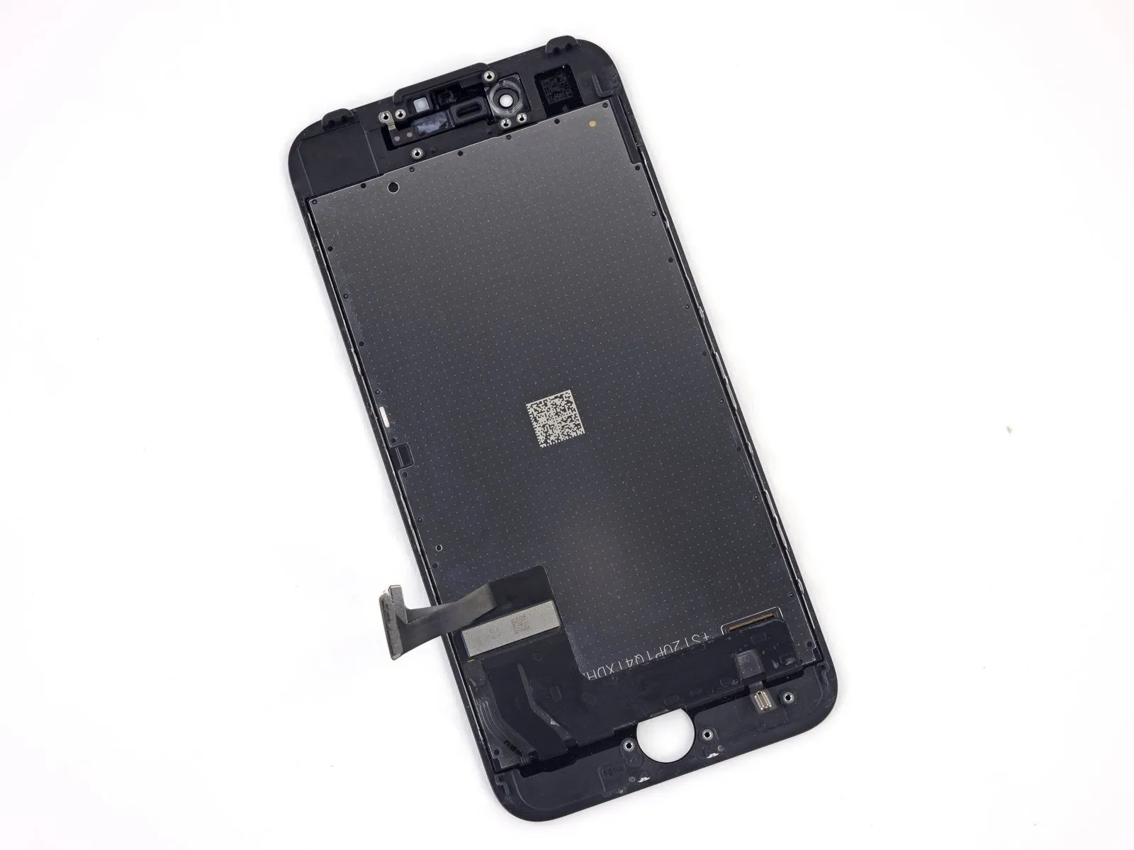
- Those with greater experience in repairs should proceed.To perform this repair, this guide focuses solely on replacing the iPhone 7’s LCD and digitizer assembly, often referred to as the bare front panel. The procedure necessitates moving several parts from the old screen to the replacement—specifically, the front camera assembly, earpiece speaker, LCD shield plate, and the home button/Touch ID sensor—before final installation.
During screen or display replacements, meticulously move the existing ribbon cable connector and its attached securing hardware to the new panel, ensuring precise alignment and secure fastening.Locate the Touch ID sensor within the device's home assembly.The new display requires connection to function correctly; Apple pre-pairs the solid state home button to its corresponding logic board, and separation during replacement will prevent its operation.
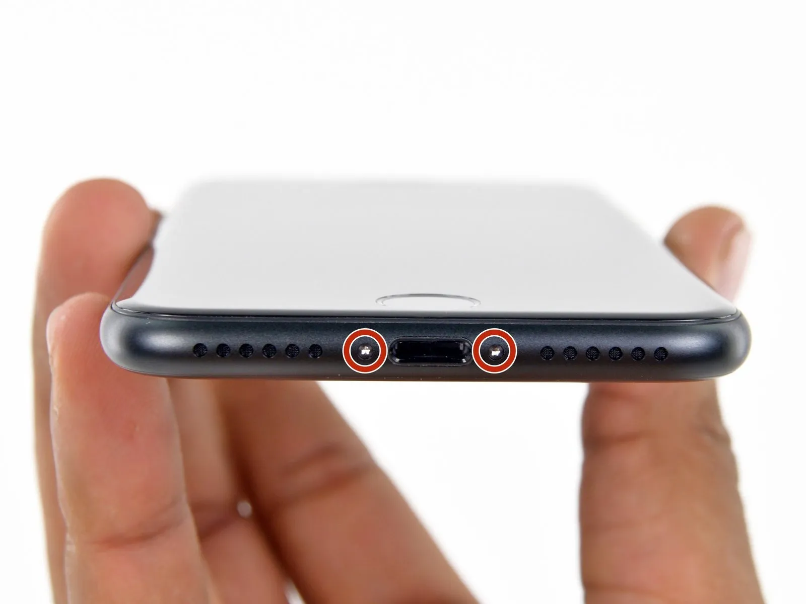
Step 1 | Pentalobe Screws
- To ensure optimal performance during the repair process, fully deplete the iPhone's battery until it registers as having less than 25% remaining.Ensure the battery is fully charged.Accidental puncture presents a fire and/or explosion hazard.
- To prevent electrical shock or damage, ensure the iPhone is completely de-energized prior to commencing the repair process.
- Using appropriate tools, detach the two screws measuring 3.4 mm in diameter and featuring a pentalobe head, located along the iPhone's lower border.
- Removing the display assembly will damage the iPhone's water resistance; ensure replacement seals are available for installation prior to proceeding, or exercise extreme caution to prevent liquid ingress during reassembly if the original seals are reused.
Step 2 | Mark your opening picks


- To avoid potential damage to your device, ensure the opening pick does not extend beyond a safe depth; use this step to create a reference mark on the pick, limiting its insertion.
- Determine the dimension using an appropriate measuring tool.Three millimeters.Using a permanent marker, clearly indicate the opening point on the pick.
- Alternative corner markings, using the same measurement tools, can be applied to the remaining corners of the pick.
- Securely affix a coin to the tip of a pick using adhesive tape.Three millimeters.Beginning at the foremost point.
Step 3 | Tape over the display


- To avoid injury and contain shattered fragments while you work, secure the cracked display glass with tape.
- Apply strips of transparent packing tape across the iPhone screen, ensuring complete coverage by layering them until the entire display surface is protected.
- To prevent glass fragments from scattering and maintain stability during the display separation process, ensure this step is performed carefully.
- To safeguard your eyes from potential glass fragments released during the repair process, always use safety glasses.
- Should suction cup adhesion be compromised by shattered glass during subsequent procedures, a robust tape—like duct tape—can be folded to create a lifting grip for the display.
Step 4 | Anti-Clamp instructions


- To simplify the opening process, the following three steps detail the use of the Anti-Clamp tool, a device specifically created for this purpose; if you choose not to utilize the Anti-Clamp, proceed to the instructions three steps further down.
- Refer to the included guide for detailed procedures regarding Anti-Clamp operation.
- Grasp and extract theEmploy the provided blue-colored handle.To release the Anti-Clamp's arms, rotate them in a reverse direction.
- Position the arms so they extend across the iPhone's left or right side.
- Affix two suction cups, one to the front and one to the rear of the iPhone, placing them close to the lower edge, directly over the home button.
- Apply vacuum by pressing the cups firmly against the surface needing treatment.
- To improve the Anti-Clamp's grip if the iPhone's exterior feels excessively smooth, apply adhesive tape to the device's surface.
Step 5


- Grasp and draw the component outward.The component is identified by a blue handle.Advance the mechanism to engage the locking arms.
- Rotate theGrasp firmly.Rotate the component a full revolution, ensuring it turns consistently until you observe the edges of the receptacles expanding.
- Verify that theEmploy vacuum-based fasteners to secure components.Ensure the arms stay properly positioned relative to one another; should misalignment occur, gently release the suction cups a bit and then reposition the arms.
Step 6


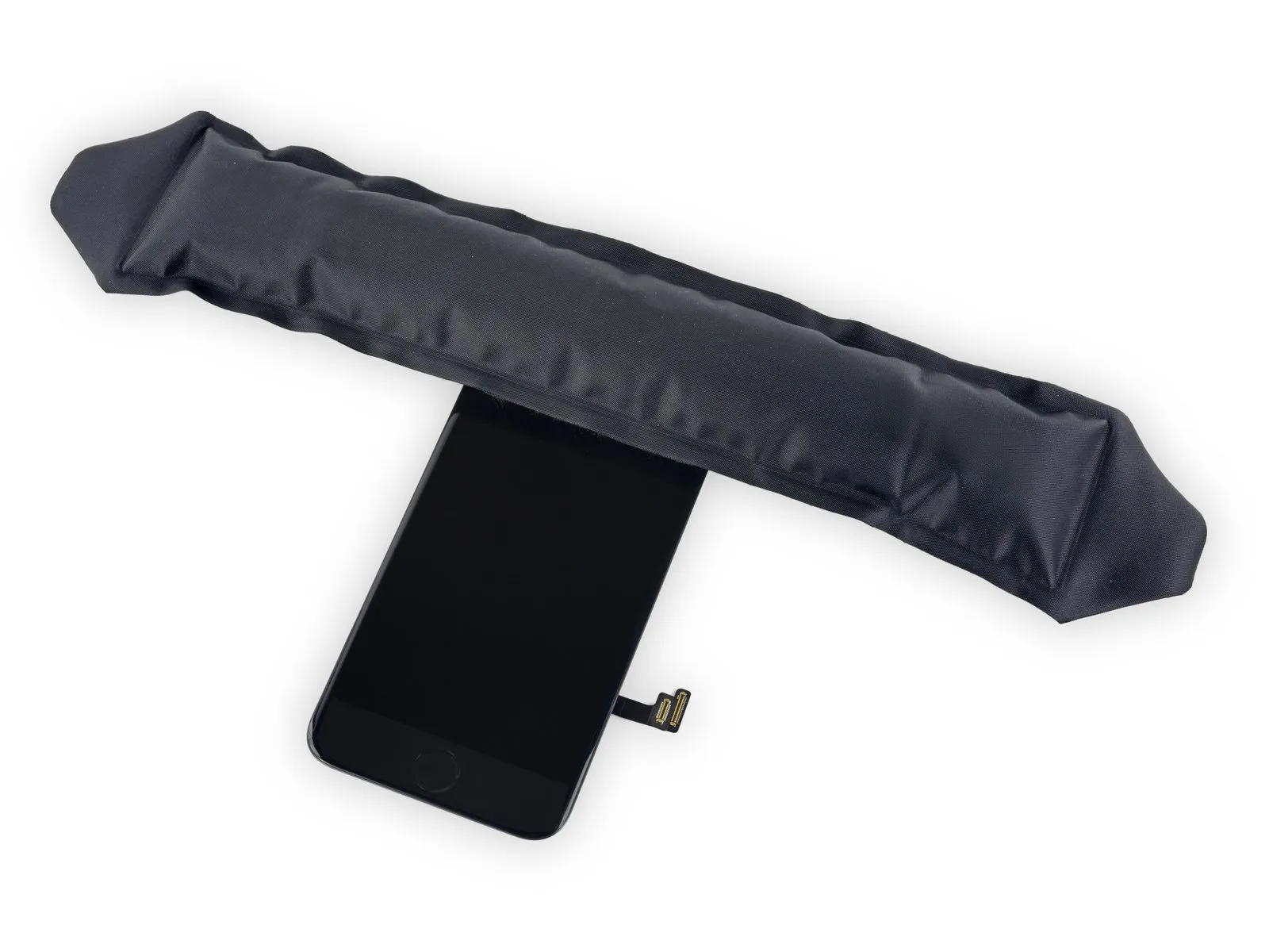
- Apply warmth to a component using a heat source.Use the iOpener.Carefully guide the thread through the Anti-Clamp’s arms; alternatively, apply warmth using a hair dryer, heat gun, or hot plate, exercising caution as excessive heat may harm the display and/or internal battery.
- Carefully bend theUse the iOpener to gently warm the adhesive securing the display assembly.Position the component flush against the lower edge of the iPhone's casing.
Allow a full 60 seconds for the adhesive to soften and create a separation. - Carefully position the component into its designated space.Use a specialized tool designed for prying, often referred to as an opening pick.Carefully slide the component into the designated space.
- To ensure adequate separation, increase the heat applied to the component and then rotate the handle 90 degrees.
Allow the Anti-Clamp device to function for a full minute after each incremental tightening of no more than 90 degrees. - Proceed directly to the sequence of instructions following these three, bypassing them entirely.
Step 7 | Heat the display
Employing a suction cup and plastic opening tool, carefully detach the screen assembly, following the procedure detailed in the subsequent three instructions.Employ a vacuum-forming device to create a secure hold, ensuring the resulting adhesion reaches a minimum pressure of 25 PSI and utilizes a rubber compound with a Shore A hardness of 70 to prevent damage to the surrounding surfaces..
Applying heat to the phone's bottom perimeter with a heat gun or hairdryer will loosen the adhesive that holds the display in place, simplifying the opening process.
Apply heat from a hairdryer, or a similar device, to loosen the adhesive bond before proceeding.Use the iOpener.Maintain contact with the phone's bottom edge for approximately 90 seconds.
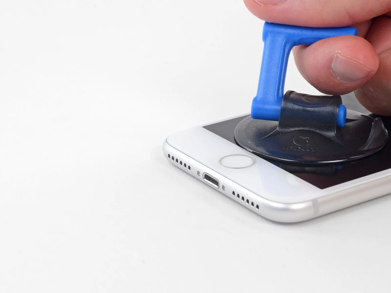
Step 8 | Separate the display
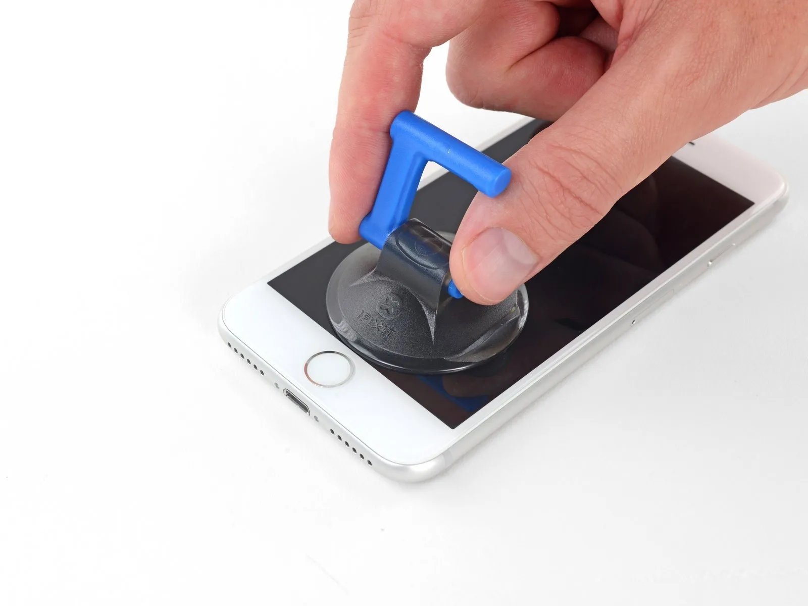

Use a brush to spread a thin, even layer of the specified adhesive, ensuring complete coverage of the 1-square-inch area, and allow it to cure for the recommended 30 minutes before proceeding, observing all safety precautions regarding ventilation and skin contact.Employ a vacuum-forming device to create a secure hold using the provided adhesive-backed disc.Position the component on the lower section of the front panel, directly above the home button.
To ensure a proper seal between the suction cup and the front glass, avoid positioning the cup so that it covers the home button.
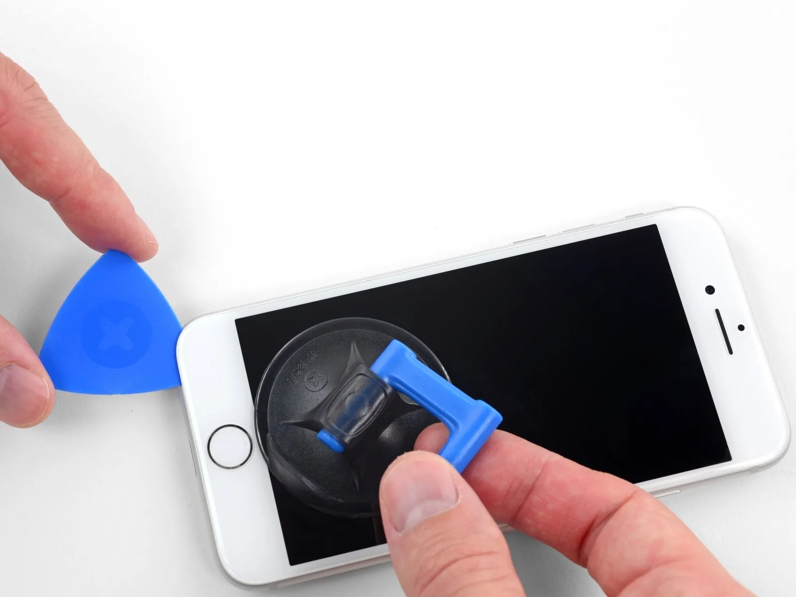
Step 9


Apply steady, even force to lift the suction cup, generating a small separation between the display assembly and the device's surrounding frame.
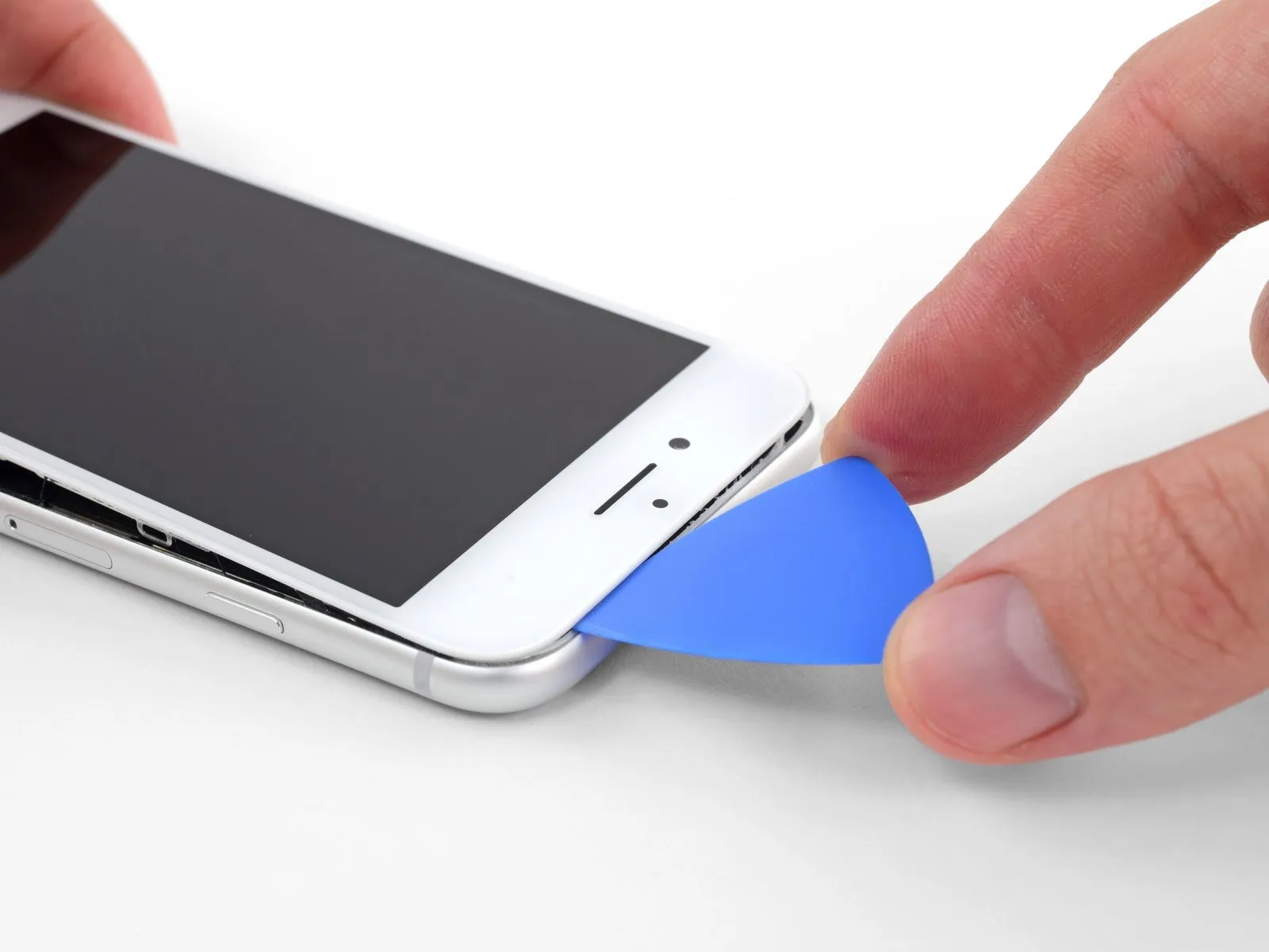
- Using a specialized opening tool, carefully introduce its tip into the separation.
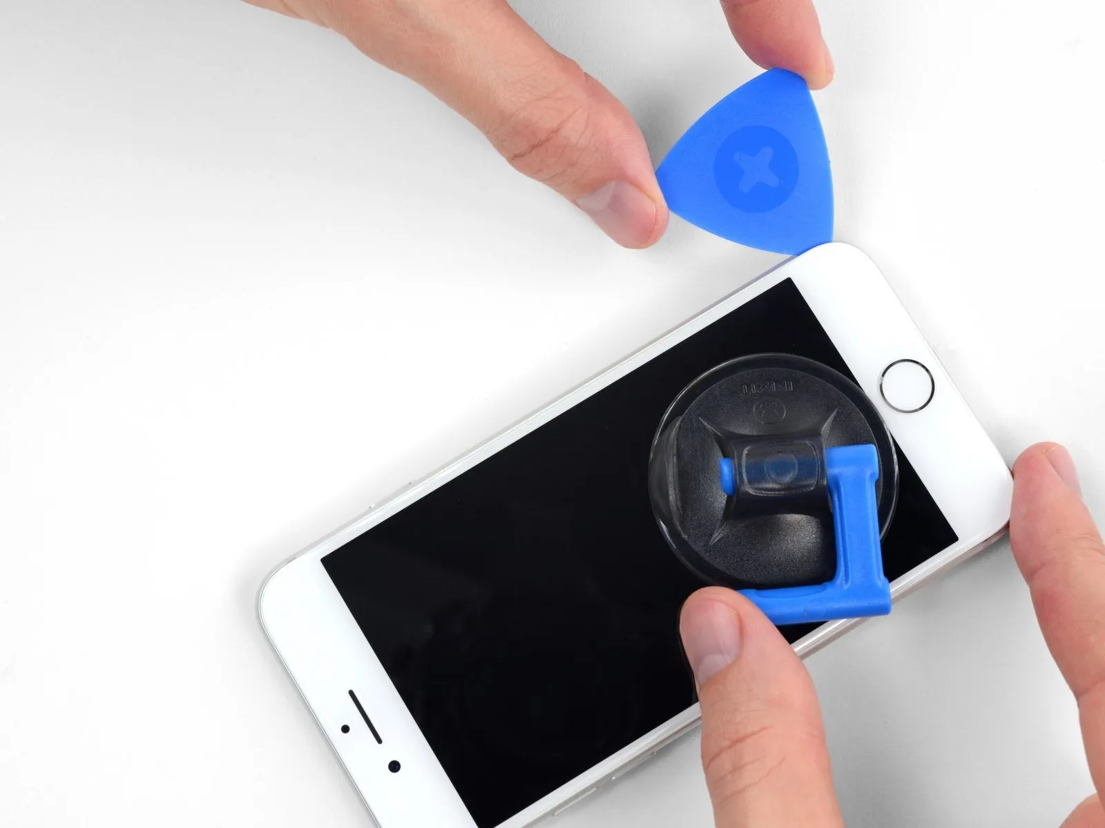
Step 10


- Beginning at the bottom edge, insert the opening pick between the display and the phone’s left side, progressing upwards towards the volume buttons and silent switch to carefully separate the adhesive securing the display.
- Position yourself close to the upper left edge of the screen.
- Avoid forcing separation between the display's upper border and the back cover; delicate plastic fasteners secure them, and breakage is possible.
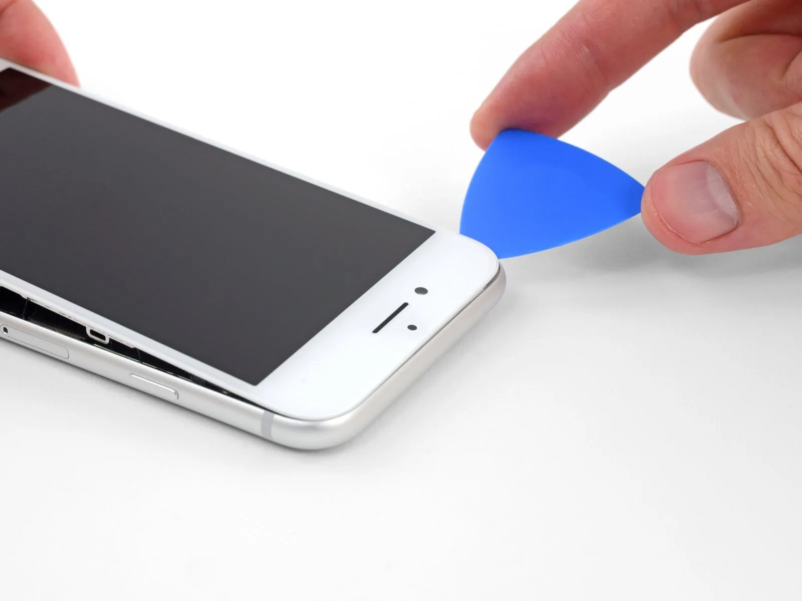
Step 11 | Screen information

Avoid placing your opening tool along the iPhone's right side, as this area contains fragile wiring that could be harmed.
Step 12


Using your tool, begin at the lower-right edge of the iPhone and move it along the perimeter, releasing the adhesive by sliding it along the corner and up the right side.
- To prevent damage to the display cables, limit the insertion depth of the pick to a maximum of 3 mm.
Step 13


- Using a gentle upward motion, disengage the display from its housing by lifting the lower perimeter with the suction cup.
- The display's upward angle should be limited to a maximum of.Set the temperature dial to 150 degrees.Careless handling could damage the display's ribbon cables, potentially causing them to stretch or rip.
- To detach the suction cup, grasp the small projection located on its surface and apply traction.
Step 14

Step 15


Step 16


- Using a prying tool, carefully lift the display assembly upwards, initiating the separation from the rear housing along the left edge, mirroring the action of opening a book's cover.
- Before completely disconnecting the display, be aware that multiple delicate ribbon cables, which remain connected to the iPhone’s logic board, are still in place.
- To allow hands-free access during the repair process, temporarily support the display using an external object.
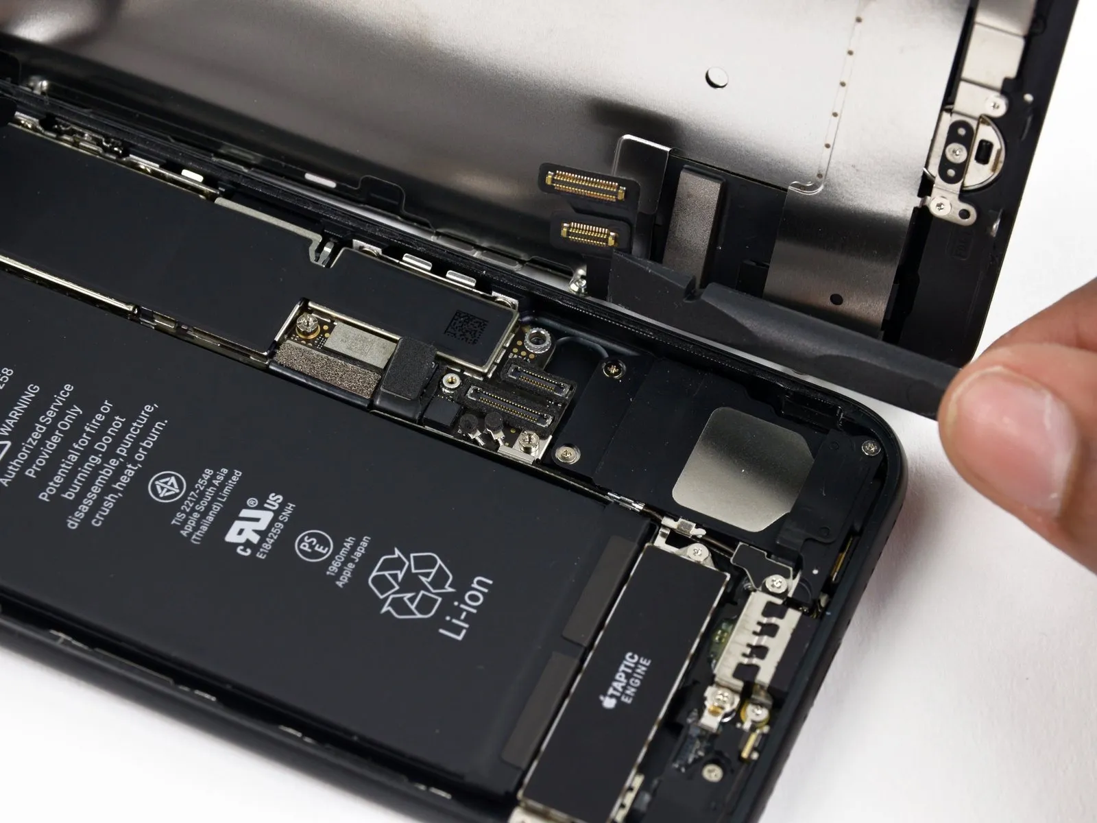
Step 17 | Battery Disconnection
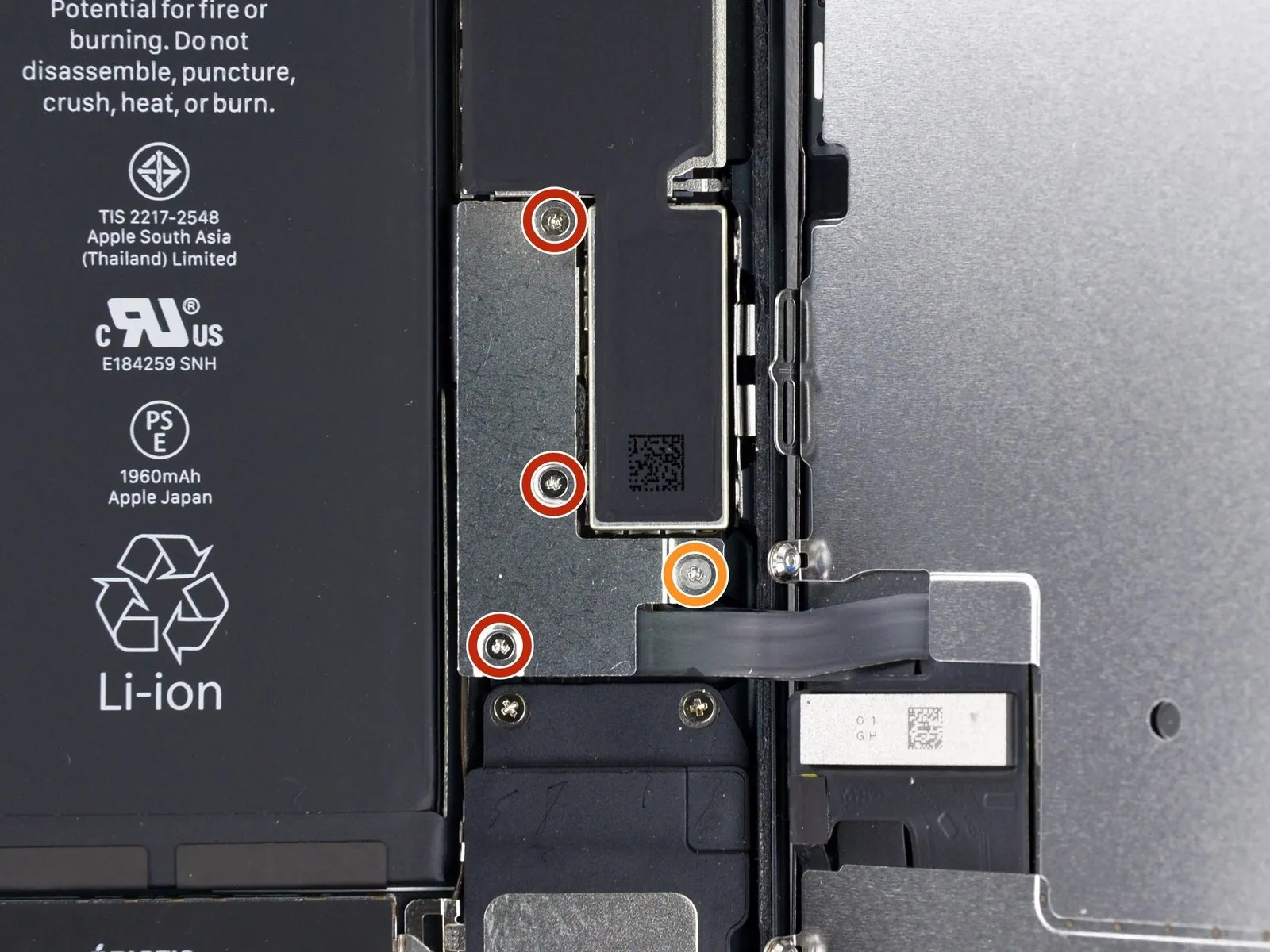
- Using a tri-point screwdriver, detach the four screws.Using a 3mm hex key, carefully tighten the screw to a torque of 5 Nm, ensuring that the retaining clip remains properly seated and avoiding damage to the threaded insert.Use screws with these lengths to fasten the lower connector bracket:
Use three fasteners with a 1.2-millimeter diameter.Secure with screws.
Use a 2.4-millimeter tool.Fasten with a screw.
To prevent damage to your iPhone during this repair, carefully organize all screws, noting their original locations for correct reassembly.
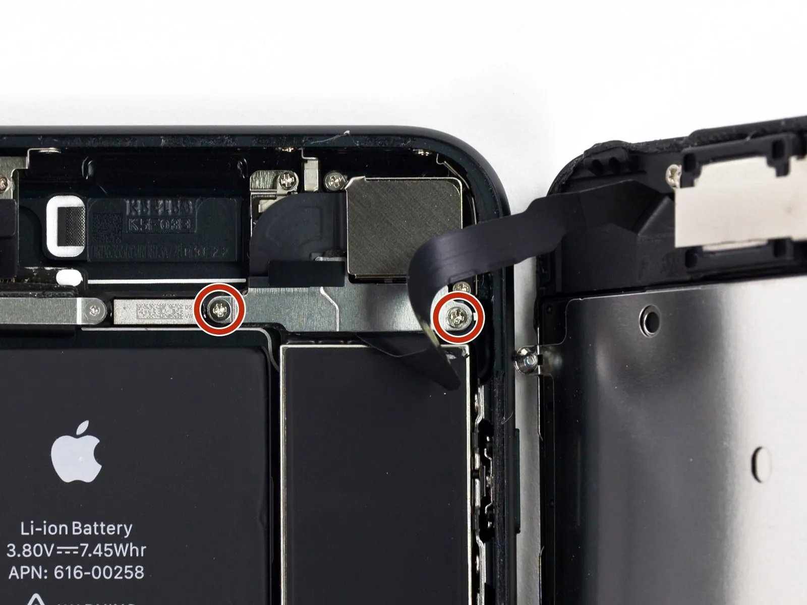
Step 18
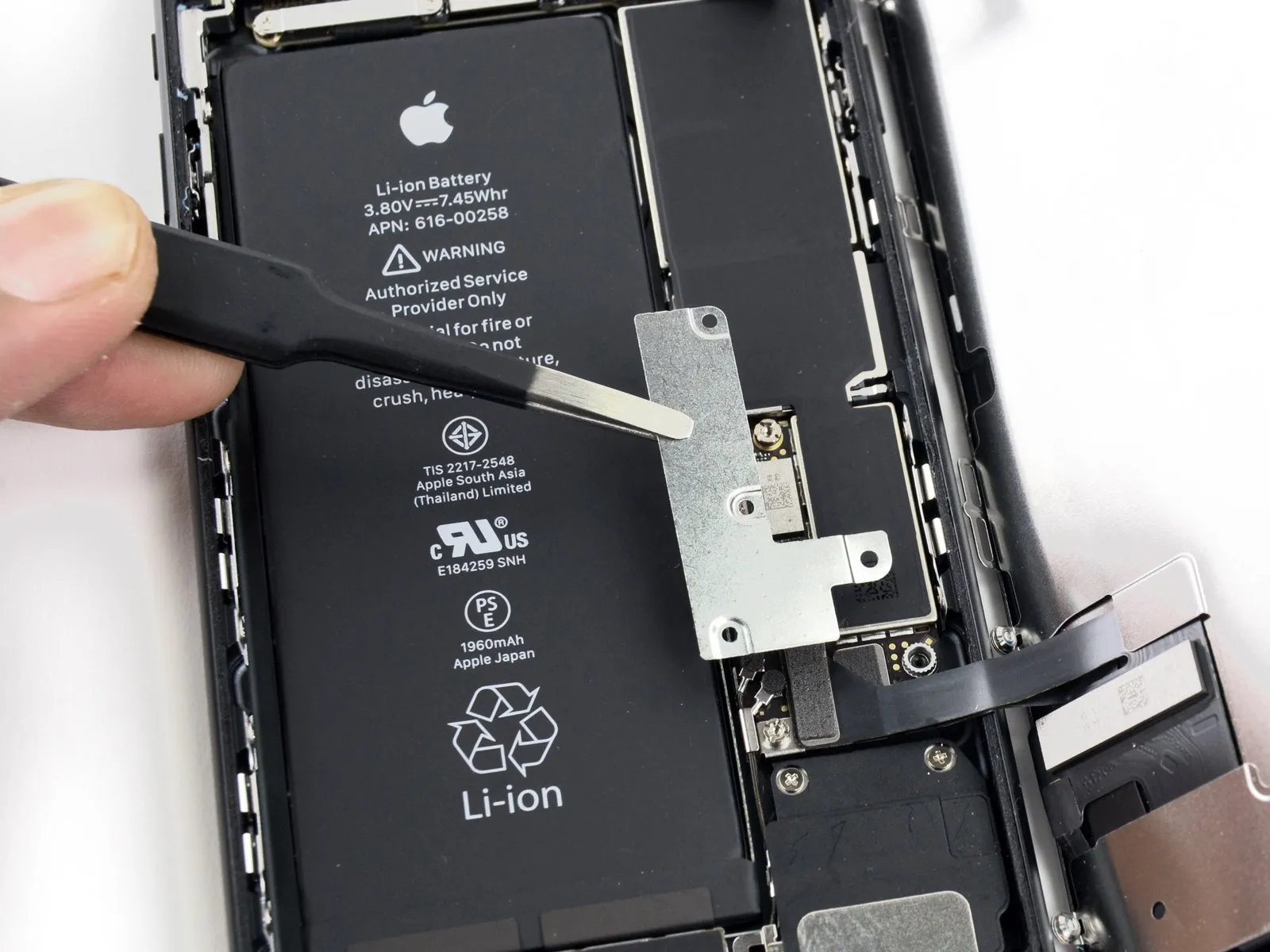
Detach the bracket securing the lower connector.
Step 19
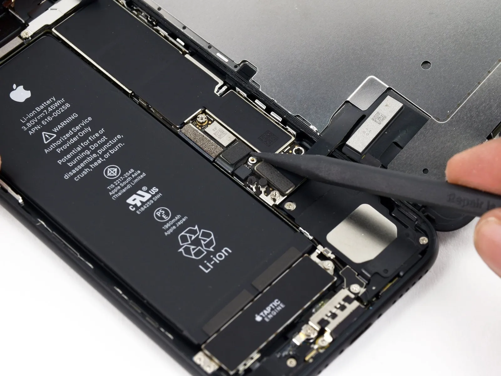
Carefully insert the tip of a screwdriver to actuate the retaining clip.Use a plastic pry tool to gently separate.Carefully disengage the battery connector from its receptacle on the logic board.
To avoid accidental power delivery to the device, gently elevate the connector cable.
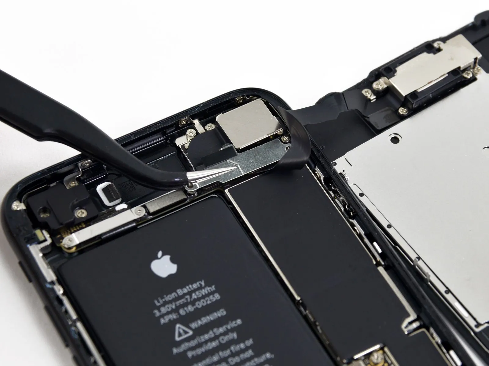
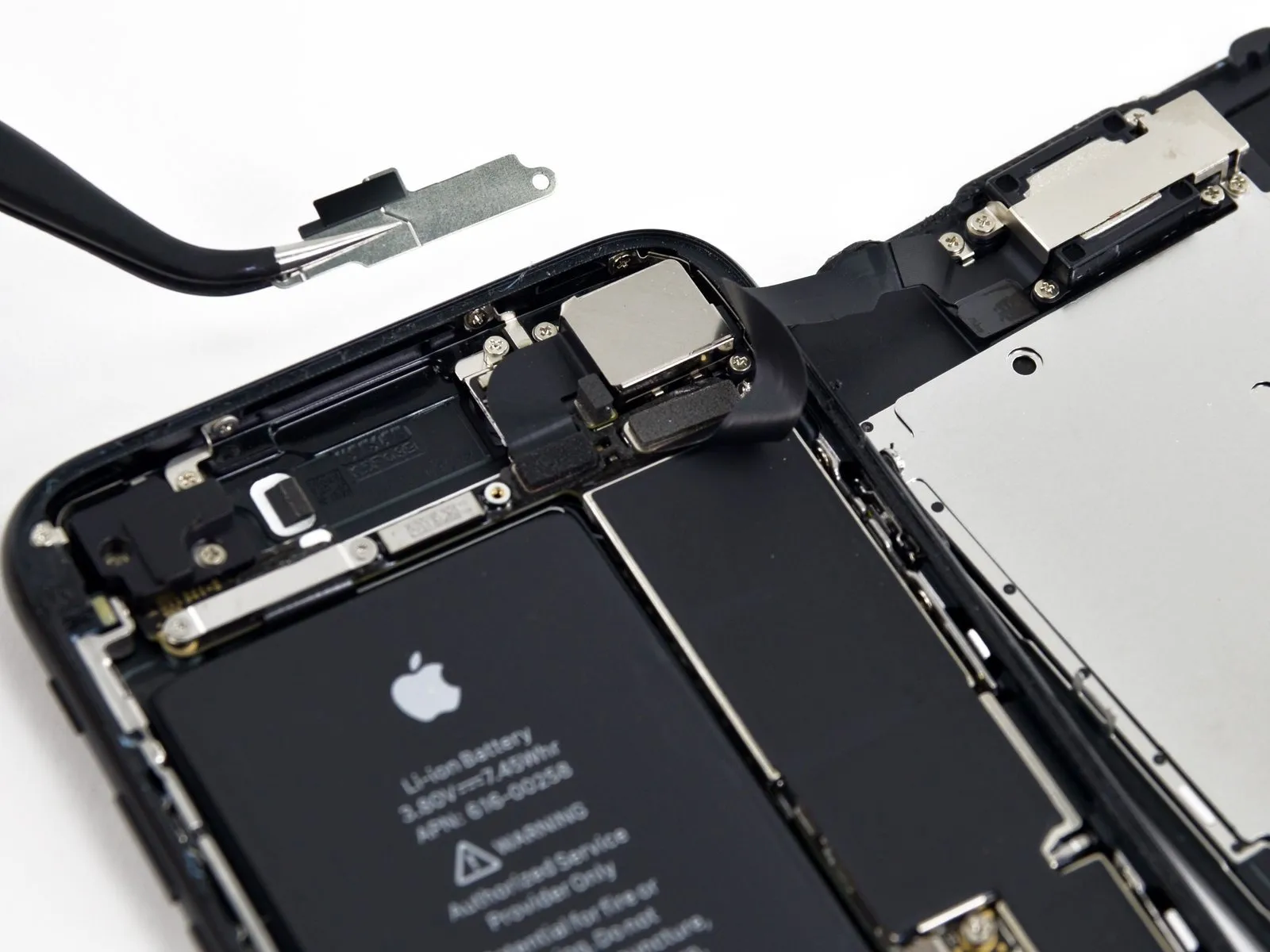
Step 20 | Display Assembly
Prior to either detaching or attaching the cables in this procedure, ensure the battery's power is completely isolated.
Employ a 3/8-inch socket wrench to securely tighten the fastener to a torque of 15 Nm, ensuring caution is exercised to prevent damage to the retaining clip.Use a plastic pry tool, often referred to as a spudger.Use a fingernail or similar tool to carefully lift the two lower display connectors vertically away from their sockets on the logic board, ensuring disconnection.
Ensure each connector end is fully seated by applying even pressure until a distinct click is heard, then repeat the process for the other end; avoid applying pressure to the connector body itself, as even minor misalignment can result in bending and irreversible damage.
Following reassembly, a non-functional display—characterized by a blank screen, white lines, or unresponsive or limited touch functionality—may be resolved by disengaging and then meticulously reseating both display cables, ensuring a secure connection.
Step 21
- Detach the pair of fasteners.Use a Phillips head screwdriver, size #000, with a tip measuring 1.3 millimeters.Use the specified screws to fasten the bracket, ensuring it covers the connector for the front panel sensor assembly.
- Certain phone models may incorporate a Y000 component, which Apple introduced during the product's operational lifespan.
Step 22
- Carefully detach the connector linking the front panel sensor assembly to its socket on the logic board.
- To reduce the chance of deformation, reconnect the press connector by attaching one end at a time.
Step 23
- Carefully detach the display assembly, ensuring all connections are released.
- If you intend to substitute fresh adhesive along the display's perimeter during reassembly, stop at this point.
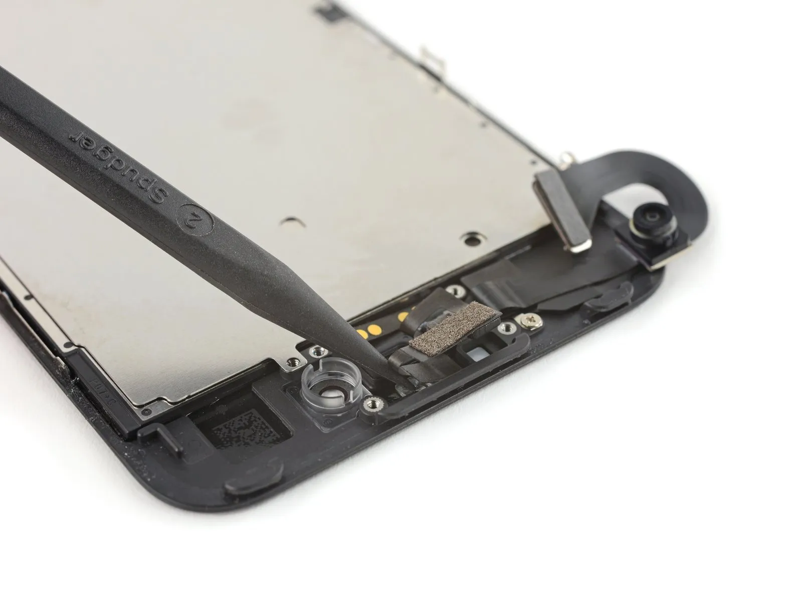
Step 24 | Home/Touch ID Sensor

- Using the appropriate size screwdriver, detach the four screws.Using a 3mm hex key, carefully tighten the screw to a torque of 5 Nm, ensuring you observe the warning regarding potential damage to the retaining clip.Use screws to fasten the bracket directly above the home and Touch ID sensor.
- Begin the process by executing the action designated as "one."A screw with a diameter of 1.1 millimeters.
- A quantity of three is required.Use screws with a diameter of 1.3 millimeters.
- To prevent home button failure during reassembly, ensure these screws are tightened appropriately, avoiding excessive force.
Step 25

Step 26


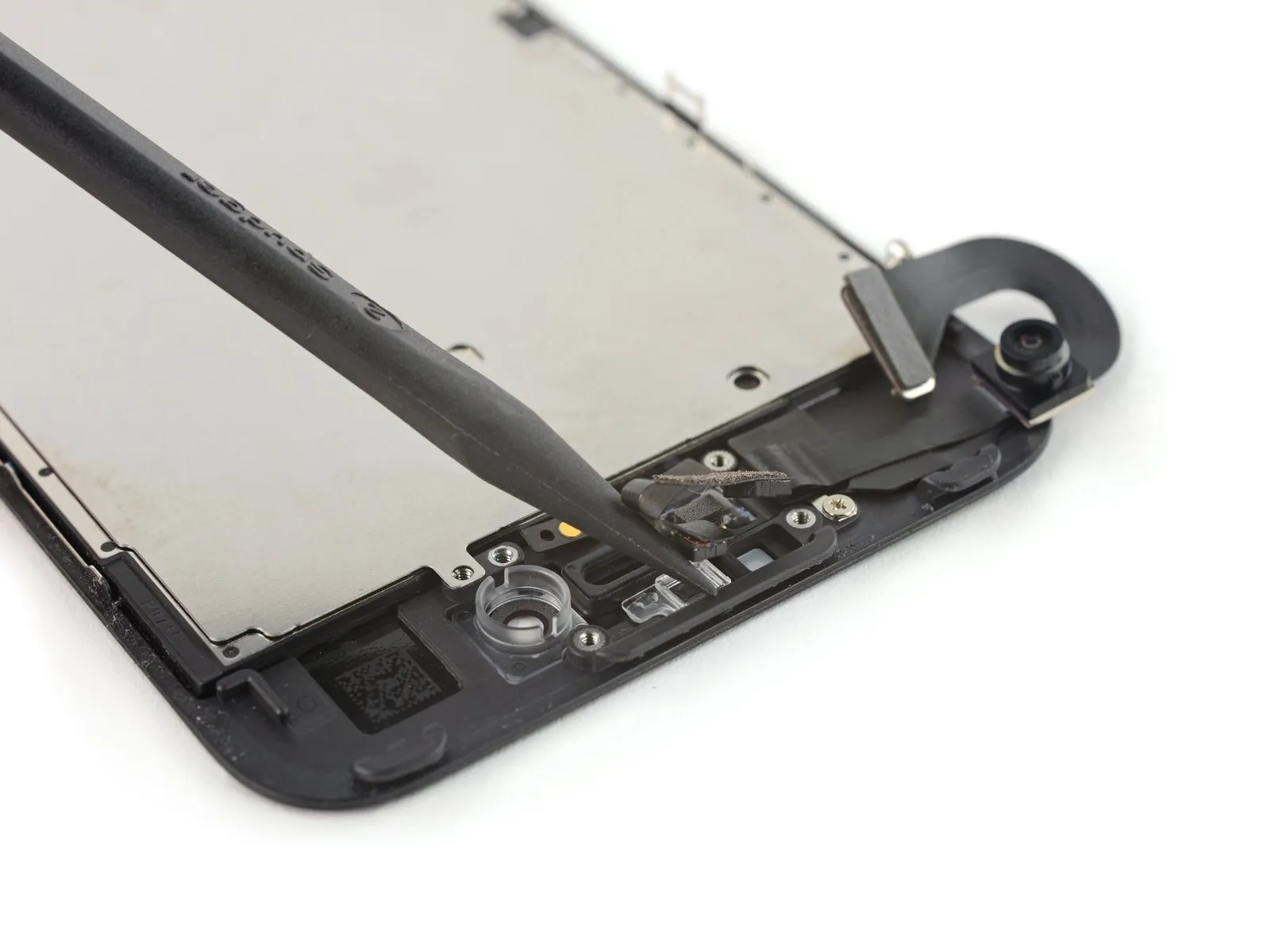
- Using a prying tool, carefully release the home button cable connector from its socket by gently separating it from underneath the left side.
- To prevent the connector from lifting completely, apply downward pressure on the cable's upper surface using the broad, flat edge of your spudger, and at the same time, gently lift the connector's left side. Exercise extreme caution to avoid harming the cable or connector, as damage will render the sensor inoperable.
Step 27


- Gently use a prying tool to release the connector from its position, then shift it aside to allow access to the home/Touch ID cable.
- Exercise extreme caution during this procedure, as damage to the iPhone is likely if you proceed hastily or apply force incorrectly. Use the prying tool deliberately to avoid harming the Touch ID components; irreparable damage requiring replacement by Apple is a potential consequence.
- To release a connector that resists separation, apply warmth with a hair dryer or iOpener to loosen the adhesive bond, then attempt disconnection once more.
- Avoid fully disconnecting the connector; instead, gently raise it a small amount to allow removal of the home/Touch ID sensor cable located beneath it.
Step 28

To facilitate safe removal, gently warm the region surrounding the home button and Touch ID sensor, which will reduce the adhesive securing the cable.
To release the adhesive securing the display, turn it face down and apply heat to its bottom edge; use a hairdryer or iOpener, maintaining the heat for approximately 90 seconds to soften the adhesive.
Step 29


Step 30

- Carefully detach the home/Touch ID sensor assembly from the display by gently prying it upwards from the front surface.
- Before reassembly, route the cable through the aperture located on the display's front surface.
- To facilitate reattachment of the home button bracket, discard the additional Y000 screw, which might be pre-installed on the right side of the Home Button on your new component.
- This procedure details how to apply new adhesive strips to secure the screen.
Step 31 | Earpiece Speaker
- Using a Phillips screwdriver, detach the earpiece bracket from the front panel by unscrewing the three screws that hold it in place.
Two.Two point six millimeters.Secure with screws.
Begin the process by executing the action designated as "one."One point seven millimeters.Fasten with a screw.
Step 32
- Using a 2.5mm hex screwdriver, detach the bracket securing the earpiece speaker.
Step 33
- To reach the earpiece speaker, carefully reposition the front-facing camera assembly.
Step 34

- Detach the earpiece speaker from the front panel by unscrewing the two Phillips screws that hold it in place.
Begin the process by performing action one.A measurement of one point nine millimeters.Fasten with a screw.
Begin the process by executing the action designated as "One."Two and a half millimeters.Fasten with a screw.
Step 35
- Carefully detach the earpiece speaker component.
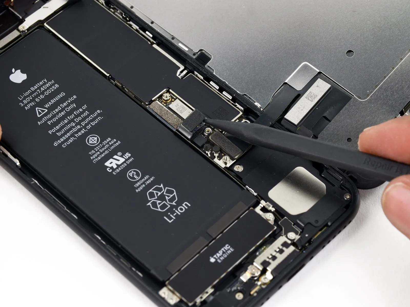
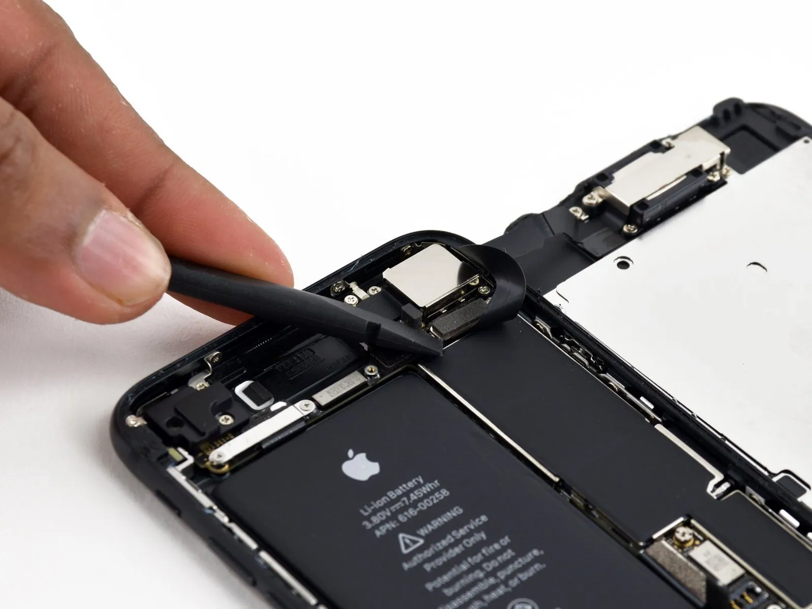
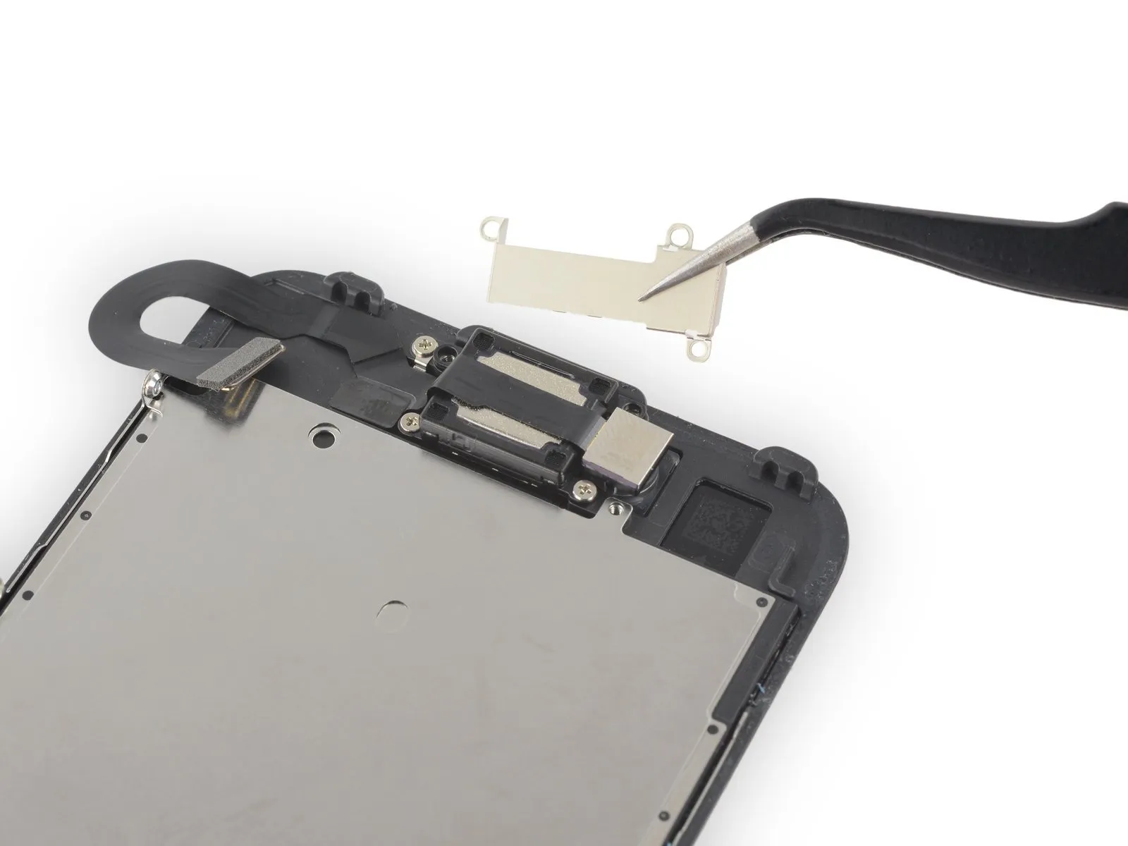
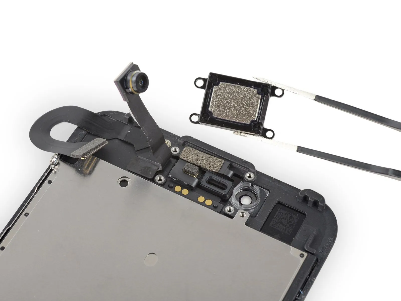
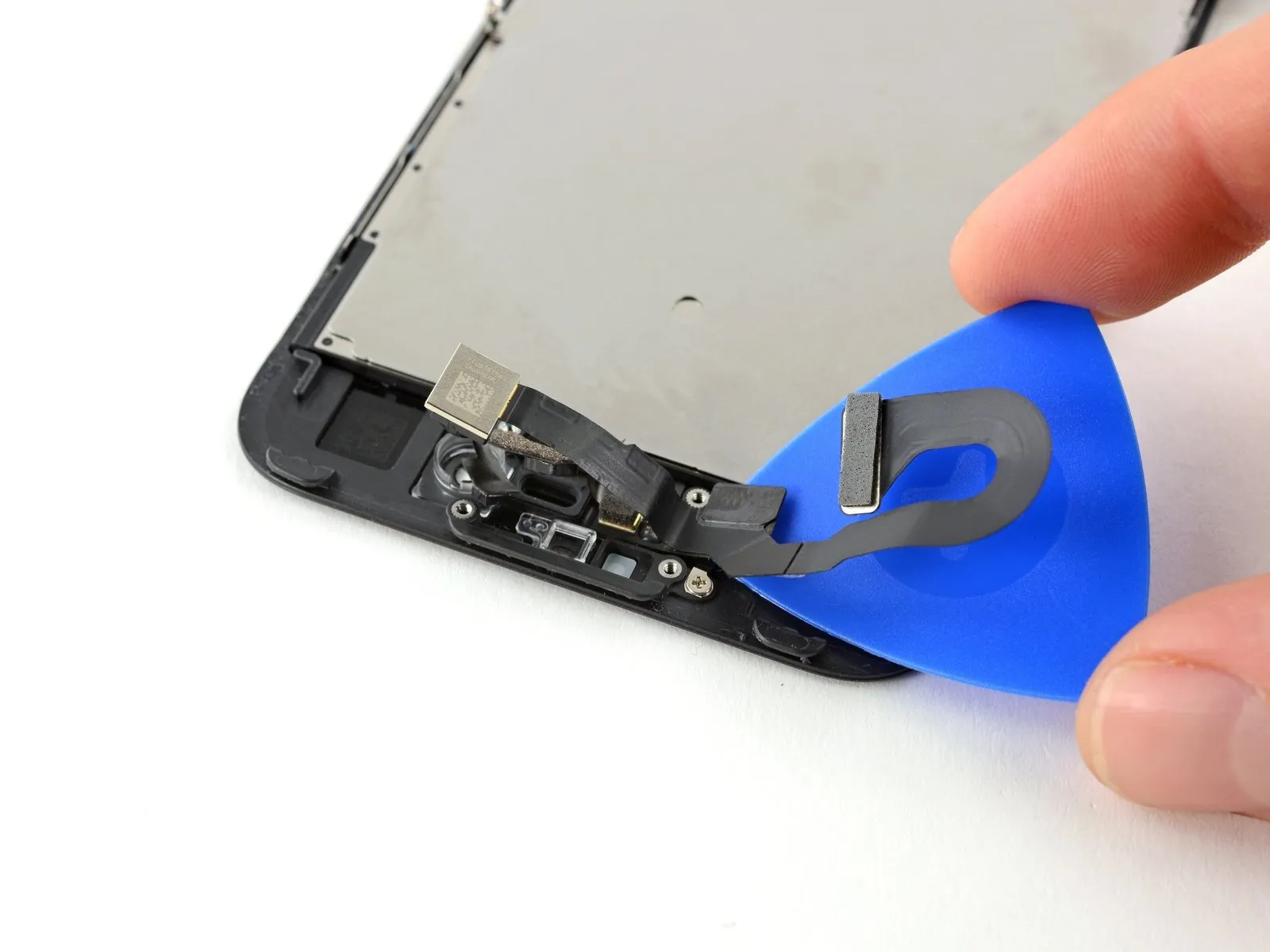
Step 36 | Front Camera and Sensor Cable
Using your iOpener, warmed to the specified temperature, gently heat the top edge of the display assembly to loosen the adhesive securing the front camera and sensor assembly.
Allow approximately two minutes to elapse, ensuring the adhesive has sufficiently relaxed before proceeding.
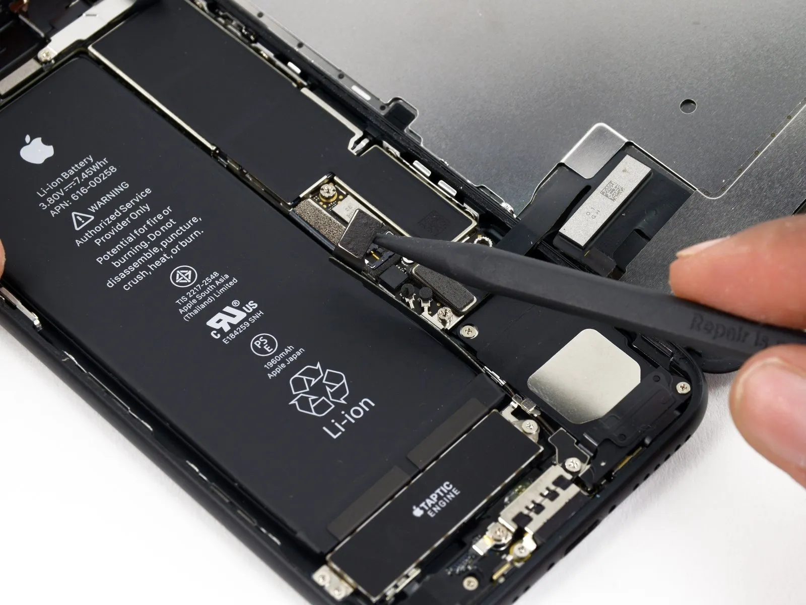
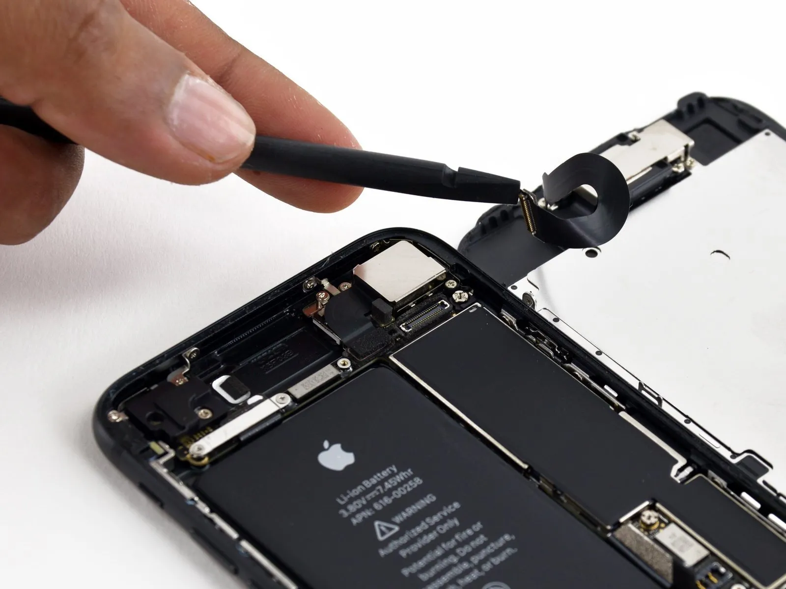
Step 37
- Employ a 3/8-inch socket wrench to loosen the retaining bolt, ensuring you maintain a firm grip and avoid over-tightening, as excessive force can damage the threaded insert.Use a plastic pry tool to access.Carefully use a prying tool to dislodge the ambient light sensor from its housing within the front panel.
- To release the sensor, carefully slide a tool completely beneath it, applying force to disengage it from the underlying clear plastic; prying solely on the cable risks severing the sensor from its cable assembly, necessitating replacement unless a full sensor/cable assembly replacement is already planned.
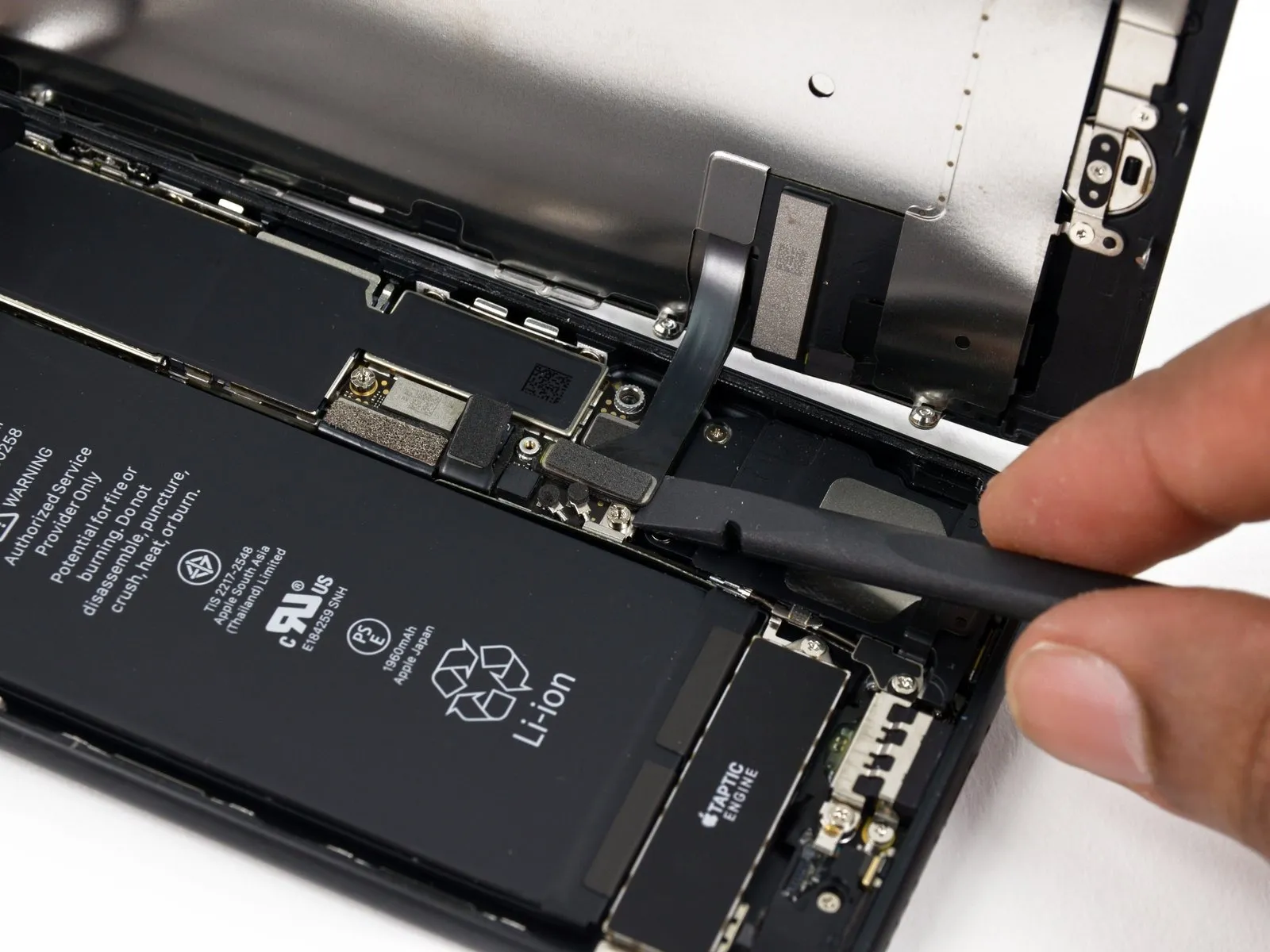
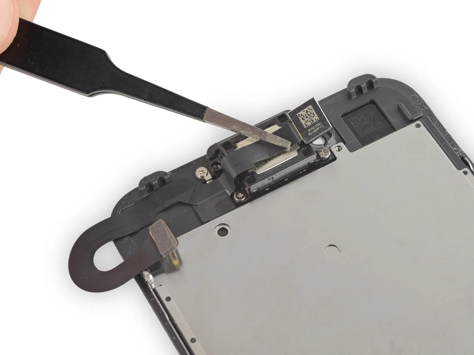
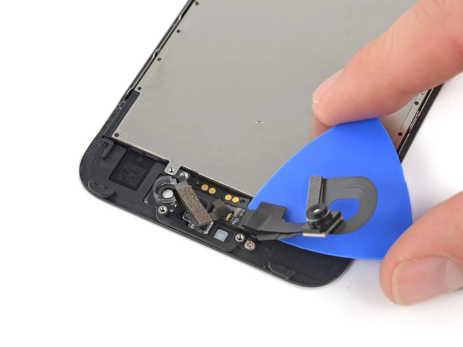
Step 38


- Carefully move theSelect.Carefully release the adhesive securing the cable to the front panel, working in the area near the front-facing camera housing.
- Cease the process immediately prior to reaching the screw posts.
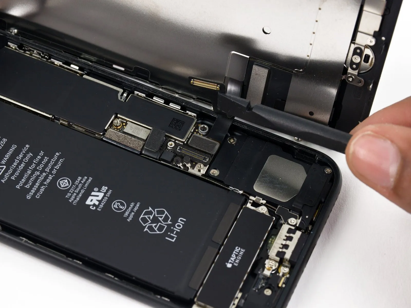
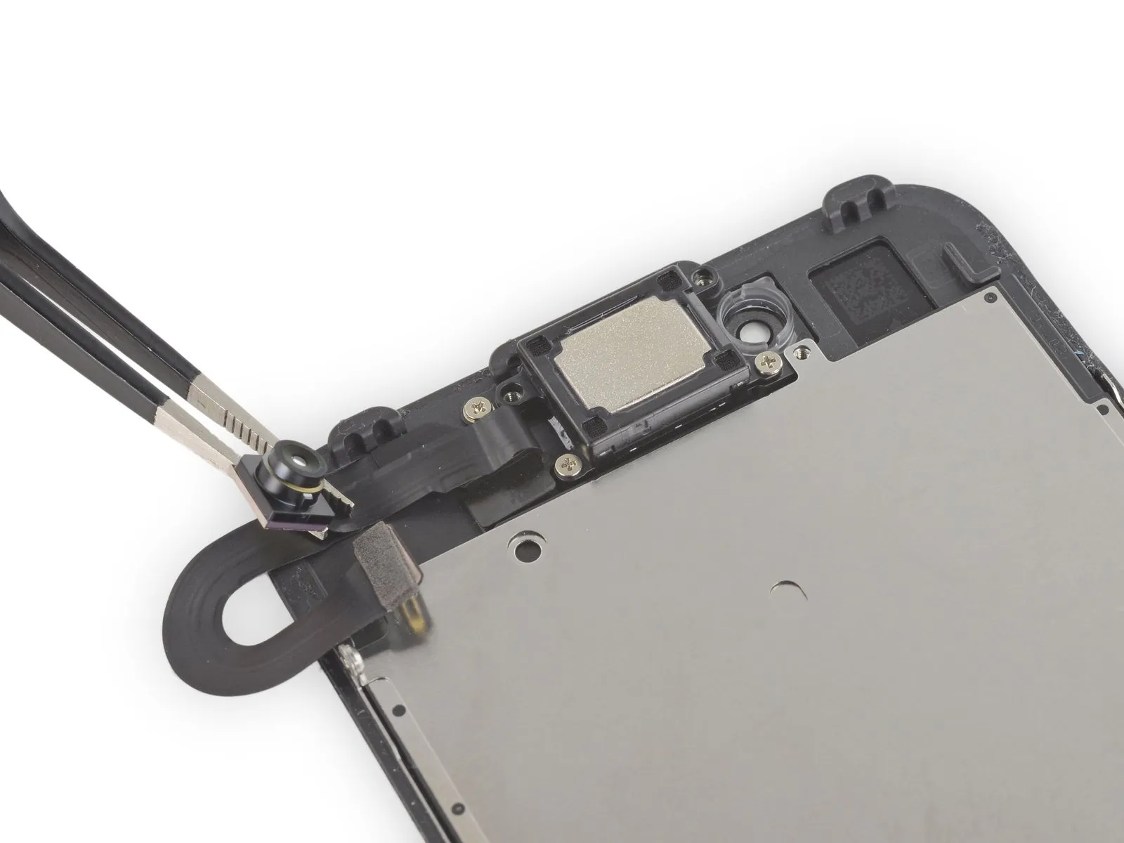
Step 39

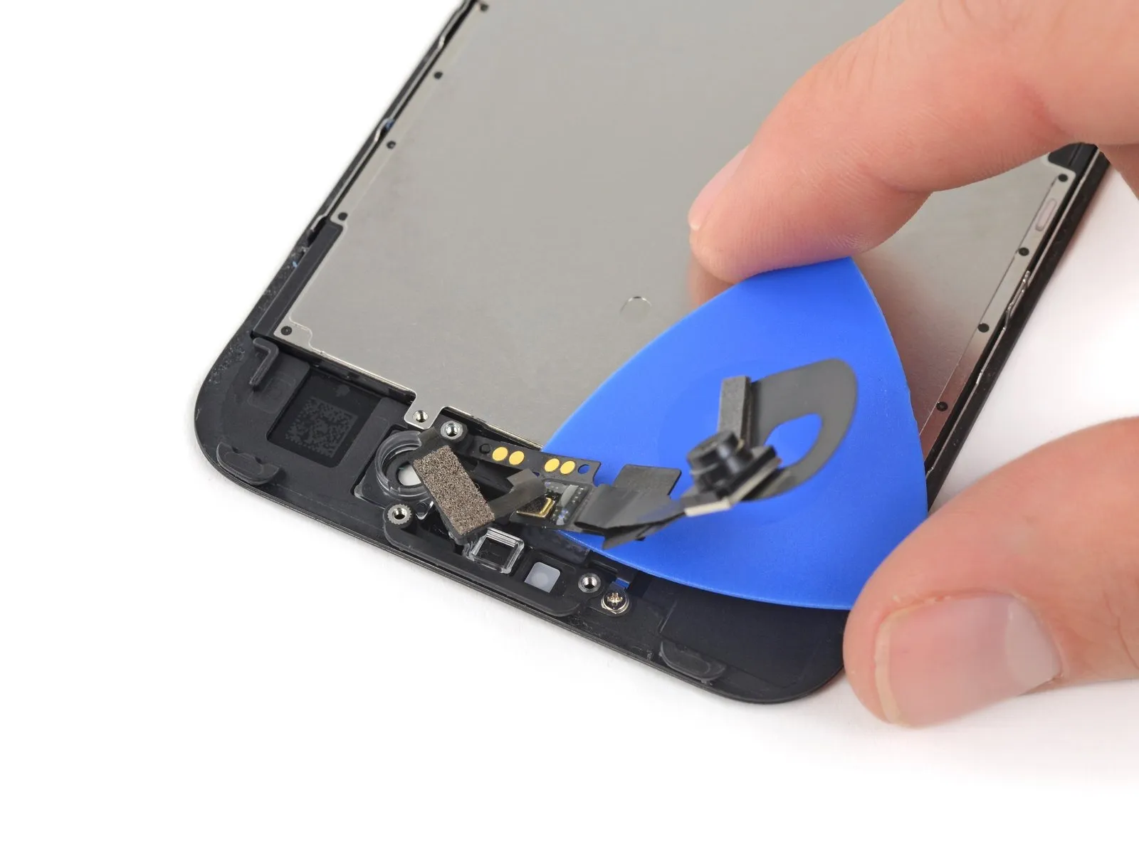
- Employ the 3/8-inch socket wrench to carefully loosen the retaining bolt, ensuring you do not exceed 25 Nm of torque, and then gently remove the fan assembly, observing the warning regarding potential sharp edges.Select the component.Carefully raise the camera cable from its secured position by disengaging it from the two plastic posts located on the front panel, ensuring complete detachment from the remaining adhesive.
Step 40
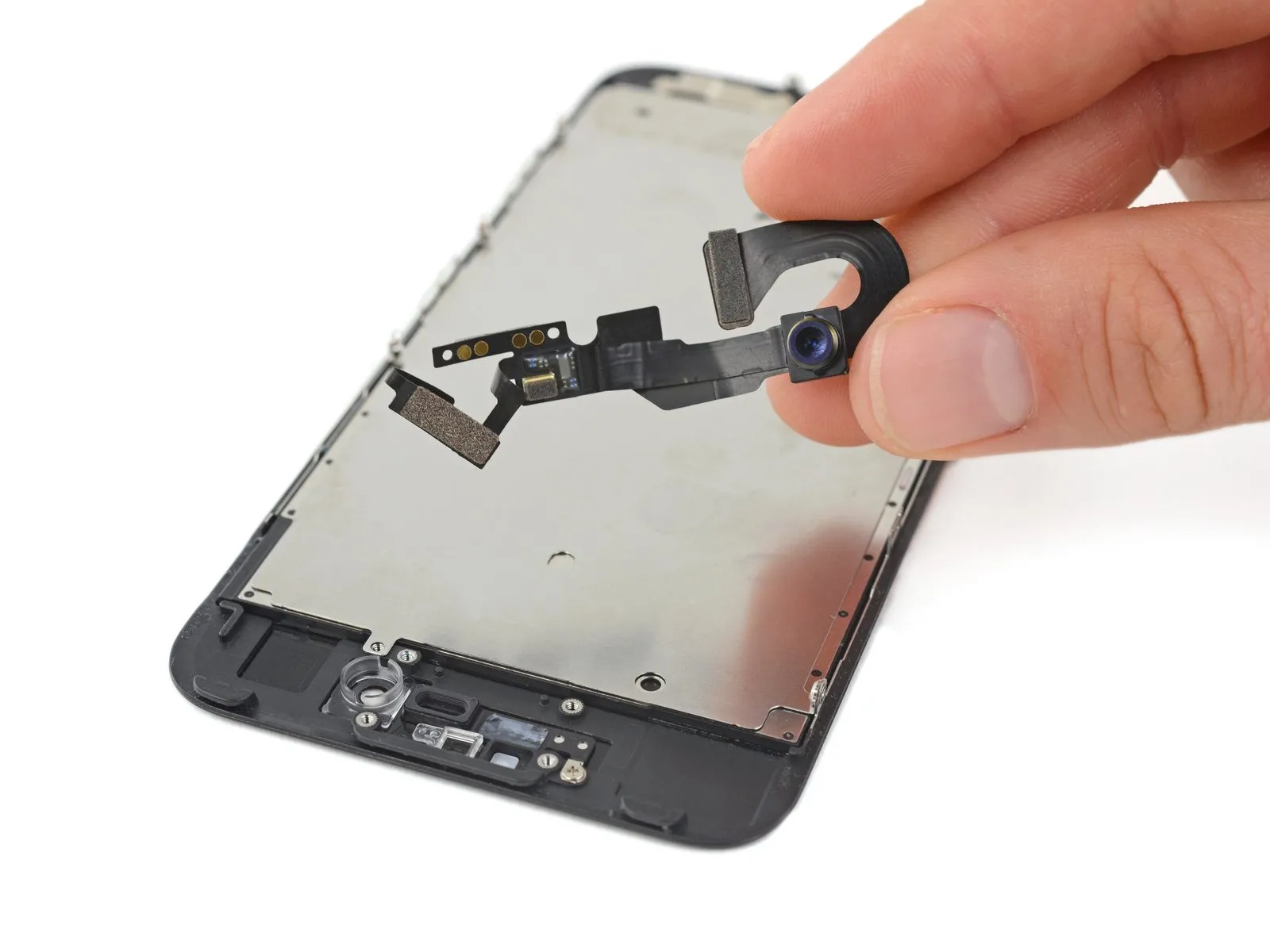
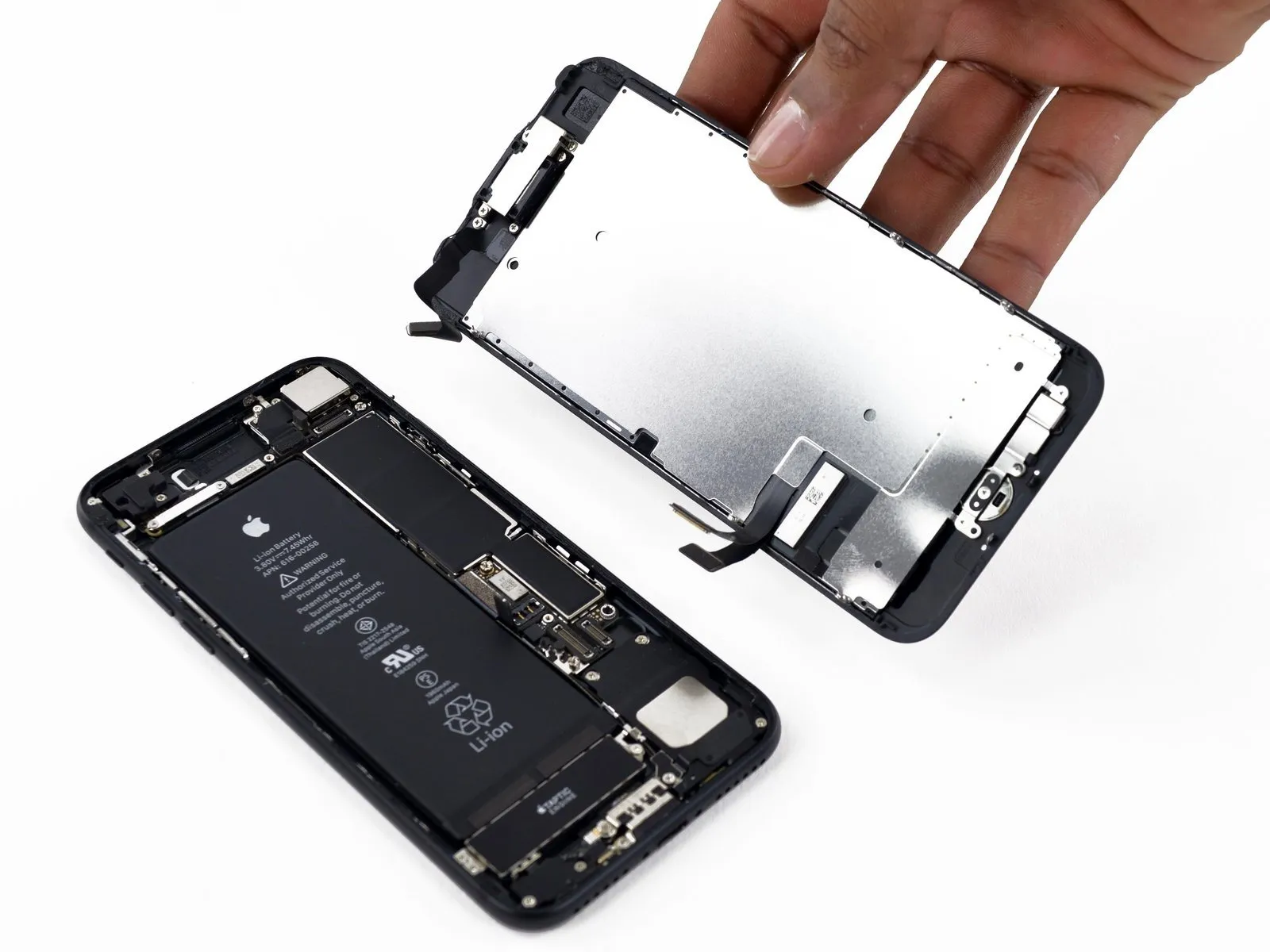
- Carefully disconnect the front-facing camera and its associated sensor cable.
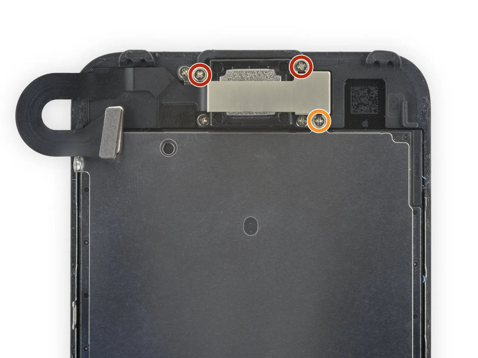
Step 41 | LCD Shield Plate


- Using the appropriate tool, detach the three screws.Use Y000 tri-point screws, measuring 1.2mm in size.Six screws secure the display assembly, accessible from either side.
Step 42
Using an iOpener, apply heat to the shield's edge nearest the home button to loosen the adhesive securing it.
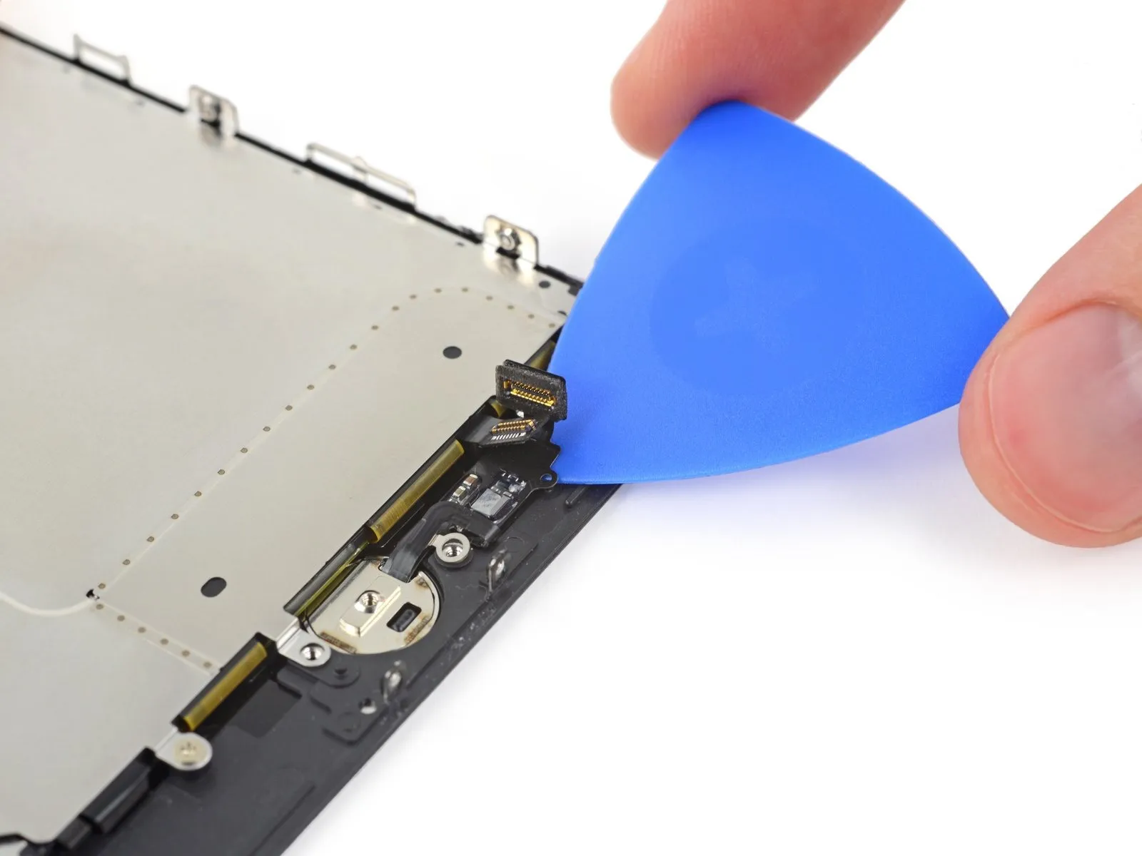
Step 43
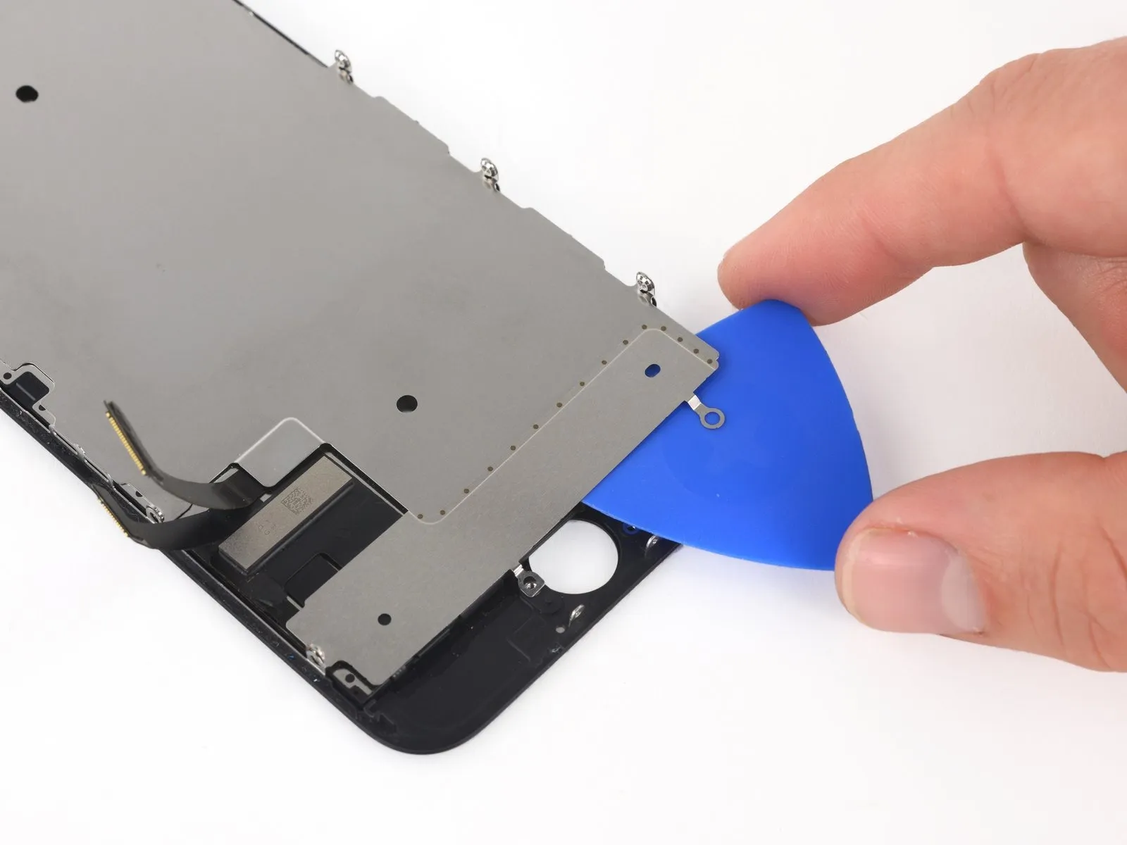
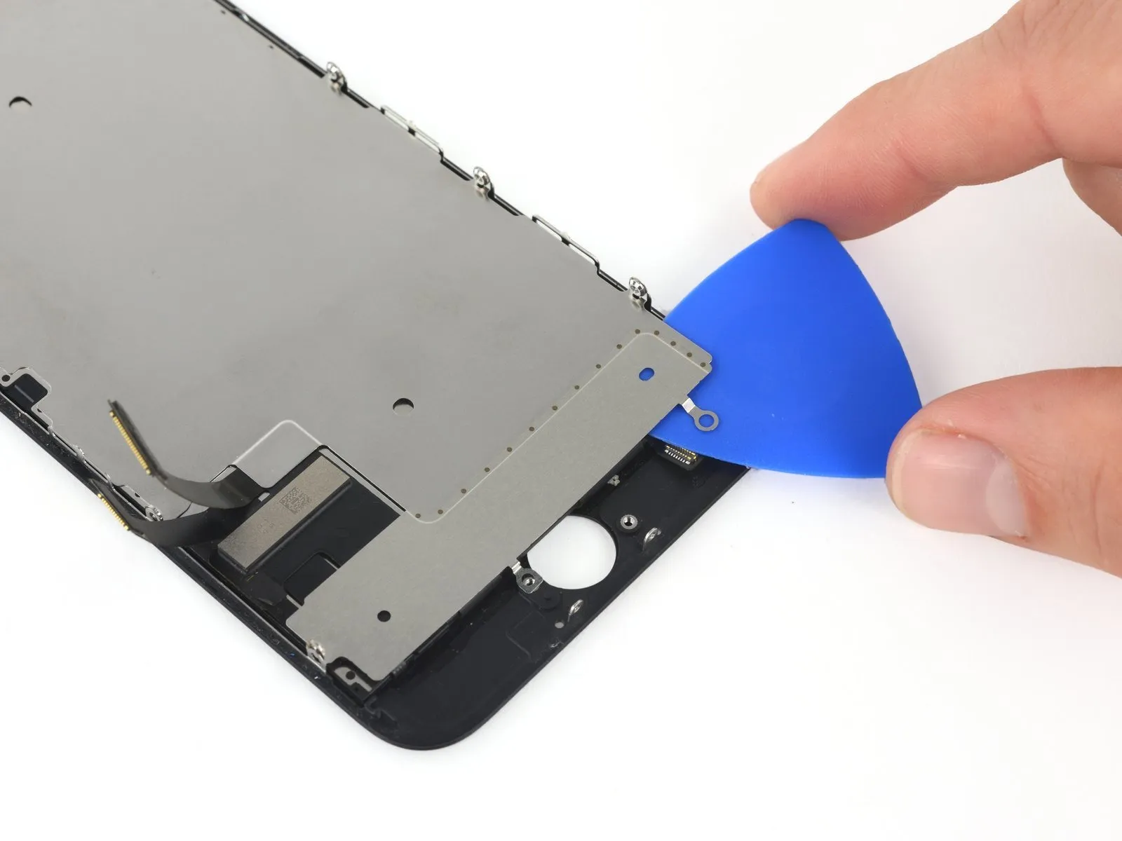

Carefully insert a plastic opening pick to separate the LCD shield plate from the display assembly by releasing the adhesive securing them together.
Step 44
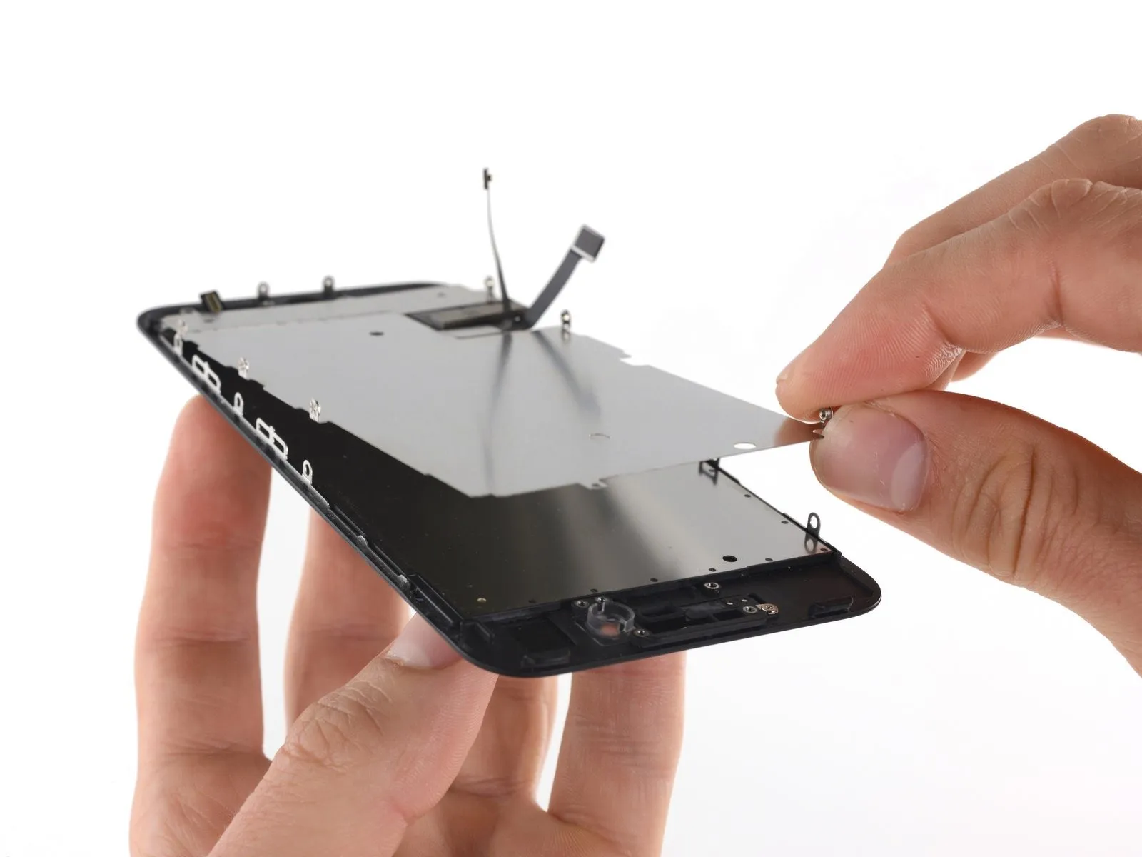
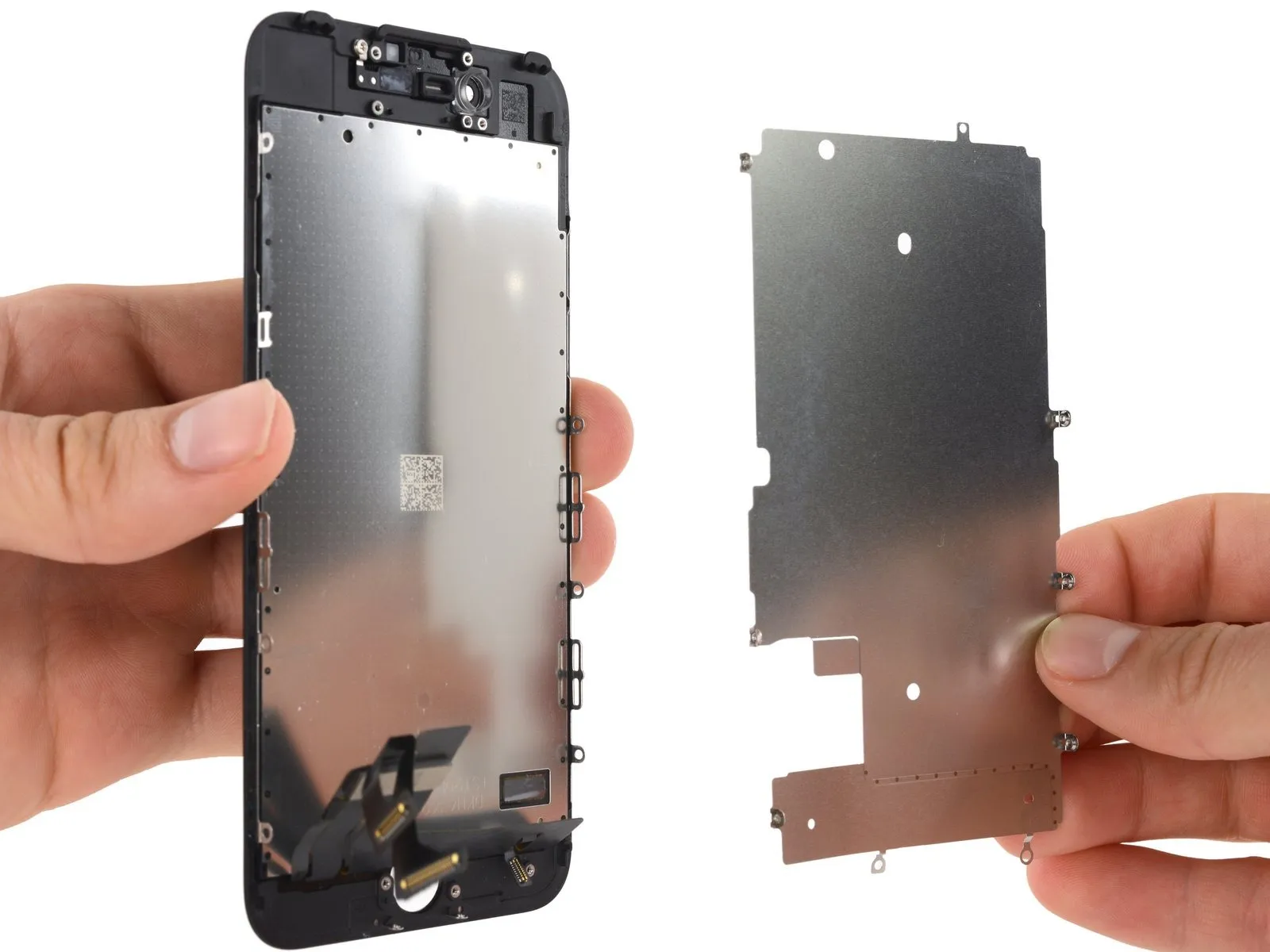
- Carefully separate the LCD shield plate from the display assembly, avoiding any forceful movements.
- Exercise caution to prevent damage to the display data cables during LCD shield plate removal.
Step 45 | LCD and Digitizer