iPhone 7 Lightning Connector Assembly Replacement
If the phone fails to recognize the charging cable, the charging port exhibits looseness, or the microphone is unresponsive, and cleaning the Lightning port hasn't restored charging functionality, proceed with further inspection.
Consider substituting the component if its operational lifespan has been reached.The connector for the Lightning cable.To complete this repair, follow the steps detailed for substituting the lower microphones and antenna cable.USB-C connector.
- Carefully observe that the specified torque of 25 Nm, achieved using a 10 mm socket and torque wrench, must be applied to secure the component, and failure to do so could result in damage.Expect to remove numerous components to complete this procedure.
- Carefully observe that the specified torque of 25 Nm, achieved using a 10 mm socket and torque wrench, must be applied when tightening the fastener to prevent damage to the component.Expect the process to be lengthy and demands careful attention to detail.
Step 1 | Pentalobe Screws
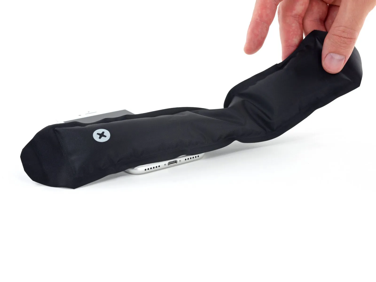
- To ensure optimal performance during this repair, deplete the iPhone's battery to a level below 25% prior to commencing work.A lithium-ion battery must be fully charged.A puncture can result in fire and/or explosion.
- To prevent electrical shock or damage, ensure the iPhone is completely de-energized prior to starting the repair process.
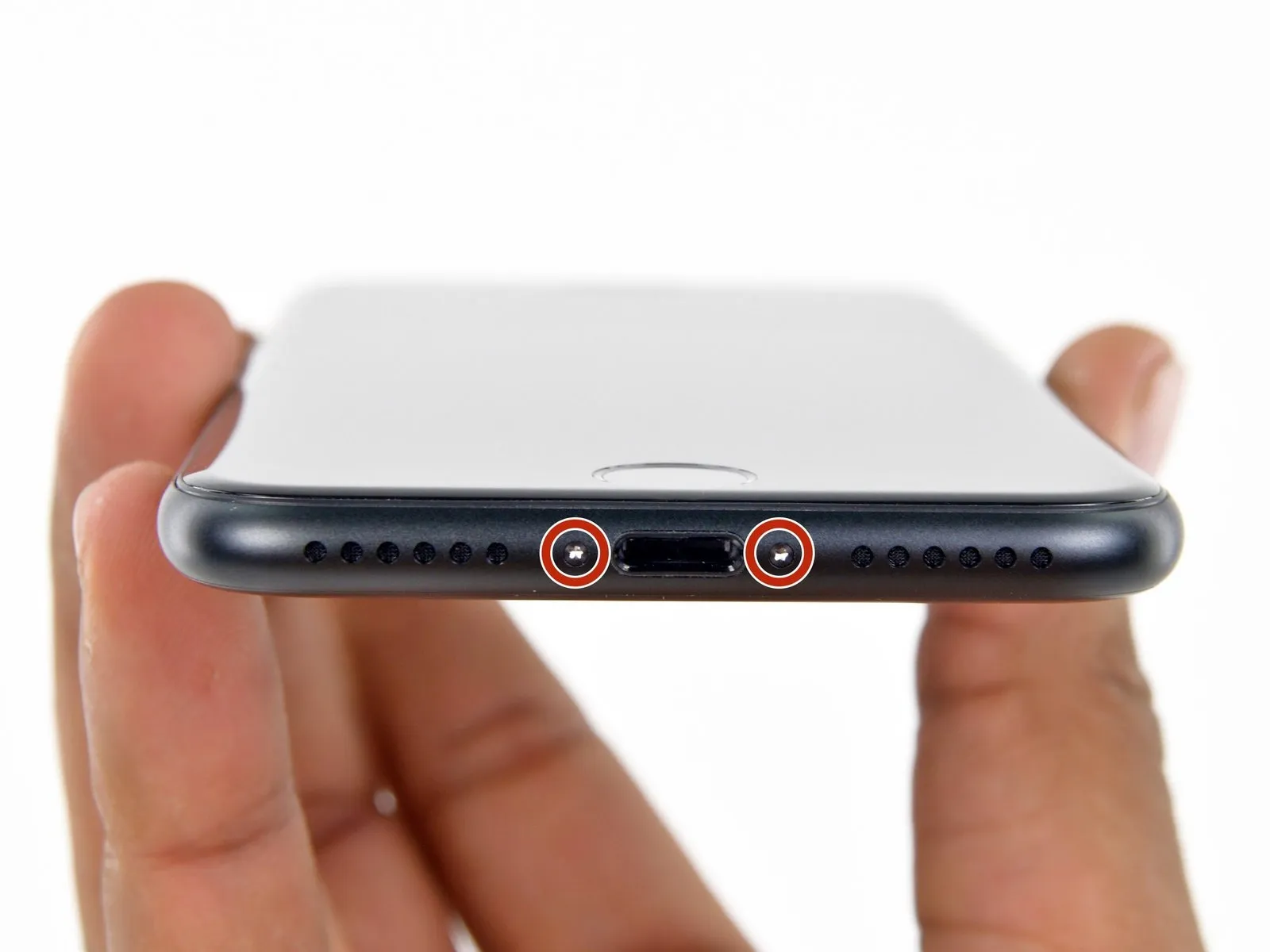
- Using appropriate tools, detach the iPhone's two screws, each measuring 3.4 mm in diameter and featuring a pentalobe head, located along the device's lower perimeter.
- Removing the display assembly will damage the iPhone's water resistance; ensure replacement seals are available for installation prior to proceeding, or exercise extreme caution to prevent liquid ingress if reinstalling the display without new seals.
Step 2 | Mark your opening picks


- To avoid potential damage to your device, ensure the opening pick does not extend beyond a safe depth; to help with this, mark the pick according to the following procedure.
- Determine the dimension using an appropriate measuring tool.Three millimeters.Using a permanent marker, clearly indicate the opening point on the pick.
- Alternative corner markings, using the same measurement tools, can be added to the remaining corners of the pick.
- Securely affix a coin to the tip of a pick using adhesive tape.Three millimeters.Beginning at the very end.
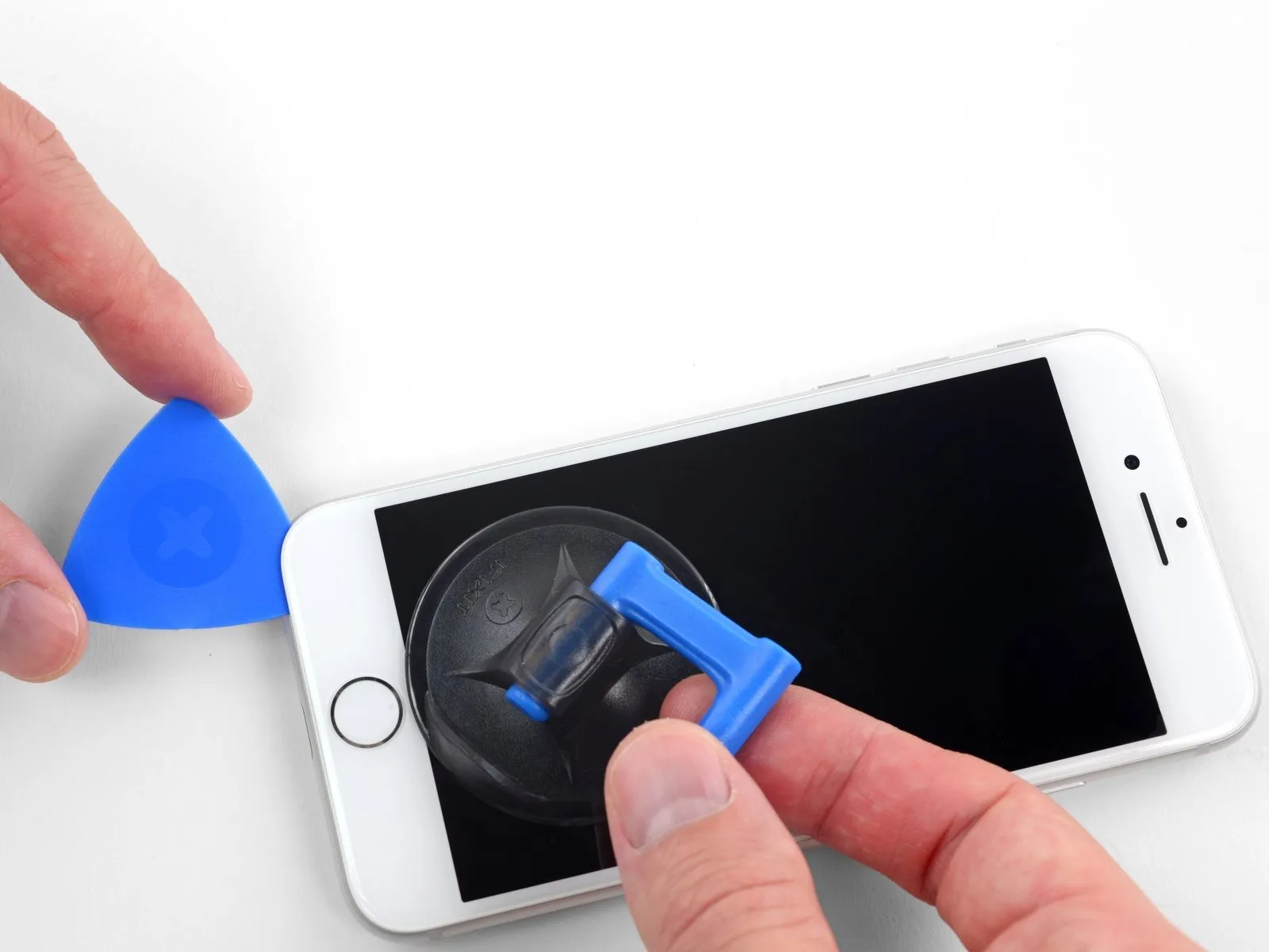
Step 3 | Anti-Clamp instructions


To simplify the opening process, the following three steps utilize the Anti-Clamp tool; if you do not have this tool, proceed directly to the method three steps further in the instructions.
Refer to the included guide for detailed procedures regarding Anti-Clamp operation.
- To release the Anti-Clamp's arms, move the blue handle in a rearward direction.
- Position the arms so they extend across the iPhone's left or right side.
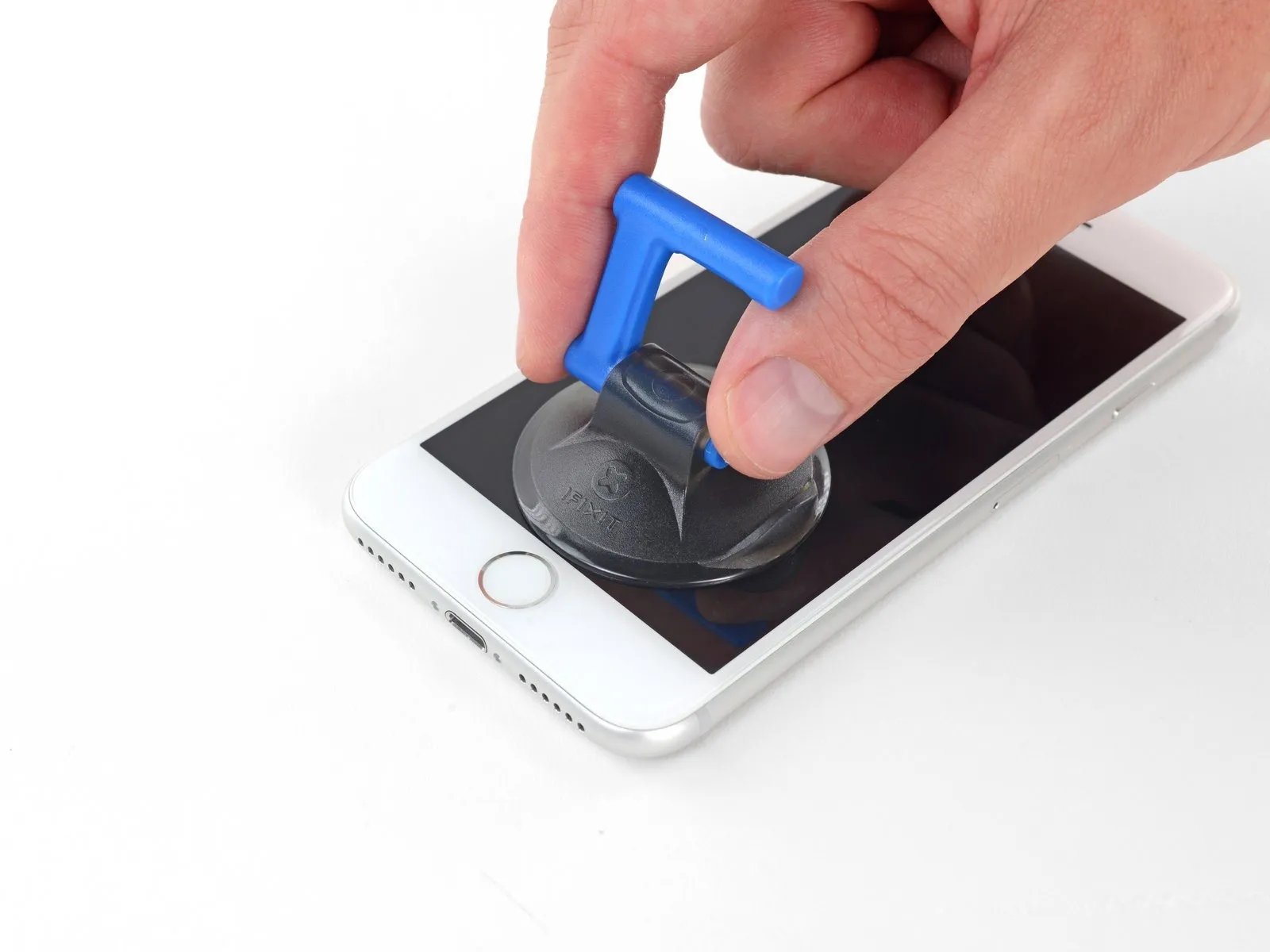
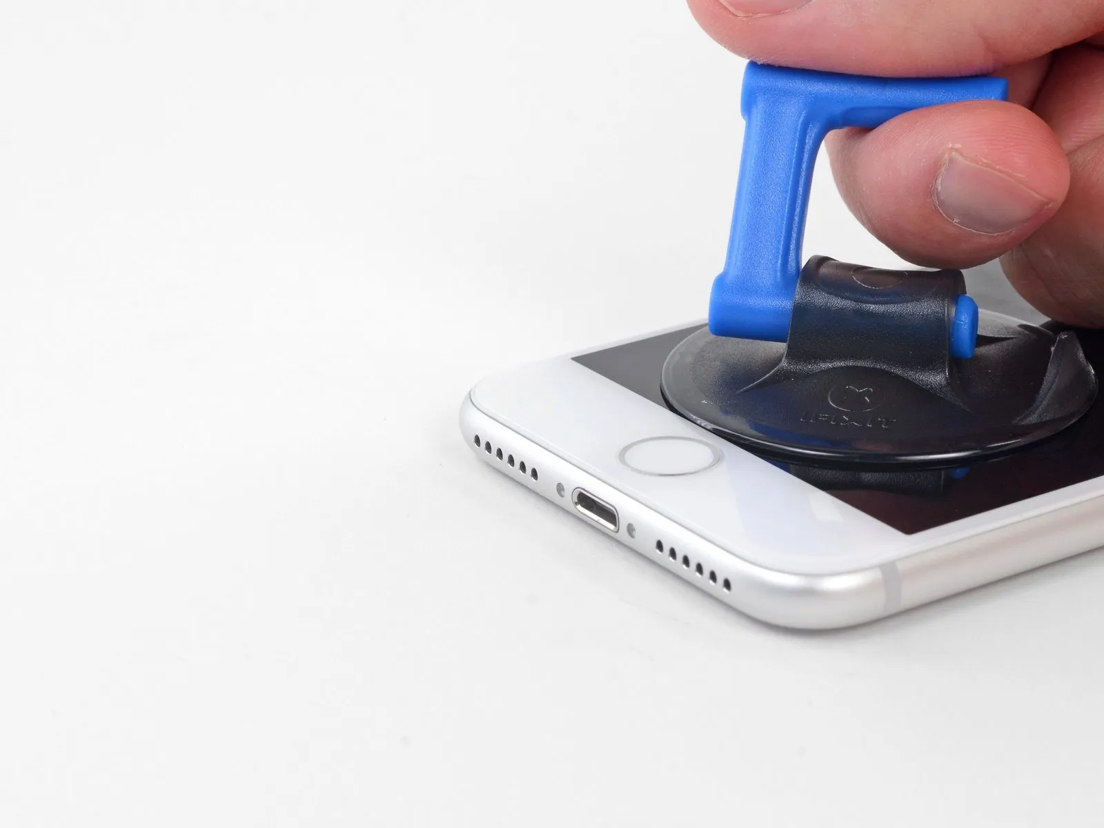
- Affix two suction cups, one to the front and one to the rear surface of the iPhone, close to the lower edge, situated directly above the home button.
- Apply vacuum to the targeted surface by pressing the cups firmly against each other.
- To improve the Anti-Clamp's grip if the iPhone's exterior feels excessively smooth, apply adhesive tape to the device's surface.
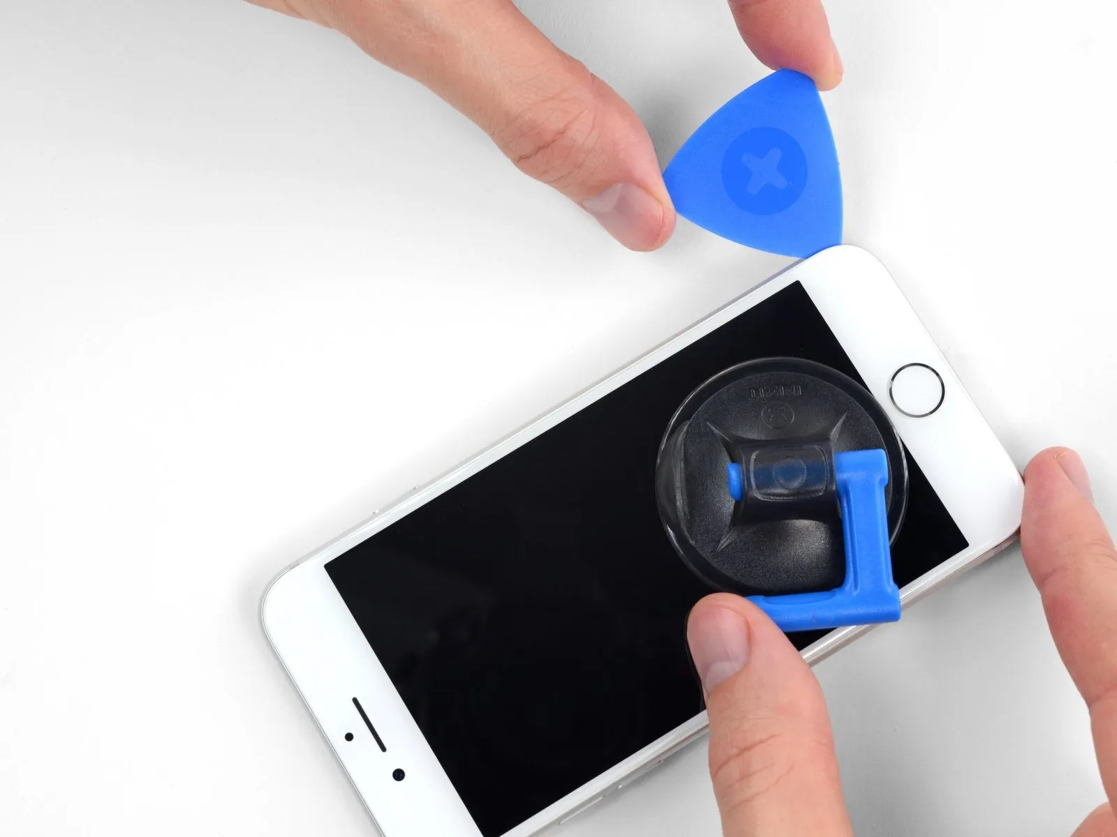
Step 4


- To secure the arms, advance the blue handle in the direction indicated.
- Rotate the handle in a direction that tightens it.Rotate fully around its axis.Monitor the process, stopping when the cup material begins to visibly expand.
- Maintain parallel positioning of the suction cups; should misalignment occur, gently reduce the suction and reposition the arms.
Step 5


- Apply heat to the component using a heat gun.Use the iOpener.Carefully guide the thread through the armholes.Prevent clamping..
- To warm the display and/or battery, a hair dryer, heat gun, or hot plate may be employed; however, exercise caution as excessive heat could harm these components.
- Carefully bend theUse the iOpener.Position the component flush against the lower edge of the iPhone's casing.
- Allow a full 60 seconds for the adhesive to soften and create a separation.
- Using a specialized opening tool, carefully introduce its tip into the separation.
- Carefully disconnect the 12-volt battery, then use a 3/8-inch wrench to loosen the hose clamp securing the radiator hose to the thermostat housing, allowing for removal of the hose.Prevent clamping.If the separation isn't adequate, increase the heat applied to the region and adjust the handle's position by 90 degrees.
- To prevent damage, rotate the component no more than 90 degrees, pausing for a full minute after each adjustment.Employ a device designed to prevent clamping.Allow the specified duration for the process to complete automatically.
Step 6 | Heat the display
Employing a suction cup, proceed with the following three steps to detach the display assembly.
- Applying heat to the phone's bottom perimeter will loosen the adhesive that holds the display in place, facilitating separation.
- Apply heat with a hairdryer or use a heat gun to warm the adhesive securing the component, ensuring the temperature does not exceed 150°F (65°C).Use a specialized iOpener tool to gently apply even heat across the device's perimeter, maintaining a temperature no higher than 100°F (38°C) to soften the adhesive securing the display assembly.To loosen the adhesive securing the lower portion, hold a heat source against that edge for roughly 90 seconds.
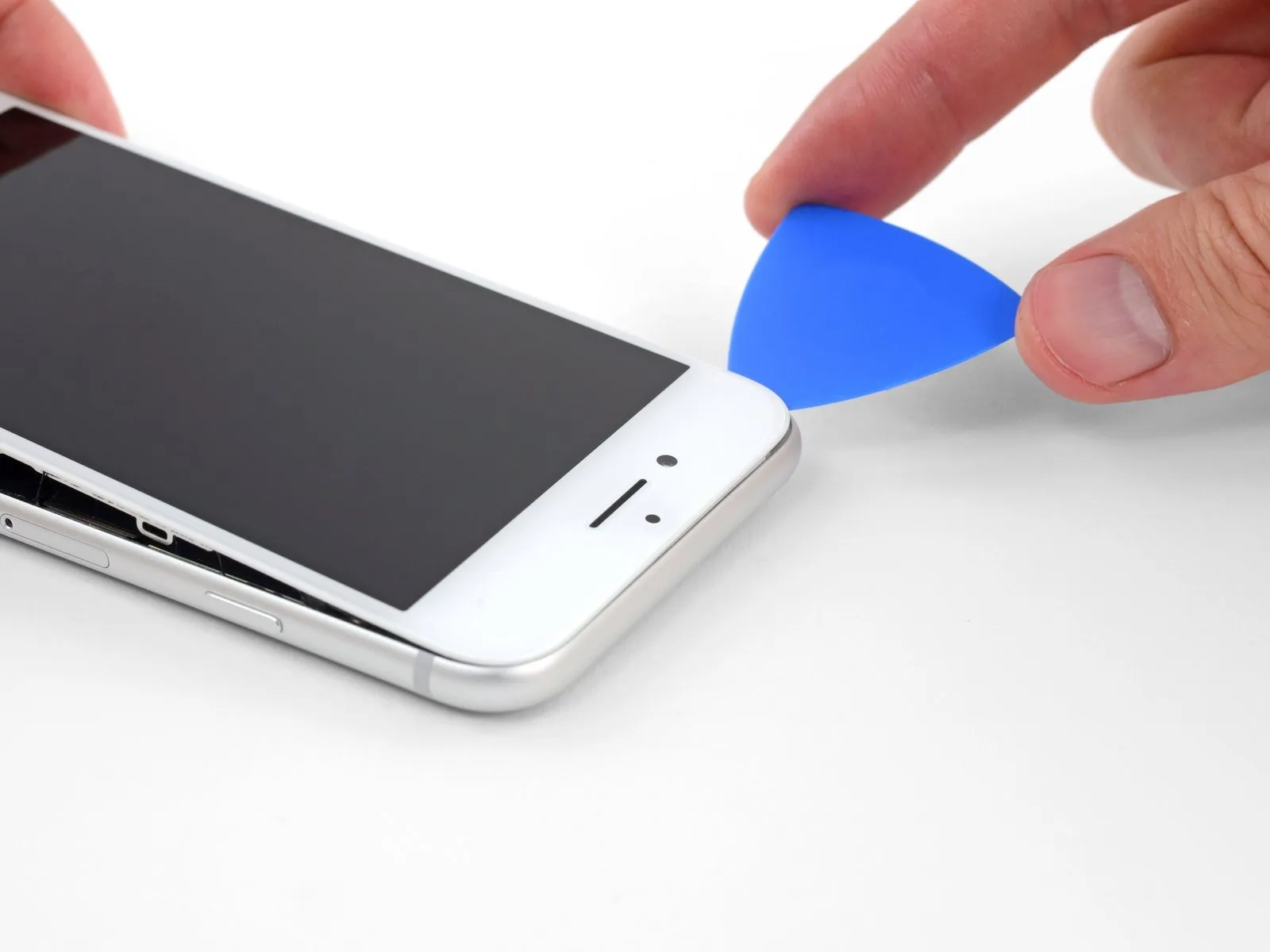
Step 7 | Separate the display

Position a suction cup directly on the front panel's bottom section, situated immediately above the home button.
To ensure a proper seal between the suction cup and the front glass, avoid positioning the cup so that it covers the home button.
Step 8


- Apply steady, even force to lift the suction cup, generating a minimal separation between the display assembly and its surrounding frame.
- Using a specialized opening tool, carefully slide its tip into the separation.
- Due to the robust nature of the watertight adhesive securing the screen, separating it requires considerable force. Should you encounter difficulty, apply additional heat and incrementally move the screen back and forth to soften the adhesive, allowing for a gap sufficient to accommodate your tool.
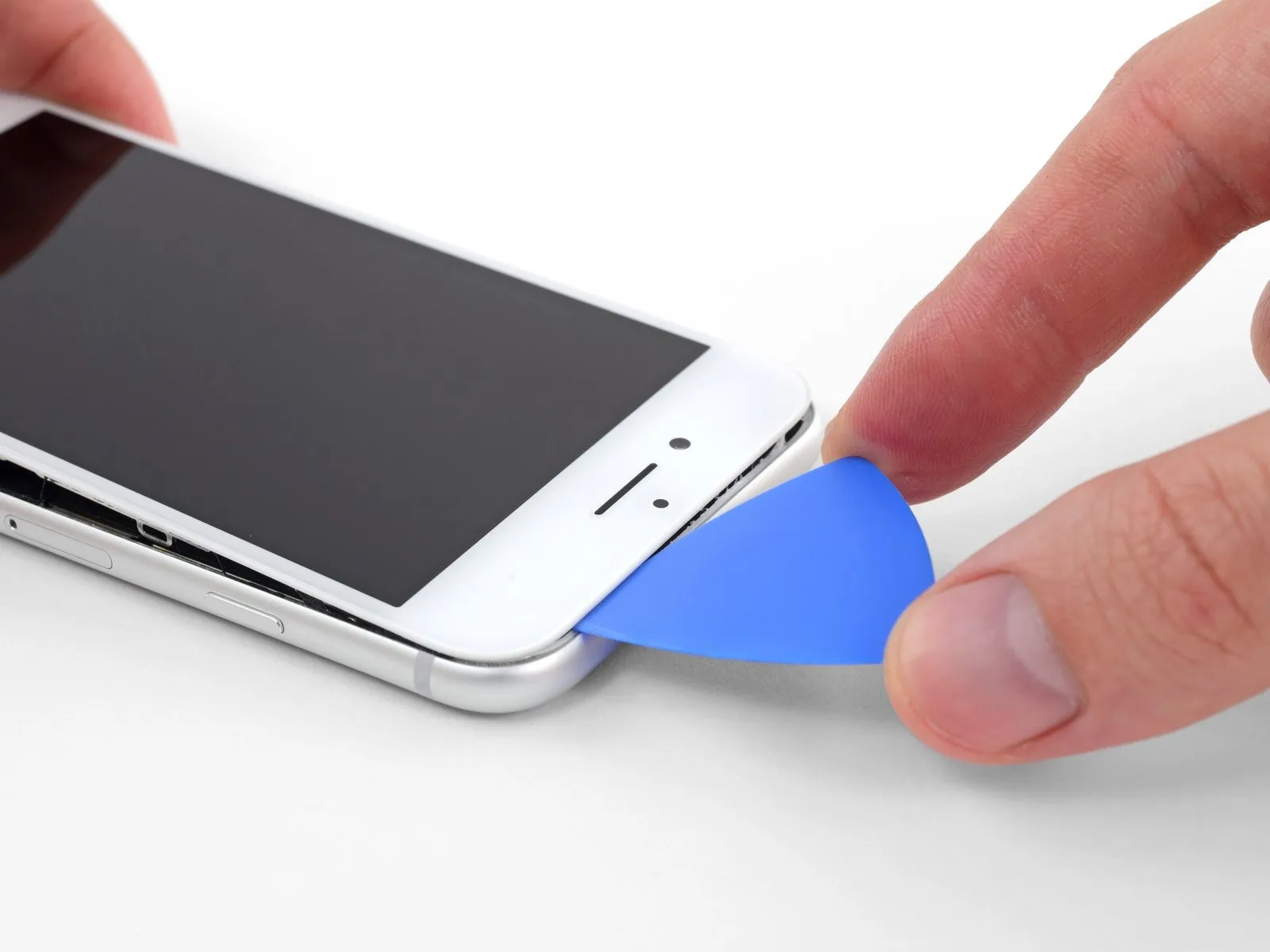
Step 9


- Using a pick, carefully separate the display from the phone's frame by inserting it between the left edge and the chassis, beginning at the bottom and progressing upwards toward the volume buttons and silent switch, to release the adhesive securing the display.
- Position yourself close to the upper-left edge of the screen.
- Avoid separating the display's upper border from the back cover by force; delicate plastic fasteners secure it, and applying excessive pressure risks their damage.
Step 10 | Screen information

Avoid forcing any tools into the right side of the iPhone, as the sensitive internal wiring located there is susceptible to damage.
Step 11


- Using your tool, begin at the lower-right edge of the iPhone, then move it along the edge and upward along the right side to release the adhesive.
Avoid pushing the tool beyond the specified depth.Three millimeters.Carefully proceed to avoid harming the display cables.
Step 12


- Using a gentle upward motion, disengage the display from its housing by lifting the lower perimeter with the suction cup.
The display's upward angle must not exceed .Set the temperature dial to 150 degrees.Careless handling could damage the display's ribbon cables, potentially causing them to stretch or rip.
To detach the suction cup, grasp the small projection extending from its surface and apply traction.
Step 13

- Using an opening pick, carefully separate the adhesive securing the display by inserting it between the display and the phone's frame, starting at the upper-left corner and working along the top edge.
Step 14


- To release the retaining clips securing the display assembly to the rear case, gently move the display downwards, shifting it away from the phone's upper edge.
Step 15


- Carefully detach the display assembly from the enclosure by pivoting it upwards, initiating the movement from the left edge, mirroring the action of opening a book's cover.
Avoid attempting this procedure.Despite appearing detached, the display remains linked to the iPhone's logic board via multiple delicate ribbon cables, requiring careful disconnection for complete separation.
To allow hands-free access during the repair process, support the display using a stable object.
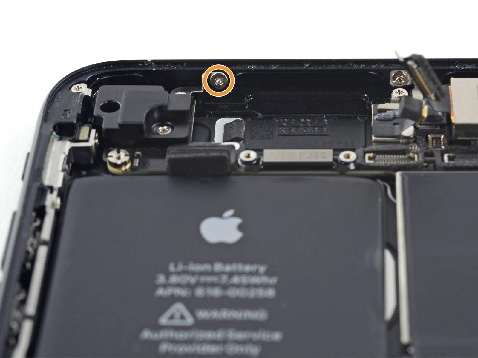
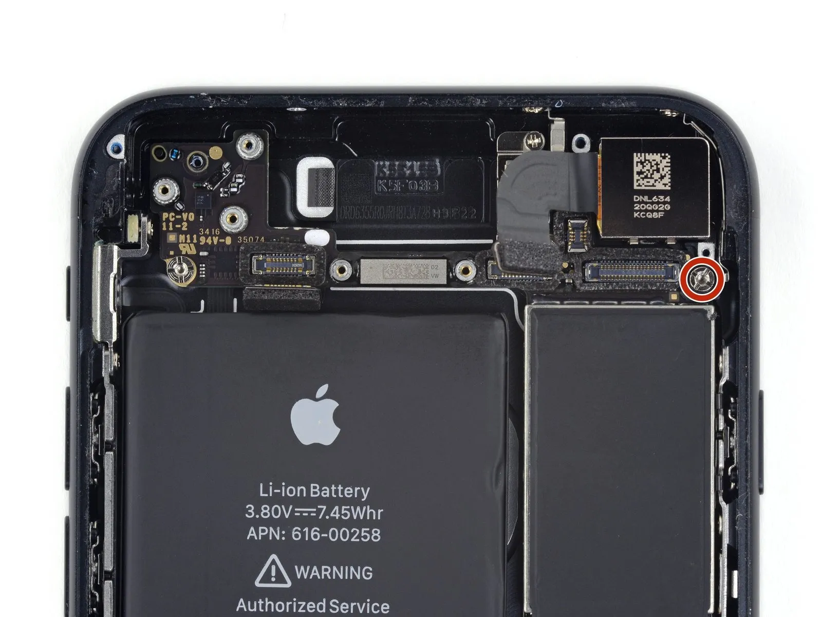
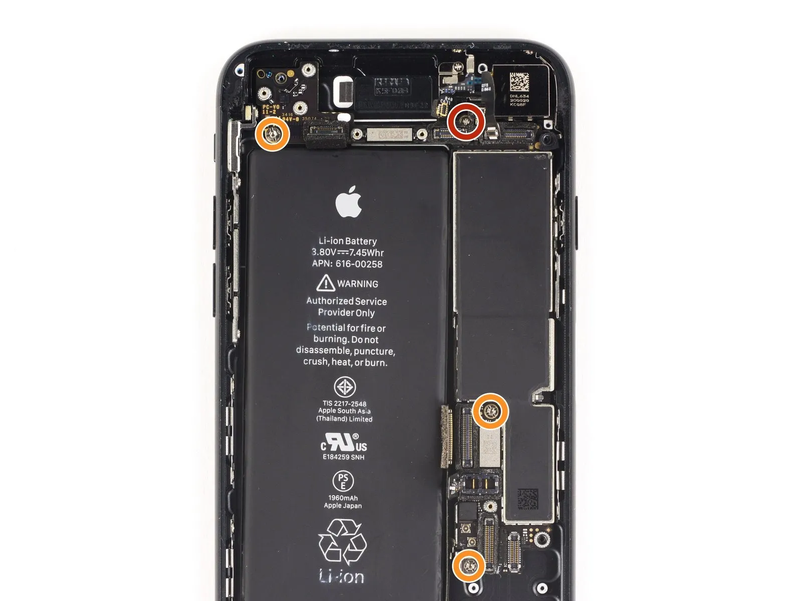
Step 16 | Battery Disconnection
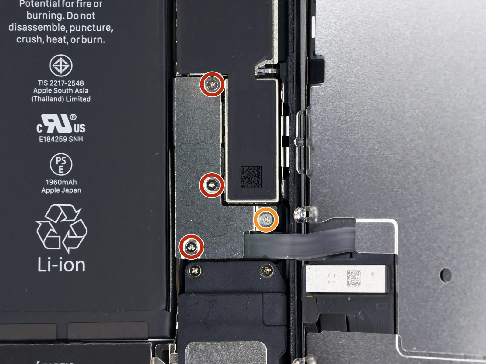
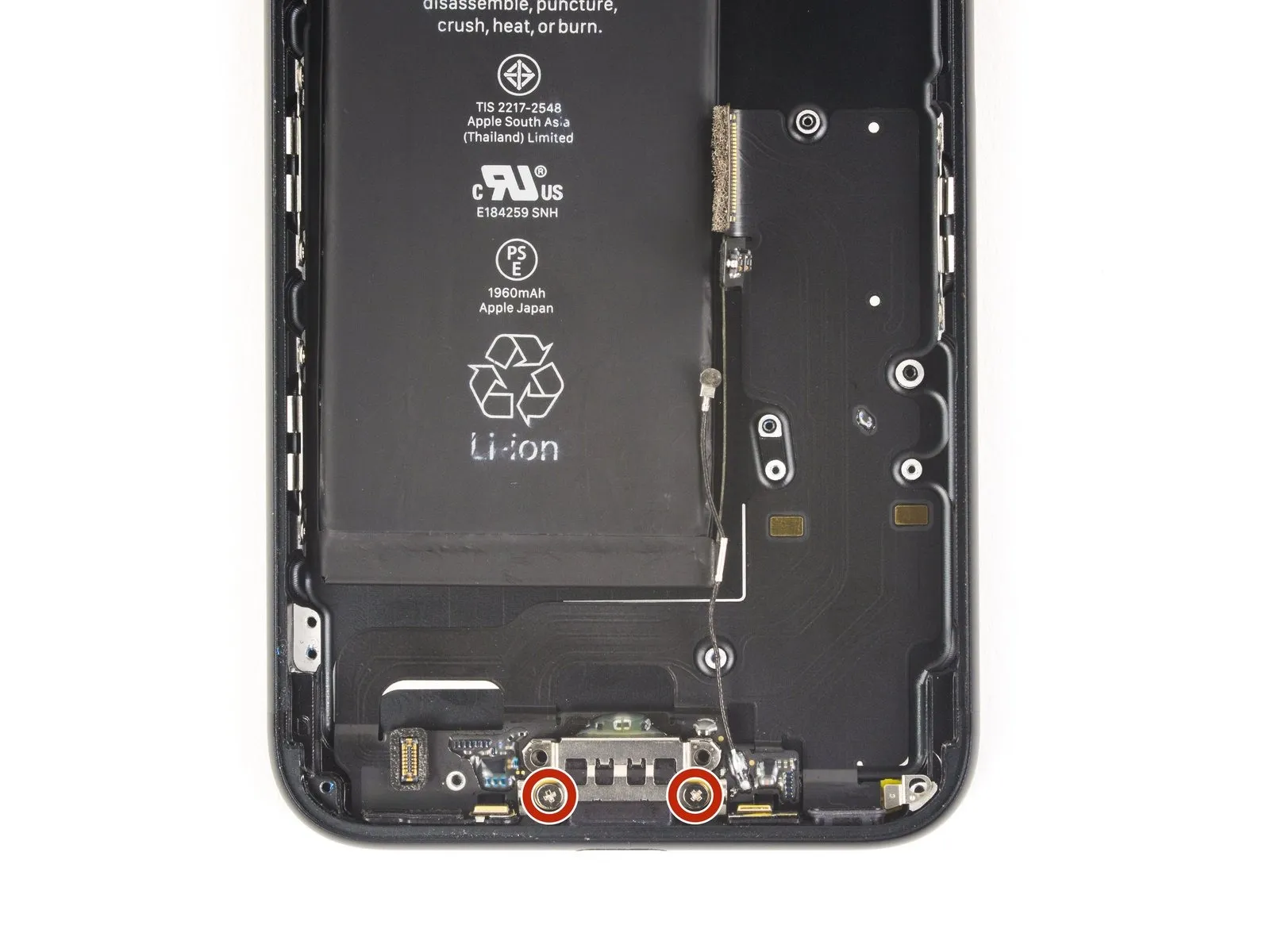
Detach the component.The lower connector bracket is held in place by four screws, each with a Y000 tri-point head, and these screws measure the following lengths.
- Use three screws, each measuring 1.2 millimeters.
- A screw with a 2.4-millimeter head diameter is required.
During the entire process, adhere strictly to all safety precautions and utilize the specified tools and measurements, including a 5mm hex key, a torque wrench calibrated to 10 Nm, and appropriate personal protective equipment, to prevent damage to components and ensure a safe working environment.Carefully note the location of every screw during disassembly, as reassembly requires placing each one in its original position to prevent iPhone damage.
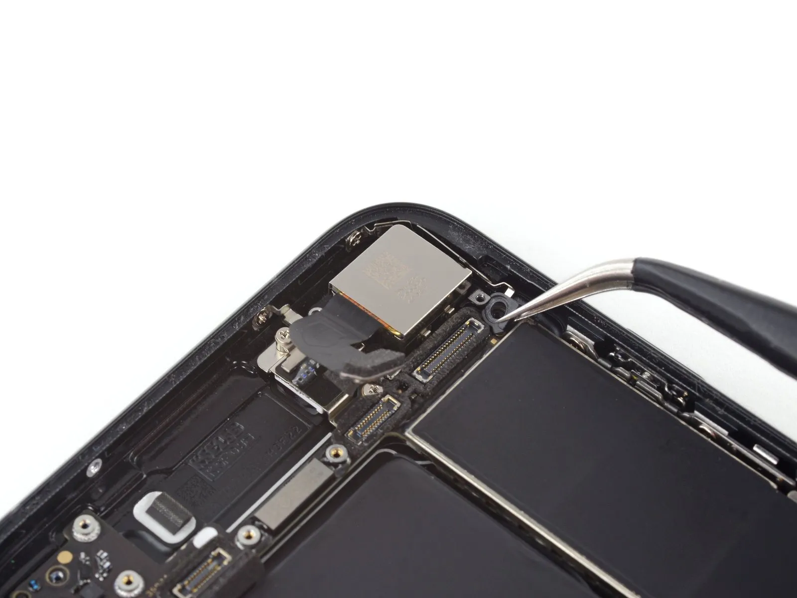
Step 17
Step 18
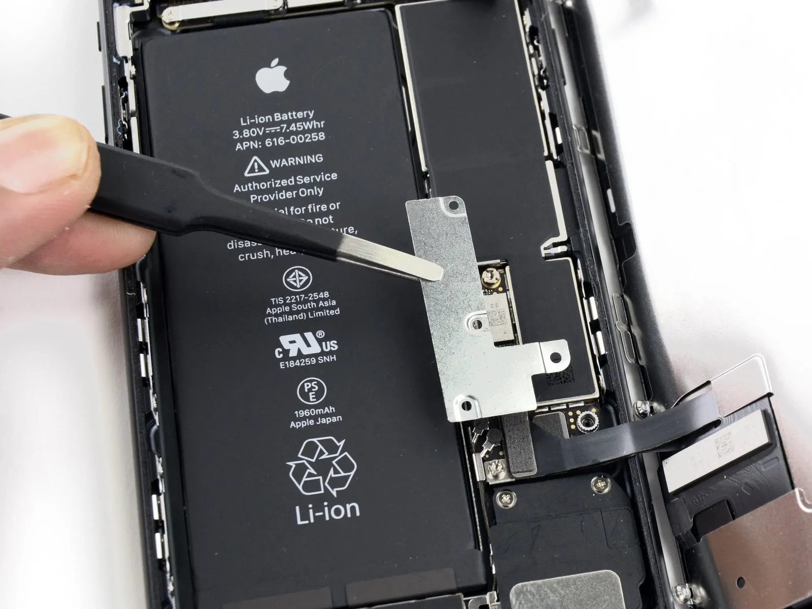
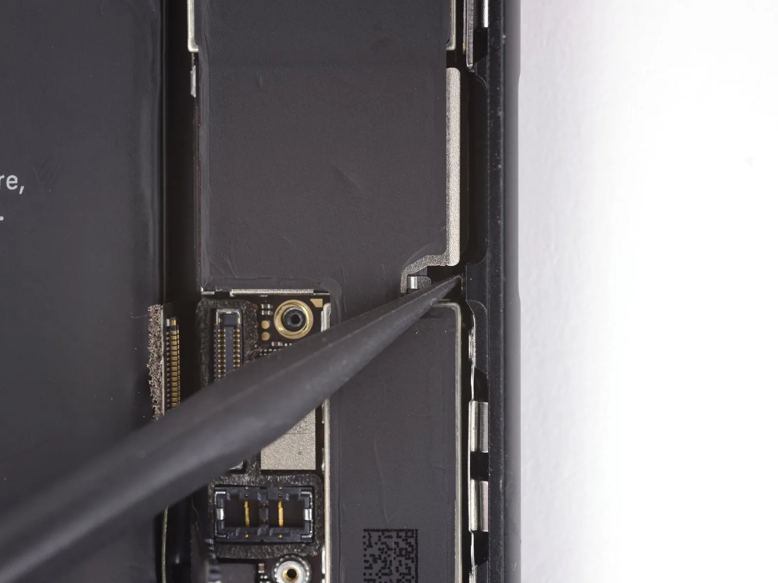
- Carefully employ the tip of a screwdriver to apply pressure.Use a plastic spudger.Carefully disengage the battery connector from its receptacle on the logic board.
- To avoid accidental power-up via the socket, gently raise the connector cable a small amount.
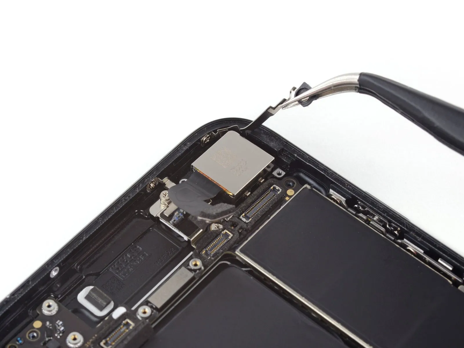
Step 19 | Display Assembly
- Prior to either detaching or reattaching the cables in this procedure, ensure the battery's power is completely isolated.
- Employ a 3/8-inch socket wrench to loosen the fastener, ensuring you apply even pressure to prevent damage to the retaining clip and observe the torque specification of 12 Nm as indicated in Table 2.Use a plastic pry tool, often referred to as a spudger, to gently separate components.Ensure the component is secured and properly aligned before proceeding.Use a fingernail.Using a suitable tool, carefully lift the two lower display connectors vertically away from their corresponding sockets on the logic board to release them.
- Ensure both ends of the cable are properly seated by applying even pressure until a distinct click is heard; avoid applying pressure to the central portion of the connector. Slight misalignment during connection can result in bending and irreversible damage.
- Following reassembly, a non-functional display—characterized by a blank screen, white lines, or unresponsive or limited touch functionality—may be resolved by carefully disengaging and then firmly reseating both display cables to ensure proper connection.
Step 20
- Detach the pair of fasteners.One point three millimeters. Use a Phillips head screwdriver, size 000.Fasten the bracket to the front panel sensor assembly connector using screws.
- Certain phone models may incorporate a Y000 component, a part Apple introduced during the mid-point of the device's production run.
Step 21
- Carefully detach the connector linking the front panel sensor assembly to its socket on the logic board.
- To reduce the possibility of deformation, reconnect the press connector by attaching one end at a time.
Step 22
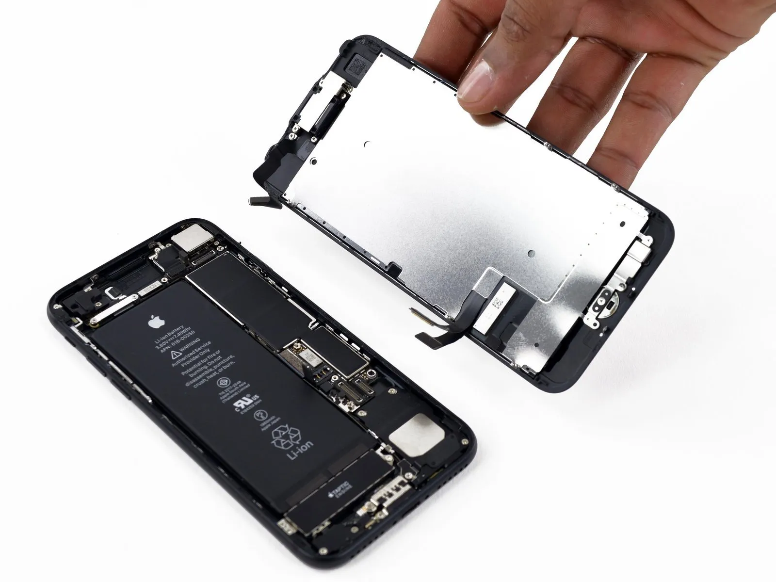
- Carefully detach the display assembly, ensuring all connections are released.
- If a display adhesive replacement is desired, stop the reassembly process at this point.
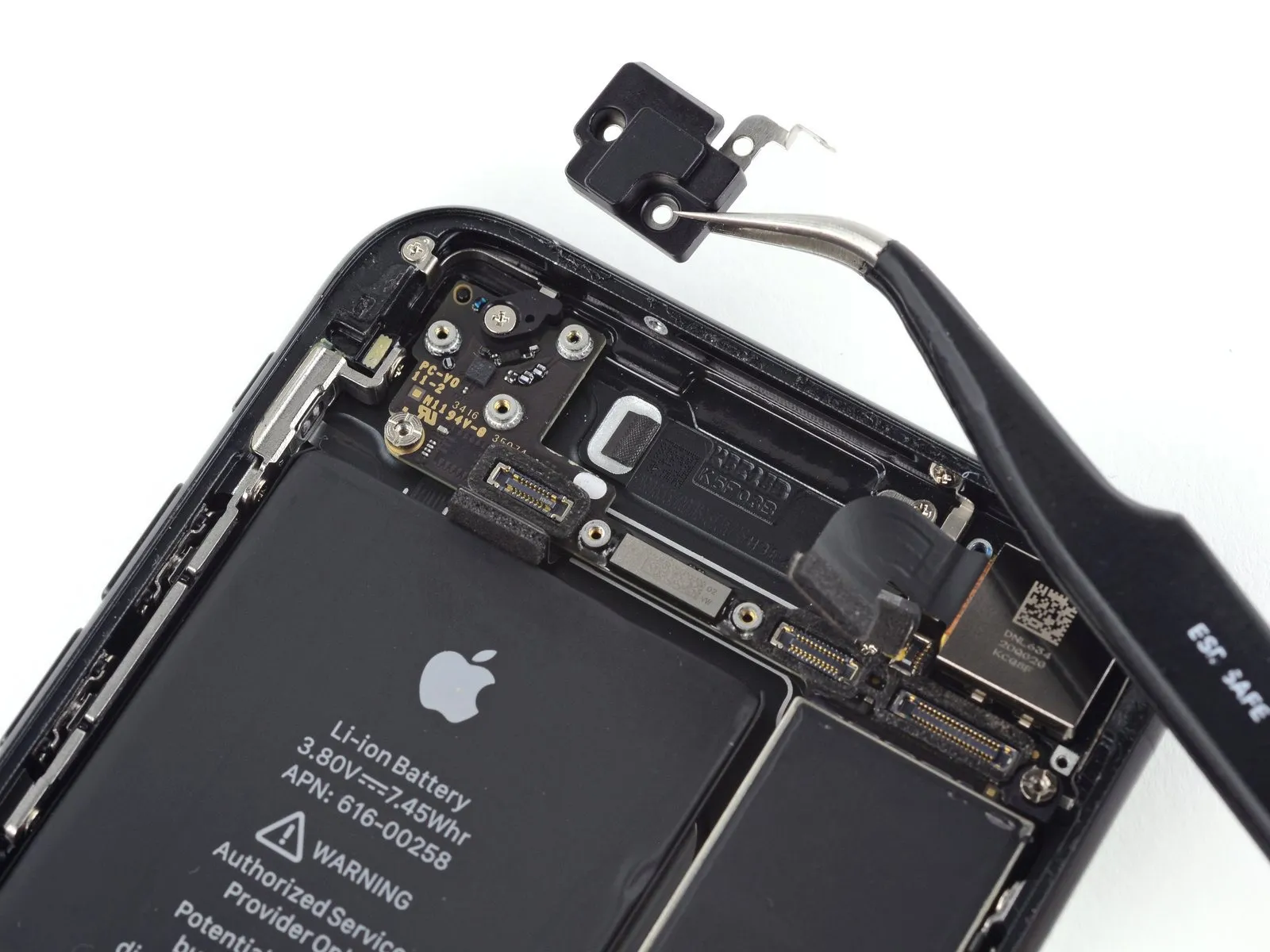
Step 23 | Barometric Vent
Step 24
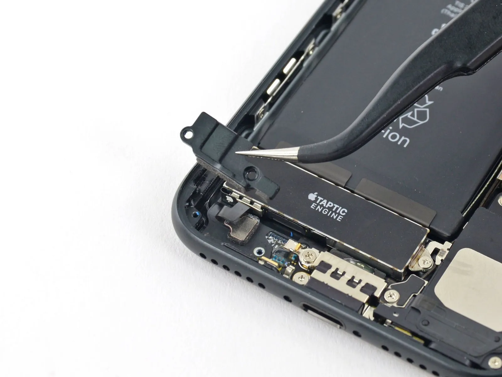
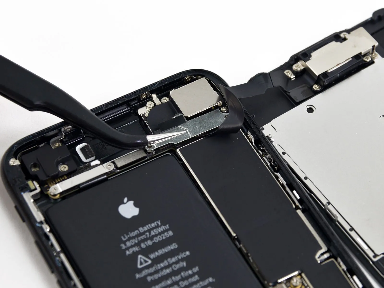
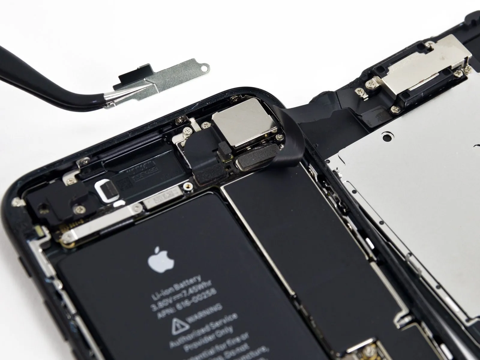
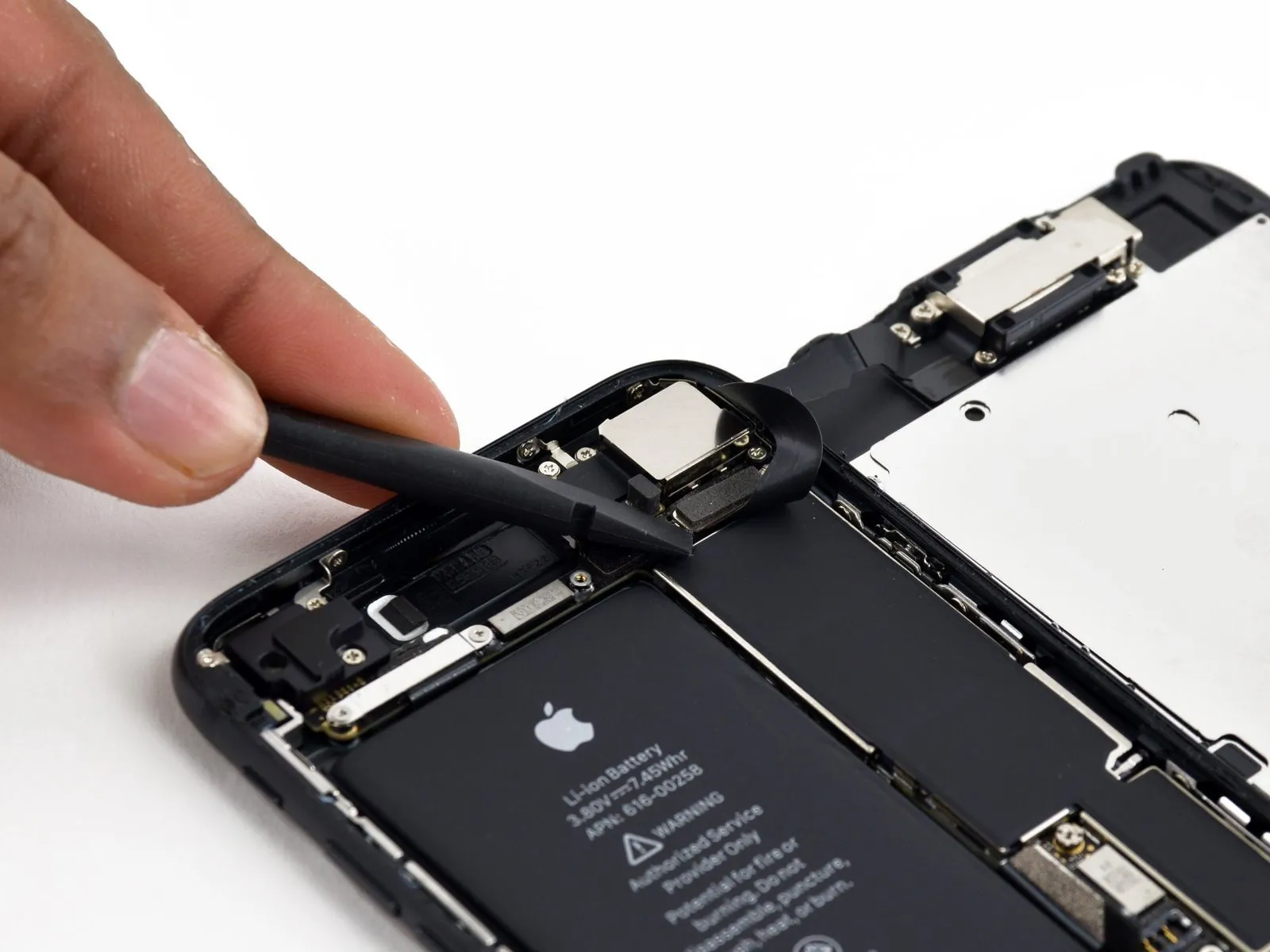
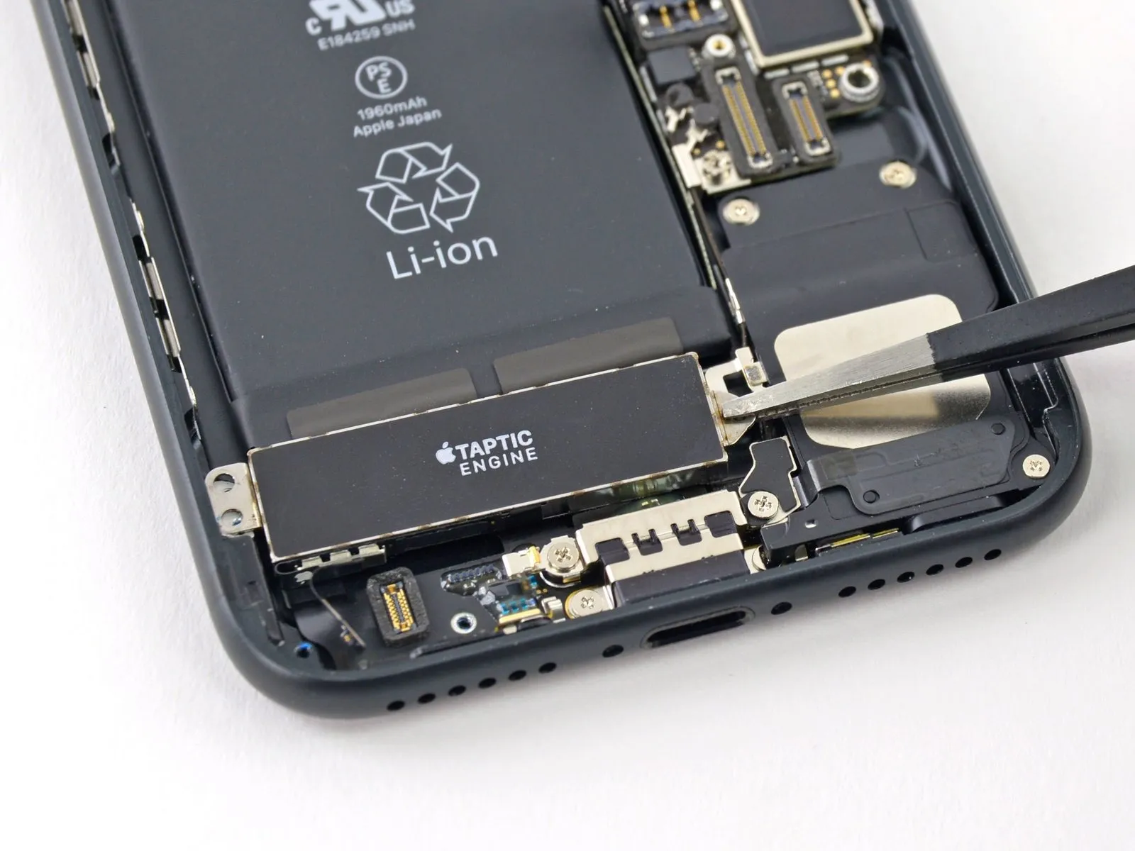
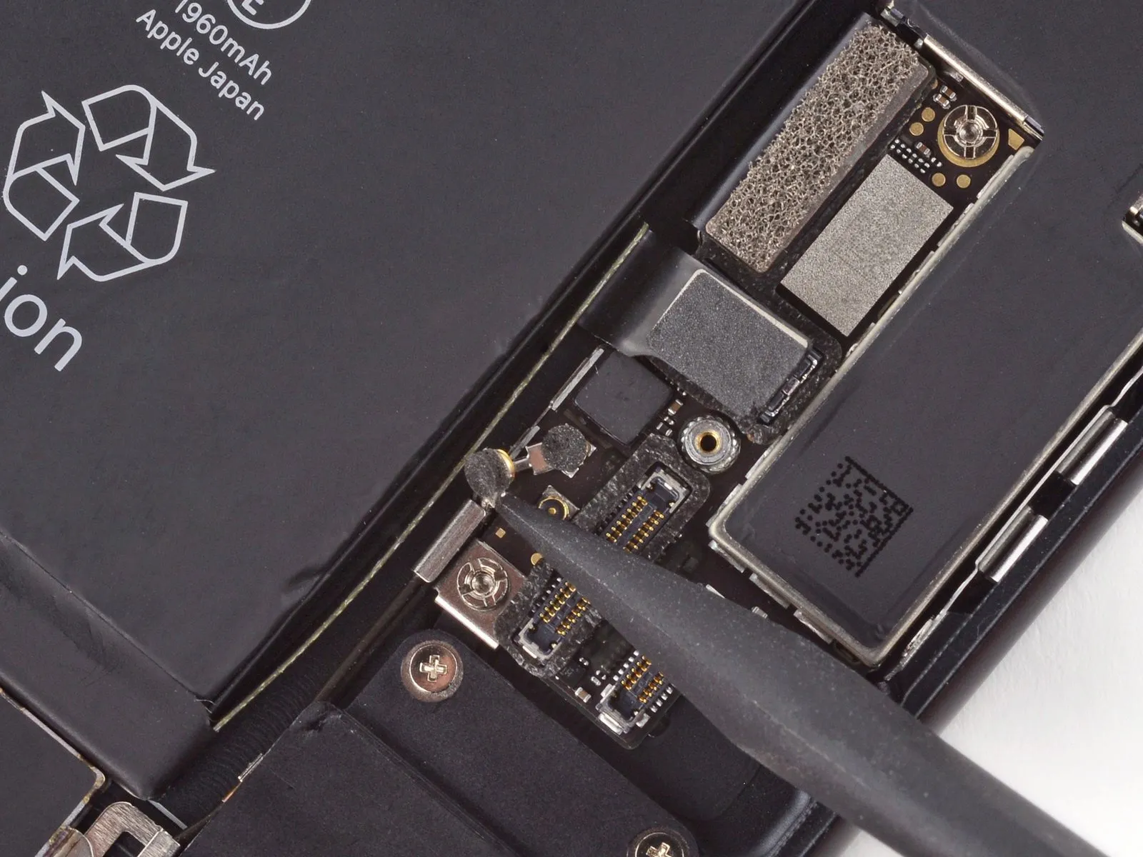
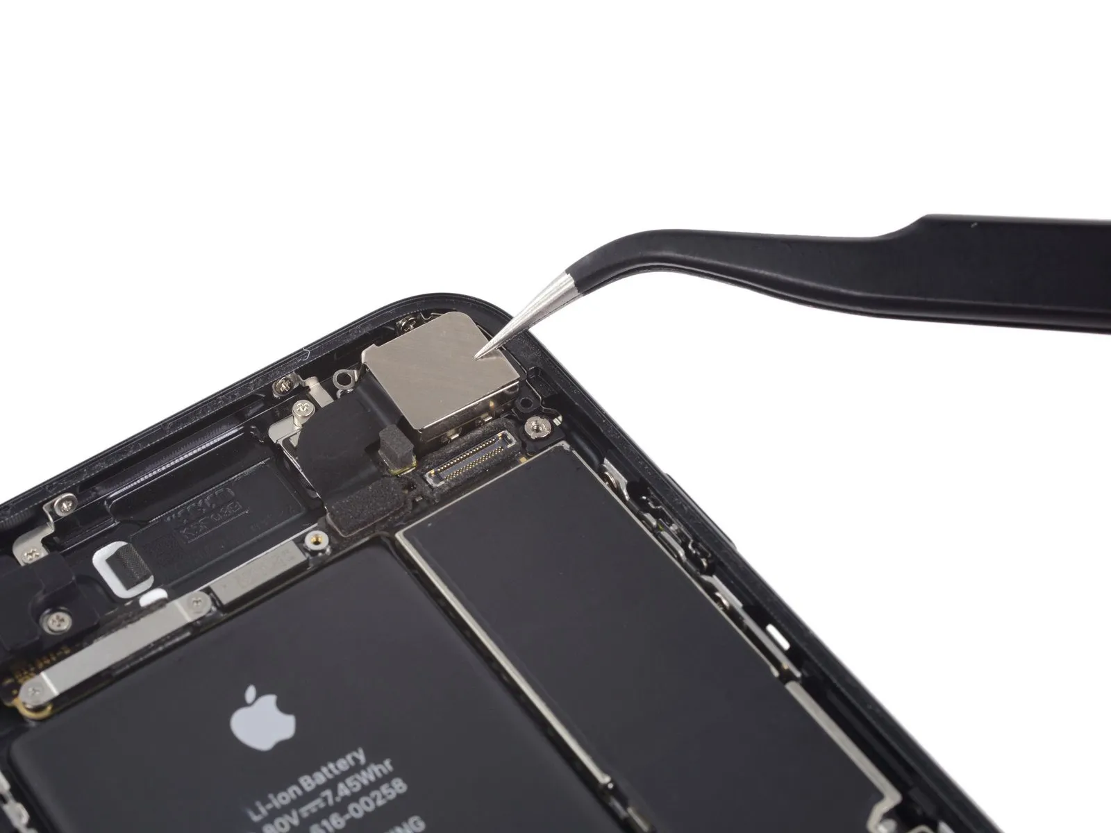
Step 25 | Taptic Engine
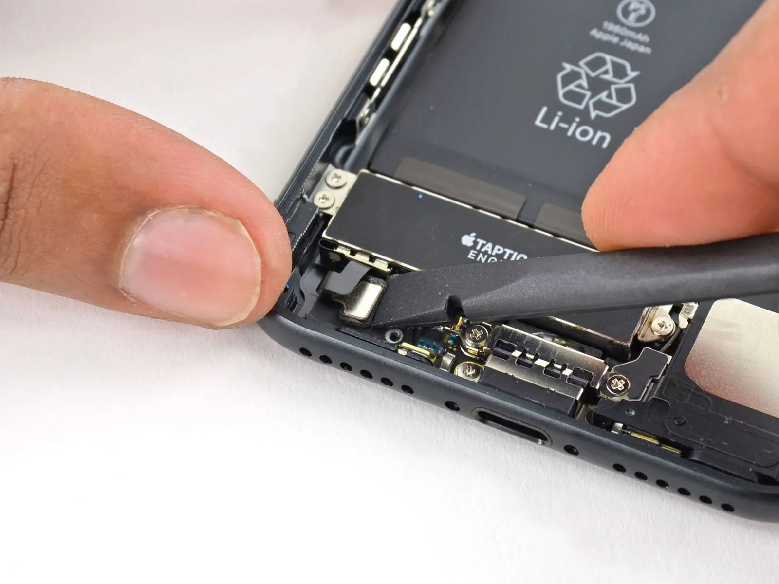
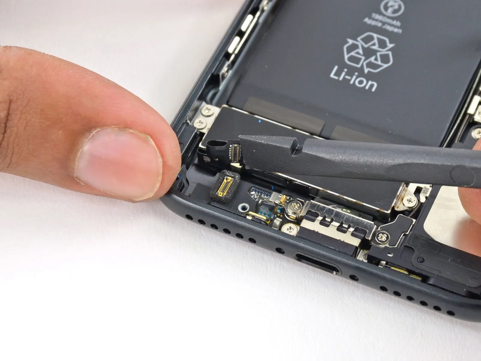
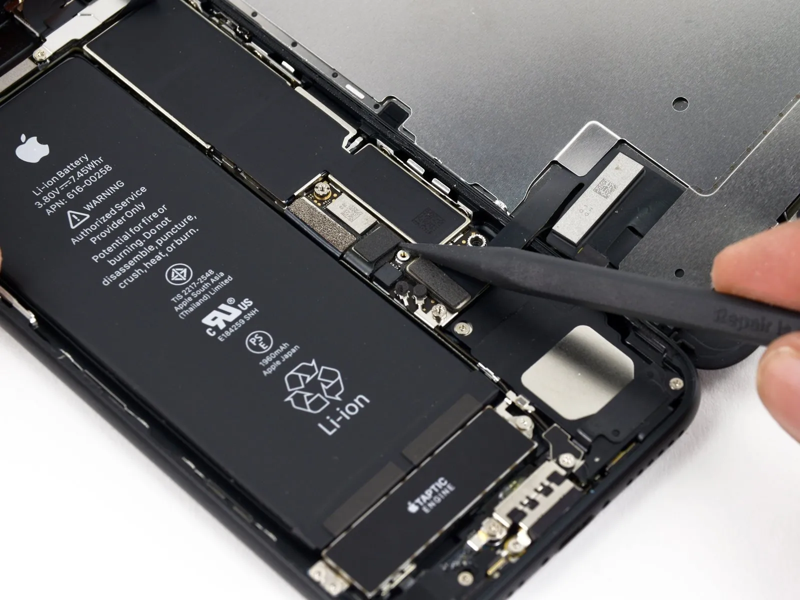
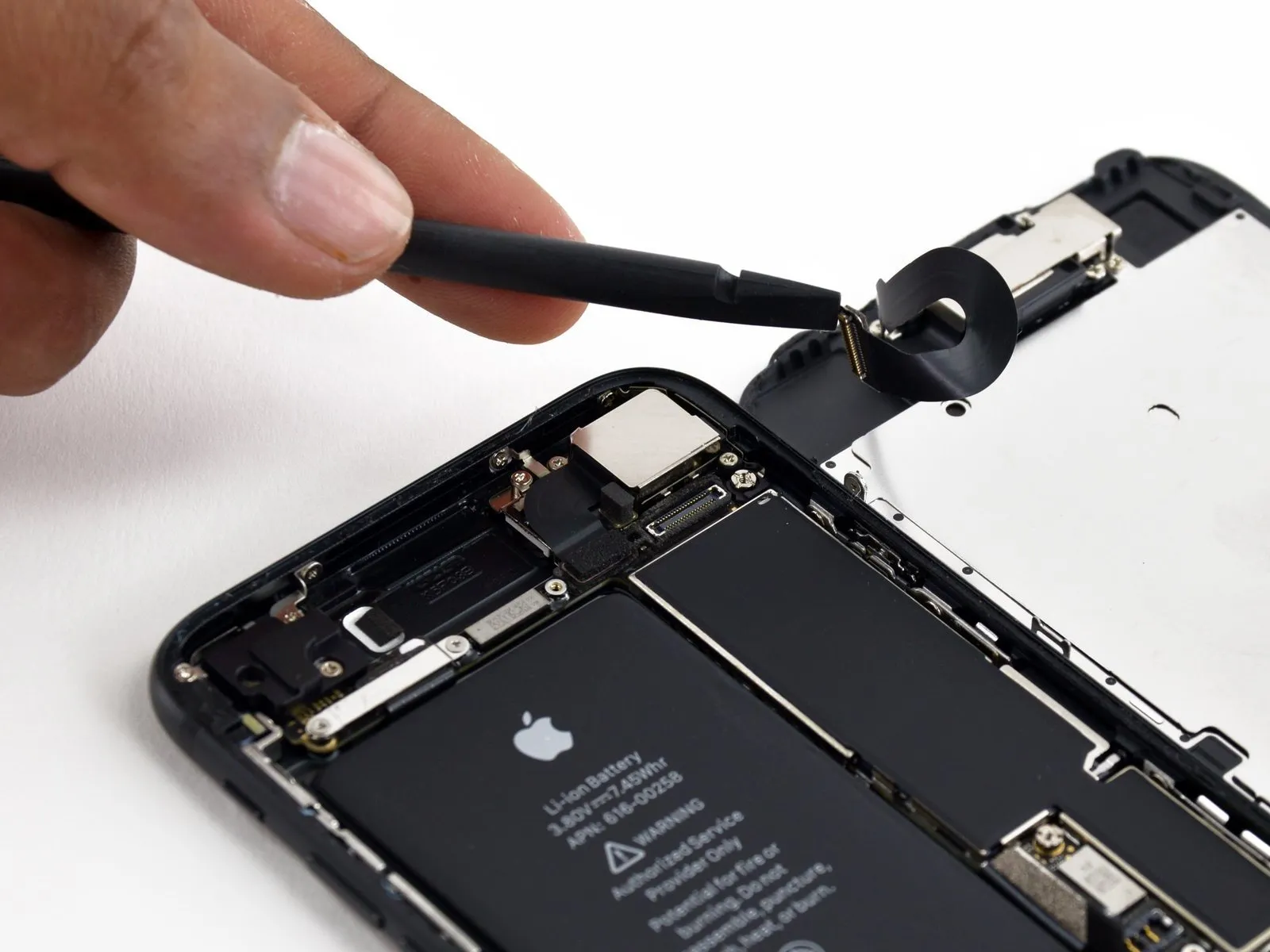
Employ the tool's planar edge.Use a plastic pry tool, often referred to as a spudger.Carefully separate the Taptic Engine connector from the corresponding socket on the logic board.
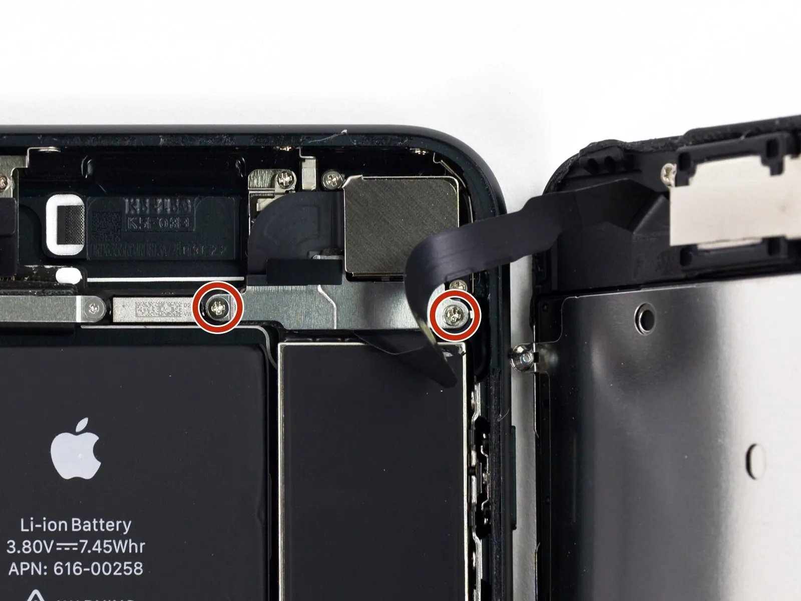
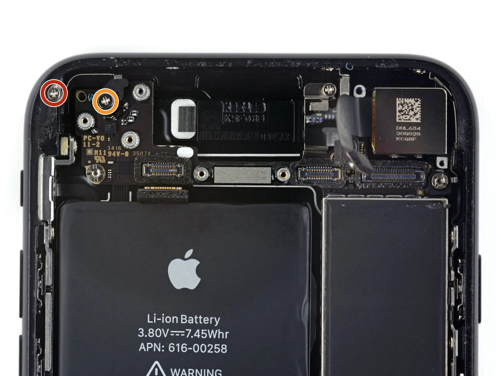
Step 26
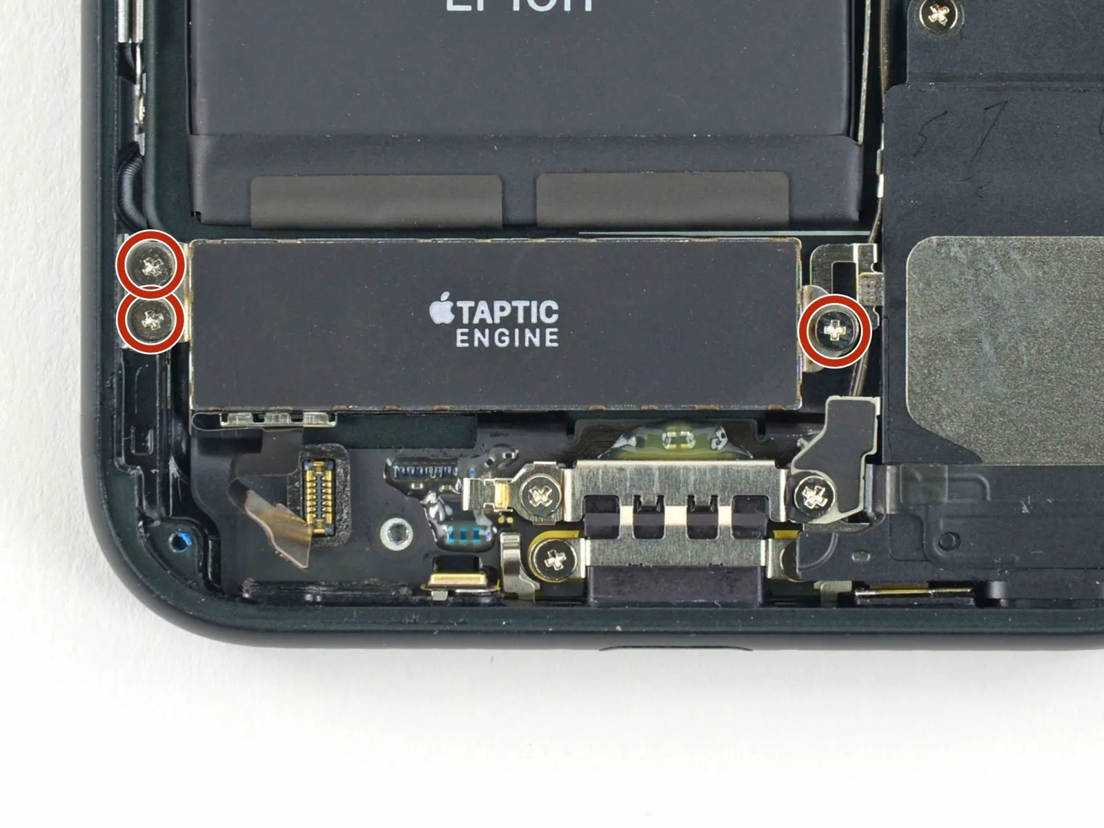
- Using the appropriate tool, detach the three.Use a Phillips screwdriver with a 1.6 mm tip.Affix the Taptic Engine to the rear case using the specified screws, ensuring proper alignment and torque as detailed in the service manual.
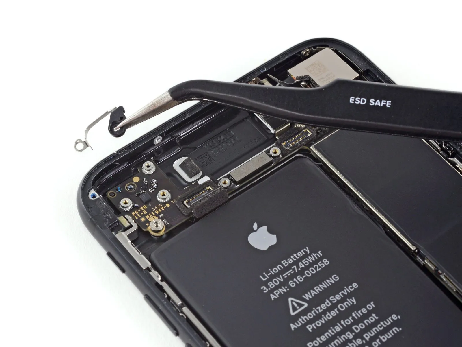
Step 27
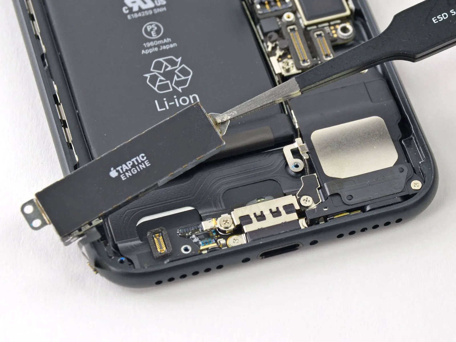
Carefully detach the Taptic Engine, ensuring no damage occurs.
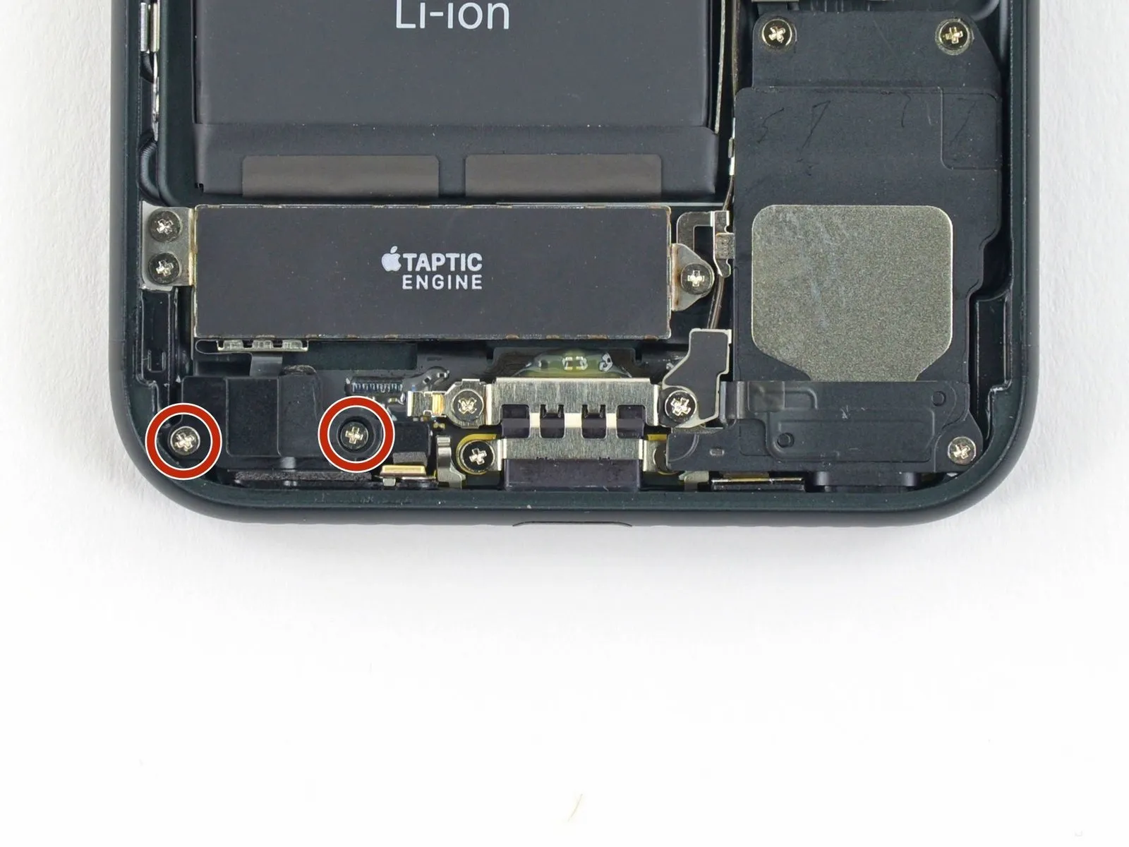
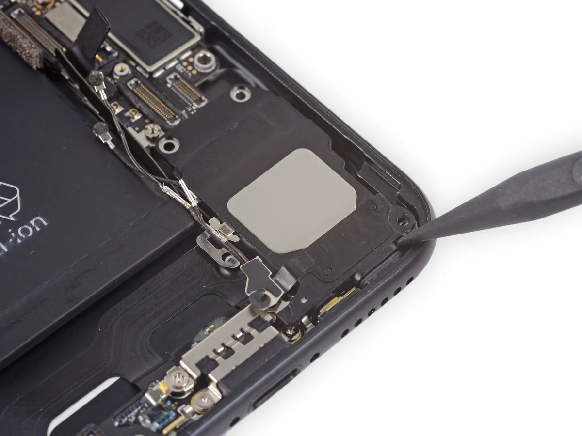
Step 28 | Speaker Assembly
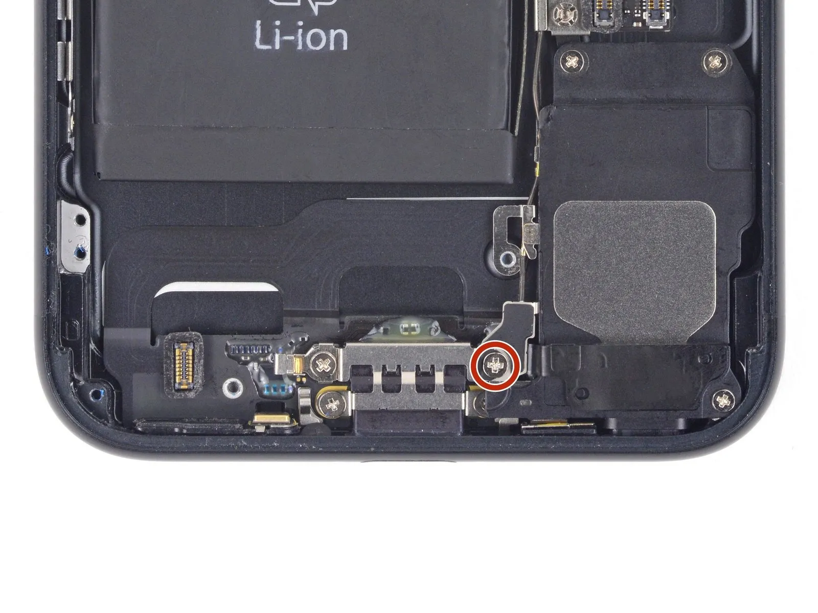
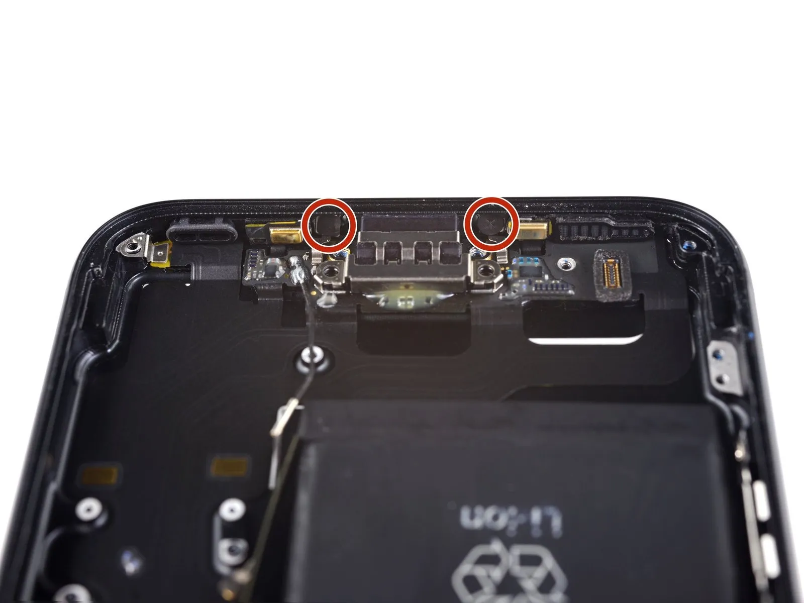
- Carefully detach the component, ensuring all associated fasteners are released and any specified measurements or numerical values are adhered to, utilizing the appropriate tools and observing all safety precautions and part names.Employ a Phillips head screwdriver to engage the fastener.Attach the Wi-Fi diversity antenna to the rear case, ensuring it's firmly fastened.
A single screw, measuring 3.2 millimeters, is required.
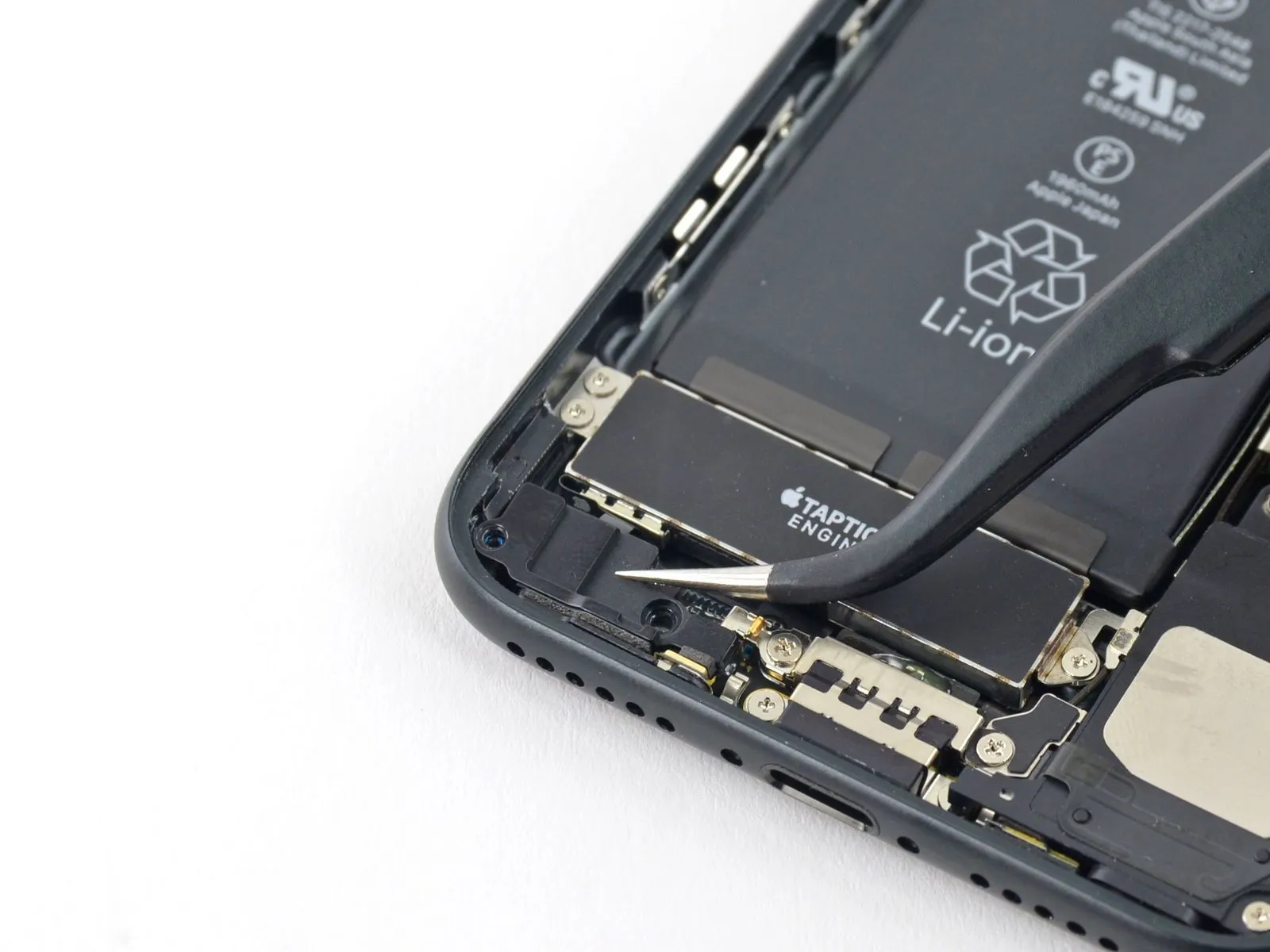
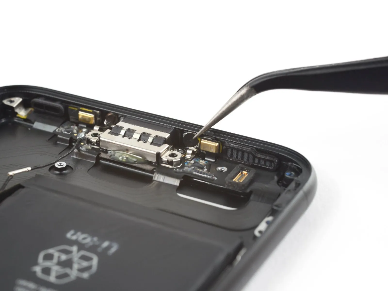
Step 29
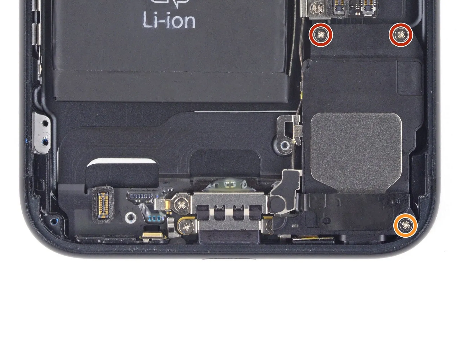
- Detach the component using appropriate tools, ensuring no damage occurs during the process.Employ these subsequent three.Use a Phillips head screwdriver.Using the provided M4x12 screws, fasten the speaker to the rear case, ensuring proper alignment.
Use two screws, each measuring 1.3 millimeters.
A screw with a 2.0 mm diameter is required.
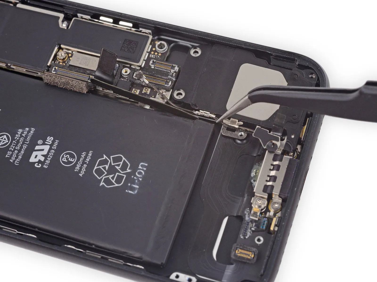
Step 30


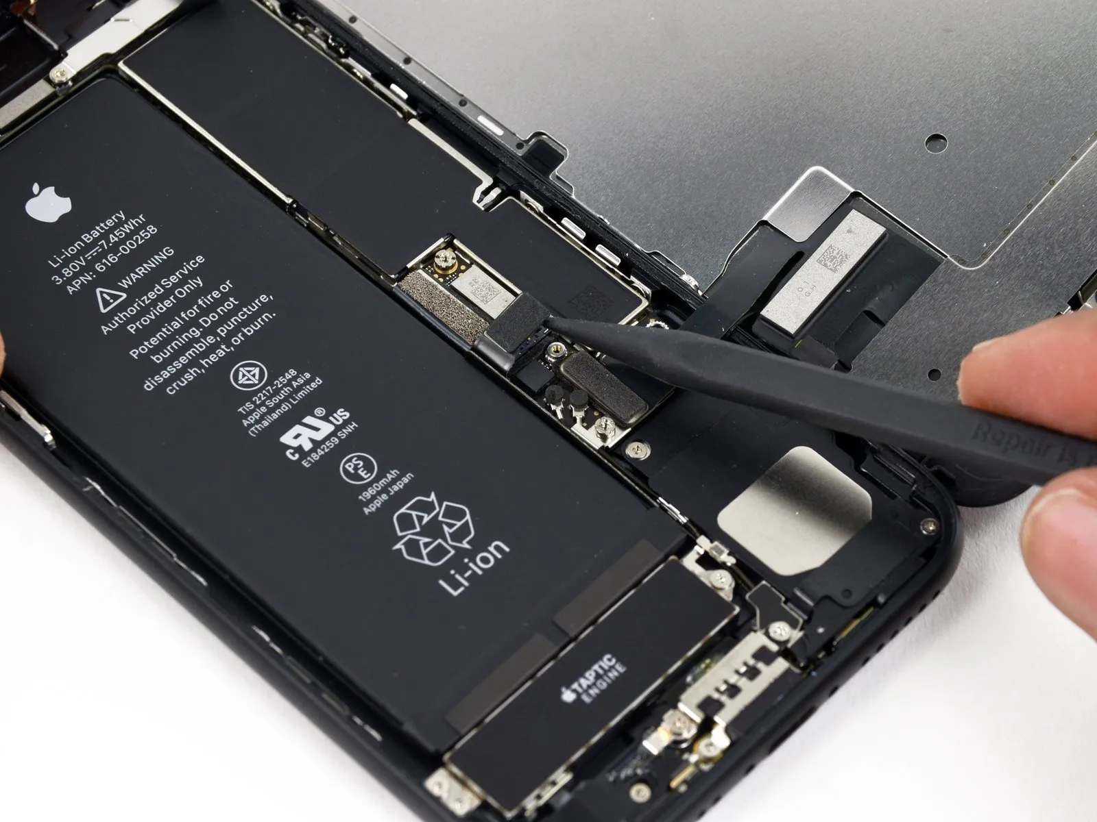
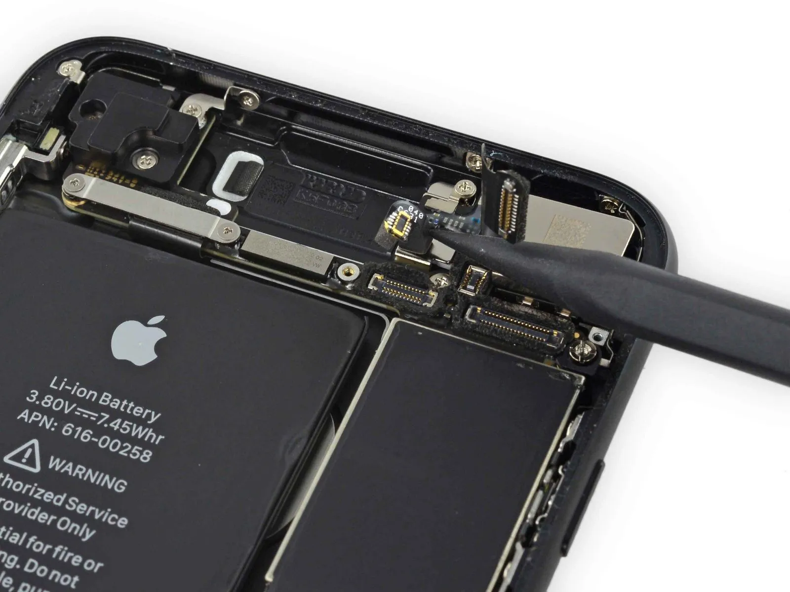
Employ the specified tool to perform the action.Ensure the tip is sharpened to a precise angle of 90 degrees, utilizing a honing guide and fine-grit sharpening stone, while exercising caution to avoid excessive pressure that could damage the tool's temper.Use a plastic pry tool, often referred to as a spudger, to gently separate components.Carefully raise the two antenna cable connectors to detach them from their corresponding sockets on the logic board.
Step 31

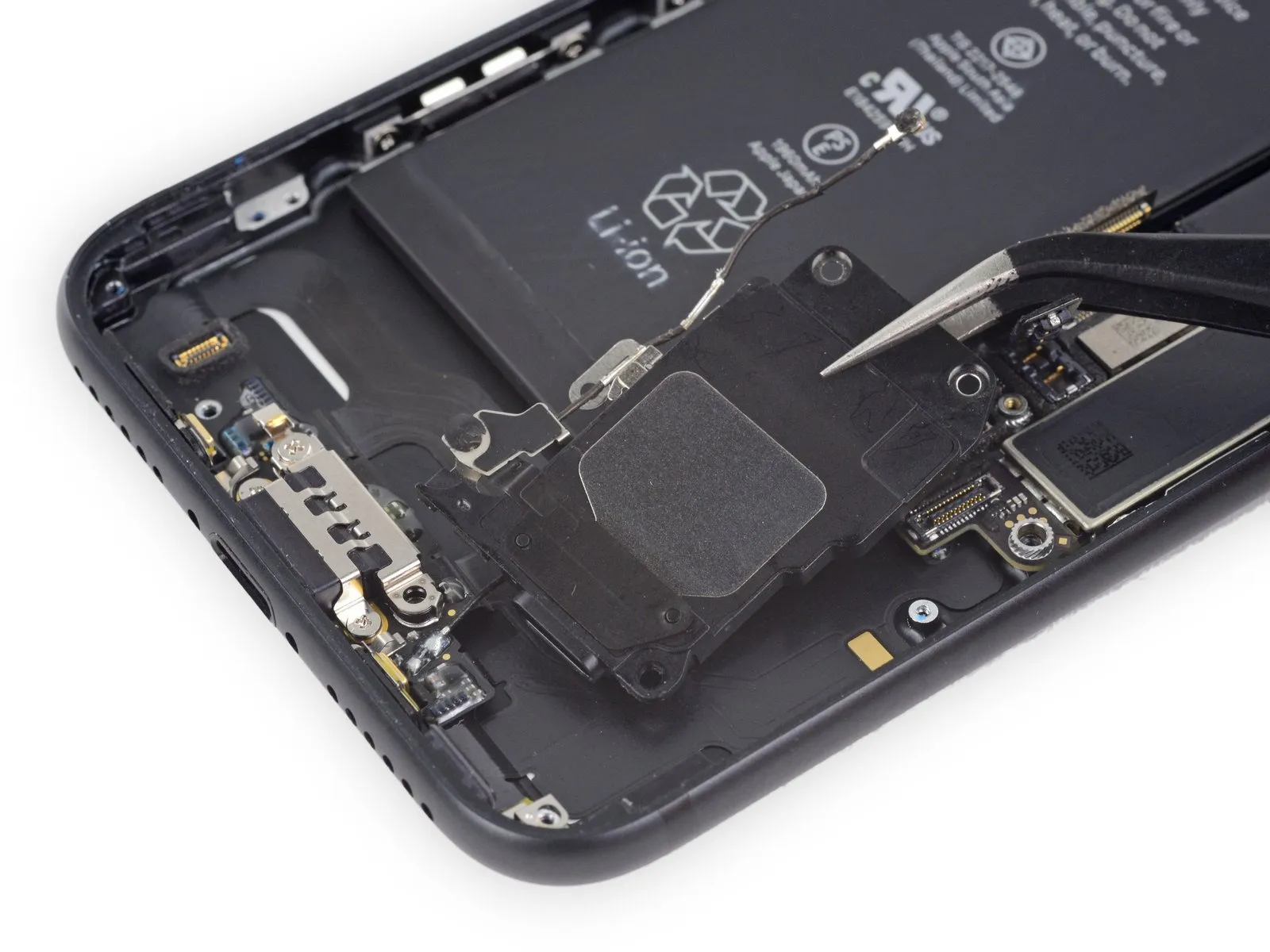
Employ the specified tool to perform the action.Using tweezers, carefully disengage the antenna cables from their securing bracket on the logic board.
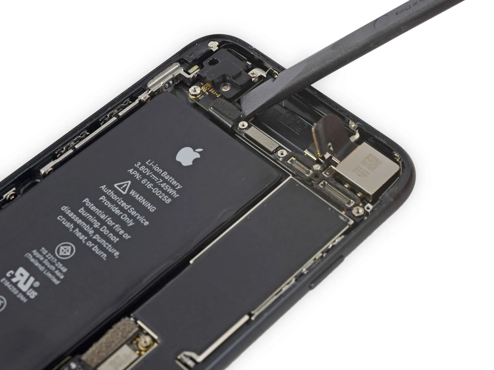
Step 32

- Employ the specified tool to apply force, ensuring a consistent pressure of 1.5 Newton-meters, and tighten the M4 screw securing the sensor assembly.Using tweezers, carefully detach the antenna cables from the speaker's clip.
Hold the cable firmly close to the clip.Exercise caution to prevent cable damage.
Step 33

Step 34
Step 35 | SIM Card
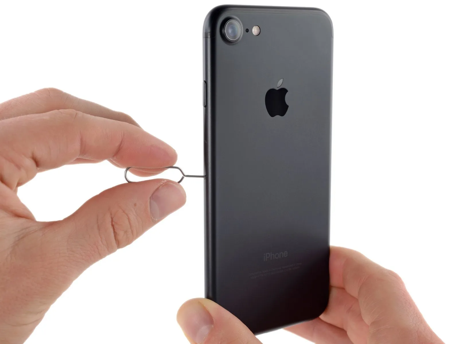
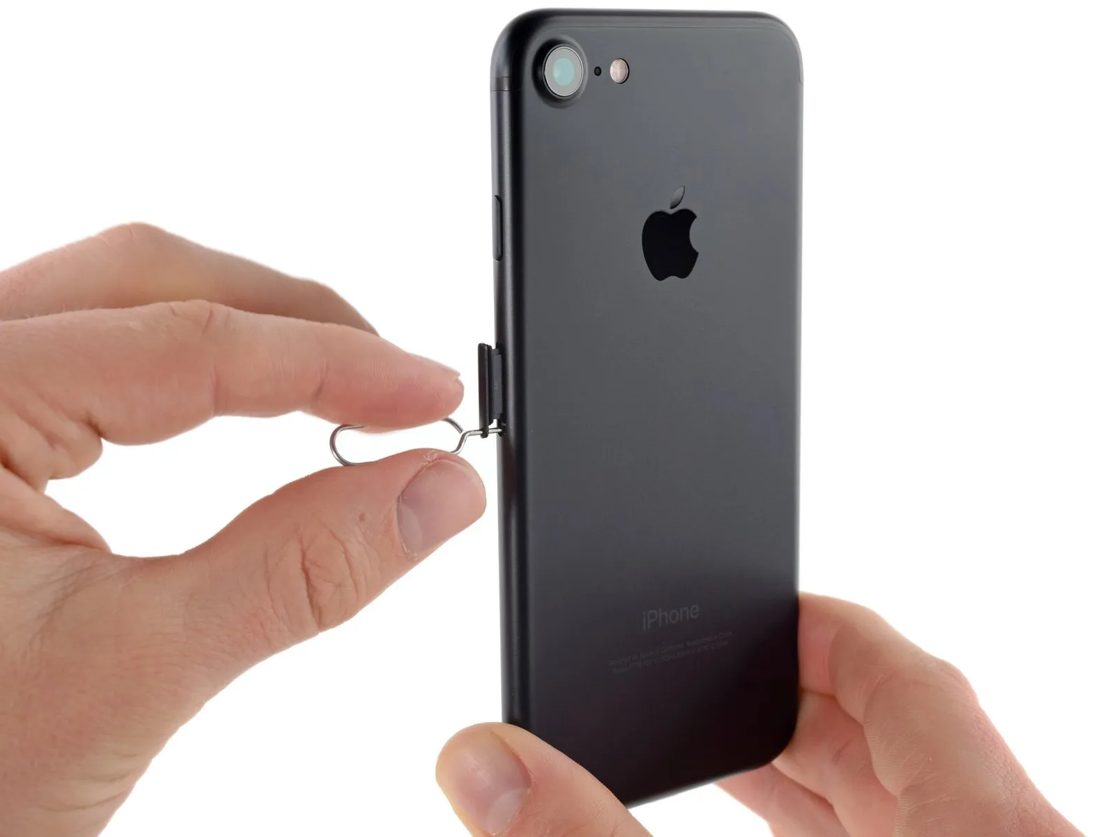

- Carefully position aUse the provided SIM card removal tool to release the SIM card tray.Use a paperclip, inserted into the small opening on the SIM card tray, to release it.
- To release the tray, apply firm pressure; excessive force may be necessary. Prior to applying pressure, carefully position the eject tool to prevent damage to the internal ejection components.
- Carefully detach theThe component responsible for housing and accessing the SIM card is the SIM card tray assembly.Retrieve the component from the iPhone.
- Confirm the SIM card's correct alignment within the tray before sliding it back in.
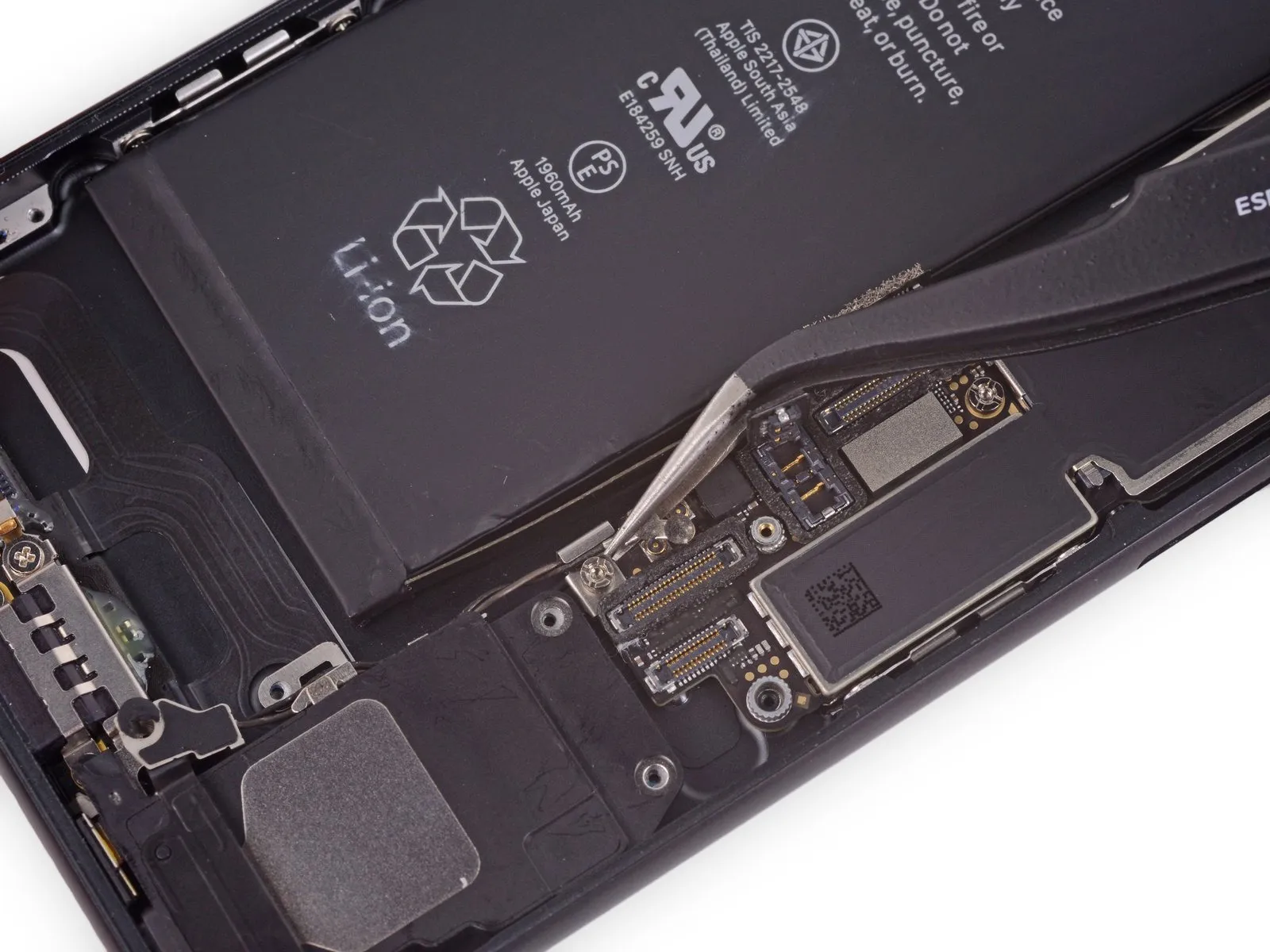
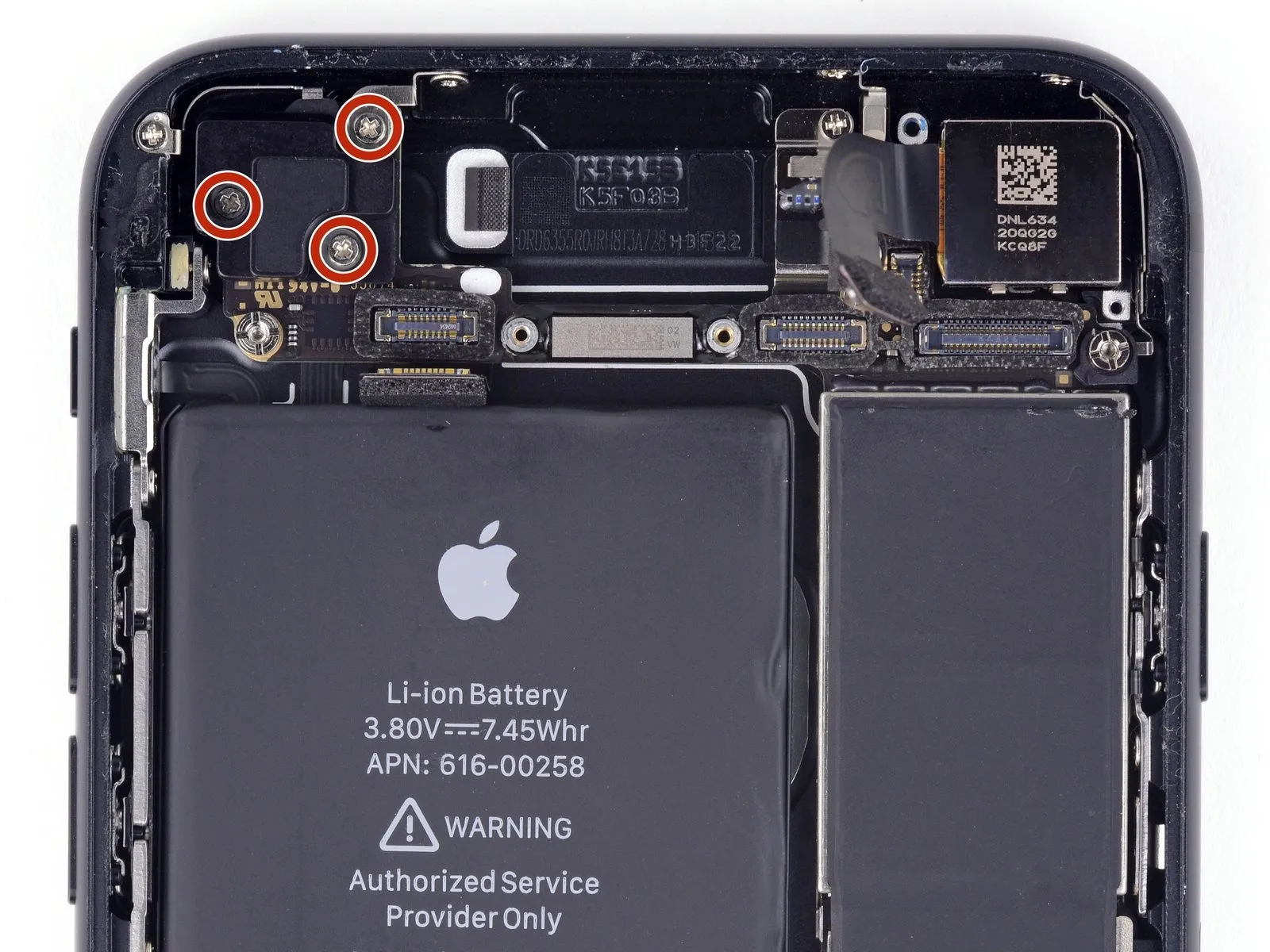
Step 36 | Logic Board Connectors
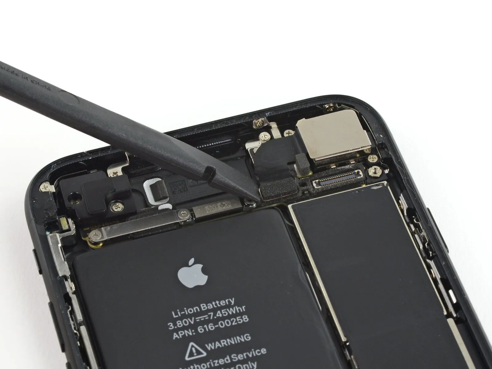

Step 37

- Detach the component.Employ a screw measuring 1.3 millimeters.
- Detach the component.A screw with a 2.5-millimeter diameter is required.
Step 38

Step 39

Step 40

Step 41


Step 42

Step 43
- Using the appropriate size screwdriver, detach the four screws.Use a Phillips head screwdriver.Carefully attach the Wi-Fi antenna, ensuring it is firmly connected and tightened to the specified torque of 8 in-lbs using a 4mm hex key, observing all safety precautions regarding static discharge.
- Use three screws, each measuring 1.2 millimeters.
- A screw with a 1.7-millimeter head diameter is required.
Step 44

Step 45
- Detach the listed components.Use a Phillips head screwdriver.:
A screw with a 1.3 mm head diameter is required.
A screw with a 2.2 mm head diameter is required.
Step 46

- Carefully detach the component, ensuring all original specifications—including dimensions, numerical values, required tools, safety precautions, and part designations—are adhered to during the process.Employ a fastener to secure the component..
Step 47
- Carefully detach the component, ensuring all original connections are released.Use a 2.2 mm screw to secure the standoff.Detach the bracket that provides the electrical ground.
Secure the component to the chassis using the provided standoff screws.Employ a standoff screwdriver or bit to detach these components.
If a dedicated tool isn't available, a small flathead screwdriver can be carefully substituted; however, exercise heightened awareness to prevent slippage and potential harm to nearby parts.
Step 48
- Employ the specified tool to perform the action.Employ fine-tipped pliers or similar precision instruments.Carefully deflect the logic board's grounding bracket, ensuring no forceful pressure is applied.
Step 49 | Lightning Connector Assembly
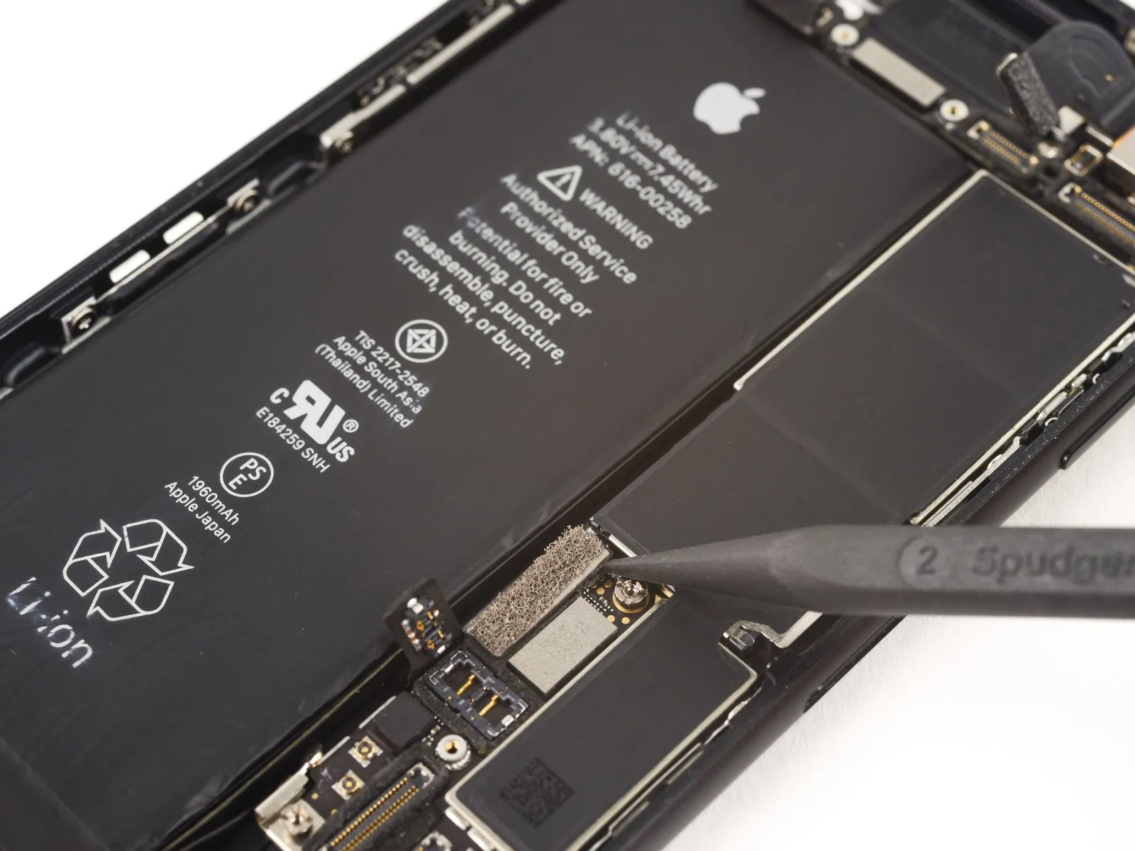

Step 50
- Begin the process by performing action one.Use a Phillips screwdriver with a 1.4 mm tip.
- Three.Use screws with a 2.2 mm thread diameter.
To detach standoff screws, utilize a screwdriver or bit specifically designed for standoffs.
If a dedicated tool isn't available, a small flathead screwdriver can be substituted; however, exercise heightened care to prevent slippage and potential harm to nearby parts.
Step 51

Step 52


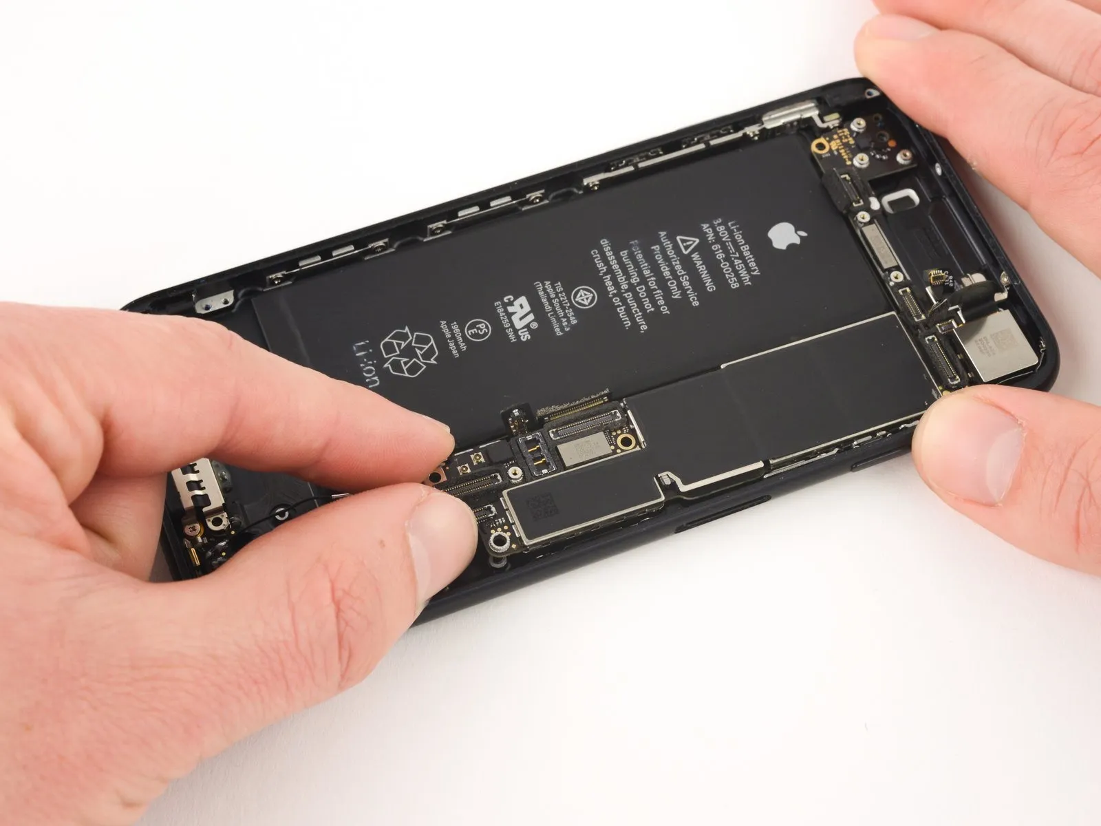
- Carefully raise the logic board's battery connector section by applying gentle upward pressure with the spudger's flat tip.
Before proceeding, verify that no wires are being strained. Any encountered opposition indicates a need to inspect all cables, connectors, and components to ensure they are free from obstructions on the circuit board.
Step 53

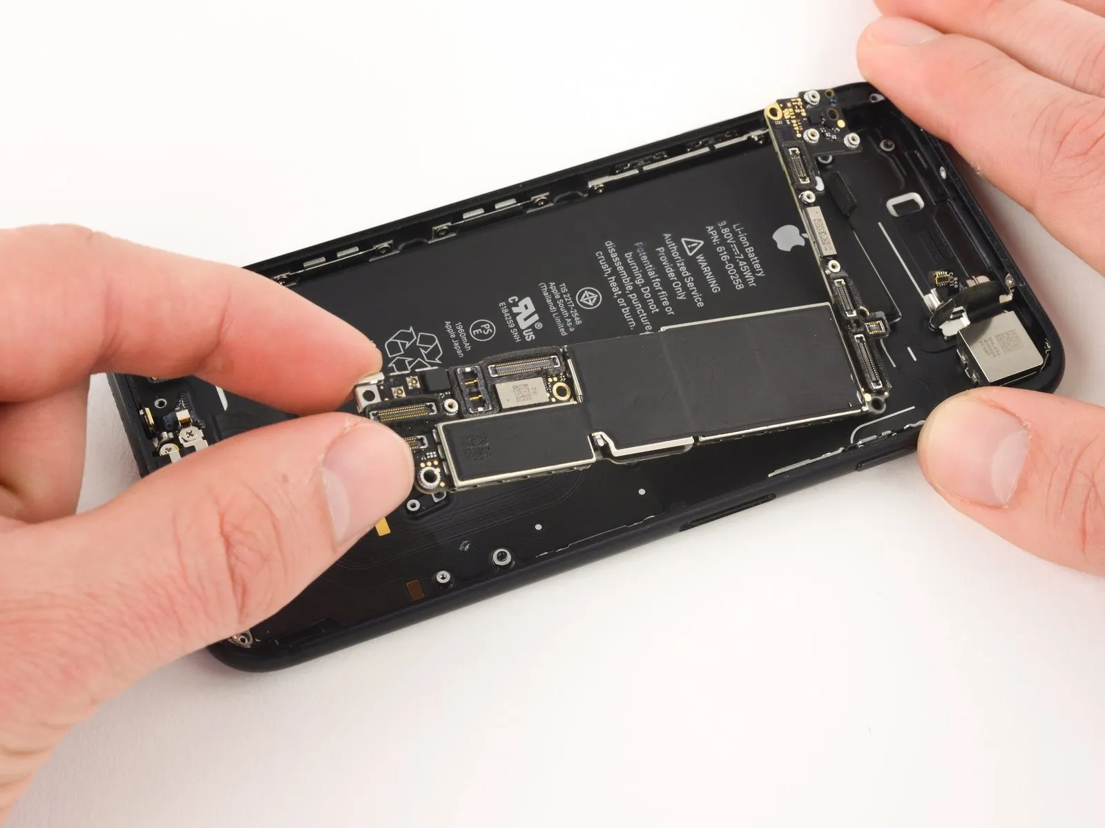
- Carefully raise the logic board’s battery connector to disengage it, then slide the board upwards and away from the rear case.
- Exercise caution to prevent the logic board from being damaged by contact with any wires.
Step 54

Step 55

Step 56
Step 57

Step 58

Step 59

Step 60

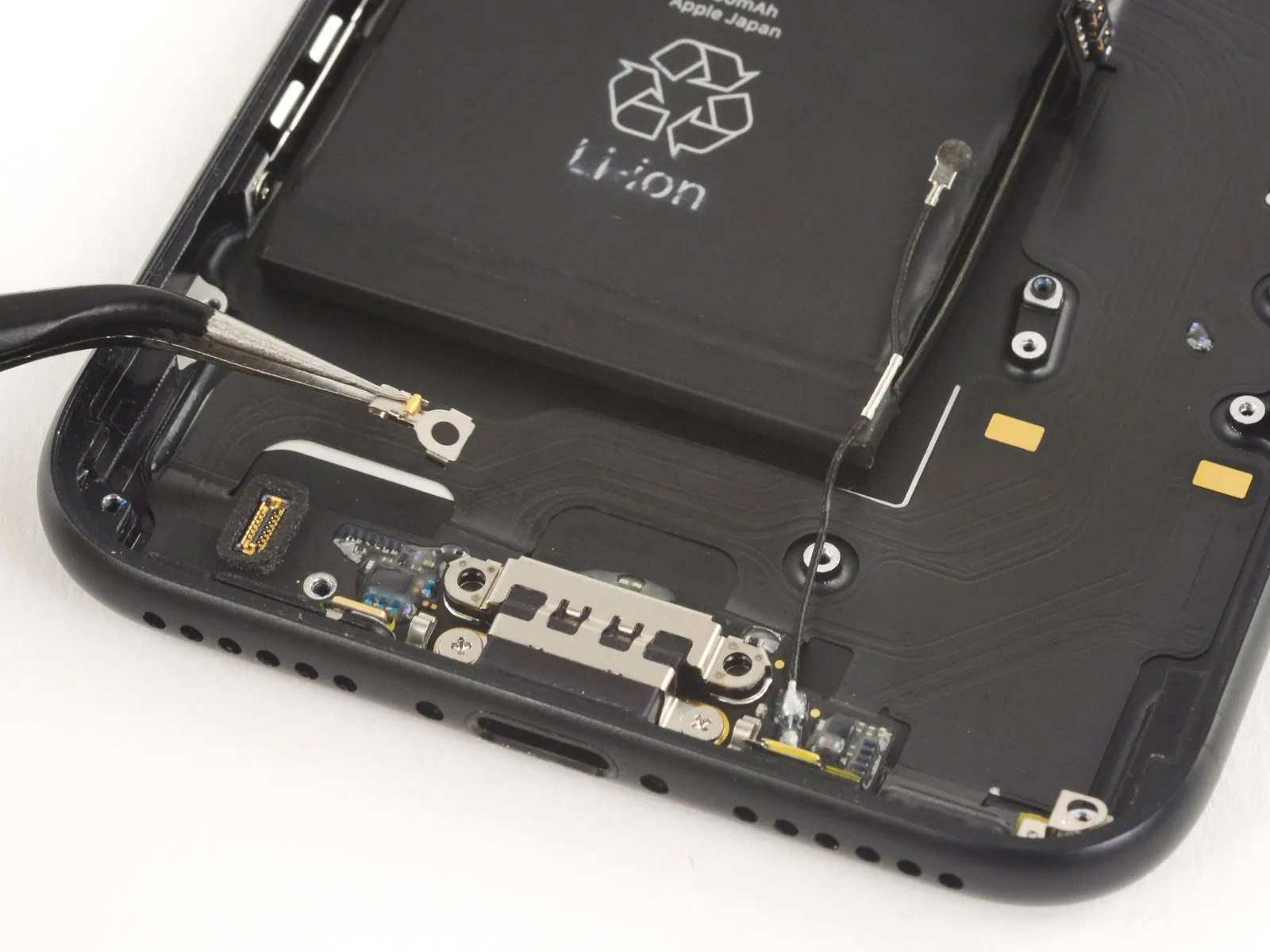
- Applying heat to the iPhone's bottom edge will loosen the adhesive that holds the Lightning connector cable in place, facilitating its removal.
- Apply warmth to the phone's bottom edge using a hairdryer or your iOpener heating pad.
- Give the adhesive approximately one minute to reach operating temperature before continuing.
Step 61
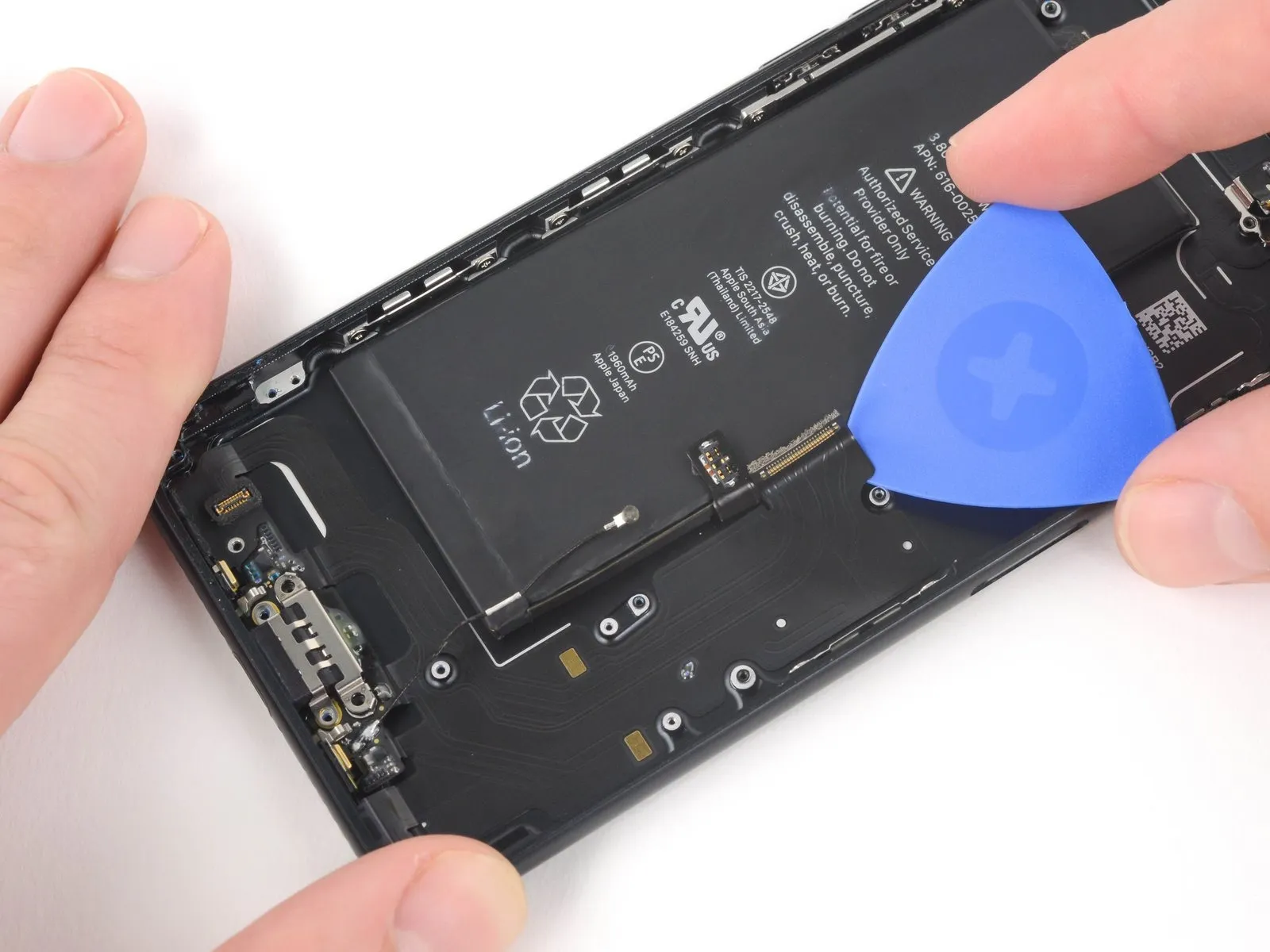
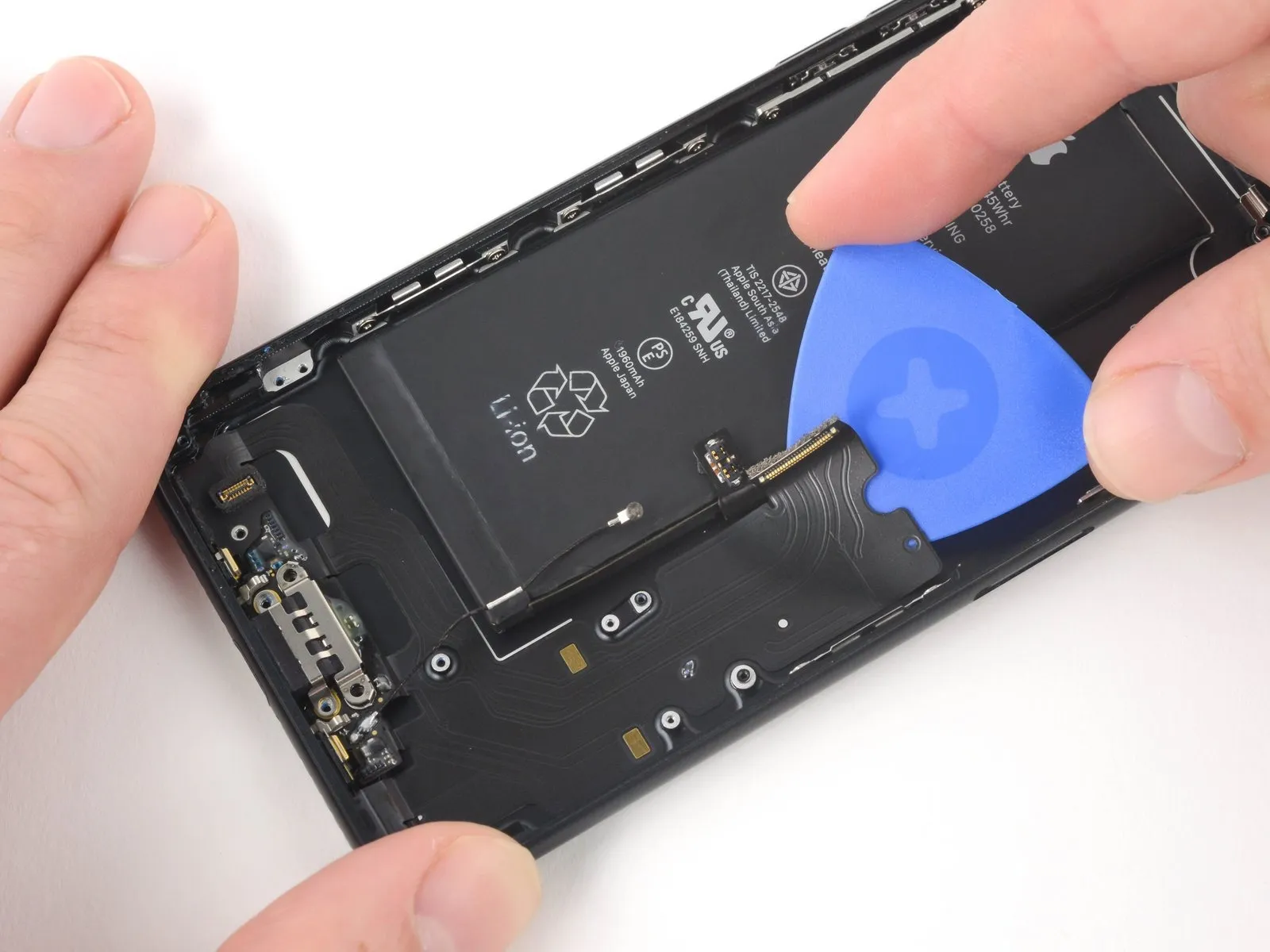
Beginning at the phone's center point, carefully insert an opening pick to separate the adhesive securing the display assembly.USB-C connectorCarefully detach the component from the back housing.
Step 62
Advance the tool in a linear motion.USB-C connectorAdditional detachment from the rear case is required to facilitate disassembly.
Step 63

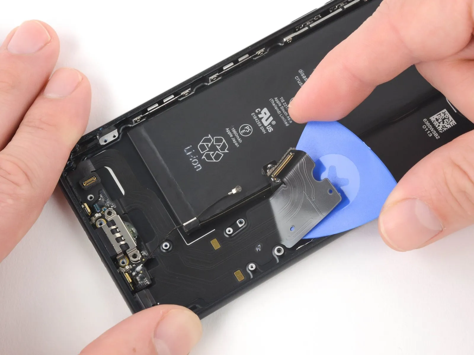
Carefully insert a pick beneath theThe connector, designed for use with Lightning cables, is an assembly.Cease the pick's forward movement immediately after it clears theCarefully disconnect the battery, observing proper polarity and ensuring no shorts occur, then safely remove it from the device, noting its voltage rating and physical dimensions for replacement with an equivalent unit..
Step 64
Beginning at a corner of the device, carefully insert the opening tool beneath the housing and gently maneuver it in the direction of the adjacent edge.USB-C connectorCease forward movement of the pick as it contacts the.USB-C connector.
Step 65

Step 66
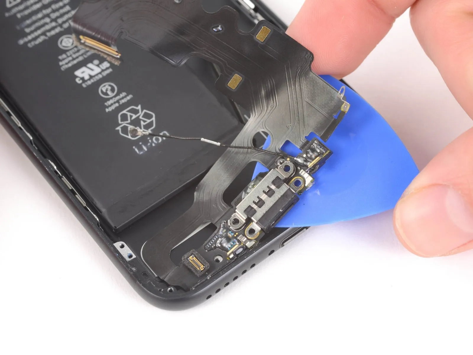

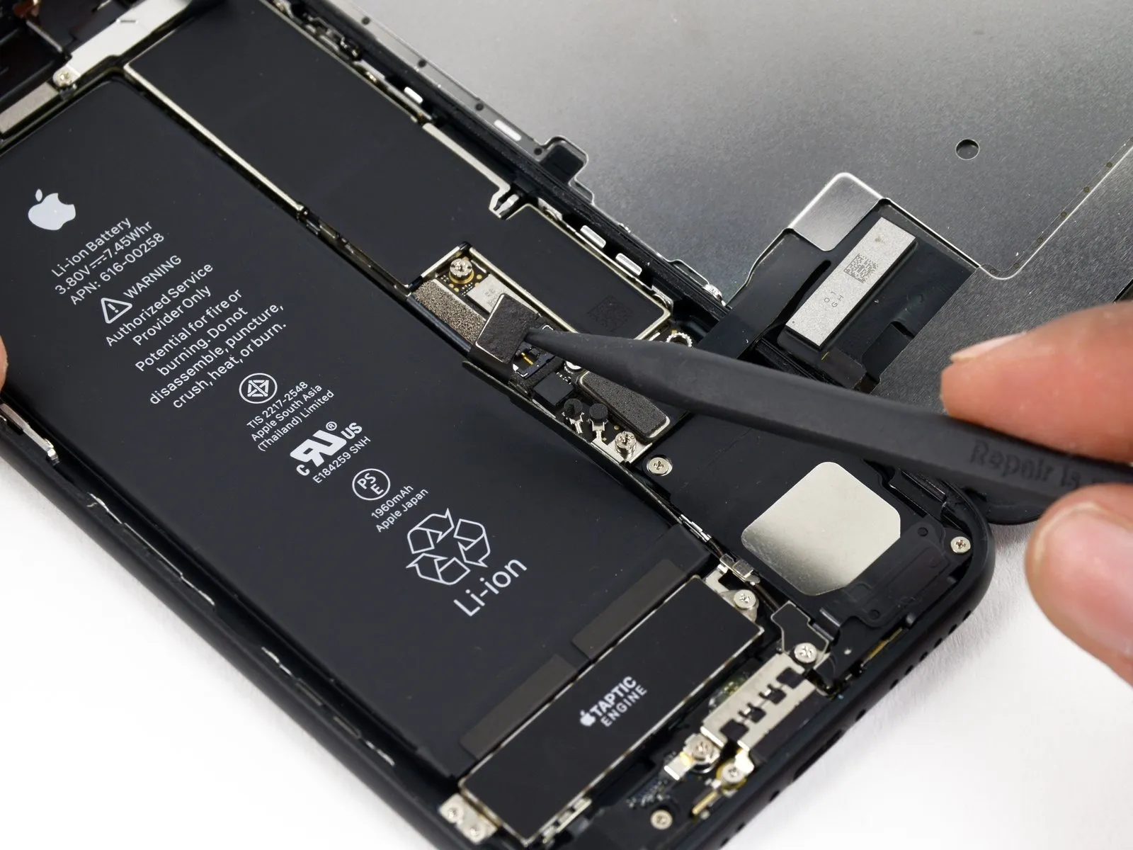
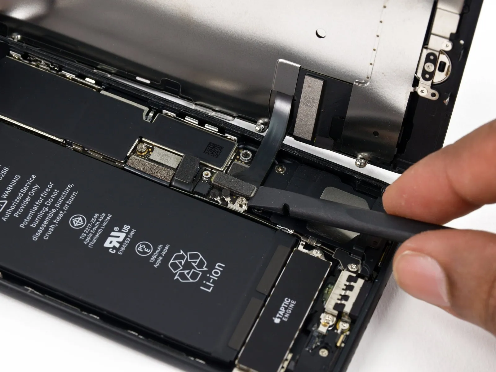
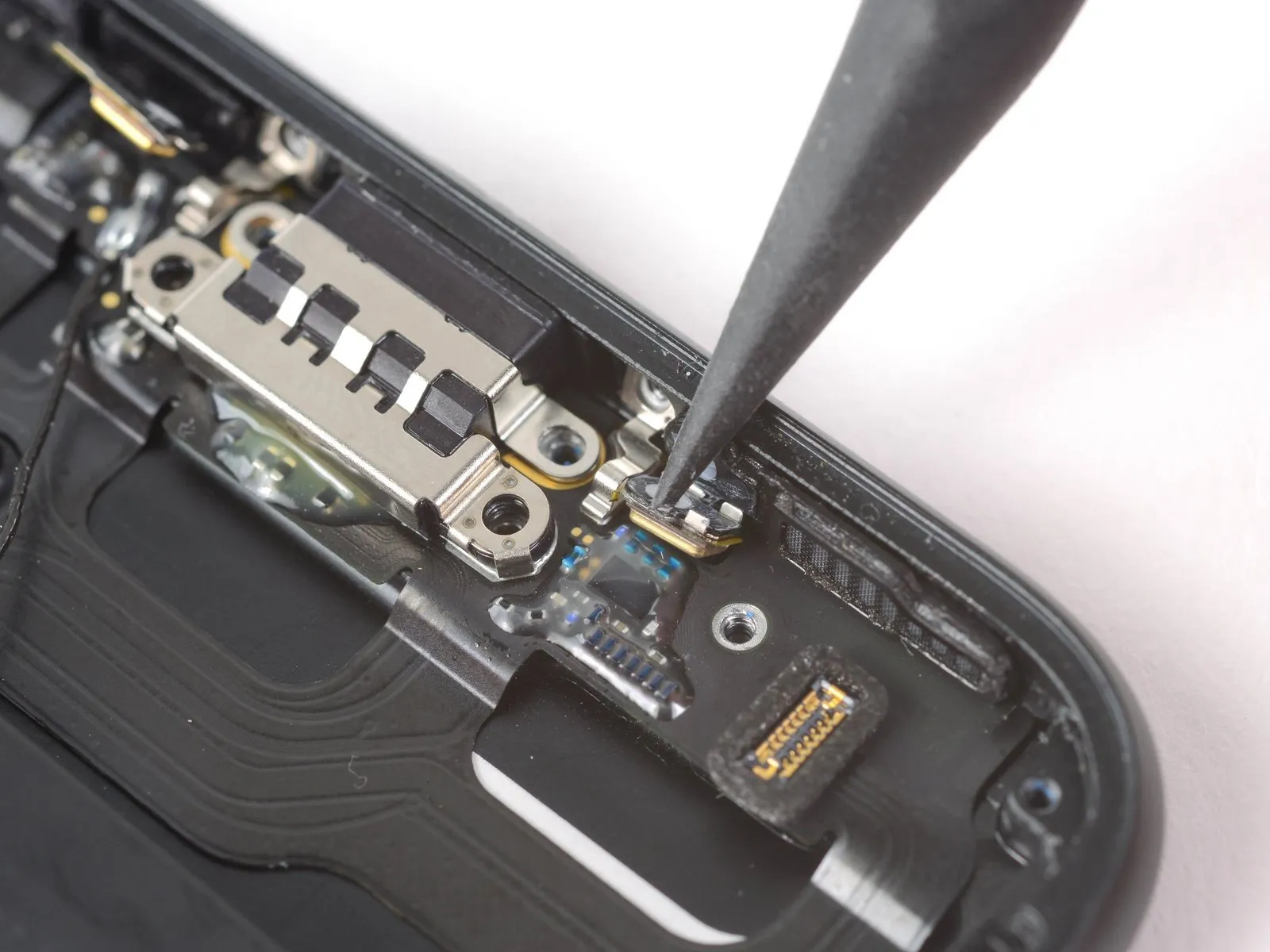
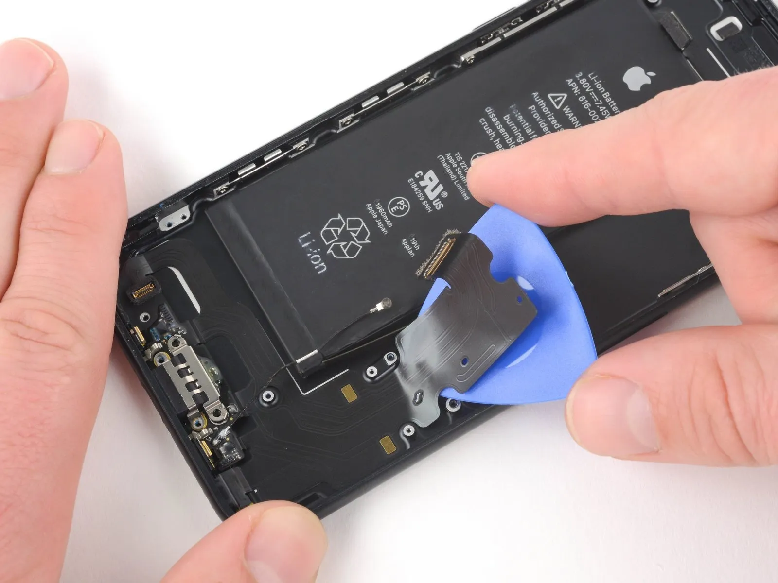
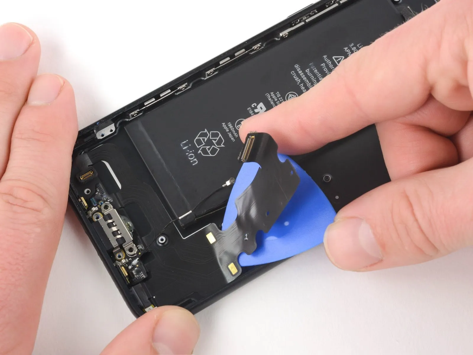
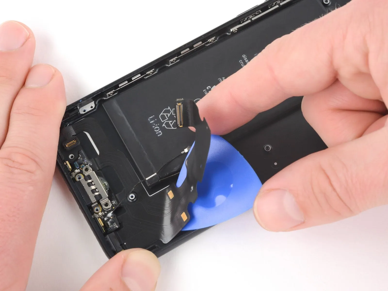
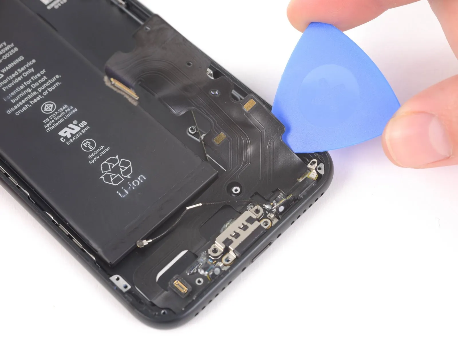
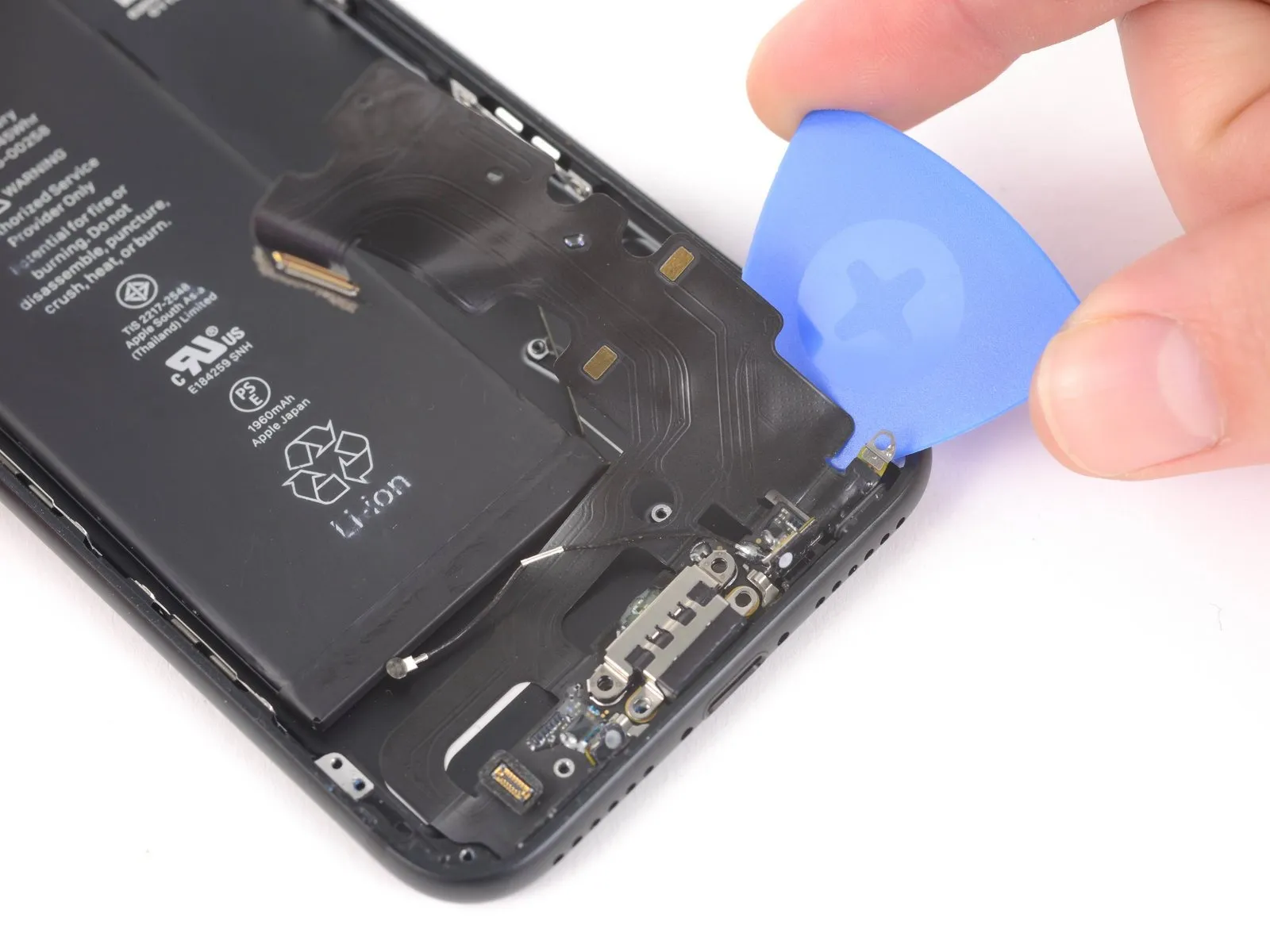
- Using a pick, gently work to create a gap between the lightning connector assembly and the rear case by inserting the pick beneath the lightning connector.
- Advance the prying tool until the lightning connector assembly releases from the back cover.
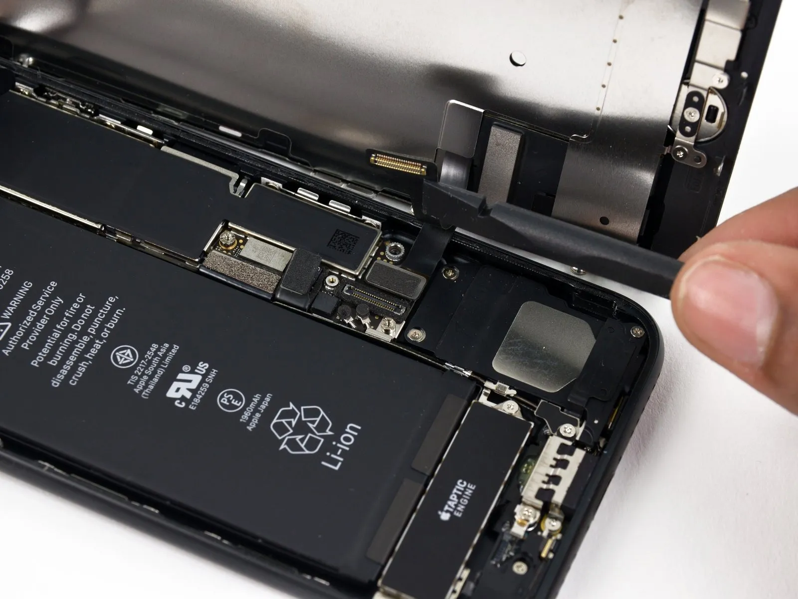
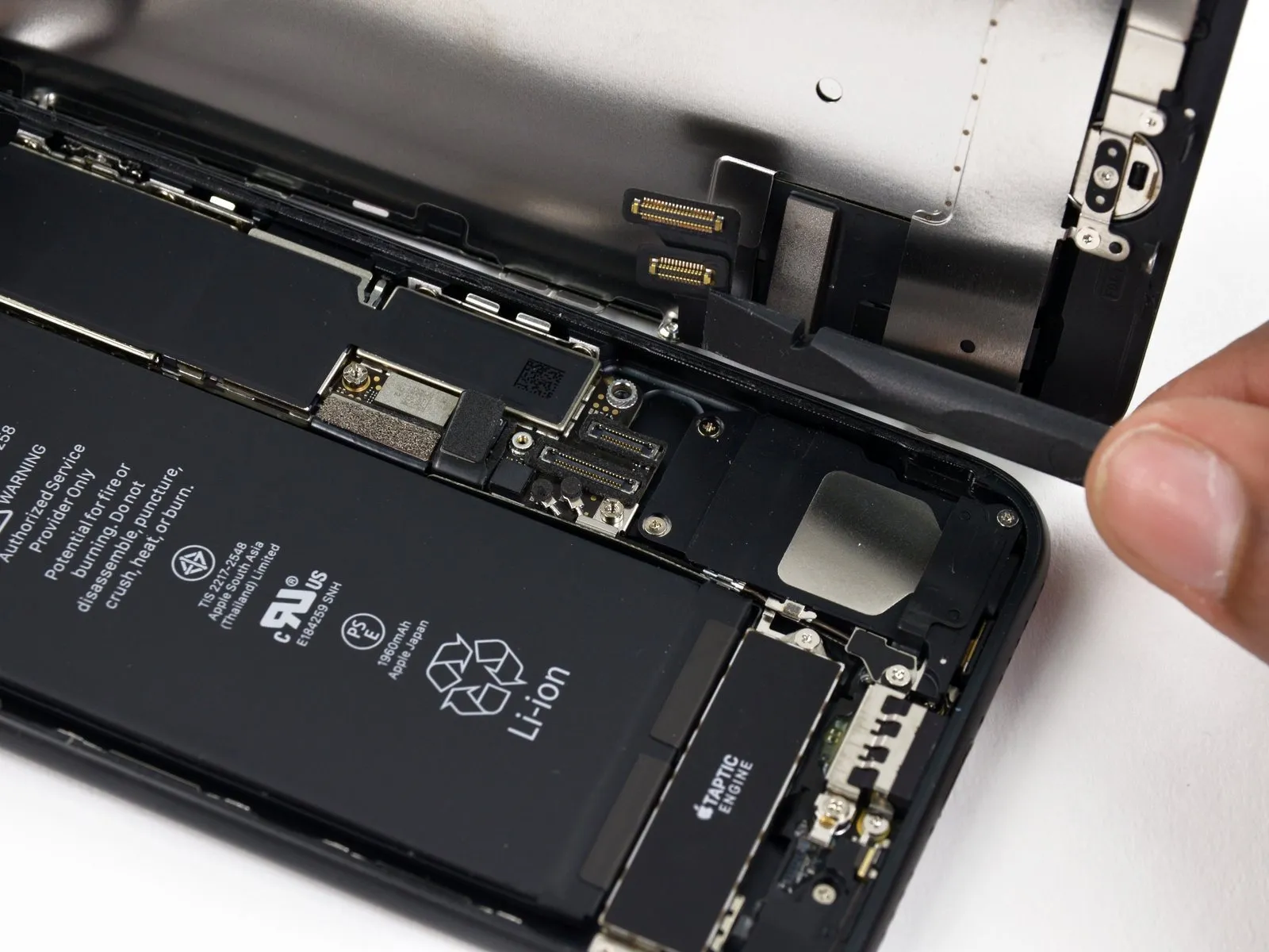
Step 67
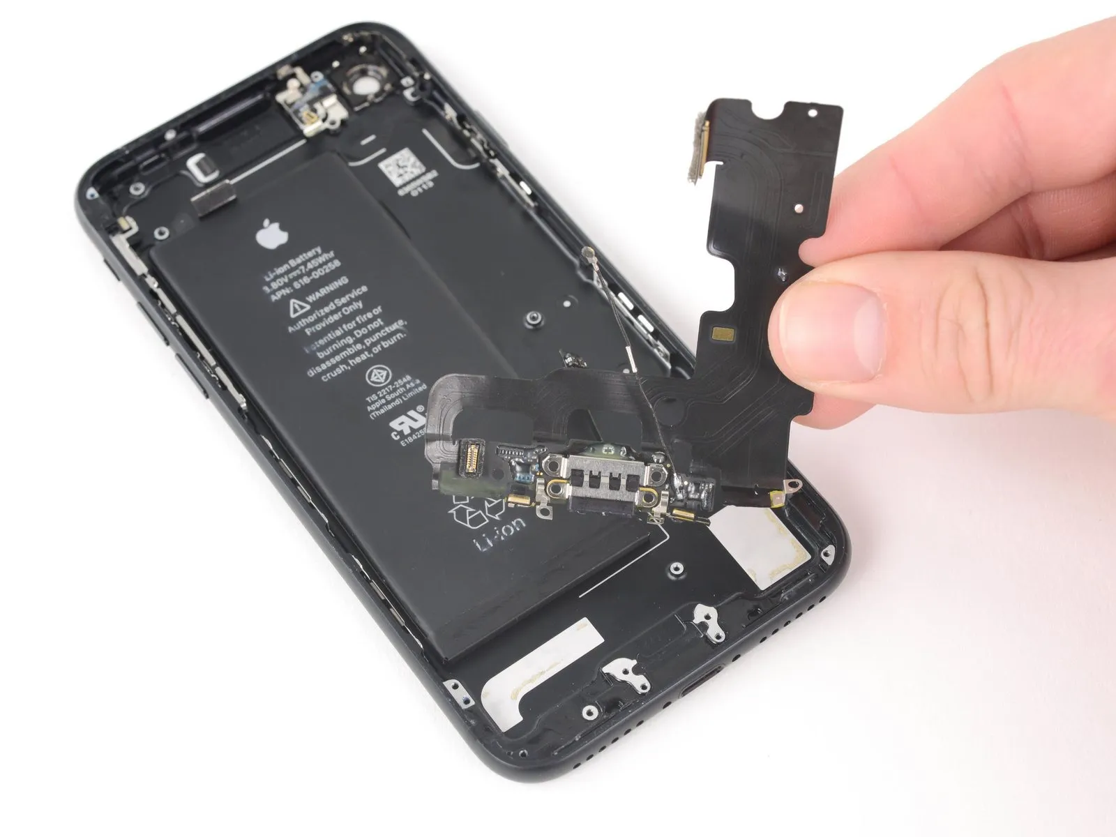


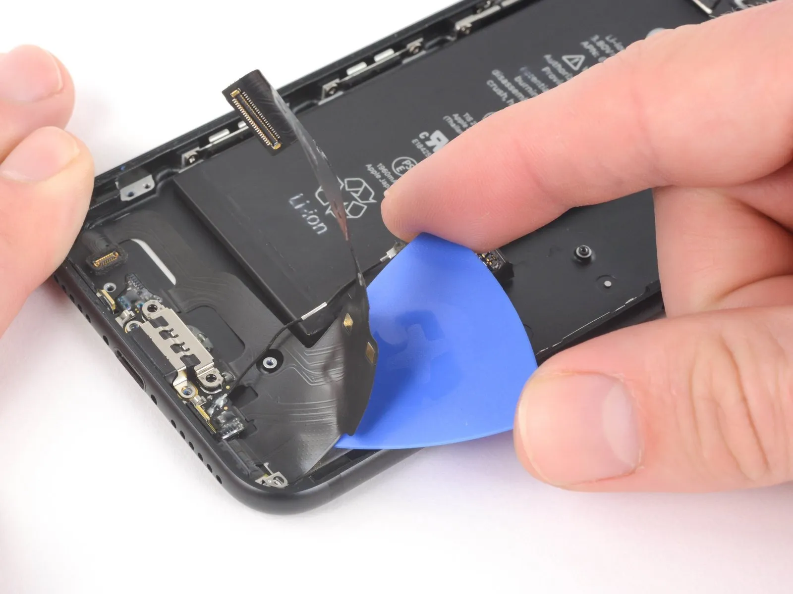
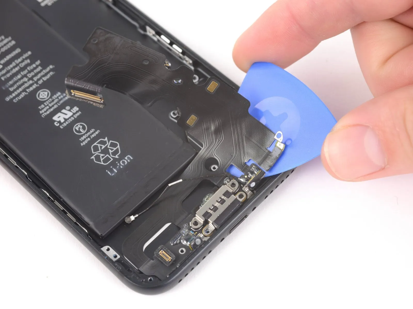
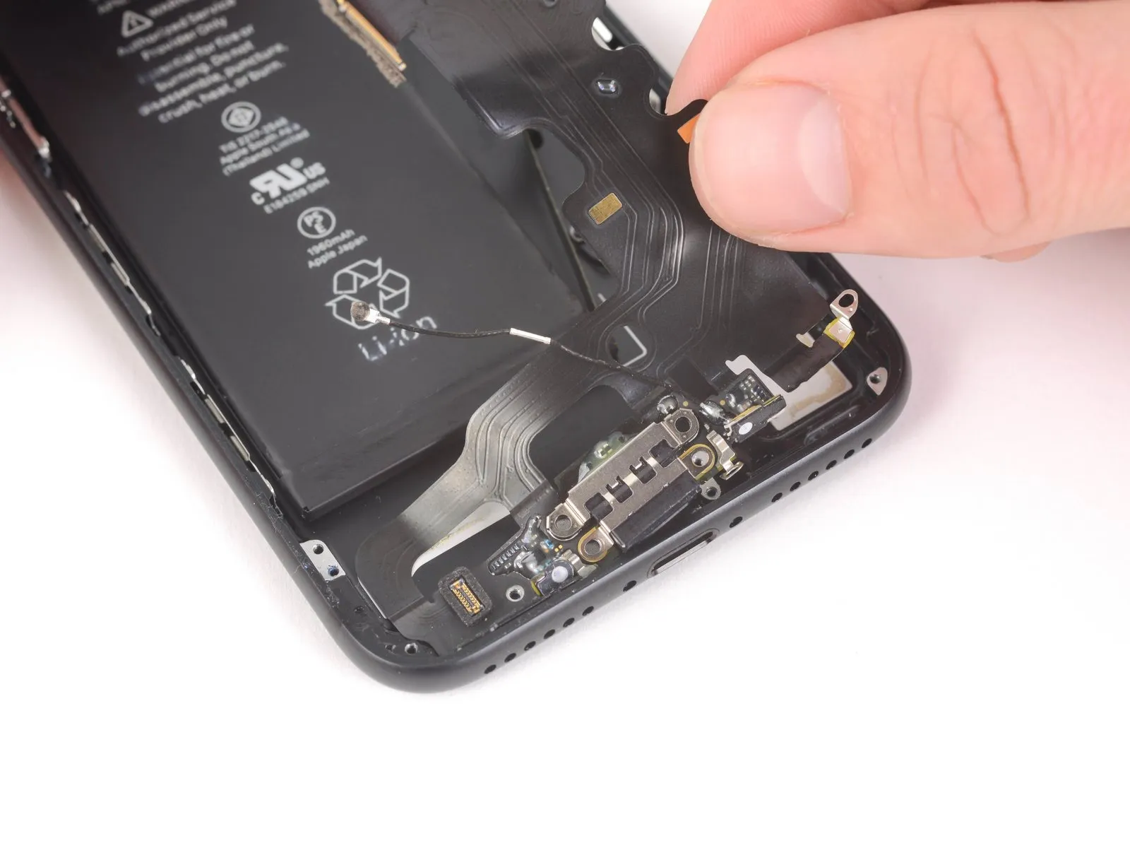
- Detach the lightning connector assembly.
- To ensure proper function and avoid damage, take the following precautions prior to any work on the Lightning connector assembly.
- Carefully remove any remaining adhesive using a plastic scraper.
- Verify proper alignment of the Lightning connector assembly by observing that the two white markings on the iPhone's rear cover are visible through the two circular openings in the Lightning flex cable; misalignment will prevent successful reconnection to the logic board socket.
Step 68


To safeguard your iPhone against liquid and dust, a rubber gasket is situated on the underside of the Lightning connector. During replacement of the Lightning connector assembly, it might be necessary to gently detach this gasket and reposition it onto the substitute component.
To maintain your iPhone's water and dust resistance, the adhesive backing on the underside of each microphone provides a seal; it's recommended that you substitute both of these adhesive patches prior to Lightning connector assembly installation.