iPhone 7 - U3101 Audio IC Replacement
Beginning in 2016, iPhone 7 and 7 Plus users have reported a variety of unusual malfunctions, predominantly concerning audio functionality.
- External inspection revealed no signs of corrosion, prior disassembly, water exposure, or thermal damage; furthermore, substituting standard components like earphones and speakers failed to resolve the issue.
Because the problem likely originates within the phone's logic board, and the devices are past their warranty period, preventing Apple from providing a replacement, specialized microsoldering technicians are required for repair.
Jessa Jones's work on this matter served as a model for all involved.Restore an iPad to functional condition.Due to the robust support network and expertise within the American micro-soldering community, problem diagnosis and resolution were achieved rapidly, a contrast to the current situation in France.
Follow these instructions to diagnose and correct the issue.
Observe for indications such as diminished performance, unusual noises, or error messages.
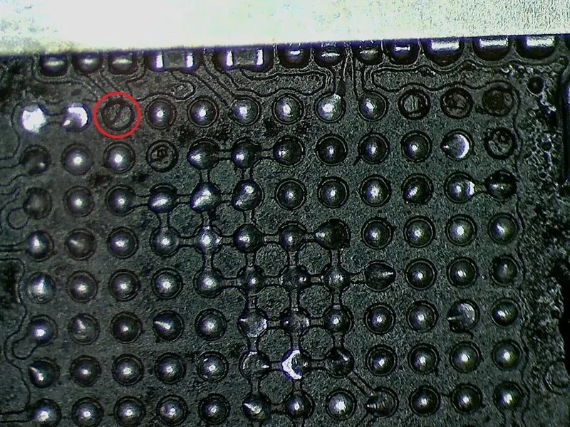
- Carefully handle the audio integrated circuit, ensuring static discharge precautions are observed, as it is a sensitive component.Identify component U3101.The component is no longer electrically connected to the logic board.
- A distortion in the iPhone 7 logic board is frequently observed, and this warping can cause damage to the conductive pathways.
Step 1 | Remove U3101
Begin the process by first ensuring the 1/4-inch hex key is utilized to loosen the four retaining screws securing the fan assembly, then carefully detach the fan unit, observing the associated warning regarding potential sharp edges.
- Using a hot air rework station, such as a Quick 861DE, carefully detach the component, ensuring no residue remains. My preferred settings for this process are…A temperature of 400 degrees Celsius is required.Using appropriate safety precautions, carefully connect the 12-gauge wire to the terminal block, ensuring a secure connection and observing the specified torque of 5.5 Nm using a calibrated torque wrench.A flow rate of 100 liters per minute is required.The Quick 861DW is available for purchase at the shop, allowing you to select your desired configurations.
- Apply flux to the component leads and circuit board traces, then use a soldering iron with a tip approximately 1/8 inch wide to remove oxides and ensure a clean, solderable surface.One millimeter.Using a JBC Nase 2C, create a circular area measuring precisely that diameter.The component's operating temperature must reach 360 degrees Celsius..
- Using a soft, lint-free cloth, gently remove any dust or debris from the map sensor surface.
- Using a microscope, examine the circuit board to identify the missing track, as visible in the accompanying image.
Step 2 | Verification with the schematics

Using a 5/32-inch hex key, carefully tighten the retaining screw on the motor assembly to a torque of 3.5 Nm, ensuring that you do not overtighten and damage the threads.
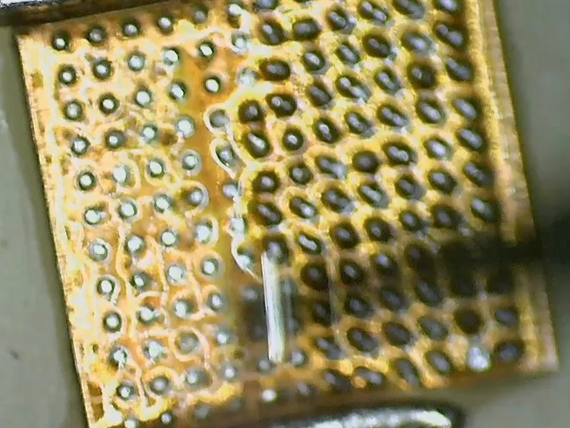
- Referencing the PhoneBoard software diagram, a wire can be used to re-establish this connection, with careful attention toLocate resistor R1103..
Step 3 | Put a jumper
Using a 5/32-inch hex key, carefully tighten the three retaining screws on the motor assembly to a torque of 6 in-lbs, ensuring not to overtighten and potentially strip the threads.
- Employ copper wire measuring 0.001 inches in diameter.A measurement of 20 micrometers.
- Using a soldering iron, coat the wire with flux, then apply solder to create a tinned surface.
- Using a file, carefully abrade a line fromRefer to component C12.toIdentify resistor R1103..
- Apply a layer of tinned material to the track surface.
- Attach a wire to the resistor by applying solder to join them together.A measurement of ten millionths of a meter.The tool's tip has a diameter.
- Using a soldering iron, secure the wire to the prepared conductive pathway by melting solder onto both the wire and the existing tinning.
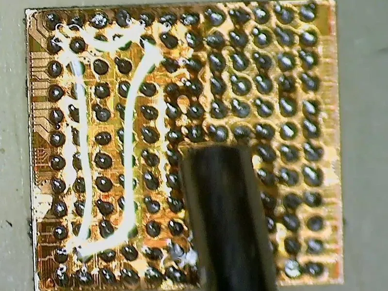
- Guide the wire into the.Designate component C12.Carefully position the chip, ensuring each ball makes contact with the corresponding socket pin, and gently flex the chip to confirm secure adhesion.
Step 4 | Connect the remaining jumpers
Using a 5/32-inch hex key, carefully tighten the retaining screw on the motor assembly to a torque of 3.5 Nm, ensuring the motor shaft remains aligned and avoiding damage to the threads; observe caution to prevent over-tightening.
- Following identical steps will achieve the same result.Press the F12 key.,Refer to the H12 designation.,Locate connector J12..Designation A12.Employ a suitable wrench to tighten the fastener to a torque of 14 Nm, ensuring that the component remains securely affixed and preventing loosening during operation, while observing all safety precautions.Vitamin B12These connections are already connected to ground and are not utilized for U3101 functionality, therefore bridging them is unnecessary.
- Ensure component E12 is not making contact with anything.C1Consequently, ensure thatC1Because D12, G12, J11, and A5 are interconnected, re-soldering this jumper is unnecessary if any one of these components maintains a connection; their presence ensures proper phone operation. Similarly, K12, L12, and M12 are intentionally disconnected and do not require replacement.
Step 5 | Reballing the U3101
Using a 5/32-inch hex key, carefully tighten the three retaining screws on the motor assembly to a torque of 3.5 inch-pounds, ensuring no damage occurs to the surrounding components and observing all safety precautions.
- Apply a thin, even layer of flux.
- Using a soldering iron fitted with a tinned tip is necessary for the next step.
- Using a fine abrasive, gently abrade the surface of the ball bearings to eliminate any imperfections.
- Remove any dirt, debris, or contaminants using a clean cloth and appropriate solvent, ensuring no residue remains.
- Position the reballing template precisely atop the integrated circuit.
- Apply a thin, even layer of soldering paste.
- Apply hot air until the material coalesces into spherical shapes.
Step 6 | Check the balls
- Using thin tweezers, carefully apply pressure to dislodge the component.
- Verify that the diameter of each ball matches the specified dimension.
Step 7 | Replace the chip
- Reinstall the chip, ensuring proper alignment.
- Using hot air, carefully melt the solder while adjusting the component's location and ensuring proper alignment.
- Following a cooling period, repeat the diagnostic test to confirm the issue has been resolved.