iPhone 8 LCD and Digitizer Replacement
To simplify the repair process, utilize our repair kit and adhere to this condensed procedure for a complete iPhone screen replacement.
- Designed for experienced repair professionals,this detailed instruction set facilitates the replacement of solely the iPhone 8 LCD and digitizer assembly—commonly referred to as the bare "front panel." This procedure necessitates the careful relocation of multiple components from the original screen to the replacement unit, including the front-facing camera, earpiece speaker, LCD shield plate, and the home button assembly.
During any display or screen repair, meticulous transfer of the originalhome/Touch ID sensoris crucial for proper operation; Apple pairs this solid-state button to its corresponding logic board, and replacement will result in its permanent deactivation.
Be aware that if your iPhone's automatic brightness setting exhibits malfunctions following the screen repair, ensure your device is running iOS 12 or a later version. True Tone functionality is inherently deactivated after a screen replacement, even when employing anauthentic Apple screen.
Step 1 | Remove the pentalobe screws
- As a preliminary precaution, ensure your iPhone's battery has been depleted to a level below 25% prior to commencing the repair process.A fully charged lithium-ion batteryposes a significant fire hazard and potential for explosion if it sustains accidental physical damage, such as a puncture.
- To prevent any electrical hazards or short circuits, completely deactivate your iPhone before starting the disassembly procedure.
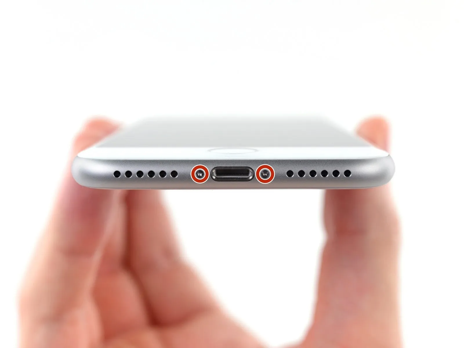
- Using a 3.5 mm pentalobe screwdriver, carefully extract the pair of screws located on the lower edge of the iPhone.
- Separating the iPhone's display assembly will irreversibly damage its integrated waterproof barriers; therefore, acquire replacement seals beforehand to maintain water resistance, or exercise extreme caution to prevent moisture ingress if you intend to reassemble the device without new seals.
Step 2 | Mark your opening picks


- To avoid potential harm to your device, ensure the opening pick isn't inserted beyond its intended depth; this procedure details how to mark the pick to safeguard against such damage.
- Determine the length of3 mmfrom the pick's leading edge, then use a permanent marker to indicate this measurement on the opening pick.
- For added precision, consider marking the other corners of the pick with varying measurements as well.
- As an alternative method, affix a coin to the pick's shaft,3 mmaway from its tip.
Step 3 | Tape over the display


- To mitigate the risk of additional shattering and potential injury while performing the repair, secure any fractured display glass with tape.
- Apply multiple, overlapping layers of transparent packing tape across the iPhone's screen surface, ensuring complete coverage of the front face.
- This method serves to confine loose glass fragments and maintain the display's stability during the prying and lifting procedures.
- Always utilize safety glasses to shield your eyes from any glass particles that may become dislodged throughout the repair process.
- Should the broken glass impede the adhesion of a suction cup in subsequent steps, consider utilizing a robust tape, like duct tape, folded into a handle to elevate the display.
Step 4 | Anti-Clamp instructions


- The following three procedures illustrate the function of the Anti-Clamp, a specialized tool developed to simplify the initial opening process; should you choose not to utilize this tool, proceed past these three steps to an alternative approach.
- Detailed instructions regarding the Anti-Clamp's operation are available in a separate, dedicated guide.
- Grasp theblue handleand move it in a rearward direction to disengage the Anti-Clamp's securing arms.
- Carefully position the arms across either the left or right side of your iPhone's frame.
- Place the suction cups close to the lower edge of the iPhone, situated directly above the home button—one on the front surface and one on the rear surface.
- Apply pressure by compressing the cups together to establish a secure suction hold on the intended area.
- Should the iPhone's surface prove excessively smooth, preventing the Anti-Clamp from maintaining a firm grip, applying adhesive tape can provide a more textured interface.
Step 5


- To engage the locking mechanism, draw the blue handlein a forward direction.
- Rotate the handlethrough a full 360-degree rotation, continuing until you observe the cups beginning to expand.
- Confirm that the suction cupsmaintain their parallel positioning relative to one another; should they exhibit signs of displacement, a minor adjustment of the suction cups is necessary to restore proper arm alignment.
Step 6


- Employ heat using an iOpenerto guide it between the Anti-Clamp’s arms; alternative heat sources like hair dryers, heat guns, or hot plates are acceptable, but exercise caution as excessive temperatures may compromise the display or internal battery.
- Position the iOpenerto rest along the lower edge of the iPhone’s casing.
- Allow a sixty-second interval to permit the adhesive to soften and create a separation.
- Introduce an opening pickinto the newly formed space.
- Should the Anti-Clamp fail to generate an adequate separation, increase heat application to the area and rotate the handle by ninety degrees.
- Avoid exceeding a ninety-degree rotation at any point, and pause for sixty seconds between adjustments; rely on the Anti-Clamp’s pressure and time to achieve separation.
- Proceed past the following three procedures.
Step 7 | Heat the display
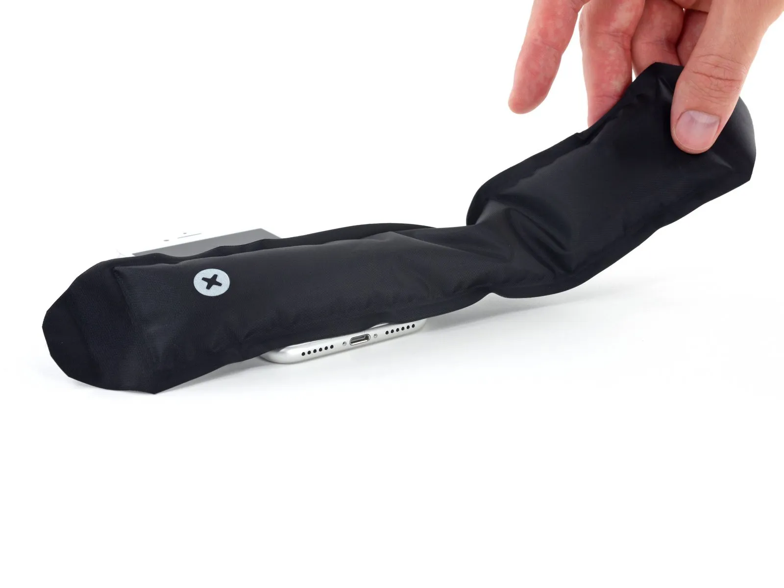
The following sequence of actions details the process of detaching the display assembly with the aid of a specialized tool.a suction cup.
Applying heat to the phone's bottom edge facilitates the loosening of the adhesive bonds holding the display in place, thereby simplifying the separation process.
A hairdryer can be utilized, or alternatively, an iOpener can be employed, applying heat to the lower edge of the device for approximately 90 seconds to reduce the adhesive's tackiness.
Step 8 | Separate the display
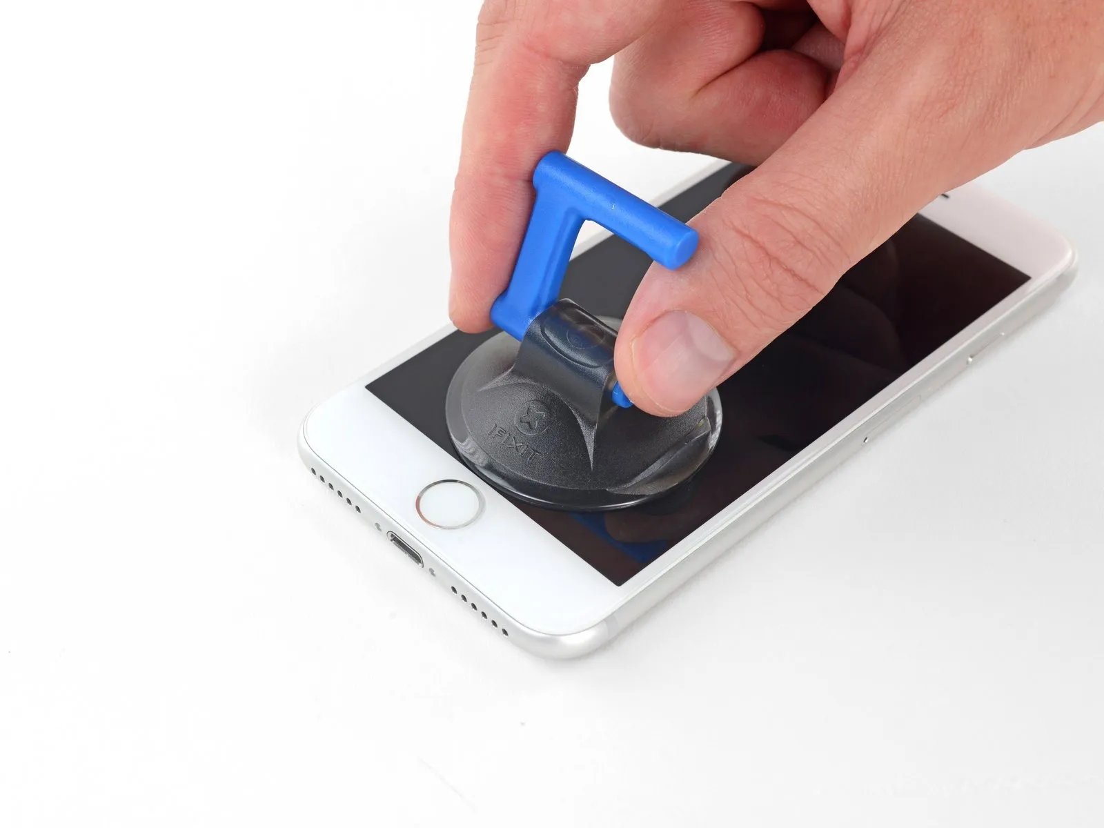

- Position a vacuum attachmentonto the bottom portion of the front panel, situated directly over the home button area.
- Ensure the vacuum attachment's surface remains clear of the home button's location to guarantee a complete bond between the attachment and the glass surface.
Step 9
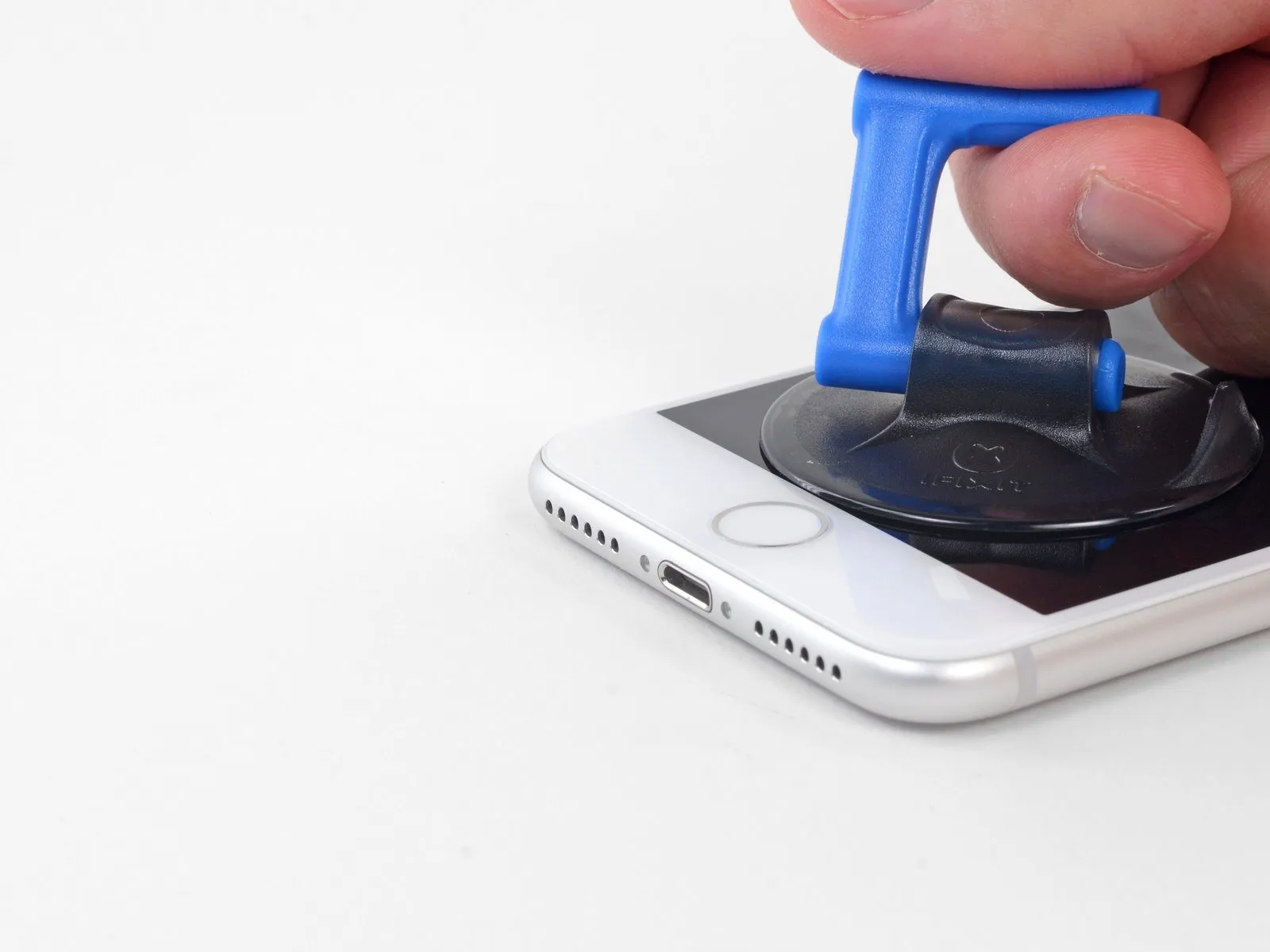


- Apply steady, forceful upward pressure to the suction cup to generate a minimal separation between the display assembly and the device's surrounding structure.
- Introduce an opening tool into the newly formed separation.
- The screen is secured by a robust, waterproof adhesive; establishing this initial separation necessitates considerable force. Should you encounter difficulty in creating this gap, apply additional heat and gently oscillate the display assembly to reduce the adhesive's strength, enabling sufficient separation for tool insertion.
Step 10
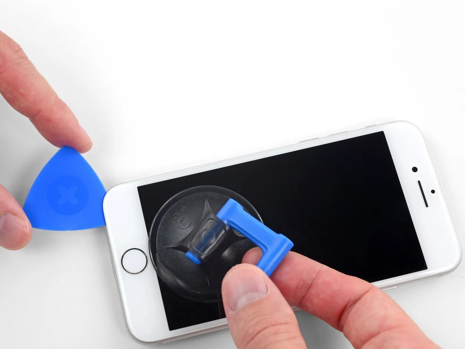


- Begin separating the phone's display assembly by inserting a prying tool beneath the lower edge of the left side, carefully advancing it upwards towards the volume controls and the silent switch, thereby disrupting the adhesive seal securing the display.
- Cease the separation process in the vicinity of the display's upper-left corner.
- Refrain from attempting to disengage the display's upper edge from the rear casing, because it is secured by fragile plastic retaining clips that are susceptible to damage.
Step 11 | Screen information

Fragile wiring is situated along the right-hand side of your iPhone; avoid inserting any tools in this area to prevent potential cable damage.
Step 12
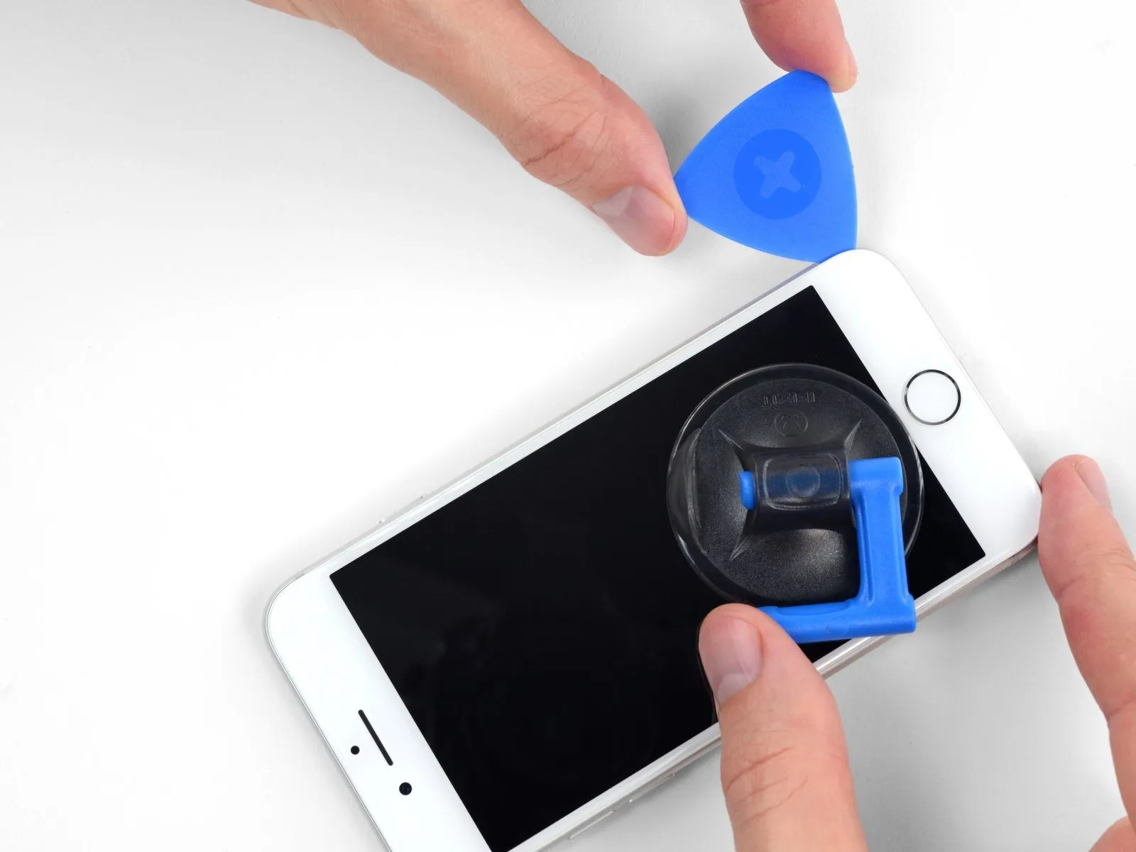


- To release the adhesive, carefully reposition your tool at the lower-right edge of the iPhone, then maneuver it along the corner and up the right side, sliding it to detach the adhesive.
- Ensure your opening tool does not penetrate beyond 3 mm, to prevent potential harm to the delicate display cable connections.
Step 13


- Carefully elevate the display's lower border by exerting upward force on the suction cup.
- Avoid lifting the display beyond an angle of 15 degreesas doing so could potentially damage or sever the flexible ribbon cables that provide the display's electrical connections.
- Detach the suction cup from the front panel by grasping and pulling on the small protrusion located on its surface.
Step 14
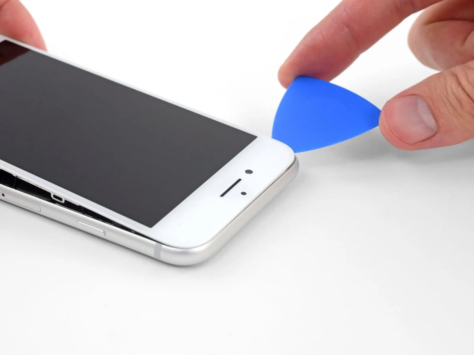

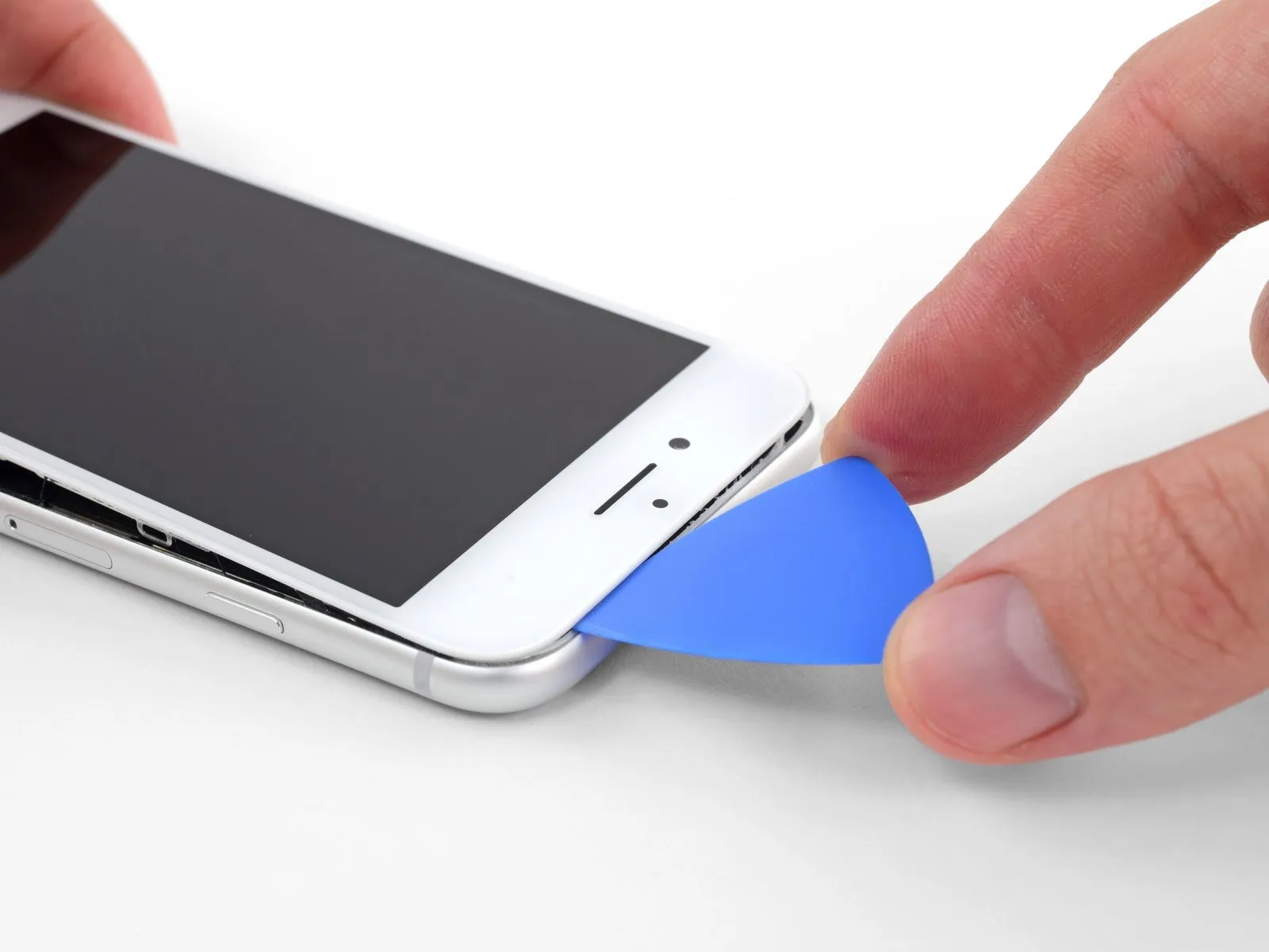
Step 15


Step 16


- Initiate the iPhone's disassembly process by pivoting the screen upwards from the left edge, mimicking the action of opening a book's cover.
- Refrain from completely disconnecting the display assembly at this stage, because multiple delicate ribbon cables remain attached to the iPhone's main circuit board.
- Secure the display in an upright position using a support to prevent it from obstructing your workspace during the repair.
Step 17 | Disconnect the battery


- To detach the lower display cable bracket from the logic board, first, eliminate four Phillips screws that hold it in place; these screws have varying lengths.
- Specifically, two of the screws measure 1.3 millimeters in length.
- The remaining two screws are 2.8 millimeters long.
During this repair process, meticulously organize and document the location of each screw, ensuring correct placement during reassembly; improper screw installation can result in irreversible component failure.
Following screw removal, proceed to take the bracket off.
Step 18


- Employing the tip of a spudger, carefully disengage the battery connector from its corresponding receptacle on the logic board.
To avoid unintended power delivery to the device during the repair process, gently deflect the battery connector cable slightly away from the logic board's socket.
Step 19 | Disconnect the display and digitizer


- Carefully disengage the lower display connector from its socket utilizing the tip of a spudger.
To secure the connector again, apply downward pressure to one edge until a distinct click is heard, then repeat the process on the opposing edge; avoid applying pressure to the central portion. Even minor misalignment during reattachment can result in bending, potentially leading to irreversible damage.
Step 20


- Carefully detach the second lower display cable's connector by utilizing the tip of a spudger.
Step 21


- To detach the bracket that covers the front panel sensor assembly connector, first eliminate the three1.3 mm Phillips screwswhich hold it in place.
- Following screw removal, the bracket can then be taken away.
Step 22


Step 23 | Remove the display assembly
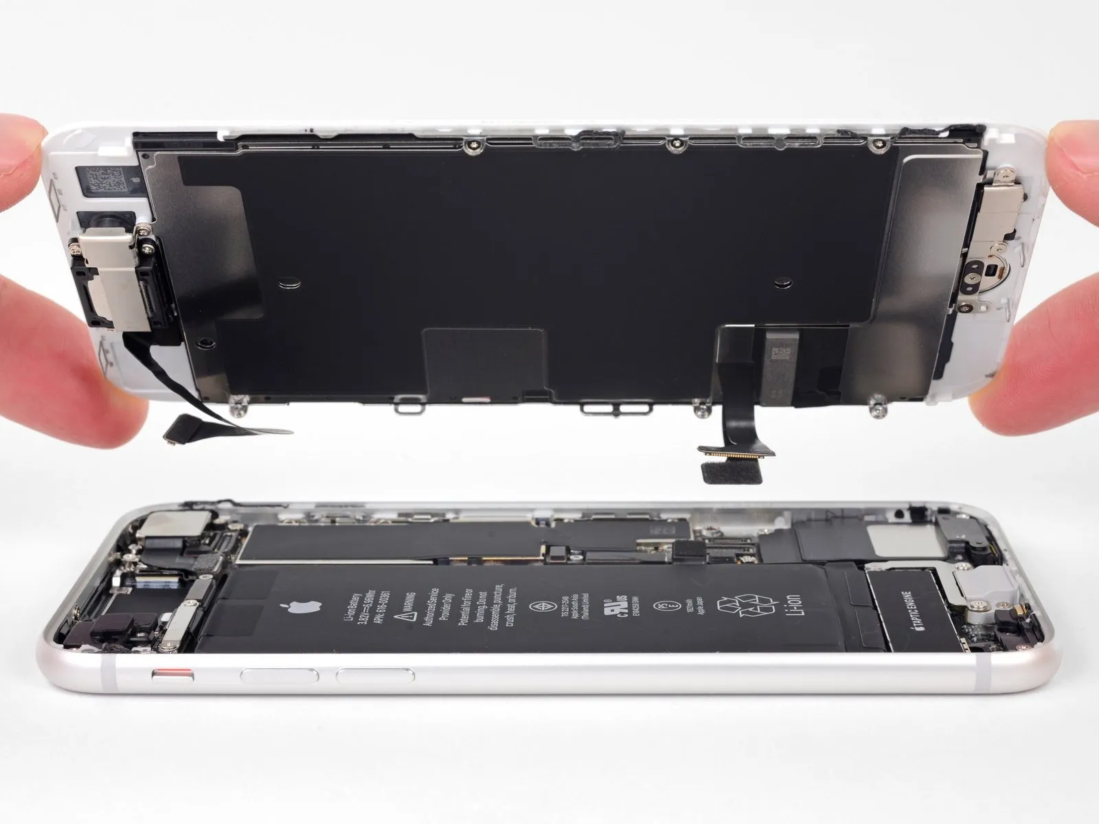
- Detach the display unit from the device.
- When putting the device back together, halt at this stage should you decide to substitute the adhesive securing the display's perimeter.
Step 24 | Remove the home/Touch ID sensor bracket


- Detach the four fasteners to release the bracket that covers the home/Touch ID sensor assembly.Utilize a Y000 screwdriver to loosen these fasteners.The bracket is held in place by these screws.
- A single 1.2 mm screw
- Begin by removing this particular screw; applying too much force while removing the 1.3mm screws initially could potentially damage the home button bracket.
- Subsequently, three 1.3 mm screws
- Once loosened, carefully lift the bracket away.
- When reattaching the bracket, exercise caution to avoid excessive tightening of the screws, as this could impair the functionality of the home button.
Step 25 | Disconnect the Touch ID sensor


- Employ a specialized opening tool to carefully lever beneath the left side of the home button cable connector, facilitating its detachment from the receptacle.Should the entire connector assembly lift unexpectedly without complete separation, apply downward pressure to the cable's upper region using the flattened end of a spudger, concurrently maintaining upward leverage on the connector's left edge.Exercise extreme caution during this process to prevent any harm to the cable or connector, as damage will result in irreversible sensor malfunction.
- This procedure requires the use of an opening tool.
Step 26 | Remove the Touch ID sensor

- Applying warmth to the region surrounding the home button and Touch ID sensor can loosen the adhesive securing its fragile cable, which will simplify its safe removal.
- Turn the display assembly so the reverse side faces up. Utilize a hairdryer or an iOpener, directing heat to the lower display edge for approximately 90 seconds to reduce the adhesive's tackiness.
- Avoid excessive heat when warming the display; it should feel uncomfortably warm to the touch, but not scalding.
Step 27


Employ a specialized opening tool to carefully disengage the adhesive securing the home/Touch ID sensor cable to the rear surface of the display assembly.Utilize a prying implement to delicately release the bonding agent that retains the home/Touch ID sensor cable to the backside of the display panel.A separation tool should be used to cautiously detach the adhesive which secures the home/Touch ID sensor cable to the rear of the display panel.
Step 28

- Detach the home/Touch ID sensor assembly by carefully prying it upwards from the display's front surface.
- For reassembly, initially guide the cable through the designated opening located on the display's front, referencing the provided visual guide.
- The newly acquired component might include surplus Y000 screws positioned close to the Home Button; discard these excess screws to facilitate proper reinstallation of the home button bracket.
Step 29 | Remove the earpiece bracket

- Detach the three fasteners to release the upper earpiece mounting bracket from the front panel's surface.These fasteners are Phillips head screws.The bracket is affixed using these screws.
Specifically, two screws with a 2.6-millimeter diameter are utilized.
Additionally, a single screw measuring 1.8 millimeters in diameter is also employed.
Step 30

- Detach the securing bracket that holds the earpiece speaker in place.
Step 31 | Move the front-facing camera


- Carefully raise the front camera assembly from its connector and pivot it to a position that allows access to other components.
Step 32 | Remove the earpiece speaker

- Detach the earpiece speaker from the front panel by eliminating the two fastening screws.These screws are of the Phillips head type.The speaker is held in place with these fasteners.
A single 1.8-millimeter screw is utilized for this purpose.
Additionally, a 2.3-millimeter screw is also employed to secure the speaker.
Step 33

Step 34 | Remove the front camera and sensor cable

- Using a heat source, warm up aiOpenerand position it against the top edge of the display screen, facilitating the melting of the adhesive securing the front-facing camera and sensor assembly.
- Allow approximately two minutes to elapse before proceeding to the subsequent step, ensuring the adhesive is sufficiently pliable.
Step 35


- Employ the tip of a spudgerto carefully dislodge the proximity sensor from its housing on the device's front surface.
- Ensure the tool's insertion extends completely beneath the sensor to detach it from the underlying transparent plastic component; otherwise, the sensor could detach from its cable harness, necessitating a replacement. This concern is irrelevant if a sensor/cable assembly replacement is already planned.
Step 36


- Carefully insert the pointed end of a spudgerspudgerto create a gap beneath the ambient light sensor flex cable, then gently raise the sensor assembly from its retaining structure.
Step 37


- Carefully insert a separating tool beneath the front camera cable assembly to release the adhesive securing the camera and its associated sensor cable.
Step 38

- Disconnect the harness linking the front-facing camera and its associated sensor.
Step 39 | Separate the LCD and digitizer


- To proceed, detach the six screws.Utilize a 1.2 mm Y000 screwdriver to remove these fasteners.These screws are located on both lateral aspects of the display assembly.
Step 40

- To facilitate separation, apply heat from an iOpener to the shield's perimeter, specifically the area nearest the home button, which will reduce the adhesive's bonding strength.
Step 41


Employ a specialized opening toola prying implementto carefully separate the adhesive securing the flat display cable to the LCD shield plate, specifically around the home button area.
Step 42


Position a specialized opening toolIntroduce a prying implementCommence separation of the display cable connection from the LCD shield plate by inserting a tool from the lower-right corner and progressing outward.
Step 43


- Carefully raise theLCD shield plateaway from the display assembly's components.
- Exercise caution to prevent damage to the display data cables during theLCD shield plate'sremoval process.
Step 44

The display panel and touch layer are the sole components that persist.