iPhone SE Home Button Replacement
This document provides instructions for substituting the home button assembly within your iPhone SE; the iPhone 5s component is designed to be a suitable replacement.
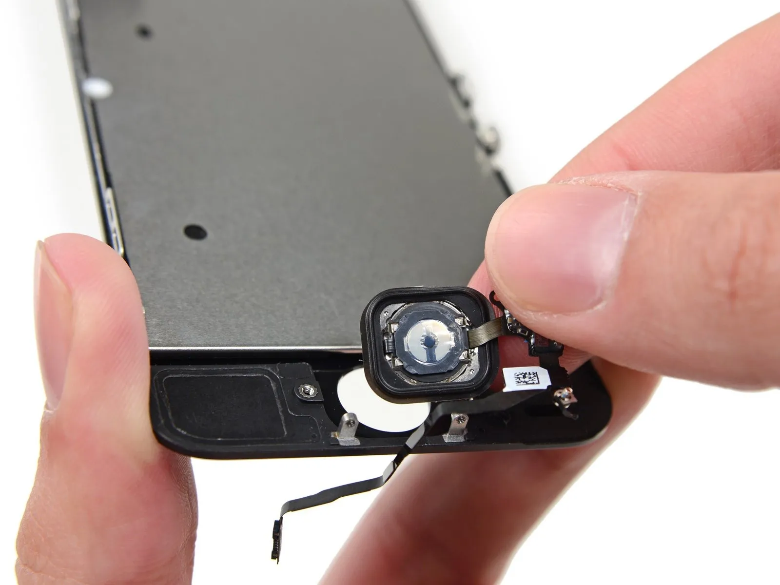
- It is important to recognize that the device's initially equipped home button assembly is the sole component that supports Touch ID functionality.
- A replacement home button will only reinstate standard home button operations, excluding the capabilities associated with Touch ID.
Step 1 | Removing the Pentalobe screws

- To ensure safety, allow your iPhone's battery to deplete to a level below 25% prior to commencing any work.A fully charged lithium-ion batteryposes a fire hazard and potential explosion risk if it sustains accidental damage, such as a puncture.
- Deactivate your iPhone by powering it down completely before starting the disassembly process.
- Using an appropriate tool, extract the pair of 3.9 mm Pentalobe screws located on both sides of the Lightning connector.
Step 2 | Taping the display glass


- To mitigate the risk of additional shattering and potential injury while performing the repair, secure any cracked display glass with adhesive tape.
- Apply multiple layers of transparent packing tape across the iPhone's screen, ensuring complete coverage of the face to retain glass fragments and maintain structural stability during the display separation process.
- Always utilize eye protection, such as safety glasses, to guard against glass particles that may become dislodged throughout the repair procedure.
Step 3 | Display separation prevention


The subsequent instructions detail the process of disengaging the display assembly from the phone's main chassis. The display unit incorporates a glass screen bonded to a plastic bezel, which is secured by metal retaining clips.
It is critical to ensure the complete display assembly is lifted, irrespective of the chosen prying instrument.
Should the glass layer begin to detach from the plastic frame, as illustrated in the initial image, insert a plastic opening tool into the gap between the plastic frame and the metal phone body to release the metal clips from their housings.
For reassembly of a device where the display bezel has previously become detached, applying a narrow adhesive strip between the plastic bezel and the glass can help maintain closure.
Step 4 | Anti-Clamp instructions


- The following two procedures showcase the Anti-Clamp, a specialized tool developed to simplify the initial opening process. Should you choose not to utilize the Anti-Clamp, proceed to the steps located further down for an alternative approach.
- Detailed instructions regarding the operation of the Anti-Clamp are available in a separate, dedicated guide.
- To release the locking mechanism, draw the blue handle in a rearward direction, which will disengage the Anti-Clamp's arms.
- Carefully position the arms across either the left or right side of your iPhone.
- Place the suction cups close to the lower edge of the iPhone, situated directly above the home button—one on the front face and one on the rear.
- Apply pressure by compressing the cups together to establish a secure suction hold on the intended area.
- In situations where the iPhone's surface exhibits excessive slipperiness, preventing the Anti-Clamp from maintaining a firm grip, utilize the provided tape pad to enhance surface traction.
Step 5


- To engage the locking mechanism, draw the blue handle in a forward direction.
- Rotate the handle a full rotation of 360 degrees, or until you observe the cups beginning to expand.
- Confirm that the suction cups maintain their parallel orientation; should they become misaligned, slightly release the suction and readjust the arms.
- Position an opening pick beneath the display screen once the Anti-Clamp has established a noticeable separation.
- Should the Anti-Clamp fail to generate an adequate gap, adjust the handle by a 90-degree rotation.
- Avoid excessive rotation, limiting adjustments to a quarter turn at a time, and allowing brief pauses between rotations to permit the Anti-Clamp to function and the separation to progress.
Step 6 | Manual Opening Procedure

In the absence of an Anti-Clamp tool, a solitary suction cup can be employed to elevate the front panel.suction cupTo raise the front panel, utilize a suction cup.
- Apply a suction cupto the display surface, positioned directly above the home button.
- Ensure the cup establishes full contact with the screen's surface to achieve a secure and airtight bond.
Step 7 | Start lifting the front panel assembly

The front panel's attachment relies onclips, alongside multiple flexible ribbon cables that link it to the phone's internal components. The objective during this step is to disengage the clips and only partially open the device to allow for cable disconnection. Exercise caution and deliberate movements to prevent any potential damage.
- Ensure the suction cup maintains a secure bond with the front panel assembly, positioned close to the home button.
- Maintaining downward pressure on the iPhone with one hand, lift the suction cup to create a slight separation between the home button area of the front panel and the rear case.
- Using a plastic opening tool, carefully apply pressure to the edges of the rear case, moving them away from the front panel assembly, concurrently with the upward traction of the suction cup.
Proceed deliberately, maintaining consistent and substantial force. The front panel assembly exhibits a considerably tighter integration compared to many other devices.
Step 8


Avoid a full separation of the front panel assembly from the rear case, because multiple sensitive ribbon cables provide their interconnection.
- To break the vacuum, grasp and draw the plastic projection.suction cup.
- Detach the suction cup from the display surface.
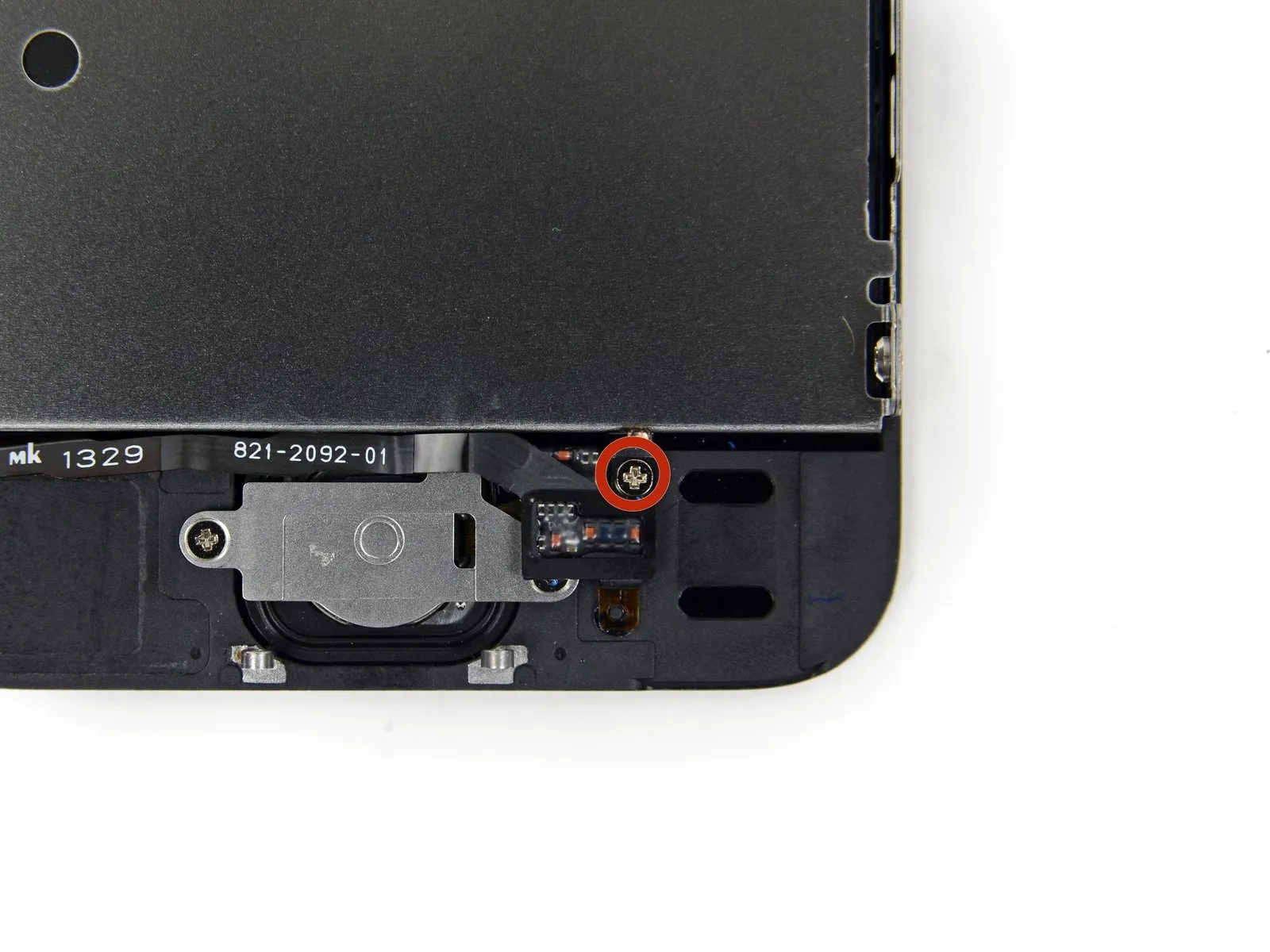
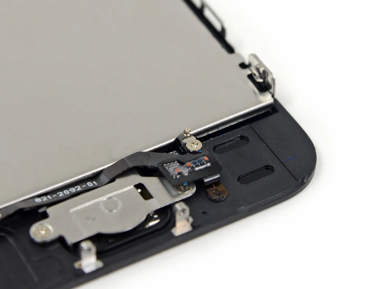
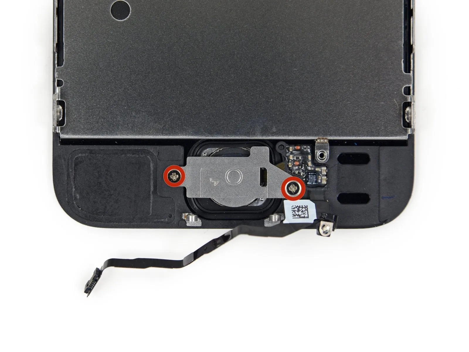
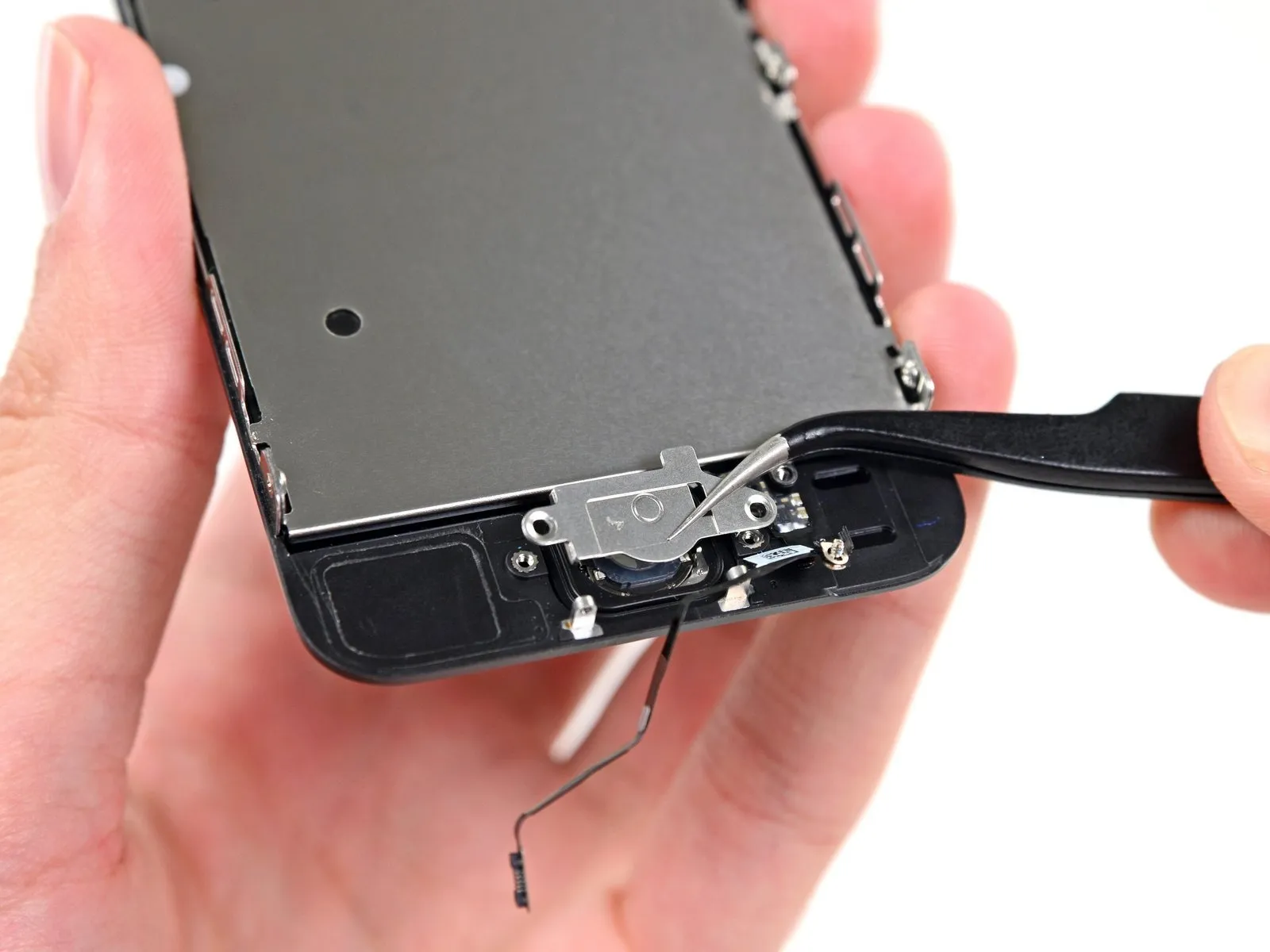
Step 9 | Removing the Touch ID cable bracket


- Carefully separate the phone's casing, exposing the metallic bracket that shields the home button cable.
- Avoid excessive separation of the phone's housing, as this could potentially harm the home button cable or its corresponding connector. Maintain slack in the cable; any noticeable stretching indicates the opening is excessive.
- The phone's original home button assembly is essential for Touch ID functionality; substituting it with a replacement will only restore basic home button operation, excluding Touch ID features.
- Employ the pointed end of aspudgerto disengage the bracket and subsequently remove it with tweezers.
- The following two procedures are specifically for reassembly; disregard them and proceed to Step 12 until the reassembly process begins.
Step 10


When putting the device back together, it's essential to reattach the Touch ID cable bracket. Ensure the upper portion of the bracket is positioned between the battery and the Touch ID cable connector, specifically in front of the metal tab. Subsequently, the lower section should secure itself over the connector.
- To position the bracket, guide the upper portion over the Touch ID cable connector, moving from the left side to the right.
- As an alternative method, place the bracket directly above the connector; the side featuring the "leg" will elevate the bracket at a small incline, while the opposing edge must be situated between the cable connector and the metal tab located near the battery. Utilizing the edge of a spudger flat against the bracket, exert a mild downward force to engage the rear and front clasps.
Step 11


When putting the device back together, utilize the planar edge of a spudgerto secure the upper section of the Touch ID cable bracket onto the cable connector with a clicking sound.
Should the bracket not seat completely level, it might be necessary to detach it and reposition it over the cable connector to achieve a more precise alignment.
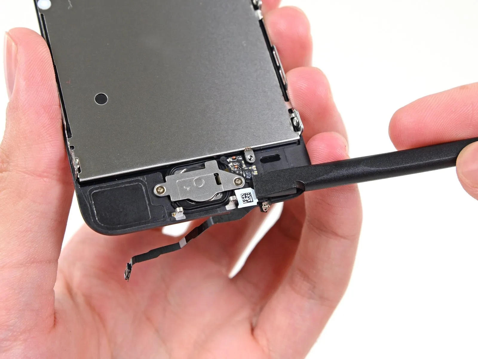
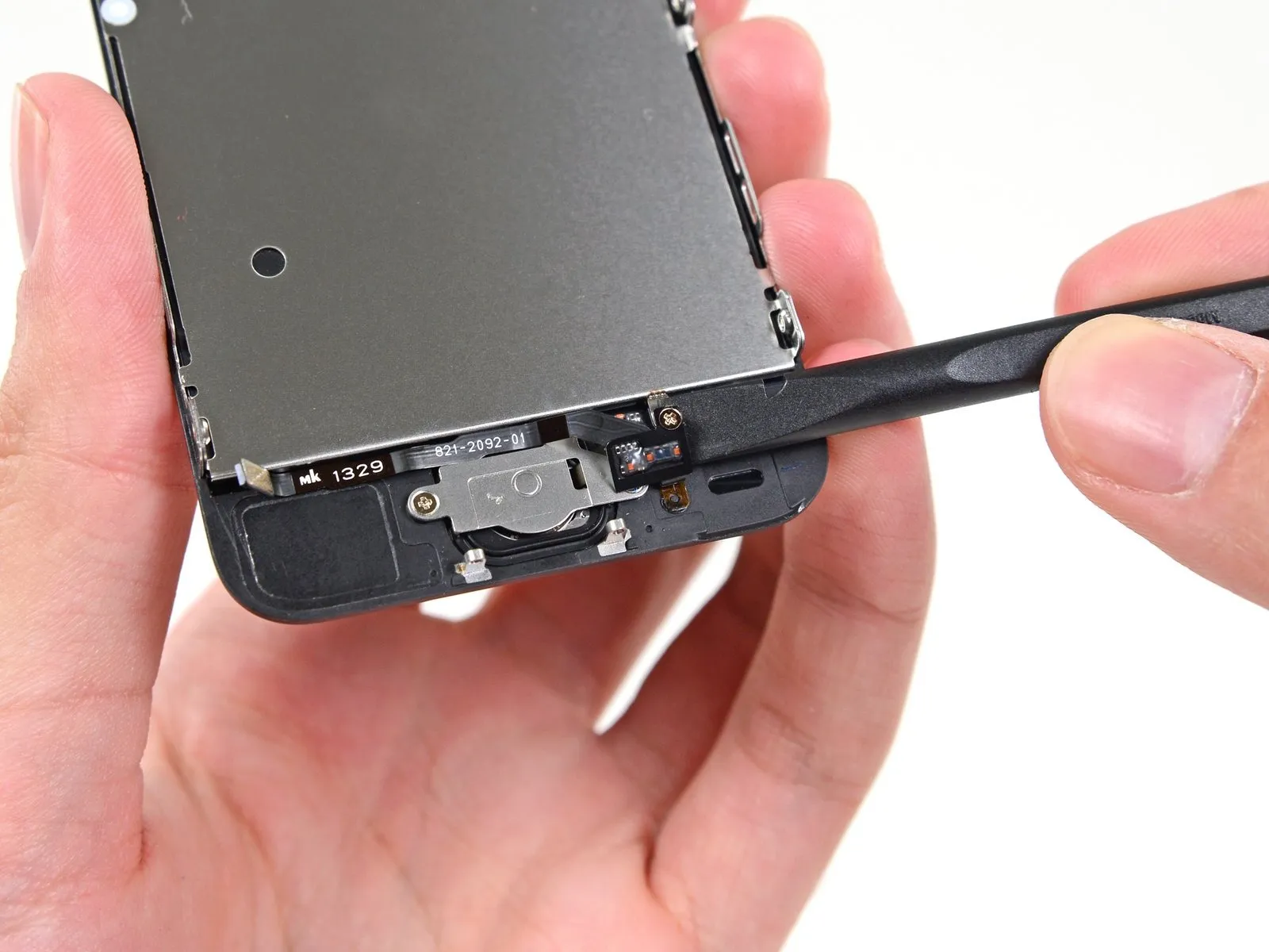
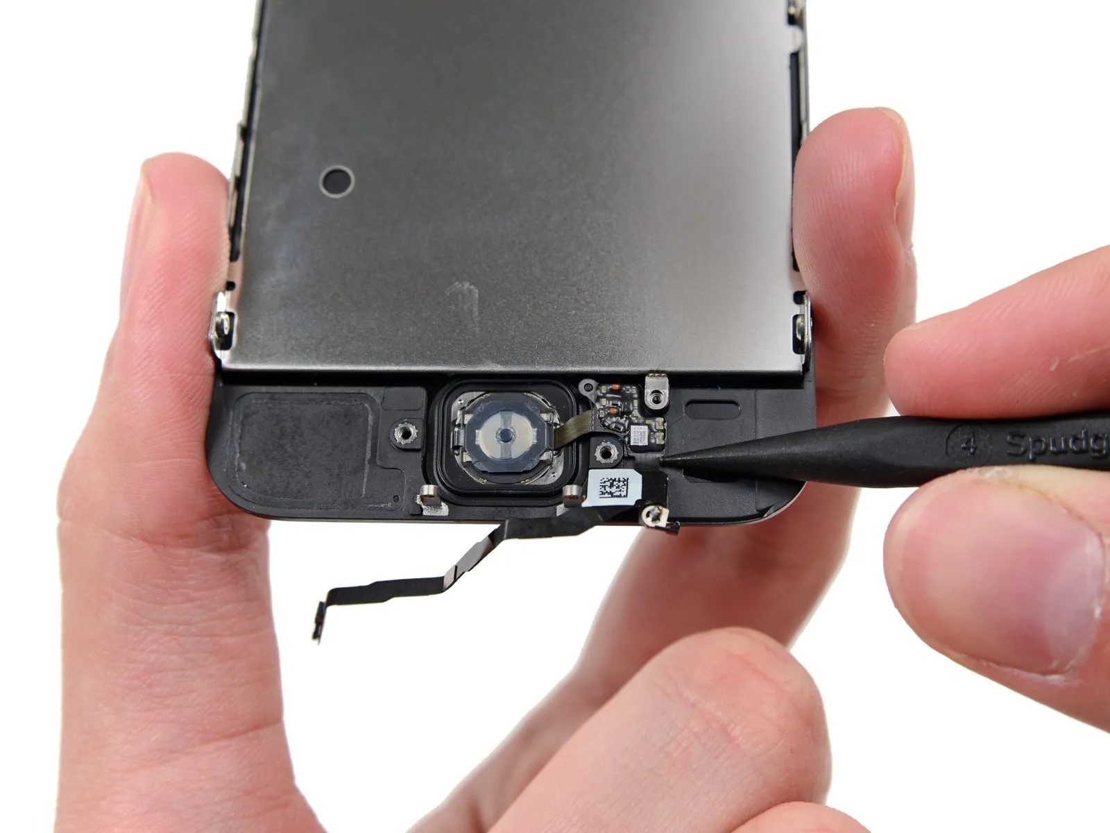
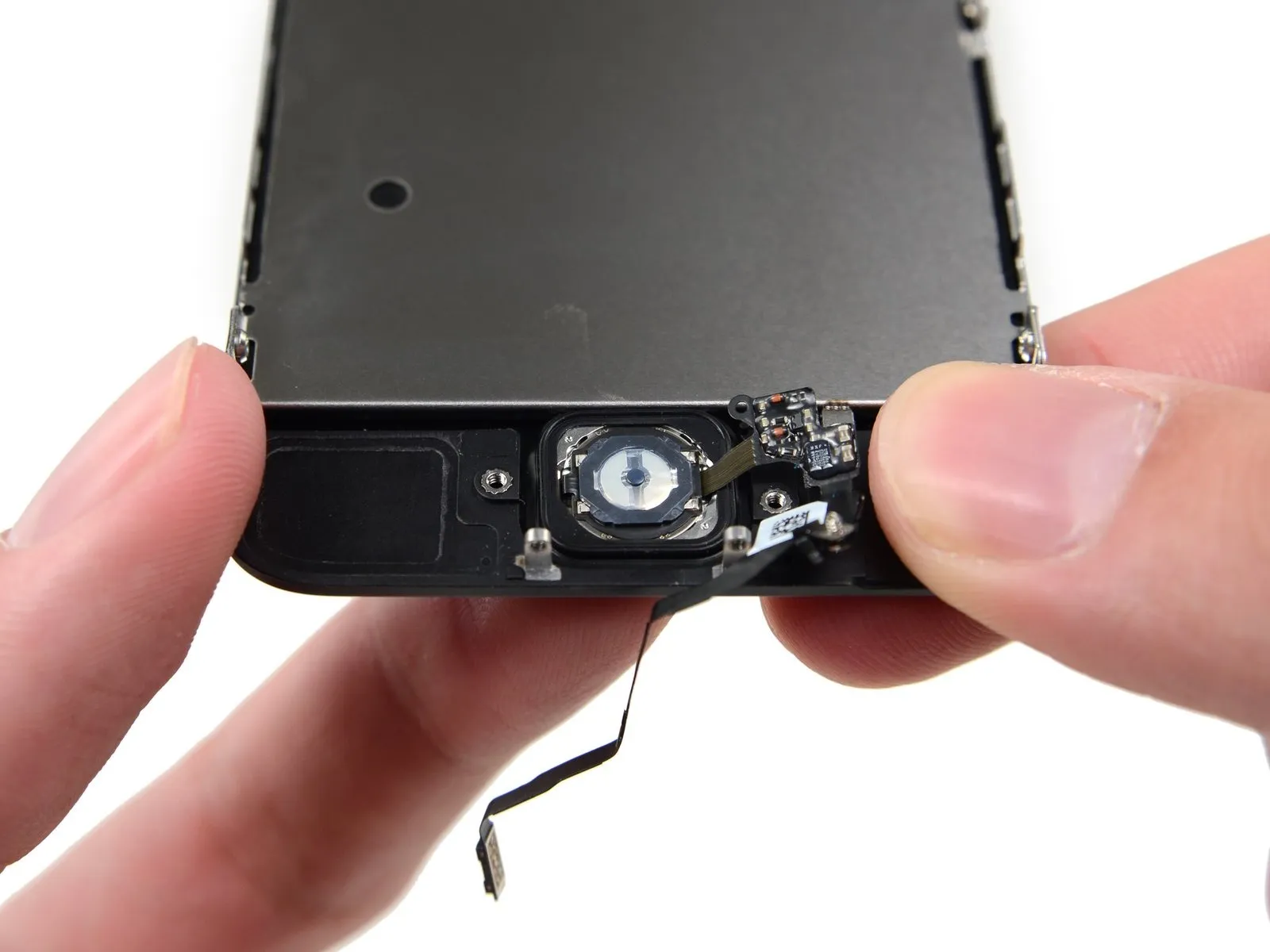
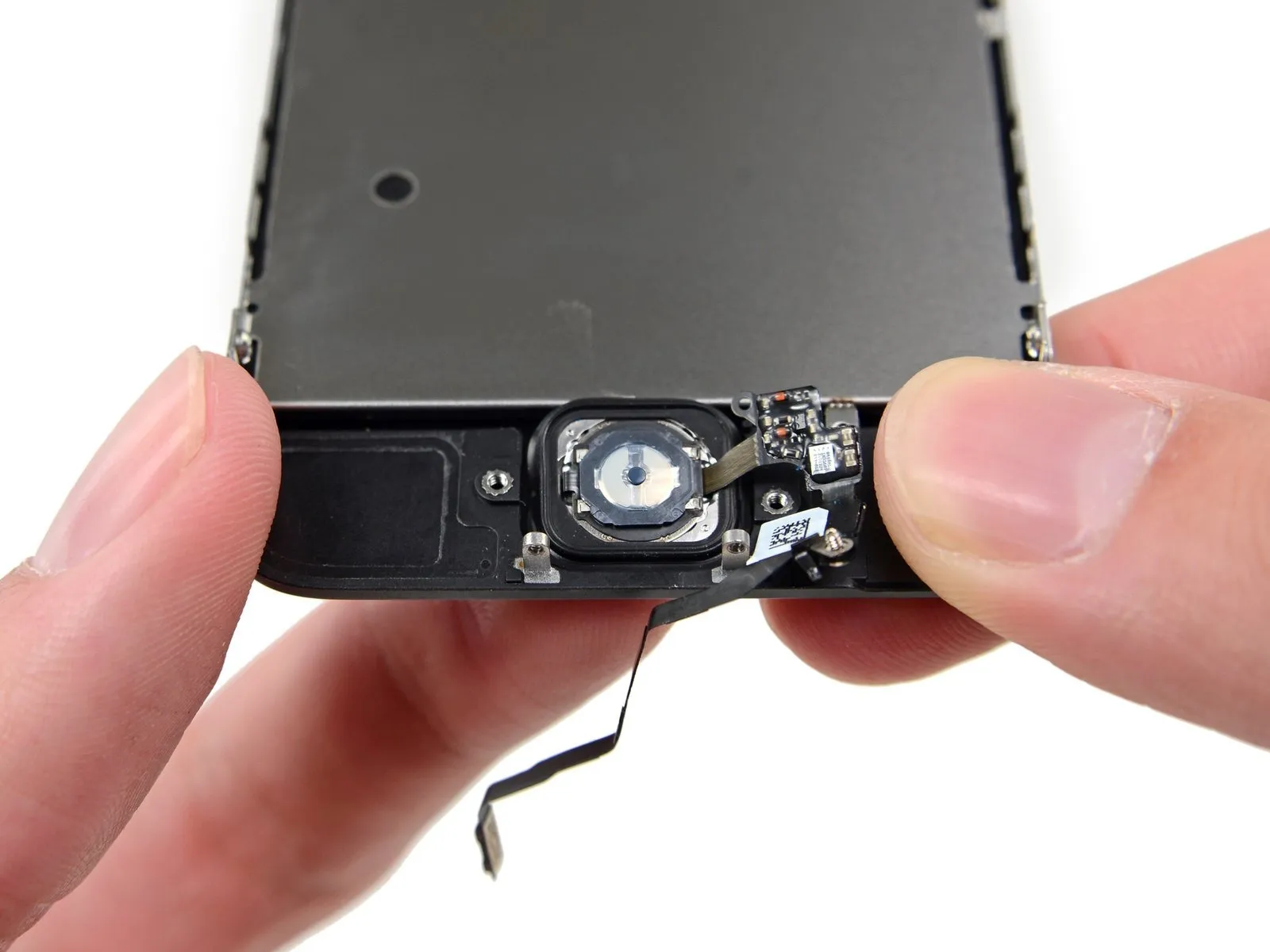
Step 12 | Disconnecting the home button cable connector


- Employ the pointed end of a spudgerto carefully lift the home button cable connector away from its receptacle.
- Confirm that you are disengaging the cable connector from its socket, avoiding the unintended lifting of the entire socket assembly, as the socket is affixed to a separate, glued-down cable that is susceptible to damage if improperly pried.
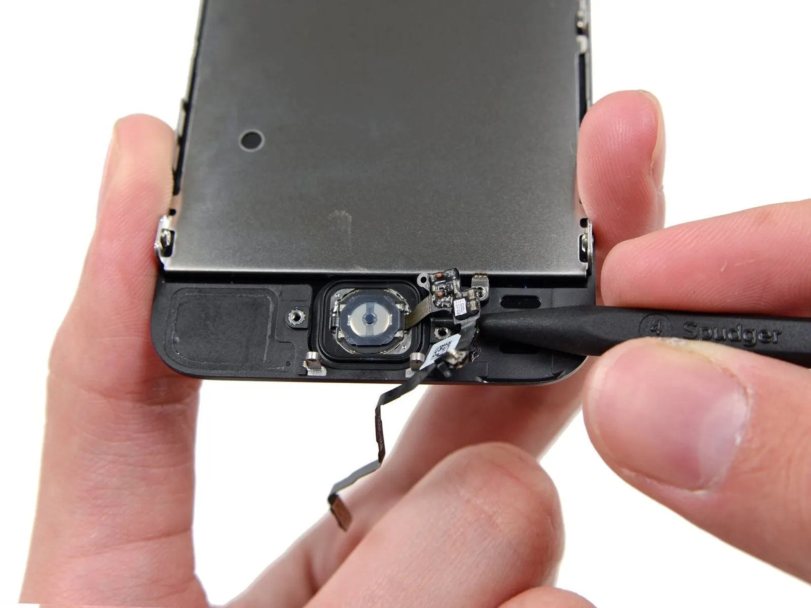
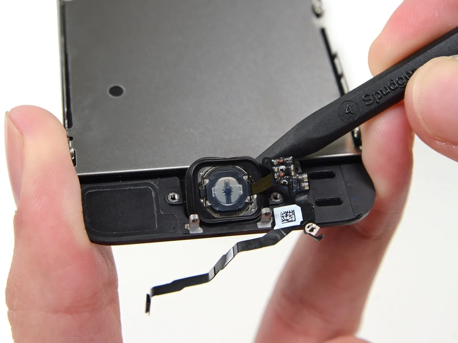
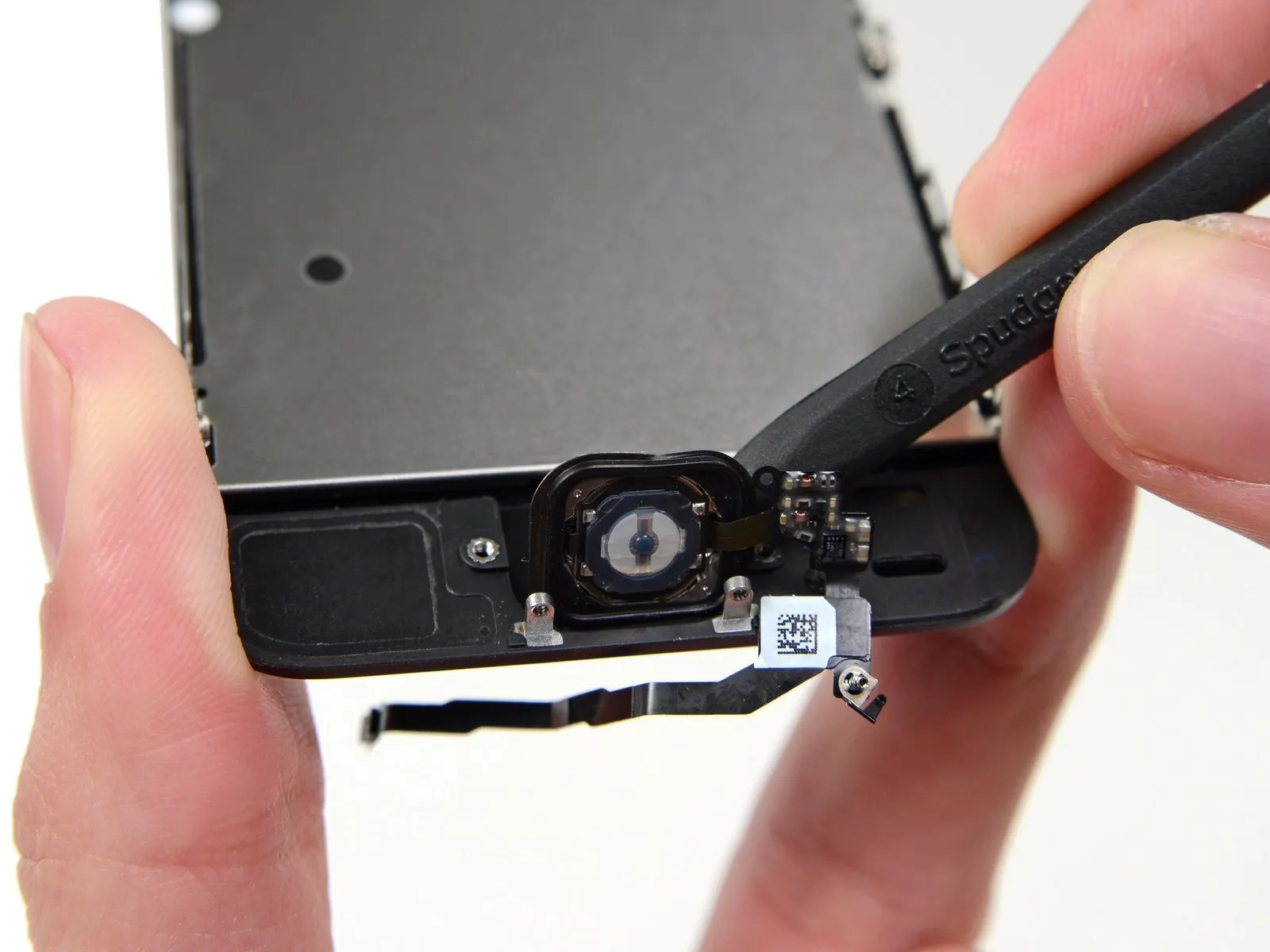
Step 13 | Opening up the phone


- After disengaging the connector, carefully separate the home button end of the assembly from the rear case, utilizing the top edge of the device as a pivot point.
- Position the display open to approximately90-degree angle, and support it with an external object to maintain its position during the repair process.
- Secure the display in place with a rubber band to minimize stress on the delicate display cable connections.
- As an alternative, an unopened beverage container can be employed to temporarily stabilize the display.
Step 14

Step 15

Step 16


- Employ the planar edge of a spudger to carefully disengage the battery connector from its corresponding receptacle on the logic board.
- Exercise extreme caution, ensuring that force is applied solely to the battery connector, avoiding contact with the logic board socket. Applying pressure to the socket or the logic board itself carries the risk of socket destruction or damage to adjacent components.
Step 17

- Detach the front panel cable bracket from the logic board by disengaging the listed screws.
- A 1.7-millimeter Phillips #000 screw is required.
- A 1.2-millimeter Phillips #000 screw is also needed.
- Additionally, a 1.3-millimeter Phillips #000 screw must be removed.
- Another 1.7-millimeter Phillips #000 screw needs to be taken out.
Maintaining precise screw organization during this procedure is vital for successful reassembly. Incorrectly utilizing a1.3-millimeter screw or one of the1.7-millimeter screws within the lower right aperture will cause substantial logic board damage, rendering the device unable to power on.
Avoid excessive tightening and refrain from applying force; if a screw does not align smoothly during reinstallation, verify its size.
Step 18

- Detach the cable securing bracket, which is affixed to the logic board, to facilitate its removal.
Step 19


- Carefully detach the front-facing camera and its associated sensor cable assembly from the device using a non-conductive tool such as a spudger or fingernail.
Step 20


- Prior to detaching or attaching the cable during this procedure, confirm the battery's power is completely removed to prevent potential damage.
Separate the LCD cable's connector from its socket.
During reassembly, the LCD cable could inadvertently become detached from its connection, potentially causing display anomalies such as vertical lines or a completely unresponsive screen upon powering on the device; in such a scenario, re-establishing the cable's connection and performing a power cycle should resolve the issue, and the most reliable method for a power cycle involves briefly disconnecting and reconnecting the battery.
Step 21


Step 22

Step 23 | Home Button Assembly
- Release the solitary, captive screw that holds the home button cable in place.Utilize a Phillips #000 screwdriver for this task.This screw is attached to the home button cable via a spring-loaded contact that provides tension. When reassembling, verify that this contact is positioned correctly, specifically on the side of the screw closest to the LCD screen.
- Should your replacement component lack this captive screw and associated spring contact, it will be necessary to relocate them from the original cable to the new one.
- The captive screw is fastened to the home button cable by a spring contact backing.
Step 24
Step 25
- Detach the two screws, each measuring 1.4 mm and utilizing a Phillips #000 screwdriver, that secure the home button bracket.1.4 mm Phillips #000 screws from the home button bracket.
Step 26
- Carefully detach the retaining bracket securing the home button from the display assembly.
Step 27
- Carefully insert the pointed end of a spudger to gain access beneath the home button cable assembly.
- The home button cableis secured using a light adhesive.
- Apply slight force with the spudger to disengage the home button cable from the front panel assembly.
- Refrain from detaching the home button at this stage, because it remains connected to the front panel assembly.
Step 28
- Should it be required, carefully detach the protective covering that conceals the home button located on the exterior surface of the damaged front panel assembly.
- Exercise caution while applying upward pressure to the upper-leftmost portion of the home button, separating it slightly from the front panel.
- Avoid completely dislodging the home button; a small separation is sufficient to allow for prying with a spudger.
- The membrane component is exceptionally delicate; should you encounter resistance suggesting a potential tear, apply localized heat and attempt the separation once more.
Step 29
Step 30
Step 31 | Home Button


- It might be necessary to relocate the home button gasket onto the new home button assembly.
- Employing tweezers, carefully detach the gasket from the existing home button.
- Because the gasket possesses a minimal thickness, if you detect any signs of tearing during removal, halt the peeling process and apply heat to prevent damage before continuing.
Step 32

- Carefully guide the gasket away from the ribbon cable.
- The potential exists for damage, such as elongation or severance, to the delicate gasket.