iPhone SE SIM Eject Lever Replacement
If the SIM card isn't ejecting properly or appears lodged within the device, follow these steps to either reposition it or install a new one.Inspect the SIM eject lever for damage or malfunction; replacement may be necessary if it fails to properly release the SIM tray.Using the specified tool, perform the action within the designated area.Apple iPhone SE.
Step 1 | Removing the Pentalobe screws

To prevent electrical shock or damage to components, ensure the iPhone is completely de-energized prior to commencing the repair process.
Using a Pentalobe screwdriver, detach the two screws, each measuring 3.9 mm, located on both sides of the Lightning connector.
Step 2 | Taping the display glass


Apply strips of transparent packing tape across the iPhone screen, ensuring complete coverage by layering them until the entire display surface is protected.
To prevent glass fragments from scattering and maintain stability during the display separation process, this technique is essential.
To safeguard your vision, always use safety glasses while working, as fragments of glass may become dislodged.
Step 3 | Display separation prevention


Ensure complete removal of the display assembly, irrespective of the chosen tool.
When the glass and plastic layers detach, mirroring the visual in the initial image, use a plastic opening tool to insert it into the gap between the plastic frame and the phone's metal chassis, carefully levering each metal clip free from the case.
To ensure the phone remains securely closed during reassembly when the display bezel is detached, apply a narrow adhesive strip positioned between the plastic bezel and the glass.
Step 4 | Anti-Clamp instructions


Refer to the included guide for detailed procedures regarding Anti-Clamp operation.
- To release the Anti-Clamp's arms, move the blue handle in a rearward direction.
- Position the arms so they extend across the iPhone's left or right side.
- Affix two suction cups, one to the front and one to the rear of the iPhone, close to the lower edge, situated directly above the home button.
- Apply vacuum to the targeted region by pressing the cups firmly against each other.
- To improve the Anti-Clamp's grip if the iPhone's exterior is excessively smooth, apply the provided adhesive pad to generate a more textured holding area.
Step 5


- Rotate the handle fully, completing a 360-degree turn, observing for the initial expansion of the cups as an indicator of completion.
- Maintain parallel positioning of the suction cups; should misalignment occur, gently release the suction cups' grip and reposition the arms.
- Once sufficient space is created by the Anti-Clamp, slide a prying tool beneath the display.
- To ensure adequate separation, reposition the handle by 90 degrees.
- Apply rotations no greater than 90 degrees, pausing briefly after each adjustment to allow the Anti-Clamp mechanism and a short period of time to facilitate proper seating.
Step 6 | Manual Opening Procedure

- Position a suction cup directly on the display surface, situated slightly higher than the home button's location.
- Ensure the entire cup makes full contact with the screen surface to guarantee a secure seal.
Step 7 | Start lifting the front panel assembly

- Securely affix the suction cup to the front panel assembly, positioning it close to the home button.
- Using one hand to secure the iPhone, lift the suction cup vertically to create a small gap between the front panel's home button area and the rear case.
- Using a plastic opening tool, lift the rear case's perimeter edges away from the front panel assembly, applying upward force with a suction cup to aid separation.
- Exercise caution and use steady, even pressure when installing the front panel assembly, as its fit is considerably more snug than typical device construction.
Step 8


- To detach the suction cup, extend the small plastic projection to break the airtight seal.
- Carefully detach the screen from the device using the suction cup.
Step 9 | Removing the Touch ID cable bracket


- Carefully separate the phone's casing to expose the metallic securing bracket that protects the home button cable.
- To prevent damage to the home button cable and its connector, avoid excessive separation of the phone's components; maintain slack in the cable, as overextension can cause harm.
- The Touch ID feature will only operate with the phone's factory-installed home button assembly; replacement assemblies will function as standard home buttons, lacking Touch ID capabilities. Damage to the cable during replacement will also result in a standard home button function, precluding Touch ID use.
- Employ the pointed end of a screwdriver to apply force.Use a plastic pry tool, often referred to as a spudger, to gently separate components.Using tweezers, carefully disengage the bracket.
- For reassembly procedures, proceed with the following two steps later; if you are currently disassembling, bypass them and move directly to Step 12.
Step 10


To complete reassembly, secure the Touch ID cable bracket by positioning its upper edge between the battery and the Touch ID cable connector, ensuring it clears the metal tab, then fasten the bracket’s lower edge over the connector to engage the latch.
- Align the bracket's upper edge with the Touch ID cable connector and move it horizontally to the right.
- Position the bracket so it covers the connector, noting that the side featuring the projecting "leg" will create a small incline; ensure the opposing edge sits between the cable connector and the battery's adjacent metal tab.Use a plastic pry tool, often referred to as a spudger.Align the component flush with the bracket, then secure it by lightly pressing downwards to engage both the rear and front clasps.
Step 11


Employ the tool's planar edge to facilitate reassembly.Use a plastic pry tool to gently separate.Secure the Touch ID cable connector by pressing the front section of its bracket firmly into place.
To ensure the bracket sits level against the surface, reposition it by sliding it back over the cable connector if it doesn't seat properly.
Step 12 | Disconnecting the home button cable connector


- Employ the pointed end of a screwdriver to apply force.Use a plastic pry tool to gently separate.Use a spudger to carefully lift the home button cable connector vertically from its receptacle.
- Carefully detach the cable connector from its receptacle; avoid lifting the receptacle itself, as it's secured to a separate, adhesive-backed cable that could be damaged if pried.
Step 13 | Opening up the phone


- After disconnecting the connector, pivot the assembly, using the phone's top edge as a fulcrum, to separate the home button end from the rear case.
- Carefully separate the display assembly from the device housing, creating a gap of approximately 1 millimeter.Rotate to a 90-degree angle.Position the device at an angle, securing it in place with support to prevent movement during the repair process.
- To avoid stressing the display's wiring during the repair process, secure it with a rubber band.
- As a temporary substitute, an unused, sealed can of soda can be employed to support the screen.
Step 14

Step 15

Step 16


- Carefully lift the battery connector away from its corresponding socket on the logic board, utilizing the flat edge of a spudger to avoid damage.
- Exercise extreme caution when releasing the battery connector; lifting force should be applied solely to the connector, avoiding any pressure on the logic board socket or the board itself, as this could result in socket damage or harm to adjacent components.
Step 17

- Detach the cable bracket that holds the front panel assembly wires from the logic board by unscrewing the screws listed below.
- A Phillips screwdriver, size #000, is needed to remove a 1.7-millimeter screw.
- A Phillips head screw, size #000 and measuring 1.2 millimeters.
- A Phillips screwdriver, size #000, is needed to remove a 1.3-millimeter screw.
- An additional screw, measuring 1.7 mm in length and utilizing a Phillips #000 head, is required.
Carefully note the location of each screw during this stage to ensure correct reinstallation, as employing the incorrect screw size can damage components.Use a screw with a diameter of 1.3 millimeters.Alternatively, aUse screws with a 1.7-millimeter head diameter.Inserting a tool into that specific lower-right aperture risks substantial logic board damage, preventing the device from powering on.
Avoid applying excessive force when fastening screws; overtightening can damage components. If resistance is encountered during installation, verify that the screws are the correct size.
Step 18

- Detach the bracket securing the front panel assembly cable to the logic board.
Step 19


- Carefully detach the front camera and sensor assembly's cable using a spudger or similar tool.
Step 20


- Prior to either detaching or reattaching the cable in this procedure, ensure the battery is disconnected.
Carefully separate the LCD cable connector.
Should the LCD cable become detached from its connector during reassembly, the display may exhibit white lines or remain blank upon powering on; to resolve this, reattach the cable securely and restart the device by disconnecting and reconnecting the battery.
Step 21


Step 22

Step 23 | SIM Tray
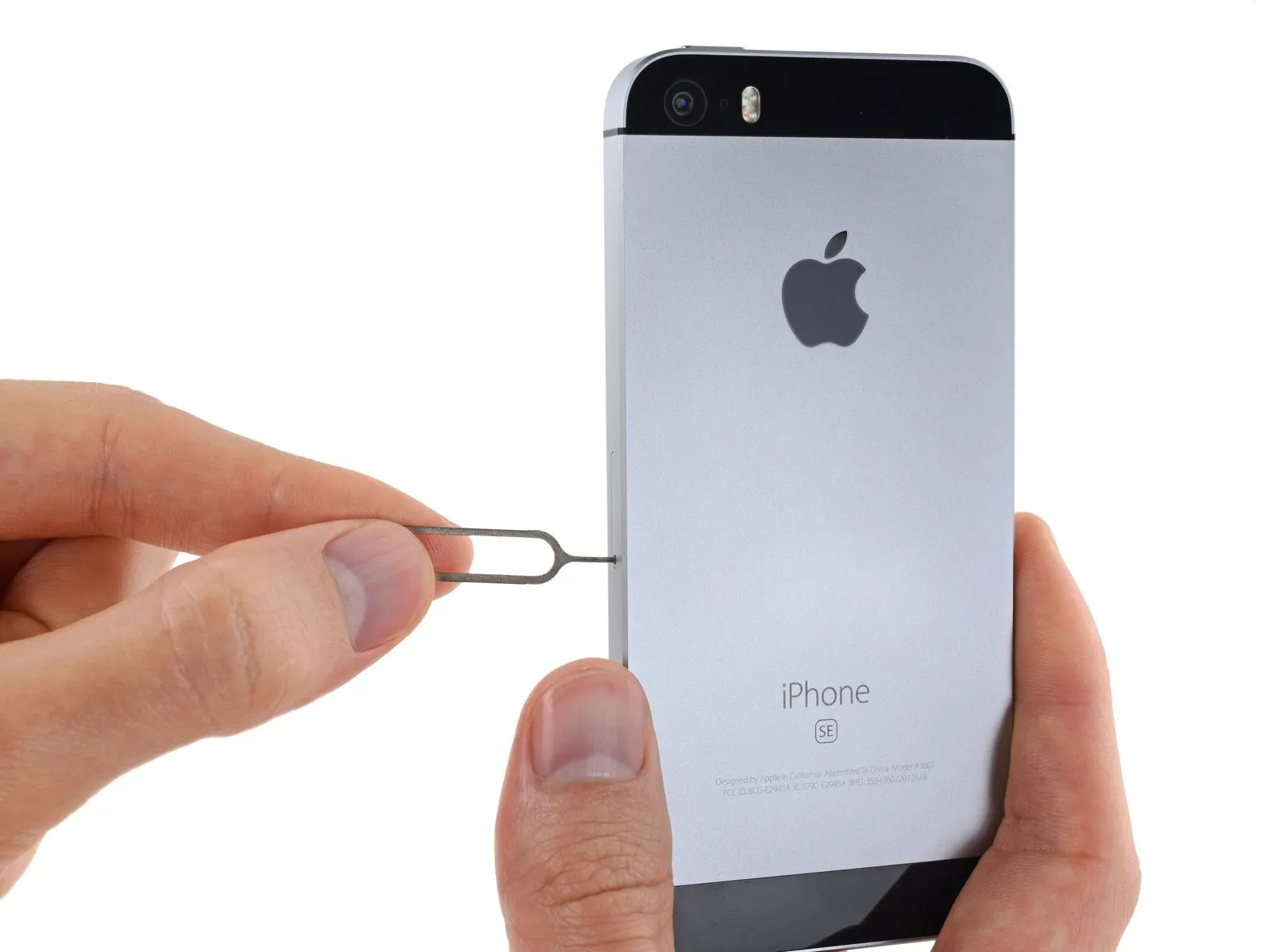
- Carefully position aUse the provided SIM card removal tool to release the SIM card tray.Use a paperclip, inserted into the small aperture on the SIM card tray, to release it.
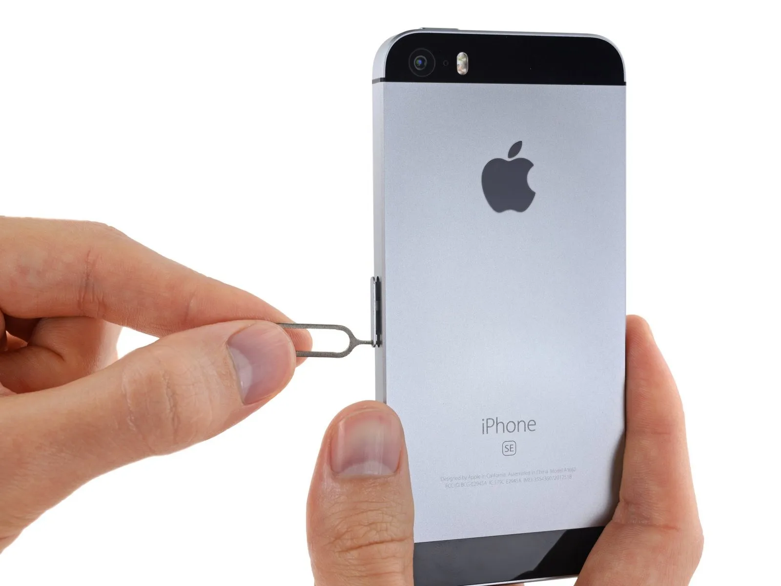
- Apply substantial pressure to release the tray.
Step 24
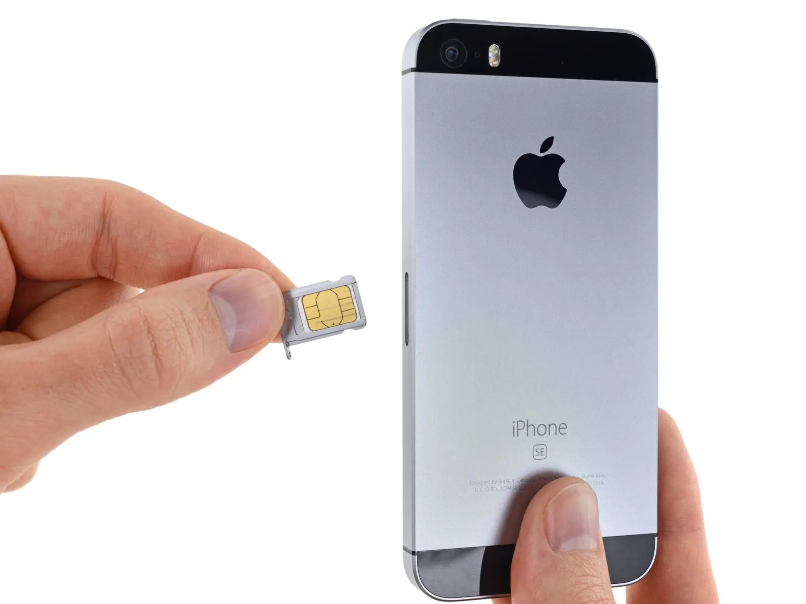
- Carefully detach the component, ensuring no damage occurs.The component housing the SIM card is referred to as the SIM card tray assembly.Retrieve the component from the iPhone.
- Confirm the SIM card's alignment with the tray before sliding it back in.
Step 25 | SIM Eject Lever
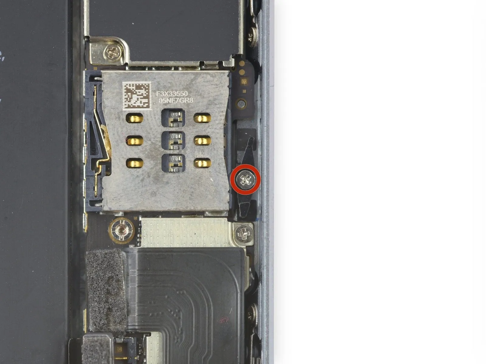
- Carefully detach theUse a Phillips head screwdriver, size #00, with a tip measuring 2.1 millimeters.Ensure the SIM eject lever is firmly in place.
Step 26
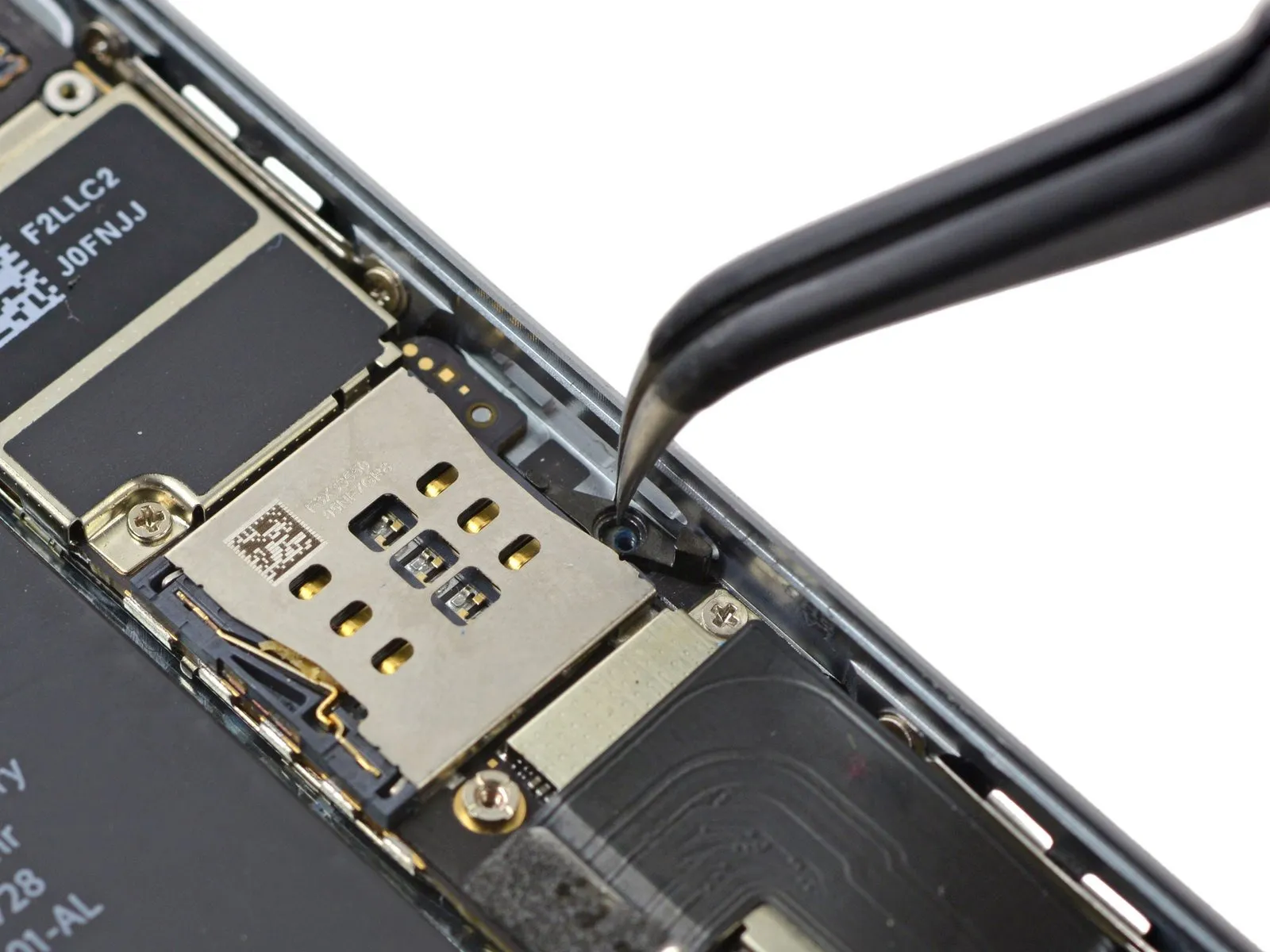
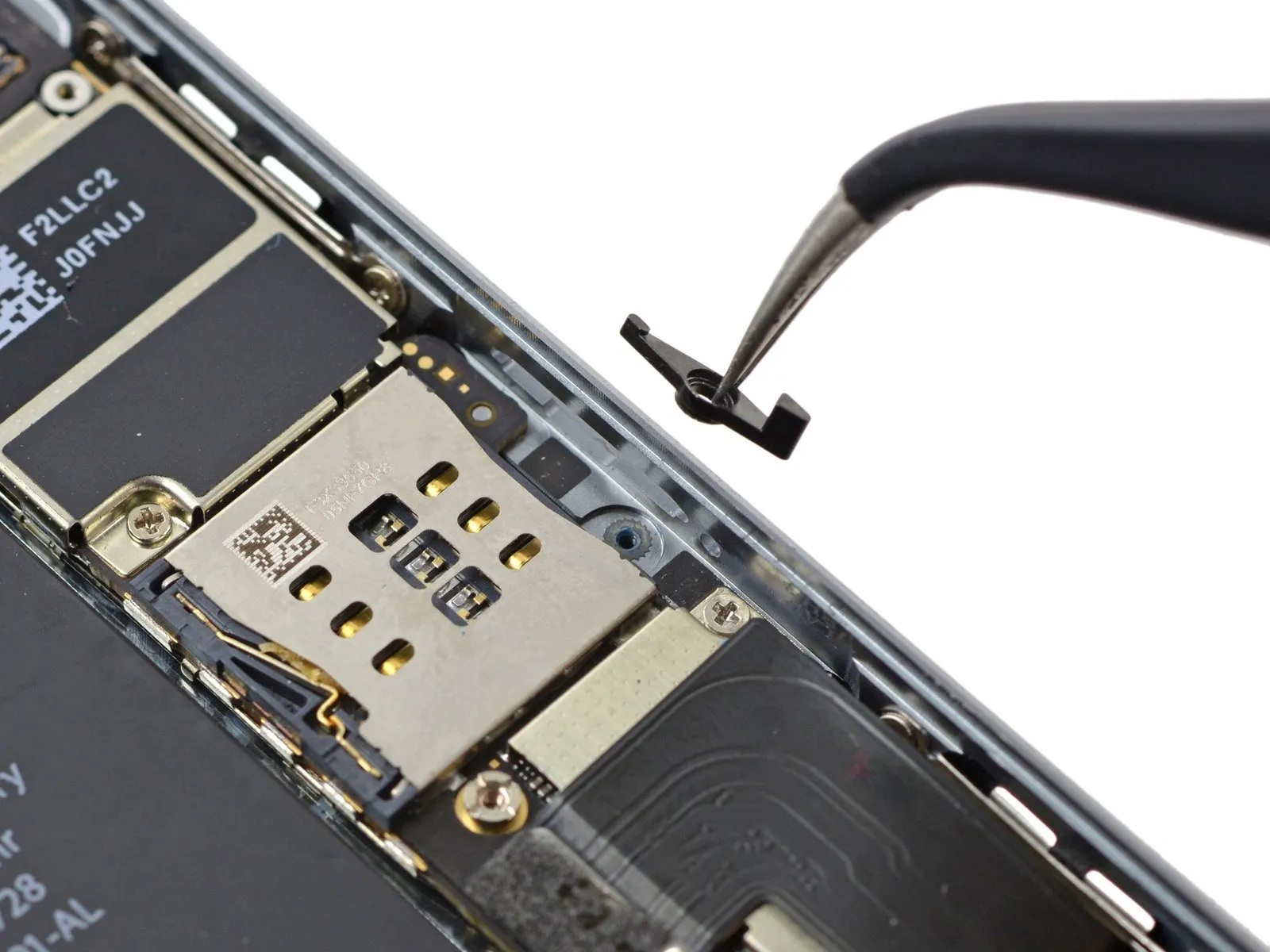
- Using a compatible tool, carefully extract the SIM eject lever from the iPhone.
- Ensure correct placement during reassembly by aligning the component's broader extremity with the SIM card release aperture.