iPhone SE 2020 Lightning Connector Assembly Replacement
Should attempts to clean the Lightning port prove ineffective, proceed with this procedure to substitute the Lightning connector assembly.The Lightning connector assembly, which is the focus of this replacement, incorporates the lower microphones, antenna converter cable, and the Lightning connector itself.Substitution of this component necessitates careful attention to detail due to the integrated nature of its sub-elements.Successful completion of this repair requires familiarity with micro-soldering techniques and the use of specialized tools.Prior to commencing work, ensure a full understanding of the potential risks and necessary precautions associated with device disassembly and component replacement.
Step 1 | Remove the SIM card tray


- Utilize a SIM card eject tool, a small bit, or a straightened paperclip, carefully inserting it into the aperture located on the SIM card tray.
- Apply pressure to the tray to initiate its ejection.
- Ejection might necessitate a considerable amount of force to overcome resistance.
Step 2

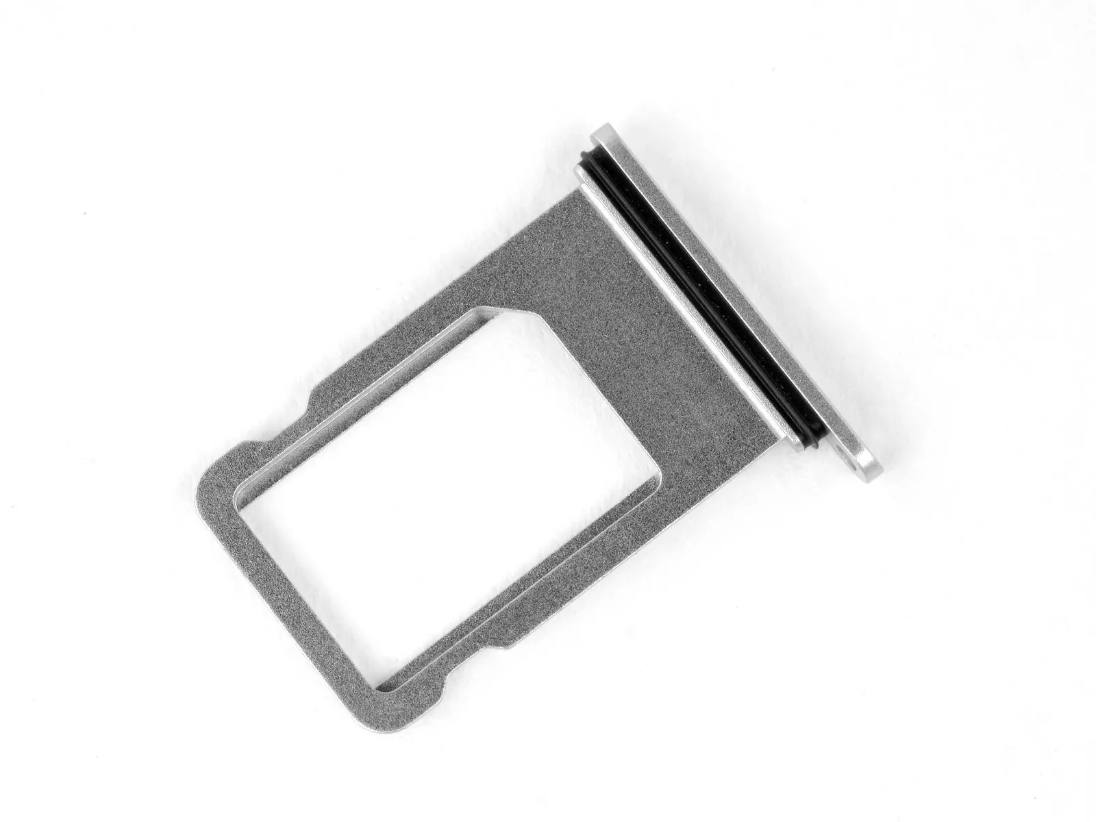
- Extract the SIM card tray from the iPhone enclosure.
- The SIM card should readily disengage from its holding feature within the tray.
- During reinsertion of the SIM card, confirm its correct alignment with the tray's design.
- A delicate rubber seal encircling the SIM card tray offers resistance to water and particulate matter; a compromised or absent seal necessitates gasket replacement or SIM card tray substitution to safeguard the iPhone’s internal circuitry.
Step 3 | Remove the pentalobe screws
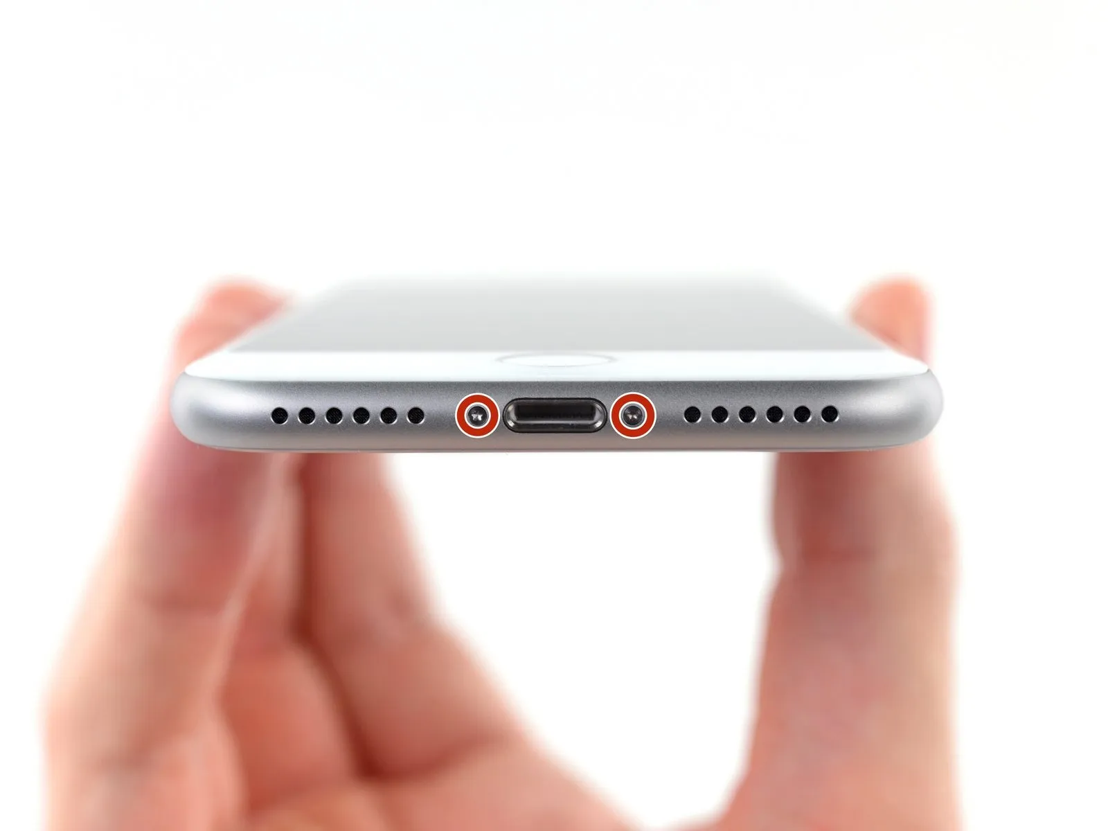
- To mitigate fire or explosion hazards, ensure the iPhone's lithium-ion battery is depleted to less than 25% charge prior to commencing any work; a fully charged battery poses a significant risk if damaged.
- Deactivate the iPhone's power supply to prevent electrical hazards and facilitate safe disassembly.
- Using a 3.5 mm pentalobe screwdriver, extract the pair of screws securing the lower edge of the iPhone’s casing.
- Disassembly that separates the display from the body of the iPhone will irreversibly damage the device’s water resistance; either obtain replacement sealing components beforehand or exercise extreme caution to prevent moisture ingress during reassembly if new seals are not used.
Step 4 | Mark your opening picks


- Excessive insertion of a prying tool risks harm to the device's internal components; therefore, implement a marking procedure to safeguard against such damage.
- Utilize a permanent marker to create a visible indication on the prying tool, precisely 3 millimeters from its distal end.
- For enhanced precision, consider marking the remaining corners of the tool with varied distances from the tip.
- As an alternative method, affix a coin to the prying tool's tip using adhesive tape, ensuring the coin's edge is positioned 3 millimeters from the tool's point.
Step 5 | Anti-Clamp instructions


- To disengage the Anti-Clamp's securing mechanism, retract the blue handle towards the rear.
- Carefully maneuver the arms of the device across either the left or right lateral side of the iPhone.
- Place the suction cups in proximity to the lower edge of the iPhone, positioning one on the front face and one on the rear, directly above the home button.
- Apply pressure by compressing the cups together, thereby establishing a secure vacuum seal on the intended surface.
- Should the iPhone's exterior exhibit excessive slipperiness, hindering the Anti-Clamp's ability to maintain adhesion, applying adhesive tape can enhance surface friction.
Step 6


- Advance the blue handle to engage the locking mechanism on the arms.
- Rotate the handle a full 360-degree circle, or continue until the cups exhibit signs of deformation.
- Maintain precise alignment between the suction cups; should misalignment occur, slightly release the suction cups and readjust the arms.
Step 7


- Employing an iOpener that has been heated, carefully guide it between the Anti-Clamp’s arms; alternative heat sources like hair dryers, heat guns, or hot plates are permissible, however, exercise caution to avoid display or battery damage due to excessive temperatures.
- Position the iOpener in a folded configuration, ensuring it rests along the iPhone’s lower edge.
- Allow a sixty-second interval to permit the adhesive to loosen and establish a separation.
- Introduce an opening pick into the newly formed space.
- Should the Anti-Clamp fail to generate an adequate separation, increase heat application to the targeted region and incrementally rotate the handle by ninety degrees; avoid rotations exceeding ninety degrees, and incorporate a sixty-second waiting period between adjustments, allowing the device and time to facilitate separation.
Proceed past the subsequent three procedural steps.
Step 8 | Heat the display
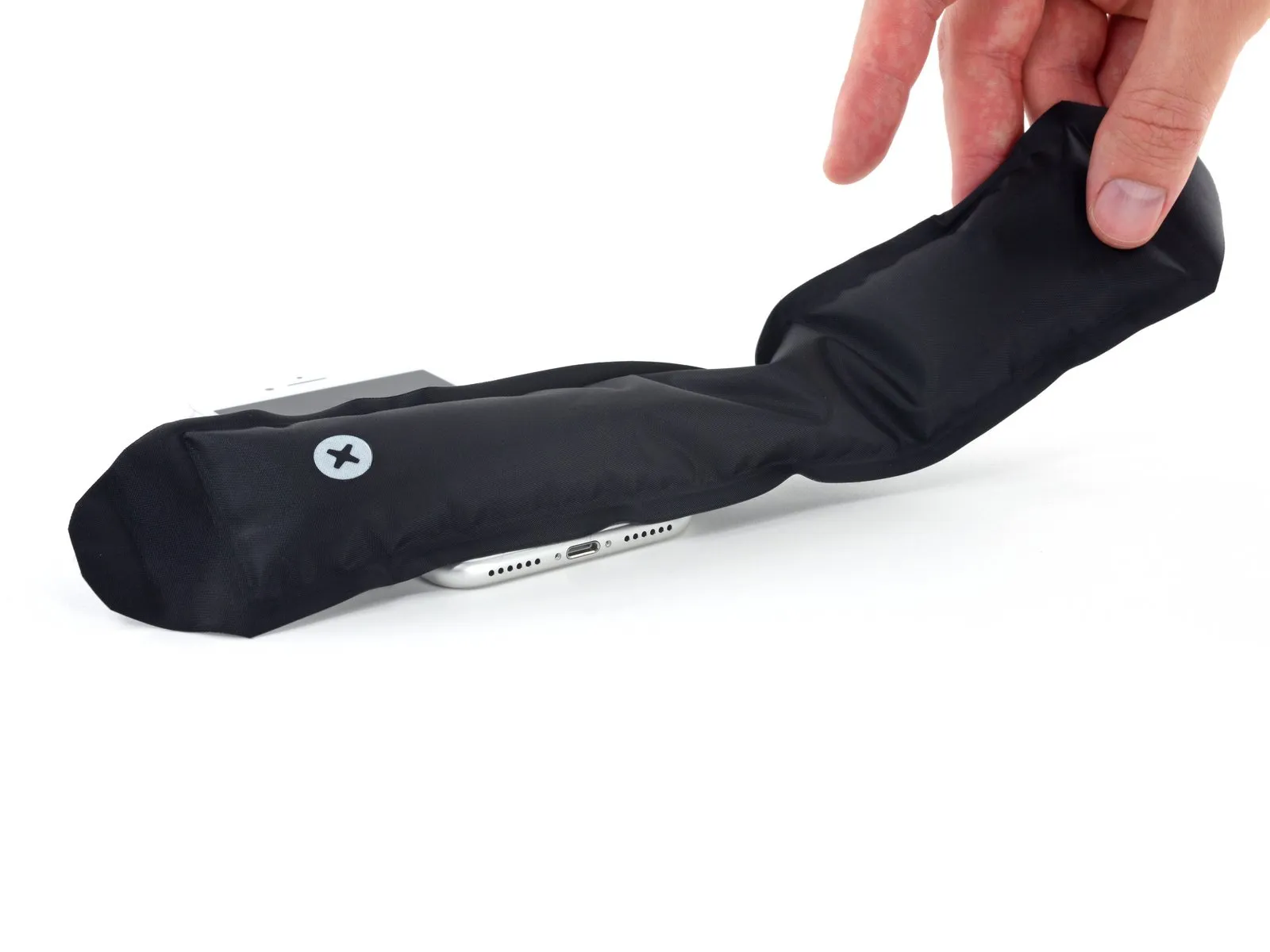
Instructions for detaching the display assembly involve utilizing a suction cup, as detailed in the following procedures.
Applying heat to the phone's bottom border facilitates the loosening of the adhesive bonds holding the screen in place, thereby simplifying separation.
To reduce adhesive strength, employ a hairdryer or an iOpener, directing it towards the lower edge of the device for approximately 90 seconds.
Step 9 | Separate the display
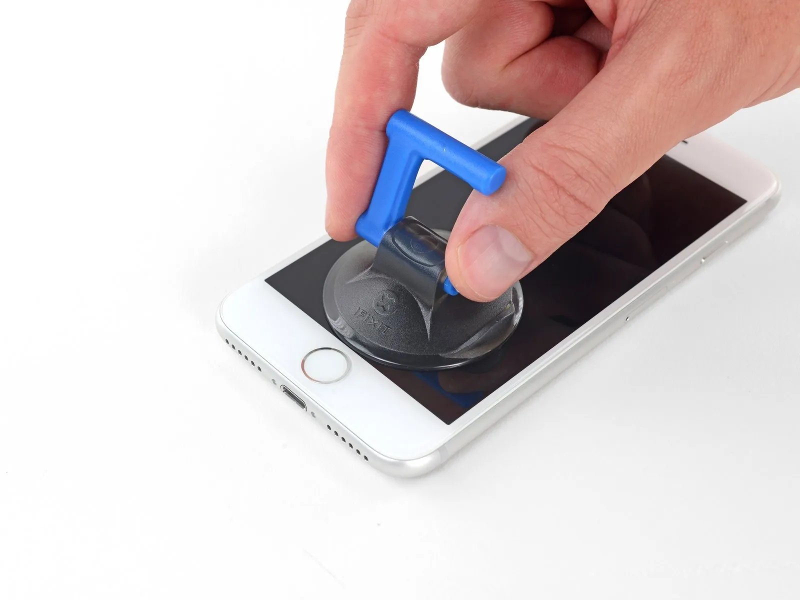

Securely affix a suction cup to the lower portion of the front panel, positioning it directly over the home button's area.
- Ensure the suction cup's surface area remains clear of the home button to guarantee a complete and airtight bond between the cup and the glass.
Step 10
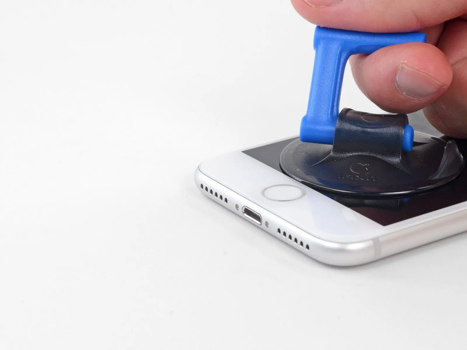


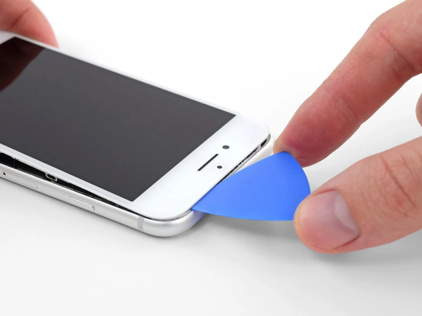
- Apply steady, forceful upward pressure to the suction cup to establish a small separation between the display assembly and the device's surrounding structure.
- Due to the robust, waterproof sealant securing the display, a considerable amount of force may be necessary to initially create this separation; if difficulty arises, additional heat application combined with gentle, oscillating screen movement can help to reduce the adhesive's strength, facilitating the creation of a sufficient gap for tool insertion.
Step 11
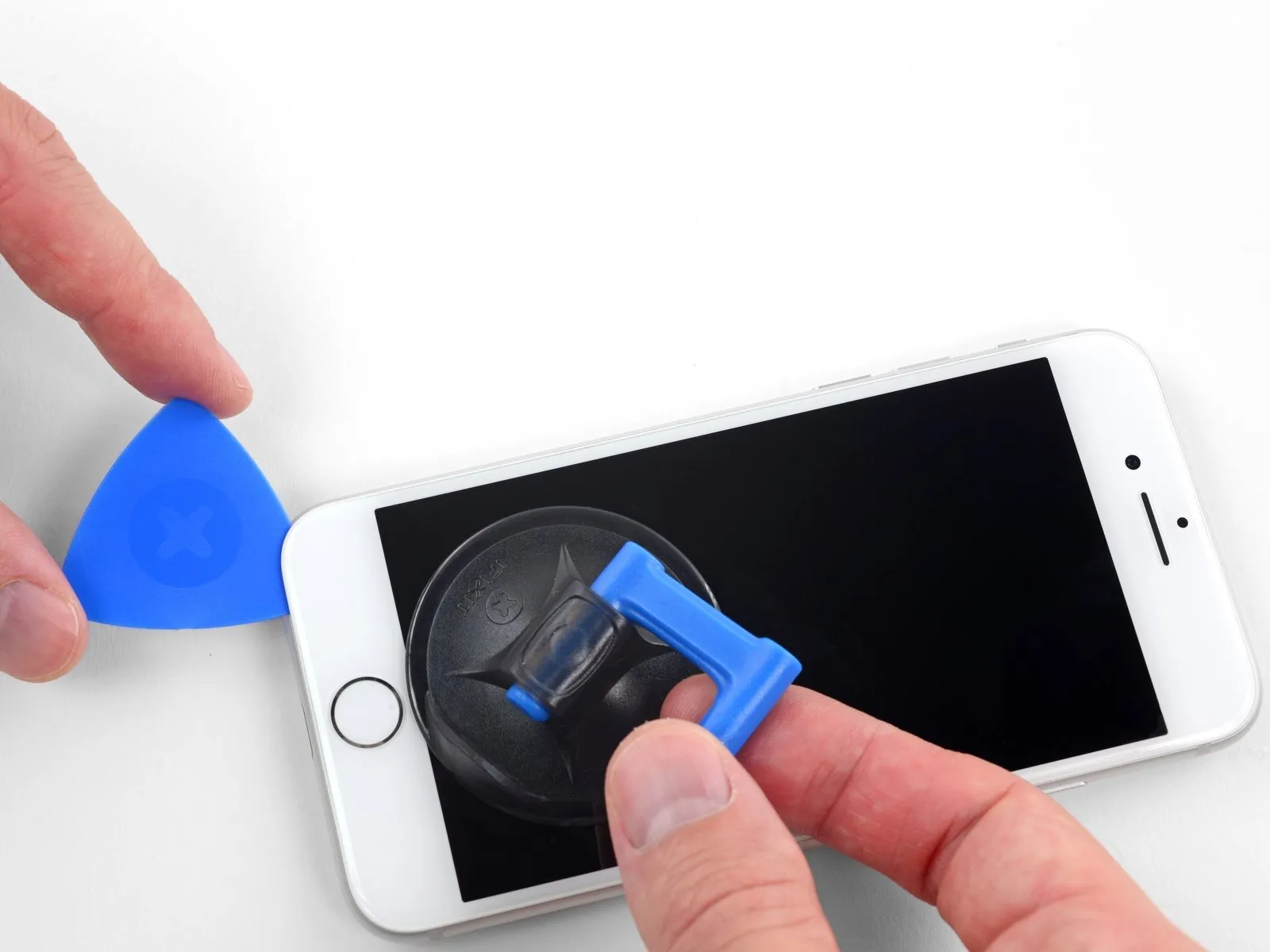


- Avoid attempting to dislodge the display's upper edge from the rear casing, as it is secured by fragile plastic clips susceptible to breakage.
Step 12 | Screen information

Step 13
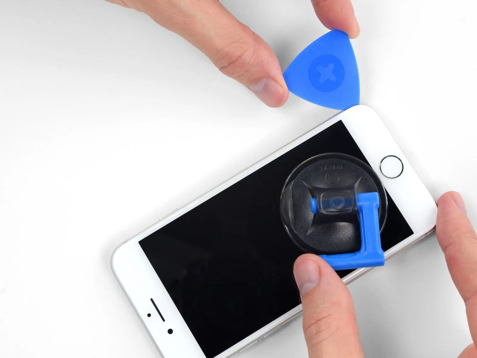


- To prevent potential harm to the delicate display cable connections, ensure the tool's insertion depth remains no greater than 3 millimeters.
Step 14


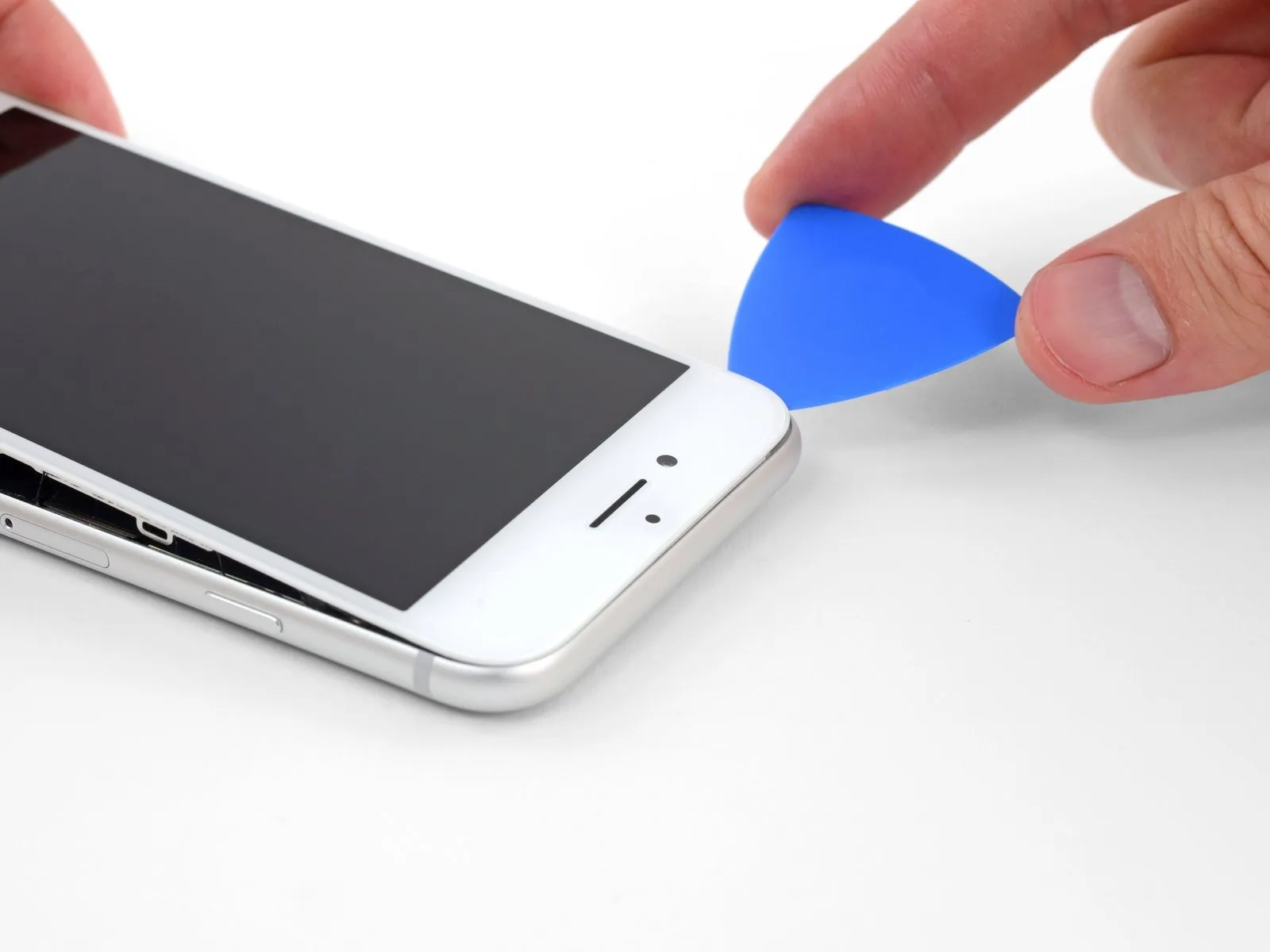
- Restrict the display's elevation to a maximum angle of 15 degrees to prevent potential damage or separation of the flexible ribbon cables.
Step 15

Step 16


Step 17


Initiate the iPhone's disassembly process by pivoting the display assembly upwards, commencing from the left edge, mimicking the action of opening a book's cover.
Refrain from completely detaching the display at this stage, because multiple delicate ribbon cables maintain its electrical connection to the device's logic board.
Secure the display in an upright position using a support to prevent it from obstructing access to the internal components during the repair.
Step 18 | Disconnect the battery


To detach the lower display cable bracket from the logic board, begin by eliminating the four Phillips screws that hold it in place, noting their specific dimensions.
- Specifically, two screws measure 1.3 millimeters in length.Additionally, two screws have a length of 2.8 millimeters.During the entire repair process, meticulously organize and track all removed screws to ensure correct placement during reassembly.
- Incorrect screw placement can result in irreversible damage to the device's components.Proceed with the removal of the bracket after addressing the screw fastenings.The bracket's removal is the subsequent step in the repair procedure.
Maintaining a record of screw locations is crucial for successful reassembly.
Careful attention to screw size and placement is essential to prevent component damage.
Step 19


Employing a spudger's tip, disengage the battery connector from its corresponding receptacle on the logic board.
To inhibit unintended power delivery to the device throughout the repair process, gently deflect the battery connector cable away from the logic board's socket.
Step 20 | Disconnect the display and digitizer


Employing the tip of a spudger, carefully disengage the lower display connector from its receptacle.
For reattachment, apply pressure to one edge of the connector until a secure click is heard, then repeat the process on the opposing edge, avoiding any pressure on the central portion; even minor misalignment risks bending the connector and causing irreversible harm.
Step 21


Step 22


- To detach the bracket that covers the front panel sensor assembly connector, begin by eliminating the three fasteners.Utilize a Phillips screwdriver with a bit size of 1.3 millimeters to loosen and remove the screws.The screws are specifically designed to hold the bracket in place, protecting the connector beneath.
- Following screw removal, the bracket can now be taken away from the device.
Step 23


Step 24 | Remove the display assembly
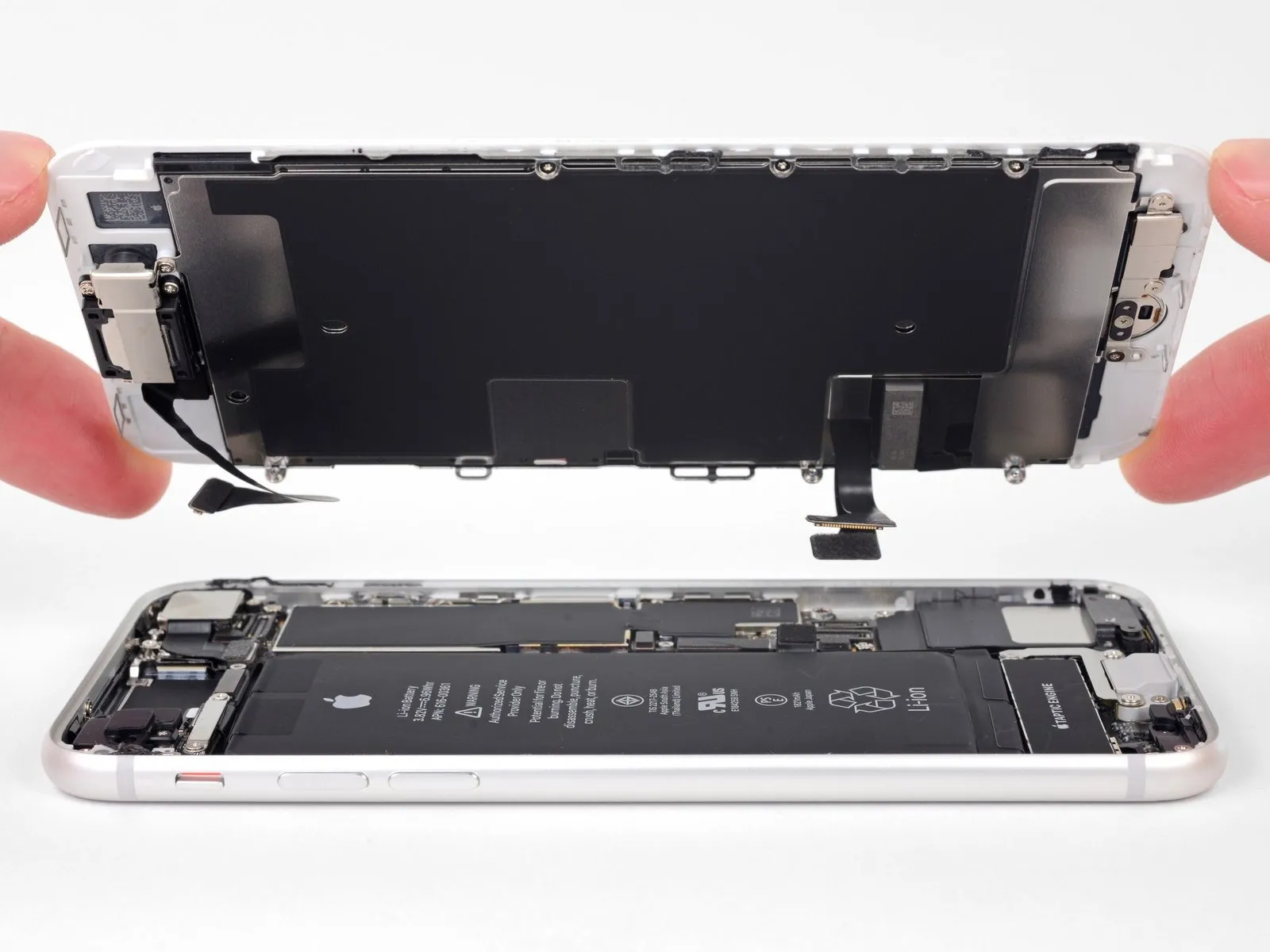
- Detach the display unit from the device.
- If edge adhesive replacement is desired during reassembly, halt the process at this stage.
Step 25 | Remove the Wi-Fi diversity antenna

- A single fastening element with a 1.3-millimeter diameter and a Y000 head profile is required.
- A Phillips head screw, measuring 2.7 millimeters in diameter, is necessary for this repair.
- A 2.9-millimeter Phillips head screw constitutes another essential component.
Step 26

Step 27
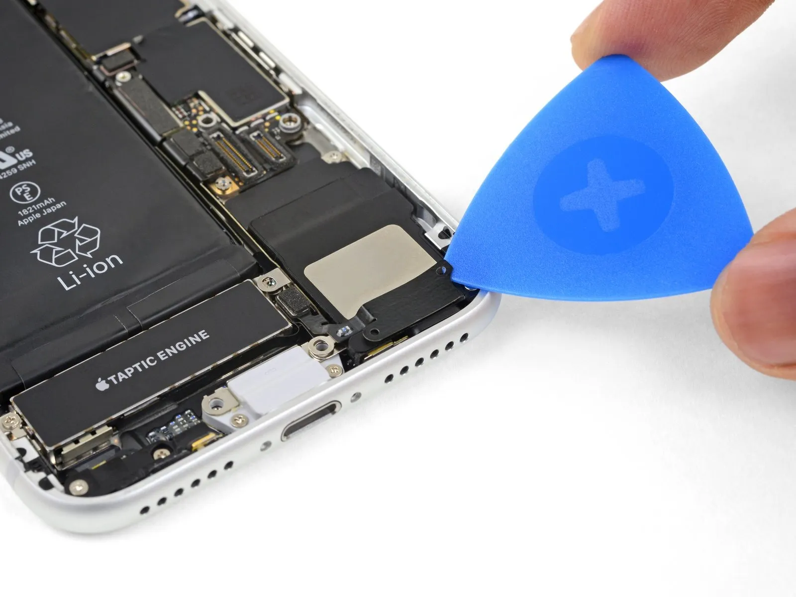


Carefully insert a separation tool between the antenna flex cable and the speaker's upper surface.
The flex cable is secured with a minimal adhesive bond; applying mild warmth using an iOpener or hairdryer can loosen the adhesive if separation proves difficult, facilitating a safer detachment.
Step 28


Employ the tip of a spudger tool to carefully lift and detach the diversity antenna flex cable connector from the logic board assembly.
Step 29


- To prevent the socket from moving, insert a thin opening pick beneath the antenna flex cable.
- Employ the tip of a spudger to lift and detach the antenna flex cable from its connector, maintaining socket stability with the opening pick.
- To simplify the reconnection process, utilize tweezers to position the flex cable's connector precisely within its socket, subsequently applying even pressure with the spudger's flat edge until a click confirms secure attachment.
Step 30

Step 31 | Remove the Taptic Engine

- To detach the Taptic Engine, begin by eliminating the two fasteners that hold it in place.
Specifically, a 2.1 mm Phillips head screw is present.Additionally, a 2.1 mm standoff screw is also securing the component.
For optimal removal of standoff screws, a specialized standoff screwdriver or bit is recommended.If a standoff screwdriver isn't available, a small flathead screwdriver can be utilized as an alternative. - However, when employing a flathead screwdriver, exercise heightened caution to prevent slippage and potential harm to adjacent parts.
Damage to nearby components could occur if the screwdriver slips during the removal process.
Step 32


- Employ the tip of a spudger to carefully lift the antenna cable socket, separating it from the adjacent connector.
Step 33


- Employ the tip of the spudger to carefully lift and detach the Taptic Engine flex cable.The spudger's pointed end facilitates separation of the connector from the Taptic Engine flex cable.To release the Taptic Engine flex cable, apply gentle prying force using the spudger's tip.Disconnecting the Taptic Engine flex cable requires precise manipulation with the spudger's point.Ensure the Taptic Engine flex cable is fully disengaged by utilizing the spudger's tip for leverage.
Step 34

Detach the Taptic Engine component.Exercise caution when disconnecting the Taptic Engine flex cable, as adhesive may secure it to the antenna flex cable.The Taptic Engine flex cable is susceptible to damage due to potential adhesion with the antenna flex cable.
Careful manipulation is required to prevent unintended damage to adjacent flex cables during removal.Adhesive securing the Taptic Engine flex cable to the antenna flex cable necessitates meticulous separation.To avoid accidental damage, proceed slowly and deliberately when detaching the Taptic Engine flex cable.
Step 35 | Remove the barometric vent

- Detach the barometric vent assembly from the rear case by unscrewing its fasteners.
A single 2-millimeter Phillips head screw is utilized for this purpose.Additionally, a 1.8-millimeter Phillips head screw is also present.
Employing the appropriate Phillips screwdriver is essential for successful removal.Carefully extract both screws to free the barometric vent.
Step 36


Step 37

Step 38 | Disconnect the logic board


Step 39

- To detach the camera bracket located at the rear of the device, first, loosen the two screws that hold it in place.
- A single 3.0-millimeter standoff screw is required for this process.
- Additionally, one 3.1-millimeter Phillips screw is also involved.
- Employing a standoff screwdriver or a compatible bit is the preferred method for removing standoff screws, minimizing the risk of damage.
- If a standoff screwdriver isn't available, a small flathead screwdriver can be used cautiously, being mindful of potential slippage and subsequent harm to nearby parts.
Step 40

Step 41


Step 42

- Detach the upper cable bracket by unscrewing the fasteners that hold it in place.
- A Phillips head screwdriver, sized 2.9 millimeters, is required for this step.
- A Phillips head screwdriver, sized 1.3 millimeters, is also necessary for disassembly.
Step 43

Step 44


Step 45 | Remove the top left antenna component

- To detach the upper-left antenna assembly, begin by eliminating the three fasteners.Utilize a Phillips head screwdriver, specifically one with a 1.3 mm tip, for this process. These screws hold the antenna component in place on the left side of the device's top surface.Carefully unscrew and retain these components for reassembly.
Step 46

- Detach the antenna assembly from the case's upper edge by eliminating the fastening provided by a Phillips screw with a 1.4 mm head.The screw, designed with a Phillips head and measuring 1.4 millimeters in width, serves to secure the antenna to the case's upper perimeter.To release the antenna, it is necessary to unscrew the 1.4 mm Phillips screw that holds it in place on the case's top edge.
Step 47

- Detach the antenna assembly.
Step 48 | Remove the top left grounding clip

- Detach the two screws that fasten the grounding clip, which is positioned on the logic board's upper left perimeter.A Phillips head screwdriver is required for this task.Specifically, a 1.5-millimeter Phillips screw must be removed.
- Additionally, a 2.6-millimeter Phillips screw needs to be unscrewed.These fasteners hold the grounding clip in place.
- Carefully unscrew the screws to release the clip.Ensure proper screw size selection to avoid damage to the logic board.
Step 49

Step 50 | Unscrew the logic board

- To detach the main circuit board, it is necessary to eliminate the three fasteners that hold it in place.
A Phillips-head screwdriver of 1.8 millimeters is required for one of the screws.
A standoff screw with a diameter of 2.5 millimeters is also needed.
Additionally, a standoff screw measuring 2.2 millimeters in diameter must be used.
Step 51


Step 52


Step 53 | Disconnect the Lightning connector assembly
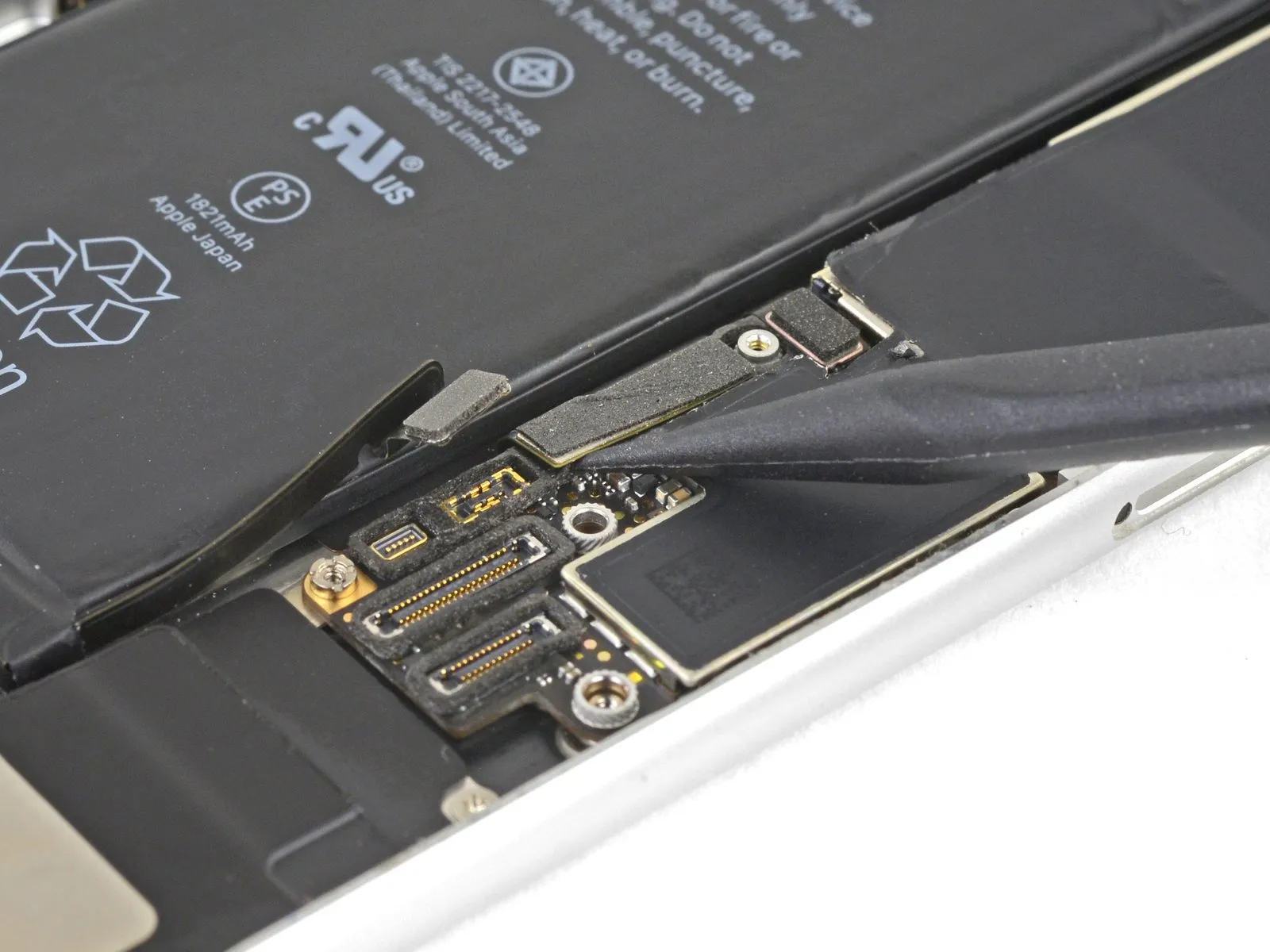

- Employ the tip of a spudger tool to carefully lift and detach the Lightning connector cable assembly from the main circuit board.The spudger's pointed end facilitates separation of the connector's securement without causing damage to surrounding components.Disconnection of the Lightning connector cable requires a prying action to overcome the adhesive or locking mechanism securing it to the logic board.
Step 54 | Disconnect the wireless charging coil


- Employ the tip of a spudger to carefully lift and detach the wireless charging coil's electrical connector.Applying gentle force with a spudger's pointed end facilitates separation of the wireless charging coil connector.To release the wireless charging coil connector, utilize a spudger, ensuring the tip is used for controlled prying action.
Step 55 | Remove the logic board


- Employ the planar edge of a spudger to carefully elevate the logic board's battery connector interface.Exercise caution to avoid exerting force on any connected wires.Should you encounter opposition during the lifting process, thoroughly inspect all cabling, connectors, and associated components for obstructions.
Ensure that no wires, connectors, or parts impede the board's movement to prevent damage.
Step 56


- To detach the logic board, carefully elevate it from its edges, positioning it close to the battery connector prior to separation.
Exercise caution to prevent the logic board from contacting or catching on any connected wires during the removal process.
Step 57 | Remove the speaker

- A fastener of 1.5 millimeters in diameter, utilizing a Phillips head, is required.Additionally, a fastener with a 2.1-millimeter diameter and a Phillips head is necessary.
- The speaker is affixed to the rear case using two screws, which must be removed to proceed.Employing a Phillips screwdriver, loosen and extract the two screws that provide the speaker's attachment to the rear housing.
Step 58

Step 59 | Remove the Lightning connector assembly

- A single screw, measuring 1.3 millimeters in diameter, requires a Phillips head screwdriver for removal.Two screws, each with a 2.2-millimeter diameter, also necessitate a Phillips head screwdriver for their extraction.
- Utilize a Phillips screwdriver to loosen and extract the fasteners that retain the Lightning connector cable's position.The fastening components consist of one 1.3 mm Phillips screw and two 2.2 mm Phillips screws, all of which must be removed.
Step 60

Step 61


- Employ the tip of a spudger to carefully detach the logic board's microphone from its adhesive mounting.The adhesive securing the microphone should be loosened, not the microphone itself, as illustrated.Gentle prying with the spudger is required to release the microphone from the adhesive.
- Partial separation of the adhesive, as depicted, is the intended outcome of this step.
Step 62


- Employ the tip of a spudger to carefully detach the battery-side microphone from its adhesive mount.The microphone's adhesive should be loosened, not fully detached, following the illustrated separation procedure.Gentle prying with the spudger is necessary to release the adhesive bond holding the microphone.
- Avoid complete removal of the microphone during this step; the goal is to break the adhesive seal as depicted.
Step 63

Utilize a heated iOpener, directing it against the device's lower surface at the indicated angle to facilitate separation of the flex cable adhesive.The application of heat with the iOpener assists in reducing the bond strength of the adhesive securing the flex cable.Proper angling of the iOpener during heating is crucial for effective adhesive softening and subsequent flex cable release.
Step 64


- Insert a separation tool beneath the upper section of the Lightning connector assembly's flexible cable, initiating the detachment of the cable from the device's rear casing.
- Carefully move the separation tool outwards, directing it away from the battery.
- A segment of the wireless charging coil is positioned directly beneath the Lightning connector flex cable.Excessive force during separation carries a risk of component damage.Applying undue pressure can potentially harm the coil.
- Should separation prove difficult, apply heat to the area behind the Lightning connector flex cable using a hair dryer or iOpener.Repeatedly applying heat will soften the adhesive, facilitating easier cable separation.The iOpener or hair dryer serves to re-liquefy the adhesive securing the flex cable.
Step 65


- Proceed with detaching the upper flex cable assembly, exercising caution to prevent harm to adjacent parts.
- Maintain the battery connector in a carefully folded position to preclude potential damage.
- Exercise extreme care to prevent any punctures to the battery, as compromise can result in the release of hazardous materials and/or combustion.
- Cease the pick's movement immediately upon reaching the battery's lower boundary.
Step 66


- Commence the separation process by inserting a prying tool at the phone's edge, directing its movement beneath the flex cable in the direction of the Lightning connector.
- Cease the tool's advancement once it has made contact with the Lightning connector.
Step 67


Carefully extract the Lightning connector from its opening located within the device's rear enclosure.The Lightning connector's removal necessitates a delicate manipulation to prevent damage to surrounding components.Ensure a firm but controlled grip when disengaging the connector to avoid unintended stress on the internal connections.
Step 68


- Insert a separating tool beneath the Lightning connector to create space between the components.The Lightning connector is the specific part to be targeted with the separation tool.Maintain the sliding motion of the tool to disengage the assembly.
- Keep sliding the tool until the Lightning connector assembly is completely detached from the rear case's lower surface.The Lightning connector assembly refers to the entire component including the connector and its attached wiring.Complete separation ensures the rear case can be removed without damaging the Lightning connector assembly.
Step 69


Step 70


- Detach the Lightning connector assembly from the device.
- Employ a non-conductive instrument to eliminate any remaining adhesive from the rear enclosure; utilizing a solvent with a high isopropyl alcohol concentration can aid in this cleaning process.
- Verify proper alignment of the Lightning connector assembly prior to peeling away the adhesive backing, ensuring the flex cable's aperture corresponds with the designated screw post to facilitate subsequent reconnection to the logic board.
Step 71


- Verify the presence of an antenna converter cable within your replacement part's components.Should the new part lack the antenna converter cable, carefully detach it from the original Lightning assembly using the tip of a spudger for transfer to the replacement.